
MSO4034B - Digital Oscilloscope TEKTRONIX - Free user manual and instructions
Find the device manual for free MSO4034B TEKTRONIX in PDF.
User questions about MSO4034B TEKTRONIX
0 question about this device. Answer the ones you know or ask your own.
Ask a new question about this device
Download the instructions for your Digital Oscilloscope in PDF format for free! Find your manual MSO4034B - TEKTRONIX and take your electronic device back in hand. On this page are published all the documents necessary for the use of your device. MSO4034B by TEKTRONIX.
USER MANUAL MSO4034B TEKTRONIX
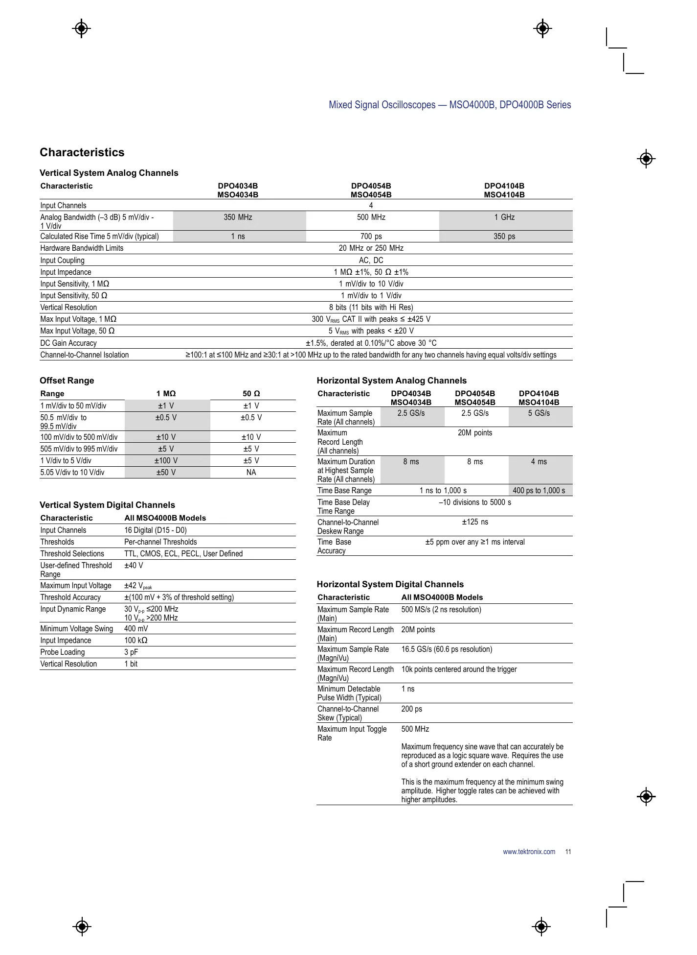
Vertical System Analog Channels
| Characteristic | DPO4034B MSO4034B | DPO4054B MSO4054B | DPO4104B MSO4104B |
| Input Channels | 4 | ||
| Analog Bandwidth (-3 dB) 5 mV/div - 1 V/div | 350 MHz | 500 MHz | 1 GHz |
| Calculated Rise Time 5 mV/div (typical) | 1 ns | 700 ps | 350 ps |
| Hardware Bandwidth Limits | 20 MHz or 250 MHz | ||
| Input Coupling | AC, DC | ||
| Input Impedance | 1 MΩ ±1%, 50 Ω ±1% | ||
| Input Sensitivity, 1 MΩ | 1 mV/div to 10 V/div | ||
| Input Sensitivity, 50 Ω | 1 mV/div to 1 V/div | ||
| Vertical Resolution | 8 bits (11 bits with Hi Res) | ||
| Max Input Voltage, 1 MΩ | 300 VRMS CAT II with peaks ≤ ±425 V | ||
| Max Input Voltage, 50 Ω | 5 VRMS with peaks < ±20 V | ||
| DC Gain Accuracy | ±1.5%, derated at 0.10%/°C above 30 °C | ||
| Channel-to-Channel Isolation | ≥100:1 at ≤100 MHz and ≥30:1 at >100 MHz up to the rated bandwidth for any two channels having equal volts/div settings | ||
Offset Range
| Range | 1 MΩ | 50 Ω |
| 1 mV/div to 50 mV/div | ±1 V | ±1 V |
| 50.5 mV/div to 99.5 mV/div | ±0.5 V | ±0.5 V |
| 100 mV/div to 500 mV/div | ±10 V | ±10 V |
| 505 mV/div to 995 mV/div | ±5 V | ±5 V |
| 1 V/div to 5 V/div | ±100 V | ±5 V |
| 5.05 V/div to 10 V/div | ±50 V | NA |
Vertical System Digital Channels
| Characteristic | All MSO4000B Models |
| Input Channels | 16 Digital (D15 - D0) |
| Thresholds | Per-channel Thresholds |
| Threshold Selections | TTL, CMOS, ECL, PECL, User Defined |
| User-defined Threshold Range | ±40 V |
| Maximum Input Voltage | ±42 Vpeak |
| Threshold Accuracy | ±(100 mV + 3% of threshold setting) |
| Input Dynamic Range | 30 Vp-p≤200 MHz 10 Vp-p>200 MHz |
| Minimum Voltage Swing | 400 mV |
| Input Impedance | 100 kΩ |
| Probe Loading | 3 pF |
| Vertical Resolution | 1 bit |
Horizontal System Analog Channels
| Characteristic | DPO4034B MSO4034B | DPO4054B MSO4054B | DPO4104B MSO4104B |
| Maximum Sample Rate (All channels) | 2.5 GS/s | 2.5 GS/s | 5 GS/s |
| Maximum Record Length (All channels) | 20M points | ||
| Maximum Duration at Highest Sample Rate (All channels) | 8 ms | 8 ms | 4 ms |
| Time Base Range | 1 ns to 1,000 s | 400 ps to 1,000 s | |
| Time Base Delay Time Range | -10 divisions to 5000 s | ||
| Channel-to-Channel Deskew Range | ±125 ns | ||
| Time Base Accuracy | ±5 ppm over any ≥1 ms interval | ||
Horizontal System Digital Channels
| Characteristic | All MSO4000B Models |
| Maximum Sample Rate (Main) | 500 MS/s (2 ns resolution) |
| Maximum Record Length (Main) | 20M points |
| Maximum Sample Rate (MagniVu) | 16.5 GS/s (60.6 ps resolution) |
| Maximum Record Length (MagniVu) | 10k points centered around the trigger |
| Minimum Detectable Pulse Width (Typical) | 1 ns |
| Channel-to-Channel Skew (Typical) | 200 ps |
| Maximum Input Toggle Rate | 500 MHz |
| Maximum frequency sine wave that can accurately be reproduced as a logic square wave. Requires the use of a short ground extender on each channel. | |
| This is the maximum frequency at the minimum swing amplitude. Higher toggle rates can be achieved with higher amplitudes. |
Trigger System
| Characteristic | Description |
| Main Trigger Modes | Auto, Normal, and Single |
| Trigger Coupling | DC, AC, HF reject (attenuates >50 kHz), LF reject (attenuates <50 kHz), noise reject (reduces sensitivity) |
| Trigger Holdoff Range | 20 ns to 8 s |
Trigger Sensitivity
| Characteristic | Description |
| Internal DC Coupled | |
| 1 MΩ Path (All models) | For 1 mV/div to 4.98 mV/div; 0.75 div from DC to 50 MHz, increasing to 1.3 div at rated bandwidth |
| 50 Ω Path (MSO/DPO4054B, MSO/DPO4034B) | For ≥5 mV/div; 0.4 div from DC to 50 MHz, increasing to 1 div at rated bandwidth |
| 50 Ω Path (MSO/DPO4104B) | 0.4 div from DC to 50 MHz, increasing to 1 div at rated bandwidth |
| External | |
| Auxiliary Input | 200 mV from DC to 50 MHz, increasing to 500 mV at rated bandwidth |
Trigger Level Range
| Characteristic | Description |
| Any Channel | ±8 divisions from center of screen |
| External (Auxiliary Input) | ±8 V |
Trigger Modes
| Mode | Description |
| Edge | Positive or negative slope on any channel or front-panel auxiliary input. Coupling includes DC, AC, HF reject, LF reject, and noise reject |
| Sequence (B-trigger) | Trigger Delay by Time - 4 ns to 8 s. Or Trigger Delay by Events - 1 to 4,000,000 events |
| Pulse Width | Trigger on width of positive or negative pulses that are >, <, =, or ≠ a specified period of time (4 ns to 8 s) |
| Timeout | Trigger when no pulse is detected within a specified time (4 ns to 8 s) |
| Runt | Trigger on a pulse that crosses one threshold but fails to cross a second threshold before crossing the first again |
| Logic | Trigger when any logical pattern of channels goes false or stays true for specified period of time (4 ns to 8 s). Any input can be used as a clock to look for the pattern on a clock edge. Pattern (AND, OR, NAND, NOR) specified for all analog and digital input channels defined as High, Low, or Don't Care |
| Setup and Hold | Trigger on violations of both setup time and hold time between clock and data present on any of the input channels |
| Rise/Fall Time | Trigger on pulse edge rates that are faster or slower than specified. Slope may be positive, negative, or either |
| Video | Trigger on all lines, odd, even, or all fields on NTSC, PAL, and SECAM video signals |
| Extended Video (Optional) | Trigger on 480p/60, 576p/50, 720p/30, 720p/50, 720p/60, 875i/60, 1080i/50, 1080i/60, 1080p/24, 1080p/24sF, 1080p/25, 1080p/30, 1080p/50, 1080p/60, and custom bi-level and tri-level sync video standards |
| I²C (Optional) | Trigger on Start, Repeated Start, Stop, Missing ACK, Address (7 or 10 bit), Data, or Address and Data on I²C buses up to 10 Mb/s |
| SPI (Optional) | Trigger on SS active, MOSI, MISO, or MOSI and MISO on SPI buses up to 50 Mb/s |
| USB (Optional) | Low-speed: Trigger on Sync, Reset, Suspend, Resume, End of Packet, Token (Address) Packet, Data Packet, Handshake Packet, Special Packet, Error.Token packet trigger – Any token type, SOF, OUT, IN, SETUP; Address can be specified for Any Token, OUT, IN, and SETUP token types. Address can be further specified to trigger on ≤, <, =, >, ≥, ≠ a particular value, or inside or outside of a range. Frame number can be specified for SOFToken using binary, hex, unsigned decimal and don't care digits.Data packet trigger – Any data type, DATA0, DATA1; Data can be further specified to trigger on ≤, <, =, >, ≥, ≠ a particular data value, or inside or outside of a range.Handshake packet trigger – Any handshake type, ACK, NAK, STALL.Special packet trigger – Any special type, Reserved.Error trigger – PID Check, CRC5 or CRC16, Bit Stuffing. |
| Full-speed: Trigger on Sync, Reset, Suspend, Resume, End of Packet, Token (Address) Packet, Data Packet, Handshake Packet, Special Packet, Error.Token packet trigger – Any token type, SOF, OUT, IN, SETUP; Address can be specified for Any Token, OUT, IN, and SETUP token types. Address can be further specified to trigger on ≤, <, =, >, ≥, ≠ a particular value, or inside or outside of a range.Framme number can be specified for SOFToken using binary, hex, unsigned decimal and don't care digits.Data packet trigger – Any data type, DATA0, DATA1; Data can be further specified to trigger on ≤, <, =, >, ≥, ≠ a particular data value, or inside or outside of a range.Handshake packet trigger – Any handshake type, ACK, NAK, STALL.Special packet trigger – Any special type, PRE, Reserved.Error trigger – PID Check, CRC5 or CRC16, Bit Stuffing. | |
| High-speed: Trigger on Sync, Reset, Suspend, Resume, End of Packet, Token (Address) Packet, Data Packet, Handshake Packet, Special Packet, Error.Token packet trigger – Any token type, SOF, OUT, IN, SETUP; Address can be specified for Any Token, OUT, IN, and SETUP token types. Address can be further specified to trigger on ≤, <, =, >, ≥, ≠ a particular value, or inside or outside of a range.SOF token using binary, hex, unsigned decimal and don't care digits.Data packet trigger – Any data type, DATA0, DATA1, DATA2, DATAM; Data can be further specified to trigger on ≤, <, =, >, ≥, ≠ a particular data value, or inside or outside of a range.Handshake packet trigger – Any handshake type, ACK, NAK, STALL, NYET.Special packet trigger – Any special type, ERR, SPLIT, PING; Reserved. SPLIT packet components that can be specified include:Hub AddressStart/Complete – Don't Care, Start (SSPLIT), Complete (CSPLIT)Port AddressStart and End bits – Don't Care, Control/Bulk/Interrupt (Full-speed Device, Low-speed Device), Isochronous (Data is Middle, Data is End, Data is Start, Data is All)Endpoint Type – Don't Care, Control, Isochronous, Bulk, InterruptError trigger – PID Check, CRC5 or CRC16, Any. | |
| High-speed support only available on MSO4104B and DPO4104B models. | |
| Ethernet (Optional) | 10BASE-T: Trigger on Start Frame Delimiter, MAC Addresses, MAC Q-Tag Control Information, MAC Length/Type, IP Header, TCP Header,TCP/IPv4/MAC Client Data, End of Packet, FCS (CRC) Error.MAC Addresses – Trigger on Source and Destination 48-bit address values.MAC Q-Tag Control Information – Trigger on Q-Tag 32-bit value.MAC Length/Type – Trigger on ≤, <, =, >, ≥, ≠ a particular 16-bit value, or inside or outside of a range.IP Header – Trigger on IP Protocol 8-bit value, Source Address, Destination Address.TCP Header – Trigger on Source Port, Destination Port, Sequence Number, and Ack Number.TCP/IPv4/MAC Client Data – Trigger on ≤, <, =, >, ≥, ≠ a particular data value, or inside or outside of a range. Selectable number of bytes to trigger on from 1-16. Byte offset options of Don't Care, 0-1499. |
| 100BASE-TX: Trigger on Start Frame Delimiter, MAC Addresses, MAC Q-Tag Control Information, MAC Length/Type, IP Header, TCP Header,TCP/IPv4/MAC Client Data, End of Packet, Idle, FCS (CRC) Error.MAC Addresses – Trigger on Source and Destination 48-bit address values.MAC Q-Tag Control Information – Trigger on Q-Tag 32-bit value.MAC Length/Type – Trigger on ≤, <, =, >, ≥, ≠ a particular 16-bit value, or inside or outside of a range.IP Header – Trigger on IP Protocol 8-bit value, Source Address, Destination Address.TCP Header – Trigger on Source Port. Destination Port, Sequence Number, and Ack Number.TCP/IPv4/MAC Client Data – Trigger on ≤, <, =, >, ≥, ≠ a particular data value, or inside or outside of a range. Selectable number of bytes to trigger on from 1-16. Byte offset options of Don't Care, 0-1499. | |
| CAN (Optional) | Trigger on Start of Frame, Frame Type (data, remote, error, overload), Identifier (standard or extended), Data, Identifier and Data, End of Frame, Missing ACK, or Bit Stuffing Error on CAN signals up to 1 Mb/s. Data can be further specified to trigger on ≤, <, =, >, ≥, or ≠ a specific data value.User-adjustable sample point is set to 50% by default |
| LIN (Optional) | Trigger on Sync, Identifier, Data, Identifier and Data, Wakeup Frame, Sleep Frame, Errors such as Sync, Parity, or Checksum Errors up to 100 Kb/s (by LIN definition, 20 Kb/s) |
| FlexRay (Optional) | Trigger on Start of Frame, Type of Frame (Normal, Payload, Null, Sync, Startup), Identifier, Cycle Count, Complete Header Field, Data, Identifier and Data, End of Frame or Errors such as Header CRC, Trailer CRC, Null Frame, Sync Frame, or Startup Frame Errors up to 100 Mb/s |
| RS-232/422/485/UART (Optional) | Trigger on Tx Start Bit, Rx Start Bit, Tx End of Packet, Rx End of Packet, Tx Data, Rx Data, Tx Parity Error, and Rx Parity Error up to 10 Mb/s |
| MIL-STD-1553 (Optional) | Trigger on Sync, Word Type, Parity Error. Data can be further specified to trigger on ≤, <, =, >, ≥, ≠ a specific data value, or inside or outside of a range. |
| I2S/LJ/RJ/TDM (Optional) | Trigger on Word Select, Frame Sync, or Data. Data can be further specified to trigger on ≤, <, =, >, ≥, ≠ a specific data value, or inside or outside of a rangeMaximum data rate for I2S/LJ/RJ is 12.5 Mb/sMaximum data rate for TDM is 25 Mb/s |
| Parallel (Available on MSO models only) | Trigger on a parallel bus data value. Parallel bus can be from 1 to 20 bits in size. Binary and Hex radices are supported |
Acquisition Modes
| Mode | Description |
| Sample | Acquire sampled values |
| Peak Detect | Captures glitches as narrow as 800 ps (1 GHz models) or 1.6 ns (500 MHz and 350 MHz models) at all sweep speeds |
| Averaging | From 2 to 512 waveforms included in average |
| Envelope | Min-Max envelope reflecting Peak Detect data over multiple acquisitions |
| Hi Res | Real-time boxcar averaging reduces random noise and increases vertical resolution |
| Roll | Scrolls waveforms right to left across the screen at sweep speeds slower than or equal to 40 ms/div |
Waveform Measurements
| Measurement | Description |
| Cursors | Waveform and Screen |
| Automatic Measurements | 29, of which up to four can be displayed on-screen at any one time. Measurements include: Period, Frequency, Delay, Rise Time, Fall Time, Positive Duty Cycle, Negative Duty Cycle, Positive Pulse Width, Negative Pulse Width, Burst Width, Phase, Positive Overshoot, Negative Overshoot, Peak-to-Peak, Amplitude, High, Low, Max, Min, Mean, Cycle Mean, RMS, Cycle RMS, Positive Pulse Count, Negative Pulse Count, Rising Edge Count, Falling Edge Count, Area and Cycle Area |
| Measurement Statistics | Mean, Min, Max, Standard Deviation |
| Reference Levels | User-definable reference levels for automatic measurements can be specified in either percent or units |
| Gating | Isolate the specific occurrence within an acquisition to take measurements on, using either the screen or waveform cursors |
| Waveform Histogram | A waveform histogram provides an array of data values representing the total number of hits inside of a user-defined region of the display. A waveform histogram is both a visual graph of the hit distribution as well as a numeric array of values that can be measured. Sources – Channel 1, Channel 2, Channel 3, Channel 4, Ref 1, Ref 2, Ref 3, Ref 4, Math Types – Vertical, Horizontal |
| Waveform Histogram Measurements | Waveform Count, Hits in Box, Peak Hits, Median, Max, Min, Peak-to-Peak, Mean, Standard Deviation, Sigma 1, Sigma 2, Sigma 3 |
Waveform Math
| Characteristic | Description |
| Arithmetic | Add, subtract, multiply, and divide waveforms |
| Math Functions | Integrate, Differentiate, FFT |
| FFT | Spectral magnitude |
| FFT Vertical Scale: Linear RMS or dBV RMS | |
| FFT Window Settings: Rectangular, Hamming, Hanning, Blackman Harris | |
| Advanced Math | Define extensive algebraic expressions including waveforms, reference waveforms, math functions. Perform math on math using complex equations (FFT, Intg, Diff, Log, Exp, Squ, Abs, Sine, Cosine, Tangent, Rad, Deg), scalars, up to two user-adjustable variables and results of parametric measurements (Period, Freq, Delay, Rise, Fall, PosWidth, NegWidth, BurstWidth, Phase, PosDutyCycle, NegDutyCycle, PosOverShoot, NegOverShoot, PeakPeak, Amplitude, RMS, CycleRMS, High, Low, Max, Min, Mean, CycleMean, Area, CycleArea, and trend plots) e.g. (Intg(Ch1-Mean(Ch1))×1.414×VAR1) |
Power Measurements (Optional)
| Measurement | Description |
| Power Quality Measurements | VRMS, VCrest Factor, Frequency, IRMS, Icrest Factor, True Power, Apparent Power, Reactive Power, Power Factor, Phase Angle |
| Switching Loss Measurements | Power Loss: Ton, Toff, Conduction, Total |
| Energy Loss: Ton, Toff, Conduction, Total | |
| Harmonics | THD-F, THD-R, RMS measurements |
| Graphical and table displays of harmonics | |
| Test to IEC61000-3-2 Class A and MIL-STD-1399 | |
| Ripple Measurements | Vripple and Iripple |
| Modulation Analysis | Graphical display of +Pulse Width, -Pulse Width, Period, Frequency, +Duty Cycle, and -Duty Cycle modulation types |
| Safe Operating Area | Graphical display and mask testing of switching device safe operating area measurements |
| dV/dt and dl/dt Measurements | Cursor measurements of slew rate |
Limit/Mask Testing (Optional)
| Characteristic | Description |
| Included Standard Masks | ITU-T, ANSI T1.102, USB |
| Test Source | Limit Test: Any Ch1 - Ch4 or any R1 - R4 Mask Test: Any Ch1 - Ch4 |
| Mask Creation | Limit test vertical tolerance from 0 to 1 division in 1 m division increments; Limit test horizontal tolerance from 0 to 500 m division in 1 m division increments |
| Load standard mask from internal memory | |
| Load custom mask from text file with up to 8 segments | |
| Mask Scaling | Lock to Source ON (mask automatically re-scales with source-channel settings changes) Lock to Source OFF (mask does not re-scale with source-channel settings changes) |
| Test Criteria Run Until | Minimum number of waveforms (from 1 to 1,000,000; Infinity) Minimum elapsed time (from 1 second to 48 hours; Infinity) |
| Violation Threshold | From 1 to 1,000,000 |
| Actions on Test Failure | Stop acquisition, save screen image to file, save waveform to file, print screen image, trigger out pulse, set remote interface SRQ |
| Actions on Test Complete | Trigger out pulse, set remote interface SRQ |
| Results Display | Test status, total waveforms, number of violations, violation rate, total tests, failed tests, test failure rate, elapsed time, total hits for each mask segment |
Software
| Software | Description |
| NI LabVIEW | A fully interactive measurement software environment optimized for the MSO/DPO4000B Series, enables you to instantly acquire, generate, analyze, compare, import, and save measurement data and signals using an intuitive drag-and-drop user interface that does not require any programming. |
| SignalExpress Tektronix Edition | Standard MSO/DPO4000B Series support for acquiring, controlling, viewing, and exporting your live signal data is permanently available through the software. The full version (SIGEXPTE) adds additional signal processing, advanced analysis, mixed signal, sweeping, limit testing, and user-defined step capabilities and is available for a 30-day trial period standard with each instrument. |
| OpenChoice® Desktop | Enables fast and easy communication between a Windows PC and the MSO/DPO4000B Series, using USB or LAN. Transfer and save settings, waveforms, measurements, and screen images. Included Word and Excel toolbars automate the transfer of acquisition data and screen images from the oscilloscope into Word and Excel for quick reporting or further analysis. |
| IVI Driver | Provides a standard instrument programming interface for common applications such as LabVIEW, LabWindows/CVI, Microsoft .NET and MATLAB. |
| e*Scope® | Enables control of the MSO/DPO4000B Series over a network connection through a standard web browser. Simply enter the IP address or network name of the oscilloscope followed by :81 (to represent connecting through Port 81) and a web page will be served to the browser |
| LXI Class C Web Interface | Connect to the MSO/DPO4000B Series through a standard web browser by simply entering the oscilloscope's IP address or network name in the address bar of the browser. The web interface enables viewing of instrument status and configuration, and status and modification of network settings. All web interaction conforms to LXI Class C specification. |
Display Characteristics
| Characteristic | Description |
| Display Type | 10.4 in. (264 mm) liquid-crystal TFT color display |
| Display Resolution | 1,024 horizontal × 768 vertical pixels (XGA) |
| Waveform Styles | Vectors, Dots, Variable Persistence, Infinite Persistence |
| Graticules | Full, Grid, Solid, Cross Hair, Frame, IRE, and mV |
| Format | YT and simultaneous XY/YT |
| Waveform Capture Rate | >50,000 wfm/s maximum |
Input/Output Ports
| Port | Description |
| USB 2.0 High-speed Host Port | Supports USB mass storage devices, printers and keyboard. Two ports on front and two ports on rear of instrument |
| USB 2.0 Device Port | Rear-panel connector allows for communication/control of oscilloscope through USBTMC or GPIB (with a TEK-USB-488), and direct printing to all PictBridge-compatible printers |
| LAN Port | RJ-45 connector, supports 10/100/1000 Mb/s |
| XGA Video Port | DB-15 female connector, connect to show the oscilloscope display on an external monitor or projector |
| Auxiliary Input | Front-panel BNC connector. Input Impedance 1 MΩ. Max input 300 VRMS CAT II with peaks ≤ ±425 V |
| Probe Compensator Output | Front-panel pins Amplitude: 2.5 V Frequency: 1 kHz |
| Auxiliary Out | Rear-panel BNC connector VOUT(Hi): ≥2.5 V open circuit, ≥1.0 V 50 Ω to ground VOUT(Lo): ≤0.7 V into a load of ≤4 mA; ≤0.25 V 50 Ω to ground Output can be configured to provide a pulse out signal when the oscilloscope triggers, the internal oscilloscope reference clock out, or an event out for limit/mask testing |
| External Reference In | Time-base system can phase lock to an external 10 MHz reference (10 MHz ±1%) |
| Kensington Lock | Rear-panel security slot connects to standard Kensington lock |
LAN eXtensions for Instrumentation (LXI)
| Characteristic | Description |
| Class | LXI Class C |
| Version | V1.3 |
Power Source
| Characteristic | Description |
| Power Source Voltage | 100 to 240 V ±10% |
| Power Source Frequency | 45 to 66 Hz (85 to 264 V) 360 to 440 Hz (100 to 132 V) |
| Power Consumption | 225 W maximum |
Physical Characteristics
| Dimensions | mm | in. |
| Height | 229 | 9.0 |
| Width | 439 | 17.3 |
| Depth | 147 | 5.8 |
| Weight | kg | lb. |
| Net | 5 | 11 |
| Shipping | 10.7 | 23.6 |
| Rackmount Configuration | 5U | |
| Cooling Clearance | 2 in. (51 mm) required on left side and rear of instrument | |
| VESA Mount | Standard (MIS-D 100) 100 mm VESA mounting points on rear of instrument | |
Environmental
| Characteristic | Description |
| Temperature | |
| Operating | 0 °C to +50 °C |
| Nonoperating | -20 °C to +60 °C |
| Humidity | |
| Operating | High: 40 °C to 50 °C, 10% to 60% Relative Humidity Low: 0 °C to 40 °C, 10% to 90% Relative Humidity |
| Nonoperating | High: 40 °C to 60 °C, 5% to 60% Relative Humidity Low: 0 °C to 40 °C, 5% to 90% Relative Humidity |
| Altitude | |
| Operating | 9,843 ft. (3,000 m) |
| Nonoperating | 30,000 ft. (9,144 m) |
| Regulatory | |
| Electromagnetic Compatibility | EC Council Directive 2004/108/EC |
| Safety | UL61010-1, Second Edition; CSA61010-1 Second Edition, EN61010-1:2001; IEC 61010-1:2001 |
Ordering Information
MSO/DPO4000B Family
| Model | Description |
| DPO4000B Models | |
| DPO4034B | 350 MHz, 2.5 GS/s, 20M record length, 4-channel digital phosphor oscilloscope |
| DPO4054B | 500 MHz, 2.5 GS/s, 20M record length, 4-channel digital phosphor oscilloscope |
| DPO4104B | 1 GHz, 5 GS/s, 20M record length, 4-channel digital phosphor oscilloscope |
| MSO4000B Models | |
| MSO4034B | 350 MHz, 2.5 GS/s, 20M record length, 4+16 channel mixed signal oscilloscope |
| MSO4054B | 500 MHz, 2.5 GS/s, 20M record length, 4+16 channel mixed signal oscilloscope |
| MSO4104B | 1 GHz, 5 GS/s, 20M record length, 4+16 channel mixed signal oscilloscope |
All Models Include: One passive voltage probe per analog channel (TPP0500 500 MHz, 10X, 3.9 pF for 500 MHz and 350 MHz models; TPP1000 1 GHz, 10X, 3.9 pF for 1 GHz models), Front Cover (200-5130-xx), User Manual (071-2810-xx), Documentation CD (063-4300-xx), OpenChoice® Desktop Software, NI LabVIEW SignalExpress™ Tektronix Edition Software, Calibration Certificates document measurement traceability to National Metrology Institute(s) – the Quality System this product is manufactured in is ISO9001 registered, power cord, accessory bag (016-2029-xx) and a three-year warranty. Please specify power plug and manual language version when ordering.
MSO Models also Include: One P6616 16-channel logic probe and a logic probe accessory kit (020-2662-xx).
Application Modules
| Module | Description |
| DPO4AERO | Aerospace Serial Triggering and Analysis Module. Enables triggering on packet-level information on MIL-STD-1553 buses as well as analytical tools such as digital views of the signal, bus views, packet decoding, search tools, and packet decode tables with time-stamp information. Signal Inputs – Any Ch1 - Ch4 (and any D0 - D15 on MSO models) Recommended Probing – Single ended |
| DPO4AUDIO | Audio Serial Triggering and Analysis Module. Enables triggering on packet-level information on I2S, LJ, RJ, and TDM audio buses as well as analytical tools such as digital views of the signal, bus views, packet decoding, search tools, and packet decode tables with time-stamp information. Signal Inputs – Any Ch1 - Ch4 (and any D0 - D15 on MSO models) Recommended Probing – I2S, LJ, RJ, TDM: Single ended |
| DPO4AUTO | Automotive Serial Triggering and Analysis Module. Enables triggering on packet-level information on CAN and LIN buses as well as analytical tools such as digital views of the signal, bus views, packet decoding, search tools, and packet decode tables with time-stamp information. Signal Inputs – LIN: Any Ch1 - Ch4 (and any D0 - D15 on MSO models); CAN: Any Ch1 - Ch4 (and any D0 - D15 on MSO models), single-ended probing only Recommended Probing – LIN: Single ended; CAN: Single ended or differential |
| DPO4AUTOMAX | Extended Automotive Serial Triggering and Analysis Module. Enables triggering on packet-level information on CAN, LIN, and FlexRay buses as well as analytical tools such as digital views of the signal, bus views, packet decoding, search tools, packet decode tables with time-stamp information, and eye diagram analysis software. Signal Inputs – LIN: Any Ch1 - Ch4 (and any D0 - D15 on MSO models); CAN: Any Ch1 - Ch4 (and any D0 - D15 on MSO models), single-ended probing only; FlexRay: Any Ch1 - Ch4 (and any D0 - D15 on MSO models), single-ended probing only Recommended Probing – LIN: Single ended; CAN, FlexRay: Single ended or differential |
| DPO4COMP | Computer Serial Triggering and Analysis Module. Enables triggering on packet-level information on RS-232/422/485/JUART buses as well as analytical tools such as digital views of the signal, bus views, packet decoding, search tools, and packet decode tables with time-stamp information. Signal Inputs – Any Ch1 - Ch4 (and any D0 - D15 on MSO models), single-ended probing only Recommended Probing – RS-232/JUART: Single ended; RS-422/485: Differential |
Module Description
| DPO4EMBD | Embedded Serial Triggering and Analysis Module. Enables triggering on packet-level information on I2C and SPI buses as well as analytical tools such as digital views of the signal, bus views, packet decoding, search tools, and packet decode tables with time-stamp information. Signal Inputs - I2C: Any Ch1 - Ch4 (and any D0 - D15 on MSO models); SPI: Any Ch1 - Ch4 (and any D0 - D15 on MSO models) Recommended Probing - I2C, SPI: Single ended |
| DPO4ENET | Ethernet Serial Triggering and Analysis Module. Enables triggering on packet-level information on 10BASE-T and 100BASE-TX buses as well as analytical tools such as digital views of the signal, bus views, packet decoding, search tools, and packet decode tables with time-stamp information. Signal Inputs - Any Ch1 - Ch4 Recommended Probing - 10BASE-T: Single ended or differential; 100BASE-TX: Differential |
| DPO4USB | USB Serial Triggering and Analysis Module. Enables triggering on packet-level content for low-speed, full-speed, and high-speed USB serial buses. Also enables analytical tools such as digital views of the signal, bus views, packet decoding, search tools, and packet decode tables with time-stamp information for low-speed, full-speed, and high-speed USB serial buses. Signal Inputs - Low-speed and Full-speed: Any Ch1 - Ch4 (and any D0 - D15 on MSO models) for single ended, Any Ch1 - Ch4 for differential; High-speed: Any Ch1 - Ch4 Recommended Probing - Low-speed and Full-speed: Single ended or differential; High-speed: Differential USB high-speed supported only on MSO4104B and DPO4104B models |
| DPO4PWR | Power Analysis Application Module. Enables quick and accurate analysis of power quality, switching loss, harmonics, safe operating area (SOA), modulation, ripple, and slew rate (dI/dt, dV/dt) |
| DPO4LMT | Limit and Mask Testing Application Module. Enables testing against limit templates generated from "golden" waveforms and mask testing using custom or standard telecommunications or computer masks |
| DPO4VID | HDTV and Custom (nonstandard) Video Triggering Module |
Instrument Options
Power Plug Options
| Option | Description |
| Opt. A0 | North America |
| Opt. A1 | Universal Euro |
| Opt. A2 | United Kingdom |
| Opt. A3 | Australia |
| Opt. A5 | Switzerland |
| Opt. A6 | Japan |
| Opt. A10 | China |
| Opt. A11 | India |
| Opt. A99 | No power cord or AC adapter |
Language Options*1
| Option | Description |
| Opt. L0 | English manual |
| Opt. L1 | French manual |
| Opt. L2 | Italian manual |
| Opt. L3 | German manual |
| Opt. L4 | Spanish manual |
| Opt. L5 | Japanese manual |
| Opt. L6 | Portuguese manual |
| Opt. L7 | Simplified Chinese manual |
| Opt. L8 | Traditional Chinese manual |
| Opt. L9 | Korean manual |
| Opt. L10 | Russian manual |
| Opt. L99 | No manual |
*1 Language options include a translated front-panel overlay for the selected language(s).
Service Options*2
| Option | Description |
| Opt. CA1 | Provides a single calibration event, or coverage for the designated calibration interval, whichever comes first. |
| Opt. C3 | Calibration Service 3 years |
| Opt. C5 | Calibration Service 5 years |
| Opt. D1 | Calibration Data Report |
| Opt. D3 | Calibration Data Report 3 years (with Opt. C3) |
| Opt. D5 | Calibration Data Report 5 Years (with Opt. C5) |
| Opt. R5 | Repair Service 5 years (including warranty) |
*2 Probes and accessories are not covered by the oscilloscope warranty and service offerings. Refer to the datasheet of each probe and accessory model for its unique warranty and calibration terms.
Recommended Probes
Tektronix offers over 100 different probes to meet your application needs. For a comprehensive listing of available probes, please visit wwwTektronix.com/probes.
| Probe | Description |
| TPP0500 | 500 MHz, 10X TekVPI® passive voltage probe with 3.9 pF input capacitance |
| TPP1000 | 1 GHz, 10X TekVPI passive voltage probe with 3.9 pF input capacitance |
| TAP1500 | 1.5 GHz TekVPI active single-ended voltage probe |
| TDP1500 | 1.5 GHz TekVPI differential voltage probe with ±25 V differential input voltage |
| TDP1000 | 1 GHz TekVPI differential voltage probe with ±42 V differential input voltage |
| TDP0500 | 500 MHz TekVPI differential voltage probe with ±42 V differential input voltage |
| TCP0150 | 20 MHz TekVPI 150 Ampere AC/DC current probe |
| TCP0030 | 120 MHz TekVPI 30 Ampere AC/DC current probe |
| P5200 | 1.3 kV, 25 MHz high-voltage differential probe |
| P5205*3 | 1.3 kV, 100 MHz high-voltage differential probe |
| P5210*3 | 5.6 kV, 50 MHz high-voltage differential probe |
| P5100 | 2.5 kV, 100X high-voltage passive probe |
*3 Requires TekVPI® to TekProbe BNC adapter (TPA-BNC).
Recommended Accessories
| Accessory | Description |
| 077-0512-xx | Service Manual (English only) |
| SIGEXPTE | NI LabVIEW SignalExpress™ Tektronix Edition Software (Full Version) |
| FPGAView-xx | MSO Support for Altera and Xilinx FPGAs |
| TPA-BNC | TekVPI-to-TekProbe BNC Adapter |
| TEK-USB-488 | GPIB-to-USB Adapter |
| ACD4000B | Soft Transit Case |
| HCTEK54 | Hard Transit Case (Requires ACD4000B) |
| RMD5000 | Rackmount Kit |
| TEK-DPG | Deskew Pulse Generator |
| 067-1686-xx | Deskew Fixture |
Warranty
Three-year warranty covering all parts and labor, excluding probes.
C

Product(s) are manufactured in ISO registered facilities.

Product(s) complies with IEEE Standard 488.1-1987, RS-232-C, and with Tektronix Standard Codes and Formats.
For Further Information
Tektronix maintains a comprehensive, constantly expanding collection of application notes, technical briefs and other resources to help engineers working on the cutting edge of technology. Please visit www.tektronix.com

Copyright © 2010, Tektronix, Inc. All rights reserved. Tektronix products are covered by U.S. and foreign patents, issued and pending. Information in this publication supersedes that in all previously published material. Specification and price change privileges reserved. TEKTRONIX and TEK are registered trademarks of Tektronix, Inc. All other trade names referenced are the service marks, trademarks or registered trademarks of their respective companies.
20 Oct 2010
3GF-20156-9