
8800 SERIES FUNCTIONAL TRAINER - Fitness Equipment CYBEX INTERNATIONAL - Free user manual and instructions
Find the device manual for free 8800 SERIES FUNCTIONAL TRAINER CYBEX INTERNATIONAL in PDF.
| Product Type | Functional Trainer Station |
| Model | 8800 Series (8800/8810/8830/8840) |
| Brand | CYBEX INTERNATIONAL |
| Category | Professional fitness equipment |
| Intended Use | General fitness improvement and exercise; commercial use |
| Weight stack weight (standard) | Up to 200 lbs (160-200 lbs depending on decal) |
| Weight stack weight (incremental) | Up to 325 lbs (10-325 lbs depending on decal) |
| Number of weight plates (standard) | 16 plates |
| Number of weight plates (incremental) | 9 plates (first set) + 15 plates (second set) |
| Exercise Types | Arm extensions, trunk rotation, squat, hip abduction/adduction, hip and knee flexion/extension, trunk flexion/extension |
| Adjustments | Handle height, pulley angle, stabilization arms, stabilization pad |
| Safety | Warning and caution labels; use only with Cybex parts; regular inspection of cables and belts |
| Daily Maintenance | Clean upholstery with soap solution or diluted bleach |
| Weekly Maintenance | Check bolts, inspect cables, handles, carabiners, lubricate guide rods |
| Annual Maintenance | Replace all cables |
| Operating Environment | Relative humidity 30% to 75%; temperature 10°C to 40°C |
| Storage Environment | Humidity 10% to 90%; temperature 0°C to 60°C |
| Replacement Parts | Use only Cybex parts; order via customer service |
| Customer Support | USA: 888-462-9239; outside USA: 508-533-4300; email: techhelp@cybexintl.com |
| Warranty | Contact authorized dealer for warranty issues; use of non-Cybex parts voids warranty |
Frequently Asked Questions - 8800 SERIES FUNCTIONAL TRAINER CYBEX INTERNATIONAL
User questions about 8800 SERIES FUNCTIONAL TRAINER CYBEX INTERNATIONAL
0 question about this device. Answer the ones you know or ask your own.
Ask a new question about this device
Download the instructions for your Fitness Equipment in PDF format for free! Find your manual 8800 SERIES FUNCTIONAL TRAINER - CYBEX INTERNATIONAL and take your electronic device back in hand. On this page are published all the documents necessary for the use of your device. 8800 SERIES FUNCTIONAL TRAINER by CYBEX INTERNATIONAL.
USER MANUAL 8800 SERIES FUNCTIONAL TRAINER CYBEX INTERNATIONAL
Product Number 8800/8810/8830/8840
Owner's Manual
Strength Systems
Part Number 8800-999-4 G

Product Number 8800/8810/8830/8840
Owner's Manual
Strength Systems
Part Number 8800-999-4 G
Cybex® and the Cybex logo are registered trademarks of Cybex International, Inc.
DISCLAIMER: Cybex International, Inc., makes no representations or warranties regarding the contents of this manual. We reserve the right to revise this document at any time or to make changes to the product described within it without notice or obligation to notify any person of such revisions or changes.
Copyright 2010, Cybex International, Inc. All rights reserved.
Printed in the United States of America.
10 Trotter Drive Medway, MA 02053 • 508-533-4300 • FAX 508-533-5183
www.cybexinternational.com • techhelp@cybexintl.com • 8800-999-4 G • October 2010
Table of Contents
1 Safety
Safety 1-1
Safety Guidelines and Practices. 1-2
Warning/Caution Decals 1-3
Regular Maintenance Activities. 1-5
Using Proper Form 1-5
2 Exercises
Intended Use. 2-1
Instructions. 2-2
3 Customer Service
Contacting Service 3-1
Ordering parts 3-1
Return Material Authorization (RMA). 3-2
Damaged Parts 3-2
4 Assembly 4-1
5 Maintenance
Daily Procedures 5-1
Weekly Procedures 5-4
Yearly Procedures 5-5
Cable Adjustment 5-6
Environment. 5-7
Storage 5-7
1 - Safety
Safety
Read the Owner's Manual carefully before assembling, servicing or using the equipment.
It is the responsibility of the facility owner and/or owner of the equipment to instruct users on proper operation of the equipment and review all labels.

WARNING: Serious injury could occur if these safety precautions are not observed:
User Safety Precautions
- Obtain a medical exam prior to beginning an exercise program.
- Read and understand warning labels and user manual prior to exercising. Obtain instruction prior to use.
- Keep body and clothing free from and clear of all moving parts.
- Inspect machine prior to use. DO NOT use if it appears damaged or inoperable.
DO NOT attempt to fix a broken or jammed machine. Notify floor staff. - Use the machine only for the intended use. DO NOT modify the machine.
- Be sure that the weight pin is completely inserted. Use only the pin provided by the manufacturer. If unsure seek assistance.
- Never pin the weights in an elevated position. DO NOT use the machine if found in this condition. See assistance from floor staff.
Children must not be allowed near these machines. Teenagers must be supervised.
DO NOT use if guards are missing or damaged.
DO NOT use dumbbells or other incremental weights, except those provided by the manufacturer. - Inspect all cables and belts and connections prior to use. DO NOT use if any components are worn, frayed or damaged.
DO NOT remove any labeling from equipment. Replace any damaged labels. - Stop exercising if you feel faint, dizzy or experience pain at any time while exercising and consult your physician.
Facility Safety Precautions
- Read the Owner's Manual carefully before assembling, servicing or using the equipment.
- Securely anchor each machine to the floor using the anchor holes provided in each machine.
NOTE: Cybex is not responsible for the actual anchoring of equipment. Consult with a professional contractor.
NOTE: Use fasteners having a minimum of 500 lbs. tensile capacity (3/8" grade 2 bolts or better).
NOTE: If legs/frame does not contact surface, DO NOT pull down with anchors. Shim any leg or frame not in contact with surface using flat washers.
- Make sure that each machine is set up and operated on a solid level surface. Do not install equipment on an uneven surface.
- Make sure that all users are properly trained on how to use the equipment.
- Make sure there is enough room for safe access and operation of the equipment.
- Perform regular maintenance checks on the equipment. Also pay close attention to all areas most susceptible to wear, including (but not limited to) cables, pulleys, belts and grips.
- Immediately replace worn or damaged components. If unable to immediately replace worn or damaged components then remove from service until the repair is made.
- Use only Cybex supplied components to maintain/repair the equipment.
- Keep a repair log of all maintenance activities.
- Inspect all cables and belts and connections prior to use. DO NOT use if any components are worn, frayed or damaged.
NOTE: It is the sole responsibility of the user/owner or facility operator to ensure that regular maintenance is performed.
Safety Guidelines And Practices
Cybex recommends that all fitness equipment be used in a supervised area. It is recommended that the equipment be located in an access controlled area. Control is the responsibility of the owner. The extent of control is at the discretion of the owner.
It is the responsibility of the purchaser/user of Cybex products to read and understand the owner's manual, and warning labels; as well as instruct all individuals, whether end users or supervising personnel, on proper usage of the equipment.
PROPER USAGE:
Use machine only as described in the manual. Failing to follow proper instructions may result in injury.
Do Not Lean Against or Pull On the framework, weight stack, or any component, whether machine is at rest or in use. Inappropriate or improper use may result in injury to users or third parties (bystanders).
Do not use machine if it is not located on a solid level surface or is improperly installed.
Provide an adequate safety perimeter between the machine, walls and other equipment to ensure that the facility has the proper clearance for usage and training.
SECURING EQUIPMENT:
The machine has holes in the feet, which allow for ease in anchoring to the floor. Cybex strongly recommends that, to eliminate rocking, tipping or falling over due to incorrect usage and misuse, equipment be secured to a solid, level surface.
- The solid, level surface should not deviate more than 1/8 over a 10' distance or as defined and required by local building and architectural codes.
-
Anchoring of equipment must be completed by a qualified licensed contractor.
-
Anchoring holes are provided on the feet of the frame. All anchoring locations must be used when anchoring the equipment to the floor.
- Due to the wide variation of flooring on which machines may be anchored or installed, verify anchoring method and anchoring fasteners with a qualified and licensed contractor.
- A minimum pull out force of 220 lbs/100 kgs is required for each anchor position..
- Do not use machine until it is properly anchored.
MAINTENANCE:
Preventative maintenance allows proper equipment operation and reduces the risk of injury. Perform the maintenance requirements as specified in the manual.
STANDARD COMPLIANCE:
Cybex products meet or exceed applicable ASTM and EN Standards.

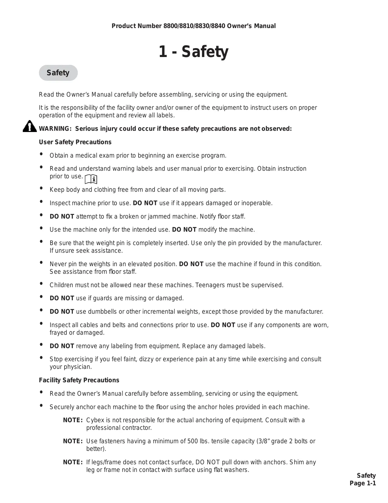
Warning/Caution Decals
Warning decals indicate a potentially hazardous situation, which, if not avoided, could result in death or serious injury.
Caution decals indicate a potentially hazardous situation, which, if not avoided, could result in minor or moderate injury.
The warning and caution decals are shown on the following page. The diagrams following the decals show where each decal is located.
WARNING
SERIOUS INJURY COULD OCCUR IF THESE PRECAUTIONS ARE NOT OBSERVED
- Obtain a medical exam prior to beginning an exercise program.
-
Read and understand warning labels and user manual prior to exercising. Obtain instruction prior to use.
-
Keep body and clothing free from and clear of all moving parts.
- Inspect machine prior to use. DO NOT use if it appears damaged or inoperable.
- DO NOT attempt to fix a broken or jammed machine. Notify floor staff.
- Use the machine only for the intended use. DO NOT modify the machine.
- Be sure that the weight pin is completely inserted. Use only the pin provided by the manufacturer. If unsure seek assistance.
- Never pin the weights in an elevated position. DO NOT use the machine if found in this condition. Seek assistance from floor staff.
- Children must not be allowed near this machine. Teenagers must be supervised.
- DO NOT use if guards are missing or damaged.
- DO NOT use dumbbells or other incremental weights, except those provided by the manufacturer.
- Inspect all cables and belts and connections prior to use. DO NOT use if any components are worn, frayed, or damaged.
- DO NOT REMOVE THIS LABEL. REPLACE IF DAMAGED.
4605-381-4B
CAUTION
Failure to correctly adjust could result in personal injury.
Always fully engage the detent pin before use to avoid injury.
8500-025-4A
CAUTION
Do not rest body weight on stabilization pad or arm.
Doing so may result in personal injury.
8800-442-4A
Description
Part No.
A. Warning Label............4605-381-4
B. Caution Decal. 8500-025-4
C. Caution Decal............8800-442-4
Regular Maintenance Activities
Preventative maintenance activities must be performed to maintain normal operation of your equipment. Keeping a log sheet of all maintenance actions will assist you in staying current with all preventative maintenance activities. The preventative maintenance actions are described in detail in Chapter 5. Briefly, they include:
Daily
- Clean upholstery.
Weekly
- Inspect all nuts and bolts for looseness. Tighten as required.
- Inspect all cables and belts for damage or wear (see Chapter 5). If a cable or belt is worn or damaged, immediately discontinue use until cable or belt has been replaced.
- Check for worn handles, worn snap links, and worn warning labeling. Replace all worn parts immediately.
- Inspect for loose or worn grips. Replace all loose or worn grips immediately.
5 Inspect weight stacks for proper alignment and operation. Correct all improper alignment and operation issues immediately. - Lubricate guide rods using automotive engine oil only.
Yearly
- Replace all cables and belts at least annually.
Using Proper Form
Before working out, read and understand the exercises located on the placard and in Chapter 2.
2 - Exercise
Intended Use
The intended use of this equipment is to aid or improve general physical fitness and exercise. For Commercial use.
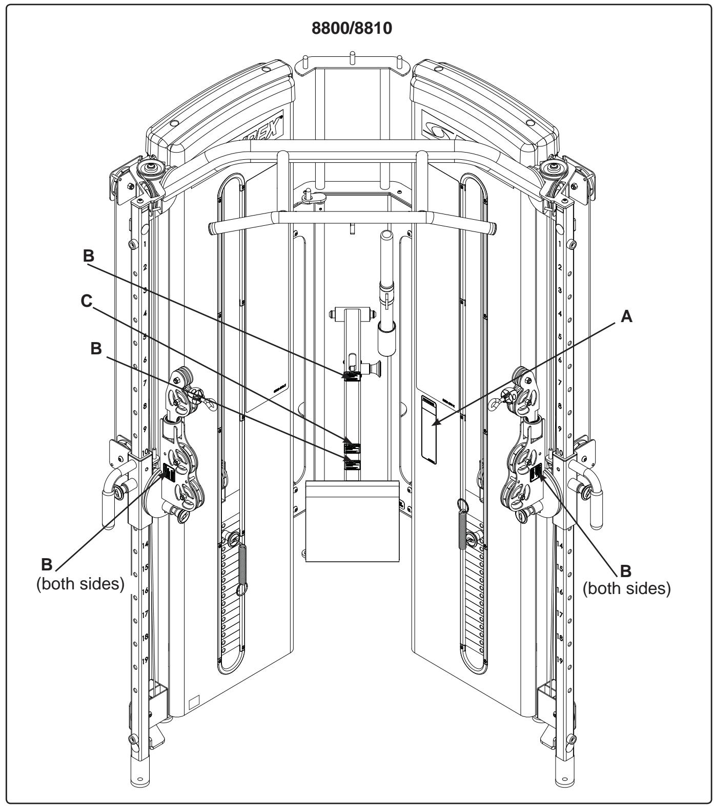
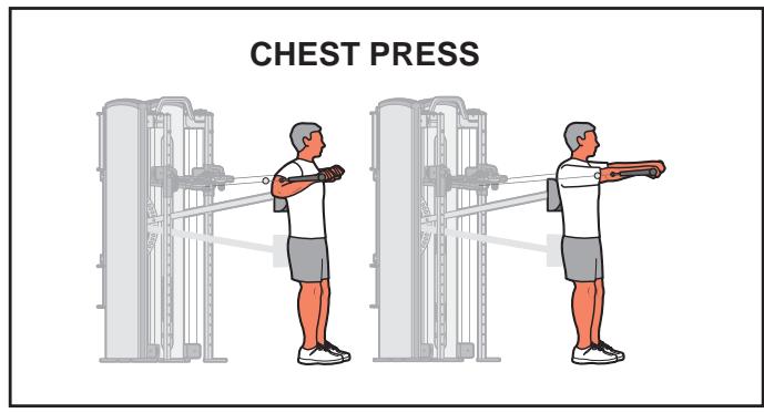
Instructions
Read and understand all instructions and warnings prior to using this machine. See Chapter 1, Safety, in the Owner's Manual or consult with floor staff.
- Select appropriate resistance.
- Adjust handles for proper pulley height.
- Rotate pulleys to desired angle.
- Adjust stabilization arm to desired angle.
- Adjust stabilization pad to desired position.
- Ensure all adjustment knobs are locked into place
NOTE: Position stabilization arm and pad all the way in and all the way down when not in use.
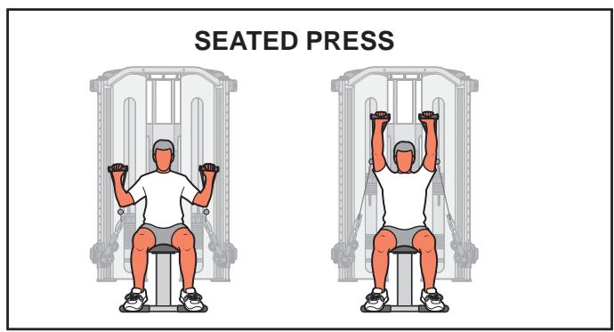
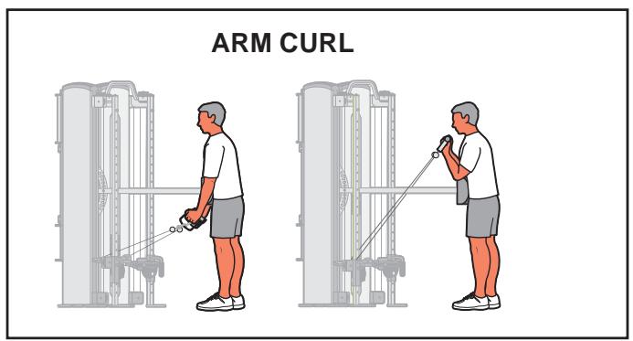
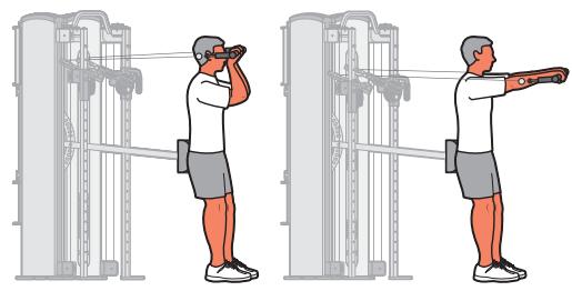
ARM EXTENSION
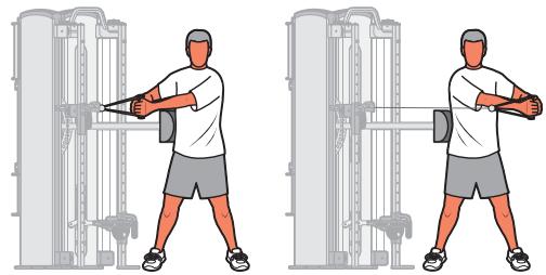
TRUNK ROTATION
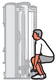
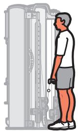
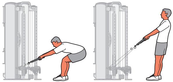
SQUAT
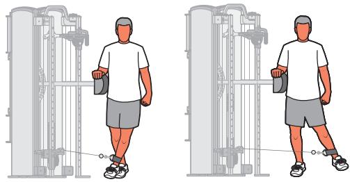
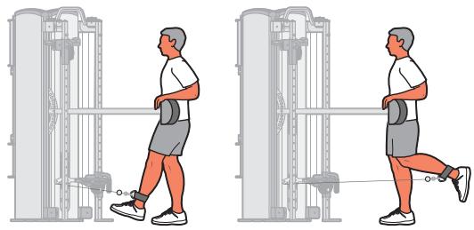
HIP ABDUCTION
HIP ADDUCTION
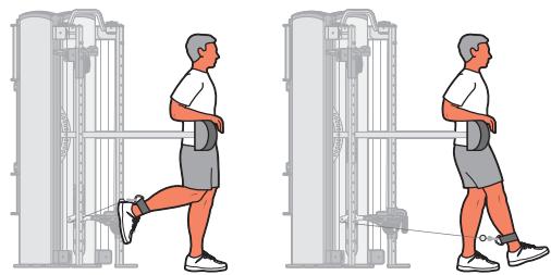
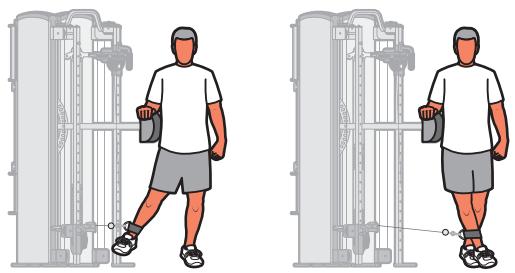
HIP FLEXION-KNEE EXTENSION
HIP EXTENSION-KNEE FLEXION
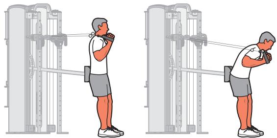
TRUNK FLEXION
TRUNK EXTENSION
3 - Customer Service
Contacting Service
Hours of phone service are Monday through Friday from 8:30 a.m. to 6:00 p.m Eastern Standard Time.
For Cybex customers living in the USA, contact Cybex Customer Service at 888-462-9239.
For Cybex customers living outside the USA, contact Cybex Customer Service at 508-533-4300 or fax 508-533-5183.
Find information on the web at www.cybexintl.com or e-mail at techhelp@cybexintl.com.
Ordering Parts
Fax orders to 508-533-5183. To speak with a customer service representative, call 888-462-9239 (for customers living within the USA) or 508-533-4300 (for customers outside the USA). You may also contact us through e-mail at techhelp@cybexintl.com.
Having the following information ready when calling, will assist our Cybex representatives in serving you.
- Unit Serial Number
Product Name

CAUTION
Use only Cybex replacement parts when servicing. Failure to do so could result in personal injury.
NOTE: All inspections and repairs must be performed by trained service personnel only.
Cybex will void warranty if non-Cybex replacement parts are used.
The unit serial number and product name can be found on the serial number decal.
Part Description
Part Number
Part descriptions and part numbers are located on the web at www.cybexintl.com.
Shipping Address
- Contact Name
In addition to your shipping address and contact name, your account number is helpful but not required.
Return Material Authorization (RMA)
The Return Material Authorization (RMA) system outlines the procedures to follow when returning material for placement, repair or credit. The system assures that returned materials are properly handled and analyzed. Follow the following procedures carefully.
Contact your authorized Cybex dealer on all warranty-related matters. Your local Cybex dealer will request a RMA from Cybex, if applicable. Under no circumstances will defective parts or equipment be accepted by Cybex without proper RMA and an Automated Return Service (ARS) label.
- Call the Customer Service Hot Line listed above for the return of any item that is defective.
- Provide the technician with a detailed description of the problem you are having or the defect in the item you wish to return.
- Provide the model and serial number of your Cybex equipment.
- At Cybex's discretion, the technician may request that you return the problem part(s) to Cybex for evaluation and repair or replacement. The technician will assign you a RMA number and will send you an ARS label. The ARS label and the RMA numbers must be clearly displayed on the outside of the package that contains the item(s) to be returned. Include the description of the problem, the serial number of the equipment and the name and address of the owner in the package along with the part(s).
- Forward the package through UPS to Cybex.
Attn: Customer Service Department
Cybex International, Inc.
1975 24th Ave SW
Owatonna, MN 55060
NOTE: Merchandise returned without an RMA number on the outside of the package or shipments sent COD will not be accepted by the Cybex receiving department.
Damaged Parts
Materials damaged in shipment should not be returned for credit. Shipping damages are the responsibility of the carrier (UPS, Federal Express, trucking companies, etc.)
Apparent Damage - Upon receipt of your shipment, check all items carefully. Any damage seen with a visual check must be noted on the freight bill and signed by the carrier's agent. Failure to do so will result in the carriers refusal to honor your damage claim. The carrier will provide you with the required forms for filing such claims.
Concealed Damage - Damage not seen with a visual check upon receipt of a shipment but notices later must be reported to the carrier as soon as possible. Upon discovery of the damage, a written or phone request to the carrier asking them to perform an inspection of the materials must be made within ten days of the delivery date. Keep all shipping containers and packing materials as they will be needed in the inspection process. The carrier will provide you with an inspection report and the necessary forms for filing a concealed damage claim. Concealed damage claim is the carrier's responsibility. Cybex, if applicable. Under no circumstances will defective parts or equipment be accepted by Cybex without proper RMA and an Automated Return Service (ARS) label.
4 - Assembly
Tools Required
7/32" Allen wrench
3/4" Socket
- Hammer
3/16" Pin punch
9/16" Wrench
Loctite #242
NOTE: Two people will be required to perform this procedure.
NOTE: It is the responsibility of the facility owner/owner of the equipment to ensure that there is appropriate clearance around each machine to allow for safe use and passage.
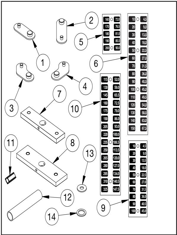
| ITEM | QTY | PART NO. | DESCRIPTION |
| 1 | 2 | 12090-322 | FOOT PAD |
| 2 | 2 | 13000-353 | FOOT PAD |
| 3 | 1 | 13000-355 | FOOT PAD |
| 4 | 1 | 13000-354 | FOOT PAD |
| 5 | 1 | 13000-551 | DECAL, STANDARD (160-200) |
| 6 | 1 | 4800-557 | DECAL, STANDARD (10-150) |
| 7 | 16 | 4700-337 | WEIGHT PLATE (STANDARD) |
| 7 | 9 | 4700-337 | FOR GRADUATED STACK |
| 8 | 15 | 4700-338 | FOR GRADUATED STACK |
| 9 | 1 | 13000-554 | DECAL, GRADUATED (10-100) |
| 10 | 1 | 13000-555 | DECAL, GRADUATED (115-325) |
| 11 | 8 | 12210-352 | PLASTIC INSERT |
| 12 | 2 | 8830-317 | WEIGHT SPACER TUBE |
| 13 | 2 | HS760106 | WASHER, FLAT 1.75 X .688 X .140 |
| 14 | 2 | JS497600 | WASHER 1.19 ID X 1.75 OD X .12 |
| STANDARD STACK ONLY - items 5, 6, 7 (qty - 16), 11, 12, 13 and 14 GRADUATED STACK ONLY - items 7 (qty - 9), 8, 9 and 10 | |||
- Read and understand all instructions thoroughly before assembling this product.
- Verify the appropriate configuration was received:
A. Correct color of machine.
B. Proper weight stack and weight stack decals. Standard Stack - Weight Pack #13000-041 Graduated Stack - Weight Pack #13000-039 and Weight Pack #13000-040
C. Appropriate owner's manual.
D. Warranty sheet.
E. Verify which machine was received 8800 or 8830 (Chin-Up Bar Installed) or 8810 or 8840 (With Chin-Up Bar).
- Move to desired location.
NOTE: If machine is an 8800/8830 and does not fit through doorway proceed to step 10.
NOTE: If machine is an 8810/8840 and does not fit through doorway proceed to step 10J - 10P. Proceed to step 13 to install Chin-Up Bar.
NOTE: If machine is an 8810/8840 install Chin-Up Bar. Proceed to step 13 to install Chin-Up Bar.
- Remove shipping pallet.

WARNING: Use extreme caution when removing shipping pallet. Failure to do so could result in injury.
A. With an assistant, using a 9/16" wrench, carefully remove each lag bolt securing frame to pallet.
B. Carefully place frame on floor.
C. Carefully place rubber feet (supplied with machine) on each foot of the frame.
5. Securely anchor machine to the floor.
A. Securely anchor machine to the floor using the anchor holes provided in each machine.
NOTE: Cybex is not responsible for the actual anchoring of equipment. Consult with a professional contractor.
NOTE: Use fasteners having a minimum of 500 lbs tensil capacity (3/8" grade 2 bolts or better).
NOTE: If legs/frame does not contact surface, DO NOT pull down with anchors. Shim any leg or frame not in contact with surface using flat washers.
6. Install weight plates.
A. Using a 7/32" Allen wrench, remove the two Button Head Socket Cap Screws (BHSCS) securing the top cap to the frame. See Figure 1.
B. Remove top cap and BHSCS and set aside.
C. Carefully lift shroud up and out of machine.
D. Slide spring loaded guide rod cap down guide rod until cap is clear of frame. NOTE: Guide rod cap is spring loaded.
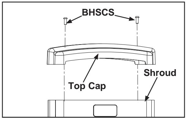
Figure 1
E. Slowly release grasp of guide rod cap. See Figure 2. NOTE: Guide rod cap contains a compression spring that will fly if grasp is not released slowly.
F. Remove guide rod cap and spring and set aside.
G. Repeat steps 6D - 6F for other guide rod.
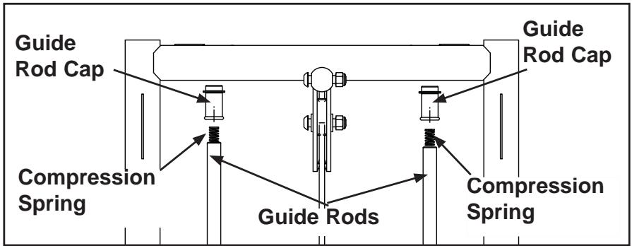
Figure 2
H. Using a 3/16" pin punch and hammer, carefully remove roll pin securing cable end to top weight connector. See Figure 3.
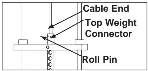
Figure 3
I. Carefully lean guide rods slightly outward. NOTE: Excessive pressure on guide rods may damage lower guide rod caps.
J. Slide top weight up and out of machine and carefully set aside.
K. Have an assistant hold guide rods vertical.
NOTE: Standard Weight Stack only - See steps 6L - 6P and Figures 4 and 7. NOTE: Graduated Weight Stack only - Skip steps 6L - 6P.
L. Slide weight stack bumpers up and out of machine.
M. Install washer (#14) and weight spacer tube (#12) onto each guide rod.
N. Install the four plastic inserts (#11) onto each guide rod. NOTE: The plastic inserts will slide inside the weight spacer tube.
O. Install flat washer (#13) onto each guide rod.
P. Re-install weight stack bumpers.
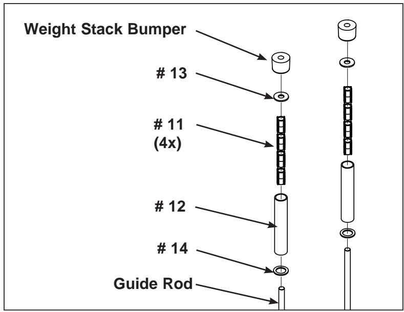
Figure 4
Q. Carefully align weight plates over guide rods and slowly lower each weight plate.
NOTE: When installing weight plates, position plates so wide edges of bushings face upward and narrow edges of bushings face downward. See Figures 5a and 5b.
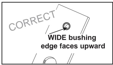
Figure 5a
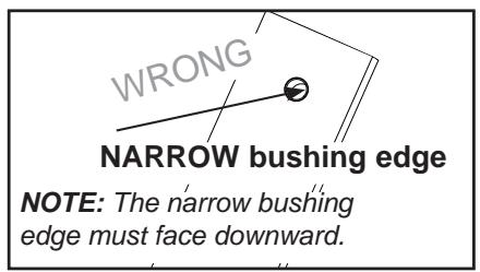
Figure 5b
R. Repeat step 6Q for each weight plate.
S. Carefully slide top weight (removed in step 6J) over guide rods.
7. Install weight plate decals.
NOTE: You have the option to use pounds, kilograms or both.
A. Slowly and carefully peel off back side of decal. See Figure 6. NOTE: When peeling off back cover, make sure that the decals remain attached to the front sticker.
B. Align holes in decal with appropriate holes in weight stack. NOTE: Do not allow the adhesive to touch weight stack at this time.
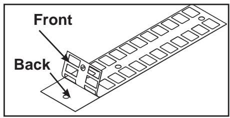
Figure 6
C. Insert a guide pin through each hole of the template. NOTE: A guide pin can be anything that fits through the weight stack hole, such as a weight stack selector pin.
D. Carefully align decal and rub it onto weight plates.
E. Carefully remove front side, leaving decals adhering to weight plates. See Figure 7.
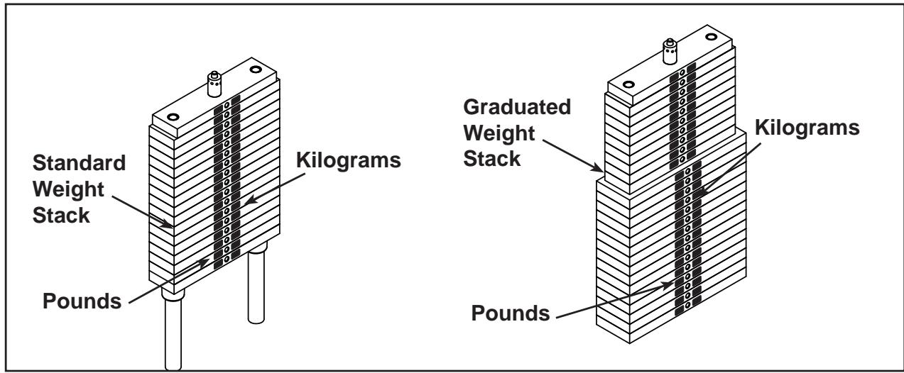
Figure 7
8. Cable routing.
A. Verify cable is routed through top of pulley bracket and then route cable end to top weight connector.
B. Pull cable tight and secure in place with roll pin removed in step 6H.
C. Place weight stack pin in each plate to verify proper installation.
D. Without selecting any resistance, lift top weight up and down (simulating normal operation).
E. Have an assistant verify that the cable is moving smoothly and is routed straight from the pulley bracket to the top of the weight plate connector.
9. Install back shrouds.
A. Carefully place shrouds into position.
B. Secure top cap in place with the two BHSCS removed in step 6A.
10. Separate frame for 8800/8830 (If needed to fit thru doorway).
A. Remove shipping pallet (refer to step 4).
B. Locate insert plug. See Figure 8.
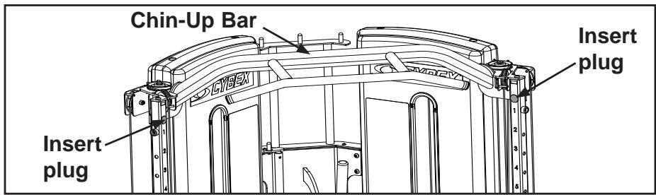
Figure 8
C. Remove insert plug to gain access to BHSCS securing Chin-Up Bar. See Figure 8. NOTE: 8810 /8840 units are not shipped with Chin up bar attached (refer to step 13).
D. Repeat step 10C for insert plug on opposite side.
E. Locate BHSCS on top of frame near pulley. See Figure 9.
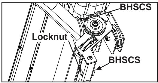
Figure 9
F. Using a 7/32" Allen wrench remove two BHSCS securing Chin-Up Bar
G. Using a 7/32" Allen wrench and socket remove two BHSCS securing Chin-Up Bar.
H. Repeat step 10E and 10F for opposite side
I. Carefully remove Chin-Up Bar and set aside.
J. With an assistant remove 4 (of 8) BHSCS securing frame halves. See Figure 10.
K. Move to desired location.
L. Place both halves of frame together and tightly secure the four BHSCS removed in step 10J.
M. Place a drop of 242 Loctite on BHSCS and threaded hole removed in step 10J.
N. With an assistant secure Chin-Up Bar in place removed in step 10l.
O. Verify all BHSCS are securely tightened.
P. Insert plugs removed in step 10C for 8800/8830 or from hardware pack for the 8810/8840.
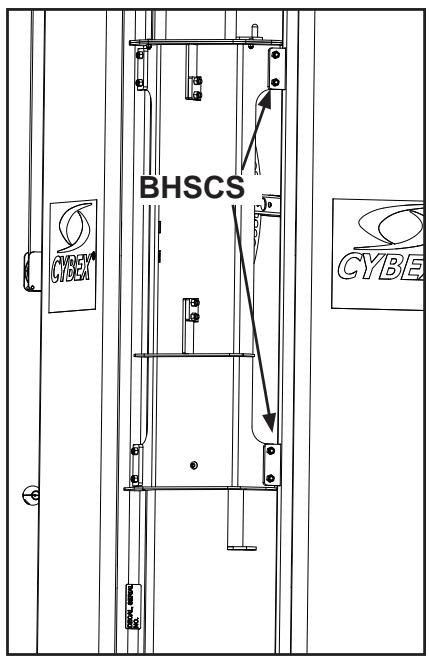
Figure 10
- Install weight plates, decals, cable routing and, shroud assembly for 8800/8830.
A. Refer to step 6A - 9B for weight plates, decals, cable routing, and shroud assembly.
- Separate Frame for 8810/8840 (If needed to fit thru doorway).
A. Remove shipping pallet refer to step 4.
B. Refer to steps 10J - 10N.
- Install Chin Up Bar (8810/8840 units only).
A. Locate Chin Up Bar and hardware.
B. With an assistant, align Chin Up Bar in place.
C. Place a drop of Loctite 242 on BHSCS from hardware bag and threaded holes.
D. Secure Chin Up Bar with hardware from hardware bag.
E. Verify all BHSCS are securely tightened.
F. Carefully slide top weight (removed in step 6J) over guide rods.
G. Insert plugs from hardware bag. NOTE: Refer to step 10B for location of plugs.
- Install weight plates, decals, cable routing and shroud assembly for 8810/8840.
A. Refer to steps 6A - 9B for weight plates, decals, cable routing, and shroud assembly.
15. Verify proper operation.
5 - Maintenance
All preventive maintenance activities must be performed on a regular basis. Performing routine preventive maintenance actions can aid in providing safe, trouble-free operation of all Cybex Strength Systems equipment.
NOTE: Cybex is not responsible for performing regular inspection and maintenance actions for your machines. Instruct all personnel in equipment inspection and maintenance actions and also in accident reporting/recording. Cybex phone representatives are available to answer any questions or concerns that you may have.
CAUTION
Use only Cybex replacement parts when servicing.
Failure to do so could result in personal injury.
NOTE: All inspections and repairs must be performed by trained service personnel only.
Cybex will void warranty if non-Cybex replacement parts are used.
Daily Procedures
- Upholstery - Wipe down all upholstery as per the recommendations listed below for light soiling and more difficult stains.
Light Soiling
A solution of 10% household liquid soap with warm water applied with a soft damp cloth.
- If necessary, a solution of liquid cleanser and water applied with a soft bristle brush. Wipe away the residue with a water dampened cloth.
More Difficult Stains
-ampen a soft white cloth with a solution of 10 % household bleach (sodium hypochlorite), 90 % water. Rub gently. Rinse with a water dampened cloth to remove bleach concentration.
The same procedure can be used with full strength household bleach, if necessary.
- Allow bleach to puddle on the affected area or apply with a soaked cloth for approximately 30 minutes. Rinse with a water dampened cloth to remove any remaining bleach concentration.
Alternative Method for Difficult Stains
-ampen a soft white cloth with rubbing alcohol and rub gently. Rinse with a water dampened cloth to remove any remaining rubbing alcohol concentration.
NOTE: To restore luster, a light coat of spray furniture wax can be used. Apply for 30 seconds and follow with a light buffing using a clean white cloth.
Please Review Carefully
When using strong cleaning agents such as rubbing alcohol or bleach, it is advisable to first test in an inconspicuous area. Other cleaning agents may contain harsh or unknown solvents and are subject to formula changes by the product manufacturer without notice. Should you desire to use other cleaning agents, carefully try them in an inconspicuous area to determine potential damage to the material. Never use harsh solvents or cleaners which are intended for industrial applications. To clean stained or soiled areas, a soft white cloth is recommended. Avoid use of paper towels.
Cleaning products may be harmful/irritating to your skin, eyes, etc. Use protective gloves and eye protection. Do not inhale or swallow any cleaning product. Protect surrounding area/clothing from exposure. Use in well ventilated area. Follow all product manufacturer's warnings. CYBEX and its vendors cannot be held responsible for damage or injuries resulting from the use or misuse of cleaning products.
- Frames - Wipe down all frames using a mild solution of warm water and car wash soap. Be sure to dry thoroughly. AVOID acid or chlorine based cleaners and also cleaners containing abrasives as these could scratch or damage the equipment.
- Chrome - Clean chrome tubes, first using chrome polish and then using a car wax seal. Neutral cleaners with a pH between 5.5 and 8.5 are recommended. Be sure to dry thoroughly. AVOID acid or chlorine based cleaners and also cleaners containing abrasives as these could scratch or damage the equipment.
4. Guidelines for cleaning front panel:
- Use clean soft cloths or sponges for application of cleaners and again for washing and rinsing.
- Follow up the application with warm water rinse.
- Don't use abrasives or high alkaline cleaners.
- Don't leave cleaners on for long periods, wash immediately.
- Don't apply cleaners in direct sunlight or at elevated temperatures.
- Don't use scrapers, squeegees or razors.
- Don't clean with gasoline.
Compatible Cleaners and Detergents:
Formula 409
- Top Job
Joy
Palmolive
- Windex with Ammonia D
To Minimize Fine or Hairline Scratches:
Mild automotive polish applied and removed with a soft, clean cloth will help fill scratches.
Suggested Polishes:
- Johnson Past Wax
- Mirror Glaze #10 Plastic Polish (by Mirror Bright Polish Co.)
- Novus Plastics Polish #1, #2 (By Novus Inc.)
Weekly Procedures
- Check all nuts and bolts for looseness. Tighten as required.
- Inspect all cables for wear or damage and proper tension. When inspecting cables, run fingers on the cable, paying particular attention to bends in cable and attachment points.

WARNING: Replace all worn cables immediately. The following conditions may indicate a worn cable:
- A tear or crack in the cable sheath that exposes the cable. See Figure 1.
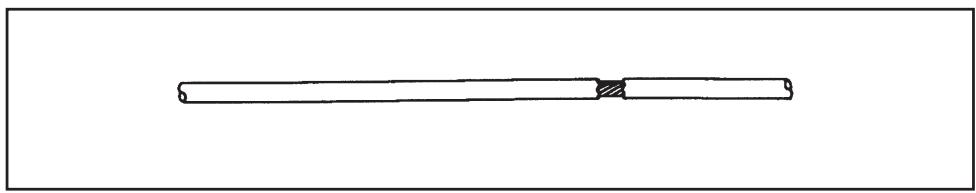
Figure 1.
A kink in the cable. See Figure 2.
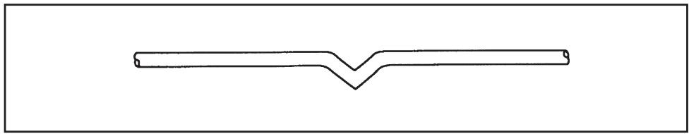
Figure 2.
A curled sheath. See Figure 3.
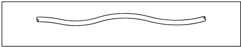
Figure 3.
- "Necking", a stretched cable sheath. See Figure 4.
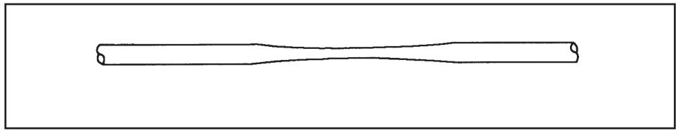
Figure 4.
- Inspect bars and handles for wear, paying particular attention to tab area connection points.
Replace all worn handles immediately.

CAUTION: Replace all worn handles immediately. Do not use if less than 1/8 of material remains to the edge. See Figure 5.
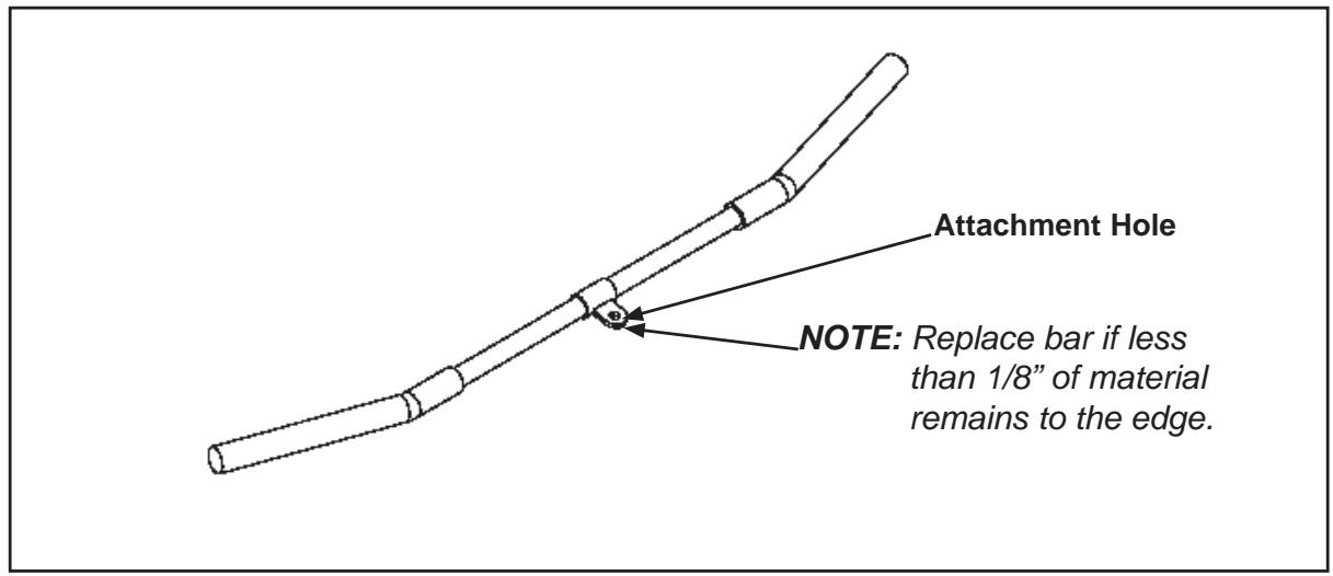
Figure 5
- Inspect snap links for proper latching (indicates wear)
Replace all worn snap links immediately.
- Inspect for loose or worn grips.
Replace all loose or worn grips immediately.
- Inspect all labeling for readability. This includes instructional placards, warning and caution decals.
Replace all worn labeling immediately.
- Inspect all weight stacks for proper alignment and operation.
Correct all improper alignment and operation issues immediately.
- Wipe Weight Stack Guide Rods clean over entire length. Lubricate with a light coat of medium weight automotive engine oil.
Yearly Procedures
- Replace all cables at least annually.
Cable Adjustment
Three types of cable tension adjustment are used on Cybex Strength Systems:
- Jam Nut Adjustment - This type uses a jam nut and a tension adjustment nut at the cable cam end as the primary adjustment. The other end of the cable usually contains a roll pin adjustment. See Figures 6 and 7.
- Rod End Adjustment - This type of adjustment contains a socket head cap screw (SHCS) securing a cable rod end bearing to the machine. Primary adjustment is by turning the rod end bearing. The other end of the cable usually contains a roll pin cable adjustment. See Figures 7 and 8.
- Roll Pin Adjustment - This type of adjustment utilizes a roll pin and series of holes in the weight stack top weight connector. See Figure 8.
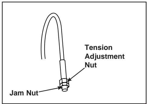
Figure 6
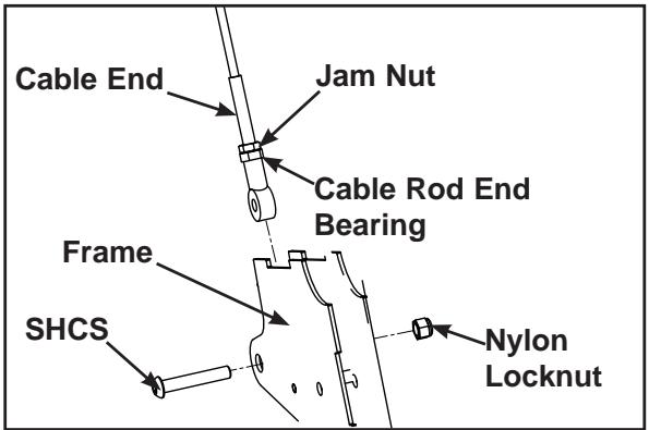
Figure 7
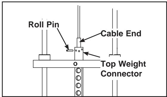
Figure 8
Environment
Humidity and Static Electricity
The unit is designed to function normally in an environment with a relative humidity range of 30% to 75% . The unit can be shipped and stored in a relative humidity range of 10% to 90% .
Climatic dry air may cause static electricity. During workout, user may experience a shock due to build-up of static electricity on the body and the discharge path of the unit. If static electricity is experienced, increase humidity to a comfortable level through the use of a humidifier.
NOTE: Do not install or use the unit in an area of high humidity, such as in the vicinity of a steam room, sauna, indoor pool or outdoors. Exposure to extensive water vapor, chlorine and/or bromine could adversely affect parts of the machine.
Temperature - The unit is designed to function normally in an environment with an ambient temperature range of 50^ ( 10^ ) to 104^(40^) degrees.
Storage
Humidity - The unit can be shipped and stored in an environment with a relative humidity range of 10% to 90% .
NOTE: Do not store the unit in an area of high humidity, such as in the vicinity of a steam room, sauna, indoor pool or outdoors. Exposure to extensive water vapor, chlorine and/or bromine could adversely affect the electronics as well as other parts of the machine.
Temperature - The unit can be shipped and stored in an environment with an ambient temperature range of 32^ ( 0^ ) and 140F ( 60^ ) degrees.
This page intentionally left blank.