
425A ARC - Fitness Equipment CYBEX INTERNATIONAL - Free user manual and instructions
Find the device manual for free 425A ARC CYBEX INTERNATIONAL in PDF.

| Product type | Fitness equipment |
| Brand | CYBEX INTERNATIONAL |
| Model | 425A ARC |
| Dimensions | Approximately 200 x 80 x 170 cm |
| Weight | Approximately 150 kg |
| Power supply | Mains 220-240 V |
| Main functions | Cardiovascular training with natural elliptical motion, varied training programs |
| Maintenance and cleaning | Regular cleaning with a damp cloth, lubrication of moving parts as per the manual |
| Safety | Emergency stop button, mandatory supervision of children and persons with disabilities |
| Spare parts and repairability | Spare parts available on request from the manufacturer |
| General information | Professional use in gyms, compliant with safety standards |
Frequently Asked Questions - 425A ARC CYBEX INTERNATIONAL
User questions about 425A ARC CYBEX INTERNATIONAL
0 question about this device. Answer the ones you know or ask your own.
Ask a new question about this device
Download the instructions for your Fitness Equipment in PDF format for free! Find your manual 425A ARC - CYBEX INTERNATIONAL and take your electronic device back in hand. On this page are published all the documents necessary for the use of your device. 425A ARC by CYBEX INTERNATIONAL.
USER MANUAL 425A ARC CYBEX INTERNATIONAL
Part Number 5425A-4 T

Cybex Arc Trainer® 425A
Owner's Manual
Cardiovascular Systems
Part Number 5425A-4 T
Cybex® and the Cybex logo are registered trademarks of Cybex International, Inc.
Arc Trainer® and its mark are registered trademarks of Cybex International, Inc.
Polaris® a registered trademark of Polar.
DISCLAIMER: Cybex International, Inc. makes no representations or warranties regarding the contents of this manual. We reserve the right to revise this document at any time or to make changes to the product described within it without notice or obligation to notify any person of such revisions or changes.
© 2010 Cybex International, Inc. All rights reserved. Printed in United States of America.
10 Trotter Drive Medway, MA 02053 · 888-426-9239 · 508-533-4300 · FAX 508-533-5183
www.cybexinternational.com • techhelp@cybexintl.com • techpubs@cybexintl.com • 5425A-4 T • May 2010
About This Manual
An Owner's Manual is shipped with each unit. To purchase additional copies of this manual or any other Cybex manual, please do one of the following:
- fax orders to 508-533-5183 or contact Cybex Customer Service at 888-462-9239
- or contact Cybex Customer Service at 508-533-4300.
Find information on the web at www.cybexinternational.com or by e-mail at techhelp@cybexintl.com.
FCC Compliance Information
! WARNING: Changes or modifications to this unit not expressly approved by the party responsible for compliance could void the user's authority to operate the equipment.
This equipment has been tested and found to comply with the limits for a Class B digital device, pursuant to Part 15 of the FCC Rules. These limits are designed to provide reasonable protection against harmful interference in a residential installation. This equipment generates, uses and can radiate radio frequency energy and, if not installed and used in accordance with the instructions, may cause harmful interference to radio communications. However, there is no guarantee that interference will not occur in a particular installation. If this equipment does cause harmful interference to radio or television reception (which can be determined by turning the equipment off and on) the user is encouraged to try to correct the interference by one or more of the following measures:
- Reorient or relocate the receiving antenna.
- Increase the separation between the equipment and receiver.
- Connect the equipment into an outlet on a circuit different from that to which the receiver is connected.
- Consult the dealer or an experienced radio TV technician for help.
Table of Contents
Front Pages
About this Manual
FCC Compliance information.
Table of Contents..
1 Safety
Important Voltage Information. 1-1
Grounding Instructions. 1-1
Important Safety Instructions. 1-2
Warning Decals. 1-4
2 Technical Specifications
Specifications 2-1
3 Operation
Terms and Symbols Used. 3-1
Quick Operation Guide 3-2
Detailed Operation Guide 3-2
Stopping the Arc Trainer 425A. 3-5
Presence Detect 3-5
Control During Operation. 3-5
Data Readouts. 3-6
Displaying Heart Rate. 3-7
Heart Rate LED 3-7
Use of Programs. 3-8
Manual Mode 3-9
The Workout Profile 3-9
Range of Motion 3-9
Speed Interval 1. 3-11
Speed Interval 2. 3-13
Hills Interval 3-14
Valleys. 3-16
Ramps. 3-18
Hills 3-20
Weight Loss 3-22
Cardio 3-24
4 Preventive Maintenance
Warnings 4-1
Regular Maintenance Activities. 4-1
Cleaning Your Arc Trainer 425A. 4-2
Drive Belt Maintenance. 4-3
Lubrication 4-4
Environment. 4-4
Storage 4-4
5 Setup and Assembly
Warnings/Cautions. 5-1
Choosing and Preparing a Site. 5-1
Electrical Power Requirements. 5-2
Assembling the Arc Trainer 425A............5-2
Testing the Operation. 5-10
Setting Operation Options 5-11
6 Customer Service
Contacting Service. 6-1
Serial Number and Voltage. 6-1
Return Material Authorization (RMA) 6-2
Damaged Parts. 6-3
Ordering Parts 6-3
Parts List - Main Assembly 6-4
Exploded View - Main Assembly 6-5
Exploded View - Main Assembly 6-6
Exploded View - Main Assembly 6-7
Parts List - Console Assembly. 6-8
Exploded View - Console Assembly 6-9
Parts List - Drive Frame Assembly 6-10
Exploded View - Drive Frame Assembly ....6-11
Schematic 6-13
1 - Safety
IMPORTANT: Read all instructions and warnings before using the unit.
Important Voltage Information
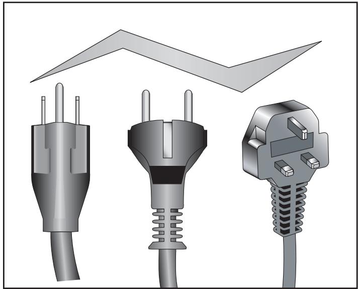
Before plugging the power cord into an electrical outlet, verify that the voltage requirements for your area match the voltage of the unit that you have received. The power requirements for the unit include a grounded circuit, rated for one of the following: 115 VAC ± 5%, 50/60 Hz and 15 amps; or 230 VAC ± 10%, 50/60 HZ and 10 amps. See the voltage requirement decal for the exact voltage requirements of your unit.

WARNING: Do not attempt to use this unit with a voltage adapter. Do not attempt to use this unit with an extension cord.
Grounding Instructions
This unit must be grounded. If it should malfunction or break down, grounding provides a path of least resistance for electric current to reduce the risk of electric shock. This product is equipped with a cord having an equipment-grounding conductor and a grounding plug. The plug must be plugged into an appropriate outlet that is properly installed and grounded in accordance with all local codes and ordinances.
AW-19624
115 VAC
AW-19627
100 VAC
AW-19625
230 VAC
AW-19626
230 VAC

DANGER: Improper connection of equipment grounding conductor can in a risk of electric shock. Check qualified electrician or service worker if you are in doubt as to whether it is properly grounded. Seek a qualified electrician to perform any locations to the cord or plug. Cybex is responsible for injuries or damages as well as of cord or plug modification.
This unit is for use on a nominal 115 VAC ^+ 5% , 50/60 Hz and 15 amps; or 230 VAC ^+ 10% , 50/60 Hz and 10 amps and a grounded circuit. Make sure that the unit is connected to an outlet having the same configuration as the plug. Do not use a ground plug adapter to adapt the power cord to a non-grounded outlet.
Important Safety Instructions
(Save These Instructions)

DANGER: To reduce the risk of electric shock, always unplug this unit from the electrical outlet immediately after using it and before cleaning it.

WARNING: Serious injury could occur if these precautions are not observed. To reduce the risk of burns, fires, electric shock, or injury:
User Safety Precautions
- Keep children away. Teenagers and disabled must be supervised. Tenez les enfants éloignés. Les adolescents et les handicapés doivent être surveilles.
- Obtain instruction before using. Lisez les instructions avant l'utilisation.
- Wait until foot plates come to a complete stop before dismounting. Attendre l'arret complet des reposes pieds avant de descendre.
- Obtain a medical exam before beginning any exercise program.
- Stop exercising if you feel faint, dizzy, or experience pain.
- Read and understand the Owner's Manual and all warnings posted on the unit before using.
DO NOT wear loose or dangling clothing while using. - Keep all body parts, towels, and the like free and clear of moving parts.
Use the handles for support and to maintain balance.
DO NOT use the unit if you exceed 350 lbs. (160 kg). This is the rated maximum user weight. - Replace any warning labels if damaged, worn or illegible.
Report any malfunctions, damage or repairs to the facility.
Facility Safety Precautions
Make sure all user and safety precautions are observed.
- Read and understand the Owner's Manual completely before using the unit.
- Make sure all users are properly trained on how to use the equipment.
- Make sure that each machine is set up and operated on a solid level surface. Do not install equipment on an uneven surface.
Cybex Arc Trainer 425A Owner's Manual
- Make sure there is enough room for safe access and operation of the equipment.
- Perform regular maintenance checks on the equipment. Also pay close attention to all areas most susceptible to wear, including (but not limited to) cables, pulleys, belts and grips.
- Immediately replace worn or damaged components. If unable to immediately replace worn or damaged components then remove from service until the repair is made.
- Do not attempt repairs, electrical or mechanical. Seek qualified repair personnel when servicing. If you live in the USA, contact Cybex Customer Service at 888-462-9239. If you live outside the USA, contact Cybex Customer Service at 508-533-4300.
- Disconnect all power before servicing the unit.
- Keep a repair log of all maintenance activities.
- Use only Cybex supplied components to maintain/repair the equipment.
- Do not use attachments unless recommended for the unit by Cybex.
- Do not operate the unit if: (1) the cord is damaged; (2) the unit is not working properly or (3) if the unit has been dropped or damaged. Seek service from a qualified technician.
- Do not operate electrically powered units in damp or wet locations.
- Do not operate the unit around or where aerosol (spray) or where oxygen products are being used.
- Do not use the unit outdoors.
NOTE: It is the sole responsibility of the user/owner or facility operator to ensure that regular maintenance is performed.

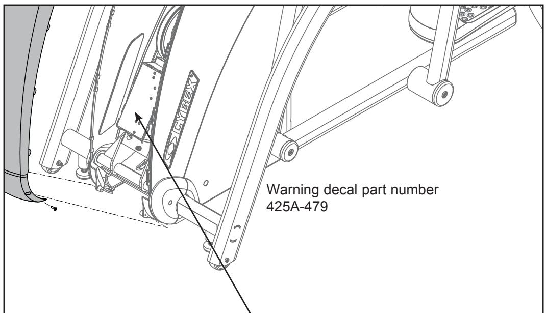
Warning Decals
Carefully read and understand the following before using the unit:
NOTE: To replace any worn or damaged decals do one of the following: Fax orders to 508-533-5183 or contact Cybex Customer Service at 888-462-9239. If you live outside of the USA, call 508-533-4300.
Warning decals indicate a potentially hazardous situation, which, if not avoided, could result in death or serious injury. The warning decals are shown below.
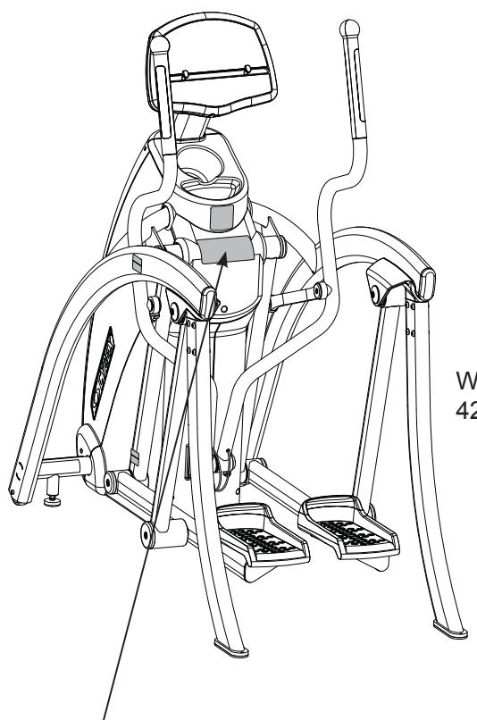
Warning decal part number 425A-495-4

WARNING
Read and understand the Owner's Manual and all warnings posted on the unit before using.
SERIOUS INJURY COULD OCCUR IF THESE PRECAUTIONS ARE NOT OBSERVED
Obtain instruction before using. Lisez les instructions avant l'utilisation.
Wait until foot plates come to a complete stop before dismounting.
Attendre l'arret complet des
reposes pieds avant de descendre.
Obtain a medical exam before beginning any exercise program.
Stop exercising if feeling faint, dizzy, or experiencing pain.
Keep foot plate surface clean and dry.
DO NOT wear loose or dangling clothing while using.
Keep all body parts, towels, and the like free and clear of moving parts.
Use handles for support and to maintain balance.
DO NOT use unit if user exceeds 350 lbs. (160 kg). This is the rated maximum user weight.
Replace any warning labels if damaged, worn or illegible.
Report any malfunctions, damage or repairs to the facility. 425A-495-4 B
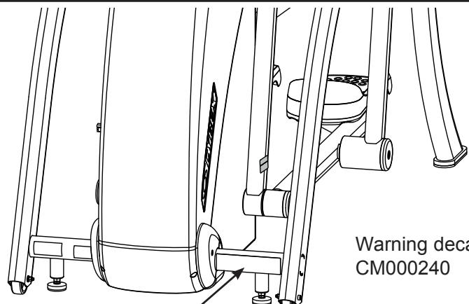
Warning decal part number
CM000240

WARNING
AVERTISSEMENT
DISCONNECT DÉBRANCHEZ
POWER L'ALIMENTATION SERVICEAR
Warning decal part number
DE-17219-4 (Both Sides)

CAUTION
Moving parts.
Keep hands away
when in use.
DE-17219-4 B
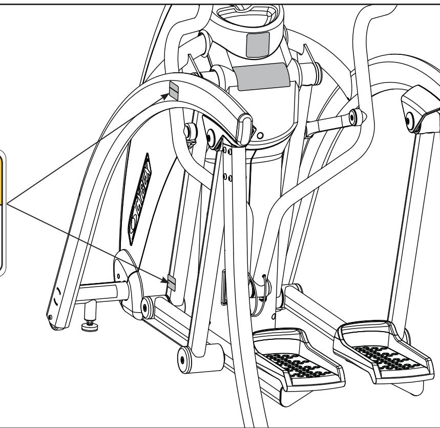


All maintenance activities must be performed by qualified personnel. Failure to do so could result in serious injury.
2 - Technical Specifications
Specifications
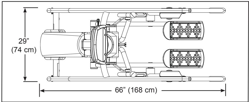
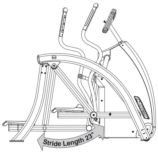
Length: 66" (168 cm).
Width: 29" (74 cm).
Height: 40" (102 cm).
Weight of Product: 380 lbs. (204 kg).
Shipping Weight: 420 lbs. (215 kg).
Incline Levels: 11 (Represented by 0-10 in increments of 1).
Resistance Levels: 81 (Represented by 0 - 80% in increments of 1).
Stride Length: 23" (58 cm) fixed length.
Programs: Quick Start plus Manual, Weight Loss, Cardio, Speed Interval 1, Speed Interval 2, Hills Interval, Valleys, Ramps, Hills and Calorie Goal.
Console Features: Upper console: Dot Matrix of program, large .62" LED display of distance, calories, calories per hour, METS, Watts, strides per minute and heart rate. Lower Console: LED display of resistance and dual function display of time and incline.
Heart Rate Features: Built-in wireless heart rate receiver (transmitter not included) and contact heart rate monitoring.
Frame Colors: Standard: White texture, black texture, metallone gold, black chrome, platinum sparkle.
Custom: Unlimited colors available.
Resistance Range: 600 watt.
Maximum User Weight: 350 lbs. (160 kg).
Power Rating: 115 VAC 50/60 Hz 2A (230 VAC 50/60 Hz 1 amp).
Outlet Rating: 4 amps (or 5 amps outside of the United States).
Power Requirement: A grounded circuit and one of the following:
- 115 VAC ±5%, 50/60 Hz and 15 amps,
- 230 VAC ±10%, 50/60 Hz and 10 amps.
Options: Channel and volume controls on lower switch membrane for embedded A/V.
This page intentionally left blank
3 - Operation
Read and understand all instructions and warnings prior to using the Unit. See all of the safety related information located in chapter 1.
Terms and Symbols Used
This section lists some of the common terms and symbols used in this chapter. Other terms and symbols are listed in this chapter as appropriate.
Dormant Mode - This occurs when the unit is plugged in and not in use. The control panel will display a beating heart when the unit is in Dormant Mode.
Program Setup Mode - This begins after pressing any program key. Upon entering a program the LEDs flash, prompting the user to adjust the appropriate settings.
Active Mode - This begins immediately after pressing the Quick Start key (Manual Mode), or after the Program Setup Mode. The beginning of Active Mode is marked by the 3 second countdown. Active Mode continues until you reach the end of a program or press the Pause/end key.
Quick Start - This begins by pressing the Quick Start key. Quick Start skips the Program Setup Mode and begins immediately in Manual Mode.
Manual Mode - This begins immediately after pressing the Quick Start key or after pressing the Manual program key. In Manual Mode you can customize your workout Resistance and Time and enter your Weight by pressing those keys. NOTE: Manual Mode features differ from the Manual Program. See the Manual section in this chapter.
Workout Review - This begins after pressing the Pause/end key once, at the end of a program or when you stop striding for 25 seconds. The workout statistics accumulated during the previous workout session will display for 20 seconds (default setting) or until Pause/end is pressed again. NOTE: You can change the 20 second default. See Setting Operation Options in chapter 5.
Pause Mode - This begins when the you stop striding for 25 seconds or when you press Pause/end once. While in Workflow Review you can press the Quick Start key to resume your workout in Manual Mode. The time, calories burned and other accumulated data is remembered and added to.
V- These keys adjust Time, Level or Weight up or down.
V- These keys adjust Incline higher or lower...
-
-
- These keys adjust Resistance up (+) or down (-).
-
Quick Operation Guide
NOTE: Maximum user weight is 350 lbs. (160 kg).
The following is a quick overview of the operation of the unit. For more information read Detailed Operation Guide in this chapter. NOTE: Times specified in this chapter reflect the unit's defaults. To change the defaults see Setting Operation Options in chapter 5.
- Hold the handles to steady yourself while you step into the foot plates.
- Press any program key to enter a program or press Quick Start to skip the settings and begin.
- If you pressed a program key to select a program, you will now be prompted for workout Time, Weight, and Level as appropriate. Adjust these settings with the V arrows and press Enter to proceed. IMPORTANT: Enter your actual weight. The Resistance + - keys calculate the proper resistance for your weight. Your workout may feel too easy or too difficult if you do not enter your actual weight.
- The unit begins a countdown, "3...2...1" then the resistance increases to correspond to the program that you selected.
- Begin striding.
- Press the Resistance + - keys to change the load at any time. The right display will show the current resistance setting.
- Press the Incline keys to change the incline at any time. The left display will show the current incline setting.
- Press the Pause/End key at any time.

WARNING: Wait until all moving parts come to a complete stop before dismounting.
- Wait until foot plates come to a complete stop before dismounting the unit. Hold the handles to steady yourself while you step off the unit.
Detailed Operation Guide
NOTE: Maximum user weight is 350 lbs. (160 kg).
- Plug the power cord into a power outlet on a grounded circuit, rated for one of the following: 115VAC-^+5% , 50/60Hz and 15 amps; or 230VAC-^+10% , 50/60Hz and 10 amps.
-
Hold the handles to steady yourself while you step into the foot plates.
-
You now have the option to select a program or to select Quick Start, skip Program Setup Mode, and enter Manual Mode.
To select a program, press the program key and continue pressing until program desired is displayed. Upon entering a program the LEDs flash, prompting you to adjust the appropriate settings. This is referred to as Program Setup Mode. If the Quick Start key is pressed now, all defaults for that program will be accepted. After 10 seconds, if no key has been pressed, the first default will be accepted. After another 10 seconds the second default will be accepted and so on until the last default. The program will not enter Active Mode until you press the Enter or Quick Start key. If no key has been pressed for 20 seconds after displaying the last default, then the unit will return to the Dormant Mode.
If you press the Quick Start key instead of choosing a program, you will enter Manual Mode. NOTE: No prompts will occur in Manual Mode. While in Manual Mode, customize your workout Resistance and Incline and enter your Weight by pressing those keys.
IMPORTANT: Enter your actual weight. The Resistance + - keys calculate the proper resistance for your weight. Your workout may feel to easy or too difficult if you do not enter your actual weight. For the most accurate calorie count, you must set your correct weight before beginning your workout (including clothing).
NOTE: Press Enter after each adjustment.
When you enter Program Setup Mode or Manual Mode the unit will rock slightly. This ensures free movement of the unit.
- The unit begins a countdown, "3...2...1" and sounds a tone for each count. When it reaches one (1)
it gives a longer tone. Depending on which program and level you selected, the resistance may begin to increase and the incline may rise or fall.
- Observe the four displays. (See Figure 1):
The lower left display flashes the actual incline until the desired incline is reached and then reverts to time. During your workout the time will show in the format of minutes:seconds. If your workout exceeds sixty minutes the time format will change to minutes only.
The lower right display shows the user's current resistance.
The top center display begins showing your program profile at the left side.
The center display shows statistics or adjustable settings. This scans (every three seconds) through Distance, Calories, Calories per Hour, Mets, Watts and Strides Per Minute. Press the Scan key to toggle this feature on or off.
NOTE: Heart Rate is scanned only when you are holding the contact heart rate grips or using Polar compatible heart rate transmitter. See Figure 1.
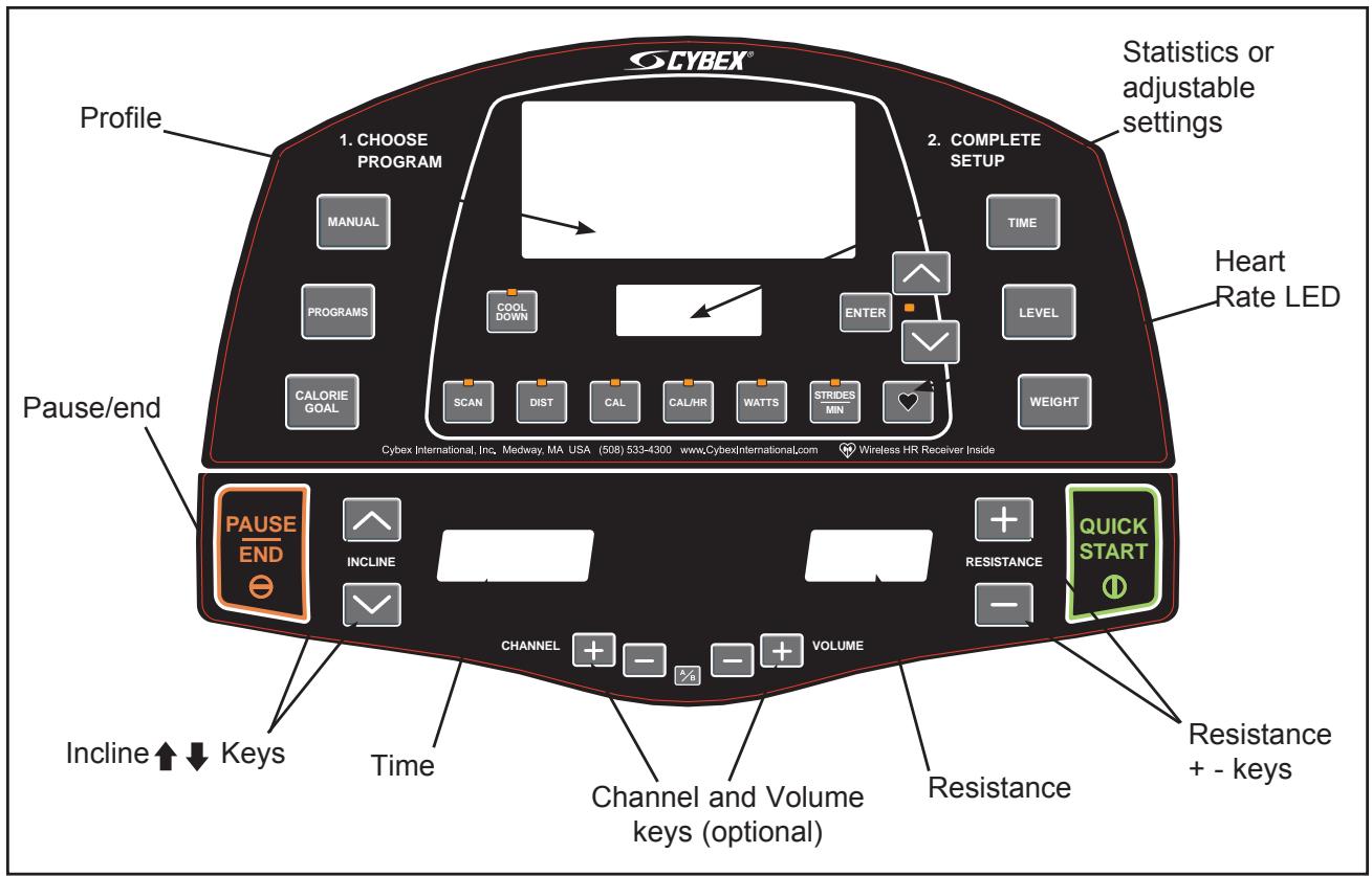
Figure 1 (AV Option)
- Press the Resistance + - keys to change the load at any time. Pressing the + key will make your workout harder. Pressing the - key will make your workout easier. The right display will show the current level in increments of 1 from 0 to 80.
- Press the Incline V keys to change the incline at any time. The left display will show the current incline (only while it is adjusting), in increments of 1 from 0 to 10.
- Press the Pause/end key at any time to stop your workout. Press Pause/end once to end your workout and begin your Workout Review. As you press Pause/end once, the unit will return to level 0 incline (starting position). Press Pause/end twice to clear the Workout Review and return to Dormant Mode.
- When you complete a program the unit begins a countdown, "3...2...1" and sounds a tone for each count. Workout Review displays for 20 seconds (default setting) or until you press the Pause/end key.
NOTE: Speeding up and slowing down is dependent on the user speeding up and slowing down.

WARNING: Wait until foot plates come to a complete stop before dismounting.
- Wait until foot plates come to a complete stop before dismounting the unit. Hold the handles to steady yourself while you step off the unit.
- The unit returns to Dormant Mode.
Stopping the Arc Trainer 425A
Press Pause/End once to pause your workout for 20 seconds (default setting) and to enter the Workflow Review. As you stop striding the foot plates will stop and the elevation will return to the level 0 incline (starting position), but all workout settings and data will remain in memory for the pre-selected time. Press the Quick Start key within the default setting to continue your workout. If the Quick Start key has not been pressed during the 20 seconds pause, workout data will be cleared and the display will change to Dormant Mode.
Press Pause/end a second time to interrupt workout data from cycling and to change the display to Dormant Mode.
NOTE: Speeding up and slowing down is dependent on the user speeding up and slowing down.

WARNING: Wait until foot plates come to a complete stop before dismounting.
Emergency Dismount: Follow the steps listed below if you experience pain, feel faint or need to stop your unit in an emergency situation:
- Grip handles for support.
- Stop striding.
- Wait until the foot plates come to a complete stop.
- Continue holding the handles while you step off the unit.
Presence Detect
Presence Detect uses the movement of the pedals and any input from the user (such as a key press or heart rate) to determine your presence. If you step off the Arc or stop moving during a workout, it may detect that you are not there. After the pre-selected waiting period "run?" will appear in the center window for a few seconds then Presence Detect will end your workout session. If you press Quick Start within the time selected you can resume your workout.
Control During Operation
Control keys on the display are usable during operation and may be pressed at any time to make adjustments in level, incline or data readouts.
Changing Level - You can change the level during a programmed workout. Press the Level key to display the current program and level status. Then press V keys to change the level. The level will change immediately and will continue to accumulate performance data without interruption. NOTE: If you change the level during the Manual Mode the level and resistance will change at once.
Changing Resistance - Press the Resistance + - keys to change the load in increments of 1. Minimum to maximum resistance is from 0-80. NOTE: During a Manual Mode or Quick Start workout the V keys temporarily revert to resistance keys.
Changing Incline - Press the Incline keys to change the elevation in increments of 1 from 0-10. The elevation rises in the shape of an arc ranging from 12 to 34.5 degrees. See Range of Motion in this chapter.
Changing Programs - When changing programs, your data from the previous program will transfer only when changing from one program to Manual Mode. You cannot transfer data when changing from one program to another program or from Manual Mode to a program.
Changing Workflow Time - Press Time to alter the amount of time you plan to workout. You can change Time before or during a workout. NOTE: The Max default time may limit your time. See Setting Operation Options in chapter 5.
Changing Data Readouts - Press Scan once to continue to display a set of data. Press Scan again and it will continually review each set of data. NOTE: The automatic scan is a feature that can be toggled and/or turned on or off. See Setting Operation Options in chapter 5. If Scan is off, your heart rate will still appear when a heart beat is detected.
Data Readouts
As you exercise, the Arc Trainer 425A keeps track of the following data:

Distance - The total accumulated distance, in miles or kilometers, during your workout. NOTE: Depending on the defaults you've chosen this measurement will show in English or Metric.
Calories - The total accumulated calories burned during your workout. Your weight must be correctly set before beginning your workout for this measurement to be most accurate.
Calories Per Hour - Calculation of present workloads energy exertion in Calories per Hour. Your weight must be correctly set before beginning your workout for this measurement to be most accurate.
Metabolic Equivalent - Relates to the user's energy expenditure. A MET is a basic unit of measurement that is used to compare relative work between individuals and activities. One MET is the amount of oxygen an individual consumes at rest. For example two mets would be twice that amount. If an individual were working at four METs he/she would be consuming oxygen at a rate equal to four times their resting consumption. METs can be used to compare walking on a grade with running or even to cycling and other activities. See The Workout Profile in this chapter for more information.
Watts - Present workload energy exertion in Watts.
Strides Per Minute - Your average number of strides per minute at your current speed.
Heart Rate - Your current heart rate. Heart rate will appear when a signal is introduced. Use either the handgrips for Contact Heart Rate or a Polar compatible heart rate transmitter. See Heart Rate LED for a description of colors.
To review accumulated data after a program: The display automatically cycles through your accumulated workout data during the Workout Review for 20 seconds (default setting). NOTE: Heart rate is not displayed during a Workout Review.
Displaying Heart Rate
In order to display your heart rate, you must either use a Polar compatible heart rate transmitter belt (not included) or hold the handgrips to use Contact Heart Rate.
Contact Heart Rate - Hold the handgrips on the handles until a heart rate is displayed, typically less than thirty seconds. For best results, hold the handgrips lightly and ensure that your hands contact both the front and back sensors of each grip. NOTE: Hold your hands as steady as possible as movement can cause interference on the contacts.
Factors that can interfere with the heart rate signal include:
excessive movement
- body composition
- hydration
too loose grip
too tight grip
excessive dirt, powder or oil
- resting or leaning on the grips
Contaminants, such as hand lotions, oils or body powder, may come off on the contact heart rate grips. These can reduce sensitivity and interfere with the heart rate signal. Therefore, ensure you have clean hands when using the contact heart rate.
Polar Compatible Reception - To use this feature, a Polar compatible heart rate transmitter belt must be worn. To view heart rate continuously, press the Scan key when the Heart LED is lit or press the Heart key.
Heart Rate LED
When the handgrips are held the center display switches to show the heart rate in beats per minute (BPM) if you are not scanning. For several seconds the display will show “---”. Once the actual heart rate is determined the center window displays the BPM and the Heart LED lights up. See Figure 2. The color of the light represents a scale of low to high target heart rate.
Blue = 0 - 69 beats per minute
Green = 70-93 beats per minute
Yellow = 94-120 beats per minute
Amber = 121-170 beats per minute
Purple = 171 & up beats per minute
NOTE: A label is on the unit to remind you what the color represents while you are working out. See Figure 2.
Use of Programs

WARNING: Obtain a medical exam before beginning any exercise program. Begin comfortably with a lower level and progress with higher levels as you become acclimated.
With the Arc Trainer 425A, you may choose from nine different programs. Eight of the programs provide ten levels of difficulty for a choice of 80 different
pre-programmed options. You may also use Manual Mode. With this unique combination of programs, you can tailor your workout to achieve exactly the fitness goals you desire, including: weight loss, conditioning, endurance or maintenance of overall health. Speed is never predetermined for you; you can change your speed simply by changing your stride. The program choices are summarized as follows:
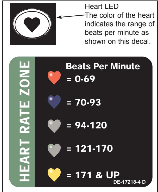
Figure 2
Manual Mode Enter time and weight. You control speed, elevation.
P1 Speed Interval 1 10 Levels Select time, level and weight.
P2 Speed Interval 2 10 Levels Select time, level and weight.
P3 Hills Interval 10 Levels Select time, level and weight.
P4 Valleys 10 Levels Select time, level and weight.
P5 Ramps 10 Levels Select time, level and weight.
P6 Hills 10 Levels Select time, level and weight.
P7 Weight Loss 10 Levels Select time, level and weight.
P8 Cardio 10 Levels Select time, level and weight.
Calorie Goal Enter calorie goal 50 - 2,000.

Manual Mode
Manual Mode is not a pre-programmed workout. Instead, it allows you to choose setting as you workout. You may choose your settings according to how you feel or your endurance level. Since you remain in control, Manual Mode may be the best choice for beginners or for those who have not worked out in a long time.
Press the Quick Start key to workout in Manual Mode. To increase or decrease the resistance while in Manual Mode use the Resistance + - keys. To increase or decrease the incline while in Manual Mode use the V arrows.
When you workout in Manual Mode, be sure to include a three-to-five minute warm-up and cool-down period. You can warm-up by setting a low resistance at zero incline and then gradually increase the incline and resistance to the target for your workout. Reverse this process for your cool-down period, lowering the resistance gradually and returning the incline to zero.
The workouts Profile
The Workflow Profile matrix in the center of the display uses columns of lights to show the progress of your workout. The height of the column represents METS, specifically the highest METS you reached in that period. Each column represents 1 minute of your total workout time when in Manual Mode and 15 seconds in every other program.
NOTE: It is conceivable to have two segments of different speed and elevation combinations in the same met range.
Range of Motion
Press the Incline V keys to change the elevation in increments of 10% . The elevation rises or lowers in the shape of an arc ranging from 12 to 34.5 degrees (with the chord of an arc). Depending upon the incline you choose the primary and secondary muscles trained will vary. See Figure 3.
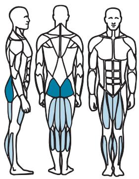
Muscles Trained During Low Incline

Primary -Gluteus Maximus, Hamstrings, Quadiceps,

Secondary - Adductors, Gastrocnemius, Soleus
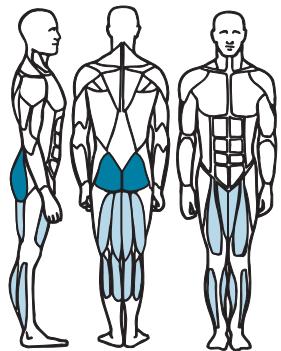
Muscles Trained During High Incline

Primary - Quadiceps, Gluteus Maximus

Secondary - Hamstrings, Adductors, Gastrocnemius, Soleus
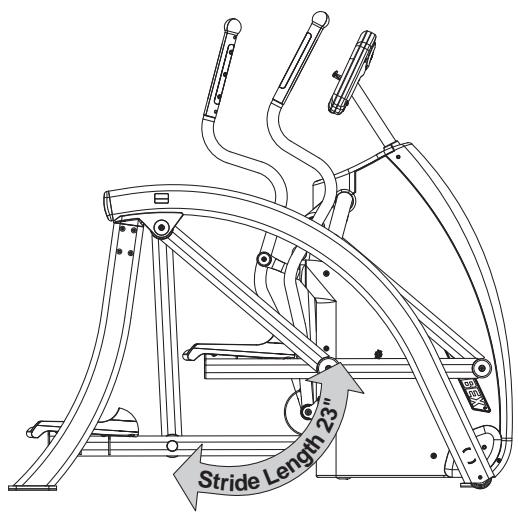
Figure 3
Speed Interval 1
Program Overview
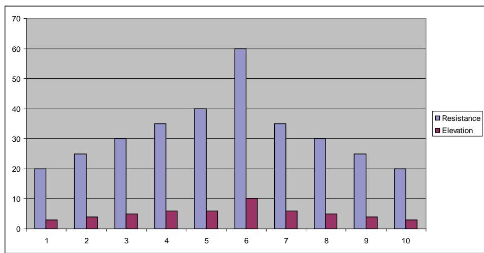
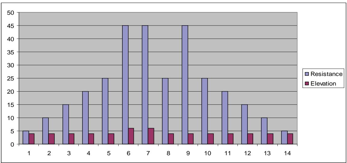
This program is designed to introduce the user to some higher intensity training. The program uses a fixed incline with resistance using a repeating 1:2 work to rest ratio. Each work segment lasts 30 seconds and each rest segment lasts 60 seconds. The resistance of the rest segments is 60 to 65% that of the work segments. Interval training is designed to tax both the aerobic and anaerobic energy systems. During the high intensity segments the anaerobic energy system is taxed. During the low intensity segments the aerobic energy system is used while the "oxygen debt" incurred during the high intensity segments is repaid. The repetition of the high intensity segments forces the body to adapt to the greater demands thereby helping the user to develop higher performance capabilities. See table below and Figure 4.
| Speed Interval 1 | Repeat | |||||||||
| Time | :30 | :30 | :30 | :30 | :30 | :30 | :30 | :30 | :30 | :30 |
| Distance | Refer to Notes | Refer to Notes | ||||||||
| Warm up | Program Segment | Cool Down | ||||||||
| Resistance | 1 | 2 | 3 | 4 | 1 | 2 | 3 | 1 | 2 | 3 |
| 10 | 35 | 45 | 55 | 65 | 70 | 45 | 45 | 40 | 35 | 30 |
| 9 | 35 | 40 | 50 | 60 | 65 | 40 | 40 | 35 | 30 | 25 |
| 8 | 30 | 40 | 50 | 55 | 60 | 35 | 35 | 30 | 25 | 20 |
| 7 | 30 | 35 | 45 | 50 | 55 | 30 | 30 | 30 | 25 | 20 |
| 6 | 25 | 35 | 40 | 45 | 50 | 30 | 30 | 30 | 25 | 20 |
| 5 | 25 | 30 | 35 | 40 | 45 | 25 | 25 | 25 | 20 | 15 |
| 4 | 20 | 25 | 30 | 35 | 40 | 25 | 25 | 25 | 20 | 15 |
| 3 | 20 | 25 | 30 | 30 | 35 | 20 | 20 | 20 | 15 | 10 |
| 2 | 15 | 20 | 25 | 30 | 30 | 20 | 20 | 20 | 15 | 10 |
| 1 | 10 | 15 | 20 | 20 | 25 | 15 | 15 | 15 | 15 | 10 |
| Elevation | Warm up | Program Segment | Cool Down | |||||||
| 1 | 2 | 3 | 4 | 1 | 2 | 3 | 1 | 2 | 3 | |
| 10 | 2 | 2 | 3 | 4 | 5 | 5 | 5 | 4 | 3 | 2 |
| 9 | 2 | 2 | 3 | 4 | 5 | 5 | 5 | 4 | 3 | 2 |
| 8 | 2 | 2 | 3 | 3 | 4 | 4 | 4 | 3 | 3 | 2 |
| 7 | 2 | 2 | 3 | 3 | 4 | 4 | 4 | 3 | 3 | 2 |
| 6 | 2 | 2 | 3 | 3 | 4 | 4 | 4 | 3 | 3 | 2 |
| 5 | 2 | 2 | 2 | 3 | 3 | 3 | 3 | 3 | 2 | 2 |
| 4 | 2 | 2 | 2 | 2 | 3 | 3 | 3 | 2 | 2 | 2 |
| 3 | 2 | 2 | 2 | 2 | 3 | 3 | 3 | 2 | 2 | 2 |
| 2 | 2 | 2 | 2 | 2 | 2 | 2 | 2 | 2 | 2 | 2 |
| 1 | 2 | 2 | 2 | 2 | 2 | 2 | 2 | 2 | 2 | 2 |
| Shown as a 10 minute program | ||||||||||
| Time may be increased in 1 minute blocks added to core program | ||||||||||
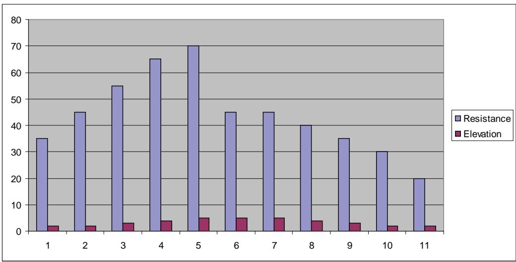
Speed Interval 1
Figure 4
Speed Interval 2
Program Overview
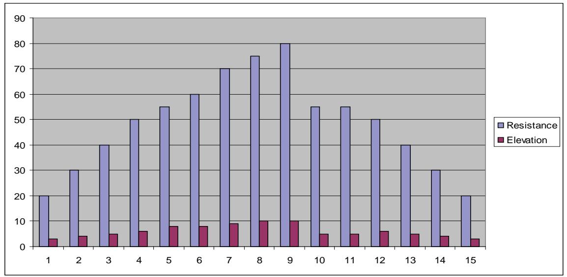
This program is designed for those who desire a higher intensity training interval training program. The program uses a fixed incline with resistance using a repeating 1:1 work to rest ratio. Each work segment lasts 60 seconds and each rest segment lasts 60 seconds. The resistance of the rest segments is approximately 55 to 65% that of the work segments. Interval training is designed to tax both the aerobic and anaerobic energy systems. During the high intensity segments the anaerobic energy system is taxed. During the low intensity segments the aerobic energy system is used while the "oxygen debt" incurred during the high intensity segments is repaid. In Interval 2 the extended work segment creates a greater "oxygen debt" than Interval 1 putting greater demand on both energy system and the repayment of the "oxygen debt" forcing even greater adaptation to the imposed demands. See table below and Figure 5.
| Interval 2 | Repeat | |||||||||
| Time | :30 | :30 | :30 | :30 | :30 | :30 | :30 | :30 | :30 | :30 |
| Distance | Refer to Notes | Program Segment | Refer to Notes | |||||||
| Warm up | Cool Down | |||||||||
| Resistance | 1 | 2 | 3 | 4 | 1 | 2 | 1 | 2 | 3 | 4 |
| 10 | 20 | 30 | 35 | 40 | 80 | 50 | 40 | 35 | 30 | 20 |
| 9 | 15 | 25 | 30 | 35 | 75 | 50 | 35 | 30 | 25 | 15 |
| 8 | 15 | 20 | 25 | 30 | 75 | 45 | 30 | 25 | 20 | 15 |
| 7 | 10 | 20 | 25 | 30 | 70 | 45 | 30 | 25 | 20 | 10 |
| 6 | 10 | 20 | 25 | 30 | 70 | 40 | 30 | 25 | 20 | 10 |
| 5 | 10 | 15 | 20 | 25 | 65 | 40 | 25 | 20 | 15 | 10 |
| 4 | 15 | 20 | 20 | 25 | 65 | 35 | 25 | 20 | 20 | 15 |
| 3 | 10 | 10 | 15 | 20 | 60 | 35 | 20 | 15 | 10 | 10 |
| 2 | 5 | 10 | 15 | 20 | 60 | 30 | 20 | 15 | 10 | 5 |
| 1 | 5 | 10 | 15 | 15 | 55 | 30 | 15 | 15 | 10 | 5 |
| Elevation | Warm up | Program Segment | Cool Down | |||||||
| 1 | 2 | 3 | 4 | 1 | 2 | 1 | 2 | 3 | 4 | |
| 10 | 2 | 2 | 3 | 4 | 5 | 5 | 4 | 3 | 2 | 2 |
| 9 | 2 | 2 | 3 | 4 | 5 | 5 | 4 | 3 | 2 | 2 |
| 8 | 2 | 2 | 3 | 3 | 4 | 4 | 3 | 3 | 2 | 2 |
| 7 | 2 | 2 | 3 | 3 | 4 | 4 | 3 | 3 | 2 | 2 |
| 6 | 2 | 2 | 3 | 3 | 4 | 4 | 3 | 3 | 2 | 2 |
| 5 | 2 | 2 | 2 | 3 | 3 | 3 | 3 | 2 | 2 | 2 |
| 4 | 2 | 2 | 2 | 2 | 3 | 3 | 2 | 2 | 2 | 2 |
| 3 | 2 | 2 | 2 | 2 | 3 | 3 | 2 | 2 | 2 | 2 |
| 2 | 2 | 2 | 2 | 2 | 2 | 2 | 2 | 2 | 2 | 2 |
| 1 | 2 | 2 | 2 | 2 | 2 | 2 | 2 | 2 | 2 | 2 |
| Time may be increased in 1 minute blacks added to core program | ||||||||||
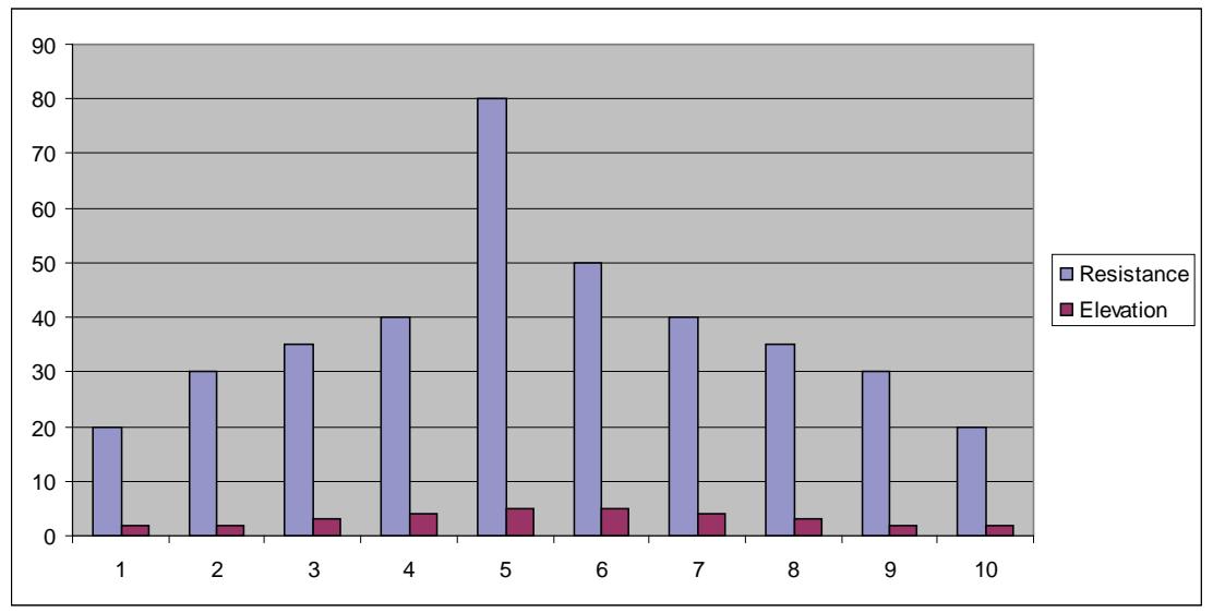
Speed Interval 2
Figure 5
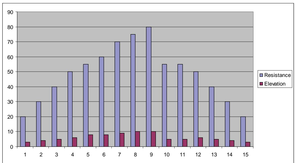
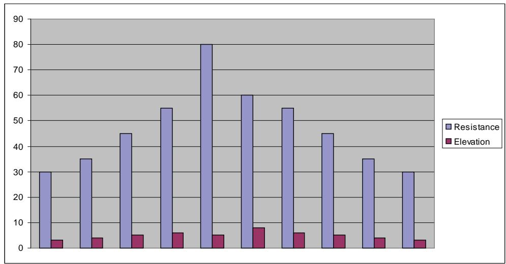
Hills Interval
Program Overview
The Hills program is designed to give the user the experience of hiking in a hilly terrain. This program uses intervals of moderate resistance and incline to simulate relatively flat areas and intervals of substantially greater incline and resistance to simulate steeper grades. Likewise the two-minute work segments are intended to tax the users capabilities, while the two-minute rest allows for recuperation and allows for repeated work segments. See table on next page and Figure 6.
| Hills Interval | ||||||||||
| Time | :30 | :30 | :30 | :30 | :30 | :30 | :30 | :30 | :30 | :30 |
| Distance | Program Segments | |||||||||
| Warm up | Cool Down | |||||||||
| Resistance | 1 | 2 | 3 | 4 | 1 | 2 | 1 | 2 | 3 | 4 |
| 10 | 20 | 25 | 30 | 35 | 40 | 60 | 35 | 30 | 25 | 20 |
| 9 | 20 | 25 | 30 | 35 | 40 | 50 | 35 | 30 | 25 | 20 |
| 8 | 15 | 20 | 25 | 30 | 35 | 45 | 30 | 25 | 20 | 15 |
| 7 | 15 | 20 | 25 | 30 | 35 | 40 | 30 | 25 | 20 | 15 |
| 6 | 15 | 15 | 20 | 25 | 30 | 35 | 25 | 20 | 15 | 15 |
| 5 | 15 | 15 | 20 | 25 | 30 | 25 | 25 | 20 | 15 | 15 |
| 4 | 10 | 10 | 15 | 20 | 25 | 30 | 20 | 15 | 10 | 10 |
| 3 | 10 | 10 | 15 | 20 | 25 | 25 | 20 | 15 | 10 | 10 |
| 2 | 10 | 10 | 10 | 15 | 20 | 20 | 15 | 10 | 10 | 10 |
| 1 | 10 | 10 | 10 | 10 | 15 | 15 | 10 | 10 | 10 | 10 |
| Elevation | Warm up | Program Segments | Cool Down | |||||||
| 1 | 2 | 3 | 4 | 1 | 2 | 1 | 2 | 3 | 4 | |
| 10 | 3 | 4 | 5 | 6 | 6 | 10 | 6 | 5 | 4 | 3 |
| 9 | 3 | 3 | 4 | 5 | 5 | 10 | 5 | 4 | 3 | 3 |
| 8 | 3 | 3 | 4 | 5 | 5 | 9 | 5 | 4 | 3 | 3 |
| 7 | 3 | 3 | 3 | 4 | 4 | 9 | 4 | 3 | 3 | 3 |
| 6 | 3 | 3 | 3 | 4 | 4 | 8 | 4 | 3 | 3 | 3 |
| 5 | 3 | 3 | 3 | 3 | 3 | 8 | 3 | 3 | 3 | 3 |
| 4 | 3 | 3 | 3 | 3 | 3 | 7 | 3 | 3 | 3 | 3 |
| 3 | 2 | 2 | 3 | 3 | 3 | 7 | 3 | 3 | 2 | 2 |
| 2 | 2 | 2 | 3 | 3 | 3 | 6 | 3 | 3 | 2 | 2 |
| 1 | 2 | 2 | 3 | 3 | 3 | 6 | 3 | 3 | 2 | 2 |
| Shown as a 10 minute program | ||||||||||
| Time may be increased in 1 minute blocks added to core program | ||||||||||
Hills Interval
Figure 6
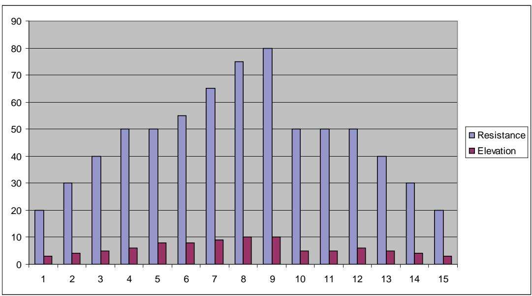
Valleys
Program Overview
The Valleys program provides a contrasting mix of incline and resistance. The program uses a five minute core during which the resistance is increased and the incline is reduced in the first three minutes followed by and a reduction in resistance and an increase in incline until the valley repeats itself. This program is designed specifically to contrast the Ramps and Hills programs for added training variety. See table below and Figure 7.
| Valleys | ||||||||||||
| Time | :30 | :30 | :30 | :30 | 1:00 | 1:00 | 1:00 | 1:00 | 1:00 | :30 | :30 | :30 |
| Distance | Refer to Notes | |||||||||||
| Warm up | Program Segment | Cool Down | ||||||||||
| Resistance | 1 | 2 | 3 | 4 | 1 | 2 | 3 | 4 | 5 | 1 | 2 | 3 |
| 10 | 20 | 25 | 30 | 40 | 50 | 65 | 80 | 65 | 50 | 40 | 30 | 25 |
| 9 | 20 | 25 | 30 | 35 | 50 | 60 | 75 | 60 | 50 | 35 | 30 | 25 |
| 8 | 20 | 25 | 30 | 35 | 45 | 55 | 70 | 55 | 45 | 35 | 30 | 25 |
| 7 | 15 | 20 | 25 | 35 | 45 | 50 | 65 | 50 | 45 | 35 | 25 | 15 |
| 6 | 15 | 20 | 25 | 30 | 40 | 45 | 60 | 45 | 40 | 30 | 25 | 15 |
| 5 | 10 | 15 | 20 | 20 | 40 | 40 | 55 | 40 | 40 | 20 | 20 | 15 |
| 4 | 10 | 10 | 15 | 15 | 30 | 35 | 50 | 35 | 30 | 15 | 15 | 10 |
| 3 | 5 | 10 | 10 | 15 | 30 | 30 | 45 | 30 | 30 | 15 | 10 | 5 |
| 2 | 5 | 5 | 10 | 10 | 20 | 20 | 40 | 20 | 20 | 10 | 10 | 5 |
| 1 | 5 | 5 | 10 | 10 | 15 | 20 | 35 | 20 | 15 | 10 | 10 | 5 |
| Elevation | Warm up | Program Segment | Cool Down | |||||||||
| 1 | 2 | 3 | 4 | 1 | 2 | 3 | 4 | 5 | 1 | 2 | 3 | |
| 10 | 3 | 4 | 5 | 5 | 10 | 5 | 1 | 5 | 10 | 5 | 5 | 4 |
| 9 | 3 | 4 | 5 | 5 | 10 | 4 | 1 | 4 | 10 | 5 | 5 | 4 |
| 8 | 3 | 4 | 4 | 4 | 9 | 4 | 1 | 4 | 9 | 4 | 4 | 3 |
| 7 | 3 | 3 | 4 | 4 | 9 | 4 | 1 | 4 | 9 | 4 | 4 | 3 |
| 6 | 3 | 3 | 4 | 4 | 8 | 3 | 1 | 3 | 8 | 4 | 4 | 3 |
| 5 | 3 | 3 | 4 | 4 | 7 | 3 | 1 | 3 | 7 | 4 | 4 | 3 |
| 4 | 3 | 3 | 4 | 4 | 6 | 3 | 1 | 3 | 6 | 4 | 4 | 3 |
| 3 | 3 | 3 | 4 | 4 | 5 | 2 | 1 | 2 | 5 | 4 | 4 | 3 |
| 2 | 3 | 3 | 4 | 4 | 4 | 2 | 1 | 2 | 4 | 4 | 4 | 3 |
| 1 | 3 | 3 | 4 | 4 | 3 | 2 | 1 | 2 | 3 | 4 | 4 | 3 |
Valleys
Figure 7
Ramps
Program Overview
The Ramps program is similar to the Hills program but uses a more linear ramp to both incline and resistance from segment to segment. Ramps is comprised of a 3 12 minute core where the incline and resistance both increase over the first 2 12 minutes followed by a one minute reduction of both incline and resistance. The
reduction in incline and resistance is designed to provide a working rest period before the ramp is repeated. See table below and Figure 8.
| Ramps | |||||||||||||
| Time | :30 | :30 | :30 | :30 | :30 | :30 | :30 | :30 | :30 | :30 | :30 | ||
| Distance | Refer to Notes | Refer to Notes | Refer to Notes | ||||||||||
| Warm up | Program Segment | Cool Down | |||||||||||
| Resistance | 1 | 2 | 3 | 4 | 1 | 2 | 3 | 4 | 5 | 6 | 7 | 1 | 2 |
| 10 | 20 | 30 | 40 | 50 | 55 | 60 | 70 | 75 | 80 | 55 | 55 | 50 | 40 |
| 9 | 20 | 30 | 40 | 45 | 55 | 65 | 65 | 70 | 75 | 55 | 55 | 45 | 40 |
| 8 | 20 | 30 | 35 | 40 | 50 | 60 | 60 | 65 | 70 | 50 | 50 | 40 | 35 |
| 7 | 15 | 25 | 35 | 35 | 45 | 55 | 55 | 60 | 65 | 45 | 45 | 35 | 35 |
| 6 | 15 | 25 | 30 | 35 | 40 | 50 | 50 | 55 | 60 | 40 | 40 | 35 | 30 |
| 5 | 15 | 25 | 30 | 30 | 35 | 45 | 45 | 50 | 55 | 35 | 35 | 30 | 25 |
| 4 | 10 | 20 | 25 | 30 | 30 | 40 | 40 | 45 | 50 | 30 | 30 | 30 | 25 |
| 3 | 10 | 20 | 25 | 25 | 25 | 35 | 35 | 40 | 45 | 25 | 25 | 25 | 20 |
| 2 | 10 | 15 | 20 | 20 | 20 | 30 | 30 | 35 | 40 | 20 | 20 | 20 | 15 |
| 1 | 10 | 10 | 15 | 15 | 15 | 20 | 25 | 30 | 35 | 15 | 15 | 15 | 10 |
| Elevation | Warm up | Program Segment | Cool Down | ||||||||||
| 1 | 2 | 3 | 4 | 1 | 2 | 3 | 1 | 2 | 5 | 5 | 1 | 2 | |
| 10 | 3 | 4 | 5 | 6 | 8 | 8 | 9 | 10 | 10 | 5 | 5 | 6 | 5 |
| 9 | 3 | 3 | 4 | 5 | 7 | 8 | 8 | 9 | 10 | 5 | 5 | 5 | 4 |
| 8 | 3 | 3 | 4 | 4 | 7 | 7 | 8 | 9 | 9 | 5 | 5 | 4 | 4 |
| 7 | 3 | 3 | 4 | 4 | 6 | 7 | 7 | 8 | 9 | 5 | 5 | 4 | 4 |
| 6 | 3 | 3 | 3 | 4 | 6 | 6 | 7 | 8 | 8 | 5 | 5 | 4 | 3 |
| 5 | 3 | 3 | 3 | 3 | 5 | 6 | 6 | 7 | 8 | 5 | 5 | 3 | 3 |
| 4 | 2 | 2 | 2 | 3 | 5 | 5 | 6 | 7 | 7 | 5 | 5 | 3 | 2 |
| 3 | 2 | 2 | 2 | 3 | 4 | 5 | 5 | 6 | 7 | 5 | 5 | 3 | 2 |
| 2 | 2 | 2 | 2 | 2 | 4 | 4 | 5 | 6 | 6 | 5 | 5 | 2 | 2 |
| 1 | 2 | 2 | 2 | 2 | 3 | 4 | 4 | 5 | 6 | 5 | 5 | 2 | 2 |
| Shown as a 10 minute program | |||||||||||||
| Time may be increased in 1 minute blocks added to core program | |||||||||||||
Ramps
Figure 8
Hills
Program Overview
The Hills program uses a 3 12 minute core where the incline and resistance both increase over the first 2 12 minutes followed by a one minute reduction of both incline and resistance. The reduction in incline and resistance is designed to simulate reaching the top a hill and level ground. The climb up the hill is then repeated. See table below and Figure 9.
| Hills | |||||||||||||||
| Time | :30 | :30 | :30 | :30 | :30 | :30 | :30 | :30 | :30 | :30 | :30 | :30 | :30 | :30 | |
| Distance | Refer to Notes | Program Segments | Refer to Notes | Refer to Notes | |||||||||||
| Warm up | Cool Down | Cool Down | |||||||||||||
| Resistance | 1 | 2 | 3 | 4 | 1 | 2 | 3 | 1 | 2 | 3 | 4 | 1 | 2 | 3 | 4 |
| 10 | 20 | 30 | 40 | 50 | 50 | 55 | 65 | 75 | 80 | 50 | 50 | 50 | 40 | 30 | 20 |
| 9 | 20 | 30 | 40 | 45 | 45 | 50 | 60 | 70 | 75 | 45 | 45 | 45 | 40 | 30 | 20 |
| 8 | 20 | 30 | 35 | 40 | 40 | 45 | 55 | 65 | 75 | 40 | 40 | 40 | 35 | 30 | 20 |
| 7 | 15 | 25 | 35 | 35 | 35 | 45 | 50 | 60 | 70 | 35 | 35 | 35 | 35 | 25 | 15 |
| 6 | 15 | 25 | 30 | 35 | 35 | 40 | 50 | 55 | 65 | 35 | 35 | 35 | 30 | 25 | 15 |
| 5 | 15 | 25 | 30 | 30 | 30 | 35 | 45 | 50 | 60 | 30 | 30 | 30 | 30 | 25 | 15 |
| 4 | 10 | 20 | 25 | 30 | 25 | 30 | 40 | 50 | 55 | 25 | 25 | 30 | 25 | 20 | 10 |
| 3 | 10 | 20 | 25 | 25 | 20 | 30 | 40 | 45 | 50 | 20 | 20 | 25 | 25 | 20 | 10 |
| 2 | 10 | 15 | 20 | 25 | 20 | 25 | 35 | 40 | 45 | 20 | 20 | 25 | 20 | 15 | 10 |
| 1 | 10 | 10 | 15 | 15 | 30 | 20 | 30 | 35 | 40 | 20 | 20 | 15 | 15 | 10 | 10 |
| Elevation | Warm up | Program Segments | Cool Down | Cool Down | |||||||||||
| 1 | 2 | 3 | 4 | 1 | 2 | 3 | 1 | 2 | 3 | 4 | 1 | 2 | 3 | 4 | |
| 10 | 3 | 4 | 5 | 6 | 8 | 8 | 9 | 10 | 10 | 5 | 5 | 6 | 5 | 4 | 3 |
| 9 | 3 | 3 | 4 | 5 | 7 | 8 | 8 | 9 | 10 | 5 | 5 | 5 | 4 | 3 | 3 |
| 8 | 3 | 3 | 4 | 4 | 7 | 7 | 8 | 9 | 9 | 5 | 5 | 4 | 4 | 3 | 3 |
| 7 | 3 | 3 | 4 | 4 | 6 | 7 | 7 | 8 | 9 | 5 | 5 | 4 | 4 | 3 | 3 |
| 6 | 3 | 3 | 3 | 4 | 6 | 6 | 7 | 8 | 8 | 5 | 5 | 4 | 3 | 3 | 3 |
| 5 | 3 | 3 | 3 | 3 | 5 | 6 | 6 | 7 | 8 | 5 | 5 | 3 | 3 | 3 | 3 |
| 4 | 2 | 2 | 2 | 3 | 5 | 5 | 6 | 7 | 7 | 5 | 5 | 3 | 2 | 2 | 2 |
| 3 | 2 | 2 | 2 | 3 | 4 | 5 | 5 | 6 | 7 | 5 | 5 | 3 | 2 | 2 | 2 |
| 2 | 2 | 2 | 2 | 2 | 4 | 4 | 5 | 6 | 6 | 5 | 5 | 2 | 2 | 2 | 2 |
| 1 | 2 | 2 | 2 | 2 | 3 | 4 | 4 | 5 | 6 | 5 | 4 | 2 | 2 | 2 | 2 |
| Shown as a 10 minute program | |||||||||||||||
| Time may be increased in 1 minute blocks added to core program | |||||||||||||||
Hills
Figure 9
Weight Loss
Program Overview
The Weight Loss program is designed for low to medium intensity training that the user can sustain for an extended period of time. It builds from a low intensity baseline to include segments of higher incline and resistance as well as segments that use higher resistance with the baseline incline. The constant variety porvides for periods of higher expenditure and training effect without the introduction of undue fatigue allowing the user to perform for longer periods of time. See table below and Figure 10.
| Weight Loss | ||||||||||||||
| Time | :30 | :30 | :30 | :30 | 1:00 | 1:00 | 1:00 | 1:00 | 1:00 | 1:00 | :30 | :30 | :30 | |
| Distance | Refer to Notes | |||||||||||||
| Warm up | Program Segments | Cool Down | ||||||||||||
| Resistance | 1 | 2 | 3 | 4 | 1 | 2 | 3 | 4 | 5 | 6 | 1 | 2 | 3 | 4 |
| 10 | 5 | 10 | 15 | 20 | 25 | 45 | 45 | 25 | 45 | 25 | 20 | 15 | 10 | 5 |
| 9 | 5 | 10 | 15 | 20 | 25 | 40 | 40 | 25 | 40 | 25 | 20 | 15 | 10 | 5 |
| 8 | 5 | 10 | 15 | 20 | 25 | 35 | 35 | 25 | 35 | 25 | 20 | 15 | 10 | 5 |
| 7 | 5 | 5 | 10 | 15 | 25 | 40 | 40 | 25 | 40 | 25 | 15 | 10 | 5 | 5 |
| 6 | 5 | 5 | 10 | 15 | 25 | 35 | 35 | 25 | 35 | 25 | 15 | 10 | 5 | 5 |
| 5 | 5 | 5 | 10 | 15 | 25 | 30 | 30 | 25 | 30 | 25 | 15 | 10 | 5 | 5 |
| 4 | 5 | 5 | 5 | 10 | 15 | 25 | 25 | 15 | 25 | 15 | 10 | 5 | 10 | 8 |
| 3 | 5 | 5 | 5 | 10 | 15 | 20 | 20 | 15 | 20 | 15 | 10 | 5 | 10 | 8 |
| 2 | 5 | 5 | 5 | 5 | 5 | 15 | 15 | 5 | 15 | 5 | 5 | 4 | 3 | 3 |
| 1 | 5 | 5 | 5 | 5 | 5 | 10 | 10 | 5 | 10 | 5 | 5 | 4 | 3 | 3 |
| Elevation | Warm up | Program Segments | Cool Down | |||||||||||
| 1 | 2 | 3 | 4 | 1 | 2 | 3 | 4 | 5 | 6 | 1 | 2 | 3 | 4 | |
| 10 | 4 | 4 | 4 | 4 | 4 | 6 | 6 | 4 | 4 | 4 | 4 | 4 | 4 | 4 |
| 9 | 4 | 4 | 4 | 4 | 4 | 6 | 6 | 4 | 4 | 4 | 4 | 4 | 4 | 4 |
| 8 | 3 | 3 | 3 | 3 | 3 | 6 | 6 | 3 | 3 | 3 | 3 | 3 | 3 | 3 |
| 7 | 3 | 3 | 3 | 3 | 3 | 4 | 4 | 3 | 3 | 3 | 3 | 3 | 3 | 3 |
| 6 | 3 | 3 | 3 | 3 | 3 | 4 | 4 | 3 | 3 | 3 | 3 | 3 | 3 | 3 |
| 5 | 3 | 3 | 3 | 3 | 3 | 4 | 4 | 3 | 3 | 3 | 3 | 3 | 3 | 3 |
| 4 | 2 | 2 | 2 | 2 | 2 | 3 | 3 | 2 | 2 | 2 | 2 | 2 | 2 | 2 |
| 3 | 2 | 2 | 2 | 2 | 2 | 3 | 3 | 2 | 2 | 2 | 2 | 2 | 2 | 2 |
| 2 | 2 | 2 | 2 | 2 | 2 | 3 | 3 | 2 | 2 | 2 | 2 | 2 | 2 | 2 |
| 1 | 2 | 2 | 2 | 2 | 2 | 3 | 3 | 2 | 2 | 2 | 2 | 2 | 2 | 2 |
Weight Loss
Figure 10
Cardio
Program Overview
The Cardio program is designed for experienced users that desire a high intensity cardiovascular training experience. The two-minute work interval with high resistance ensures that the aerobic energy system is completely taxes, while the subsequent two-minute rest interval allows for recovery enabling a repeat at the higher work rate. Additionally, a higher incline level is used during the recovery interval to discourage blood pooling, ensuring more complete recovery. See table below and Figure 11.
| Cardio | |||||||||
| Time | :30 | :30 | :30 | :30 | :30 | :30 | :30 | :30 | :30 |
| Distance | Refer to Notes | Program Segments | Refer to Notes | ||||||
| Warm up | Cool Down | ||||||||
| Resistance | 1 | 2 | 3 | 4 | 1 | 2 | 1 | 2 | 3 |
| 10 | 30 | 35 | 45 | 55 | 80 | 60 | 55 | 45 | 35 |
| 9 | 25 | 35 | 45 | 55 | 75 | 55 | 55 | 45 | 35 |
| 8 | 25 | 30 | 40 | 45 | 70 | 50 | 45 | 40 | 30 |
| 7 | 20 | 25 | 35 | 40 | 65 | 45 | 40 | 35 | 25 |
| 6 | 15 | 20 | 30 | 35 | 60 | 40 | 35 | 30 | 20 |
| 5 | 15 | 20 | 25 | 30 | 55 | 35 | 30 | 25 | 20 |
| 4 | 10 | 15 | 20 | 25 | 50 | 30 | 25 | 20 | 15 |
| 3 | 5 | 10 | 15 | 20 | 45 | 30 | 20 | 15 | 10 |
| 2 | 0 | 5 | 10 | 15 | 40 | 25 | 15 | 10 | 5 |
| 1 | 0 | 0 | 5 | 10 | 35 | 20 | 10 | 5 | 0 |
| Warm up | Program Segments | Cool Down | |||||||
| Elevation | |||||||||
| 1 | 2 | 3 | 4 | 1 | 2 | 1 | 2 | 3 | |
| 10 | 3 | 4 | 5 | 6 | 5 | 8 | 6 | 5 | 4 |
| 9 | 3 | 3 | 4 | 5 | 5 | 8 | 5 | 4 | 3 |
| 8 | 3 | 3 | 4 | 4 | 5 | 7 | 4 | 4 | 3 |
| 7 | 3 | 3 | 4 | 4 | 4 | 7 | 4 | 4 | 3 |
| 6 | 3 | 3 | 3 | 4 | 4 | 6 | 4 | 3 | 3 |
| 5 | 3 | 3 | 3 | 3 | 4 | 6 | 3 | 3 | 3 |
| 4 | 2 | 2 | 2 | 3 | 3 | 5 | 3 | 2 | 2 |
| 3 | 2 | 2 | 2 | 3 | 3 | 5 | 3 | 2 | 2 |
| 2 | 2 | 2 | 2 | 2 | 2 | 4 | 2 | 2 | 2 |
| 1 | 2 | 2 | 2 | 2 | 2 | 4 | 2 | 2 | 2 |
| Shown as a 10 minute program | |||||||||
| Time may be increased in 1 minute blocks added to core program | |||||||||
Cardio
Figure 11
Cybex 425A Arc Owner's Manual
This page intentionally left blank.
4 - Preventive Maintenance

Warnings
All warnings and cautions listed in this chapter are as follows:

WARNING: All maintenance activities shall be performed by qualified personnel. Failure to do so could result in serious injury.

WARNING: To prevent electrical shock, be sure the unit is unplugged from the electrical outlet before performing any cleaning or maintenance procedures.

WARNING: Keep wet items away from inside parts of the unit. Electrical shock could occur even if the unit is unplugged. Do not touch components on the lower board. A charge can remain after unplugging the power cord.

WARNING: Disconnect the power cord before beginning this procedure. Keep wet items away from inside parts of the unit. Electrical shock could occur even if the unit is unplugged.

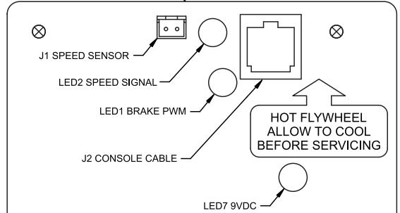
WARNING: The flywheel may be hot. Wait until it cools before servicing.
Regular Maintenance Activities

WARNING: All maintenance activities shall be performed by qualified personnel. Failure to do so could result in serious injury.
Preventive maintenance activities must be performed to maintain normal operation of your unit. Keeping a log of all maintenance actions will assist you in staying current with all preventive maintenance activities. See Service Schedule located at the end of this chapter.
NOTE: Worn or damaged components shall be replaced immediately or the unit removed from service until the repair is made.
NOTE: Cybex is not responsible for performing regular inspection and maintenance actions for your unit. Instruct all personnel in equipment inspection and maintenance actions and also in accident reporting/recording.
Cleaning Your Arc Trainer 425A

WARNING: To prevent electrical shock, be sure the unit is unplugged from the electrical outlet before performing any cleaning or maintenance procedures.
When cleaning your unit spray a mild cleaning agent, such as a water and dish soap solution, on a clean cloth first and then wipe the unit with the damp cloth.
NOTE: Do not spray cleaning solution directly on the unit. Direct spraying could cause damage to the electronics and may void the warranty.
After Each Use - Wipe up any liquid spills immediately. After each workout, use a cloth to wipe up any remaining perspiration from the handles and painted surfaces.
Be careful not to spill or get excessive moisture on the console and display overlays, as this might create an electrical hazard or cause failure of the electronics.
As Needed - Vacuum any dust or dirt that might accumulate under or around the unit. Cleaning this area should be done as often as indicated in the Service Schedule.

WARNING: Keep wet items away from inside parts of the unit. Electrical shock could occur even if the unit is unplugged. Do not touch components on the lower board. A charge can remain after unplugging the power cord.
To clean inside the unit, remove the four Phillips head screws securing the access cover in place. Use a vacuum attachment or hand vacuum to clean the exposed elevation assembly and remove dirt and debris off of internal components.
Use a dry cloth to wipe all exposed areas. Replace the access cover and secure it with the screws when finished.
Lift the rear of the unit and roll it back from its present position so as to vacuum the floor area underneath the unit. When finished, return the unit to its normal position.
Contact Heart Rate Grips - Contaminants, such as hand lotions, oils or body powder, may come off on the contact heart rate grips. These can reduce sensitivity and interfere with the heart rate signal. It is recommended that the user have clean hands when using the contact heart rate. Clean the grips using a cloth dampened with a cleaning solution containing alcohol. The grips are the only part of the unit you should use a cleaning solution containing alcohol.
Drive Belt Maintenance
There are two drive belts that may become loose, worn or cracked. See Figure 1.
Primary Belt - This is the wider of the two belts. It has grooves that keep it aligned on the large upper pulley. It is unlikely that the primary belt will become loose because it is a stretch-fit belt.
Secondary Belt - This is the narrower of the two belts. It has grooves that keep it aligned on the flywheel's drive pulley. It is unlikely that the secondary belt will become loose because it is a stretch-fit belt.
NOTE: If a belt has cracks or appears worn, it must be replaced immediately by a qualified service technician.
Tools Required
- Phillips head screwdriver
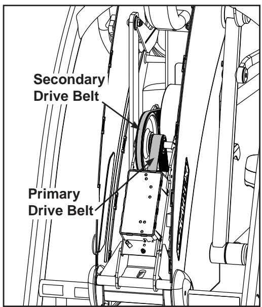
Figure 1

WARNING: Disconnect the power cord from the wall outlet before beginning this procedure. Keep wet items away from inside parts of the unit. Electrical shock could occur even if the unit is unplugged.
- Read and understand this Drive Belt Maintenance section thoroughly before proceeding to step 2.
- Disconnect the external power source.
A. Unplug the power cord from the power outlet.
- Remove the access cover.
A. Using a Philips screwdriver, remove the four screws securing the access cover.
B. Remove the access cover.

WARNING: the flywheel may be hot. Wait until it cools before servicing.
- Check the condition of each belt.
A. Roll each belt by to examine it condition. If a belt has cracks or appears worn, it must be replaced immediately by a qualified service technician.
- Attach the access cover.
A. Using a Philips head screwdriver, tighten the screws first (removed in step 3A). NOTE: Do not over tighten screws.
- Test unit for proper operation.
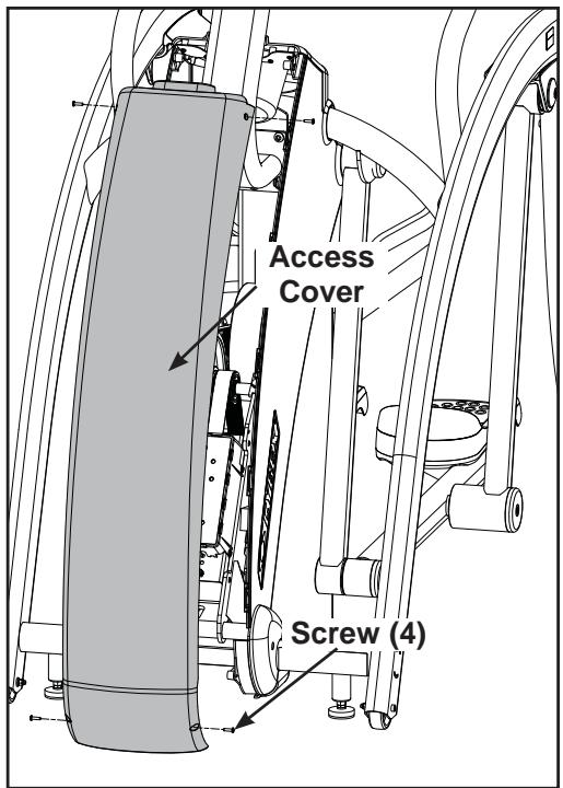
Figure 2
Lubrication
The Arc Trainer 425A is designed with no-maintenance parts. Although there are grease fittings on the pillow blocks, re-lubrication of the bearings is not required.
Elevation Motor Lubrication - In time the elevation motor pivot points may develop a squeak. If a squeak is present, the unit will need to be serviced by a qualified service technician.
Environment
Static Electricity - Depending upon where you live, you may experience dry air, causing a common experience of static electricity. This may be especially true in the winter time. You may notice a static build-up just by walking across a carpet and then touching a metal object. The same can hold true while working out on your unit. You may experience a shock due to the build-up of static electricity on your body and the discharge path of the unit. If you experience this type of situation, you may want to increase the humidity to a comfortable level through the use of a humidifier.
Humidity - The unit is designed to function normally in an environment with a relative humidity range of 30% to 75% .
NOTE: Do not install or use the unit in an area of high humidity, such as in the vicinity of a steam room, sauna, indoor pool or outdoors. Exposure to extensive water vapor, chlorine and/or bromine could adversely affect the electronics as well as other parts of the machine.
Temperature - The unit is designed to function normally in an environment with an ambient temperature range of 50^ ( 10^ ) to 104^ ( 40^ ) degrees.
Storage
Humidity - The unit can be shipped and stored in an environment with a relative humidity range of 10% to 90% .
NOTE: Do not store the unit in an area of high humidity, such as in the vicinity of a steam room, sauna, indoor pool or outdoors. Exposure to extensive water vapor, chlorine and/or bromine could adversely affect the electronics as well as other parts of the machine.
Temperature - The unit can be shipped and stored in an environment with an ambient temperature range of 32^ ( 0^ ) and 140^ ( 60^ ) degrees.
5 - Setup and Assembly

Warnings/Cautions
All warnings and cautions listed in this chapter are as follows:

WARNING: Use extreme caution when assembling the unit. Failure to do so could result in injury.

WARNING: A minimum of two people are required to lift, move and assemble this unit. Always use proper lifting methods when moving heavy items.

WARNING: Be sure that all electrical requirements are met as indicated in the specifications at the front of the manual and at the beginning of this chapter prior to proceeding.

WARNING: Wait until all moving parts come to a complete stop before dismounting.

CAUTION: A minimum of two people are required to assemble this unit.
Choosing and Preparing a Site
Before assembling the unit you must select a suitable site and have the proper electrical outlet power available for optimum operation and safety. See the Electrical Power Requirements section (located on the next page) for direction in locating your voltage requirements.
The area you select for the unit should be well lit and well ventilated. Locate the unit on a structurally sound and level surface. Allow enough clearance for safe access and passage during use of the unit. Allow a minimum of 5^ (13 cm) behind the unit for the elevation to rise. If the unit is to be located above the first floor, place it near or above major support beams. To protect the carpeting, place a 3/4" (1.9 cm) thick wood base under the unit. Be sure to use the rubber foot covers shown on page 5-9.
Humidity - The unit is designed to function normally in an environment with a relative humidity range of 30% to 75% .
NOTE: Do not install or use the unit in an area of high humidity, such as in the vicinity of a steam room, sauna, indoor pool or outdoors. Exposure to extensive water vapor, chlorine and/or bromine could adversely affect the electronics as well as other parts of the machine.
Temperature - The unit is designed to function normally in an environment with an ambient temperature range of 50^ ( 10^ ) to 104^ ( 40^ ) degrees.
See Chapter 4 for information regarding storage of the unit.
Electrical Power Requirements
The power requirements for the unit are a grounded circuit rated for one of the following: 115VAC^±5% 50 / 60~Hz and 15 amps; or 230VAC^±10% 50 / 60~Hz . Contact your electrician to ensure the power supply complies with local building codes. NOTE: Do not use a ground plug adapter to adapt the 3-prong power cord plug to a non-grounded electrical outlet.
Assembling the Arc Trainer 425A

WARNING: Use extreme caution when assembling the unit. Failure to do so could result in injury.

CAUTION: A minimum of two people are required to assemble this unit.
Tools Required
- Phillips head screwdriver
- 7/32" Allen wrench (2 supplied)
- 5/32" Allen wrench (supplied)
9/16" Open-end wrench
NOTE: The words "left" and "right" denote the user's orientation.
- Read and understand all instructions thoroughly before assembling the unit.
NOTE: Each step number in the assembly instructions tells you what you will be doing. The lettered steps following each step number describe the procedure required. Do not continue with step 2 until you have carefully read all of the assembly instructions.
- Verify you have received the correct package.
A. Read the sticker on the outside of the box and verify that the model number and voltage are what you ordered.
- Unpack and verify the contents of the boxes.
A. Lift up and remove the cardboard sleeve that surrounds the unit.
B. Verify that you have the color that you ordered by looking at the paint.
C. Verify that you have the correct voltage by reading the voltage sticker near the power inlet.
D. Check to be sure that the following items are present. Check off ( l each item as you find it. See Figure 1. If any of the parts are missing contact Cybex Customer Service.
| Item | Qty | Part Number | Description |
| ☐ 1 | 1 | Varies | Base with covers attached |
| ☐ 2 | 1 | Varies | Console assembly (in box) |
| ☐ 3 | 2 | 11090-405 | Foot pad (in box) |
| ☐ 4 | 1 | NA | Hardware pack (in box) |
| ☐ 5 | 1 | 5425A-4 | Owner's Manual (in box) |
| ☐ 6 | 1 | 425A-396 | Assembly poster |
| ☐ 7 | 1 | 425A-395 | Warranty sheet |
| ☐ 8 | 1 | 425A-459 | Cover, Front |
| ☐ 9 | 1 | 425A-462 | Cover, Side, Upper Left |
| ☐ 10 | 1 | 425A-460 | Cover, Side, Upper Right |
| ☐ 11 | 1 | 425A-458 | Cover, Top |
| ☐ 12 | 1 | 425A-206 | Console Support Bracket |
| ☐ 13 | 1 | 425A-208 | Handle, Left |
| ☐ 14 | 1 | 425A-209 | Handle, Right |
| NA means Not Applicable | |||
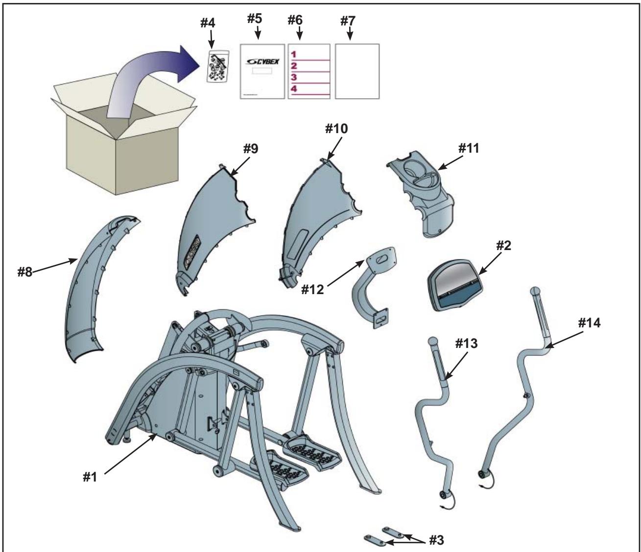
Figure 1
E. Check off (√) each item in the hardware pack as you find it. See Figure 2 and 3.
| Item | Qty | Part Number | Description |
| □15 | 1 | 425A-449 | Pivot Shaft |
| □16 | 1 | YA000221 | Threadlocker |
| □17 | 7 | HT542514 | PH HD Phil SC #8 X .625 BLK |
| □18 | 2 | JC700412 | BHSCS .375-16 x .50 |
| □19 | 3 | HC700415 | BHSCS .375-16 x .75 |
| □20 | 2 | HC620414 | BHSCS .250-20 x .625 |
| □21 | 4 | HX620420 | BHSCS .250-20 x 1.250 |
| □22 | 4 | HS307400 | Lock Washer |
| □23 | 2 | HS347600 | Washer |
| □24 | 2 | 425A-482 | End Cap |
| □25 | 2 | HS307601 | Washer |
| □26 | 1 | BK030205 | 5/32" Allen wrench |
| □27 | 2 | BK030204 | 7/32" Allen wrench |
| □28 | 2 | 600A-311 | Spacer |
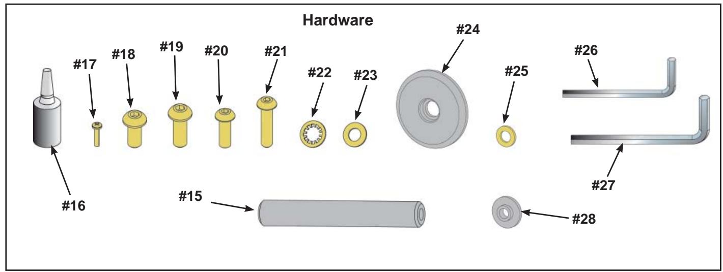
Figure 2
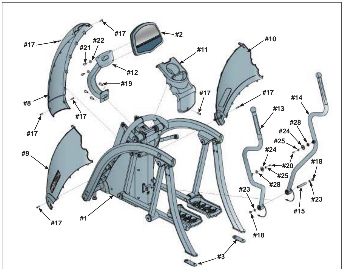
Figure 3

CAUTION: A minimum of two people are required to lift, move and assemble the unit. Always use proper lifting methods when moving heavy items.
4. Lift and move the unit
A. Carefully remove lag bolts and shipping supports. NOTE:
B. At least two people should lift and move or roll the unit to the location where you intend to leave it. Use proper lifting methods.
NOTE: If installing the Personal Entertainment Monitor refer to page 5-12 for installation instructions.
5. Install cables in console support bracket.
A. Locate the console support bracket (#12).
B. Locate the console and heart rate cables on the mainframe assembly.
C. Insert the cables into the bottom of the console support bracket (#12) until they exit the top.
6. Attach the console support bracket.
A. Locate the console support bracket (#12) and three BHSCS .375-16 x .75 (#19).
B. Position the console support bracket (#12) on the main frame assembly and hand thread each of the three BHCS .375-16 X .75. (#19) See Figure 4.
C. Securely fasten the .375-16 x .75 (#19) with the 7/32" Allen wrench (#27) provided.
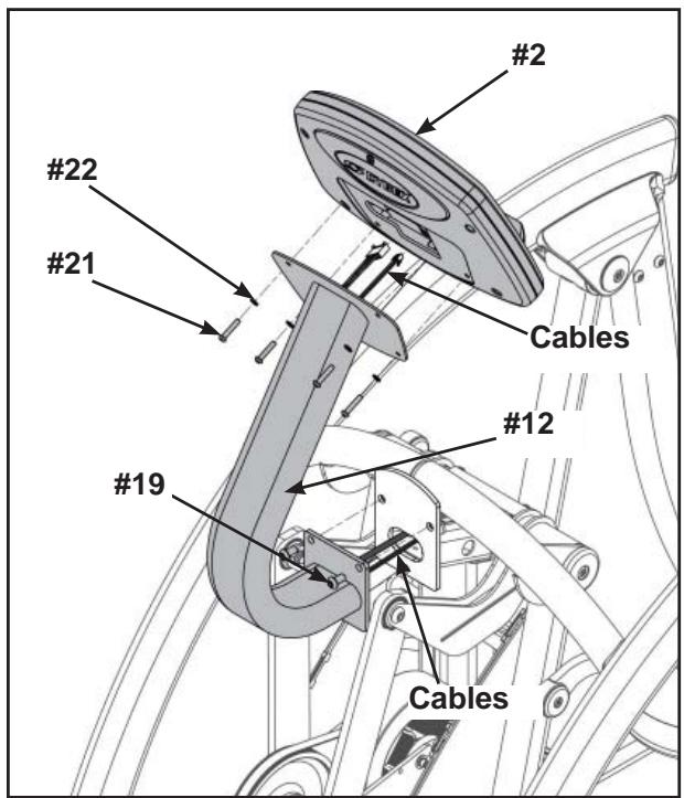
Figure 4
7. Attach the console assembly.
A. Locate console assembly (#2) and four BHSCS .250-20 x 1.250 (#21) and four lock washers (#22).
B. Connect the console and heart rate cables exiting top of the console support bracket (#12) to the console (#2). See Figure 4.
C. Position console assembly (#2) and hand thread each of the four BHCS .250-20 (#21) with four lock washers (#22). See Figure 4.
NOTE: Verify cables are not pinched.
D. Using the 5 / 32" Allen wrench (#26) provided, secure the console (#2) to the console support bracket (#12) with the four lock washers (#22) and four BHSCS .250 x 1.250 (#21).
8. Attach the left upper cover.
A. Locate the upper left side cover (#9) and one Phillips screw #8 X .625 BLK (#17).
B. Place the upper left side cover (#9) in position on mainframe and hand thread the Phillips screw #8 X .625 BLK (#17). See Figure 5.
NOTE: Ensure the locking connectors are securely in place. See Figure 5.
C. Using a Phillips head screwdriver, securely fasten the Phillips screw #8 X .625 BLK (#17).
D. Repeat steps 8A through 8C for right upper cover.
9. Attach top cover.
A. Locate top cover (#11) and one Phillips screw #8 X .625 BLK (#17).
B. Place the top cover (#11) in the correct position on the main frame assembly and hand thread the Phillips screw #8 X .625 BLK.(#17) See Figure 6.
C. Using a Phillips head screwdriver, securely fasten the Phillips screw #8 X .625 BLK (#17).
10. Attach front cover.
A. Locate front cover (#8) and four Philips screws #8 X .625 (#17).
B. Place the front cover (#8) in the correct position on the main frame assembly and hand thread the four Phillips screws #8 X .625 BLK (#17). See Figure 7.
C. Using a Phillips head screwdriver, securely fasten the four Philips screws #8 X .625 BLK (#17).
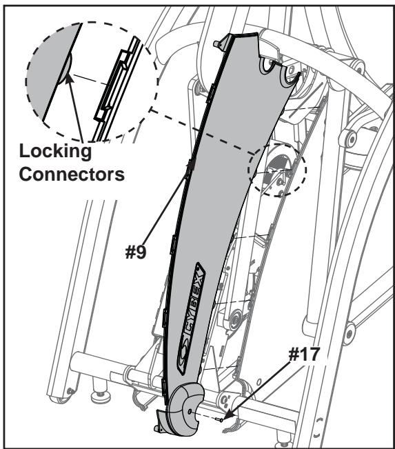
Figure 5
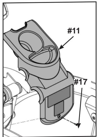
Figure 6
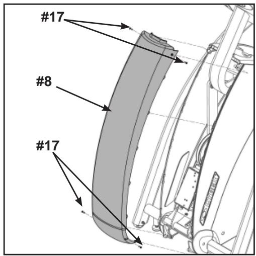
Figure 7
11. Attach the handles.
A. Locate the left (#13) and right (#14) handles, pivot shaft (#15), two BHSCS .375-16 x .50 (#18) and two washers (#23).
B. Position left (#13) and right (#14) handles vertically.
C. Position right handle (#14) to align opening with mainframe opening. See Figure 8.
D. Insert pivot shaft (#15) into opening of right handle (#14). See figure 8.
E. Position left handle (#13) to align the handle openings with the mainframe opening.
F. Push pivot shaft (#15) through opening.
G. Apply loctite (#16) to screws and into where screws will be threaded.
H. Using both 7 / 32" allen wrenches provided (#27), secure pivot shaft to handles using two BHSCS .375-16 x .50 screws (#18) and two washers (#23). NOTE: Handles will wobble if not securely tightened.
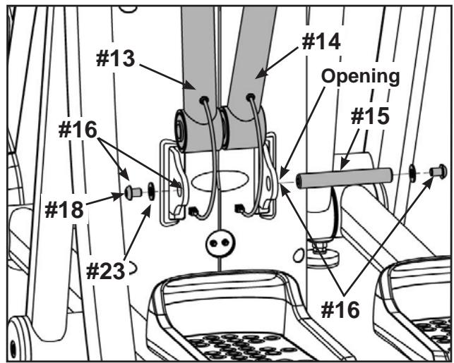
Figure 8
12. Attach S-Links.
A. Locate right S-Link on mainframe assembly. See Figure 9.
B. Locate a BHSCS .250-20 x .625 (#20), a washer (#25), end cap (#24) and spacer (#28).
C. Apply loctite (#16) to BHSCS and into where the screw will be threaded. See Figure 9.
D. Lift right S-Link and using the 5/32" Allen Wrench (#26) provided, secure the S-Link to handrail using BHSCS (#20), washer (#25) end cap (#24) and spacer (#28) located in step 12B. See Figure 9.
E. Repeat steps 12A through 12D for left side.
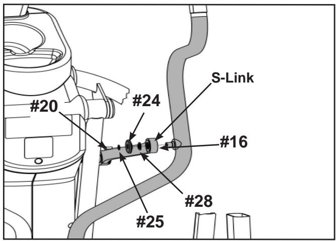
Figure 9
13. Connect contact heart cables.
A. Locate left and right heart rate wiring exiting from the handles.
B. Plug heart rate cables into main frame sockets. See Figure 10.
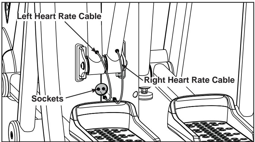
Figure 10
14. Attach the foot pads.
A. Have one person lift the unit while a second person places a foot pad (#3) under each of the two back feet. See Figure 11.
15. Level the unit.
A. Confirm that the unit is on a level surface. If it is not, use a 9/16" open-end wrench to adjust the leveling feet up or down. See Figure 12.
16. Visually inspect the unit.
A. Carefully remove any package material from arms and rest of unit.
B. Carefully examine the unit to ensure that the assembly is correct and complete.
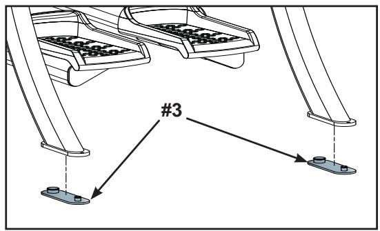
Figure 11
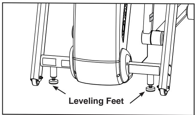
Figure 12

WARNING: Be sure that all electrical requirements are met as indicated in the specifications at the front of the manual and at the beginning of this chapter prior to proceeding.
Testing the Operation
Use the following instructions to test the full resistance and incline range of the unit.
- Plug the power cord into a power outlet from a grounded circuit as described under Electrical Requirements in this chapter. NOTE: Coil up the remainder of the power cord and place it out of the way, under the front of the unit.
- The control panel will light up and be in the Dormant Mode.
- Hold the handles to steady yourself while you step into the foot plates.
- Press the Quick Start key.
- Begin striding.
- Run the unit through its full resistance range. First press the Resistance + key until the unit reaches its highest load (the display will show "80"). Then press the Resistance - key until the unit reaches its lowest load; the display will show "0". As you stride, you will feel the resistance change.
NOTE: When the unit reaches the set incline and resistance, the displays will stop flashing and remain steadily illuminated to indicate that the desired settings have been reached.
- Run the unit through its full incline range. First press the Incline key until the unit reaches its highest incline (the display will show "10"). Then press the Incline V key until the unit reaches its lowest incline (the display will show "0").

WARNING: Wait until all moving parts come to a complete stop before dismounting.
- Press Pause/end twice to bring the incline back to its start position, end the workout review and return the display to Dormant Mode.
- Wait until foot plates come to a complete stop before dismounting the unit. Hold the handles to steady yourself while you step off the unit.
Setting Operation Options
- Enter Test Mode by holding Pause/end key. The display will read "425A".
NOTE: After changing any value, you must press Enter to save that value. When you press enter the display will read "upd" (updated) to confirm your selection.
2. Press the Weight key to set options, change values with keys and press Enter to save your selection. Each time you press Weight the next set of data is displayed in the following order.
Unit - Choices are "Eng" (English) or "Euro" (metric) measurements. English is the default.
Line: - This is the frequency of the power line that supplies power to your unit. The default setting is 50 Hz for metric consoles and 60 Hz for English consoles. NOTE: If you have an English console and a 50 Hz power line frequency, then you must change the default setting from 60 Hz to 50 Hz for the proper elevation frequency.
Scan - This turns on or off the data readout scan (unless a specific data key is pressed during a workout). Default is on.
Def - This is the default time for time based programs if a user doesn't re-set Time. For example, if you press Time you can decrease or increase the set workout time up to the amount that the Max time is set. Choices (in minutes) include: 20, 30, 40, 50 and 60. Default is 20.
Max - This is the maximum amount of time the unit can run per use. You can limit the users time or choose "none" for unlimited time. Choices (in minutes) include: 20, 30, 40, 50, 60, 90, 120 and "none" for no time limit. Default is 60.
Idle (or Workflow Review): - This is how long the unit retains and displays your current workout data during a pause in the workout or after a workout. Choices include: 20 seconds; 30 seconds; 40 seconds; 1 minute and 5 minutes; default is 20 seconds.
PD (Presence Detect) - This is the amount of time the unit will continue the program if the user steps off the pedals or stops moving. Time options are between 5 and 60 seconds. Default is 5 seconds.
NOTE: See Presence Detect in Chapter 3 for further details.
- To exit Test Mode press the Pause/end key once.
Your unit is now ready for use. Follow the instructions in the Operation chapter to learn how to operate the unit.
6 - Customer Service
Contacting Service
Hours of phone service are Monday through Friday from 8:30 a.m. to 6:00 p.m. Eastern Standard Time.
For Cybex customers living in the USA, contact Cybex Customer Service at 888-462-9239.
For Cybex customers living outside the USA, contact Cybex Customer Service at 508-533-4300 or fax 508-533-5183.
Find information on the web at www.cybexinternational.com or by e-mail at techhelp@cybexintl.com.
Serial Number and Voltage
Your serial number and voltage can be found on the front of the unit. See Figure 1.
For your convenience record your serial number and voltage below so that you will have it ready if you call Cybex Customer Service.
Serial Number _ Voltage _
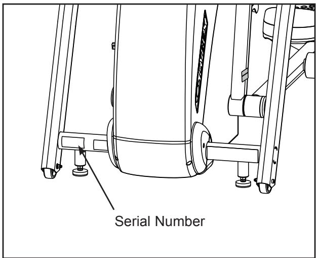
Figure 1
Return Material Authorization (RMA)
The Return Material Authorization (RMA) system outlines the procedures to follow when returning material for replacement, repair, or credit. The system assures that returned materials are properly handled and analyzed. Follow the following procedures carefully.
Contact your authorized Cybex dealer on all warranty-related matters. Your local Cybex dealer will request an RMA from Cybex, if applicable. Under no circumstances will defective parts or equipment be accepted by Cybex without proper RMA and an Automated Return Service (ARS) label.
- Call the Customer Service hotline listed on Page 6-1 for the return of any item that is defective.
- Provide the technician with a detailed description of the problem you are having or the defect in the item you wish to return.
- Provide the model and serial number. The serial number is located on the front of the unit as shown in Figure 1. The serial number begins with a letter, for example: R09-101331100.
- At Cybex's discretion, the technician may request that you return the problem part(s) to Cybex for evaluation and repair or replacement. The technician will assign you an RMA number and will send you an ARS label. The ARS label and RMA number must be clearly displayed on the outside of the package that contains the item(s) to be returned. Include a description of the problem, the serial number of the unit and the name and address of the owner in the package along with the part(s).
- Forward the package through UPS to Cybex.
Attn: Customer Service Department
Cybex International, Inc.
1975 24th Ave SW
Owatonna MN 55060, USA
NOTE: Merchandise returned without an RMA number on the outside of the package or shipments sent C.O.D. will not be accepted by the Cybex receiving department.
Damaged Parts
Materials damaged in shipment should not be returned for credit. Shipping damages are the responsibility of the carrier (UPS, Federal Express, trucking companies, etc.).
Apparent Damage - Upon receipt of your shipment, check all boxes carefully. Any damage seen with a visual check must be noted on the freight bill and signed by the carrier's agent. Failure to do so will result in the carrier's refusal to honor your damage claim. The carrier will provide you with the required forms for filing such claims.
Concealed Damage - Damage not seen with a visual check upon receipt of a shipment but noticed later must be reported to the carrier as soon as possible. Upon discovery of the damage, a written or phone request to the carrier asking them to perform an inspection of the materials must be made within ten days of the date of delivery. Keep all shipping containers and packing materials: they will be needed as part of the inspection process. The carrier will provide you with an inspection report and the necessary forms for filing a concealed damage claim. Concealed damage is the carrier's responsibility.
Ordering Parts
Fax orders to 508-533-5183. To speak with a customer service representative, call 888-462-9239 (for customers living within the USA) or 508-533-4300 (for customers outside the USA).
CAUTION
Use only Cybex replacement parts when servicing.
Failure to do so could result in personal injury.
Cybex will void warranty if non-Cybex replacement parts are used.
Main Assembly
| ITEM | QTY | PART NO. | DESCRIPTION |
| A1 | 2 | 425A-483 | END CAP |
| A2 | 2 | 12090-322 | FOOT PAD |
| A3 | 1 | 425A-101 | DRIVE FRAME ASSEMBLY |
| A4 | 1 | 425A-200 | MAIN FRAME |
| A5 | 1 | 425A-201 | FRONT LEG RH |
| A6 | 1 | 425A-202 | FRONT LEG LH |
| A7 | 2 | 425A-203 | REAR LEG |
| A8 | 1 | 425A-204 | FOOT BAR LH |
| A9 | 1 | 425A-205 | FOOT BAR RH |
| A10 | 2 | 425A-207 | S LINK |
| A11 | 1 | 425A-208 | INPUT HANDLE RH |
| A12 | 1 | 425A-209 | INPUT HANDLE LH |
| A13 | 2 | 425A-210 | DRIVE LINK |
| A14 | 2 | 425A-212 | REAR LEG |
| A15 | 2 | 425A-319 | ASSY, CRANK ARM |
| A16 | 2 | 425A-359 | FOOT PLATE |
| A17 | 2 | 425A-360 | TOE CAP |
| A18 | 2 | 425A-378 | GRIP, CHR, FRONT |
| A19 | 2 | 425A-379 | GRIP, CHR, BACK |
| A20 | 2 | 425A-487 | TUBE, SPACER |
| A21 | 2 | 425A-444 | PIN, PIVOT |
| A22 | 2 | 425A-484 | END CAP |
| A23 | 6 | 425A-485 | END CAP |
| A24 | 1 | 425A-216 | SHAFT, DRIVE PIVOT |
| A25 | 1 | 425A-448 | PIN, PIVOT |
| A26 | 1 | 425A-449 | PIVOT SHAFT |
| A27 | 1 | 425A-450 | BLOCK, CLAMP |
| A28 | 1 | 425A-451 | MAGNETIC SENSOR |
| A29 | 4 | 425A-482 | END CAP |
| A30 | 1 | 425A-457 | BRACKET COVER |
| A31 | 1 | 425A-458 | COVER, TOP |
| A32 | 1 | 425A-459 | COVER FRONT |
| A33 | 1 | 425A-460 | COVER SIDE UPPER RIGHT |
| A34 | 1 | 425A-461 | COVER SIDE LOWER RIGHT |
| A35 | 1 | 425A-462 | COVER SIDE UPPER LEFT |
| A36 | 1 | 425A-463 | COVER SIDE LOWER LEFT |
| A37 | 1 | 425A-465 | INSERT, PLASTIC 1.75 OD |
| A38 | 4 | 425A-468 | RETainer |
| A39 | 2 | 425A-469 | DECAL, CYBEX |
| A40 | 1 | 425A-470 | COVER, LCB |
| A41 | 2 | 425A-489 | SPACER |
| A42 | 2 | 425A-488 | SPACER |
| A43 | 2 | 425A-486 | SPACER |
| A44 | 1 | 425A-479 | DECAL, LCB COVER |
| A45 | 1 | 610A-104 | CABLE,CHR CHASSIS GND |
| A46 | 2 | AW-19615 | CABLE, 425A, CHR GRIP |
| A47 | 1 | AW-19616 | HARNESS, 425A CHR, FRAME |
| A48 | 4 | BR030225 | RETAINING RING 1.438 INTERNAL |
| A49 | 1 | CM000240 | DECAL, DISCONNECT POWER 7 LanguAGES |
| A50 | 2 | CW-17231 | WHEEL, TENSIONER |
| A51 | 1 | EC-19978 | SENSOR, WHR AND CHR COMBO |
| A52 | 4 | FB030232 | BEARING, RADIAL 17 mm EXTENDED RACE |
| A53 | 4 | FB030244 | BEARING, RADIAL BALL .50 ID X 1.688 OD |
| A54 | 8 | FB030247 | BEARING, RADIAL 25MM EXTENDED RACE |
| A55 | 4 | FB030248 | BEARING, SPHERICAL 15MM |
| A56 | 8 | FB030253 | BEARING, RADIAL 30 MM EXTENDED RACE |
| A57 | 8 | FC030003 | TOLERANCE RING |
| A58 | 4 | FC030004 | TOLERANCE RING 42 (1.653) ID |
| A59 | 4 | FC030005 | TOLERANCE RING 1.378 ID |
| A60 | 4 | FC030006 | TOLERANCE RING 1.575 ID |
| A61 | 8 | FC030007 | TOLERANCE RING 2.047 ID |
| A62 | 1 | FT-17242 | SLEEVE, ELEVATION MOUNTING, TOP |
| ITEM | QTY | PART NO. | DESCRIPTION |
| A63 | 1 | FT-17243 | SLEEVE, ELEVATION MOUNTING, BOTTOM |
| A64 | 4 | HC620414 | BHSCS .250-20 X .625 |
| A65 | REMOVED 3/07 | ||
| A66 | 23 | HC700415 | BHSCS .375-16 X .75 |
| A67 | 6 | HC700416 | BHSCS .375-16 X .875 |
| A68 | 4 | HC700426 | BHSCS .375-16 X 2.00 |
| A69 | 1 | HC701226 | BOLT, HHCS .375-16 x 2.0 |
| A70 | 1 | HC701230 | SCREW, HHCS .375-16 x 2.50 |
| A71 | 2 | HC702822 | SHCS .375-16 X 1.50 |
| A72 | 11 | HF540200 | GROMMET, NYLON |
| A73 | 2 | HG700022 | LEVELING GLIDE, .375-16 |
| A74 | 1 | HN586300 | NUT, K-LOCK 10-32 ZINC PLATED |
| A75 | 3 | HN624901 | LOCKNUT, .250-20 NYLON BLK ZN |
| A76 | 2 | HN704000 | HEX NUT .375-16 |
| A77 | 2 | HN704902 | LOCKNUT, .375-16 NYLON |
| A78 | 2 | HN784901 | NYLON LOCKNUT .500-13 THIN |
| A79 | 4 | HS008006 | WASHER NYL .908 1.500 .050 |
| A80 | 1 | HS047300 | LOCKWASHER, EXTERNAL NO. 10 |
| A81 | 2 | HS307600 | WASHER SAE .250 |
| A82 | 2 | HS328300 | LOCKWASHER SPLIT .312 |
| A83 | 2 | HS347600 | WASHER, SAE .375 |
| A84 | 2 | HT102214 | PHIL, HEX, WASHER HD, TYPE 23, 10-24 |
| A85 | REMOVED 3/07 | ||
| A86 | 19 | HT542514 | PN HD PHIL SC # 8 X .625 BLK |
| A87 | 8 | HT552512 | PAN HD PHIL HD SELF TAPPING, 8-16 x .50 TYPE WB |
| A88 | 8 | HT582510 | TAP SC NO 10 X .375 PN HD PHIL |
| A89 | 2 | HX-17143 | RING RETAINING, INTERNAL, .500-168 |
| A90 | REMOVED 3/07 | ||
| A91 | 2 | JC620412 | BHSCS .250-20 X .50 |
| A92 | 2 | JC700412 | BHSCS .375-16 X .50 |
| A93 | 2 | JC780422 | BHSCS .500-13 X 1.50 |
| A94 | 2 | JD623324 | BOLT, SHOULDER .312 x 1.75 .250-20 UNC |
| A95 | 2 | PP130004 | INSERT, DOMED PLASTIC |
| A96 | 1 | YD000027 | TAPE, DOUBLE BACK .75 X 2.00 |
| A97 | 1 | AW-19624 | POWER CORD 115V |
| A97 | 1 | AW-19625 | POWER CORD 230V |
| A97 | 1 | AW-19626 | POWER CORD 230V |
| A97 | 1 | AW-19627 | POWER CORD 100V |
| A98 | 1 | HX-19841 | CLAMP, STRAIN RELIEF .250 ID |
| A98 | 1 | HX-19842 | CLAMP, STRAIN RELIEF .313 ID |
| A99 | 1 | HT552510 | SCREW |
| A100 | 1 | 425A-206 | CONSOLE MOUNT |
| A101 | 4 | HS307400 | LOCKWASHER INT TOOTH .250 SS |
| A102 | 4 | HX620420 | BHSCS .250-20 X 1.250 |
| A103 | 1 | MR-19609 | MOTOR ELEVATION 115V |
| A103 | 1 | MR-19610 | MOTOR ELEVATION 230V |
| A104 | 1 | 425A-395 | WARRANTY SHEET (NOT SHOWN) |
| A105 | 1 | 425A-396 | INSTALLATION POSTER (NOT SHOWN) |
| A106 | 1 | 5425A-4 | OWNER'S MANUAL (NOT SHOWN) |
| A107 | 1 | 425A-495-X* | WARNING DECAL |
| A108 | 1 | DE-17218-X* | HEART RATE ZONE DECAL |
| A109 | 4 | DE-17219-X* | CAUTION DECAL |
| A110 | 1 | DE-17266 | UL DOMESTIC DECAL (NOT SHOWN) |
| A111 | 1 | 425A-494 | ETL LABEL |
| A111 | 1 | CM000242 | CE DECAL |
| A112 | 1 | CM000241 | FCC DECAL |
| A113 | 1 | HN625200 | REMOVED 4/07 |
| A114 | 1 | HS387700 | WASHER, SAE .500 |
| A115 | 1 | JC780420 | BHSCS .250-20 X .75 |
| A116 | 1 | HC622815 | BHSCS .500-13 X 1.25 |
| A117 | 10 | 425A-481 | SPACER |
| A118 | 4 | 600A-311 | SPACER |
| A119 | 4 | HS307601 | WASHER, FLAT .281ID X .500OD X .062 |
| A120 | 1 | 600A-362 | BIOSIG PATENT LABEL |
| A121 | 1 | 630A-351 | WEEE SYMBOL DECAL |
| A122 | 7 | EW000028 | CABLE TIE |
| A123 | 1 | EW000029 | CABLE TIE |
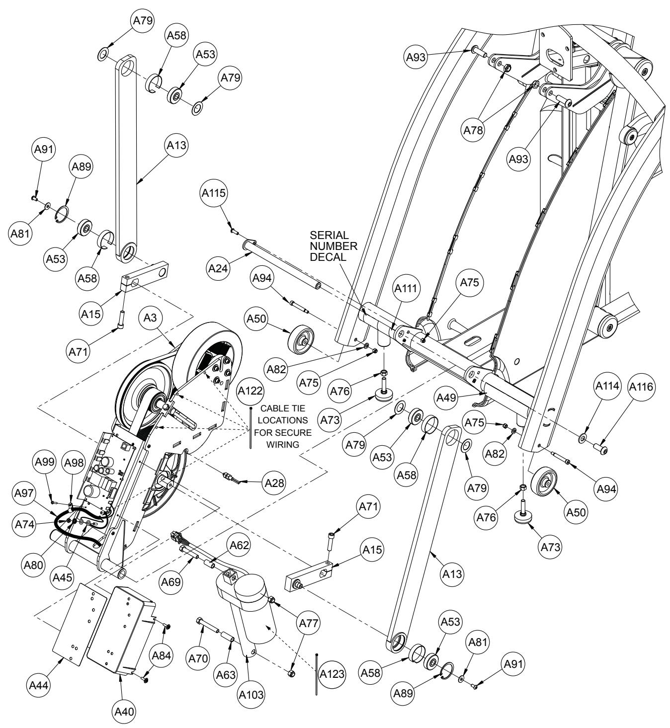
Main Frame Assembly
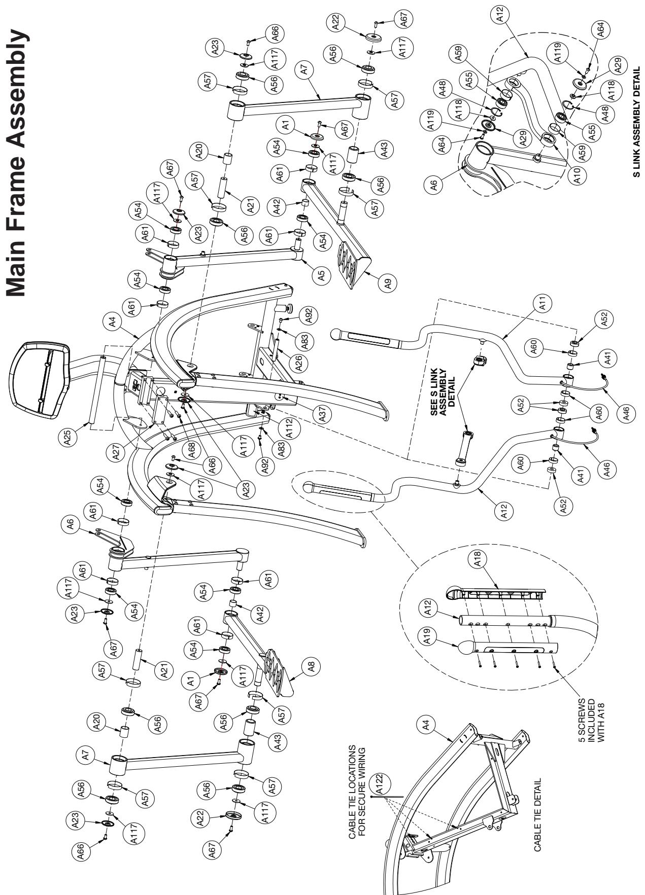
Main Frame Assembly
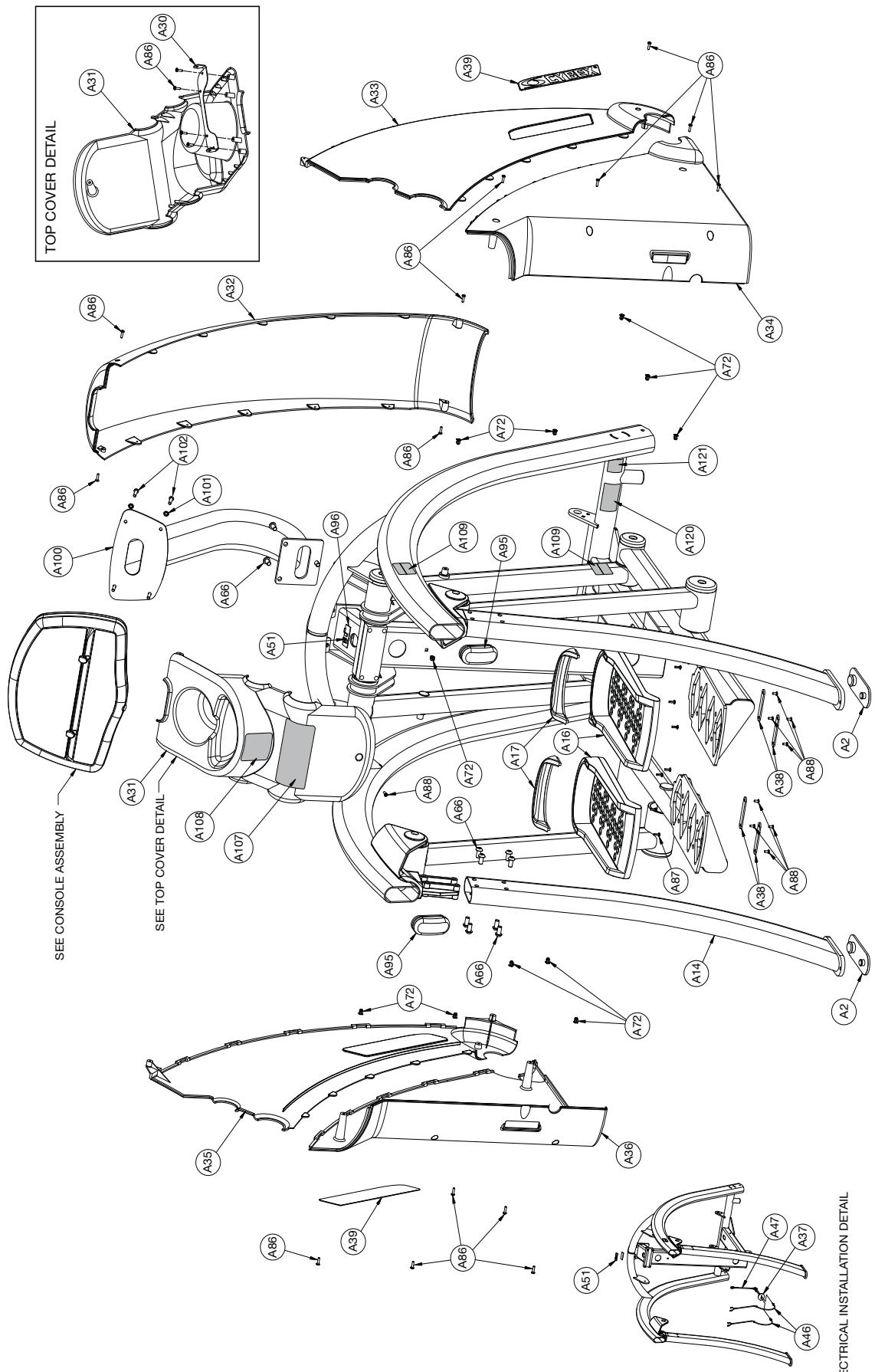
ELECTRICAL INSTALLATION DETAIL
Console Assembly
| ITEM | QTY | PART NO. | DESCRIPTION |
| B1 | 1 | 610A-396 | PLATE, CONSOLE MOUNTING |
| B2 | 1 | AD-21513-Q | PCA, 425A MAIN DISPLAY |
| B3 | 1 | AW-19617 | HARNESS, 425A HR CONSOLE |
| B4 | 1 | AW-19619 | CABLE, 425A CONSOLE RJ45 |
| B5 | 1 | HJ582515 | SCREW, SEMS, 10-32 X .75 PHIL PAN, BLK ZINC |
| B6 | 7 | HT552509 | SCREW, TAP 8-16 x .31 PLASTITE |
| B7 | 4 | HT552512 | PAN HD PHIL HD SELF TAPPING, 8-16 x .50 TYPE WB |
| B8 | 4 | HT552515 | PAN HD PHIL HD SELF TAPPING, 8-16 x .75, TYPE WB BLACK |
| B9 | 1 | PP080207 | INSERT, PLASTIC .437 DIA 11 GA |
| B10 | 1 | PP620003 | CONSOLE, FRONT PLASTIC |
| B11 | 1 | PP620004 | CONSOLE, REAR PLASTIC |
| B12 | 1 | PP620005 | COVER, CONSOLE BATTERY DOOR |
| B13 | 2 | PP620006 | TAB, BOOK HOLDER |
| B14 | 1 | SW-21556-X* | MEMBRANE, 425A TOP |
| B15 | 1 | SW-21557-4 | MEMBRANE, 425A BTM W/O AV |
| B15 | 1 | SW-21558-X* | MEMBRANE, 425A BTM W AV |
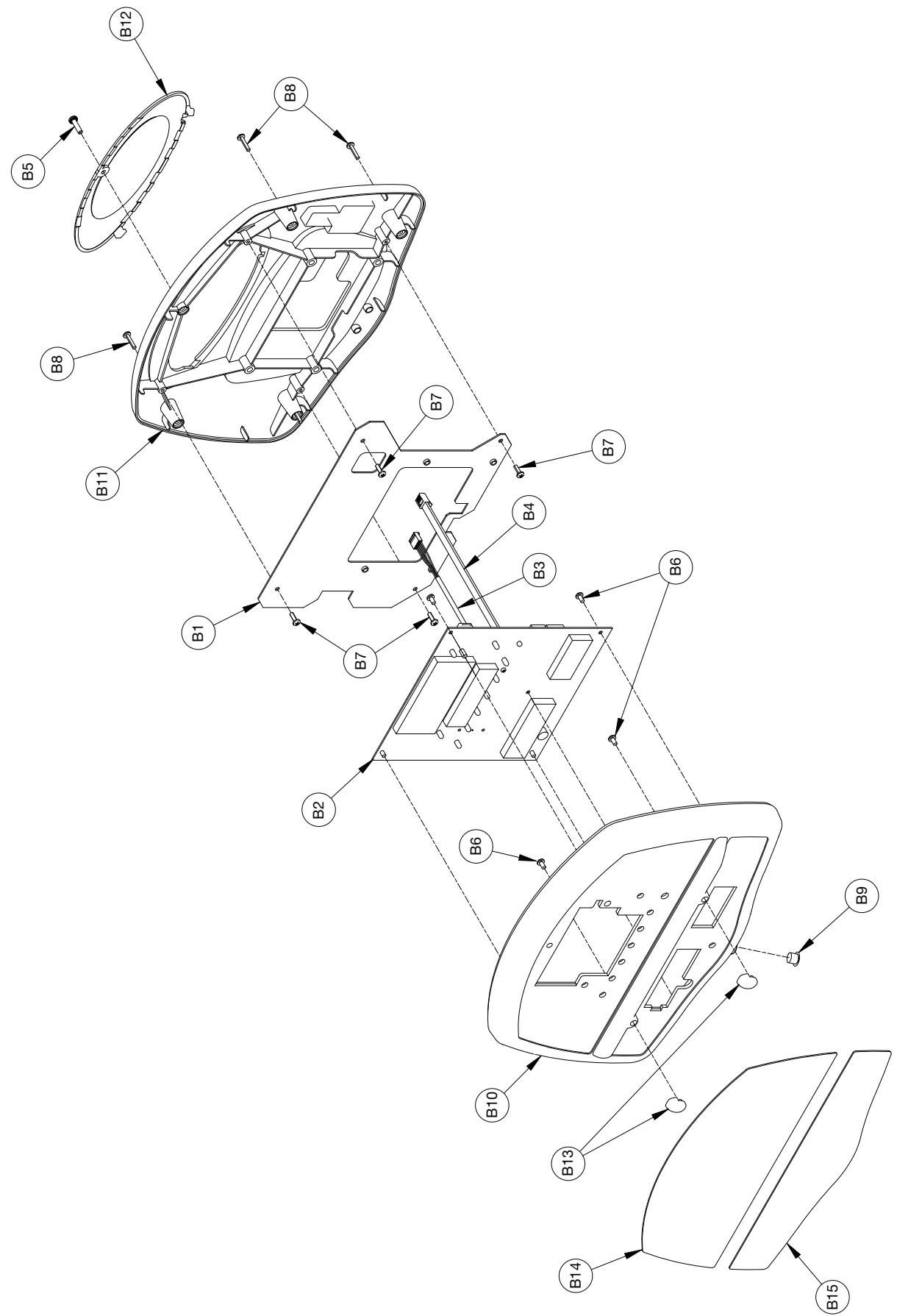
Console Assembly
Drive Frame Assembly
| ITEM | QTY | PART NO. | DESCRIPTION |
| C1 | 1 | 425A-211 | W BOX |
| C2 | 1 | 425A-313 | SHAFT |
| C3 | 1 | 425A-320 | PULLEY, SECONDARY DRIVE |
| C4 | 1 | 425A-322 | SHAFT, SECONDARY DRIVE |
| C5 | 1 | 425A-337 | PULLEY, PRIMARY DRIVE |
| C6 | 2 | 425A-364 | MAGNET |
| C7 | 2 | 425A-373 | ADJUSTER, BELT TENSION |
| C8 | 1 | 425A-455 | BELT, PRIMARY DRIVE |
| C9 | 1 | 425A-456 | BELT, SECONDARY DRIVE |
| C10 | 2 | 600A-340 | BEARING, 1.00 INCH PILLOW BLOCK |
| C11 | 1 | AD-19612 | PCA, 425A CONTROLLER |
| C12 | 2 | BR030227 | RETAINING RING, 20 MM EXTERNAL |
| C13 | 2 | FB030254 | RADIAL BEARING 20 MM |
| C14 | 2 | FB130212 | BUSHING, FLANGE .75 ID x .875 OD x .75 LG |
| C15 | 2 | HC321258 | SCREW, HEX HEAD CAP .312-18 x 6.000 |
| C16 | 4 | HC622815 | SHCS .250-20 X .750 |
| C17 | 4 | HC661217 | HX HD CAP SCREW .312-18 X 1.00 |
| C18 | 4 | HC701220 | BOLT, HHCS .375-16 x 1.25 |
| C19 | 4 | HJ582515 | SCREW, SEMS 10-32 x .75 PHIL PAN, BLACK ZINC |
| C20 | 1 | HN704901 | LOCKNUT, .375-16 NYLON |
| C21 | 4 | HS307600 | WASHER SAE .250 |
| C22 | 4 | HS308300 | SPLIT LOCKWASHER .250 |
| C23 | HS347600 | WASHER, SAE .375 REMOVED 3-22-10 | |
| C24 | 5 | HS347700 | WASHER, USS .375 |
| C25 | 4 | HS760100 | SPRING RETAINING WASHER |
| C26 | 2 | HX-17023 | PIN, SPRING .1875 x .75 LG, TYPE 420 |
| C27 | 2 | HS328300 | LOCKWASHER INT TOOTH .312 |
| C28 | 1 | MR-19541 | ASSEMBLY, ECB (SINGLE ROW BEARING) |
| C29 | 1 | CM000237 | LABEL, SAFETY GROUND |
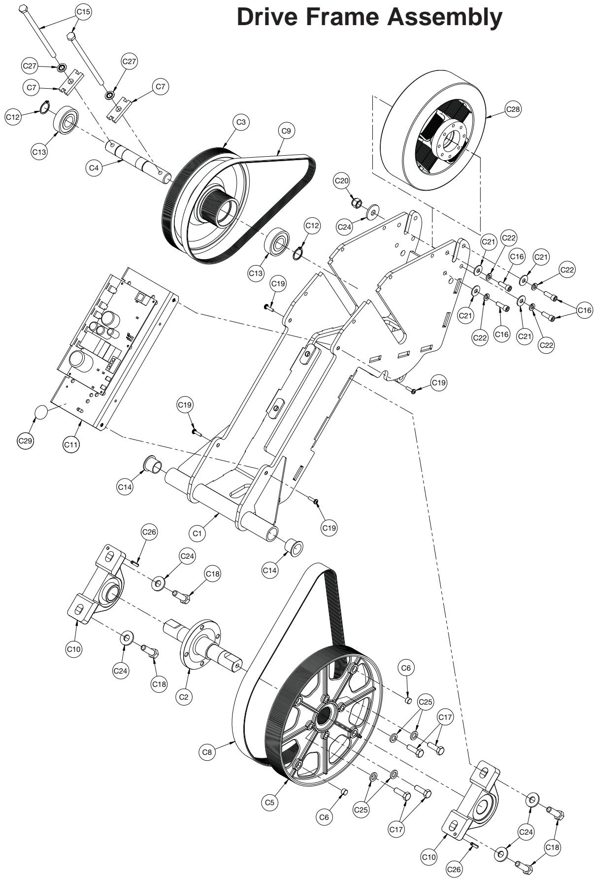
Drive Frame Assembly
This page intentionally left blank
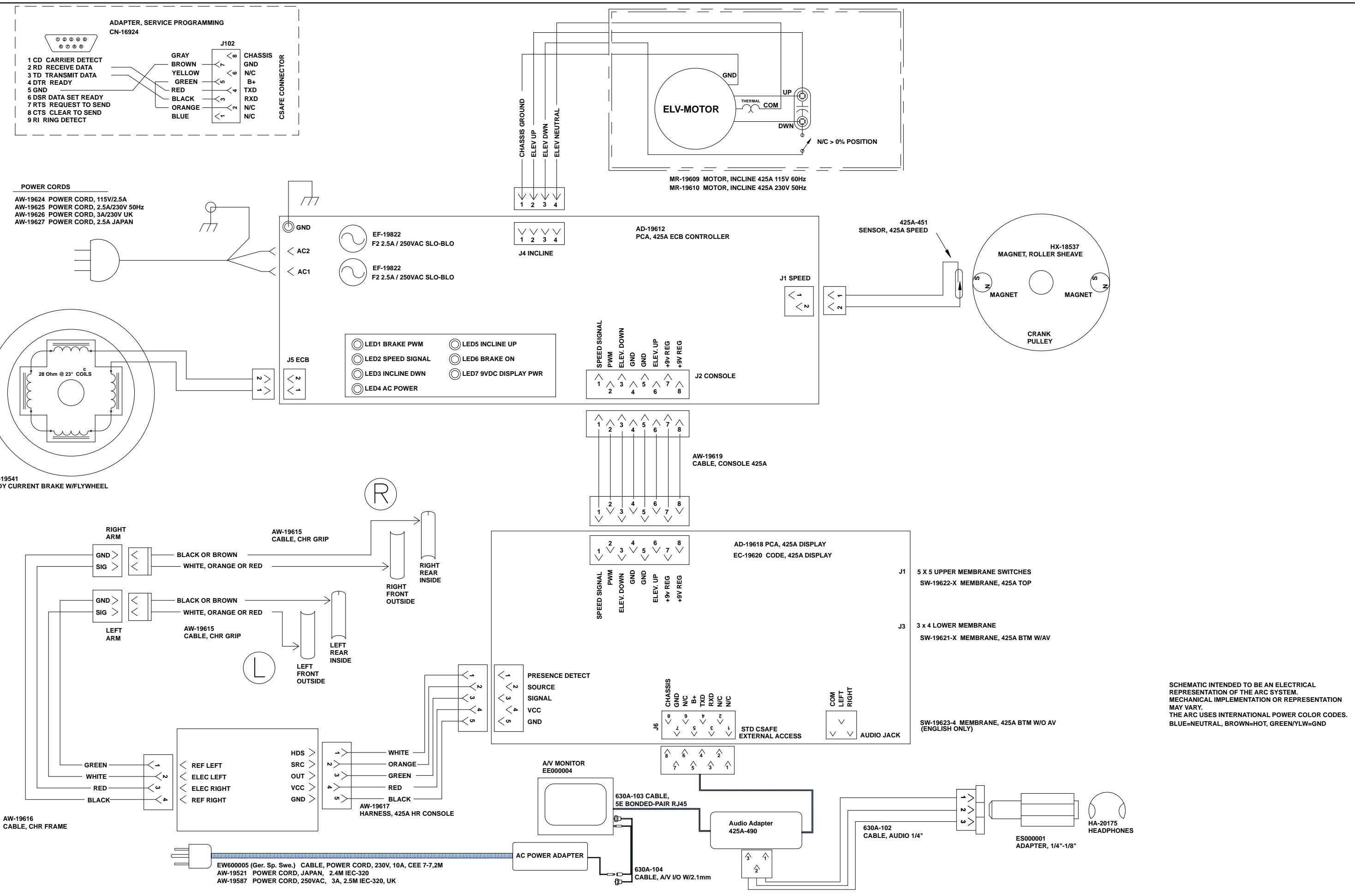
Cybex Arc Trainer 425A Owner's Manual