
PLX 1104 - Audio Amplifier QSC AUDIO - Free user manual and instructions
Find the device manual for free PLX 1104 QSC AUDIO in PDF.
| Product type | Professional audio amplifier |
| Brand | QSC Audio |
| Model | PLX 1104 |
| Category | Audio amplifier |
| Dimensions (W x H x D) | 48,3 cm x 8,9 cm x 25,7 cm |
| Net weight | 5,9 kg |
| Gross weight (shipping) | 8,2 kg |
| Power supply | 100 V, 120 V or 220-240 V, 50-60 Hz (depending on factory configuration) |
| Output power (8 ohms, stereo, 20 Hz-20 kHz, 0.05% THD) | 310 W per channel |
| Output power (4 ohms, stereo, 20 Hz-20 kHz, 0.05% THD) | 500 W per channel |
| Minimum load impedance | 4 ohms per channel |
| Voltage gain | 32.5 dB |
| Input sensitivity (for rated power 8 ohms) | 1.18 Vrms (+3.7 dBu) |
| Input impedance | 20 kOhms (balanced), 10 kOhms (unbalanced) |
| Frequency response | 20 Hz - 20 kHz, ±0.5 dB |
| Signal-to-noise ratio (unweighted, 20 Hz-20 kHz) | -108 dB |
| Damping factor (8 ohms) | >200 |
| Distortion (SMPTE-IM) | 0.02% |
| Input connectors | XLR female and TRS 6.35 mm (balanced jack) |
| Output connectors | Speakon (channel 1: 4 wires, channel 2: 2 wires) |
| Cooling | Variable speed fan, airflow rear to front |
| Protections | Short circuit, open circuit, thermal, RF, ultrasonic, amplitude limiter |
| Indicators | PWR (blue), SIGNAL (green), -10 dB (green), CLIP (red) |
| Controls | On/off switch, gain (21 detents), input parallel jumper |
| Maintenance and cleaning | Clean with a dry cloth, do not obstruct vents |
| Spare parts and repairability | No user-serviceable parts, refer all servicing to qualified personnel |
| General information | PowerLight power supply technology, light weight, efficient cooling, 2U rack-mountable |
Frequently Asked Questions - PLX 1104 QSC AUDIO
User questions about PLX 1104 QSC AUDIO
0 question about this device. Answer the ones you know or ask your own.
Ask a new question about this device
Download the instructions for your Audio Amplifier in PDF format for free! Find your manual PLX 1104 - QSC AUDIO and take your electronic device back in hand. On this page are published all the documents necessary for the use of your device. PLX 1104 by QSC AUDIO.
USER MANUAL PLX 1104 QSC AUDIO
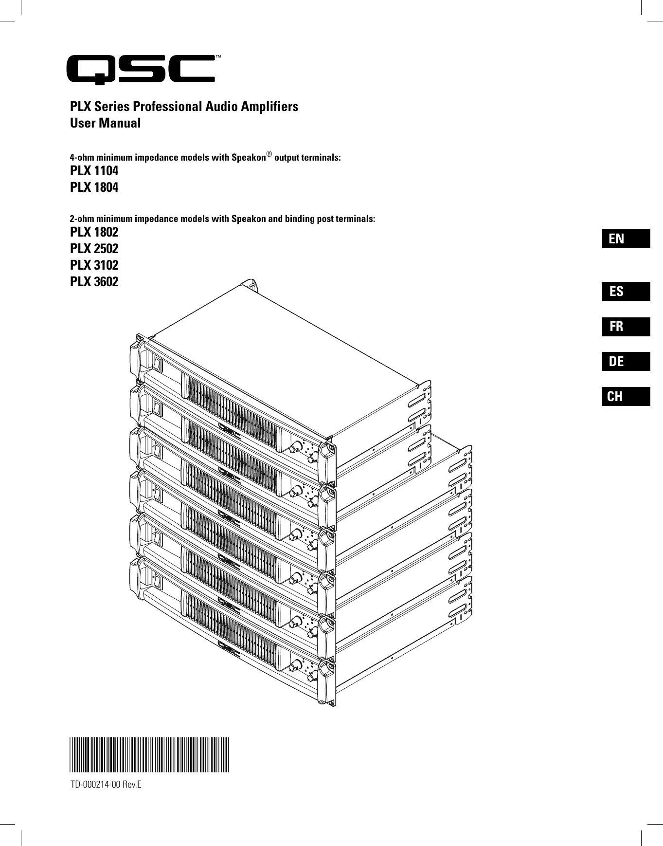
PLX Series Professional Audio Amplifiers
User Manual
4-ohm minimum impedance models with Speakon® output terminals:
PLX 1104
PLX 1804
2-ohm minimum impedance models with Speakon and binding post terminals:
PLX 1802
PLX 2502
PLX 3102
PLX 3602

Important Safety Precautions & Explanation of Symbols
1- Read these instructions.
2- Keep these instructions.
3-Heed all warnings.
4- Follow all instructions.
5- WARNING: To prevent fire or electric shock, do not expose this equipment to rain or moisture. Do not use this apparatus near water.
6- Clean only with a dry cloth.
7- Do not block any ventilation openings.
8- Do not install near any heat sources such as radiators, heat registers, stoves, or other apparatus (including amplifiers) that produce heat.
9- Do not defeat the safety purpose of the polarized or grounding-type plug. A polarized plug has two blades with one wider than the other. A grounding plug has two blades and a grounding prong. The wide blade or third prong are provided for your safety. If the provided plug does not fit your outlet, consult an electrician for the replacement of the obsolete outlet.
10- Protect the power cord from being walked on or pinched, particularly plugs, convenience receptacles, and the point where they exit from the apparatus.
11- Use only attachments/accessories specified by QSC Audio Products, LLC
12- Use only with hardware, brackets, stands, and components sold with the apparatus or by QSC Audio Products, LLC
13- Unplug the apparatus during lightning storms or when unused for long periods of time.
14- Refer all servicing to qualified service personnel. Servicing is required when the apparatus has been damaged in any way, such as power supply cord or plug is damaged, liquid has been spilled or objects have fallen into the apparatus, the apparatus has been exposed to rain or moisture, does not operate normally, or has been dropped.

The exclamation point within an equilateral triangle is intended to alert the user to the presence of important operating and maintenance (servicing) instructions in this manual.

The lightning flashes printed next to the OUTPUT terminals of the amplifier are intended to alert the user to the risk of hazardous energy. Output connectors that could pose a risk are marked with the lightning flash. Do not touch output terminals while amplifier power is on. Make all connections with amplifier turned off.

The lightning flash with arrowhead symbol within an equilateral triangle is intended to alert the user to the presence of uninsulated "dangerous" voltage within the product's enclosure that may be of sufficient magnitude to constitute a risk of electric shock to humans.

CAUTION: TO REDUCE THE RISK OF ELECTRIC SHOCK, DO NOT REMOVE THE COVER. NO USER-SERVICEABLE PARTS INSIDE. REFER SERVICING TO QUALIFIED PERSONNEL.

WARNING: To prevent fire or electric shock, do not expose this equipment to rain or moisture.
FCC INTERFERENCE STATEMENT
NOTE: This equipment has been tested and found to comply with the limits for a class B digital device, pursuant to part 15 of the FCC rules. These limits are designed to provide reasonable protection against harmful interference in a residential installation. This equipment generates, uses, and can radiate radio frequency energy and if not installed and used in accordance to the instructions, may cause harmful interference to radio communications. However, there is no guarantee that interference will not occur in a particular installation. If this equipment does cause harmful interference to radio or television reception, which can be determined by switching the equipment off and on, the user is encouraged to try to correct the interference by one or more of the following measures:
- Reorient or relocate the receiving antenna.
- Increase the separation between the equipment and the receiver.
- Connect the equipment into an outlet on a circuit different from that to which the receiver is connected.
- Consult the dealer or an experienced radio or TV technician for help.
Copyright 2006, QSC Audio Products, LLC
QSC® is a registered trademark of QSC Audio Products, LLC
"QSC" and the QSC logo are registered with the U.S. Patent and Trademark Office
Speakon® is a registered trademark of Neutrik Inc. All trademarks are the property of their respective owners.
Introduction
Thank you for purchasing this QSC power amplifier. Please read the following directions to obtain the best results. This manual covers all models of the PLX series. Illustrations show the PLX 1804 to be representative of the PLX 1104 and 1804 models, while the PLX 3602 illustration is representative of the PLX 1802, PLX 2502, PLX 3102, and PLX 3602 models.
The PLX 1104 and PLX 1804 models feature:
- 4-ohm minimum impedance
- Speakon loudspeaker connections
- QSC PowerLight high-performance, compact, and light weight switching power supply
- Complete amplifier protection
- XLR and 1/4-inch TRS balanced input connectors
- Gain controls are recessed and 21-step detented
Active inrush current limiting eliminates need for power sequencing - LED indicators for power, input signal presence, -10 dB, and clip/protect
Rear chassis tabs and front panel design protect controls and connectors
In addition, the PLX 1802, PLX 2502, PLX 3102, and PLX 3602 models feature:
-2-ohm minimum impedance
- Bridgeable output
- Binding post loudspeaker connections
-Clip limiter
- 33 Hz low frequency filter
- Low-cut/full-range/high-cut selector
- Stereo/bridge mode/parallel input selector
- Front panel LED indicators for parallel and bridge modes
Unpacking
Factory packed carton contains:
- PLX amplifier
- User's manual
Adhesive rubber feet (for non-rack mount applications) - IEC-type detachable power cord
Use the same type carton when shipping the amplifier.
Front Panel
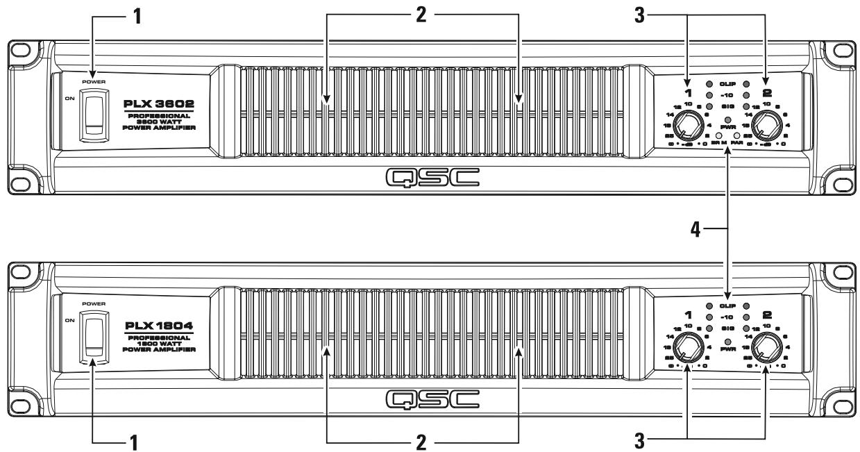
1-Power Switch
2-Cooling Air Exhaust Vents
3-LED Indicators
4- Gain Controls
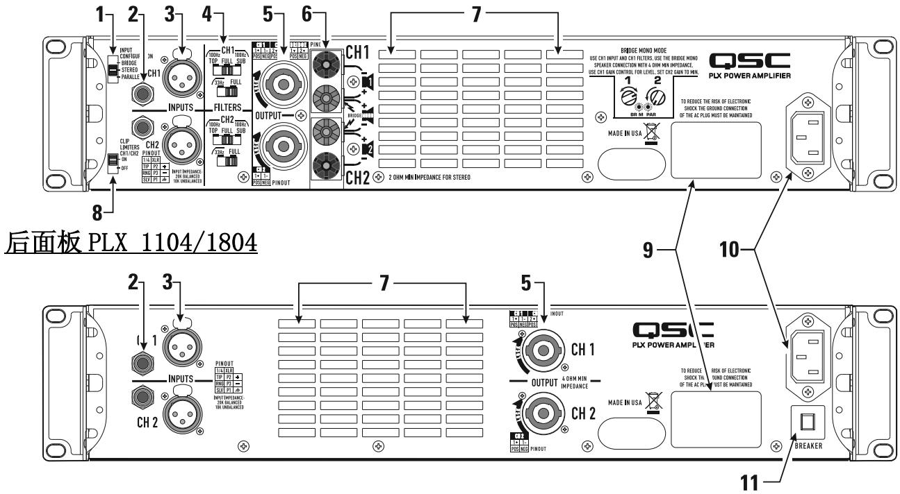
Rear Panel PLX 1802, PLX 2502, PLX 3102, PLX 3602

1- Input Configuration switch
2- 1/4-inch TRS input connectors
3-XLR female input connectors
4- Low Frequency Filter switches
5-Speakon output connectors
6- Binding post output connectors
7-Cooling air inlet vents
8-Clip Limiter switch
9- Serial number plate
10- IEC-type AC mains inlet
11-Circuit breaker, resettable
Rack Mounting
Use four screws and washers to mount the amplifier to the equipment rack rails. To use the amplifier outside a rack, attach the self-adhesive rubber feet to the bottom.
For portable, mobile, or other applications where the rack assembly may be moved, we strongly recommend supporting the rear of the amplifier. A rear rack ear kit is available from QSC's Technical Services Group.
The cast front panel includes finger grips at each end, making lifting and setting into the rack more comfortable.
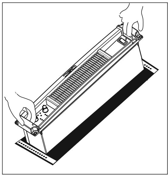
The front panel casting includes features for finger-lifting and gripping at each end.
Cooling
Air flows from the rack, into the back of the amplifier, and out the front. This keeps the rack cool. The fan automatically runs faster when the amp is working hard.

Do not block the front or rear air vents!
AC Mains Connection
Connect AC power to the IEC socket on the back of the amplifier. NOTE: Turn off the AC power switch before connecting AC power. Connect the AC mains plug to a suitable AC mains outlet.

The correct AC line voltage is shown on the serial number label, on the rear panel. Connecting to the wrong line voltage may damage the amplifier or increase the risk of electric shock.

The rear chassis ear can be used to retain the IEC power connector. After inserting the IEC block into the receptacle, use a wire-tie or similar device to secure the cord to the chassis ear.
Air flow in QSC amplifiers: Cool air is drawn into the rear of the amplifier by the cooling fan. Warm air exits the front of the amplifier.

Orient the IEC connector with the connector prongs in the socket, then push the connector firmly into the IEC socket until fully seated.

AC Mains Current Draw
The table at the right provides typical current draw for each model as a function of load and output power level. Units of measurement are amperes rms.

NOTE! Current draw shown is for 120 VAC line. For 230 VAC models, multiply values shown by 0.5.
- 1/8 power (pink noise) represents typical program with occasional clipping. Use this rating for most applications.
- 1/3 power (pink noise) represents severe program with heavy clipping.
Full power (sine) is continuous sine wave driven at 1% clipping. - PLX 1802, PLX 2502, PLX 3102, and PLX 3602 models: Thermal or overcurrent cutback limits duration of full power 2 ohm operation. Long term, active limiting to 30A at 120V.
- PLX 1104 and PLX 1804 models: Long-term, circuit breaker limited to 15A at 120V.
| Model | Load | Idle | 1/8 Power (pink noise) | 1/3 Power (pink noise) | Full Power (sine) |
| PLX 1104 | 8 Ohms (x2) | 0.9 | 5.0 | 8.0 | 12.6 |
| 4 Ohms (x2) | 0.9 | 8.0 | 12.4 | 21.0 | |
| PLX 1804 | 8 Ohms (x2) | 0.9 | 5.7 | 10.4 | 20.0 |
| 4 Ohms (x2) | 0.9 | 9.4 | 16.5 | 32.0 | |
| PLX 1802 | 8 Ohms (x2) | 0.9 | 5.0 | 7.7 | 12.6 |
| 4 Ohms (x2) | 0.9 | 8.7 | 12.3 | 21.3 | |
| 2 Ohms (x2) | 0.9 | 13.0 | 19.7 | 33.2 | |
| PLX 2502 | 8 Ohms (x2) | 0.9 | 5.0 | 8.2 | 15.5 |
| 4 Ohms (x2) | 0.9 | 7.5 | 12.6 | 25.0 | |
| 2 Ohms (x2) | 0.9 | 11.2 | 19.0 | 37.0 | |
| PLX 3102 | 8 Ohms (x2) | 0.9 | 6.0 | 10.7 | 21.0 |
| 4 Ohms (x2) | 0.9 | 9.5 | 16.5 | 33.0 | |
| 2 Ohms (x2) | 0.9 | 14.0 | 27.0 | 55.0 | |
| PLX 3602 | 8 Ohms (x2) | 0.9 | 7.7 | 13.0 | 25.0 |
| 4 Ohms (x2) | 0.9 | 11.5 | 19.5 | 40.0 | |
| 2 Ohms (x2) | 0.9 | 18.0 | 31.0 | 63.0 |
Input Configuration Switch (PLX 1802/2502/3102/3602 models only)
Select the input configuration by sliding the switch to the position which corresponds with the desired input configuration.
- Bridge-upper position
- Stereo-middle position
- Parallel-lower position
Stereo Mode: Each channel remains independent, and each may be used for a different signal.
Parallel Mode: This setting connects both inputs together. One input signal feeds both channels. Do not connect different sources to each input. Each channel's Gain control and speaker connection remain independent. In Parallel Mode, Channel 1 and Channel 2's inputs are internally connected in parallel. Use only one input when operating in Parallel Mode. The remaining input connector can be used for daisy-chaining the signal to other amplifiers.
Bridge Mode: This setting combines both channels into a single channel with twice the output voltage. Use only Channel 1's input and Gain control. In Bridge Mode, Channel 1 and Channel 2's inputs are internally connected in parallel. Use only one input when operating in Bridge Mode. The remaining input connector can be used for daisy-chaining the signal to other amplifiers.

Use only one input when operating in parallel or bridge mode.
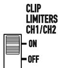
Clip Limiters (PLX 1802/2502/3102/3602 models only)
The amplifier has a clip limiter with an on-off switch. The limiter only responds to actual clipping, and automatically compensates for load and voltage variations. Clip limiting is generally recommended, especially to protect high frequency drivers.
- Set the switch UP (ON position) to use Clip Limiting.
- Set the switch DOWN (OFF position) to disable the clip limiter.
Low Frequency Filters (PLX 1802/2502/3102/3602 models only)
Each channel has independent filter selection of Full Range (infrasonic filter only), 33Hz low cut, 100Hz low cut, or 100Hz High Cut. This allows tailoring the amplifier performance to that of the loudspeakers, offering the best possible performance from the system. Proper filtering reduces distortion and prevents amplifier overload.
TOP / FULL / SUB Switch: Select the type of loudspeaker being driven by each channel.
- Set the switch to the left for driving "top" boxes; applies 100Hz low cut
- Set the switch to the middle position for "full range" loudspeakers.
- Set the switch to the rightmost position for driving subwoofer.
33 Hz (low cut) / FULL Switch: Unless the loudspeaker has extended low frequency capability, we recommend setting the filter to the 33 Hz setting. The filter should only be set to FULL (turned off) for driving subwoofoers. Check the loudspeaker's specifications and use the 33 Hz filter if the loudspeaker's low frequency capability does not extend below 33 Hz.
- Set to FULL when driving loudspeakers that have low frequency capability below 33Hz or in studio monitoring applications.
- Set to 33Hz for loudspeakers which are not rated for frequencies below 33Hz .
Input Configuration selector switch

Clip Limiter ON/OFF switch
Low Frequency filter selection switches for each channel

Low Frequency filter selection table
| Load | Top / Full / Sub Switch | 33 Hz / Full Switch |
| Subwoofer | Sub | Full or 33 Hz |
| Small Full Range (10" and smaller woofer) | Full | 33 Hz |
| Large Full Range (12" and larger woofer) | Full | Full or 33 Hz |
| Top Box | Top | Full |
| Studio Reference | Full | Full |
Inputs
Each channel has a balanced XLR (female) and 1/4-inch TRS input. The XLR and TRS connectors for each channel are wired in parallel and can be used for "daisy chaining" an input signal to additional amplifiers.
The input impedance is 20k ohm balanced or 10k ohm unbalanced. Both XLR and TRS inputs are connected with standard cables and can be changed quickly. Pinouts are marked on the rear panel. Do not attempt to connect more than one input signal to a given channel.
Balanced connections are recommended to reduce AC hum and interference, especially with long cable runs. Unbalanced connections may be suitable for short cables. The signal's source impedance should be less than 600 ohms.
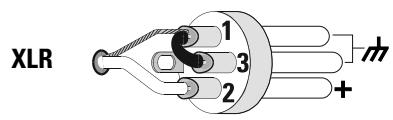
Input Pinouts
Balanced inputs: Connect to the plug as shown.

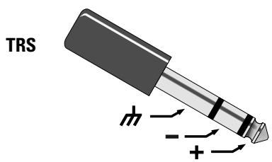
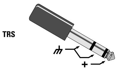
Unbalanced inputs: Connect to the plug as shown. If using an XLR connector, Pin 3 and pin 1 must be connected with a jumper as shown. If using a TRS connector, the ring and sleeve must be connected with a jumper. If a TS connector is used, the sleeve will provide the "jumper" when inserted into the input jack.

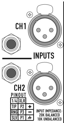
Input connectors and pinout chart (PLX1802 shown)
PLX 1104 and PLX 1804 models can parallel the input signal to both channels by using a jumper from one channel to the next:
-
Connect the input signal to either of Channel 1's input connectors.
-
Connect a jumper from Channel 1's unused connector to either of Channel 2's input connectors.

TRS to TRS jumper from Channel 1 to Channel 2
Outputs
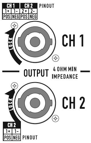
The PLX 1104 and PLX 1804 models are equipped with Speakon output connectors for each channel. PLX 1802, PLX 2502, PLX 3102, and PLX 3602 models are equipped with Speakon and binding post output connectors.
Wiring connections are shown on the back of the chassis. Carefully note the markings and maintain consistent loudspeaker polarity for optimum system performance.
Speakon Output Connectors
If making Speakon cables, be sure to connect the loudspeaker wiring as shown on the chassis. Channel 1's Speakon provides 4-wire (Ch 1 + Ch 2) connection; Channel 2's Speakon provides 2-wire (Ch 2 only) connection. Appendix A provides Speakon connection reference.
Stereo and Parallel Mode: Connect each loudspeaker to its own channel of the amplifier, as shown on the chassis label. The INPUT CONFIGURATION switch must be set for STEREO or PARALLEL mode.
Bridge Mode (PLX1802/2502/3102/3602 models only): Use Channel 1's Speakon for Bridge mode output connection. Bridge mode configures the channel pair to drive a single high-power loudspeaker load. The INPUT CONFIGURATION switch must be set for BRIDGE mode. Use only Channel 1's input and Gain control. Set Channel 2's Gain control at minimum.
PLX 1104 and PLX 1804 Output Connectors: Do not use less than 4 ohm impedance loads with PLX 1104 and PLX 1804 models.

Binding Post Connectors (PLX 1802/2502/3102/3602 models only)
Stereo and Parallel Mode: Connect each loudspeaker to its own channel of the amplifier, as shown on the chassis label. The INPUT CONFIGURATION switch must be set for STEREO or PARALLEL mode.
Bridge Mode: Bridge mode configures the channel pair to drive a single high-power loudspeaker load. The INPUT CONFIGURATION switch must be set for BRIDGE mode. Use only Channel 1's input and Gain control. Set Channel 2's Gain control at minimum.

OUTPUT TERMINAL SAFETY WARNING! Do not touch output terminals while amplifier power is on. Make all connections with amplifier turned off. Risk of hazardous energy!
PLX 1802, PLX 2502, PLX 3102, and PLX 3602 Output Connectors: Do not use less than 2 ohm impedance loads with these models.


Stereo & Parallel
8Ω
4Ω
2Ω√

Bridge
8Ω
4Ω

LED Indicators
The LED indicators can be used to monitor system operation and identify common problems.
POWER (PWR): BLUE
Normal indication:
- AC switch ON: LED will illuminate; on some models, LED will illuminate dimly during startup sequence.
If no indication:
- Check AC power cord and AC outlet.
- Confirm that AC switch is in ON position.
CLIP: RED
Normal indication:
- Illuminates whenever the amplifier is driven beyond full power. The resulting distortion corresponds to the brightness of the LED. Distortion that causes only brief flashing may not be audible.
- During muting, the red LED fully illuminates. This occurs during normal "On-Off" muting.
Abnormal indication:
- Bright red illumination while the amp is being used indicates either thermal muting or a shorted output.
- If the amplifier overheats, the fan will run at full speed, and operation should resume within one minute. Allow the fan to run, and make sure the amplifier ventilation is adequate.
- A shorted or overloaded output circuit will cause excessive Clip flashing and possible overheating.
- If distortion is audible without a Clip indication, the problem is either before or after the amplifier. Check for damaged speakers or overloaded signal source. The amplifier Gain control should be in the upper half of its range to prevent input overload.
SIGNAL (SIG), -10: GREEN
Normal indication:
- The SIG (signal) indicator illuminates when the output signal exceeds -35 dB, and the -10 (-10 dB) indicator illuminates when the signal exceeds -10 dB.
If no indication:
- Check Gain settings and increase gain if necessary. Check input connections and audio source for signal. If the Clip LED illuminates with little or no Signal indication, check the output wiring for shorts.
Abnormal indication:
- If the SIG or -10 LED illuminates with no signal input, there may be system oscillations or some other malfunction. Disconnect the load and fully reduce the gain. If the LED remains on, the amp may need servicing.
BRIDGE MONO (BR M) and PARALLEL (PAR) (PLX 1802/2502/3102/3602 models only):
- Each channel pair has a AMBER LED for Bridge Mode, and a AMBER LED for Parallel mode. These show how the rear panel INPUT CONFIGURATION switch is set (see Input Configuration Switch). In Stereo mode, both LEDs should be OFF. In bridge mode the BR M and PAR indicator will be illuminated. In parallel mode, the PAR indicator will be illuminated.
LED indicators on PLX 1104 and PLX 1804 models

LED indicators on PLX 1802, PLX 2502, PLX 3102, and PLX 3602 models

Gain Controls
Turn the GAIN controls clockwise to increase gain and counter clockwise to decrease gain.
The GAIN controls are marked in dB of attenuation. There are 21 detents for repeatable adjustments. The upper 14 steps are about 1 dB each, and settings should normally be made within this range. The range below - 14 dB should not be used for normal program levels, as the input headroom could be exceeded, but can be used for testing at reduced levels. At the minimum setting, the signal is completely cut off.

Note! The GAIN controls do not adjust the power of the amplifier. They adjust its sensitivity to input signals.
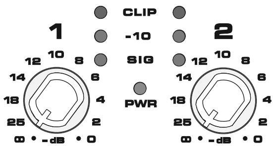
Gain controls and LED cluster on PLX 1104 and PLX 1804 models
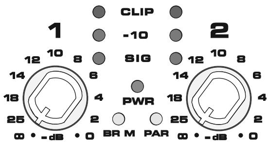
Gain controls and LED cluster on PLX 1802, PLX 2502, PLX 3102, and PLX 3603 models
Power Switch
Push in on the top of the rocker switch to apply AC mains power to the amplifier. Push in on the bottom of the rocker switch to turn the amplifier off.
When turned on, the blue PWR indicator LED and the red CLIP indicator LED will illuminate; after a few seconds the red CLIP indicator will extinguish.

Protection Systems
Both amplifier platforms are fully protected against adverse conditions, but their behavior and user adjustments are different.
PLX 1802/2502/3102/3602 models:
- Clip Limiting may be switched on the rear panel to prevent severe overdrive. This protects speakers and somewhat reduces the load on the amplifier.
- Internal current limits protect the output transistors against overloading. Peak limiting may occur at full output if using more than four 8-ohm speakers per channel, or if the speaker wiring is shorted. The red Clip LED will flash brightly, and the amplifier may sound distorted. If the amplifier is driven hard under these conditions, the current limit will be further reduced, causing an increase in distortion. If the amplifier appears to be losing power during peaks, check the speaker wiring and number of speakers. Using Clip Limiting will reduce this distortion, but for best results do not exceed the rated loading.
- If the amplifier stops completely for several seconds after a very loud signal, it may be overloading the AC service. This only occurs if the AC voltage sags more than 30% , and will be more likely if driving many speakers at once. Use short, heavy-gauge AC cables and do not plug too many amplifiers into a single outlet.
In Bridge Mono, the amplifier may shut down for several seconds if driven too hard into loads less than the rated 4-ohm minimum. - If the amplifier overheats due to prolonged overload or high external temperature, it will mute for about 30 seconds with the fan running at full speed for maximum cooling. Make sure the rear intake is getting a free flow of cool air.
PLX 1104/1804 models:
These models have completely automatic internal protection that maintains operation even under extreme conditions.
- Overdrive distortion will cause the red Clip LED to flash. If driven constantly into clipping, internal circuitry smoothly reduces the volume to minimize distortion and stress.
These models are rated for 4-ohm loads. Do not use more than two 8-ohm speakers per channel. Using too many speakers may trigger limiting and cause a loss of volume.
- Internal current limits protect the output transistors against overloading. Moderate overloading will trigger clip limiting, and smoothly reduce output level to prevent distortion. Severe overloading, such as driving the amplifier hard into a shorted speaker wire, may cause short, rapid muting. Check the speaker wiring for shorts if the amplifier "chatters".
- Overheating may occur due to prolonged overdrive or high external temperature. This will first trigger thermal limiting, reducing volume so that the amplifier remains below its thermal limit and keeps running. If input signals are still too high, the amplifier may eventually mute for about 30 seconds with the fan at full speed for maximum cooling. Make sure the rear intake is getting a free flow of cool air.
Specifications PLX 1104, PLX 1804
| PLX 1104 | PLX 1804 | ||
| OUTPUT POWER (Watts)(1) | |||
| 20 - 20k Hz, 0.05% THD, 8 ohms/Ch. | 310 | 550 | |
| 1k Hz, 0.1% THD (EIA), 8 ohms/Ch. | 325 | 600 | |
| 20 - 20k Hz, 0.05% THD, 4 ohms/Ch. | 500 | 800 | |
| 1k Hz, 0.1% THD (EIA), 4 ohms/Ch. | 550 | 900 | |
| DISTORTION, SMPTE-IM | 0.02% | 0.02% | |
| FREQUENCY RESPONSE | 20 - 20k Hz, ±0.5 dB, all models | ||
| SIGNAL to NOISE, unweighted, 20 - 20k Hz | -108 dB | -106 dB | |
| VOLTAGE GAIN | 32.5 dB | 34.9 dB | |
| INPUT SENSITIVITY, Vrmsfor rated power into 8 ohms | 1.18 (+3.7 dBu) | 1.20 (+3.8 dBu) | |
| OUTPUT CIRCUIT TYPE | AB | AB/H | |
| INPUT IMPEDANCE | 10k ohms unbalanced, 20k ohms balanced | ||
| DYNAMIC HEADROOM | 2 dB at 4 ohms | ||
| DAMPING FACTOR (8 ohms) | >200 | ||
| AMPLIFIER PROTECTION | Short circuit, open circuit, thermal, ultrasonic and RF protection. Stable into reactive or mismatched loads | ||
| COOLING | Continuously variable speed fan; back-to-front air flow through heat sink array | ||
| CONTROLS | Front: | AC POWER switch, Gain controls (each channel) 21 detents | |
| Back: | AC circuit breaker | ||
| LED INDICATORS | POWER (blue), SIGNAL (green x 2), -10 dB (green x 2), CLIP (red x 2) | ||
| CONNECTORS | Input: | 1/4-inch TRS and female XLR; 20k ohm balanced, 10k ohm unbalanced | |
| Output: | Speakon connectors: Ch 1, 4-wires (Ch 1 + Ch 2); Ch 2, 2-wires (Ch 2 only) | ||
| LOAD PROTECTION | Turn-on/turn-off muting, DC fault blocking, Clip limiting, Infrasonic filter (-3 dB at 5 Hz) | ||
| POWER REQUIREMENTS | Refer to rear panel serial number label. Configured at factory for 100, 120 or 220-240 VAC, 50- 60 Hz. | ||
| DIMENSIONS | 19.0" (48.3 cm) W, 3.5" (8.9 cm) H, 10.1" (25.7 cm) D (from front mounting rails, including rear support ears) | ||
| WEIGHT(1) | 13 pounds (5.9 kg) net; 18 pounds (8.2 kg) shipping | ||
(1) NOTE: Due to special construction to meet EN-6100, CE models may have 5-12% (0.5 dBw) less power and 1.2 lb (0.6 kg) more weight.
Specifications PLX 1802, PLX 2502, PLX 3102, PLX 3602
| PLX 1802 | PLX 2502 | PLX 3102 | PLX 3602 | |
| OUTPUT POWER (Watts)(1) | ||||
| 20 - 20k Hz, 0.05% THD, 8 ohms/Ch. | 320 | 425 | 550 | 725 |
| 1k Hz, 0.1% THD (EIA), 8 ohms/Ch. | 330 | 450 | 600 | 775 |
| 20 - 20k Hz, 0.05% THD, 4 ohms/Ch. | 525 | 675 | 900 | 1100 |
| 1k Hz, 0.1% THD (EIA), 4 ohms/Ch. | 575 | 750 | 1000 | 1250 |
| 1k Hz, 0.1% THD (EIA), 2 ohms/Ch. | 900 | 1250 | 1550 | 1800 |
| Bridge Mono, 20 - 20k Hz, 0.1% THD, 8 ohms | 1100 | 1400 | 1900 | 2500 |
| Bridge Mono, 1k Hz, 0.1% THD, 8 ohms | 1200 | 1500 | 2100 | 2600 |
| Bridge Mono, 1k Hz, 1.0% THD, 4 ohms | 1800 | 2500 | 3100 | 3600 |
DISTORTION, SMPTE-IM <0.02%, all models
FREQUENCY RESPONSE 20 - 20k Hz, ±0.5 dB, all models
SIGNAL to NOISE, unweighted, 20 - 20k Hz -107 dB -106 dB -107 dB
VOLTAGE GAIN 31.9 dB 34.0 dB 35.0 dB 35.9 dB
INPUT SENSITIVITY, Vrms for rated power into 8 ohms 1.28 (+4.4 dBu) 1.15 (+3.4 dBu) 1.23 (+4.0 dBu) 1.25 (+4.2 dBu)
OUTPUT CIRCUIT TYPE AB AB/H AB/H AB/H
INPUT IMPEDANCE 10k ohms unbalanced, 20k ohms balanced
DYNAMIC HEADROOM 2 dB at 4 ohms
DAMPING FACTOR (8 ohms) >500
AMPLIFIER PROTECTION Short circuit, open circuit, thermal, ultrasonic and RF protection. Stable into reactive or mismatched loads
COOLING Continuously variable speed fan; back-to-front air flow through heat sink array
CONTROLS Front: AC POWER switch, Gain controls (each channel) 21 detents
Back: Input Configuration Switch (Stereo, Parallel, Bridge), Clip Limiters (On/Off)
Subwoofer Switch (100 Hz Low Cut/Full Range/100 Hz High Cut, each channel)
LF Switch (33 Hz Low Cut/Full Range, 1 each channel)
LED INDICATORS POWER (blue), SIGNAL (green x 2), -10 dB (green x 2), CLIP (red x 2), BRDG (amber), PAR (amber)
CONNECTORS Input: 1/4-inch TRS and female XLR; 20k ohm balanced, 10k ohm unbalanced
Output: Speakon connectors: Ch 1, 4-wires (Ch 1 + Ch 2); Ch 2, 2-wires (Ch 2 only) Binding posts
LOAD PROTECTION Turn-on/turnoff muting, DC fault blocking, Clip limiting, infrasonic filter (-3 dB at 5 Hz).
POWER REQUIREMENTS Refer to rear panel serial number label. Configured at factory for 100, 120 or 220-240 VAC, 50-60 Hz.
DIMENSIONS 19.0" (48.3 cm) W, 3.5" (8.9 cm) H, 13.9" (35.3 cm) D (from front mounting rails, including rear support ears)
WEIGHT(1) 21 pounds (9.5 kg) net; 26 pounds (11.8 kg) shipping
(1) NOTE: Due to special construction to meet EN-6100, CE models may have 5-12% (0.5 dBw) less power and 1.2 lb (0.6 kg) more weight.
Appendix A: Speakon Wiring Reference


NOTE! Ensure proper polarity when connecting bridge mode output!
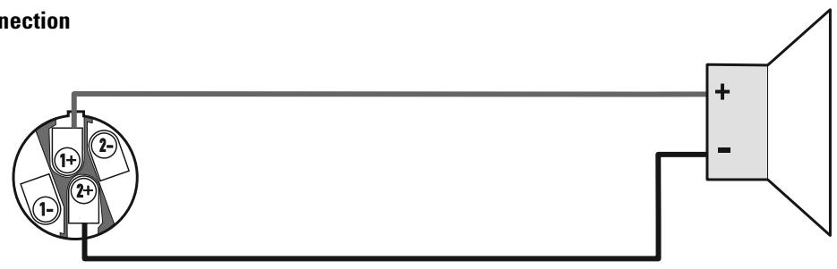
Bridge mode connection
Copyright 2006, QSC Audio Products, LLC
| Load | Top / Full / Sub Switch | 33 Hz / Full Switch |
| Subwoofer | Sub | Full or 33 Hz |
| Small Full Range (10" and smaller woofer) | Full | 33 Hz |
| Large Full Range (12" and larger woofer) | Full | Full or 33 Hz |
| Top Box | Top | Full |
| Studio Reference | Full | Full |
Entradas
Modelos PLX 1802/2502/3102/3602:
Copyright 2006, QSC Audio Products, LCC
| Load | Top / Full / Sub Switch | 33 Hz / Full Switch |
| Subwoofer | Sub | Full or 33 Hz |
| Small Full Range (10" and smaller woofer) | Full | 33 Hz |
| Large Full Range (12" and larger woofer) | Full | Full or 33 Hz |
| Top Box | Top | Full |
| Studio Reference | Full | Full |
Entres
Copyright 2006, QSC Audio Products, LLC
| Load | Top / Full / Sub Switch | 33 Hz / Full Switch |
| Subwoofer | Sub | Full or 33 Hz |
| Small Full Range (10" and smaller woofer) | Full | 33 Hz |
| Large Full Range (12" and larger woofer) | Full | Full or 33 Hz |
| Top Box | Top | Full |
| Studio Reference | Full | Full |
Eingänge
Speakon-Ausgangsanschlüsse
Modelle PLX 1802/2502/3102/3602:
Copyright 2006, QSC Audio Products, LLC
QSC®是QSC Audio Products, LLC的注册商标
后面板PLX1802/2502/3102/3602
| Load | Top / Full / Sub Switch | 33 Hz / Full Switch |
| Subwoofer | Sub | Full or 33 Hz |
| Small Full Range (10" and smaller woofer) | Full | 33 Hz |
| Large Full Range (12" and larger woofer) | Full | Full or 33 Hz |
| Top Box | Top | Full |
| Studio Reference | Full | Full |
输入端
How to Contact QSC Audio Products
QSC Audio Products, LLC
1675 MacArthur Boulevard
Costa Mesa, CA 92626-1468 USA
Telephone Numbers:

Main Number
Sales & Marketing
Customer Service
(714) 754-6175
(714) 957-7100 or toll free (USA only) (800) 854-4079
(714) 957-7150 or toll free (USA only) (800) 772-2834
Facsimile Numbers:

Sales & Marketing FAX
Customer Service FAX
(714) 754-6174
(714) 754-6173
World Wide Web:

www.qscaudio.com
E-mail:
info@qscaudio.com
service@qscaudio.com
- PLX Series Professional Audio Amplifiers
- User Manual
- Important Safety Precautions & Explanation of Symbols
- FCC INTERFERENCE STATEMENT
- Introduction
- Unpacking
- Front Panel
- Rear Panel PLX 1802, PLX 2502, PLX 3102, PLX 3602
- Rack Mounting
- Cooling
- Do not block the front or rear air vents!
- AC Mains Connection
- AC Mains Current Draw
- NOTE! Current draw shown is for 120 VAC line. For 230 VAC models, multiply values shown by 0.5.
- Input Configuration Switch (PLX 1802/2502/3102/3602 models only)
- Clip Limiters (PLX 1802/2502/3102/3602 models only)
- Low Frequency Filters (PLX 1802/2502/3102/3602 models only)
- Inputs
- Input Pinouts
- Outputs
- Speakon Output Connectors
- Binding Post Connectors (PLX 1802/2502/3102/3602 models only)
- LED Indicators
- POWER (PWR): BLUE
- Normal indication:
- If no indication:
- CLIP: RED
- Abnormal indication:
- SIGNAL (SIG), -10: GREEN
- BRIDGE MONO (BR M) and PARALLEL (PAR) (PLX 1802/2502/3102/3602 models only):
- Gain Controls
- Power Switch
- Protection Systems
- PLX 1802/2502/3102/3602 models:
- PLX 1104/1804 models:
- Appendix A: Speakon Wiring Reference
- Entradas
- Modelos PLX 1802/2502/3102/3602:
- Entres
- Eingänge
- Speakon-Ausgangsanschlüsse
- Modelle PLX 1802/2502/3102/3602:
- 后面板PLX1802/2502/3102/3602
- 输入端
Brand : QSC AUDIO
Model : PLX 1104
Category : Audio Amplifier