
CMX 2000V - Power amplifier QSC AUDIO - Free user manual and instructions
Find the device manual for free CMX 2000V QSC AUDIO in PDF.
| Product type | 2-channel professional power amplifier |
| Brand | QSC Audio |
| Model | CMX 2000V |
| Dimensions (H × W × D) | 133 mm × 483 mm × 400 mm |
| Net weight | 34 kg |
| Power supply | 100-120 V~ / 220-240 V~, 50-60 Hz |
| Typical consumption (1/8 power, 4 Ω) | 13.9 A (120 V~) / 7 A (230 V~) |
| Output power (stereo, 8 Ω, FTC) | 1050 W per channel |
| Output power (stereo, 4 Ω, FTC) | 1600 W per channel |
| Output power (bridge mono, 8 Ω, FTC) | 3200 W |
| Operating modes | Stereo, parallel inputs, bridge mono |
| Main features | Independent defeatable amplitude limiters, selectable low-frequency filter (30 Hz / 50 Hz / Off), protection against overheating and short circuits |
| Input connectors | Female XLR, 6.35 mm TRS, barrier strip (per channel) |
| Output connectors | Speakon™ NL4MD (2) and detachable terminal block |
| Indicators | Power (green), Signal (green), Limiter/clipping (red), Protection (yellow) |
| Cooling | Variable speed fan, airflow from rear to front |
| Maintenance and cleaning | Clean with a dry cloth. Do not block the ventilation openings. Provide a clearance of 152 mm at the rear. |
| Safety | Mandatory grounding. Do not expose to rain or moisture. Use only accessories specified by QSC. |
| Spare parts and repairability | Repairs should be carried out by qualified personnel. Limited 3-year warranty (United States). |
| General information | Robust amplifier in 3RU chassis. 3-stage class H output circuit. |
Frequently Asked Questions - CMX 2000V QSC AUDIO
User questions about CMX 2000V QSC AUDIO
0 question about this device. Answer the ones you know or ask your own.
Ask a new question about this device
Download the instructions for your Power amplifier in PDF format for free! Find your manual CMX 2000V - QSC AUDIO and take your electronic device back in hand. On this page are published all the documents necessary for the use of your device. CMX 2000V by QSC AUDIO.
USER MANUAL CMX 2000V QSC AUDIO
The lightning flash with the arrowhead symbol within an equilateral triangle is intended to alert the user to the presence of uninsulated "dangerous" voltage within the product's enclosure that may be of sufficient magnitude to constitute a risk of shock to humans.

The exclamation point within an equilateral triangle is intended to alert the user to the presence of important operation and maintenance (servicing) instructions in this manual.
- Read these instructions.
- Keep these instructions.
- Heed all warnings.
- Follow all instructions.

WARNING: To prevent fire or electric shock, do not expose this equipment to rain or moisture. Do not use this apparatus near water.
- Clean only with a dry cloth.
- Allow a minimum of 6" (152 mm) clearance behind cabinet for convection cooling. Keep anything that might restrict airflow from the rear of the enclosure (i.e. draperies, fabric, etc.). Do not block any ventilation opening. This product is a power amplifier that produces heat.
- Do not install near any heat sources such as radiators, heat registers, stoves, or other apparatus (including amplifiers) that produce heat.
- Do not defeat the safety purpose of the grounding-type plug on the three-pronged "Edison" style power cable. The grounding plug has two blades and a grounding prong. The third prong is provided for your safety. If the provided plug does not fit your outlet, consult an electrician for the replacement of the obsolete outlet. Do not cut off the grounding plug or use an adapter that breaks the grounding circuit. This apparatus must be properly grounded for your safety.
- Protect the power cord from being walked on or pinched, particularly plugs, convenience receptacles, and the point where they exit from the apparatus.
- The appliance coupler is the AC mains disconnect and should remain readily operable after installation.
- Use only attachments/accessories specified by QSC Audio Products, LLC.
- Use only with hardware, brackets, and components sold with the apparatus or by QSC Audio Products, LLC.
- Unplug the apparatus during lightning storms or when unused for long periods of time.
- Refer all servicing to qualified service personnel. Servicing is required when the apparatus has been damaged in any way, such as power supply cord or plug is damaged, liquid has been spilled or objects have fallen into the apparatus, the apparatus has been exposed to rain or moisture, does not operate normally or has been dropped.
- The appliance shall not be exposed to dripping or splashing and no objects filled with liquids, such as vases, shall be placed on the apparatus.
Warranty (USA only; other countries, see your dealer or distributor)
Disclaimer
QSC Audio Products, LLC is not liable for any damage to amplifiers, or any other equipment that is caused by negligence or improper installation and/or use of this loudspeaker product.
QSC Audio Products 3-Year Limited Warranty
QSC Audio Products, LLC ("QSC") guarantees its products to be free from defective material and / or workmanship for a period of three (3) years from date of sale, and will replace defective parts and repair malfunctioning products under this warranty when the defect occurs under normal installation and use - provided the unit is returned to our factory or one of our authorized service stations via prepaid transportation with a copy of proof of purchase (i.e., sales receipt). This warranty provides that the examination of the return product must indicate, in our judgment, a manufacturing defect. This warranty does not extend to any product which has been subjected to misuse, neglect, accident, improper installation, or where the date code has been removed or defaced. QSC shall not be liable for incidental and/or consequential damages. This warranty gives you specific legal rights. This limited warranty is freely transferable during the term of the warranty period. Customer may have additional rights, which vary from state to state.
In the event that this product was manufactured for export and sale outside of the United States or its territories, then this limited warranty shall not apply. Removal of the serial number on this product, or purchase of this product from an unauthorized dealer, will void this limited warranty. Periodically, this warranty is updated. To obtain the most recent version of QSC's warranty statement, please visit www.qscaudio.com. Contact us at 800-854-4079 or visit our web site at www.qscaudio.com.
Copyright 2010, QSC Audio Products, LLC
QSC is a registered trademark of QSC Audio Products, LLC
"QSC" and the QSC logo are registered with the U.S. Patent and Trademark Office
All trademarks are the property of their respective owners.
Introduction
Thank you for purchasing this QSC power amplifier. Please read the following directions to obtain the best results. The rugged fan-cooled, 2-channel, 3RU amplifier provides high-value performance and power in a strong, compact chassis.
Features
- Independent, user-defeatable clip limiters
- Fully selectable low-frequency filtering; choice of 30 or 50Hz roll-off
STEREO (dual channel), PARALLEL INPUT, or BRIDGE MONO operating modes
Balanced inputs - XLR, 1/4'' (6.3 mm) TRS, and barrier strip - Pluggable terminal block and Speakon™ outputs
21 detent attenuation knobs - Front panel LED indicators for power, signal, and clip
Attenuation control security plate
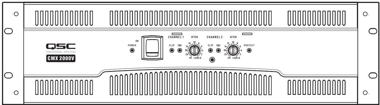
Figure 1
- Table 1 -
| STEREO Mode (Both channels driven) | |
| FTC: 20 Hz – 20 kHz @ 0.1% THD | |
| 8 ohms per channel | 1050 W |
| 4 ohms per channel | 1600 W |
| EIA: 1 kHz @ 1% THD | |
| 8 ohms per channel | 1100 W (0.1% THD) |
| 4 ohms per channel | 2000 W |
| 2 ohms per channel | 2500 W |
| 70V - Direct Drive | 2500 W |
| 100V - Direct Drive | 1000 W |
| BRIDGE MONO mode | |
| FTC: 20 Hz – 20 kHz @ 0.1% THD | |
| 8 ohms | 3200 W |
| EIA: 1 kHz @ 1% THD | |
| 8 ohm | 3600 W |
| 4 ohms | 5000 W (0.1% THD) |
| 140V - Direct Drive | 5000 W |
| 100V - Direct Drive | 3600 W |
Unpacking
Factory packed carton contains:
- CMX amplifier
- User's manual
- Adhesive rubber feet (for non-rack mount applications)
- Attenuation security plate
Rear rack ear mounting kit
IEC-type detachable power cord
Use the same type carton when shipping the amplifier.
Rack Mounting
Use four screws and washers to mount the amplifier to the equipment rack rails. To use the amplifier outside a rack, attach the self-adhesive rubber feet to the bottom. Use the rear rack ear support kit to support the rear of the amplifier for portable use. Refer to (Figure 2) for planning.
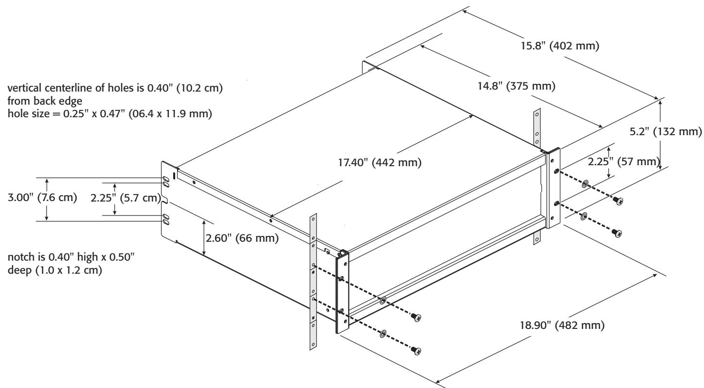
Figure 2
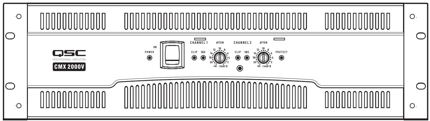
Front Panel (Figure 3)
- Cooling air exhaust vents
- Clip and Signal LEDs
- Power On LED
- Protect mode LED
- Power switch
- Security plate screw
- Attenuation controls
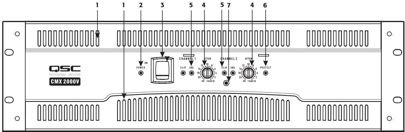
Figure 3
Back Panel
- Barrier strip input connectors
- Terminal block connector
- XLR input connectors
- AC circuit breakers
- TRS (1/4") input connectors
- Switch settings for PARALLEL INPUTS, STEREO, BRIDGE MONO
- Mode switches and settings
- Serial number label
- Cooling air inlet vents
- IEC power inlet (power cord connector)
- Speakon™ output connectors
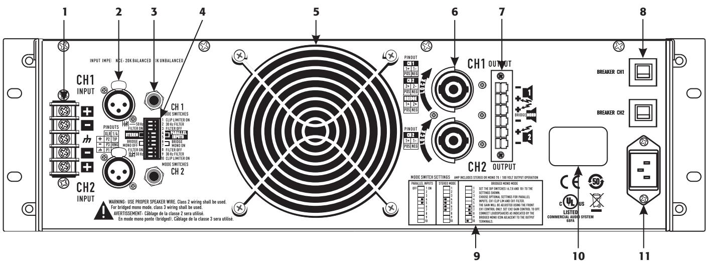
Figure 4
Features and Setup
Attenuation Control Security Plate
The Attenuation control security plate (Figure 5) provides protection against accidentally adjusting the Attenuation controls on the amplifier face.
Attach the plate, after making final adjustments to the Attenuation controls, by sliding the tabs into the two installation slots. Secure in place with the attachment screw.
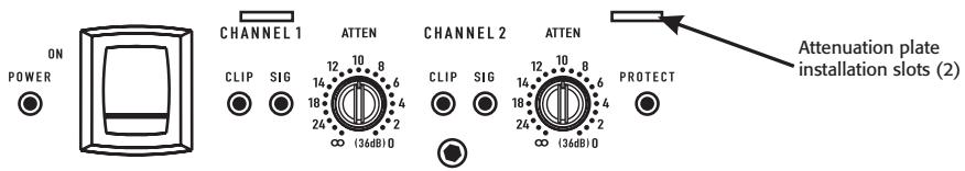
Attenuation plate not installed
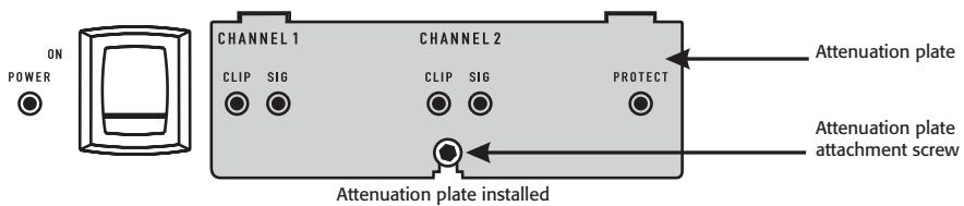
Figure 5
Setting the Mode Switches
The CMX 2000V has mode switches for STEREO, PARALLEL INPUTS, or BRIDGE MONO modes. Each channel has independent clip limiting and low frequency filtering.
Clip Limiter
What it is
When the audio signal drives the amp's output circuit beyond its power capability, it clips, flattening the peaks of the waveform. The clip limiter detects this and reduces the gain to minimize the amount of overdrive. To preserve as much of the program dynamics as possible, limiting reduces the average program level until peaks barely clip.
The limiter only responds to actual clipping, and automatically compensates for load and voltage variations. Each channel has its own clip limiter, and you can switch it on or off independently, as shown in (Figure 6).
When to use it (or not)
When driving full-range speakers, clip limiting reduces high-frequency distortion caused by bass overloads. It also protects higher frequency drivers from excess overdrive and harsh clipping harmonics.
When driving subwoofoers, some users let the amplifier clip without limiting because it gives extra "punch" to kick drums and similar sounds.

CAUSION: In bi-amplifier systems, excessive limiting will affect the frequency balance.

Figure 6
Input Low-Frequency Filter
What it is
The low-frequency (LF) filter rolls off signals below either 30Hz or 50Hz (Figure 9 and Figure 10). Each channel has a 12 dB per octave Low Frequency Filter to prevent cone over-excision, making more power available for the loudspeaker's rated frequency range. This reduces distortion and prevents amplifier overload.
The filter settings for each channel are controlled individually through the DIP switch settings shown in (Figure 7). When the filter is turned off (Figure 8), a 5Hz roll off protects against DC or deep sub-audio inputs.
When to use it (or not)
As a rule, your speakers will sound better with proper filtering. Unless you already have filtering in a preceding device, match the setting to the low frequency rating of your speakers. Vented (bass reflex, ported, etc.) speakers are especially sensitive to cone over-excursion at frequencies below their rated limit.
The 50Hz filter works well with most compact full-range speakers, and has a slight boost at 100Hz for greater fullness. The 30Hz filter is intended for subwoofoers and large full-range cabinets. The LF FILTER OFF position should be used only for applications such as studio playback monitoring, where you need to know if there are unwanted sub-audio signals present in your mix.

Figure 7
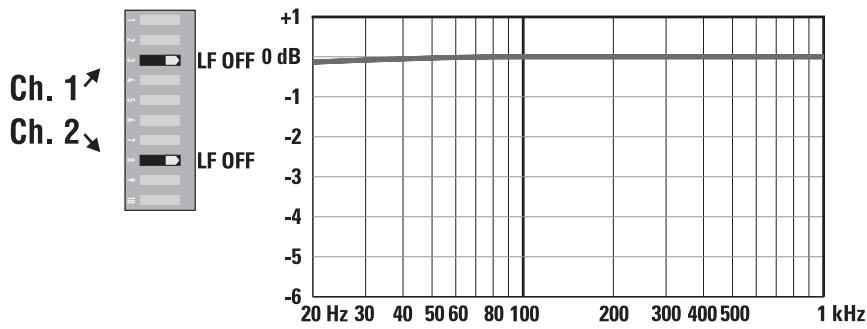
Figure 8
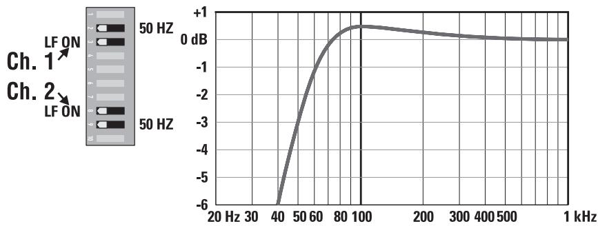
Figure 9

Figure 10
PARALLEL INPUTS Mode
What it is
The PARALLEL INPUTS switches let you operate the amplifier in a parallel mode, delivering the same signal to both channels without using a Y cable. Each channel drives its own speaker load, with independent gain, filtering, and clip limiting.
Set switch positions 4 and 5 to PARALLEL INPUTS to couple the inputs together (Figure 11). Turn the switches to STEREO for stereo, bi-amping, or other 2-channel modes.
In PARALLEL INPUTS mode, you can use the other set of input connectors to carry the signal to other amplifiers (Figure 12). This is often called a daisy-chain.
When to use it
Use the PARALLEL INPUTS mode when driving two speakers with one input signal. This maintains separate control of gain, filtering, and limiting.
Note: If you're using a balanced signal, use only balanced patch cables; even one unbalanced cable will unbalance the entire signal chain, possibly causing hum.
Note: Turn off the "Parallel Inputs" switches when feeding the amp two separate signals.

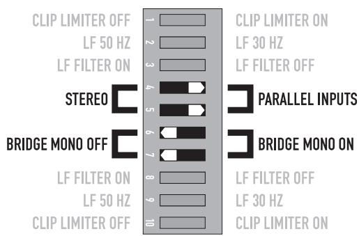
Figure 11
Figure 12
Bridge Mono Mode
What it is
Bridge mono mode combines the power of both amplifier channels into one speaker, resulting in twice the voltage swing, four times the peak power, and approximately three times the sustained power of a single channel. This mode uses Channel 1's input, attenuation control, input filter, and clip limiter; Channel 2's dip switch settings should be in the OFF positions, the Attenuation control should be at maximum attenuation (Figure 13 and Figure 14).
When to use it (or not)
Use Bridge mono to deliver the power of both channels to a single 8 or 4Ω load. Set switch positions 6 and 7 to BRIDGE MONO ON (Figure 13). Use Channel 1's inputs, and connect the speaker as shown in (Figure 15 and Figure 16).
BRIDGE MONO Precautions
This mode puts a high demand on the amplifier and speaker, Excessive clipping may cause protective muting or speaker damage. Be sure the speaker has a sufficient power rating.

WARNING: Output voltages greater than 100 volts RMS are present between the bridged terminals of the CMX 2000V. CLASS 3 wiring methods (NEC 1999), as specified in accordance with national and local codes, must be used to connect the speaker.

Channel 2 settings, switches 8, and 10 are set to off.
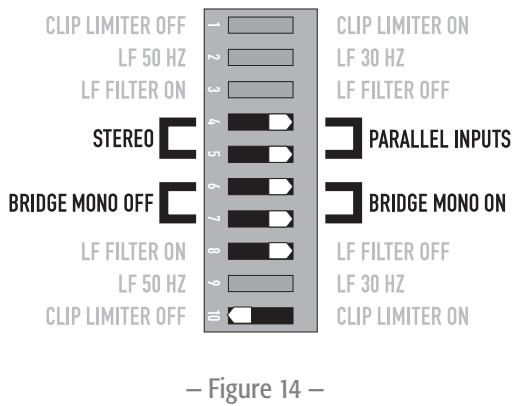
To patch the signal to additional amplifiers, use the PARALLEL INPUTS switch settings described under PARALLEL INPUTS Mode.


The Difference Between Modes
STEREO Mode
STEREO mode is the typical way of using the amplifier. Each channel is fully independent. Separate signals connect at the inputs, the attenuation knobs control their respective channels, and separate speakers connect to each output. The dip switches are set as shown in (Figure 17), a schematic illustration in (Figure 18).
Examples:
- Two-channel (stereo) playback.
- Two independent mono signals, such as main and monitor mixes.
- Bi-amped operation, with the low frequencies in Channel 1 and the highs in Channel 2.
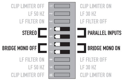
Figure 17

Figure 18
PARALLEL INPUTS Mβode
This mode is similar to the STEREO mode, except that the inputs for Channel 1 and Channel 2 are internally connected together. A signal into Channel 1 jack drives both channels directly (Figure 19). Use Channel 1 Input, do not connect different sources to both channels. Each channel's attenuation control still functions as usual, and each channel feeds its own speaker load. The dip switches are set as shown in (Figure 20).
In PARALLEL INPUTS mode, you can patch the input signal on to additional amplifiers by using any of the remaining input jacks. See Ch 2 in (Figure 19).
Example:
- One mono signal driving both channels, with independent attenuation control for each speaker system.
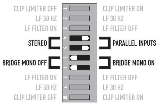
Figure 20
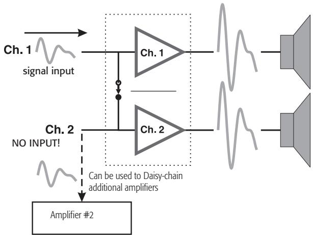
Figure 19
BRIDGE MONO Mode
This mode combines the full power capabilities of both channels into a single speaker system. The amplifier internally re-configures so that both channels operate as a unit. This delivers double the output voltage, resulting in four times the peak power and three times the sustained power into a single 8 or 4 ohm speaker load. The BRIDGE MONO mode section on page 9 describes the special speaker connection used. Refer to (Figure 21 through Figure 23).
Examples:
- Driving a single 8 ohm speaker with the combined 4 ohm power of both channels.
- Driving a single 4 ohm speaker with the combined 2 ohm power of both channels.
Precautions
- BRIDGE MONO mode makes it possible to drive thousands of watts into a single speaker. AC current consumption will usually be higher. Avoid excessive signal level, and make sure the wiring and speaker can handle the power.
- If the load is 4 ohms or less and prolonged overloads occur, the amplifier will probably mute for several seconds during peaks, and the circuit breaker may trip.
- Do not use 2 ohm loads.
See the additional BRIDGE MONO mode warnings on page 9.
Figure 21
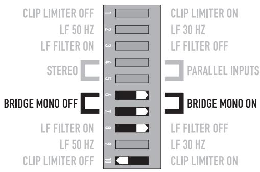
Set Channel 2 dip switches, 8 and 10, to off.
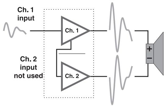
Figure 22

Figure 23
Distributed Constant Voltage Outputs
70 / 100 Volt Operation
The CMX 2000V can operate in 70 Volt or 100 Volt operation in STEREO mode or BRIDGE MONO mode. Please refer to the above section on BRIDGE MONO mode for proper setup and configuration. Refer to (Table 2) for the power outputs of these modes.
- Table 2 -
| STEREO Mode (Both Channels Driven) | |
| 70 Volt | 2500 W |
| 100 Volt | 1000 W |
| BRIDGE MONO mode | |
| 70 Volt | 5000 W |
| 100 Volt | 3600 W |
Connections
Inputs
Each channel has active balanced XLR, 14 (6.3 mm), and Barrier Strip inputs wired in parallel (Figure 24). The input impedance for balanced is 20k ohms, for unbalanced it is 10k ohms
Balanced connections are recommended to reduce AC hum and interference, especially with long cable runs. Unbalanced connections may be suitable for short cables. The signal's source impedance should be less than 600 ohms.
Balanced Inputs
Use the XLR or 1/4'' (6.3 mm) TRS input jacks, or the barrier strip. (Figure 24)
Unbalanced Inputs:
Connect the unused side (Pin 3) of the balanced input to ground (Pin 1), as shown in (Figure 25).
For STEREO operation, use the inputs for both Channel 1 and Channel 2. For PARALLEL INPUTS or BRIDGE MONO operation, use the Channel 1 input.
See the section on operating modes for more information. To patch the audio signal to other amplifiers (PARALLEL INPUTS and BRIDGE MONO modes only), see the instructions for using PARALLEL INPUTS on page 8 through page 11.
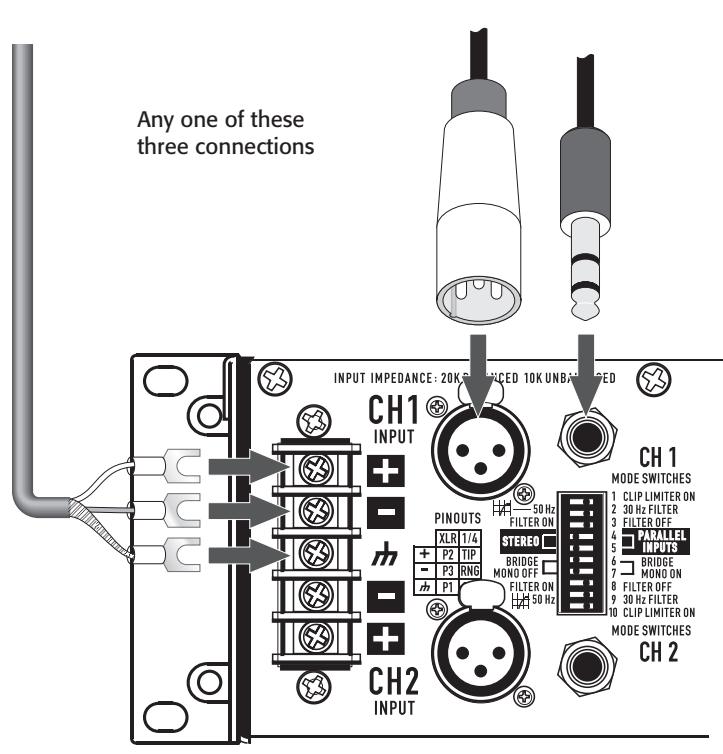
Figure 24
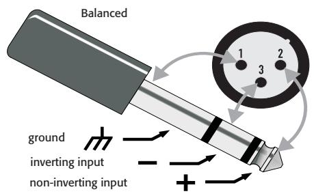
Figure 26
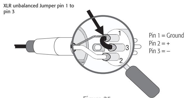
Figure 25
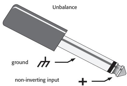
Figure 27
Speakon™ Outputs
CMX amplifiers offer a choice of output connections, with two NL4MD Speakon™ jacks and a terminal block connector. (Figure 28 through Figure 30)
The Speakon™ connector is designed specially for high-power speaker connections. It locks in place, prevents shock hazard, and assures the correct polarity.
Each channel accepts a normal two-wire cable. In addition, Channel 1 accepts a four-wire cable. Channel 1 Speakon™ jack has both Channel 1 and Channel 2 output signals (Figure 29), so it is especially useful for PARALLEL INPUTS, bi-amp, or BRIDGE MONO operation (see BRIDGE MONO operating precautions on page 9). Channel 2 Speakon™ carries only the output from Channel 2.
For easier insertion, use the newer-style NL4FC Speakon™ connectors with quick-lock thumb latches.
Speaker Cabling
Larger wire sizes and shorter lengths minimize both loss of power and degradation of damping factor. Do not place speaker cables next to input wiring.

WARNING: To prevent electric shock, do not operate the amplifier with any of the conductor of the speaker wire exposed.

Figure 28
Two channels, two Speakon™ connectors using two wires each. (STEREO, bi-amp, or PARALLEL INPUTS mode)
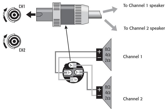
Figure 29
Two channels, one Speakon™ connector using four wires (STEREO, bi-amp, or PARALLEL INPUTS mode)
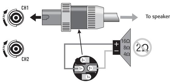
Figure 30
BRIDGE MONO MODE
Terminal Block Connector
The terminal block connector requires the following assembly.
- Strip the wires to 7 8mm
- Insert the wires into the male part of the connector according to the operating mode you are using. See (Figure 31).
- Use a flat-tip screwdriver to secure the wires. Tighten the screws to 6 in.-lbs.
- Insert the plug into the receptacle on the amplifier.
- Use a flat-tip screwdriver to secure the connector. Tighten the screws to 6 in.-lbs.
STEREO and PARALLEL INPUTS mode:
Wire as shown by loudspeaker symbols 1 and 2 on the back of the amplifier, and as shown by the solid wires in the diagram.
BRIDGE MONO mode:
Wire as shown by BRIDGE MONO loudspeaker symbol on the amplifier, and as shown by the dashed wires in (Figure 31).

Figure 31
- Table 3 -
| Terminal Block Connector Wiring | UL | IEC |
| Wire range | - | 6 mm² |
| Solid wire (AWG) | 28 – 10 | - |
| Stranded wire (AWG/mm²) | 28 – 10 | - |
| Torque (lb.-in.) | 6 | - |
| Wire strip length | 7 – 8 mm | - |
Operation
AC Power Switch
Before applying power, check all connections and turn the attenuation controls fully counter clockwise to maximum attenuation.
One second of muting is normal when the amplifier is turned on or off (Figure 32).
Attenuation Controls
Turn the Attenuation controls clockwise to decrease Attenuation and counterclockwise to increase Attenuation.
The Attenuation controls are marked in numeric increments from ∞ to 0 (clockwise) indicating the amount of attenuation. Settings should normally be made within the lower attenuation range. The range above 14 on the attenuation scale should not be used for normal program levels, as the input headroom could be exceeded, but can be used for testing at reduced gain levels. At the maximum attenuation setting (∞) , the signal is completely cut off (Figure 33).
The maximum Voltage Gain for the CMX 2000V is 31.6× (30dB)
LED Indicators
The green SIGNAL LED indicators light at approximately 0.1% of full power.
The red CLIP LED indicator flashes during overload (clipping).

CAUTION: Continuous operation at high power may trigger the thermal protection circuitry, shutting down the amplifier and fully illuminating the Protect indicator. Operation will resume after the amplifier has cooled down sufficiently. If both rear panel circuit breakers are tripped, the Protect indicator will not be illuminated. See the Troubleshooting on page
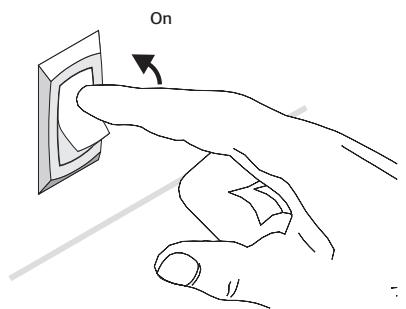
Figure 32
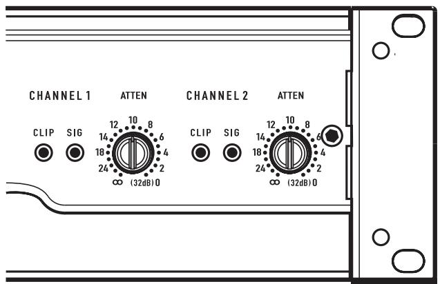
Figure 33
Operating Voltage
(AC Mains)
Make sure you connect the amplifier to the correct AC line voltage, as shown on the serial number label. Connecting to the wrong line voltage is dangerous and may damage the amplifier.
The power requirements are 100, 120, 230 VAC, 50-60 Hz

120 VAC
220-240 VAC
Figure 34
Fan Cooling
The fan speed varies automatically to maintain safe internal temperatures. Keep the front and rear vents clear to allow full air flow. Hot air exhausts out the front of the amplifier so it does not heat the interior of the rack. Make sure that plenty of cool air can enter the rack, especially if there are other units which exhaust hot air into it. See (Figure 35).
Safe Operating Levels
The amplifiers protective muting system guards against excessive internal temperatures. With normal ventilation and 4 to 8 ohm loads, the amplifier will handle any signal level including overdrive-but make sure that the speakers can handle the full power! However, lower load impedances and higher signal levels produce more internal heating. Into 2 ohm loads, frequent or prolonged clipping (indicated by constant flashing of the red CLIP LED) may trigger protective muting. Bridge mono mode doubles the output impedance of the amp; 4 ohms is the minimum load impedance. Heavy clipping may cause muting. If this happens, refer to the Troubleshooting, section.
Warm air exits the amplifier and rack.

Cool air enters the amplifier and rack.
Figure 35
Troubleshooting
Problem: No Sound
Indication: POWER indicator not lit
Check the AC plug. Also check the circuit breaker on the rear panel.
Confirm that the AC outlet works by plugging in another device. If too many amplifiers are used on one outlet, the building's circuit breaker may trip and shut off power.
An overload in Bridged Mono mode may cause the amplifier to click off for several seconds. Check the load impedance (4Ω minimum), or reduce signal level.
An amplifier which keeps shutting off may have a serious internal fault. Turn it off, remove AC power, and have the amplifier serviced by a qualified technician.
Indication: SIGNAL LED responding to signal level
If the green SIGNAL indicators are lighting normally, the fault is somewhere between the amp and the speaker. Check the speaker wiring for breaks. Try another speaker and cable.
Indication: SIGNAL LED not lit
If the green POWER indicator LED is lit and the fan is running, yet the signal LEDs indicate no signal, check the input. Make sure the signal source is operating and try another input cable. Connect the source to another channel or amplifier to confirm its operation.


Key

= lit
= blinking
=off
Indication: CLIP LED flashing
If the red CLIP indicator flashes when signal is applied, the amplifier output may be shorted. Check the speaker wiring for stray strands or breaks in the insulation.
Indication: CLIP LEDs bright and steady
The amplifier is in protective mating.
One second of muting is normal when the amp is turned on or off.
Overheating will cause protective muting. The fan will be running at full speed and the chassis will be hot to the touch; sound should resume within a minute as the amplifier cools to a safe operating temperature. Check for proper ventilation. If the fan isn't running at all, the amplifier requires servicing.
Overheating will cause protective muting. The fan will be running at full speed and the chassis will be hot to the touch; sound should resume within a minute as the amplifier cools to a safe operating temperature. Check for proper ventilation. If the fan isn't running at all, the amplifier requires servicing.
Problem: Distorted Sound
Indication: CLIP LED flashing
If the red CLIP indicator flashes before the signal indicator does, the load impedance is abnormally low or shorted. Unplug each speaker one-by-one at the amplifier. If the CLIP LED goes out when you disconnect a cable, that cable or speaker is shorted. Try another cable and speaker to locate the fault.
Indication: CLIP LED not flashing
This could be caused by a faulty speaker or loose connection. Check the wiring and try another speaker.
The signal source may be clipping. Keep the amplifier attenuation controls at mid point so that the source does not have to be overdriven.
Problem: No channel separation
Check the switch settings on the back of the amplifier. Make sure the "Parallel Input" and "BRIDGE MONO" switches are OFF in dual-channel, bi-amp, or stereo use where different signals go to each channel.
Make sure other equipment in the signal path, such as mixers, preamps, etc., are set for stereo, not mono.
Problem: Hum
Move cabling and signal sources to identify "hot spots" in the system. Cables with faulty shielding are a frequent entry point for hum.
Problem: Hiss
Unplug the amplifier input to confirm that the hiss is coming from the source or a device upstream; erratic or popping noises indicate an electronic fault in the offending unit.
To keep the normal noise floor low, operate the primary signal source at full level, without clipping, and avoid boosting the signal further between the source and the amplifier.
Problem: Squeals and feedback
Microphone feedback should be controlled with mixer controls. If noise continues to build up with zero mic gain, there is a serious fault in the signal processors or cables. Working in succession from the signal source towards the amplifier, check each device in the signal path by reducing its gain or unplugging it.


Key

= lit

= off
hking
Specifications
| CMX 2000V | |
| Stereo Mode (both channels driven) | |
| 8Ω / FTC 20 Hz - 20 kHz / 0.1% THD | 1050 W |
| 8Ω / EIA 1 KHZ / 0.1% THD | 1100 W |
| 4Ω / FTC 20 Hz - 20 KHZ / 0.1% THD | 1600 W |
| 4Ω / EIA 1 KHZ / 1% THD | 2000 W |
| 2Ω / EIA 1 KHZ / 1% THD | 2500 W |
| 70 V - Direct drive / EIA 1 kHz / 1% THD | 2500 W |
| 100 V - Direct drive / EIA 1 kHz / 1% THD | 1000 W |
| Bridge Mono Mode | |
| 8Ω / FTC 20 Hz - 20 kHz / 0.1%THD | 3200 W |
| 8Ω / EIA 1 kHz / 0.1%THD | 3600 W |
| 4Ω / EIA 1 kHz / 1%THD | 5000 W |
| 140 V - Direct drive / EIA 1 kHz / 1% THD | 5000 W |
| 100 V - Direct drive / EIA 1 kHz / 1% THD | 3600 W |
| Distortion (SMPTE-IM) | < 0.01% |
| Signal to Noise (20 Hz - 20 kHz) 8Ω | > -100 dB |
| Input Sensitivity 8Ω | 1.42 V (+5.3 dBu) |
| Voltage Gain (8Ω) | 36 dB |
| Output Circuitry | 3-tier Class H |
| Power Requirements | |
| Typical, 1/8 power, pink noise at 4Ω | |
| 120 VAC | 13.9 A |
| 230 VAC | 7 A |
| Severe, 1/3 power pink noise at 4Ω | |
| 120 VAC | 26.9 A |
| 230 VAC | 13.5 A |
| Frequency Response | 20 Hz - 20 kHz, +/- 1 dB dB -3 dB points: 5 Hz and 50 kHz (LF filter bypassed / 8Ω) |
| Damping Factor | > 300 at 8Ω |
| Input Impedance (Ω) | 10 kΩ unbalanced / 20 kΩ balanced |
| Input Clipping | 6.4 Vrms (+18 dBu) |
| Cooling | Continuously variable speed fan, back-to-front air flow |
| Connectors (each channel) | Input: Active balanced; barrier strip, XLR and 1/4" (6.3 mm) - TRS tip and XLR (pin 2 positive)Output: Detachable terminal block and Speakon™ |
| Controls | Front: AC Switch, Channel 1 and Channel 2 gain knobsRear: 10-position DIP switch |
| Indicators | Power-on: Green LED / Signal: Green LED (1 per channel) / Clip: Red LED (1 per channel) |
| Amplifier Protection | Stable into reactive or mismatched loads |
| Load Protection | On/off muting, triac crowbar on each channel |
| Dimensions (HWD) | 5.25" (3RU) x 19" x 15.9" (133 mm x 483 mm x 400 mm) |
| Weight - Net / Shipping | 75 lb (34 kg) / 87 lb (39.5 kg) |
Mailing Address:
QSC Audio Products, LLC
1675 MacArthur Boulevard
Costa Mesa, CA 92626-1468 USA
Telephone Numbers:
Main Number: (714) 754-6175
Sales & Marketing: (714) 957-7100 or toll free (USA only) (800) 854-4079
Customer Service: (714) 957-7150 or toll free (USA only) (800) 772-2834
Facsimile Numbers:
Sales & Marketing FAX: (714) 754-6174
Customer Service FAX: (714) 754-6173
World Wide Web:
www.qscaudio.com
E-mail:
info@qscaudio.com
service@qscaudio.com
Copyright 2010, QSC Audio Products, LLC
Mode Bridge Mono (Mono pont)
Définition
Mode BRIDGE MONO (Mono pont)
QSC Audio Products, LLC
1675 MacArthur Boulevard
service@qscaudio.com
Copyright 2010, QSC Audio Products, LLC
QSC Audio Products, LLC
1675 MacArthur Boulevard
Costa Mesa, CA 92626-1468 USA
Telefonnummern:
service@qscaudio.com
CMX2000V放大器
重要的安全注意事项和符号说明
警告!

© 版权所有 2010, QSC Audio Products, LLC
QSC是QSC Audio Products,LLC的注册商标

= lit
= blinking
=off
指示:削波LED指示灯闪烁
QSC Audio Products, LLC
1675 MacArthur Boulevard
Costa Mesa, CA 92626-1468 USA
电话:
总机:(714)754-6175
service@qscaudio.com
Amplificador CMX 2000V

Copyright 2010, QSC Audio Products, LLC
QSC es unamarcacommercial registrada de QSC Audio Products, LLC
QSC Audio Products, LLC
1675 MacArthur Boulevard
service@qscaudio.com
- Warranty (USA only; other countries, see your dealer or distributor)
- Disclaimer
- QSC Audio Products 3-Year Limited Warranty
- Introduction
- Features
- Unpacking
- Rack Mounting
- Front Panel (Figure 3)
- Back Panel
- Features and Setup
- Attenuation Control Security Plate
- Setting the Mode Switches
- Clip Limiter
- What it is
- When to use it (or not)
- Input Low-Frequency Filter
- PARALLEL INPUTS Mode
- When to use it
- Bridge Mono Mode
- BRIDGE MONO Precautions
- The Difference Between Modes
- STEREO Mode
- Examples:
- PARALLEL INPUTS Mβode
- Example:
- Precautions
- Distributed Constant Voltage Outputs
- / 100 Volt Operation
- Connections
- Inputs
- Balanced Inputs
- Unbalanced Inputs:
- Speakon™ Outputs
- Speaker Cabling
- Terminal Block Connector
- STEREO and PARALLEL INPUTS mode:
- BRIDGE MONO mode:
- Operation
- AC Power Switch
- Attenuation Controls
- LED Indicators
- Operating Voltage
- (AC Mains)
- Fan Cooling
- Safe Operating Levels
- Troubleshooting
- Indication: CLIP LED flashing
- Indication: CLIP LEDs bright and steady
- Problem: Distorted Sound
- Indication: CLIP LED not flashing
- Problem: No channel separation
- Problem: Hum
- Problem: Hiss
- Problem: Squeals and feedback
- Key
- Mailing Address:
- Telephone Numbers:
- Facsimile Numbers:
- World Wide Web:
- E-mail:
- Mode Bridge Mono (Mono pont)
- Définition
- Telefonnummern:
- 重要的安全注意事项和符号说明
- 警告!
Brand : QSC AUDIO
Model : CMX 2000V
Category : Power amplifier