
RMX 1850HD - Power amplifier QSC AUDIO - Free user manual and instructions
Find the device manual for free RMX 1850HD QSC AUDIO in PDF.

| Brand | QSC Audio |
| Model | RMX 1850HD |
| Product type | 2-channel power amplifier |
| Rack format | 2U (2 rack spaces) |
| Cooling | Variable-speed fan, hot air exhaust from front |
| Protection | Thermal (mute on overheat) and mains circuit breaker |
| LED indicators | Power (green), Signal (yellow), Clip (red) per channel |
| Audio inputs | 2 x XLR (balanced), 2 x 1/4" TRS (balanced), barrier strip |
| Audio outputs | 2 x Speakon NL4 (channel 1+2 and channel 2), 2 pairs of binding posts |
| Input impedance | 20 kΩ balanced, 10 kΩ unbalanced |
| Built-in functions | Independent per-channel clip limiters, switchable high-pass filters at 30 Hz or 50 Hz, stereo, parallel and bridged modes |
| Power supply | Alternating current (AC) according to voltage on serial label |
| Power consumption | Built-in circuit breaker, overload protection |
| Maintenance and cleaning | Clean with dry cloth only; do not block ventilation openings |
| Maximum ambient temperature | 50 °C |
| Safety | Grounding mandatory; do not expose to rain or moisture; do not open enclosure (no user-serviceable parts) |
| Spare parts and repairability | All repairs to qualified technician; 3-year warranty on parts and labor (conditions: normal use, return with proof of purchase) |
| Supplied accessories | Rack mounting screws and washers (4 pieces) |
| Intended use | Professional sound reinforcement, PA systems, stage and installed applications |
| Country of origin | United States (brand QSC Audio Products, Inc.) |
Frequently Asked Questions - RMX 1850HD QSC AUDIO
User questions about RMX 1850HD QSC AUDIO
0 question about this device. Answer the ones you know or ask your own.
Ask a new question about this device
Download the instructions for your Power amplifier in PDF format for free! Find your manual RMX 1850HD - QSC AUDIO and take your electronic device back in hand. On this page are published all the documents necessary for the use of your device. RMX 1850HD by QSC AUDIO.
USER MANUAL RMX 1850HD QSC AUDIO
Explanation of graphical symbols
The lightning flash with arrowhead symbol, within an equilateral triangle, is intended to alert the user to the presence of uninsulated "dangerous voltage" within the product's enclosure that may be of sufficient magnitude to constitute a risk of electric shock to humans.
The exclamation point within an equilateral triangle is intended to alert the users to the presence of important operating and maintenance (servicing) instructions in the literature accompanying the product.
CAUTION: To reduce the risk of electric shock, do not remove the cover. No user-serviceable parts inside. Refer servicing to qualified service personnel.
WARNING: To prevent fire or electric shock, do not expose this equipment to rain or moisture.
ATTENTION!
RISQUE DE CHOC ELECTRIQUE NE PAS OUVRIR
Explanation of graphical symbols 2
FEATURES & SETUP 8-13
CHARACTERISTIQUES ET LEUR UTILISATION
What are the differences among Stereo, Parallel Input, and Bridge
Mono modes? 12
Binding post outputs 17
Borns à écrou
Anschlussklemmen
Safe operating levels 19
Sound reinforcement 20
Sonorisation
Beschallung
Sonido en vivo
Instrument amplification 21
TROUBLESHOOTING 22-26
DéPANNAGE
FEHLERBEHEBUNG
BUSQUEDA DE AVERIAS
Problem: no sound 22
Problem: squeals and feedback 26
INFORMATIONS DE GARANTIE
ADDRESS & TELEPHONE INFORMATION 30
Copyright 1999, 2001 QSC Audio Products, Inc.
QSC® is a registered trademark of QSC Audio Products, Inc.
"QSC" and the QSC logo are registered with the U.S. Patent and Trademark Office.
All other trademarks are the property of their respective owners.
TD-000085-00 Rev. D
| Model | Power, 8 ohm/ch 1 kHz, 0.1% THD | Power, 4 ohm/ch 1 kHz, 0.1% THD | Power, 2 ohm/ch 1 kHz, 1% THD |
| RMX 850 | 200 W | 300 W | 430 W |
| RMX 1450 | 280 W | 450 W | 700 W |
| RMX 1850HD | 360 W | 600 W | 900 W |
| RMX 2450 | 500 W | 750 W | 1200 W |
The RMX Series Amplifiers.
These rugged fan-cooled, 2-channel, 2-RU amps provide high-value performance and power in a strong, compact chassis. The series comprises four models: the RMX 850, RMX 1450, RMX 1850HD, and RMX 2450.
The HD designation on the RMX 1850HD designates this model as "heavy duty". The RMX 1850HD is superior to all other RMX models for driving 2 ohm loads for extended periods. The RMX 1850HD is perfectly suited for subwoofer-type applications.
Features
- Independent, user-defeatable clip limiters
- Fully selectable low-frequency filtering; choice of 30 or 50Hz roll-off
- Stereo (dual-channel), parallel-input, or bridged mono operating modes
Balanced inputs—XLR, 1/4 (6.3 mm) TRS, and barrier strip - Binding post and Neutrik Speakon™ outputs
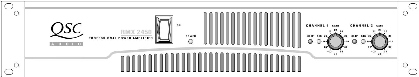
- Front panel LED indicators for signal and clip
- Power switch
- POWER indicator LED
- Cooling vents
- Gain control (Channel 1)
- Gain control (Channel 2)
- CLIP and SIGNAL indicator LEDs, both channels
Panneau avant
- Barrier strip input
- XLR inputs, Channels 1 and 2
- Configuration switch
- Configuration switch chart
- TRS inputs, Channels 1 and 2
- Speakon output, Channel 1 plus Channel 2
- Speakon output, Channel 2
- Binding post outputs, Channels 1 and 2
- Fan
- Serial number label
- IEC connector for AC power cable
- Circuit breaker
Panneau arrête
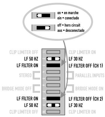
When the audio signal drives the amp's output circuit beyond its power capability, it clips, flattening the peaks of the waveform. The clip limiter detects this and reduces the gain to minimize the amount of overdrive. To preserve as much of the program dynamics as possible, limiting reduces the average program level until peaks barely clip.
Each channel has its own clip limiter, and you can switch it on or off independently, as shown at left.
WHEN TO USE IT (OR NOT)
When driving full-range speakers, clip limiting reduces high frequency distortion caused by bass overloads. It also protects higher frequency drivers from excess overdrive and harsh clipping harmonics.
When driving subwoofoers, some users let the amplifier clip without limiting because it gives extra "punch" to kick drums and similar sounds.
CAUTION: In bi-amp systems, excessive limiting will affect the frequency balance.
CHARACTERISTIQUES ET LEUR UTILISATION
= NOT APPLICABLE NON APPLICABLE NICTHT ANWENDBAR NO APPLICABLE
FEATURES & SETUP
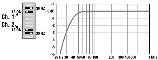
Input filter
WHAT IT IS
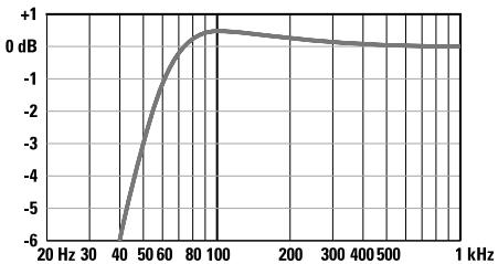
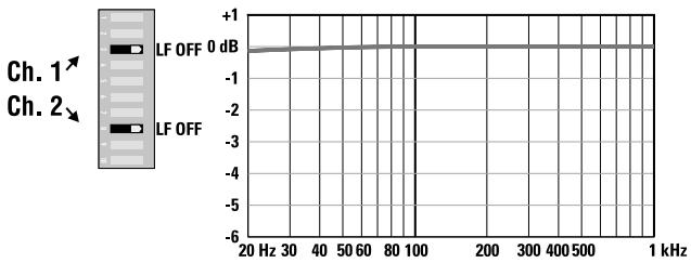
The low-frequency (LF) filter rolls off signals below either 30Hz or 50Hz . This improves bass performance by limiting sub-audio cone motion, making more power available for the speakers' rated frequency range.
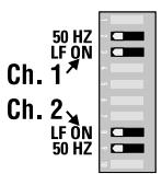
The filter settings for each channel are controlled individually through the DIP switch settings shown. When the filter is turned off, a 5 Hz rolloff protects against DC or deep sub-audio inputs.
WHEN TO USE IT (OR NOT)
As a rule, your speakers will sound better with proper filtering. Unless you already have filtering in a preceding device, match the setting to the low frequency rating of your speakers. Vented (bass reflex, ported, etc.) speakers are especially sensitive to cone over-excursion at frequencies below their rated limit.
The 50 Hz filter works well with most compact full-range speakers, and has a slight boost at 100 Hz for greater fullness. The 30 Hz filter is intended for subwoofoers and large full-range cabinets. The "off" position should be used only for applications such as studio playback monitoring, where you need to know if there are unwanted sub-audio signals present in your mix.
CHARACTERISTIQUES ET LEUR UTILISATION
Filtres d'entrée
DESCRIPTION
Patching the input signal to additional amps
FEATURES & SETUP
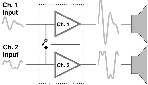
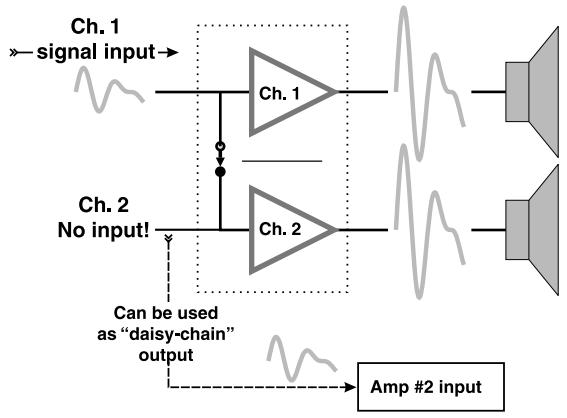
Parallel input mode
WHAT IT IS
The "Parallel Input" switches let you operate the amplifier in parallel mode, delivering the same signal to both channels without using a Y-cable. Each channel drives its own speaker load, with independent gain, filtering, and clip limiting.
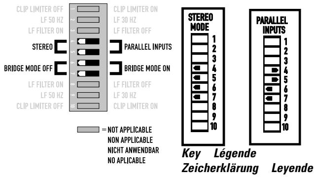
Set switch positions 4 and 5 "ON" to couple the inputs together. Turn the switches off for stereo, bi-amping, or other 2-channel modes.
With the inputs in parallel, you can use the other set of input connectors to carry the signal to other amps. This is often called a "daisy-chain."
WHEN TO USE IT
Parallel the inputs when driving two speakers with one input signal (parallel mode) while keeping separate control of both channels' gain, filtering, and limiting. Use them in bridged mono mode to patch the signal to additional amplifiers through the extra input jacks. See page 12 for an explanation of amp operating modes.
NOTE: If you're using a balanced signal, use only balanced patch cables; even one unbalanced cable will unbalance the entire signal chain, possibly causing hum.
NOTE: Turn off the "Parallel Inputs" switches when feeding the amp two separate signals.
CHARACTERISTIQUES ET LEUR UTILISATION
To patch the signal to additional amplifiers, use the parallel input switches described on page 10.
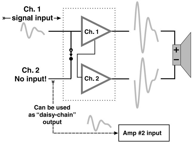
Bridged mono mode combines the power of both amp channels into one speaker, resulting in twice the
voltage swing, four times the peak power, and approximately three times the sustained power of a single channel. This mode uses Channel 1: input, gain control, input filter, and clip limiter; Channel 2's should not be used.
WHEN TO USE IT (OR NOT)
Use bridged mono to deliver the power of both channels to a single 8- or 4-ohm load. Set switch positions 6 and 7 to "BRIDGE MONO ON." Use Channel 1's inputs, and connect the speaker as shown.
BRIDGED-MONO PRECAUTIONS:
This mode puts a high demand on the amplifier and speaker. Excessive clipping may cause protective muting or speaker damage. Be sure the speaker has a sufficient power rating.
Output voltages greater than 100 volts rms are available between the bridged terminals of the RMX 2450. CLASS 3 wiring methods (NEC 1999), as specified in accordance with national and local codes, must be used to connect the speaker.
CHARACTERISTIQUES
ET LEUR UTILISATION
Mode ponté mono
DESCRIPTION
Stereo, bi-amp, 2-channel
Parallel
FEATURES & SETUP
What are the differences among Stereo, Parallel Input, and Bridge Mono modes?
STEREO MODE
This is the "normal" way of using the amplifier, in which each channel is fully independent. Separate signals connect at the inputs, the gain knobs control their respective channels, and separate speakers connect to each output.
Examples:
- Two-channel (stereo) playback.
- Two independent mono signals, such as main and monitor mixes.
- Bi-amped operation, with the low frequencies in Channel 1 and the highs in Channel 2.
PARALLEL INPUT MODE
This mode is just like Stereo mode, except that the inputs for Channel 1 and Channel 2 are internally connected together. A signal into any input jack will therefore drive both channels directly. Each channel's gain control still functions as usual, and each channel feeds its own speaker load.
You can patch the input signal on to additional amplifiers by using any of the remaining input jacks.
Example:
- One mono signal driving both channels, with independent gain control for each speaker system.
CHARACTERISTIQUES ET LEUR UTILISATION
Bridge mono with parallel switches engaged

FEATURES & SETUP
BRIDGE MONO MODE
This mode combines the full power capabilities of both channels into a single speaker system. The amplifier internally re-configures so that both channels operate as a unit. This delivers double the output voltage, resulting in four times the peak power and three times the sustained power into a single 8- or 4-ohm speaker load. The Bridge Mono mode section on page 11 describes the special speaker connection used.
Examples:
- Driving a single 8-ohm speaker with the combined 4-ohm power of both channels.
- Driving a single 4-ohm speaker with the combined 2-ohm power of both channels.
Precautions:
- Bridge Mono mode makes it possible to drive thousands of watts into a single speaker. AC current consumption will usually be higher. Avoid excessive signal level, and make sure the wiring and speaker can handle the power.
- If the load is 4 ohms or less and prolonged overloads occur, the amplifier will probably mute for several seconds during peaks, and the circuit breaker may trip.
- Do not use 2-ohm loads.
SEE THE ADDITIONAL BRIDGE MONO MODE WARNINGS ON PAGE 11.
CHARACTERISTIQUES ET LEUR UTILISATION
MODE PONTÉ MONO
Rack mounting of the amplifier is optional.
Use four screws and washers when mounting the amplifier to the front rack rails.
Support the amp at the rear also, especially in mobile and touring use; rear rack mounting ear kits are available from QSC's technical services department or by special order from your dealer or distributor.
INSTALLATION
XLR input pinout (unbalanced)
- pin 2
jumper pin1 to pin 3
力 pin1
CONNECTIONS Inputs
Each channel has active balanced XLR and 14 -inch (6.3 mm) inputs wired in parallel. The input impedance is 20 KΩ balanced, 10 KΩ unbalanced.
Balanced signals are less prone to AC hum, but unbalanced signals can be suitable for short cable runs. The signal source's output impedance should be less than 600Ω to avoid high frequency loss in long cables.
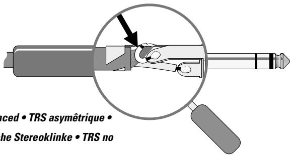
Balanced inputs: Use the XLR or 1/4 -inch (6.3 mm) TRS input jacks, or the barrier strip.
Unbalanced inputs: Connect the unused side of the balanced input to ground, as shown below left. A tip-sleeve 14 -inch (6.3 mm) connector will correctly terminate the unused side of the input without modification.
For two-channel (stereo) operation, use the inputs for both Channel 1 and Channel 2; for parallel or bridged mono operation, use the Channel 1 input. See the section on operating modes for more explanation. To patch the audio signal to other amps (parallel and bridged modes only), see the instructions for using parallel inputs on page 9.
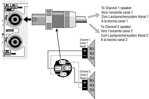
2 channels/canals/Kanäle/canals & 1 Speakon
(Stereo, bi-amp, or parallel mode; Modes stéreo, bi-amp ou parallele; Stereo-, Bi-Amp- oder Parallelbetrieb; Modos estéreo, bi-amp o parallelo)
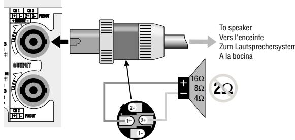
Bridged mono · Mono ponté · Monobrückenbetrieb · Mono puente
CONNECTIONS
Speakon™ Outputs
The RMX amplifier offers a choice of output connections, with two Neutrik NL4MD Speakon jacks and two pairs of "touchproof" binding posts.
The Speakon connector is designed specially for high-power speaker connections. It locks in place, prevents shock hazard, and assures the correct polarity.
The upper Speakon jack has both Channel 1 and Channel 2 outputs, so it is especially useful for parallel, bitamp, or bridged mono operation (see bridged mono operating precautions on page 11). The other Speakon carries only Channel 2's output. See the illustrations at left.
For easier insertion, use the newer-style NL4FC Speakon connectors with quicklock thumb latches.
SPEAKER CABLING
Larger wire sizes and shorter lengths minimize both loss of power and degradation of damping factor. Do not place speaker cables next to input wiring.
WARNING: To prevent electric shock, do not operate the amplifier with any of the conductor portion of the speaker wire exposed.
CONNEXIONS
Sorties Speakon™
CONNECTIONS Binding post outputs
- Strip back insulation not more than 13mm (1 / 2 inch).
- Insert wire fully so that none of the conductor is exposed; tighten barrel (use coin if necessary).
- Non-European models only.
- Spade lugs must have insulated barrels to prevent electric shock.
WARNING: To prevent electric shock, do not operate the amplifier with any of the conductor portion of the speaker wire exposed.
Connections for stereo and parallel operations
Connections for bridged mono operation. See bridged mono operating precautions on page 11.
SPEAKER CABLING
Larger wire sizes and shorter lengths minimize both loss of power and degradation of damping factor. Do not place speaker cables next to input wiring.
Operating voltage (AC mains)
Make sure you connect the amplifier to the correct AC line voltage, which is shown on the serial number label. Connecting to the wrong line voltage is dangerous and may damage the amplifier.
Before applying power, check all connections and turn down the gain controls.
One second of muting is normal when the amp is turned on or off.
Gain controls
The actual voltage gain of the amplifier is shown in dB.
LED indicators
The yellow SIGNAL LED indicators light at approximately 0.1% of full power.
The red CLIP LED indicator flashes during overload (clipping).
If the amplifier's protection circuitry triggers protective muting, the
SIGNAL and CLIP LEDs will not light. If this occurs during use, see the Troubleshooting section of this manual.
UTILISATION
The fan speed varies automatically to maintain safe internal temperatures. Keep the front and rear vents clear to allow full air flow.
Hot air exhausts out the front of the amp so it does not heat the interior of the rack. Make sure that plenty of cool air can enter the rack, especially if there are other units which exhaust hot air into it.
Safe operating levels
The amp's protective muting system guards against excessive internal temperatures. With normal ventilation and 4- to 8-ohm loads, the amplifier will handle any signal level including overdrive—but make sure that the speakers can handle the full power! However, lower load impedances and higher signal levels produce more internal heating. Into 2-ohm loads, frequent or prolonged clipping (indicated by constant flashing of the red CLIP LED) may trigger protective muting.
Bridged mono mode doubles the output impedance of the amp; 4 ohms is the minimum load impedance. Heavy clipping may cause muting. If this happens, see Troubleshooting, page 23.
UTILISATION
Ventilation
Instrument amplification
APPLICATIONS
Amplification
d'instrument
ANWENDUNGS-
BEISPIELE
INDICATION: POWER INDICATOR NOT LIT
- Check the AC plug. Also check the circuit breaker on the rear panel.
- Confirm that the AC outlet works by plugging in another device. If too many amplifiers are used on one outlet, the building's circuit breaker may trip and shut off power.
- An overload in bridged mono mode may cause the amplifier to click off for several seconds. Check the load impedance (4 ohms minimum), or reduce signal level.
- An amplifier which keeps shutting off may have a serious internal fault. Turn it off, remove AC power, and have the amplifier serviced by a qualified technician.
DÉPANNAGE
No sound (continued)
INDICATION: SIGNAL LED NOT LIT
- If the green POWER indicator LED is lit and the fan is running, yet the signal LEDs indicate no signal, check the input. Make sure the signal source is operating and try another input cable. Connect the source to another channel or amplifier to confirm its operation.
Overheating will cause protective muting. The fan will be running at full speed and the chassis will be hot to the touch; sound should resume within a minute as the amplifier cools to a safe operating temperature. Check for proper ventilation. If the fan isn't running at all, the amplifier requires servicing.
DÉPANNAGE
Pas de son (suite)
INDICATION: DEL SIGNAL ÉTEINTS CHECK
The amplifier is in protective muting.
One second of muting is normal when the amp is turned on or off.
Overheating will cause protective muting. The fan will be running at full speed and the chassis will be hot to the touch; sound should resume within a minute as the amplifier cools to a safe operating temperature. Check for proper ventilation. If the fan isn't running at all, the amplifier requires servicing.
DÉPANNAGE
INDICATION:CLIP LED FLASHING
- If the red CLIP indicator flashes before the signal indicator does, the load impedance is abnormally low or shorted. Unplug each speaker one-by-one at the amplifier. If the CLIP LED goes out when you disconnect a cable, that cable or speaker is shorted. Try another cable and speaker to locate the fault.
> INDICATION:CLIP INDICATOR NOT FLASHING
- This could be caused by a faulty speaker or loose connection. Check the wiring and try another speaker.
- The signal source may be clipping. Keep the amplifier gain controls at least halfway up so that the source does not have to be overdriven.
Problem: no channel separation
- Check the switch settings on the back of the amplifier. Make sure the "Parallel Input" and "Bridge Mode" switches are OFF in dual-channel, bi-amp, or stereo use where different signals go to each channel.
- Make sure other equipment in the signal path, such as mixers, preamps, etc., are set for stereo, not mono.
DÉPANNAGE
INDICATION: DEL CLIP N'ALLUMENT PAS
- Unplug the amplifier input to confirm that the hiss is coming from the source or a device upstream; erratic or popping noises indicate an electronic fault in the offending unit.
- To keep the normal noise floor low, operate the primary signal source at full level, without clipping, and avoid boosting the signal further between the source and the amplifier.
Problème: souffle
Problem: squeals and feedback
- Microphone feedback should be controlled with mixer controls. If noise continues to build up with zero mic gain, there is a serious fault in the signal processors or cables. Working in succession from the signal source towards the amplifier, check each device in the signal path by reducing its gain or unplugging it.
| SPECIFICATIONS | SPECIFICATIONS | TECHNISCHE DATEN | ESPECIFICACIONES | |
| RMX 850 | RMX 1450 | RMX1850HD | RMX 2450 | |
| OUTPUT POWER in watts | ||||
| FTC: 20 Hz-20 kHz @ 0.1% THD, both channels driven | ||||
| 8 ohms per channel | 185 | 260 | 350 | 450 |
| 4 ohms per channel | 280 | 400 | 550 | 650 |
| EIA: 1 kHz @ 0.1% THD, both channels driven | ||||
| 8 ohms per channel | 200 | 280 | 360 | 500 |
| 4 ohms per channel | 300 | 450 | 600 | 750 |
| 1 kHz @ 1% THD, typical, both channels driven | ||||
| 2 ohms per channel | 430 | 700 | 900 | 1200 |
| Bridge Mono: | ||||
| 8 ohms, 20 Hz-20 kHz, 0.1% THD | 530 | 800 | 1100 | 1300 |
| 8 ohms, 1 kHz, 0.1% THD | 600 | 900 | 1200 | 1500 |
| 4 ohms, 1 kHz, 1% THD, typical | 830 | 1400 | 1800 | 2400 |
| DYNAMIC HEADROOM | 2 dB @ 4 ohms | 2 dB @ 4 ohms | 2 dB @ 4 ohms | 2 dB @ 4 ohms |
| DISTORTION | ||||
| SMPTE-IM | < 0.01% | < 0.01% | < 0.02% | < 0.02% |
| FREQUENCY RESPONSE20 Hz-20 kHz, +0/-1 dB(at 10 dB below rated output power) | -3 dB points: 5 Hz and 50 kHz | -3 dB points: 5 Hz and 50 kHz | -3 dB points: 5 Hz and 50 kHz | -3 dB points: 5 Hz and 50 kHz |
| DAMPING FACTOR | >300 @ 8 ohms | >300 @ 8 ohms | >300 @ 8 ohms | >300 @ 8 ohms |
| NOISE (unweighted 20 Hz to 20 kHz, below rated output) | 100 dB | 100 dB | 100 dB | 100 dB |
| VOLTAGE GAIN | 31.6× (30 dB) | 40× (32 dB) | 46× (33 dB) | 50× (34 dB) |
| INPUT SENSITIVITY, V RMSfull rated power @ 8 ohms | 1.15v (+3.4 dBu) | 1.15v (+3.4 dBu) | 1.16v (+3.5 dBu) | 1.23v (+4.0 dBu) |
| INPUT IMPEDANCE (all models) | 10K ohms unbalanced20K ohms balanced | |||
| CONTROLS (all models) | Front: AC switch, Ch. 1 and Ch. 2 gainRear: 10-position DIP switch | |||
| INDICATORS (all models) | POWER: Green LED | CLIP: Red LED, 1 per channel | SIGNAL: Yellow LED, 1 per channel | |
| CONNECTORS (all models) | Input: Active balanced; XLR and ¼" (6.3 mm) TRS, tip and pin 2 positive, and barrier stripOutput: "Touch-Proof" binding posts and Neutrik SpeakonTM | |||
| COOLING (all models) | Continuously variable speed fan, back-to-front air flow | |||
| AMPLIFIER PROTECTION (all models) | Full short circuit, open circuit, thermal, ultrasonic, and RF protectionStable into reactive or mismatched loads | |||
| SPECIFICATIONS RMX 850 | SPECIFICATIONS RMX 1450 | TECHNISCHE DATEN RMX1850HD | ESPECIFICATIONES RMX 2450 | |||||||||
| LOAD PROTECTION | Turn-on/turn-off muting AC Coupling | Turn-on/turn-off muting AC coupling | Turn-on/turn-off muting Triac crowbar (on each channel) | Turn-on/turn-off muting Triac crowbar (on each channel) | ||||||||
| OUTPUT CIRCUIT TYPE AB | AB | AB | H | H | ||||||||
| DIMENSIONS (all models) | 19.0" (48.3 cm) wide, 3.5" (8.9 cm) tall (2 rack spaces) 15.9" (40 cm) deep (rack mounting to rear support ears) | |||||||||||
| WEIGHT Shipping: | 41 lb. (18.6 kg) | 46 lb. (20.9 kg) | 50.5 lb. (23 kg) | 50.5 lb. (23 kg) | ||||||||
| Net: | 35 lb. (15.9 kg) | 40 lb. (18.2 kg) | 44.5 lb. (20.2 kg) | 44.5 lb. (20.2 kg) | ||||||||
| POWER REQUIREMENTS | As printed on rear panel Serial Number label. Available for 100, 120 or 220-240 VAC, 50/60 Hz | |||||||||||
| CURRENT CONSUMPTION @ 120 VAC (both channels driven) | Typical1 Full2 Max3 | Typical1 Full2 Max3 | Typical1 Full2 Max3 | Typical1 Full2 Max3 | ||||||||
| Idle | 0.5 A | Idle | 0.5 A | 1.1 A | Idle | 0.6 A | ||||||
| 8Ω | 3 A | 4.1 A | 7.4 A | 3.7 A | 5.4 A | 10 A | 3.9 A | 6.9 A | 12.6 A | 4 A | 9.7 A | |
| 4Ω | 4.5 A | 6.6 A | 11.5 A | 6 A | 9.6 A | 16 A | 6.1 A | 11.2 A | 20.8 A | 6.3 A | 15.6 A | |
| 2Ω | 6.5 A | 9.5 A* | 17 A* | 9.3 A | 14.7 A* | 25 A* | 8.7 A | 16.6 A* | 32.0 A* | 9.2 A | 23 A* | |
POWER CONSUMPTION NOTES
1 1/8 power with pink noise represents typical program with occasional clipping.
1/3 power with pink noise represents severe program with heavy clipping.
3 Continuous sine wave at 1% THD clipping.
* Thermal or overcurrent cutback limits duration.
WARRANTY INFORMATION
INFORMATIONS DE GARANTIE
(USA only; see your dealer or distributor)
Disclaimer
QSC Audio Products, Inc. is not liable for any damage to speakers, amplifiers, or any other equipment that is caused by negligence or improper installation and/or use of the RMX amplifier.
Product Warranty
QSC guarantees the RMX to be free from defective material and/or workmanship for a period of three years from the date of sale, and will replace defective parts and repair malfunctioning products under this warranty when the defect occurs under normal installation and use—provided the unit is returned to our factory via prepaid transportation with a copy of the proof of purchase, i.e., sales receipt. This warranty provides that examination of the returned product must indicate, in our judgment, a manufacturing defect. This warranty does not extend to any product which has been subjected to misuse, neglect, accident, improper installation, or where the date code has been removed or defaced.
QSC Audio Products, Inc.
1675 MacArthur Boulevard
Costa Mesa, CA 92626-1468 USA

Telephone Numbers / Numeros de téléphone / Telefonnummern / Numberos de Telefono:
Main Number / Numero principal / Hauptnummer / Numero principal +(714) 754-6175
Sales Direct Line / Ligne directe ventes / Verkauf-Direkt / Linea directo ventas + (714) 957-7100
Sales & Marketing / Ventes & marketing / Verkauf u. Marketing / Ventas y marketing (800) 854-4079
(toll-free in U.S.A. only)
(sans frais aux É-U seulment)
(toll-free in U.S.A. only)
(sans frais aux -U seulment)
tech_support@qscaudio.com

AUDIO
Important Safety Precautions & Explanation of Symbols

WARNING!

CAUTION: TO REDUCE THE RISK OF ELECTRIC SHOCK, DO NOT REMOVE THE COVER. NO USER-SERVICEABLE PARTS INSIDE. REFER SERVICING TO QUALIFIED PERSONNEL.

The lightning flash with arrowhead symbol within an equilateral triangle is intended to alert the user to the presence of uninsulated "dangerous" voltage within the product's enclosure that may be of sufficient magnitude to constitute a risk of electric shock to humans.

The exclamation point within an equilateral triangle is intended to alert the user to the presence of important operating and maintenance (servicing) instructions in this manual.

The lightning flashes printed next to the output terminals of the amplifier are intended to alert the user to the risk of hazardous energy. Output connectors that could pose a risk are marked with the lightning flash. Do not touch output terminals while amplifier power is on. Make all connections with amplifier turned off.
1- Read these instructions.
2- Keep these instructions.
3-Heed all warnings.
4- Follow all instructions.
5- WARNING: To prevent fire or electric shock, do not expose this equipment to rain or moisture. Do not use this apparatus near water.
6- Clean only with a dry cloth.
7- Maximum operating ambient temperature is 50°C (122°F)
8- Never restrict airflow through the device fan or vents. Please insure that the air intake and exhaust vents are unobstructed.
9- Do not install near any heat sources such as radiators, heat registers, stoves, or other apparatus (including amplifiers) that produce heat.
10- Do not defeat the safety purpose of the grounding-type plug. The grounding plug has two blades and a grounding prong. The third prong is provided for your safety. If the provided plug does not fit your outlet, consult an electrician for the replacement of the obsolete outlet. Do not cut off the grounding prong or use an adapter that breaks the grounding circuit. This apparatus must be properly grounded for your safety.
11- Protect the power cord from being walked on or pinched, particularly plugs, convenience receptacles, and the point where they exit from the apparatus.
12- This product is not equipped with an all-pole mains switch. To fully disconnect from the AC mains, the AC plug must be removed from the AC outlet or the appliance coupler (IEC block) must be removed from the amplifier module. Ensure either the AC line cord plug or the appliance coupler are accessible in case of emergency disconnect requirement.
13- Connect the unit only to a properly rated supply circuit.
14- Reliable Earthing (Grounding) of rack-mounted equipment should be maintained.
15- Use only attachments/accessories specified by QSC Audio Products, Inc.
16- Unplug the apparatus during lightning storms or when unused for long periods of time.
17- Refer all servicing to qualified service personnel. Servicing is required when the apparatus has been damaged in any way, such as power supply cord or plug is damaged, liquid has been spilled or objects have fallen into the apparatus, the apparatus has been exposed to rain or moisture, does not operate normally, or has been dropped.
18- The appliance shall not be exposed to dripping or splashing and no objects filled with liquids, such as vases, shall be placed on the apparatus.
19- When installing equipment into rack, distribute the units evenly. Otherwise, hazardous conditions could be created by an uneven weight distribution.
- Explanation of graphical symbols
- ATTENTION!
- Explanation of graphical symbols 2
- FEATURES & SETUP 8-13
- What are the differences among Stereo, Parallel Input, and Bridge
- Binding post outputs 17
- Safe operating levels 19
- Sound reinforcement 20
- Instrument amplification 21
- TROUBLESHOOTING 22-26
- Problem: no sound 22
- Problem: squeals and feedback 26
- ADDRESS & TELEPHONE INFORMATION 30
- The RMX Series Amplifiers.
- Features
- Panneau avant
- Panneau arrête
- WHEN TO USE IT (OR NOT)
- CHARACTERISTIQUES ET LEUR UTILISATION
- FEATURES & SETUP
- Input filter
- WHAT IT IS
- Filtres d'entrée
- DESCRIPTION
- Parallel input mode
- WHEN TO USE IT
- BRIDGED-MONO PRECAUTIONS:
- CHARACTERISTIQUES
- ET LEUR UTILISATION
- Mode ponté mono
- Stereo, bi-amp, 2-channel
- Parallel
- What are the differences among Stereo, Parallel Input, and Bridge Mono modes?
- STEREO MODE
- Examples:
- Example:
- BRIDGE MONO MODE
- Precautions:
- INSTALLATION
- CONNECTIONS Inputs
- CONNECTIONS
- Speakon™ Outputs
- SPEAKER CABLING
- CONNEXIONS
- Sorties Speakon™
- CONNECTIONS Binding post outputs
- Operating voltage (AC mains)
- Gain controls
- LED indicators
- UTILISATION
- Safe operating levels
- Ventilation
- APPLICATIONS
- ANWENDUNGS-
- BEISPIELE
- INDICATION: POWER INDICATOR NOT LIT
- DÉPANNAGE
- INDICATION: SIGNAL LED NOT LIT
- INDICATION: DEL SIGNAL ÉTEINTS CHECK
- INDICATION:CLIP LED FLASHING
- > INDICATION:CLIP INDICATOR NOT FLASHING
- Problem: no channel separation
- INDICATION: DEL CLIP N'ALLUMENT PAS
- Problème: souffle
- Problem: squeals and feedback
- POWER CONSUMPTION NOTES
- WARRANTY INFORMATION
- INFORMATIONS DE GARANTIE
- Disclaimer
- Product Warranty
- Important Safety Precautions & Explanation of Symbols
- WARNING!
- CAUTION: TO REDUCE THE RISK OF ELECTRIC SHOCK, DO NOT REMOVE THE COVER. NO USER-SERVICEABLE PARTS INSIDE. REFER SERVICING TO QUALIFIED PERSONNEL.
Brand : QSC AUDIO
Model : RMX 1850HD
Category : Power amplifier