
PS-1600 H - Power amplifier QSC AUDIO - Free user manual and instructions
Find the device manual for free PS-1600 H QSC AUDIO in PDF.
User questions about PS-1600 H QSC AUDIO
0 question about this device. Answer the ones you know or ask your own.
Ask a new question about this device
Download the instructions for your Power amplifier in PDF format for free! Find your manual PS-1600 H - QSC AUDIO and take your electronic device back in hand. On this page are published all the documents necessary for the use of your device. PS-1600 H by QSC AUDIO.
USER MANUAL PS-1600 H QSC AUDIO
C-SYS™ Page Stations
Networked Page Station User Manual
QSC
PS-1600(H/G) - Sixteen-Button Page Station
PS-1650(H/G) - Sixteen Command-Button Page Station
PS-800(H/G) - Eight Command-Button Page Station
PS-400(H/G) - Four Command-Button Page Station

TD-000324-00-A
IMPORTANT SAFETY PRECAUTIONS AND EXPLANATION OF SYMBOLS

WARNING!


WARNING: The term "WARNING!" indicates instructions regarding personal safety. If the instructions are not followed the result may be bodily injury or death.

CAUTION!: The term "CAUTION!" indicates instructions regarding possible damage to physical equipment. If these instructions are not followed, it may result in damage to the equipment that may not be covered under the warranty.
IMPORTANT!: The term "IMPORTANT!" indicates instructions or information that are vital to the successful completion of the procedure.
NOTE: The term NOTE is used to indicate additional useful information.

The intent of the exclamation point within an equilateral triangle is to alert the user to the presence of important safety, and operating and maintenance instructions in this manual.

The intent of the lightning flash with arrowhead symbol in a triangle is to alert the user to the presence of un-insulated "dangerous" voltage within the product's enclosure that may be of sufficient magnitude to constitute a risk of electric shock to humans.
Safeguards
Electrical energy can perform many useful functions. This unit has been engineered and manufactured to assure your personal safety. Improper use can result in potential electrical shock or fire hazards. In order not to defeat the safeguards, observe the following instructions for its installation, use and servicing.

WARNING

- To reduce the risk of electric shock, do not remove the cover. No user-serviceable parts inside. Refer servicing to qualified service personnel.
- Disconnect all power before servicing.
- To prevent fire or electric shock, do not expose this equipment to rain or moisture.
- Maximum operating ambient temperature is 50^ (122^)
- Power must be supplied to the unit from an IEEE 802.3af compliant power sourcing equipment (PSE) using data communications cabling having a rating of category 5e or greater (CAT-5e) or from the optional +24 VDC/500 mA power supply.
- Do not use any liquid cleaners on the Page Station. Use only static-free electronic cleaning cloths.
RoHS STATEMENT
The Q-Sys Page Station products are in compliance with European Directive 2002/95/EC - Restriction of Hazardous Substances (RoHS).
The Q-Sys Page Station products are in compliance with "China RoHS" directives. The following chart is provided for product use in China and its territories:
| Q-Sys Page Station 系列 | ||||||
| 部件名称(Part Name) | 有毒有害物质或元素(Toxic or hazardous Substances and Elements) | |||||
| 铅(Pb) | 汞(Hg) | 镉(Cd) | 六价铬(Cr(vi)) | 多溴联苯(PBB) | 多溴二苯醚(PBDE) | |
| 电路板组件(PCB Assemblies) | X | O | O | O | O | O |
| 机壳装配件(Chassis Assemblies) | X | O | O | O | O | O |
| 0:表明这些有毒或有害物质在部件使用的同类材料中的含量是在 SJ/T11363_2006极限的要求之下。0:Indicates that this toxic or hazardous substance contained in all of the homogeneous materials for this part is below the limit requirement in SJ/T11363-2006. X:表明这些有毒或有害物质在部件使用的同类材料中至少有一种而含量是在SJ/T11363_2006极限的要求之上。X:Indicates that this toxic or hazardous substance contained in at least one of the homogeneous materials used for this part is above the limit requirement in SJ/T11363-2006. | ||||||
Unpacking
Package Contents
- Q-Sys Page Station
- Hardware User Manual
- Connector ship kit
a. One 6-pin Euro plug
b. Two 3-pin Euro plugs
c. One 2-pin Euro plug
d. Four gangbox screws
e. Microphone strain-relief clamp
f. Hand-held microphone (H models)
g. Goosenek microphone (G models)
- Microphone ship kit "H" Models
a. One handheld microphone
b. One microphone strain-relief clamp
c. one strain-relief clamp screw
- Microphone ship kit "G" Models
a. One gooseneck microphone
- Warranty card
Introduction
Q-Sys is a platform of software and hardware products providing system designers and operators with the tools necessary to design, configure, and manage medium to large scale audio systems. In addition to the primary signal processing and system management components that make up a Q-Sys audio system, the Q-Sys solution includes peripheral components that offer services such as remote management and paging. This manual addresses the features and specifications related to the hardware components of the Q-Sys networked page station peripherals.
The Q-Sys Page Stations are network devices that provide paging services for a Q-Sys audio system. Like all Q-Sys system components, functionality of the Page Stations are defined and configured by the audio system designer using Q-Sys Designer. Q-Sys Designer is Windows-based software used to design, and manage, a Q-Sys system. (For information about configuring the Page Station, refer to the Q-Sys Designer Online Help.) Once a Q-Sys design file has been created, it is then deployed to a Q-Sys Core over the Q-LAN network. The Q-Sys Core is the centralized processing entity for the Q-Sys system. And as such, the Q-Sys Core pushes all necessary design and configuration information to each end node in the system including Page Station peripherals.
The Page Stations connect to a Q-Sys system by joining the Q-LAN network. Once connected to the network, a Q-Sys Core can automatically discover the Page Station, assimilate it into the Q-Sys system and push the appropriate configuration to the Page Station, as defined in the Q-Sys Designer design file. Once assimilated into the Q-Sys system, the Page Station can be operated entirely via its front panel user interface (UI) and microphone without further need of a design computer in the system.
Page Station Description
The Q-Sys Page Station is a networked page station that connects to a Q-Sys system via Q-LAN. All audio deliveries to and from the Page Station use the Q-LAN network. The Page Station provides two Q-LAN network interfaces for connecting to the Q-Sys system. This allows Page Stations to connect to two switch ports or to be deployed on two separate networks to support a variety of redundant operation modes for mission critical applications.
The Q-Sys Page Station comes in four different models: PS-400, PS-800, PS-1600, and PS-1650. Each of these models has a handheld microphone version (indicated by an "H" in the Model number), and a goosenck microphone version (indicated by a "G" in the Model number). The differences are indicated in the table below.
| Model | Total Buttons | Command Buttons | Keypad Commands | Security |
| PS-400 | 4 | Four Buttons | No | No |
| PS-800 | 8 | Eight Buttons | No | No |
| PS-1600 | 16 | Four Buttons | Yes | Yes |
| PS-1650 | 16 | Sixteen Buttons | No | No |
Command Buttons - Assign Commands to the available buttons.
- Keypad Commands - Has a numeric keypad; you can specify the Commands that can be entered using the keypad.
- Security - Sets Automatic logoff timeout, logon requirements, and restricts Users. A Page Station must have a keypad to have security requirements.
Power
In addition to audio and data deliveries via Q-LAN, the Page Station is designed to receive its power from the Q-LAN network via IEEE 802.3af compliant power sourcing equipment (PSE). This technology is better known as PoE (Power over Ethernet). A PSE node can be an appropriate PoE enabled switch port or a PoE enabled power injecting device. When both Q-LAN ports on the Page Station are connected to PoE enabled sources, the Page Station enters a load sharing mode that balances the power draw from each source to supply the page station. Should a port failure event occur, the page station draws the full power load required from the remaining healthy PoE enabled source. The Page Station can also be operated from a separate +24 VDC power supply in applications where PoE power is unavailable or undesirable.
User Interface
The Q-Sys Page Stations provide a front-panel user interface that includes a 16-, 8-, or 4-button capacitive-touch keypad. The keypad offers visible feedback and tactile cues, yet there are no buttons or membranes to wear out. Paging status, operational detail and alerts are also reported via illuminated status indicators and the station's 240x64 monochrome graphics LCD.
Microphones
For Page Stations with the letter H in the model number, voice input is provided through a push-to-talk, dynamic paging microphone. A unique magnetic docking system and cable strain relief allow flexibility in microphone placement when not in use. The letter G in the model number indicates a dynamic gooseneck microphone.
Inputs and Outputs
The rear panel of the Page Station offers a variety of auxiliary audio I/O interfaces and GPIO for expanding its capability. The auxiliary audio inputs can accommodate accessories such as a secondary microphone or an MP3 audio source. The Page Station auxiliary output can drive an amplifier input, powered loudspeaker or other destination device. And the Page Station GPIO interface can be configured to use external events to affect paging operation or to be the source of events to affect external control systems.
The Q-Sys Q-LAN Network
The Q-Sys solution is designed to be deployed on QSC's high performance Q-LAN network (Figure 1). Q-LAN is a proprietary time-sensitive gigabit Ethernet network implementation that bundles several industry standard protocols into a data transport solution appropriate for live performance multimedia environments.
Q-LAN offers gigabit data rates, device and network redundancy, 32-bit floating point audio data transfers, and low-latency support on local area network deployments. Accurate synchronization of end nodes and high-quality clock distribution are built into the Q-LAN solution using the IEEE-1588 Precision Time Protocol. Discovery of end nodes and auto-configuration of end nodes are all included in the solution using industry standard protocols over a standards-based IP network implementation that utilizes off-the-shelf hardware components.
Figure 1 shows a very simple Q-LAN network implementation with a Q-Sys Core, a Q-Sys I/O Frame, Ethernet switch, and a Q-Sys Page Station.
All devices are connected to a managed Gigabit Ethernet switch that includes the appropriate QoS (Quality of Service) suitable for a high-performance gigabit network to support multimedia applications. The network switch is also a PSE device, offering a number of PoE ports to power the Q-Sys Page Station devices.
The Page Stations can be configured via Q-Sys Designer to source page announcements or prerecorded audio streams to the Q-Sys Core. The Q-Sys Core can then redistribute these announcements or audio streams throughout the facility by forwarding them (with or without additional signal processing) to Q-Sys I/O Frames. The Q-Sys I/O Frames can then drive the inputs of QSC amplifiers or powered loudspeakers.
Note that a PC or laptop is only required during initial configuration of the system or when a PC is the preferred means for providing on-going management services to the system designer or operator.
There are no special unpacking precautions. However, it is recommended that you keep the original packing materials for reuse in the rare event that service is required. If service is required and the original packing material is not available, ensure that the unit is adequately protected for shipment (use a strong box of appropriate size, sufficient packing/padding material to prevent load shifting or impact damage) or call QSC's Technical Services Group for replacement packing material and a carton.
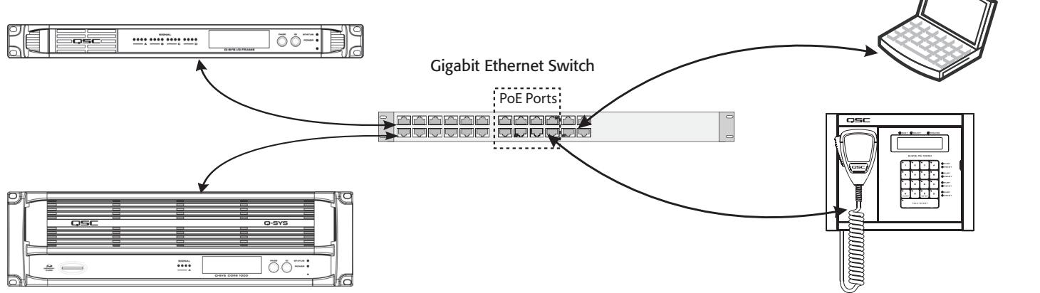
Q-Sys I/O Frame
Provides the means for audio input and output to the Q-LAN network
Q-Sys Core
Provides signal processing, distribution and management services for the Q-Sys system. All time-sensitive audio and management communications traverse the Q-LAN network.
Sys Page Station
In conjunction with the Q-Sys Core, the Page Station provides paging services for the Q-Sys system. All audio and management communication traverse the Q-LAN network.
Figure 1
Windows Based Computer
A PC or laptop running Q-Sys Designer or remote management application. This computer is required only during the design and configuring the system. The computer is not required for runtime operation, though it may be used for on-going system management.
Features
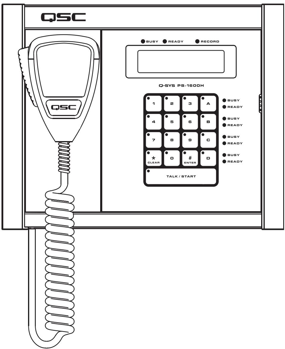
Q-Sys PS-1600H Front Panel
Refer to Figure 2. To see the keypad configurations of Page Station models PS-1650, PS-800, and PS-400, see page 15.
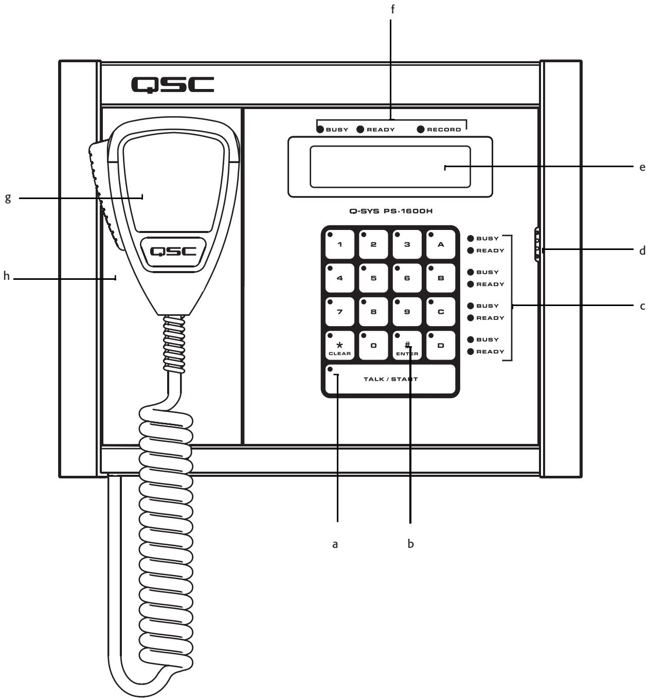
Figure 2
a. LED touch indicators
b. Capacitive Touch Keypad
c. Busy and Ready Indicators for Command Buttons
d. Button Monitor Speaker
e. LCD - 240 x 64 Monochrome Graphics Display
f. Global Busy, Ready and Record Indicators
g. Dynamic Push-to-talk Microphone (PS-XX00H only) Goosenck models use the Talk/Start button to make the page.
h. Magnetic Microphone Docking Plate (PS-XX00H only)
LED Touch Indicators
When a key is pressed, the LED on that key illuminates to indicate that it was pressed.
Capacitive Touch Keypad
- Command buttons can be assigned one of several different types of Commands using the Q-Sys Designer Administration Interface. Once assigned, you just have to press the appropriate Command button to initiate the action.
- Use the number keys to enter Command Codes to initiate PA System actions (PS-1600 only)
- Use the number keys to enter the User PIN (if the Page Station requires user logon) (PS-1600 only)
- Press Clear (*) to clear keyed-in Codes prior to pressing Enter (#). (PS-1600 only)
- Press Clear (*) twice to log off of the Page Station. (PS-1600 only)
- Press Enter (#) to begin a page once the Code is entered. (PS-1600 only)
- Press Enter (#) to logon once the User PIN is entered. (PS-1600 only)
Talk/Start Button
- Tap the Talk/Start button one time to begin a page (tap-on). Tap the button a second time to end the page (tap-off). If you tap-off during the page, the page is logged as completed successfully. If you tap-off during the preamble, the page is logged as cancelled.
- Press and hold the Talk/Start button to begin a page. Release the button to end the page. If you release the button during the page, the page is logged as completed successfully. If you release the button during the preamble, the page is logged as canceled.
- Double-tap the Talk/Start button to clear an entry. (equal to pressing the Clear (*) button)
Busy and Ready Indicators for Command Buttons
- The red Busy LED indicates that the Command is in use by another Page Station.
- The green Ready LED indicates that you can initiate that Command.
Button Monitor Speaker
Produces a "beep" when a button is pressed.
LCD - 240 x 64 Monochrome Graphics Display
The LCD displays various messages including user instructions, the status of the Page Station, status of pages, and so on. The information displayed varies between models.
Global Busy, Ready, and Record Indicators
- Busy (red) illuminates when the selected Command has a queuing mode of Live, and one or more of the PA Zones associated with the Command is in use by another station.
- Ready (green) illuminates when the selected Command has a queuing mode of Live, and all of the PA Zones associated with your Command are available for use. If the queuing mode of the Command is Automatic, the Ready LED is illuminated at all times because the page is recorded if the zones are not available. In Delayed queuing mode the Ready LED is illuminated at all times because the page is recorded regardless of zone status.
- Record (red) illuminated indicates that the page you are making is being recorded. The Queuing method for your page must be Automatic, and one or more of the PA Zones associated with the page must be in use, or the queuing mode of the Command is Delayed. The message will be played once all associated PA Zones are free.
Microphone
A Dynamic Push-to-Talk microphone is available with handheld model Page Stations only. The handheld models are designated by the letter H in the model number. Goosenck microphone models must use the TALK/START button to make the page. Goosenck models are designated by the letter G in the model number.
Magnetic Microphone Docking Plate
The Q-Sys Page Station uses a magnetic docking plate to hold the handheld microphone. Just place the back of the microphone up against the plate and let it go! Available with handheld microphone models only.
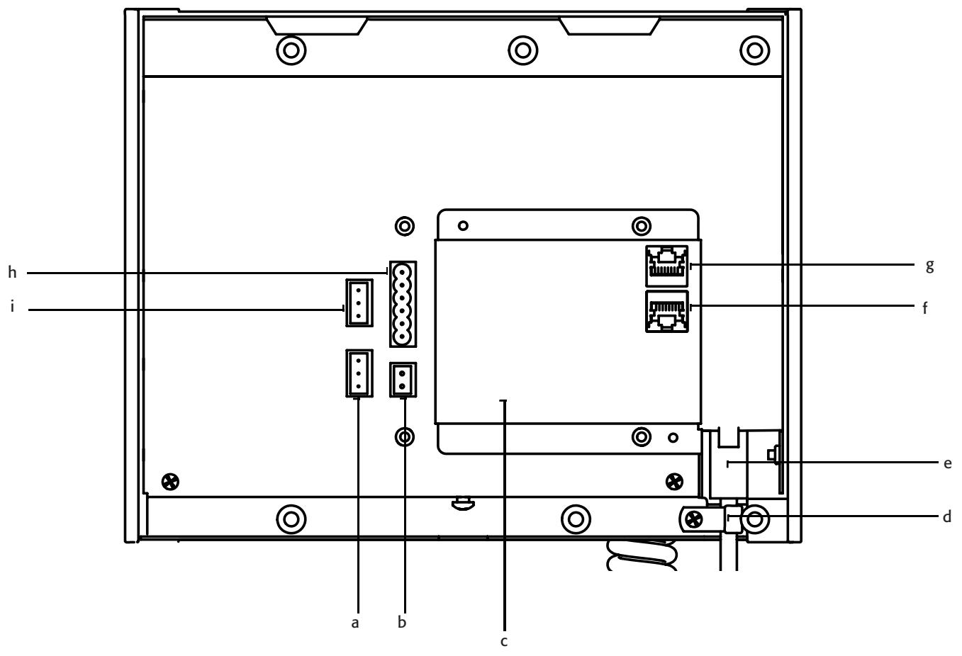
Figure 3
a. MIC LINE (ln) (three-pin Euro connector)
f. Q-Sys LAN B (RJ45 connector)
b. AUX POWER (two-pin Euro connector)
g. Q-Sys LAN A (RJ45 connector)
c. Connector labels
h. GPIO connector (six-pin Euro connector)
d. Strain Relief (Handheld only)
i. LINE OUT (three-pin Euro connector)
e. Microphone Connector - RJ45 (Handheld only)
MIC/LINE In
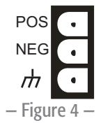
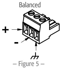
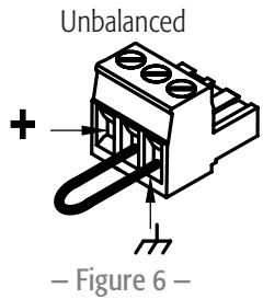
The Page Station rear panel includes an auxiliary MIC/LINE input for support of a secondary microphone or other audio source. The MIC/LINE accepts a Euro style (Phoenix) three-terminal plug, included in the Page Station package. Follow the Page Station rear panel pin-out labels (Figure 4) for wiring. Figure 5 and Figure 6 indicate appropriate termination practices for balanced and unbalanced applications.
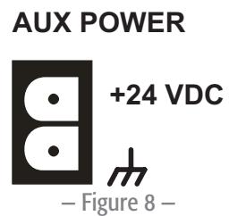
AUX POWER
The Page Station rear panel includes a receptacle for connecting a +24VDC / 500mA power source. This is an optional supply source to power the Page Station, and can be used as the only power source or as a backup power source should PoE fail. The power receptacle on the rear panel of the Page Station accepts a Euro style (Phoenix) two-terminal plug (Figure 7), included in the Page Station package. Follow the Page Station rear panel pinout label (Figure 8) when connecting to this receptacle.
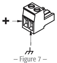
CAUTION!: The power supply used to provide 24 VDC power to the unit shall be a UL Listed ITE power supply, marked LPS, or a UL Listed direct plug-in power unit, marked Class 2, with a rated output of 24 VDC/500 mA.
Microphone Connector
- RJ45 connector for hand-held microphone models.
- XLR connector for gooseneck microphone models.
Strain relief
Secures the cord of the handheld microphones to remove any stress to the RJ45 connector.
Q-LAN Network
Connect one end of a data communications cable (CAT-5e rating or better) terminated with an RJ45 connector into the LAN A (and optionally the LAN B) connector on the rear panel of the Q-Sys Page Station (Figure 9). Ensure that the lock tab on the cable's connector engages with the RJ45 connector on the rear panel. Ensure that the mating network switch port offers IEEE 802.3af compliant power if powering the Page Station via PoE. Refer to the Q-Sys online help for Networking details.
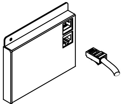
Figure 9
GPIO Connector
The Page Station rear panel includes a six-terminal receptacle (Figure 10, and Figure 12) that provides various GPIO (General Purpose Inputs and Outputs) that allows the Page Station to control or be controlled by a variety of external products. The Page Station GPIO receptacle accepts Euro style (Phoenix) two, three or six-terminal plugs. A six-terminal plug is included in the Page Station ship kit. Follow the Page Station rear panel pin out labels (Table 1) when connecting to the GPIO receptacle. Refer to the Q-Sys online help for GPIO details.

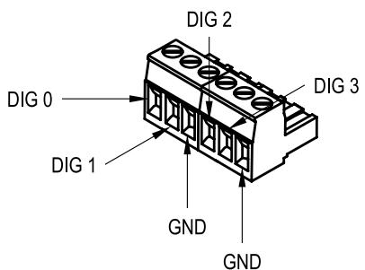
Figure 10
Figure 11
- Table 1 -
| Signal Name | Description |
| Dig 0 | Digital pin |
| Dig 1 | Digital pin |
| GND | Ground |
| Dig 2 | Digital pin |
| Dig 3 | Digital pin |
| GND | Ground |
LINE OUT
The Page Station rear panel includes an auxiliary Line Output receptacle to drive an amplifier or console input directly. The Line Output may be used for mission critical or alternative event applications. The receptacle accept a Euro style (Phoenix) three-terminal plug, which are included in the Page Station package. Follow the Page Station rear panel pin-out labels (Figure 12) when connecting to the receptacle. Figure 13 and Figure 14 indicate appropriate termination practices for balanced and unbalanced applications.

Figure 12
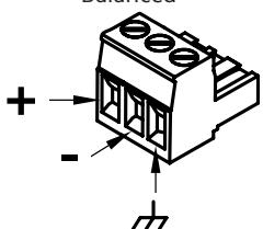
Figure 13
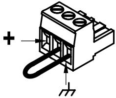
Unbalanced
Figure 14
Page Station Configuration and Setup
Q-Sys Designer is the software application required to configure your paging system. Refer to the Q-Sys Designer online help for details.
This section covers connecting the hardware to the Q-LAN network, powering up, and re-setting the Page Station to the factory defaults.
Optional Connections
The following are optional, and should be connected prior to powering up the Page Station.
- MIC/LINE (3-Pin Euro)
LINE OUT (3-Pin Euro)
GPIO - AUX POWER (If you make this connection and plan to use PoE, do not turn the auxiliary power supply on until you have made the network connection with PoE turned on. See About PoE and AUX POWER, page 11)
Required Connections
- LAN-A - Connect one end of a CAT-5e cable with an RJ45 connector to the LAN-A connector on the Page Station. Connect the other end of the cable to the Q-LAN network.
- Connect LAN-B in the same way if you are going to be using LAN-B.
When power is supplied to the Page Station it may take several minutes to boot fully. The message "Q-Sys not configured" displays. This message remains until the network details are configured for the Page Station and it is included in a valid paging design.
About PoE and AUX POWER
There is no On/Off switch for the Page Station, making the order in which the power is connected important. The following information describes the events when power is lost based on which power is supplied to the Page Station first.
If AUX POWER is supplied first:
- The Page Station boots using AUX POWER.
If PoE is then connected, it is not used. - If AUX POWER fails, power to the Page Station is lost, the Page Station re-boots using PoE.
-
If PoE fails with AUX POWER still available, there is no effect - PoE was not being used.
-
If PoE is supplied first:
-
The Page Station boots using PoE.
- If AUX POWER is then connected, it is not used.
- If PoE fails, the Page Station switches to AUX POWER. There is no re-boot.
- If AUX POWER fails with PoE still available, there is no effect AUX POWER was not being used.
- If PoE returns, the Page Station remains on AUX POWER.
Using the Page Station Menu
To access the menu, when the "Q-Sys not configured" message is displayed, press and hold the Talk/Start button until the first item in the menu is displayed. Press the Talk/Start button to sequence through the menu pages. The following list shows the six pages with factory default settings. The factory settings are slightly different for each Page Station, below is an example.
Q-Sys Page Station
Model PS-1600H
Name:
Page Station 40ab
LANA
IP Addr 169.254.36.146
Netmask 255.255.0.0
LANB
IP Addr 169.254.55.4
Netmask 255.255.0.0
- Firmware Version
2.0.111
Copyright (C) 2010
QSC Audio Products, LLC.
Reset the Page Station to Factory Defaults
- If the Page Station is part of a running design, do the following:
a. In Q-Sys Designer, from the main menu, select File > Load from Core and Connect. Select the design containing the Page Station you wish to reset.
b. From the main menu, select Tools > Configurator...
c. Select the Page Station you wish to reset.
d. Change the hostname of the Page Station. "Q-Sys not configured" displays on the Page Station LCD.
- Follow the procedure "Using the Page Station Menu" on page 11 to access the menu.
-
Press the Talk/Start button to access the Name, LAN-A, or LAN-B menu page.
-
Insert a reset tool (a paperclip works) into the small hole on the right side of the Page Station to press the reset button. "Clear settings in 10, 9, ..." displays on the Page Station LCD.
- Hold the reset button until the count down gets to 0.
- Release the reset button. The Page Station is reset to factory default settings.
Wall-mounting the Page Station
NOTE: The product shall be installed in accordance with the applicable code requirements.
Q-Sys Page Stations are designed to be mounted on a wall or podium with an appropriate cutout and cavity to allow all cables and power sources to connect to the Page Station rear panel with adequate stress relief. The included Mounting Bracket is designed to mate with a standard triple-gang U.S. electrical box, but does not need one to be mounted. Using an electrical box provides contractors with the option of pre-wiring, then installing the Page Station at a later time; if an electrical box is used, its dimensions should meet the NEMA standards. The Mounting Bracket should be firmly attached to the wall using the electrical box (if installed) for alignment only.
- Remove the Mounting Bracket from the Page Station. It is secured by one screw on the bottom of the Page Station. Set the screw aside for later use.
- Route all Page Station wiring and connectors through the center of the Mounting Bracket.
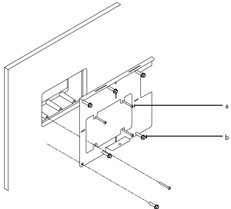
Figure 15
a. Four included screws for aligning the Mounting Bracket to the triple-gang box.
b. Six user-supplied screws, appropriate for mounting surface
- Use four (included) (Figure 15 a) to align and mount the Mounting Bracket to the triple-gang electrical box if you are using one.
- Use six screws (not included) (Figure 15 b) to secure the Mounting Bracket to the wall. The six screws shall be appropriate for the surface to which the Page Station is mounted.
IMPORTANT! These six screws are required, even when using the triple-gang electrical box.
- Connect all Page Station wiring to the proper connectors on the Page Station. Refer to "Q-Sys Page Station Rear Panel" on page 8.
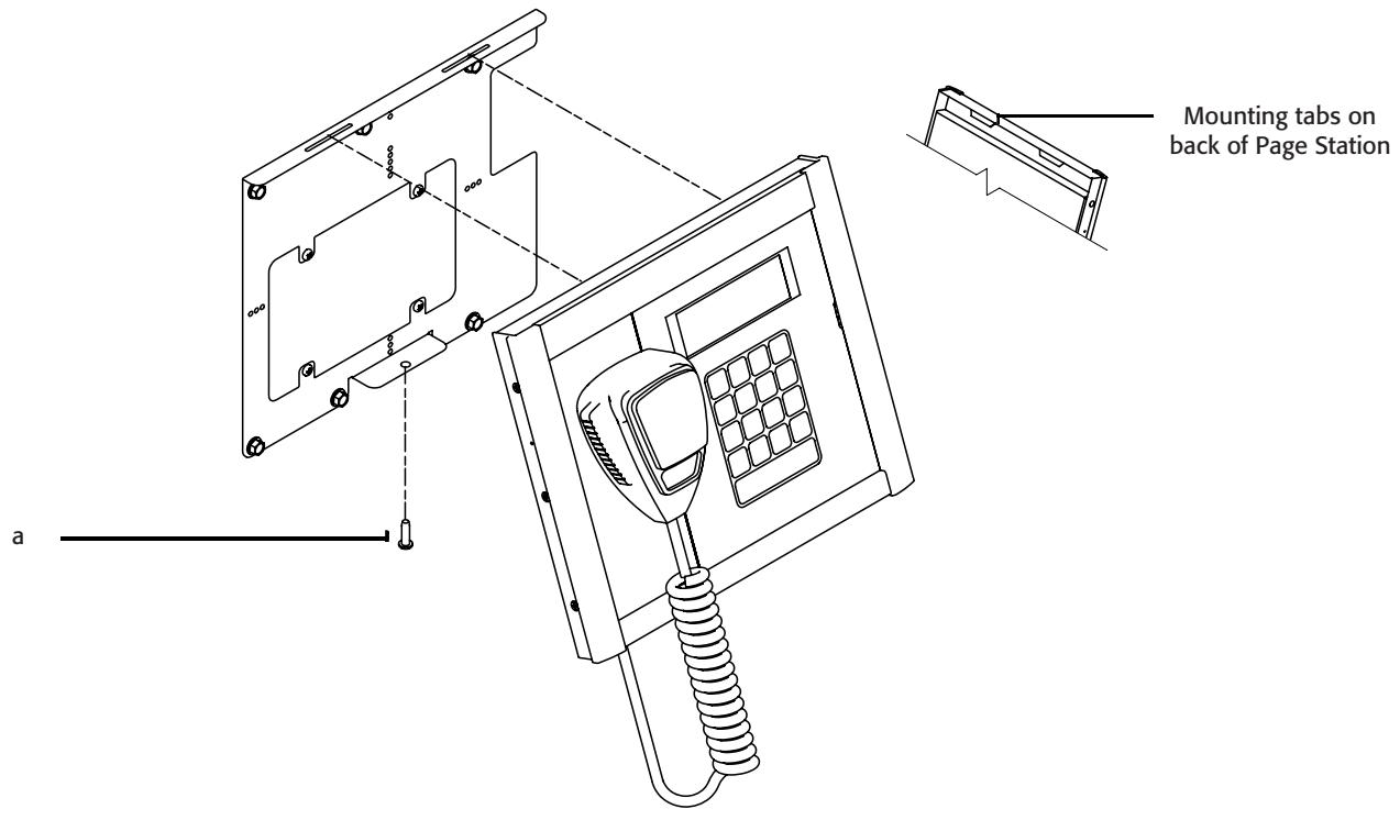
Figure 16
- Tilt the top of the Page Station back and install the Page Station onto the Mounting Plate by aligning the two tabs on the Page Station with the two slots on the Mounting Plate. Refer to Figure 16.
- With the Page Station still tilted, carefully bundle the wiring back into the wall (or triple-gang electrical box).
- Push the bottom of the Page Station to the wall.
- Install and tighten the screw (Figure 16a) removed in step 1, through the Mounting Bracket up into the Page Station.
Specifications
- Table 2 -
| Hardware | |
| Dimensions (H/W/D) | 10.37" x 8.3" x 1.5" (263.4 mm x 210.8 mm x 38.1 mm) |
| Line voltage requirements | IEEE 802.3af power or +24 VDC/500 mA |
| Accessories included | Hardware User Manual, Accessory ship kit, Warranty card |
| Audio Channel Capacity | |
| Line Inputs | 2 |
| Line Outputs | 1 |
| Front Panel Controls | |
| Paging keypad | Capacitive touch keypad, PTT momentary button |
| Microphone | PTT momentary switch (Handheld models only) |
| Front Panel Connectors | |
| Goosenck microphone | XLR (Goosenck models only) |
| Front Panel Indicators | |
| Talk, Ready, Busy | Bi-color LEDs (red/green) |
| Keypad button activity | Green LEDs |
| LCD | 240x64 monochrome graphics display |
| Rear Panel Connectors | |
| Hand-held microphone | RJ45 |
| Q-LAN Network LAN A | RJ45 1000 Mbps only |
| Q-LAN Network LAN B | RJ45 1000 Mbps only |
| DC power +24 VDC inlet | 2-pin Euro receptacle |
| Line Input | 3-pin Euro receptacle |
| Line Output | 3-pin Euro receptacle |
| GPIO | 6-pin Euro receptacle |
| Line Input | |
| Dynamic range | |
| Unweighted | >115 dB |
| A-weighted | >118 dB |
| Distortion (20 Hz - 20 kHz, all sensitivities) | |
| +4 dBU (max) | <0.009% THD+N |
| 2 dB below clip (max) | <0.009% THD+N |
| Crosstalk (20 Hz - 20 kHz) | |
| Inter-channel (max) | >75 dB |
| Inter-channel (typ) | >90 dB |
| Intra-channel (max) | >85 dB |
| Intra-channel (typ) | >100 dB |
| Frequency response | |
| 20 Hz - 20 kHz (max) | ± 0.5 dB |
| 20 Hz - 20 kHz (typ) | ± 0.2 dB |
| Input impedance | |
| Balanced (nominal) | 10k ohms |
| Unbalanced (nominal) | 10k ohms |
| Common mode rejection: | |
| 20 Hz - 20 kHz (min) | >54 dB |
| 20 Hz - 20 kHz (typ) | >60 dB |
| Input sensitivities: | |
| Vrms | 1.5, 3, 9, 18 |
| dBu | 5.7, 11.8, 21.3, 27.3 |
| dBv | 3.5, 9.5, 19.1, 25.1 |
| Line Output | |
| Dynamic range | |
| Unweighted | >112 dB |
| A-weighted | >115 dB |
| Crosstalk (20 Hz - 20 kHz) | |
| Inter-channel (max) | >75 dB |
| Inter-channel (typ) | >90 dB |
| Intra-channel (max) | >85 dB |
| Intra-channel (typ) | >100 dB |
| Mute | Infinite attenuation |
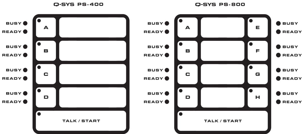
Keypad Configurations
Figure 18

Figure 19
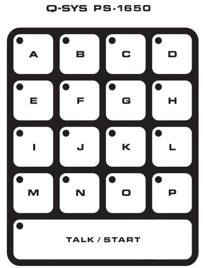
Figure 20
Mailing Address:
QSC Audio Products, LLC
1675 MacArthur Boulevard
Costa Mesa, CA 92626-1468 USA
Telephone Numbers:
Main Number: (714) 754-6175
Sales & Marketing: (714) 957-7100 or toll free (USA only) (800) 854-4079
Customer Service: (714) 957-7150 or toll free (USA only) (800) 772-2834
Facsimile Numbers:
Sales & Marketing FAX: (714) 754-6174
Customer Service FAX: (714) 754-6173
World Wide Web:
www.qscaudio.com
E-mail:
info@qscaudio.com
service@qscaudio.com