TX2000 - Fastening tool AVDEL - Free user manual and instructions
Find the device manual for free TX2000 AVDEL in PDF.
Download the instructions for your Fastening tool in PDF format for free! Find your manual TX2000 - AVDEL and take your electronic device back in hand. On this page are published all the documents necessary for the use of your device. TX2000 by AVDEL.
USER MANUAL TX2000 AVDEL
Before Starting Charging Procedure Battery Handling Nose Equipment 8-9
Changing Nose Equipment
Servicing the Tool Daily/Weekly/Annually Parts List
Safety Data Grease and oil
LIMITED WARRANTY Avdel makes the limited warranty that its products will be free of defects in workmanship and materials which occur under normal operating conditions. This Limited Warranty is contingent upon: (1) the product being installed, maintained and operated in accordance with product literature and instructions, and (2) confirmation by Avdel of such defect, upon inspection and testing. Avdel makes the foregoing limited warranty for a period of twelve (12) months following Avdel’s delivery of the product to the direct purchaser from Avdel. In the event of any breach of the foregoing warranty, the sole remedy shall be to return the defective Goods for replacement or refund for the purchase price at Avdel’s option. THE FOREGOING EXPRESS LIMITED WARRANTY AND REMEDY ARE EXCLUSIVE AND ARE IN LIEU OF ALL OTHER WARRANTIES AND REMEDIES. ANY IMPLIED WARRANTY AS TO QUALITY, FITNESS FOR PURPOSE, OR MERCHANTABILITY ARE HEREBY SPECIFICALLY DISCLAIMED AND EXCLUDED BY AVDEL. Avdel UK Limited policy is one of continuous product development and improvement and we reserve the right to change the specification of any product without prior notice.
Safety Rules This instruction manual must be read with particular attention to the following safety rules, by any person installing, operating, or servicing this tool.
Do not use outside the design intent.
Do not use equipment with this tool other than that recommended and supplied by Avdel UK Limited.
The tool must be maintained in a safe working condition at all times. The operator must follow the daily and weekly service checks detailed on page 13.
The tool shall at all times be operated in accordance with the relevant health and safety legislation. Any question regarding the correct operation of the tool and operator safety should be directed to your local Avdel UK Limited company or authorized representative.
Do not operate a tool that is pointed towards any person(s).
Ensure that vent holes do not become blocked or covered.
Do not operate the tool if it is not fitted with a complete nose assembly.
The stem collector must be emptied when half full.
When using the tool, the wearing of safety glasses is required both by the operator and others in the vicinity to protect against fastener ejection, should a fastener be placed ‘in-air’. We recommend wearing gloves if there are sharp edges or corners on the application. 10 Take care to avoid entanglement of loose clothes, ties, long hair, cleaning rags etc., in the moving parts of the tool which should be kept dry and clean for best possible grip. 11 When carrying the tool from place to place keep hands away from the trigger to avoid inadvertent start up. 12 Excessive contact with hydraulic oil should be avoided. To minimise the possibility of rashes, care should be taken to wash thoroughly. 13 Do not operate the tool or the charger in an environment allowing exposure to moisture, rain, combustible fluids or gasses. 14 Regularly check the plug, cord and charger and in case of damage have repairs completed by an authorized Avdel representative. 15 Remove the battery when not in use, or before servicing / repairing the tool. 16 Do not discard batteries into water or fire, (danger of explosion). The battery must be disposed of in accordance with environmental regulations.
English Specifications T O O L S P E C I F I C AT I O N Stroke Minimum - Maximum
Operating Voltage Cycle time 12V DC Approx. @ Full Stroke Noise Level
70 dB(A) Vibration Less than
Weight With nose equipment
The tool will be supplied with either of the two charger types listed below. To identify the correct type, please refer to the specification number on the charger label. C H A R G E R S P E C I F I C AT I O N Input Supply AP-HBW/tu 1203 UK/Europe/Australia 220/240 V (50 Hz) USA/Canada/Japan 110V (60Hz) Output Supply 12 V (3A) Charging Time 12 V/2.0 Ah battery Intelligent Charger Charges according to remaining battery charge Battery Type Suitable for cell chemistry Ni-Cd and Ni-MH Weight 40 minutes
C H A R G E R S P E C I F I C AT I O N
Output Supply Charging Time 12 V/2.0 Ah Ni-Cd battery (90% Capacity) 40 minutes 12 V/2.0 Ah Ni-Cd battery (100% Capacity) 50 minutes Advanced Intelligent Charger Patented design. Charges according to remaining battery capacity with automatic trickle charge to achieve optimum battery capacity Battery Type Suitable for charging both Ni-Cd and Ni-MH cell chemistry with a capacity of 1.2Ah-3.0Ah. Weight
B AT T E RY S P E C I F I C AT I O N Output Voltage 12V DC Capacity
Cell Construction Ni-Cd (with NTC thermal overcharge protection) Weight
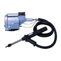
Intent of Use The TX2000 is a battery powered hydraulic tool designed for placing Avdel® breakstem fasteners from 3.0mm to 6.4mm (1/4”) as shown in the table below and detailed on page 7. IMPORTANT: The tool, battery and charger must be used in accordance with the operating instructions and safety rules contained within this manual. The placing of other fastener sizes or materials not included in the table on page 7 could have a detrimental impact on the working life of the tool and could invalidate the warranty. The tool should only be dismantled by a Avdel® authorized distributor or repair centre. Failure to do so could invalidate the warranty. S TA N D A R D T O O L K I T The standard tool kit consists of:
- A battery powered hydraulic tool
- A nose assembly and three nose tips
- A battery and charger
- An Instruction Manual These are housed in a durable storage case. S TA N D A R D N O S E T I P S The three nose tips and nose assembly supplied as standard with the tool make up a nose assembly part kit (71210-15100). These nose tips will place the range of Avdel® breakstem fasteners summarised below. Standard Nose Tip Fastener Size Fastener Material 71210-05002 3.0mm – 3.2mm (1/8") Aluminium / Stainless Steel / Copper 71210-16070 3.2mm (1/8") Steel / Stainless Steel 4.0mm (5/32") Aluminium / Stainless Steel / Copper 4.0mm (5/32") Steel / Stainless Steel 4.8mm (3/16") Aluminium 07381-04701 Please refer to the matrix on page 7 for a full list of the fastener materials and sizes the TX2000 will place along with the nose tip part numbers required to place them.
Copper Stainless Steel 4.3mm 4.8mm (3/16") 3.2mm (1/8")
Before Starting Before starting, please read and follow the operating instructions carefully. CHARGING PROCEDURE AP-HBW/tu 1203
- The charger must only be used with Avdel® batteries.
- Take the charger out of the case and connect to the mains power supply. The solid red LED indicates that the charger is operational.
- Insert the battery correctly into the charger with minimal force.
- If the green LED flashes when the battery is inserted this indicates that the battery is too hot. Remove the battery and allow to cool before trying again.
- The battery charging process is indicated by a solid green LED.
- Re-charging takes up to 40 minutes, depending upon the level of charge remaining within the battery.
- The end of the charging process is indicated by the flashing green LED. CHARGING PROCEDURE
AP/ULE-1201 & AP/ULUJ-1201
- The charger must only be used with Avdel® batteries.
- Take the charger out of the storage case and connect to the mains power supply. The Left LED will be SOLID RED. The Right LED will be SOLID GREEN for 2 seconds - in this time a self-test will be performed - indicating that the charger is operational.
- If the LH LED FLASHES RED this indicates that the charger is not functioning correctly - charging is not possible. If this occurs please contact an authorised Avdel® representative.
- Insert the battery correctly into the charger with minimal force.
- The battery charging process is indicated by the SOLID GREEN RH LED.
- If the RH LED FLASHES RED when the battery is inserted this indicates that the battery is too hot. Remove the battery from the charger and allow it to cool before trying again. This will occur when the battery temperature is above 65°C and can result if the battery is inserted directly after charging or discharging.
- If the RH LED shows SOLID RED this indicates that the battery is faulty. Remove battery from the charger and do not use.
- A SOLID YELLOW RH LED indicates that the battery is at least 90% charged. Removing the battery at this point will increase the service life of the battery. No significant reduction in the performance of the battery will result.
- A FLASHING GREEN RH LED indicates that the charging process is complete. The battery will now be at 100% capacity. At this point the battery will be trickle charged until removed. Overcharging of the battery will not occur.
- When charging a Ni-MH battery the RH LED can be seen to FLASH RED & GREEN. This also indicates that the charging process is complete.
English Before Starting A summary of the charger LED signals are shown in the table below:
Solid Red LED: Charger Operational Solid Green LED: Charging In Progress Flashing Red LED: Charger Faulty - Do not use Solid Yellow LED: Battery At Least 90% Charged Flashing Green LED: Charging Process Complete 100% Charged Flashing Red & Green Charging Process Complete - LED: Ni-MH Solid Red LED: Battery Faulty Or Damaged Do Not Use Flashing Red LED: Battery Too Hot Or Cold To achieve the optimum performance from the battery, please adhere to the following guidelines when charging:
- Aim to charge when both the battery and charger are cool. Optimum charge capacity is achieved when charging a battery at 28°C.
- A new battery will only reach full capacity after several charges.
- To increase the service life of the battery, remove from the charger when the RH LED shows solid yellow.
- To increase the service life of the battery, only re-charge when no further fasteners can be placed.
- To achieve the maximum number of cycles from a battery use directly after charging. B AT T E RY H A N D L I N G & D I S P O S A L
- Batteries must only be charged using the Avdel® charger supplied.
- Only re-charge batteries when cool. Optimum charge capacity is achieved at 28°C.
- The battery can be charged up to 1000 times. Optimum life is achieved when used at 22°C. The battery will reach its full capacity only after several charges.
- The surrounding temperature must not exceed 50°C (122°F) or be below -40°C (-40°F) for the battery to operate.
- For optimum life and performance only re-charge the battery when no further fasteners can be placed.
- For optimum performance use the battery directly after re-charging.
- Significantly reduced operating time of the battery after a complete re-charge indicates that the battery needs replacing.
- Store the battery in a frost free and dry environment.
- To ensure that the batteries are disposed of correctly please return to an authorized recycling centre.
- Used batteries must not get into waste, fire or water under any circumstance.
Before Starting NOSE EQUIPMENT
- A complete tool includes the nose assembly kit 71210-15100 with the following three nose tips as standard: 71210-05002, 71210-16070 and 07381-04701 (Please refer to page 7 for details of the range of fasteners they will place). Nose tip 07381-04701 is supplied fitted to the nose assembly and the other two are screwed into the front end of the tool.
- It is important that you check that the nose tip already fitted to the nose assembly is the correct one to place your fastener by sliding the fastener stem into the nose tip. No force should be required and play should be minimal.
- To change nose equipment, please refer to the instructions and list of components on page 12.
Operating Procedure English O P E R AT I N G P R O C E D U R E
- Connect the charged battery to the tool.
- Insert the fastener stem into the nose of the tool. If using a standard nose tip the fastener must be held manually until placed into the application.
- Bring the tool with the fastener to the application so that the protruding fastener enters the hole of the application squarely.
- Fully actuate the trigger. The tool will cycle and place the fastener. Release the trigger only when the fastener stem has broken, the piston will then return to the forward position.
- After each cycle, the spent fastener stem must be disposed of by tilting the tool nose up, allowing the stem to fall back into the collection container at the rear of the tool.
- If the trigger is not released the tool will stop after approximately 4 seconds of operation, preventing overload. Releasing the trigger will reset the control circuit allowing the tool to operate as before.
- Empty the collection container when more than half full of stems.
- To empty the collection container tilt the tool nose down and lift the collector lid.
- Please read daily servicing details on page 13. To achieve the optimum performance from the tool, please adhere to the following guidelines when operating:
- Fully depress the trigger when placing fasteners to achieve the optimum cycle rate, pull-force and efficiency.
- Release the trigger immediately after the rivet stem has broken in order to gain the maximum number of cycles from the battery.
- Do not operate the tool to the point of pressure relief and motor cut-out. These features are only to protect the tool from operator overload and abuse. Continual operation in this way will rapidly drain the battery.
Changing Nose Equipment
CHANGING NOSE EQUIPMENT
IMPORTANT: The battery must be disconnected when fitting or removing the nose assemblies. Item numbers in bold refer to nose assembly components illustrated below.
- Remove items in reverse order to that shown below
- Lightly coat jaws 4 with Moly-lithium grease.
- Drop jaws 4 into jaw housing 3.
- Insert jaw spreader 5 into the jaw housing 3.
- Locate buffer 6 on the jaw spreader 5.
- Locate spring 7 onto jaw spreader 5.
- Fit locking ring 8 onto the jaw spreader housing of the tool.
- Holding the tool pointing down, screw the assembled jaw housing onto the jaw spreader housing and tighten with spanner.
- Screw the nose tip into nose casing 1 and tighten with nose tip spanner. Nose tip spanner 71600-02024 included with the tool will fit the three nose tips supplied with the tool as standard.
English Servicing the Tool IMPORTANT: The employer is responsible for ensuring that tool maintenance instructions are given to the appropriate personnel. The operator should not be involved in maintenance or repair of the tool unless properly trained. The tool must be examined regularly for damage and malfunction. The following service checks should be performed: D A I LY
- Check for oil leaks*.
- Check that the nose assembly is correct for the fastener to be placed. Please refer to page 7. W E E K LY
- Check for oil leaks*.
- Dismantle and clean the nose assembly with special attention to the jaws using the following procedures:
- Remove the nose equipment using the reverse procedure to the instructions for changing nose equipment on page 12.
- Any worn or damaged part should be replaced.
- Clean and check wear on jaws.
- Ensure that the jaw spreader is not distorted.
- Check spring 7 is not distorted.
- Assemble according to the fitting instructions on page 12. A N N U A L LY (or every 500,000 cycles, whichever is the soonest) Please return your tool to your local Avdel® authorized distributor or repair centre. PA R T S L I S T please refer to page 7 for nose tip part numbers Part No. Description 07007-01954 Battery (Ni-Cd 12V/2.0 Ah) 07007-01977 Battery (Ni-MH 12V/2.2 Ah) 71600-02024 Nose tip spanner 07007-01965 Battery charger: 220/240V~50Hz (UK) 07007-01966 Battery charger: 220/240V~50Hz (Europe) 07007-01967 Battery charger: 220/240V~-50Hz (Australia) 07007-01968 Battery charger: 110V~60Hz (USA/Canada) 07007-01969 Battery charger: 100V~50/60Hz (Japan) 07007-01960 Storage case 07900-00759 Tool Instruction Manual - UK version 07992-00020 Moly-lithium grease 07992-00076 Hyspin® AWS 15 oil (0.5 litre) 07992-00077 Hyspin® AWS 15 oil (1 gallon) 07900-00754 Priming pump
- please refer to page 14 for relevant safety data
Priming Procedure PRIMING PROCEDURE Priming may be necessary after considerable use. Oil Details The recommended oil for priming is Hyspin® AWS 15 available in 0.5 litre (part number 07992-00076) or one gallon containers (part number 07992-00077). Please refer to page 17 for safety data. Procedure To enable you to follow the priming procedure below, you will need to obtain a priming kit:
IMPORTANT: REMOVE NOSE ASSEMBLY
All operations should be carried out on a clean bench, with clean hands in a clean area. Ensure that the oil is perfectly clean and free from air bubbles. Care MUST be taken at all times, to ensure that no foreign matter enters the tool, or serious damage may result.
- Remove the nose casing from the tool following the instructions on page 12, in reverse order.
- Remove screws and seals from cylinder bleed point, position 1, and reservoir inlet point, position 2, as illustrated on page 15.
- Invert the tool over a suitable container and actuate the trigger with the battery connected. Waste oil will be ejected through the bleed screw hole in the cylinder, position 1.
- Replace screw and seal in the cylinder, position 1 only.
- Hold the tool nose up in a vice using soft jaws to avoid damage. DO NOT USE UNDUE FORCE WHEN CLAMPING THE VICE ON THE TOOL.
- Completely fill the priming pump 07900-00754 with oil.
- Screw the priming pump 07900-00754 into the reservoir inlet point, position 2 with the seal in place.
- Gently pump the bellows on the priming pump repeatedly, inserting oil into the tool and allowing air to be collected in the priming pump. Continue this process until no further air bubbles are removed from the tool. The reservoir should now be full of oil. (Please refer to the diagram on page 15, position 2.)
- With the battery connected, actuate the trigger and gently compress the priming pump until the piston begins to move. Oil will then be drawn into the tool.
- Release the trigger and priming pump allowing the pump bellows to expand and suck air from the tool. Air bubbles will be visibly expelled from the reservoir inlet point, position 2, into the priming pump.
- Actuate the trigger and cycle the tool until the piston reaches full stroke. Release the trigger allowing the piston to return and air bubbles to be expelled into the priming pump. Repeat this procedure until no further air bubbles are expelled into the priming pump. Allow several seconds between each cycle so that the air bubbles have time to collect in the priming pump.
- Remove the priming pump from the reservoir inlet point, position 2, taking care not to spill excess oil over the tool.
- Top up the reservoir, position 2, to ensure that the tool is completely filled with oil.
- Replace screw and seal in the reservoir, inlet point, position 2.
- Replace the nose casing.
English Priming Diagram Priming Pump Position 1 Cylinder Bleed Point Position 2 Reservoir Inlet Point
Troubleshooting SYMPTOM POSSIBLE CAUSE REMEDY More than one Low battery charge Charge or if necessary replace battery operation of the Worn or broken jaws Fit new jaws trigger needed to Low oil level or air present in oil Prime tool place fastener Build up of dirt inside nose assembly Service nose assembly Fastener fails Fastener outside tool capability Contact Avdel Limited to break Low battery charge Charge or if necessary replace battery Low oil level or air present in oil Prime tool Low battery charge Charge or if necessary replace battery Low oil level or air present in oil Prime tool Build up of dirt inside nose assembly Service nose assembly Slow cycle PA G E R E F. 8-9 14-15
Tool will not Worn or broken jaws Fit new jaws
grip stem Build up of dirt inside nose assembly Service nose assembly
of fastener Loose jaw housing Tighten against locking ring
Weak or broken spring in nose assembly Fit new spring
Incorrect component in nose assembly Identify and replace
Jaws will not Build up of dirt inside nose assembly Service nose assembly
release broken Jaw housing, nose tip or nose casing Tighten nose assembly
stem of fastener not properly seated Weak or broken spring in nose assembly Fit new spring
Check jaw spreader is correct
Cannot feed next fastener Tool fails to Low oil level or air present in oil Prime tool 14-15 operate – motor operational Tool fails to Low battery charge Charge or if necessary replace battery 8-9 operate – motor Battery not connected Connect fully charged battery 8-9 not operational Other symptoms or failures should be reported to your local Avdel® authorized distributor or repair centre.
English Safety Data (Grease and Oil) M O LY - L I T H I U M G R E A S E E P 3 7 5 3 H Y S P I N ® A W S 1 5 O I L S A F E T Y D ATA S A F E T Y D ATA First Aid First Aid SKIN: SKIN: As the grease is completely water resistant it is best Wash thoroughly with soap and water as soon as possible. removed with an approved emulsifying skin cleaner. Casual contact requires no immediate attention. Short INGESTION: term contact requires no immediate attention. Ensure the individual drinks 30ml Milk of Magnesia, INGESTION: preferably in a cup of milk. Seek medical attention immediately. DO NOT induce EYES: vomiting. Irritant but not harmful. Irrigate with water and seek EYES: medical attention. Irrigate immediately with water for several minutes. Although NOT a primary irritant, minor irritation may occur Fire following contact. FLASH POINT: Above 220°C. Not classified as flammable. Fire Suitable extinguishing media: CO2, Halon or water spray if Suitable extinguishing media: CO2, dry powder, foam or applied by an experienced operator. water fog. DO NOT use water jets. Environment Environment Scrape up for burning or disposal on approved site. WASTE DISPOSAL: Through authorised contractor to a licensed site. May be incinerated. Unused product may be Handling Use barrier cream or oil resistant gloves Storage Away from heat and oxidising agent. sent for reclamation. SPILLAGE: Prevent entry into drains, sewers and water courses. Soak up with absorbent material. Handling Wear eye protection, impervious gloves (e.g. of PVC) and a plastic apron. Use in well ventilated area. Storage No special precautions. These products can be ordered separately. Please refer to the parts list on page 13 for part numbers.
Declaration of Conformity We, Avdel UK Limited, Watchmead Industrial Estate, Welwyn Garden City, Herts, AL7 1LY declare under our sole responsibility that the product: Model TX2000 Serial No.
to which this declaration relates is in conformity with the following standards: TX2000 Tool Battery Charger EN292 part 1 and part 2 VDE0700 Pr EN50260 Part 1 EN 60335-1 BS EN982 EN 60335-2-29 ISO 8662 part 1 EN 60742/0695 ISO 3744 EN 50081-1 ISO PREN792 part 14 EN 55014 BS EN55014 part 1 EN 60555-2/3 BS EN50081 part 1 EN 50082-1 BS EN55014 part 2 EN 55104 following the provisions of the Machine Directive 89/392/EC (as amended by Directive 91/368/EC, 93/44/EC) and 93/68/EC A. Seewraj - Product Engineering Manager - Automation Tools Date of issue This box contains a power tool which is in conformity with Machines Directive 89/392/EC. The ‘Declaration of Conformity’ is contained within.
BESCHRÄNKTE GARANTIE
Rame 4,3mm 4,8mm (3/16") 3,2mm (1/8")
Hertfordshire SINGAPORE Manual No. © Avdel UK Limited 2007 AUSTRALIA Avdel®, Avdel® SR, Avex®, Avibulb®, Avinox®, Avseal®, Bulbex®, Genesis®, Interlock®, MBC®, MBC®/LC, Monobolt®, Stavex®, T-Lok®, TLR® are trademarks of Avdel UK Limited. www.avdel-global.com