
0753 MKII 07530 MKII - Pneumatic tool AVDEL - Free user manual and instructions
Find the device manual for free 0753 MKII 07530 MKII AVDEL in PDF.
User questions about 0753 MKII 07530 MKII AVDEL
0 question about this device. Answer the ones you know or ask your own.
Ask a new question about this device
Download the instructions for your Pneumatic tool in PDF format for free! Find your manual 0753 MKII 07530 MKII - AVDEL and take your electronic device back in hand. On this page are published all the documents necessary for the use of your device. 0753 MKII 07530 MKII by AVDEL.
USER MANUAL 0753 MKII 07530 MKII AVDEL
Putting into Service
Air Supply 8
Mechanical Cursors 9
Cursor 10
Loading and Re-loading the Tool 10-11
Operating Procedure 11
Mandrel Follower Springs Identification 12
and Orientation
Nose Assemblies
Nose Jaws 13
Selecting a Nose Jaw 14
Nose Jaw Selection Tables 15-16
Mandrels and Mandrel Follower Springs 17
Chobert® and Grovit® Selection Tables 17-18
Briv® Selection Tables 19-20
Mandrel Head Types and 'P' Length 20
Avlug, Avsert, Avtronic and Rivscrew 21
Selection Tables
Servicing the Tool
Daily/Weekly 22
Moly Lithium Grease EP 3735 Safety Data 22
Service Kit 23
Maintenance
Dismantling 07530-02200 MkII 24-25
Dismantling 07532-02200 MkII 26-27
General Assembly and Parts List 07530-02200 MkII 28-29
General Assembly and Parts List 07532-02200 MkII 30-31
Intensifier 07531-02200 32-33
Pilot valve 07005-00590 Spares Information 34-35
Priming
Oil Details 36
Hyspin VG 32 and AWS 32 Oil Safety Data 36
Priming Procedure 36
Fault Diagnosis
Symptom, Possible Cause & Remedy 37
Francais 41
Deutsch 79
Italiano 117
Warranty
Avdel installation tools carry a 12 month warranty against defects caused by faulty materials or workmanship, the warranty period commencing from the date of delivery confirmed by invoice or delivery note.
The warranty applies to the user/purchaser when sold through an authorised outlet, and only when used for the intended purpose. The warranty is invalidated if the installation tool is not serviced, maintained and operated according to the instructions contained in the Instruction and Service Manuals.
In the event of a defect or failure, and at its sole discretion, Avdel undertakes only to repair or replace faulty components.
This instruction manual must be read with particular attention to the following safety rules, by any person installing, operating, or servicing this tool.
1 Do not use outside the design intent.
2 The Hand Tool and Intensifier have been tested as separate items and combined. They must only be used together and under no circumstances for any other purposes.
3 Do not use equipment with this tool/machine other than that recommended and supplied by Avdel.
4 Any modification undertaken by the customer to the tool/machine, nose assemblies, accessories or any equipment supplied by Avdel or their representatives, shall be the customer's entire responsibility. Avdel will be pleased to advise upon any proposed modification.
5 The tool/machine must be maintained in a safe working condition at all times and examined at regular intervals for damage and function by trained competent personnel. Any dismantling procedure shall be undertaken only by personnel trained in Avdel procedures. Do not dismantle this tool/machine without prior reference to the maintenance instructions. Please contact Avdel with your training requirements.
6 The tool/machine shall at all times be operated in accordance with relevant Health and Safety legislation. In the U.K. the "Health and Safety at Work etc. Act 1974" applies. Any question regarding the correct operation of the tool/machine and operator safety should be directed to Avdel.
7 The precautions to be observed when using this tool/machine must be explained by the customer to all operators.
8 Always disconnect the airline from the tool/machine inlet before attempting to adjust, fit or remove a nose assembly.
9 Do not operate a tool/machine that is directed towards any person(s) or the operator.
10 Always adopt a firm footing or a stable position before operating the tool/machine.
11 Ensure that vent holes do not become blocked or covered and that hoses are always in good condition.
12 The operating pressure shall not exceed 7 bar (100Ibf / in^2)
13 The combination of fastener, mandrel, hole size and sheet thickness shall be in accordance with Avdel Specifications.
14 Do not operate the tool if it is not fitted with a complete nose assembly unless specifically instructed otherwise.
15 When using the tool, the wearing of safety glasses is required both by the operator and others in the vicinity to protect against fastener ejection, should a fastener be placed 'in air'. We recommend wearing gloves if there are sharp edges or corners on the application.
16 Take care to avoid entanglement of loose clothes, ties, long hair, cleaning rags etc. in the moving parts of the tool which should be kept dry and clean for best possible grip.
17 When carrying the tool from place to place keep hands away from the trigger/lever to avoid inadvertent startup.
18 Excessive contact with hydraulic oil should be avoided. To minimize the possibility of rashes, care should be taken to wash thoroughly.
IMPORTANT
While a small amount of wear and marking will naturally occur through normal and correct use of mandrels, they must be regularly examined for excessive wear and marking, with particular attention to the head diameter, the tail jaw gripping area of the shank or heavy pitting of the shank and any mandrel distortion. Mandrels which fail during use could forcibly exit the tool. It is the customer's responsibility to ensure that mandrels are replaced before any excessive levels or wear and always before the maximum recommended number of placings. Contact your Avdel representative who will let you know what that figure is by measuring the broach load of your application with a calibrated test tool. These tools can also be purchased under Part Number 07900-09080, supplied with all necessary information for testing in this manual.
Specification for 0753 Mk II Type Tool
Air Pressure
Minimum - Maximum
5-7 bar (70-100 lbf/in²)
Free Air Volume Required
Intensification Ratio
32:1
The pneumatic 0753 Mkll type tool is designed to place Avdel® speed fasteners (except 1/16 Avlug®) making it ideal for batch or flowline assembly in a wide variety of applications throughout all industries.
The Hand Tool and Intensifier have been tested as separate items and combined. They must only be used together and for no other purposes. Refer to "Putting into Service" on page 8 for connection details.
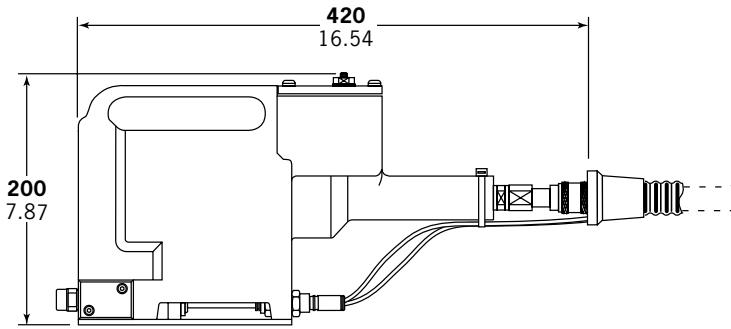
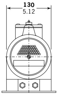
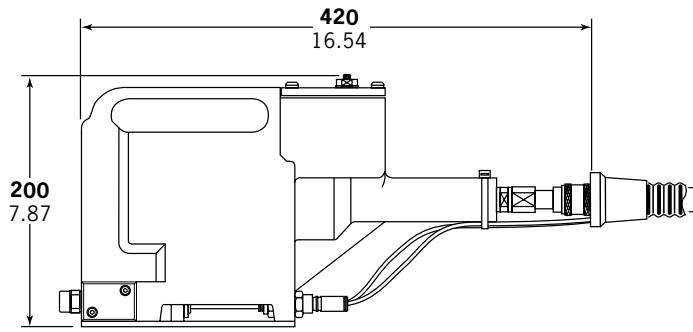
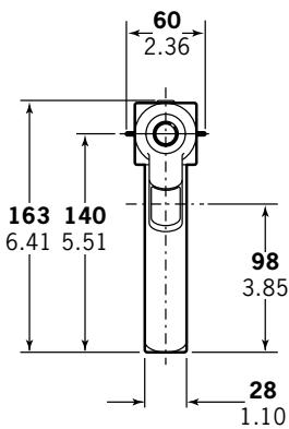
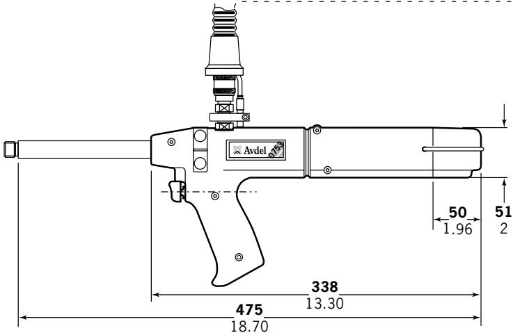
Both models, the 07530 Mkll and 07532 Mkll are hand-held lightweight tools. Their only difference lies in the location of the hose entry. The top entry on the 07532 Mkll tool allows suspension from an added mounting plate, see drawing opposite. Part numbers are shown to order a complete tool including the intensifier and all hoses but no nose equipment.
The pistol number for the 07530 MkII model is 07530-02200 and is 07532-02200 for the 07532 MkII model. See the general assemblies on pages 28-31.
Both models will place the same fasteners and both will place most repetition fasteners, as shown in the table below.
Both models make use of the same nose equipment. Reference must be made to the Nose Equipment section of the manual when selecting compatible components for the type and size of fastener used in your application (see pages 13-21). Nose jaw dimensions are shown on page 14.
| FASTENER NAME | FASTENER SIZE | |||||||||||
| 3/32" | 1/8" | 5/32" | 3/16" | 1/4" | 2.5mm2.8mm | 3mm | 3.5mm | 4mm | 6mm | M2.54-40UNC | M36-32UNC | |
| CHOBERT® | ● | ● | ● | ● | ● | |||||||
| GROVIT® | ● | ● | ● | ● | ||||||||
| AVLUG® | ● | ● | ||||||||||
| BRIV® | ● | ● | ● | ● | ● | |||||||
| RIVSCREW® | ● | ● | ● | ● | ||||||||
| AVTRONIC® | ● | |||||||||||
| AVSERT® | ● | ● | ||||||||||
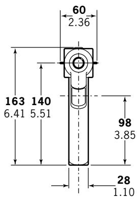
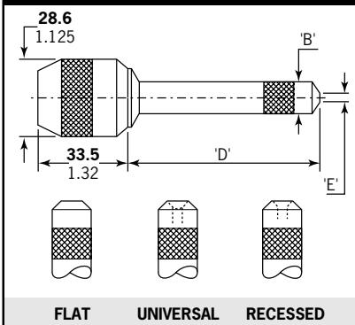
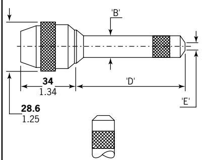
Tool Dimensions - 07530 MkII Model
Part Number 07530-02100
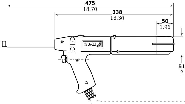
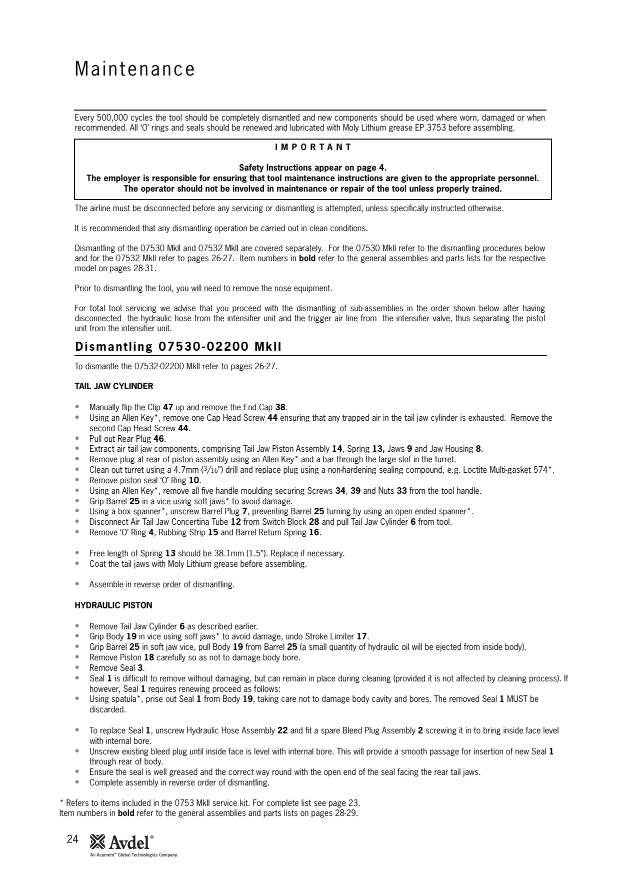
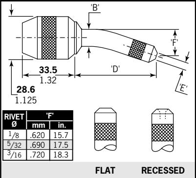
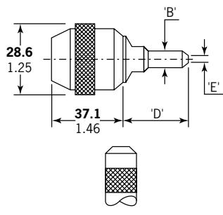
Tool Dimensions - 07532 MkII Model
Part Number 07532-02100
Putting into Service
Air Supply
All tools are operated with compressed air at an optimum pressure of 5.5 bar. We recommend the use of pressure regulators and automatic oiling/filtering systems on the main air supply. To ensure maximum tool life and minimum tool maintenance they should be fitted within 3 metres of the tool (see diagram below).
Air supply hoses should have a minimum working effective pressure rating of 150% of the maximum pressure produced in the system or 10 bar, whichever is the highest. Air hoses should be oil resistant, have an abrasion resistant exterior and should be armoured where operating conditions may result in hoses being damaged. All air supply hoses MUST have a minimum bore diameter of 6.4 millimetres or 1/4 inch.
Read daily servicing details page 22.
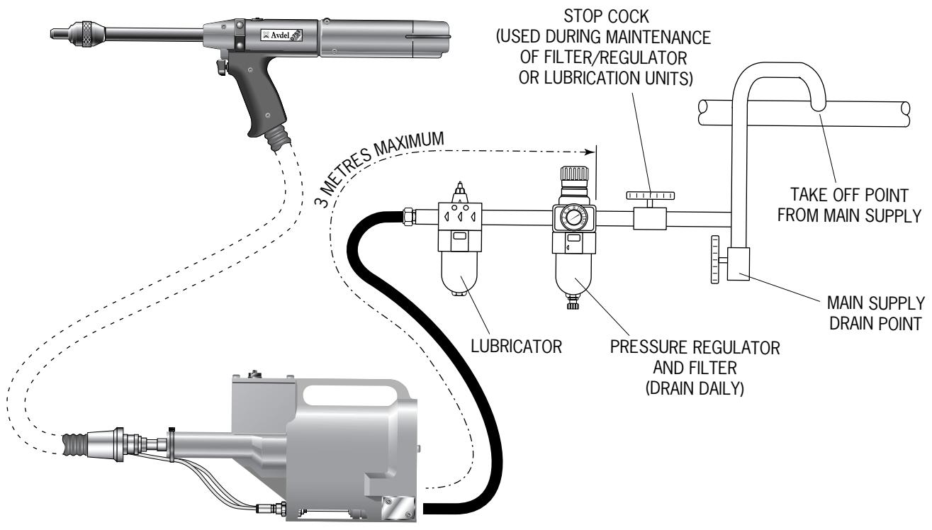
Follow the steps below when connecting the tool to the intensifier and main air supply:
- Push the end of the large hydraulic hose from the tool into the quick release connector on the end of the intensifier.
-
On the front face of the intensifier:
-
Push the blue pneumatic (4mm OD) line into the reducer fitting which is located in the left hand bulkhead connector.
-
Push the black pneumatic (4mm OD) line into the plastic collet of the right hand bulkhead connector.
-
Fit a pneumatic hose between the male connector at the rear of the intensifier and main air supply.
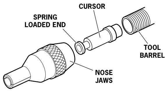
Mechanical Cursor
For reference there are three different mechanical cursor types:
07271-01100
07279-05843
07279-05845
Used for Standard mandrels and 5/32" Disposable mandrels
Used for 1/8 Disposable mandrels
Used for 3/16" Disposable mandrels
The difference in the above assemblies is the internal diameter of the End Plug.
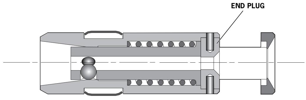
These are colour coded see below:
| MECHANICAL CURSOR PART NO. | END PLUG PART NO. | COLOUR | HOLE DIAMETER (mm) |
| 07271-01100 | 07150-00402 | PLAIN STEEL | 2.7 |
| 07279-05843 | 07159-05844 | GOLD | 2.2 |
| 07279-05845 | 07159-05846 | SILVER | 3.3 |
IMPORTANT
If fitted incorrectly, the cursor will not allow feeding of the fasteners.
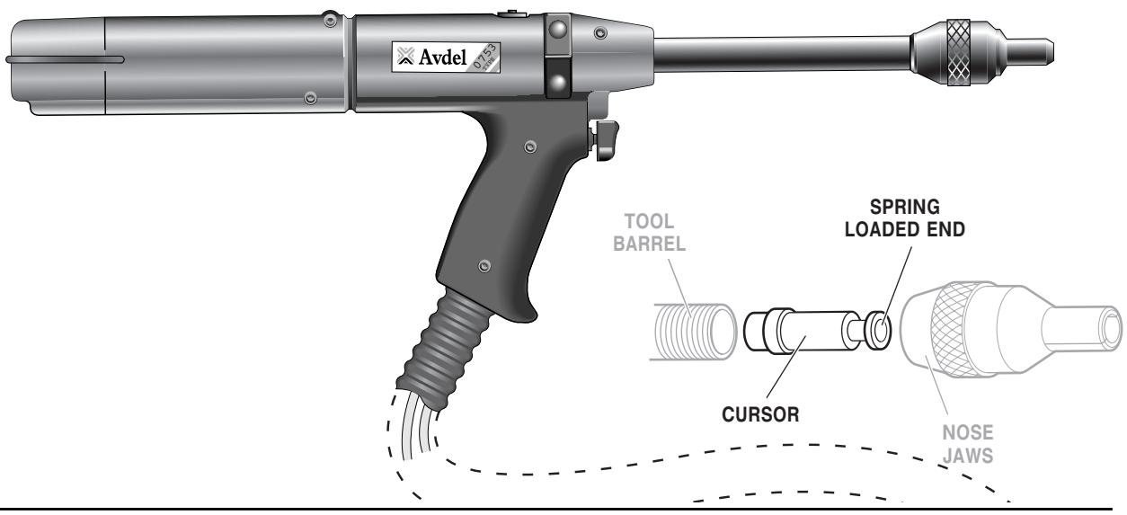
While the cursor will be fitted the correct way round when the tool is supplied, we recommend that you check its orientation before fitting the nose equipment. The sprung loaded, slightly concave, end of the cursor should point towards the front of the tool as shown in the illustration.
When fitted the correct way round, the cursor will easily slide out of the barrel when a mandrel is pushed into its centre then pulled back.
To reverse the orientation of the cursor, follow these steps:
Item numbers in bold refer to the general assembly and parts list for the 07530-02200 MkII type on pages 28-29. For the 07532-02200 MkII type, the procedure is the same but the part numbers must be taken from the general assembly and parts list on pages 30-31.
- Remove the clip 47 and slide off end cap 38.
- Using an Allen Key, remove one cap head screw 44 ensuring that any trapped air is exhausted. remove the second cap head screw 44.
Pull out rear plug 46.
Pull out tail jaw piston assembly 14 together with jaws 9. - Lift out spring 13 and jaw housing 8.
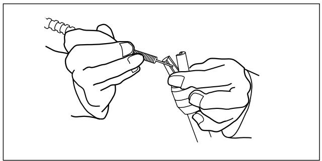
- Insert a mandrel into the hole in the rear end of barrel 25 until it protrudes through the front of the barrel, then pull out the mandrel and cursor together through the front.
Reassemble components in reverse order. - Insert Mechanical Cursor Assembly 5 into the front of the barrel, correct way round.
Loading and Reloading the Tool
IMPORTANT
The procedure for loading the tool and for fitting the nose equipment to the tool is integral.
When ordering a complete tool or system you will normally be supplied with all the nose equipment required for the fastener to be placed.
To identify nose equipment components or to select the correct elements, read the nose equipment section, on pages 13-21.
If you have been supplied with a nose jaw, mandrels and mandrel follower springs proceed with loading the tool and fitting the nose equipment as shown overleaf.
Loading the Tool
- Connect the air supply to the tool.
- Open tail jaws 9 which grip the mandrel, by switching off the tail jaw switch (items 26 and 30).
- Screw selected nose jaws onto barrel 25 of the tool.
n Insert a mandrel into the tail end of the fasteners through the paper pod. - Slide the mandrel follower spring onto the mandrel ensuring correct orientation, as shown in the table on page 12.
Gripping the tail end of the mandrel, tear off the paper pod from around the fasteners. - Open the nose jaws either by rotating the outer ring on Cam operated jaws or by pushing outwards on the jaw ends, as illustrated below left.
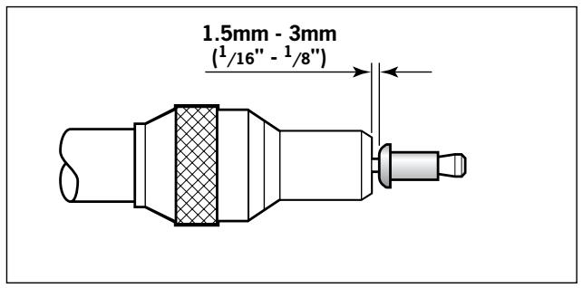
- Insert the previously assembled mandrel, mandrel follower spring and fasteners into the nose jaws until the first fastener to be placed is protruding from the nose jaw.
- Close the nose jaws and adjust so that the first fastener protrudes by 1.5mm - 3mm ( 1/16'' to 1/8'' ), as shown in the illustration below right.
- Close the tail jaws to ensure the mandrel is gripped, by switching on the tail jaw switch (items 26 and 30).
Reloading the Tool
- Open tail jaws 9 of tool.
- Open the nose jaws and pull the empty mandrel and mandrel follower spring out of the tool.
- Reload the tool by following the above instructions, starting at stage n.
Operating Procedure
IMPORTANT
You must check that the cursor orientation and the nose equipment are correct before attempting to operate the tool.
- Push the fastener, protruding from the nose jaws, fully into the application holes ensuring that the tool is held square.
Operate the trigger without releasing - the mandrel head is pulled through the fastener, forming the fastener into the application. - Remove the tool.
- Release the trigger. The next fastener will be automatically presented through the nose jaws, ready for placing.
Item numbers in bold refer to the general assembly and parts list for the 07530-02200 MkII type on pages 28-29. For the 07532-02200 MkII type, the procedure is the same but the part numbers must be taken from the general assembly and parts list on pages 30-31.
| MANDREL FOLLOWER SPRINGS IDENTIFICATION AND ORIENTATION | ||||
| FASTENER | NOSE JAW(SEE NOSE EQUIPMENT SECTION) | MANDRELSIZE | MANDREL/MANDREL FOLLOWER SPRINGAND FASTENER ASSEMBLY | |
| NAME | SIZE | |||
| BRIV® | 3/32" | STANDARD TAPERED | ALL | MANDREL FOLLOWER SPRINGMANDREL HEADFERRULESPRINGMANDREL |
| 3/32" | LIMITED ACCESS &LIMITED ACCESS CAM OPERATED | ALL | - - - - - - - - - - - - - - - - - - - - - - - - - - - - - - - - - - - - - - - - - - - - - - - - - - - - - - - - - - - - - - - - - - - - - - - - - - - - - - - - - - - - - - - - - - - - - - - - - - - - - | |
| 1/8" | ALL | ALL | - - - - - - - - - - - - - - - - - - - - - - - - - - - - - - - - - - - - - - - - - - - - - - - - - - - - - - - - - - - - - - - - - - - - - - - - - - - - - - - - - - - - - - - - - - - - - - - - | |
| 5/32" | ALL | ALL | - - - - - - - - - - - - - - - - - - - - - - - - - - - - - - - - - - - - - - - - - - - - - - - - - - - - - - - - - - - - - - - - - - - - - - - - - - - - - - - - - - - - - - - - - - - - - | |
| 3/16" | ALL | ALL | - - - - - - - - - - - - - - - - - - - - - - - - - - - - - - - - - - - - - - - - - - - - - - - - - - - - - - - - - - - - - - - - - - - - - - - - - - - - - - - - - - - - - - - - - - - - - 0.75mm | |
| 6mm | STANDARD | ALLEXCEPT 3rdOVERSIZE | - - - - - - - - - - - - - - - - - - - - - - - - - - - - - - - - - - - - - - - - - - - - - - - - - - - - - - - - - - - - - - - - - - - - - - - - - - - - - - - - - - - - - - - - - - - - - - - - - - | |
| CHOBERT®AVLUG®GROVIT® | 3/32" | ALL EXCEPTSTANDARD TAPERED,LIMITED ACCESS | ALL | - - - - - - - - - - - - - - - - - - - - - - - - - - - - - - - - - - - - - - - - - - - - - - - - - - - - - - - - - - - - - - - - - - - - - - - - - - - - - - - - - - - - - - - - - - - - - - - - 0.75mm |
| 3/32" | STANDARD TAPERED,LIMITED ACCESS | ALL | - - - - - - - - - - - - - - - - - - - - - - - - - - - - - - - - - - - - - - - - - - - - - - - - - - - - - - - - - - - - - - - - - - - - - - - - - - - - - - - - - - - - - - - | |
| 1/8" | ALL | ALL | -- - - - - - - - - - - - - - - - - - - - - - - - - - - - - - - - - - - - - - - - - - - - - - - - - - - - - - - - - - - - - - - - - - - - - - - - | |
| CHOBERT®GROVIT® | 5/32" | ALL | ALLEXCEPT3rdOVERSIZE | - - - - - - - - - - - - - - - - - - - - - - - - - - - - - - - - - - - - - - - - - - - - - - - - - - - - - - - - - - - - - - - - - - - - - - - - - - - - - - - - - - |
| 5/32" | ALL | 3rdOVERSIZE | - - - - - - - - - - - - - - - - - - - - - - - - - - - - - - - - - - - - | |
| 3/16" | ALL | ALLEXCEPT2ndOVERSIZE | - - - - - - - - - - - - - - - - - - - - - - - - - - - - | |
| 3/16" | ALL | 2ndOVERSIZE | - - - - - - - - - - - - - - - - - - | |
| CHOBERT® | 1/4" | ALL | ALL | - - - - - - - - - - - - - |
| RIVSCREW® | 2.8mm | ALL | ALL | - - - - - - - - - - - |
| 3mm | ||||
| 3.5mm | ALL | ALL | - - - - - - - - - - | |
| 4mm | ||||
| AVSERT® | 2.5mm | ALL | ALL | - - - - - - - - |
| 4 x 40UNC | ||||
| 3mm | ALL | ALL | - - - - - - | |
| 6 x 32UNC | ||||
| AVTRONIC® | 2.5mm | ALL | ALL | - - - - - |
| 2.8mm | ALL EXCEPTLIMITED ACCESS | ALL | - - - - - | |
| 2.8mm | LIMITED ACCESS | ALL | - - - - - | |
On speed fastening tools such as 0753 MkII type, the nose equipment always consists of three elements: a nose jaw, a mandrel and a mandrel follower spring. All three items are matched to the fastener being placed and to the hole size in the application.
IMPORTANT
To avoid complete dismantling of the tool it is essential to check the orientation of the cursor before fitting the nose equipment to the tool. See 'CURSOR' section on page 10.
It is essential that the correct nose equipment is fitted to the tool to ensure both effective placing of the fastener and SAFE operation of the tool. READ THE SAFETY INSTRUCTIONS page 4 carefully.
To identify the correct combination of nose equipment to fit your tool first select a nose jaw by reading the section below then read the mandrel section to select part numbers both for the mandrel itself and for the mandrel follower spring. Mandrels and mandrel follower springs are illustrated on page 12.
To fit the nose equipment, follow the 'Loading the Tool' procedure page 11.
Nose Jaws
IMPORTANT
The wrong nose jaw could result in an incorrectly placed fastener or incorrect clench.
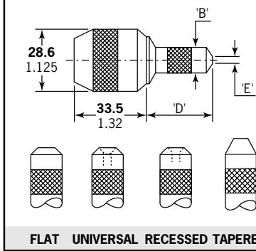
Nose Jaws can be categorised into 7 different basic shapes as illustrated opposite, even though internal dimensions will vary according to the fastener it is intended for. Exact dimensions referring to the letters in the illustrations opposite are indicated in the 'Nose Jaw Selection Tables' on pages 15-16.
For a particular shape, there may be several options of end form giving access benefits or fastener placing enhancement.
Flat
Normal end form of all nose jaws.
- Suitable on all applications with no access restrictions.
Universal
Designed for use with universal head Chobert® fasteners.
- Can also be used with Briv® fasteners to obtain the highest possible clench. Note this reduces the maximum grip range of the Briv® fastener by approximately 0.015" (0.4mm).
Recessed
For use with Briv® fasteners ONLY.
It gives a higher clench than a flat end form but less than a universal end form, with no reduction of the grip range of the fastener.
Tapered
Available as shown in the 'Nose Jaw Selection Tables'.
- Allows greater accessibility than a flat end form and places the same range.
Head Forming
For use with Rivscrew® fasteners ONLY.
- Deforms the head of the fastener to achieve good clench.
List the name, size and material of the fastener to be placed.
- Look for this fastener in the first column of the nose jaw selection tables on page 15 if you use imperial measurements and on page 16 if you use metric units.
- Looking right across the table, take note of which nose jaws are available. ONLY those shown are available.
- Select which is most suitable for your application by referring to the respective nose jaw drawing. If your application has no access restriction, you should select the standard shape with a flat end form with or without a cam.
STANDARD
Available in 4 different end forms to place all fasteners (except Rivscrew). Suitable on applications with no or little access restriction.
LONG
Available to place most of the fasteners. Allows more penetration into applications with no other access restriction.
LONG CURVED
Available as shown in NOSE JAW SELECTION TABLE.
Allows more penetration into applications with restricted access.
Mandrels must be curved by hand to follow the shape of the jaw.
LIMITED ACCESS
Available as shown in NOSE JAW SELECTION TABLE. Allows access into very restrictive applications.
STANDARD CAM OPERATED
FLAT
HEAD FORMING (HF)
LONG CAM OPERATED
FLAT
LIMITED ACCESS CAM OPERATED
FLAT
Available as shown in NOSE JAW SELECTION TABLE overleaf. Equivalent functions to the Standard and Limited Access above with the addition of a cam to ease and speed up the nose jaw opening thus the pod reloading procedure.
Dimensions shown in bold are millimetres. Other dimensions are in inches.
Nose Jaw Selection - Imperial
The 'REF N' column cross references with the 'REF N' columns in the mandrel section. It identifies both the mandrel and mandrel follower spring required for a particular nose jaw with a specific fastener.
| FASTENER | REF. N° | NOSE JAW | REF. N° | NOSE JAW | ||||||
| TYPE AND END FORM | PART N° | DIMENSIONS | TYPE AND END FORM | PART N° | DIMENSIONS | |||||
| 'B' | 'D' | 'E' | 'B' | 'D' | ||||||
| 3/32" CHOBERT® & GROVIT | 1 | STANDARD - FLAT | 07150-03003 | .36 | 1.30 | .16 | 1 | # STANDARD - UNIVERSAL | 07150-03203 | .36 |
| 1 | STD. CAM OPERATED - FLAT | 07170-04500 | .36 | 1.30 | .16 | 1 | LTD. ACCESS CAM OPERATED | 07177-03003 | .20 | |
| 2 | STANDARD - TAPERED | 07170-03103 | .36 | 1.30 | .16 | 3 | LIMITED ACCESS | 07274-01000 | .22 | |
| 4 | LONG - FLAT | 07150-04003 | .41 | 2.30 | .16 | 4 | LONG CURVED - FLAT | 07150-05003 | .41 | |
| 1/8" CHOBERT® & GROVIT | 5 | STANDARD - FLAT | 07150-03004 | .41 | 1.18 | .20 | 5 | # STANDARD - UNIVERSAL | 07150-03204 | .41 |
| 5 | STANDARD - TAPERED | 07170-03104 | .41 | 1.19 | .20 | 5 | STD. CAM OPERATED - FLAT | 07170-04600 | .41 | |
| 6 | LONG - FLAT | 07150-04004 | .41 | 2.18 | .20 | 6 | # LONG - UNIVERSAL | 07150-04204 | .41 | |
| 6 | LONG CURVED - FLAT | 07150-05004 | .41 | 2.12 | .20 | 6 | LONG CAM OPERATED - FLAT | 07170-05000 | .41 | |
| 5/32" CHOBERT® & GROVIT | 7 | STANDARD - FLAT | 07150-03005 | .48 | 1.30 | .24 | 7 | # STANDARD - UNIVERSAL | 07150-03205 | .48 |
| 7 | STANDARD - TAPERED | 07150-03105 | .44 | 1.30 | .24 | 7 | STD. CAM OPERATED - FLAT | 07170-04700 | .48 | |
| 8 | LONG - FLAT | 07150-04005 | .48 | 2.30 | .24 | 8 | # LONG - UNIVERSAL | 07150-04205 | .48 | |
| 8 | LONG CURVED - FLAT | 07150-05005 | .48 | 2.23 | .24 | 8 | LONG CAM OPERATED - FLAT | 07170-05100 | .48 | |
| 3/16" CHOBERT® & GROVIT | 9 | STANDARD - FLAT | 07150-03006 | .56 | 1.18 | .33 | 9 | # STANDARD - UNIVERSAL | 07150-03206 | .56 |
| 9 | STANDARD - TAPERED | 07150-03106 | .56 | 1.18 | .33 | 9 | STD. CAM OPERATED - FLAT | 07170-04800 | .56 | |
| 10 | LONG - FLAT | 07150-04006 | .56 | 2.30 | .33 | 10 | # LONG - UNIVERSAL | 07150-04206 | .56 | |
| 10 | LONG CURVED - FLAT | 07150-05006 | .56 | 2.21 | .33 | 10 | LONG CAM OPERATED - FLAT | 07170-05200 | .56 | |
| 1/4" CHOBERT® | 11 | STANDARD - FLAT | 07150-03008 | .64 | 1.18 | .39 | 11 | STD. CAM OPERATED - FLAT | 07170-04900 | .64 |
| 12 | LONG - FLAT | 07150-04008 | .64 | 2.18 | .39 | 12 | LONG CAM OPERATED - FLAT | 07170-05300 | .64 | |
| 3/32" BRIV® Brass only | 13 | STANDARD - TAPERED | 07170-03103 | .36 | 1.30 | .15 | 14 | LTD. ACCESS CAM OPERATED | 07177-03003 | .20 |
| 14 | LIMITED ACCESS | 07274-01000 | .22 | 1.07 | .16 | - | - | - | - | |
| 1/8" BRIV® Al. Alloy, Brass, Steel | 15 | STANDARD - FLAT | 07150-03004 | .41 | 1.18 | .20 | 15 | STANDARD - RECESSSED | 07170-03004 | .41 |
| 15 | STANDARD - TAPERED | 07170-03104 | .41 | 1.19 | .20 | 16 | LONG - FLAT | 07150-04004 | .41 | |
| 16 | LONG - RECESSSED | 07170-03204 | .41 | 2.18 | .30 | 16 | LONG CURVED - FLAT | 07150-05004 | .41 | |
| 16 | LONG CURVED - RECESSSED | 07170-03304 | .41 | 2.12 | .30 | - | - | - | - | |
| 5/32" BRIV® Al. Alloy, Brass, Steel | 17 | STANDARD - FLAT | 07150-03005 | .48 | 1.30 | .24 | 17 | STANDARD - RECESSSED | 07170-03005 | .48 |
| 18 | LONG - FLAT | 07150-04005 | .48 | 2.30 | .24 | 18 | LONG - RECESSSED | 07170-03205 | .48 | |
| 18 | LONG CURVED - FLAT | 07150-05005 | .48 | 2.23 | .24 | 18 | LONG CURVED - RECESSSED | 07170-03305 | .48 | |
| 5/32" BRIV® St. Steel only | 19 | STANDARD - FLAT | 07150-03005 | .48 | 1.30 | .24 | 19 | STANDARD - RECESSSED | 07170-03005 | .48 |
| 20 | LONG - FLAT | 07150-04005 | .48 | 2.30 | .24 | 20 | LONG - RECESSSED | 07170-03205 | .48 | |
| 20 | LONG CURVED - FLAT | 07150-05005 | .48 | 2.23 | .24 | 20 | LONG CURVED - RECESSSED | 07170-03305 | .48 | |
| 3/16" BRIV® Al. Alloy, Brass, Steel | 21 | STANDARD - FLAT | 07150-03006 | .56 | 1.18 | .33 | 21 | STANDARD - RECESSSED | 07170-03006 | .56 |
| 22 | LONG - FLAT | 07150-04006 | .56 | 2.30 | .33 | 22 | LONG - RECESSSED | 07170-03206 | .56 | |
| 22 | LONG CURVED - FLAT | 07150-05006 | .56 | 2.21 | .33 | 22 | LONG CURVED - RECESSSED | 07170-03306 | .56 | |
| 3/16" BRIV® St. Steel only | 23 | STANDARD - FLAT | 07150-03006 | .56 | 1.18 | .33 | 23 | STANDARD - RECESSSED | 07170-03006 | .56 |
| 24 | LONG - FLAT | 07150-04006 | .56 | 2.30 | .33 | 24 | LONG - RECESSSED | 07170-03206 | .56 | |
| 24 | LONG CURVED - FLAT | 07150-05006 | .56 | 2.21 | .33 | 24 | LONG CURVED - RECESSSED | 07170-03306 | .56 | |
| 6mm BRIV® Al. Alloy, Steel | 25 | STD. CAM OPERATED | 07170-05600 | .64 | 1.21 | .52 | 25 | STANDARD - FLAT | 07170-05800 | .64 |
| 26 | LONG CAM OPERATED | 07170-05700 | .64 | 2.19 | .52 | 26 | LONG - FLAT | 07170-05900 | .64 | |
| 3/32" AVLUG® | 27 | STANDARD - FLAT | 07150-03003 | .36 | 1.30 | .16 | 27 | STANDARD - TAPERED | 07150-03103 | .36 |
| 27 | STD. CAM OPERATED - FLAT | 07170-04500 | .36 | 1.30 | .16 | 28 | LONG - FLAT | 07150-04003 | .41 | |
| 28 | LONG CURVED - FLAT | 07150-05003 | .41 | 2.28 | .16 | - | - | - | - | |
| 1/8" AVLUG® | 29 | STANDARD - FLAT | 07150-03004 | .41 | 1.18 | .20 | 29 | STANDARD - TAPERED | 07170-03104 | .41 |
| 29 | STD. CAM OPERATED - FLAT | 07170-04600 | .41 | 1.18 | .20 | 30 | LONG - FLAT | 07150-04004 | .41 | |
| 30 | LONG CURVED - FLAT | 07150-05004 | .41 | 2.12 | .20 | 30 | LONG CAM OPERATED - FLAT | 07170-05000 | .41 | |
| 2.5mm, 4-40 UNC AVLSET® | 31 | STANDARD - FLAT | 07150-03003 | .36 | 1.30 | .16 | - | - | - | - |
| 3.0mm, 6-32 UNC AVLSET® | 32 | STANDARD - FLAT | 07150-03004 | .41 | 1.18 | .20 | 32 | STD. CAM OPERATED - FLAT | 07170-04600 | .41 |
| 33 | STANDARD - FLAT | 07150-03003 | .36 | 1.30 | .16 | 33 | LTD. ACCESS CAM OPERATED | 07271-08000 | .41 | |
| 34 | LONG - FLAT | 07150-04003 | .41 | 2.30 | .16 | - | - | - | - | |
| 2.8mm AVTRONIC® | 35 | STANDARD - FLAT | 07271-05600 | .36 | 1.30 | .16 | 36 | LTD. ACCESS CAM OPERATED | 07271-08100 | .40 |
| 37 | STANDARD - FLAT | 07271-05900 | .41 | 2.30 | .16 | - | - | - | - | |
| 2.8mm RIVSCREW® | 38 | STD. CAM OPERATED - HF | 07271-03000 | .41 | 1.18 | .24 | - | - | - | - |
| 39 | STD. CAM OPERATED - HF | 07271-03000 | .41 | 1.18 | .24 | - | - | - | - | |
| 40 | STD. CAM OPERATED - HF | 07271-03500 | .41 | 1.18 | .24 | - | - | - | - | |
| 41 | STD. CAM OPERATED - HF | 07271-04000 | .41 | 1.18 | .25 | - | - | - | - | |
These nose jaws are suitable for placing Chobert® rivets with a Universal Head Form. When used on the equivalent size of Briv®, the highest possible clench is achieved. Note when using Briv® fasteners, the maximum grip is reduced by approximately 0.015" (0.4mm). possible clench is achieved. Note that when using Briv fasteners, the maximum grip is reduced by approximately 0.015" (0.4 mm).
| FASTENER | REF. N° | NOSE JAW | REF. N° | NOSE JAW | ||||||
| TYPE AND END FORM | PART N° | DIMENSIONS | TYPE AND END FORM | PART N° | DIMENSIONS | |||||
| 'B' | 'D' | 'E' | 'B' | 'D' | ||||||
| 3/32" CHOBERT® & GROVIT | 1 | STANDARD - FLAT | 07150-03003 | 9.14 | 33.02 | 4.06 | 1 | # STANDARD - UNIVERSAL | 07150-03203 | 9.14 |
| 1 | STD. CAM OPERATED - FLAT | 07170-04500 | 9.14 | 33.02 | 4.06 | 1 | LTD. ACCESS CAM OPERATED | 07177-03003 | 5.08 | |
| 2 | STANDARD - TAPERED | 07170-03103 | 9.14 | 33.02 | 4.06 | 3 | LIMITED ACCESS | 07274-01000 | 5.59 | |
| 4 | LONG - FLAT | 07150-04003 | 10.41 | 58.42 | 4.06 | 4 | LONG CURVED - FLAT | 07150-05003 | 10.41 | |
| 1/8" CHOBERT® & GROVIT | 5 | STANDARD - FLAT | 07150-03004 | 10.41 | 29.97 | 5.08 | 5 | # STANDARD - UNIVERSAL | 07150-03204 | 10.41 |
| 5 | STANDARD - TAPERED | 07170-03104 | 10.41 | 30.23 | 5.08 | 5 | STD. CAM OPERATED - FLAT | 07170-04600 | 10.41 | |
| 6 | LONG - FLAT | 07150-04004 | 10.41 | 55.37 | 5.08 | 6 | # LONG - UNIVERSAL | 07150-04204 | 10.41 | |
| 6 | LONG CURVED - FLAT | 07150-05004 | 10.41 | 53.85 | 5.08 | 6 | LONG CAM OPERATED - FLAT | 07170-05000 | 10.41 | |
| 5/32" CHOBERT® & GROVIT | 7 | STANDARD - FLAT | 07150-03005 | 12.19 | 33.02 | 6.10 | 7 | # STANDARD - UNIVERSAL | 07150-03205 | 12.19 |
| 7 | STANDARD - TAPERED | 07150-03105 | 11.18 | 33.02 | 6.10 | 7 | STD. CAM OPERATED - FLAT | 07170-04700 | 12.19 | |
| 8 | LONG - FLAT | 07150-04005 | 12.19 | 58.42 | 6.10 | 8 | # LONG - UNIVERSAL | 07150-04205 | 12.19 | |
| 8 | LONG CURVED - FLAT | 07150-05005 | 12.19 | 56.64 | 6.10 | 8 | LONG CAM OPERATED - FLAT | 07170-05100 | 12.19 | |
| 3/16" CHOBERT® & GROVIT | 9 | STANDARD - FLAT | 07150-03006 | 14.22 | 29.97 | 8.38 | 9 | # STANDARD - UNIVERSAL | 07150-03206 | 14.22 |
| 9 | STANDARD - TAPERED | 07150-03106 | 14.22 | 29.97 | 8.38 | 9 | STD. CAM OPERATED - FLAT | 07170-04800 | 14.22 | |
| 10 | LONG - FLAT | 07150-04006 | 14.22 | 58.42 | 8.38 | 10 | # LONG - UNIVERSAL | 07150-04206 | 14.22 | |
| 10 | LONG CURVED - FLAT | 07150-05006 | 14.22 | 56.13 | 8.38 | 10 | LONG CAM OPERATED - FLAT | 07170-05200 | 14.22 | |
| 1/4" CHOBERT® | 11 | STANDARD - FLAT | 07150-03008 | 16.26 | 29.97 | 9.91 | 11 | STD. CAM OPERATED - FLAT | 07170-04900 | 16.26 |
| 12 | LONG - FLAT | 07150-04008 | 16.26 | 55.37 | 9.91 | 12 | LONG CAM OPERATED - FLAT | 07170-05300 | 16.26 | |
| 3/32" BRIV® Brass only | 13 | STANDARD - TAPERED | 07170-03103 | 9.14 | 33.02 | 3.81 | 14 | LTD. ACCESS CAM OPERATED | 07177-03003 | 5.08 |
| 14 | LIMITED ACCESS | 07274-01000 | 5.59 | 27.18 | 4.06 | - | - | - | - | |
| 1/8" BRIV® Al. Alloy, Brass, Steel | 15 | STANDARD - FLAT | 07150-03004 | 10.41 | 29.97 | 5.08 | 15 | STANDARD - RECESSSED | 07170-03004 | 10.41 |
| 15 | STANDARD - TAPERED | 07170-03104 | 10.41 | 30.23 | 5.08 | 16 | LONG - FLAT | 07150-04004 | 10.41 | |
| 16 | LONG - RECESSSED | 07170-03204 | 10.41 | 55.37 | 7.62 | 16 | LONG CURVED - FLAT | 07150-05004 | 10.41 | |
| 16 | LONG CURVED - RECESSSED | 07170-03304 | 10.41 | 53.85 | 7.62 | - | - | - | - | |
| 5/32" BRIV® Al. Alloy, Brass, Steel | 17 | STANDARD - FLAT | 07150-03005 | 12.19 | 33.02 | 6.10 | 17 | STANDARD - RECESSSED | 07170-03005 | 12.19 |
| 18 | LONG - FLAT | 07150-04005 | 12.19 | 58.42 | 6.10 | 18 | LONG - RECESSSED | 07170-03205 | 12.19 | |
| 18 | LONG CURVED - FLAT | 07150-05005 | 12.19 | 56.64 | 6.10 | 18 | LONG CURVED - RECESSSED | 07170-03305 | 12.19 | |
| 5/32" BRIV® St. Steel only | 19 | STANDARD - FLAT | 07150-03005 | 12.19 | 33.02 | 6.10 | 19 | STANDARD - RECESSSED | 07170-03005 | 12.19 |
| 20 | LONG - FLAT | 07150-04005 | 12.19 | 58.42 | 6.10 | 20 | LONG - RECESSSED | 07170-03205 | 12.19 | |
| 20 | LONG CURVED - FLAT | 07150-05005 | 12.19 | 56.64 | 6.10 | 20 | LONG CURVED - RECESSSED | 07170-03305 | 12.19 | |
| 3/16" BRIV® Al. Alloy, Brass, Steel | 21 | STANDARD - FLAT | 07150-03006 | 14.22 | 29.97 | 8.38 | 21 | STANDARD - RECESSSED | 07170-03006 | 14.22 |
| 22 | LONG - FLAT | 07150-04006 | 14.22 | 58.42 | 8.38 | 22 | LONG - RECESSSED | 07170-03206 | 14.22 | |
| 22 | LONG CURVED - FLAT | 07150-05006 | 14.22 | 56.13 | 8.38 | 22 | LONG CURVED - RECESSSED | 07170-03306 | 14.22 | |
| 3/16" BRIV® St. Steel only | 23 | STANDARD - FLAT | 07150-03006 | 14.22 | 29.97 | 8.38 | 23 | STANDARD - RECESSSED | 07170-03006 | 14.22 |
| 24 | LONG - FLAT | 07150-04006 | 14.22 | 58.42 | 8.38 | 24 | LONG - RECESSSED | 07170-03206 | 14.22 | |
| 24 | LONG CURVED - FLAT | 07150-05006 | 14.22 | 56.13 | 8.38 | 24 | LONG CURVED - RECESSSED | 07170-03306 | 14.22 | |
| 6mm BRIV® Al. Alloy, Steel | 25 | STD. CAM OPERATED | 07170-05600 | 16.33 | 30.65 | 13.14 | 25 | STANDARD - FLAT | 07170-05800 | 16.33 |
| 26 | LONG CAM OPERATED | 07170-05700 | 16.33 | 55.65 | 13.14 | 26 | LONG - FLAT | 07170-05900 | 16.33 | |
| 3/32" AVLUG® | 27 | STANDARD - FLAT | 07150-03003 | 9.14 | 33.02 | 4.06 | 27 | STANDARD - TAPERED | 07150-03103 | 9.14 |
| 27 | STD. CAM OPERATED - FLAT | 07170-04500 | 9.14 | 33.02 | 4.06 | 28 | LONG - FLAT | 07150-04003 | 10.41 | |
| 28 | LONG CURVED - FLAT | 07150-05003 | 10.41 | 57.91 | 4.06 | - | - | - | - | |
| 1/8" AVLUG® | 29 | STANDARD - FLAT | 07150-03004 | 10.41 | 29.97 | 5.08 | 29 | STANDARD - TAPERED | 07170-03104 | 10.41 |
| 29 | STD. CAM OPERATED - FLAT | 07170-04600 | 10.41 | 29.97 | 5.08 | 30 | LONG - FLAT | 07150-04004 | 10.41 | |
| 30 | LONG CURVED - FLAT | 07150-05004 | 10.41 | 53.85 | 5.08 | 30 | LONG CAM OPERATED - FLAT | 07170-05000 | 10.41 | |
| 2.5mm, 4-40 UNC AVSERT® | 31 | STANDARD - FLAT | 07150-03003 | 9.14 | 33.02 | 4.06 | - | - | - | - |
| 3.0mm, 6-32 UNC AVSERT® | 32 | STANDARD - FLAT | 07150-03004 | 10.41 | 29.97 | 5.08 | 32 | STD. CAM OPERATED - FLAT | 07170-04600 | 10.41 |
| 33 | STANDARD - FLAT | 07150-03003 | 9.14 | 33.02 | 4.06 | 33 | LTD. ACCESS CAM OPERATED | 07271-08000 | 10.41 | |
| 34 | LONG - FLAT | 07150-04003 | 10.41 | 58.42 | 4.06 | - | - | - | - | |
| 2.8mm AVTRONIC® | 35 | STANDARD - FLAT | 07271-05600 | 9.14 | 33.02 | 4.06 | 36 | LTD. ACCESS CAM OPERATED | 07271-08100 | 10.16 |
| 37 | LONG - FLAT | 07271-05900 | 10.41 | 58.42 | 4.06 | - | - | - | - | |
| 2.8mm RIVSCREW® | 38 | STD. CAM OPERATED - HF | 07271-03000 | 10.41 | 29.97 | 6.10 | - | - | - | - |
| 39 | STD. CAM OPERATED - HF | 07271-03000 | 10.41 | 29.97 | 6.10 | - | - | - | - | |
| 40 | STD. CAM OPERATED - HF | 07271-03500 | 10.41 | 29.97 | 6.10 | - | - | - | - | |
| 41 | STD. CAM OPERATED - HF | 07271-04000 | 10.41 | 29.97 | 6.35 | - | - | - | - | |
These nose jaws are suitable for placing Chobert® rivets with a Universal Head Form. When used on the equivalent size of Briv®, the highest possible clench is achieved. Note that when using Briv® fasteners, the maximum grip is reduced by approximately 0.015" (0.4mm). Possible clench is achieved. Note that when using Briv fasteners, the maximum grip is reduced by approximately 0.015" (0.4 mm).
Mandrels and Mandrel Follower Springs
Mandrels and mandrel follower springs, illustrated on page 12 need to be selected to suit the fastener type and size as well as the size of the hole in the application. Use of the wrong mandrel could increase the risk of breakage and the wear of the mandrel head. Feeding problems could occur if the wrong mandrel follower spring is used.
IMPORTANT
READ THE SAFETY INSTRUCTIONS page 4 carefully.
While a small amount of wear and marking will naturally occur through normal and correct use of mandrels, they must be regularly examined for excessive wear and marking, with particular attention to the head diameter, the tail jaw gripping area of the shank or heavy pitting of the shank and any mandrel distortion. Mandrels which fail during use could forcibly exit the tool. It is the customer's responsibility to ensure that mandrels are replaced before any excessive levels of wear and always before the maximum recommended number of placings. Contact your Avdel representative who will let you know what that figure is by measuring the broach load of your application with our calibrated measuring tool. These tools can also be purchased under part number 07900-09080, supplied with all necessary information for testing.
Chobert® and Grovit® - Imperial
For mandrel or mandrel follower spring selection, follow instructions on page 19.
| FASTENER | REF. N° | HOLE SIZE | STANDARD MANDREL - GREEN | HOLE SIZE | 1ST OVERSIZE MANDREL - YELLOW | SPRING PART N° | ||||||||
| HEAD Ø | MANDREL PART N° | P MAX. | # S/R MANDREL PART N° | P MAX. | HEAD Ø | MANDREL PART N° | P MAX. | # S/R MANDREL PART N° | P MAX. | |||||
| 3/32" CHOBERT® & GROVIT® | 1 | AS REC. | .0725 | 07150-06003 | .166 | 07150-08003 | .071 | +.0015 | .074 | 07150-06303 | .174 | - | - | 07150-06803 |
| 1 | - | - | - | - | - | - | +.0035 | .076 | - | - | 07150-08103 | .078 | 07150-06803 | |
| 2 | AS REC. | .0725 | 07150-06003 | .166 | 07150-08003 | .071 | +.0015 | .074 | 07150-06303 | .174 | - | - | 07170-06873 | |
| 2 | - | - | - | - | - | - | +.0035 | .076 | - | - | 07150-08103 | .078 | 07170-06873 | |
| 3 | AS REC. | .0725 | 07150-06003 | .166 | 07150-08003 | .071 | +.0015 | .074 | 07150-06303 | .174 | - | - | 07170-06903 | |
| 3 | - | - | - | - | - | - | +.0035 | .076 | - | - | 07150-08103 | .078 | 07170-06903 | |
| 4 | AS REC. | .0725 | 07150-07003 | .166 | 07150-09003 | .071 | +.0035 | .076 | - | - | 07150-09103 | .078 | 07150-07803 | |
| 1/8" CHOBERT® & GROVIT® | 5 | AS REC. | .088 | 07150-06004 | .216 | 07150-08004 | .090 | +.004 | .092 | 07150-06104 | .237 | 07150-08104 | .098 | 07150-06804 |
| 6 | AS REC. | .088 | 07150-07004 | .216 | 07150-09004 | .090 | +.004 | .092 | 07150-07104 | .237 | 07150-09104 | .098 | 07150-07804 | |
| 5/32" CHOBERT® & GROVIT® | 7 | AS REC. | .107 | 07150-06005 | .244 | 07150-08005 | .100 | +.008 | .115 | 07150-06105 | .284 | 07150-08105 | .116 | 07170-06875 |
| 7 | - | - | - | - | - | - | - | - | - | - | - | - | - | |
| 8 | AS REC. | .107 | 07150-07005 | .244 | 07150-09005 | .100 | +.008 | .115 | 07150-07105 | .284 | 07150-09105 | .116 | 07170-07875 | |
| 8 | - | - | - | - | - | - | - | - | - | - | - | - | - | |
| 3/16" CHOBERT® & GROVIT® | 9 | AS REC. | .132 | 07150-06006 | .247 | 07150-08006 | .102 | +.014 | .146 | 07150-06106 | .320 | 07150-08106 | .130 | 07170-06876 |
| 9 | - | - | - | - | - | - | - | - | - | - | - | - | - | |
| 10 | AS REC. | .132 | 07150-07006 | .247 | 07150-09006 | .102 | +.014 | .146 | 07150-07106 | .320 | 07150-09106 | .130 | 07170-07876 | |
| 10 | - | - | - | - | - | - | - | - | - | - | - | - | - | |
| 1/4" CHOBERT® | 11 | AS REC. | .184 | 07150-06008 | .268 | 07150-08008 | .110 | +.012 | .196 | 07150-06108 | .330 | 07150-08108 | .134 | 07150-06808 |
| 12 | AS REC. | .184 | 07150-07008 | .268 | 07150-09008 | .110 | +.012 | .196 | 07150-07108 | .330 | 07150-09108 | .134 | 07150-07808 | |
| FASTENER | REF. N° | HOLE SIZE | 2ND OVERSIZE MANDREL - BLUE | HOLE SIZE | 3RD OVERSIZE MANDREL - RED | SPRING PART N° | ||||||||
| HEAD Ø | MANDREL PART N° | P MAX. | # S/R MANDREL PART N° | P MAX. | HEAD Ø | MANDREL PART N° | P MAX. | # S/R MANDREL PART N° | P MAX. | |||||
| 3/32" CHOBERT® & GROVIT® | 1 | +.0035 | .076 | 07150-06103 | .185 | - | - | - | - | - | - | - | - | 07150-06803 |
| 1 | - | - | - | - | - | - | - | - | - | - | - | - | - | |
| 2 | +.0035 | .076 | 07150-06103 | .185 | - | - | - | - | - | - | - | - | 07170-06873 | |
| 2 | - | - | - | - | - | - | - | - | - | - | - | - | - | |
| 3 | +.0035 | .076 | 07150-06103 | .185 | - | - | - | - | - | - | - | - | 07170-06903 | |
| 3 | - | - | - | - | - | - | - | - | - | - | - | - | - | |
| 4 | +.0035 | .076 | 07150-07103 | .185 | - | - | - | - | - | - | - | - | 07150-07803 | |
| 1/8" CHOBERT® & GROVIT® | 5 | +.010 | .098 | 07150-06204 | .268 | 07150-08204 | .110 | +.014 | .102 | 07150-06304 | .288 | 07150-08304 | .118 | 07150-06804 |
| 6 | +.010 | .098 | 07150-07204 | .268 | 07150-09204 | .110 | +.014 | .102 | 07150-07304 | .288 | 07150-09304 | .118 | 07150-07804 | |
| 5/32" CHOBERT® & GROVIT® | 7 | +.015 | .122 | 07150-06205 | .320 | 07150-08205 | .130 | - | - | - | - | - | - | 07170-06875 |
| 7 | - | - | - | - | - | - | +.025 | .132 | 07150-06305 | .372 | 07150-08305 | .150 | 07150-06805 | |
| 8 | +.015 | .122 | 07150-07205 | .320 | 07150-09205 | .130 | - | - | - | - | - | - | 07170-07875 | |
| 8 | - | - | - | - | - | - | +.025 | .132 | 07150-07305 | .372 | 07150-09305 | .150 | 07150-07805 | |
| 3/16" CHOBERT® & GROVIT® | 9 | - | - | - | - | - | - | - | - | - | - | - | - | - |
| 9 | +.024 | .156 | 07150-06206 | .372 | 07150-08206 | .150 | - | - | - | - | - | - | 07150-06806 | |
| 10 | - | - | - | - | - | - | - | - | - | - | - | - | - | |
| 10 | +.024 | .156 | 07150-07206 | .372 | 07150-09206 | .150 | - | - | - | - | - | - | 07150-07806 | |
| 1/4" CHOBERT® | 11 | - | - | - | - | - | - | - | - | - | - | - | - | - |
| 12 | - | - | - | - | - | - | - | - | - | - | - | - | - | |
S/R: Short Reach Mandrel. See page 19-20 for explanation.
Tables below left and right and over the next four pages list part numbers of all mandrels and mandrel follower springs available per fastener or group of fasteners, i.e. for Chobert® and Grovit® on these pages.
While fastener sizes are always shown in their specified units, each table has been produced twice to offer dimensions in imperial units on the left-hand page then in metric units on the right-hand page. These 'Mandrel Selection' tables cross-reference with the 'Nose Jaw Selection' tables on pages 15-16 through the 'Ref. N" column.
It is the diameter of the head at the end of a mandrel which when pulled through controls the expansion of the fastener body.
While there are different head shapes to suit different types of fasteners (see illustration on page 20), progressive head sizes are needed to reflect manufacturing tolerances on the diameter of the hole in your application so that the fastener always expands sufficiently to fill the hole.
Too large a mandrel head would overstress the mandrel and mandrels which fail during use could forcibly exit the tool.
Selection tables are arranged into four 'mandrel size' sections, ranging from 'standard' to '3rd oversize', each being colour coded as per the end of the mandrel heads themselves.
Chobert® and Grovit® - Metric
| FASTENER | REF. N° | HOLE SIZE | STANDARD MANDREL - GREEN | HOLE SIZE | 1ST OVERSIZE MANDREL - YELLOW | SPRING PART N° | ||||||||
| HEAD Ø | MANDREL PART N° | P MAX. | # S/R MANDREL PART N° | P MAX. | HEAD Ø | MANDREL PART N° | P MAX. | # S/R MANDREL PART N° | P MAX. | |||||
| 3/32" CHOBERT® & GROVIT® | 1 | AS REC. | 1.84 | 07150-06003 | 4.22 | 07150-08003 | 1.80 | +.04 | 1.88 | 07150-06303 | 4.42 | 07150-06803 | ||
| 1 | - | - | - | - | - | - | +.09 | 1.93 | - | - | 07150-08103 | 1.98 | 07150-06803 | |
| 2 | AS REC. | 1.84 | 07150-06003 | 4.22 | 07150-08003 | 1.80 | +.04 | 1.88 | 07150-06303 | 4.42 | 07170-06873 | |||
| 2 | - | - | - | - | - | - | +.09 | 1.93 | - | - | 07150-08103 | 1.98 | 07170-06873 | |
| 3 | AS REC. | 1.84 | 07150-06003 | 4.22 | 07150-08003 | 1.80 | +.04 | 1.88 | 07150-06303 | 4.42 | 07170-06903 | |||
| 3 | - | - | - | - | - | - | +.09 | 1.93 | - | - | 07150-08103 | 1.98 | 07170-06903 | |
| 4 | AS REC. | 1.84 | 07150-07003 | 4.22 | 07150-09003 | 1.80 | +.09 | 1.93 | - | - | 07150-09103 | 1.98 | 07150-07803 | |
| 1/8" CHOBERT® & GROVIT® | 5 | AS REC. | 2.24 | 07150-06004 | 5.49 | 07150-08004 | 2.29 | +.10 | 2.34 | 07150-06104 | 6.02 | 07150-08104 | 2.49 | 07150-06804 |
| 6 | AS REC. | 2.24 | 07150-07004 | 5.49 | 07150-09004 | 2.29 | +.10 | 2.34 | 07150-07104 | 6.02 | 07150-09104 | 2.49 | 07150-07804 | |
| 5/32" CHOBERT® & GROVIT® | 7 | AS REC. | 2.72 | 07150-06005 | 6.20 | 07150-08005 | 2.54 | +.20 | 2.92 | 07150-06105 | 7.21 | 07150-08105 | 2.95 | 07170-06875 |
| 7 | - | - | - | - | - | - | - | - | - | - | - | - | - | |
| 8 | AS REC. | 2.72 | 07150-07005 | 6.20 | 07150-09005 | 2.54 | +.20 | 2.92 | 07150-07105 | 7.21 | 07150-09105 | 2.95 | 07170-07875 | |
| 8 | - | - | - | - | - | - | - | - | - | - | - | - | - | |
| 3/16" CHOBERT® & GROVIT® | 9 | AS REC. | 3.35 | 07150-06006 | 6.27 | 07150-08006 | 2.59 | +.35 | 3.71 | 07150-06106 | 8.13 | 07150-08106 | 3.30 | 07170-06876 |
| 9 | - | - | - | - | - | - | - | - | - | - | - | - | - | |
| 10 | AS REC. | 3.35 | 07150-07006 | 6.27 | 07150-09006 | 2.59 | +.35 | 3.71 | 07150-07106 | 8.13 | 07150-09106 | 3.30 | 07170-07876 | |
| 10 | - | - | - | - | - | - | - | - | - | - | - | - | - | |
| 1/4" CHOBERT® | 11 | AS REC. | 4.67 | 07150-06008 | 6.81 | 07150-08008 | 2.79 | +.30 | 4.98 | 07150-06108 | 8.38 | 07150-08108 | 3.40 | 07150-06808 |
| 12 | AS REC. | 4.67 | 07150-07008 | 6.81 | 07150-09008 | 2.79 | +.30 | 4.98 | 07150-07108 | 8.38 | 07150-09108 | 3.40 | 07150-07808 | |
| FASTENER | REF. N° | HOLE SIZE | 2ND OVERSIZE MANDREL - BLUE | HOLE SIZE | 3RD OVERSIZE MANDREL - RED | SPRING PART N° | ||||||||
| HEAD Φ | MANDREL PART N° | P MAX. | # S/R MANDREL PART N° | P MAX. | HEAD Φ | MANDREL PART N° | P MAX. | # S/R MANDREL PART N° | P MAX. | |||||
| 3/32" CHOBERT® & GROVIT® | 1 | +.09 | 1.93 | 07150-06103 | 4.70 | - | - | - | - | - | - | - | - | 07150-06803 |
| 1 | - | - | - | - | - | - | - | - | - | - | - | - | - | |
| 2 | +.09 | 1.93 | 07150-06103 | 4.70 | - | - | - | - | - | - | - | - | 07170-06873 | |
| 2 | - | - | - | - | - | - | - | - | - | - | - | - | - | |
| 3 | +.09 | 1.93 | 07150-06103 | 4.70 | - | - | - | - | - | - | - | - | 07170-06903 | |
| 3 | - | - | - | - | - | - | - | - | - | - | - | - | - | |
| 4 | +.09 | 1.93 | 07150-07103 | 4.70 | - | - | - | - | - | - | - | - | 07150-07803 | |
| 1/8" CHOBERT® & GROVIT® | 5 | +.25 | 2.49 | 07150-06204 | 6.81 | 07150-08204 | 2.79 | +.35 | 2.59 | 07150-06304 | 7.32 | 07150-08304 | 3.00 | 07150-06804 |
| 6 | +.25 | 2.49 | 07150-07204 | 6.81 | 07150-09204 | 2.79 | +.35 | 2.59 | 07150-07304 | 7.32 | 07150-09304 | 3.00 | 07150-07804 | |
| 5/32" CHOBERT® & GROVIT® | 7 | +.38 | 3.10 | 07150-06205 | 8.13 | 07150-08205 | 3.30 | - | - | - | - | - | - | 07170-06875 |
| 7 | - | - | - | - | - | - | +.63 | 3.35 | 07150-06305 | 9.45 | 07150-08305 | 3.81 | 07150-06805 | |
| 8 | +.38 | 3.10 | 07150-07205 | 8.13 | 07150-09205 | 3.30 | - | - | - | - | - | - | 07170-07875 | |
| 8 | - | - | - | - | - | - | +.63 | 3.35 | 07150-07305 | 9.45 | 07150-09305 | 3.81 | 07150-07805 | |
| 3/16" CHOBERT® & GROVIT® | 9 | - | - | - | - | - | - | - | - | - | - | - | - | - |
| 9 | +.60 | 3.96 | 07150-06206 | 9.45 | 07150-08206 | 3.81 | - | - | - | - | - | - | 07150-06806 | |
| 10 | - | - | - | - | - | - | - | - | - | - | - | - | - | |
| 10 | +.60 | 3.96 | 07150-07206 | 9.45 | 07150-09206 | 3.81 | - | - | - | - | - | - | 07150-07806 | |
| 1/4" CHOBERT® | 11 | - | - | - | - | - | - | - | - | - | - | - | - | - |
| 12 | - | - | - | - | - | - | - | - | - | - | - | - | - | |
S/R: Short Reach Mandrel. See page 19-20 for explanation.
To find the correct part number of a mandrel for a particular application, read the instructions below after you have gathered the following information as per example alongside. Answers for the example are shown in grey italic.
FASTENER NAME
FASTENER SIZE
DATASHEET
APPLICATION HOLE SIZE
CLEARANCE BEHIND APPLICATION
REF.N' FROM NOSE JAW SELECTION TABLE
example
Chobert®
1/8"
Series 1125
0.1335"
Infinite
5 (standard flat)
- Subtract the minimum hole size recommended (AS REC.) in the fastener datasheet from the actual application hole size. -example: 0.005.
- Turn to the page with the 'Mandrel Selection' table for your fastener, selecting either the imperial or the metric dimensions table (pages 17-21). -example: page 17.
Staring with the 'Standard Mandrel - Green' section, find your fastener size in the left-hand column. -example 1 / 8 Chobert & Grovit. - If you selected a nose jaw which place you fastener, you should now be able to find a line within your fastener section with the same 'Ref No.' as that from the 'Nose Jaw Selection' table. -example: 5. This is your line 'Ref. No.' in which you will find both your mandrel and mandrel follower spring part number. This line continues into the second half of the table for the '2nd' and '3rd' oversize mandrels.
- Scan along the line to the 'hole size' columns and select which ever is the nearest or equal to the figure calculated in step one. You may now read the mandrel part number next to the 'hole size'. -example: 07150-06104
- For Chobert® and Grovit® only, most mandrels are also available in a 'short reach' version (see illustration on page 20). Short reach mandrels are used to minimise the possibility of the mandrel head contacting a read obstruction. This would result in the underside of the fastener head not seating properly on the application surface, causing a lack on clench in the joint.
- Whichever size mandrel you settle on, you will also need to check the 'P' figure against that mandrel is adequate. 'P' is the clearance required for the mandrel head at the back of the application IN ADDITION to the length of the fastener protruding through the application, as shown in the illustration on page 20.
You may now read the corresponding mandrel follower spring part number in the right-hand column of the table. -example: 07150-06804.
In all cases, satisfactory clenching of the joint should be assessed particularly if the size of the hole in your application is very close to the next oversize hole condition, when it will be safe to select the greater size of mandrel to obtain a higher clench. REMEMBER that this will increase the broach load and reduce the mandrel life.
Briv® - Imperial
For mandrel or mandrel follower spring selection, follow instructions above.
| FASTENER | REF. N° | HOLE SIZE | STANDARD MANDREL - GREEN | HOLE SIZE | 1ST OVERSIZE MANDREL - YELLOW | SPRING PART N° | ||||
| HEAD Ø | MANDREL PART N° | P MAX. | HEAD Ø | MANDREL PART N° | P MAX. | |||||
| 3/32" BRIV® Brass only | 13 | AS REC. | .072 | 07150-06013 | .119 | +.004 | .076 | 07150-06113 | .123 | 07170-06873 |
| 14 | AS REC. | .072 | 07150-06013 | .119 | +.004 | .076 | 07150-06113 | .123 | 07170-06903 | |
| 1/8" BRIV® Al. Alloy, Brass, Steel | 15 | AS REC. | .092 | 07271-06414 | .120 | +.005 | .097 | 07271-06514 | .126 | 07150-06814 |
| 16 | AS REC. | .092 | 07271-07414 | .120 | +.005 | .097 | 07271-07514 | .126 | 07150-07814 | |
| 5/32" BRIV® Al. Alloy, Brass, Steel | 17 | AS REC. | .110 | 07150-06015 | .136 | +.005 | .115 | 07150-06115 | .142 | 07170-06875 |
| 18 | AS REC. | .110 | 07150-07015 | .136 | +.005 | .115 | 07150-07115 | .142 | 07170-07875 | |
| 5/32" BRIV® St.Steel only | 19 | AS REC. | .120 | 07170-06805 | .126 | +.005 | .125 | 07170-06825 | .132 | 07170-06875 |
| 20 | AS REC. | .120 | 07170-07805 | .126 | +.005 | .125 | 07170-07825 | .132 | 07170-07875 | |
| 3/16" BRIV® Al. Alloy, Brass, Steel | 21 | AS REC. | .141 | 07150-06016 | .157 | +.005 | .146 | 07150-06116 | .164 | 07170-06876 |
| 22 | AS REC. | .141 | 07150-07016 | .157 | +.005 | .146 | 07150-07116 | .164 | 07170-07876 | |
| 3/16" BRIV® St.Steel only | 23 | AS REC. | .153 | 07170-06806 | .150 | +.005 | .158 | 07170-06826 | .156 | 07170-06876 |
| 24 | AS REC. | .153 | 07170-07806 | .150 | +.005 | .158 | 07170-07826 | .156 | 07170-07876 | |
| 6mm BRIV® Al. Alloy, Steel | 25 | AS REC | .179 | 07150-06018 | .165 | +.005 | .184 | 07150-06118 | .171 | 07150-06846 |
| 26 | AS REC | .179 | 07150-07018 | .165 | +.005 | .184 | 07150-07118 | .171 | 07150-07846 | |
| FASTENER | REF. N° | HOLE SIZE | 2ND OVERSIZE MANDREL - BLUE | HOLE SIZE | 3RD OVERSIZE MANDREL - RED | SPRING PART N° | ||||
| HEAD Ø | MANDREL PART N° | P MAX. | HEAD Ø | MANDREL PART N° | P MAX. | |||||
| 3/32" BRIV® Brass only | 13 | +.008 | .079 | 07150-06213 | .126 | - | - | - | - | 07170-06873 |
| 14 | +.008 | .079 | 07150-06213 | .126 | - | - | - | - | 07170-06903 | |
| 1/8" BRIV® Al. Alloy, Brass, Steel | 15 | +.010 | .102 | 07271-06614 | .133 | - | - | - | - | 07150-06814 |
| 16 | +.010 | .102 | 07271-07614 | .133 | - | - | - | - | 07150-07814 | |
| 5/32" BRIV® Al. Alloy, Brass, Steel | 17 | +.010 | .120 | 07150-06215 | .149 | - | - | - | - | 07170-06875 |
| 18 | +.010 | .120 | 07150-07215 | .149 | - | - | - | - | 07170-07875 | |
| 5/32" BRIV® St. Steel only | 19 | - | - | - | - | - | - | - | - | - |
| 20 | - | - | - | - | - | - | - | - | - | |
| 3/16" BRIV® Al. Alloy, Brass, Steel | 21 | +.010 | .151 | 07150-06216 | .170 | +.012 | .153 | 07150-06316 | .173 | 07170-06876 |
| 22 | +.010 | .151 | 07150-07216 | .170 | +.012 | .153 | 07150-07316 | .173 | 07170-07876 | |
| 3/16" BRIV® St. Steel only | 23 | - | - | - | - | - | - | - | - | - |
| 24 | - | - | - | - | - | - | - | - | - | |
| 6mm BRIV® Al. Alloy, Steel | 25 | +.010 | .189 | 07150-06218 | .177 | - | - | - | - | 07150-06846 |
| 26 | +.010 | .189 | 07150-07218 | .177 | - | - | - | - | 01750-07846 | |
Nose Assemblies
Mandrel Head Types and 'P' Length
Mandrels for stainless steel Briv® are easily identifiable by a 'V' cut in the end of the mandrel heads.
When using curved nose jaws, mandrels have to be bent by hand to match the curvature of the nose jaw, thus ensuring good feed of fasteners.

Briv® - Metric
| FASTENER | REF. N° | HOLE SIZE | STANDARD MANDREL - GREEN | HOLE SIZE | 1ST OVERSIZE MANDREL - YELLOW | SPRING PART N° | ||||
| HEAD Ø | MANDREL PART N° | P MAX. | HEAD Ø | MANDREL PART N° | P MAX. | |||||
| 3/32" BRIV® Brass only | 13 | AS REC. | 1.83 | 07150-06013 | 3.02 | +.10 | 1.93 | 07150-06113 | 3.12 | 07170-06873 |
| 14 | AS REC. | 1.83 | 07150-06013 | 3.02 | +.10 | 1.93 | 07150-06113 | 3.12 | 07170-06903 | |
| 1/8" BRIV® Al. Alloy, Brass, Steel | 15 | AS REC. | 2.34 | 07271-06414 | 3.05 | +.13 | 2.46 | 07271-06514 | 3.20 | 07150-06814 |
| 16 | AS REC. | 2.34 | 07271-07414 | 3.05 | +.13 | 2.46 | 07271-07514 | 3.20 | 07150-07814 | |
| 5/32" BRIV® Al. Alloy, Brass, Steel | 17 | AS REC. | 2.79 | 07150-06015 | 3.45 | +.13 | 2.92 | 07150-06115 | 3.61 | 07170-06875 |
| 18 | AS REC. | 2.79 | 07150-07015 | 3.45 | +.13 | 2.92 | 07150-07115 | 3.61 | 07170-07875 | |
| 5/32" BRIV® St.Steel only | 19 | AS REC. | 3.05 | 07170-06805 | 3.20 | +.13 | 3.18 | 07170-06825 | 3.35 | 07170-06875 |
| 20 | AS REC. | 3.05 | 07170-07805 | 3.20 | +.13 | 3.18 | 07170-07825 | 3.35 | 07170-07875 | |
| 3/16" BRIV® Al. Alloy, Brass, Steel | 21 | AS REC. | 3.58 | 07150-06016 | 3.99 | +.13 | 3.71 | 07150-06116 | 4.17 | 07170-06876 |
| 22 | AS REC. | 3.58 | 07150-07016 | 3.99 | +.13 | 3.71 | 07150-07116 | 4.17 | 07170-07876 | |
| 3/16" BRIV® St.Steel only | 23 | AS REC. | 3.89 | 07170-06806 | 3.81 | +.13 | 4.01 | 07170-06826 | 3.96 | 07170-06876 |
| 24 | AS REC. | 3.89 | 07170-07806 | 3.81 | +.13 | 4.01 | 07170-07826 | 3.96 | 07170-07876 | |
| 6mm BRIV® Al. Alloy, Steel | 25 | AS REC | 4.54 | 07150-06018 | 4.18 | +.13 | 4.67 | 07150-06118 | 4.34 | 07150-06846 |
| 26 | AS REC | 4.54 | 07150-07018 | 4.18 | +.13 | 4.67 | 07150-07118 | 4.34 | 07150-07846 | |
| FASTENER | REF. N° | HOLE SIZE | 2ND OVERSIZE MANDREL - BLUE | HOLE SIZE | 3RD OVERSIZE MANDREL - RED | SPRING PART N° | ||||
| HEAD Ø | MANDREL PART N° | P MAX. | HEAD Ø | MANDREL PART N° | P MAX. | |||||
| 3/32" BRIV® Brass only | 13 | +.20 | 2.01 | 07150-06213 | 3.20 | - | - | - | - | 07170-06873 |
| 14 | +.20 | 2.01 | 07150-06213 | 3.20 | - | - | - | - | 07170-06903 | |
| 1/8" BRIV® Al. Alloy, Brass, Steel | 15 | +.25 | 2.59 | 07271-06614 | 3.38 | - | - | - | - | 07150-06814 |
| 16 | +.25 | 2.59 | 07271-07614 | 3.38 | - | - | - | - | 07150-07814 | |
| 5/32" BRIV® Al. Alloy, Brass, Steel | 17 | +.25 | 3.05 | 07150-06215 | 3.78 | - | - | - | - | 07170-06875 |
| 18 | +.25 | 3.05 | 07150-07215 | 3.78 | - | - | - | - | 07170-07875 | |
| 5/32" BRIV® St. Steel only | 19 | - | - | - | - | - | - | - | - | - |
| 20 | - | - | - | - | - | - | - | - | - | |
| 3/16" BRIV® Al. Alloy, Brass, Steel | 21 | +.25 | 3.84 | 07150-06216 | 4.32 | +.30 | 3.85 | 07150-06316 | 4.39 | 07170-06876 |
| 22 | +.25 | 3.84 | 07150-07216 | 4.32 | +.30 | 3.85 | 07150-07316 | 4.39 | 07170-07876 | |
| 3/16" BRIV® St. Steel only | 23 | - | - | - | - | - | - | - | - | - |
| 24 | - | - | - | - | - | - | - | - | - | |
| 6mm BRIV® Al. Alloy, Steel | 25 | +.25 | 4.79 | 07150-06218 | 4.49 | - | - | - | - | 07150-06846 |
| 26 | +.25 | 4.79 | 07150-07218 | 4.49 | - | - | - | - | 07150-07846 | |
Avlug®, Avset®, Avtronic® & Rivscrew® - Imperial & Metric
For mandrel or mandrel follower spring selection, follow instructions on page 19.
| FASTENER | REF. N° | HOLE SIZE | STANDARD MANDREL - GREEN | HOLE SIZE | 1ST OVERSIZE MANDREL - YELLOW | SPRING PART N° | ||||
| HEAD Ø | MANDREL PART N° | P MAX. | HEAD Ø | MANDREL PART N° | P MAX. | |||||
| 3/32" AVLUG® | 27 | AS REC. | .076 | 07150-06603 | .353 | +.005 | .081 | 07150-06703 | .478 | 07150-06803 |
| 28 | AS REC. | .076 | 07150-07603 | .353 | +.003 | .079 | 07150-07703 | .368 | 07150-07803 | |
| 1/8" AVLUG® | 29 | AS REC. | .098 | 07150-06604 | .593 | - | - | - | - | 07150-06804 |
| 30 | AS REC. | .098 | 07150-07604 | .593 | - | - | - | - | 07150-07804 | |
| 2.5mm, 4-40 UNC AVSERT® | 31 | AS REC. | .0725 | 07150-06003 | .145 | - | - | - | - | 07150-06803 |
| 3.0mm, 6-32 UNC AVSERT® | 32 | AS REC. | .088 | 07150-06004 | .185 | - | - | - | - | 07150-06804 |
| 2.5mm AVTRONIC® | 33 | AS REC. | .070 | 07170-06025 | .140 | +.003 | .073 | 07170-06125 | .140 | 07150-06803 |
| 34 | AS REC. | .070 | 07170-07025 | .140 | +.003 | .073 | 07170-07125 | .140 | 07150-07803 | |
| 2.8mm AVTRONIC® | 35 | AS REC. | .079 | 07170-06028 | .150 | +.003 | .082 | 07170-06128 | .150 | 07170-06528 |
| 36 | AS REC. | .079 | 07170-06028 | .150 | +.003 | .082 | 07170-06128 | .150 | 07170-06873 | |
| 37 | AS REC. | .079 | 07170-07028 | .150 | +.003 | .082 | 07170-07128 | .150 | 07170-07528 | |
| 2.8mm RIVSCREW® | 38 | AS REC. | * .065 | 07271-06030 | .127 | - | - | - | - | 07271-06630 |
| 3.0mm RIVSCREW® | 39 | AS REC. | * .065 | 07271-06030 | .127 | - | - | - | - | 07271-06630 |
| 3.5mm RIVSCREW® | 40 | AS REC. | * .0825 | 07271-06035 | .132 | - | - | - | - | 07271-06635 |
| 4.0mm RIVSCREW® | 41 | AS REC. | * .103 | 07271-06140 | .150 | - | - | - | - | 07271-06640 |
- These Dimensions are Across Flats
| FASTENER | REF. N° | HOLE SIZE | 2ND OVERSIZE MANDREL - BLUE | HOLE SIZE | 3RD OVERSIZE MANDREL - RED | SPRING PART N° | ||||
| HEAD Ø | MANDREL PART N° | P MAX. | HEAD Ø | MANDREL PART N° | P MAX. | |||||
| 3/32" AVLUG® | 27 | - | - | - | - | - | - | - | - | - |
| 28 | - | - | - | - | - | - | - | - | - | |
| 1/8" AVLUG® | 29 | - | - | - | - | - | - | - | - | - |
| 30 | - | - | - | - | - | - | - | - | - | |
| 2.5mm 4.40 UNC AVSERT® | 31 | - | - | - | - | - | - | - | - | - |
| 3.0mm 6.32 UNC AVSERT® | 32 | - | - | - | - | - | - | - | - | - |
| 2.5mm AVTRONIC® | 33 | +.006 | .076 | 07170-06225 | .140 | - | - | - | - | 07150-06803 |
| 34 | +.006 | .076 | 07170-07225 | .140 | - | - | - | - | 07150-07803 | |
| 2.8mm AVTRONIC® | 35 | +.006 | .085 | 07170-06228 | .150 | - | - | - | - | 07170-06528 |
| 36 | +.006 | .085 | 07170-06228 | .150 | - | - | - | - | 07170-06873 | |
| 37 | +.006 | .085 | 07170-07228 | .150 | - | - | - | - | 07170-07528 | |
| 2.8mm RIVSCREW® | 38 | - | - | - | - | - | - | - | - | - |
| 3.0mm RIVSCREW® | 39 | - | - | - | - | - | - | - | - | - |
| 3.5mm RIVSCREW® | 40 | - | - | - | - | - | - | - | - | - |
| 4.0mm RIVSCREW® | 41 | - | - | - | - | - | - | - | - | - |
| FASTENER | LINE N° | HOLE SIZE | STANDARD MANDREL - GREEN | HOLE SIZE | 1ST OVERSIZE MANDREL - YELLOW | SPRING PART N° | ||||
| HEAD Ø | MANDREL PART N° | P MAX. | HEAD Ø | MANDREL PART N° | P MAX. | |||||
| 3/32" AVLUG® | 27 | AS REC. | 1.93 | 07150-06603 | 8.97 | +.10 | 2.06 | 07150-06703 | 12.14 | 07150-06803 |
| 28 | AS REC. | 1.93 | 07150-07603 | 8.97 | +.10 | 2.01 | 07150-07703 | 9.35 | 07150-07803 | |
| 1/8" AVLUG® | 29 | AS REC. | 2.49 | 07150-06604 | 15.06 | - | - | - | - | 07150-06804 |
| 30 | AS REC. | 2.49 | 07150-07604 | 15.06 | - | - | - | - | 07150-07804 | |
| 2.5mm 4-40 UNC AVSERT® | 31 | AS REC. | 1.84 | 07150-06003 | 3.68 | - | - | - | - | 07150-06803 |
| 3.0mm 6-32 UNC AVSERT® | 32 | AS REC. | 2.24 | 07150-06004 | 4.70 | - | - | - | - | 07150-06804 |
| 2.5mm AVTRONIC® | 33 | AS REC. | 1.78 | 07170-06025 | 3.56 | +.07 | 1.85 | 07170-06125 | 3.56 | 07150-06803 |
| 34 | AS REC. | 1.78 | 07170-07025 | 3.56 | +.07 | 1.85 | 07170-07125 | 3.56 | 07150-07803 | |
| 2.8mm AVTRONIC® | 35 | AS REC. | 2.01 | 07170-06028 | 3.81 | +.07 | 2.08 | 07170-06128 | 3.81 | 07170-06528 |
| 36 | AS REC. | 2.01 | 07170-06028 | 3.81 | +.07 | 2.08 | 07170-06128 | 3.81 | 07170-06873 | |
| 37 | AS REC. | 2.01 | 07170-07028 | 3.81 | +.07 | 2.08 | 07170-07128 | 3.81 | 07170-07528 | |
| 2.8mm RIVSCREW® | 38 | AS REC. | * 1.65 | 07271-06030 | 3.23 | - | - | - | - | 07271-06630 |
| 3.0mm RIVSCREW® | 39 | AS REC. | * 1.65 | 07271-06030 | 3.23 | - | - | - | - | 07271-06630 |
| 3.5mm RIVSCREW® | 40 | AS REC. | * 2.10 | 07271-06035 | 3.35 | - | - | - | - | 07271-06635 |
| 4.0mm RIVSCREW® | 41 | AS REC. | * 2.62 | 07271-06140 | 3.81 | - | - | - | - | 07271-06640 |
These Dimensions are Across Flats
| FASTENER | LINE N° | HOLE SIZE | 2ND OVERSIZE MANDREL - BLUE | HOLE SIZE | 3RD OVERSIZE MANDREL - RED | SPRING PART N° | ||||
| HEAD Ø | MANDREL PART N° | P MAX. | HEAD Ø | MANDREL PART N° | P MAX. | |||||
| 3/32" AVLUG® | 27 | - | - | - | - | - | - | - | - | - |
| 28 | - | - | - | - | - | - | - | - | - | |
| 1/8" AVLUG® | 29 | - | - | - | - | - | - | - | - | - |
| 30 | - | - | - | - | - | - | - | - | - | |
| 2.5mm 4.40 UNC AVSERT® | 31 | - | - | - | - | - | - | - | - | - |
| 3.0mm 6.32 UNC AVSERT® | 32 | - | - | - | - | - | - | - | - | - |
| 2.5mm AVTRONIC® | 33 | +.15 | 1.93 | 07170-06225 | 3.56 | - | - | - | - | 07150-06803 |
| 34 | +.15 | 1.93 | 07170-07225 | 3.56 | - | - | - | - | 07150-07803 | |
| 2.8mm AVTRONIC® | 35 | +.15 | 2.16 | 07170-06228 | 3.81 | - | - | - | - | 07170-06528 |
| 36 | +.15 | 2.16 | 07170-06228 | 3.81 | - | - | - | - | 07170-06873 | |
| 37 | +.15 | 2.16 | 07170-07228 | 3.81 | - | - | - | - | 07170-07528 | |
| 2.8mm RIVSCREW® | 38 | - | - | - | - | - | - | - | - | - |
| 3.0mm RIVSCREW® | 39 | - | - | - | - | - | - | - | - | - |
| 3.5mm RIVSCREW® | 40 | - | - | - | - | - | - | - | - | - |
| 4.0mm RIVSCREW® | 41 | - | - | - | - | - | - | - | - | - |
Regular servicing should be carried out and a comprehensive inspection performed annually or every 500,000 cycles, whichever is sooner.
IMPORTANT
The employer is responsible for ensuring that tool maintenance instructions are given to the appropriate personnel. The operator should not be involved in maintenance or repair of the tool unless properly trained.
Daily
- Daily, before use or when first putting the tool into service. Pour a few drops of clean lubricating oil into the air inlet of the intensifier if no lubricator is fitted on air supply. If the tool is in continuous use, the air hose should be disconnected from the main air supply and the tool lubricated every two to three hours.
- Check for air and oil leaks. If damaged, hoses and couplings should be replaced.
If there is no filter on the pressure regulator, bleed the airline to clear it of accumulated dirt or water before connecting the air hose to the intensifier. If there is a filter, drain it. - Check that the nose equipment is correct.
Check mandrels regularly for signs of wear or damage monitoring the number of placings (read the safety instructions on page 4)
Weekly
Conduct the full "Daily" procedures as described above.
- Remove, inspect, clean and grease the Tail Jaws (refer to "Tail Jaw Cylinder" in the "Maintenance Section" page 24).
- Check oil level in the intensifier Unit reservoir is approximately 12mm (1/2^ ) below the transparent cover plate.
Moly Lithium Grease EP 3753 Safety Data
Grease can be ordered as a single item, the part number is shown in the service kit page 23.
First Aid
SKIN:
As the grease is completely water resistant it is best removed with an approved emulsifying skin cleaner.
INGESTION:
Ensure the individual drinks 30ml Milk of Magnesia, preferably in a cup of milk.
EYES:
Irritant but not harmful. Irrigate with water and seek medical attention.
Fire
FLASH POINT: Above 220^ .
Not classified as flammable.
Suitable extinguishing media: CO_2 , Halon or water spray if applied by an experienced operator.
Environment
Scrape up for burning or disposal on approved site.
Handling
Use barrier cream or oil resistant gloves
Storage
Away from heat and oxidising agent.
For all servicing we recommend the use of the service kit (part number 07900-05300).
| SERVICE KIT | |||||
| ITEM PART N° | DESCRIPTION | N° OFF | ITEM PART N° | DESCRIPTION | N° OFF |
| 07900-00157 | CIRCLIP PLIERS | 1 | 07900-00352 | SEAL REMOVAL HOOK | 1 |
| 07900-00006 | SPATULA | 1 | 07900-00710 | BARREL PLUG REMOVAL SPANNER | 1 |
| 07900-00446 | EXTRACTOR | 1 | 07900-00725 | BULLET | 1 |
| 07900-00603 | BARREL VICE JAWS | 1 | 07900-00243 | SCREWDRIVER | 1 |
| 07900-00520 | 3/8" ROD | 1 | 07900-00717 | INTENSIFIER SPANNER | 1 |
| 07900-00521 | 1/4" ROD | 1 | 07900-00013 | 1/8" ALLEN KEY | 1 |
| 07900-00602 | '0' RING ASSEMBLY BULLET | 1 | 07900-00617 | LOCTITE MULTI-GASKET 574 50ml PACK | 1 |
| 07900-00595 | 18mm SPANNER | 1 | 07900-00469 | 2.5mm ALLEN KEY | 1 |
| 07900-00434 | 32mm SPANNER | 1 | 07900-00351 | 3mm ALLEN KEY | 1 |
| 07900-00237 | 3/8" x 5/16" B.S.W. SPANNER | 1 | 07900-00224 | 4mm ALLEN KEY | 1 |
| 07900-00012 | 9/16" x 5/8" SPANNER | 1 | 07900-00225 | 5mm ALLEN KEY | 1 |
| 07900-00008 | 7/16" x 1/2" SPANNER | 1 | 07992-00020 | 80g TIN MOLY LITHIUM GREASE EP 3753 | 1 |
Note: Spanner sizes are measured 'across flats' unless otherwise specified.
Maintenance
Every 500,000 cycles the tool should be completely dismantled and new components should be used where worn, damaged or when recommended. All 'O' rings and seals should be renewed and lubricated with Moly Lithium grease EP 3753 before assembling.
IMPORTANT
Safety Instructions appear on page 4.
The employer is responsible for ensuring that tool maintenance instructions are given to the appropriate personnel. The operator should not be involved in maintenance or repair of the tool unless properly trained.
The airline must be disconnected before any servicing or dismantling is attempted, unless specifically instructed otherwise.
It is recommended that any dismantling operation be carried out in clean conditions.
Dismantling of the 07530 Mkll and 07532 Mkll are covered separately. For the 07530 Mkll refer to the dismantling procedures below and for the 07532 Mkll refer to pages 26-27. Item numbers in bold refer to the general assemblies and parts lists for the respective model on pages 28-31.
Prior to dismantling the tool, you will need to remove the nose equipment.
For total tool servicing we advise that you proceed with the dismantling of sub-assemblies in the order shown below after having disconnected the hydraulic hose from the intensifier unit and the trigger air line from the intensifier valve, thus separating the pistol unit from the intensifier unit.
Dismantling 07530-02200 MkII
To dismantle the 07532-02200 MkII refer to pages 26-27.
TAIL JAW CYLINDER
- Manually flip the Clip 47 up and remove the End Cap 38.
- Using an Allen Key*, remove one Cap Head Screw 44 ensuring that any trapped air in the tail jaw cylinder is exhausted. Remove the second Cap Head Screw 44.
Pull out Rear Plug 46. - Extract air tail jaw components, comprising Tail Jaw Piston Assembly 14, Spring 13, Jaws 9 and Jaw Housing 8.
- Remove plug at rear of piston assembly using an Allen Key and a bar through the large slot in the turret.
Clean out turret using a 4.7mm (3 / 16^ ) drill and replace plug using a non-hardening sealing compound, e.g. Loctite Multi-gasket 574^ . - Remove piston seal 'O' Ring 10.
Using an Allen Key*, remove all five handle moulding securing Screws 34, 39 and Nuts 33 from the tool handle. - Grip Barrel 25 in a vice using soft jaws to avoid damage.
Using a box spanner, unscrew Barrel Plug 7, preventing Barrel 25 turning by using an open ended spanner*. - Disconnect Air Tail Jaw Concertina Tube 12 from Switch Block 28 and pull Tail Jaw Cylinder 6 from tool.
- Remove 'O' Ring 4, Rubbing Strip 15 and Barrel Return Spring 16.
Free length of Spring 13 should be 38.1mm (1.5"). Replace if necessary. - Coat the tail jaws with Moly Lithium grease before assembling.
- Assemble in reverse order of dismantling.
HYDRAULIC PISTON
- Remove Tail Jaw Cylinder 6 as described earlier.
- Grip Body 19 in vice using soft jaws* to avoid damage, undo Stroke Limiter 17.
Grip Barrel 25 in soft jaw vice, pull Body 19 from Barrel 25 (a small quantity of hydraulic oil will be ejected from inside body). - Remove Piston 18 carefully so as not to damage body bore.
- Remove Seal 3.
- Seal 1 is difficult to remove without damaging, but can remain in place during cleaning (provided it is not affected by cleaning process). If however, Seal 1 requires renewing proceed as follows:
- Using spatula*, prise out Seal 1 from Body 19, taking care not to damage body cavity and bores. The removed Seal 1 MUST be discarded.
To replace Seal 1, unscrew Hydraulic Hose Assembly 22 and fit a spare Bleed Plug Assembly 2 screwing it in to bring inside face level with internal bore. - Unscrew existing bleed plug until inside face is level with internal bore. This will provide a smooth passage for insertion of new Seal 1 through rear of body.
Ensure the seal is well greased and the correct way round with the open end of the seal facing the rear tail jaws. -
Complete assembly in reverse order of dismantling.
-
Refers to items included in the 0753 Mkll service kit. For complete list see page 23. Item numbers in bold refer to the general assemblies and parts lists on pages 28-29.
TRIGGER ASSEMBLY
- To dismantle/service assembly, remove covers from the tool as described earlier.
- Disconnect all air hoses from assembly, taking care not to damage them. Remove assembly.
Using a spanner*, unscrew the Retainer 49 and remove. Take care to keep the Spring 50. - Prise off the 'O' Ring 53 taking care not to damage the Spindle 54 and Retainer 49 seatings.
Clean and re-assemble using a new 'O' Ring 53. - Check length of Spring 50 which must be 12.7 mm( 0.5^ ) free length - replace if necessary.
Assembly in reverse order of dismantling.
TAIL JAW ON/OFF VALVE
- The unit is designed so that minimum of servicing is required during the life of the tool.
- If it is necessary to dismantle valve, proceed as follows:
- Disconnect air hose from assembly, taking care not to damage them. Remove assembly.
Using an Allen Key, loosen Screw 27 clamping assembly to Barrel 25 and remove assembly.
Using a screwdriver, carefully remove the Chrome Star-lock Washer 26 from Air Tail Jaw Spool 29 and discard washer. - Extract Air Tail Jaw Spool 29 from Switch Block 28.
- Taking care not to damage the Air Tail Jaw Spool 29, remove the 'O' Rings 31.
- Clean spool and refit new 'O' Rings 31 using assembly bullet* and insert into Switch Block 28, noting its orientation.
- Fit New Chrome Star-lock Washer 26 by clamping in vice using a soft jaw vice to prevent damage. DO NOT USE UNDUE FORCE.
- Complete assembly in reverse order of dismantling.
TAIL JAW PRESSURE NON-RETURN VALVE
The Non-return Valve 21 is located in the tool handle.
To remove/replace the Non-return Valve 21 depress the bulk head fittings and withdraw the Blue Plastic Tube 23 from both ends.
- When replacing the Non-return Valve 21, note the orientation.
HANDLE & END CAP
Clean and inspect mouldings for cracks or other damage.
CURSOR
- Clean and oil Mechanical Cursor Assembly 5 occasionally with a little light oil.
IMPORTANT
Check the tool against daily and weekly servicing.
Priming is ALWAYS necessary after the tool has been dismantled and prior to operating.
To dismantle the 07530-02200 MkII refer to pages 24-25.
TAIL JAW CYLINDER
- Manually flip the Clip 54 up and remove the End Cap 45.
- Using an Allen Key*, remove one cap head Screw 51 ensuring that any trapped air in the tail jaw cylinder is exhausted. Remove the second cap head Screw 51.
- Push forward Rear Plug 53 against Spring 20 and release quickly to allow Rear Plug 53 to fall away.
- Extract air tail jaw components, comprising Tail Jaw Piston Assembly 21, Spring 20, Jaws 16 and Jaw Housing 15.
- Remove plug at rear of piston assembly using an Allen Key* and a bar through the large slot in the turret.
- Clean out turret using a 4.7mm (3/16^ ) drill and replace plug using a non-hardening sealing compound, e.g. Loctite Multi-gasket 574^* .
- Remove piston seal 'O' Ring 17.
Using an Allen Key*, remove all five handle moulding securing Screws 41, 46 and Nuts 40 from the tool handle. - Grip Barrel 31 in a vice using soft jaws to avoid damage.
Using a box spanner, unscrew Barrel Plug 14, preventing Barrel 31 turning by using an open ended spanner*. - Disconnect Air Tail Jaw Concertina Tube 19 from Switch Block 35 and pull Tail Jaw Cylinder 12 from tool.
- Remove 'O' Ring 10, Rubbing Strip 22 and Barrel Return Spring 13.
Free length of Spring 20 should be 38.1mm (1.5"). Replace if necessary. - Coat the tail jaws with Moly Lithium grease before assembling.
- Assemble in reverse order of dismantling.
HYDRAULIC PISTON
- Remove Tail Jaw Cylinder 12 as described earlier.
- Grip Body 25 in vice using soft jaws* to avoid damage, undo Stroke Limiter 23.
Grip Barrel 31 in soft jaw vice, pull Body 25 from Barrel 31 (a small quantity of hydraulic oil will be ejected from inside body). - Remove Piston 24 carefully so as not to damage body bore.
- Remove Seal 9.
- Seal 1 is difficult to remove without damaging, but can remain in place during cleaning (provided it is not affected by cleaning process). If however, Seal 1 requires renewing proceed as follows:
- Using spatula*, prise out Seal 1 from Body 25, taking care not to damage body cavity and bores. The removed Seal 1 MUST be discarded.
- To replace Seal 1, disconnect Hydraulic Hose Assembly 63 and all the associated air pipes. Unscrew Self Closing Coupler 6, remove Suspension Mounting Plate 4, unscrew the Adapter Top Hose 2 and fit a spare Bleed Plug Assembly 30 screwing it into bring the inside face level with the internal bore.
- Unscrew existing bleed plug until inside face is level with internal bore. This will provide a smooth passage for insertion of new Seal 1 through rear of body.
- Ensure the seal is well greased and the correct way round with the open end of the seal facing the rear tail jaws.
Complete assembly in reverse order of dismantling.
TRIGGER ASSEMBLY
- To dismantle/service assembly, remove covers from the tool as described earlier.
- Disconnect all air hoses from assembly, taking care not to damage them. Remove assembly.
Using a spanner*, unscrew the Retainer 56 and remove. Take care to keep the Spring 57. - Prise off the 'O' Ring 60 taking care not to damage the Spindle 61 and Retainer 56 seatings.
Clean and re-assemble using a new 'O' Ring 60. - Check length of Spring 57 which must be 12.7 mm( 0.5^ ) free length - replace if necessary.
Assembly in reverse order of dismantling.
TAIL JAW ON/OFF VALVE
- The unit is designed so that minimum of servicing is required during the life of the tool.
- If it is necessary to dismantle valve, proceed as follows:
- Disconnect air hose from assembly, taking care not to damage them. Remove assembly.
Using an Allen Key*, loosen Screw 34 clamping assembly to Barrel 31 and remove assembly.
Using a screwdriver*, carefully remove the Chrome Star-lock Washer 33 from Air Tail Jaw Spool 36 and discard washer. - Extract Air Tail Jaw Spool 36 from Switch Block 35.
Taking care not to damage the Air Tail Jaw Spool 36, remove the 'O' Rings 38.
Clean spool and refit new 'O' Rings 38 using assembly bullet* and insert into Switch Block 35, noting its orientation. - Fit New Chrome Star-lock Washer 33 by clamping in vice using soft Jaws to prevent damage. DO NOT USE UNDUE FORCE.
- Complete assembly in reverse order of dismantling.
TAIL JAW PRESSURE NON-RETURN VALVE
The Non-return Valve 26 is located in the tool handle.
To remove/replace the Non-return Valve 26 depress the bulk head fittings and withdraw Blue Plastic Tube 27 from both ends.
- When replacing the Non-return Valve 26, note the orientation.
HANDLE & END CAP
Clean and inspect mouldings for cracks or other damage.
CURSOR
Clean and oil Mechanical Cursor Assembly 11 occasionally with a little light oil.
IMPORTANT
Check the tool against daily and weekly servicing.
Priming is ALWAYS necessary after the tool has been dismantled and prior to operating.
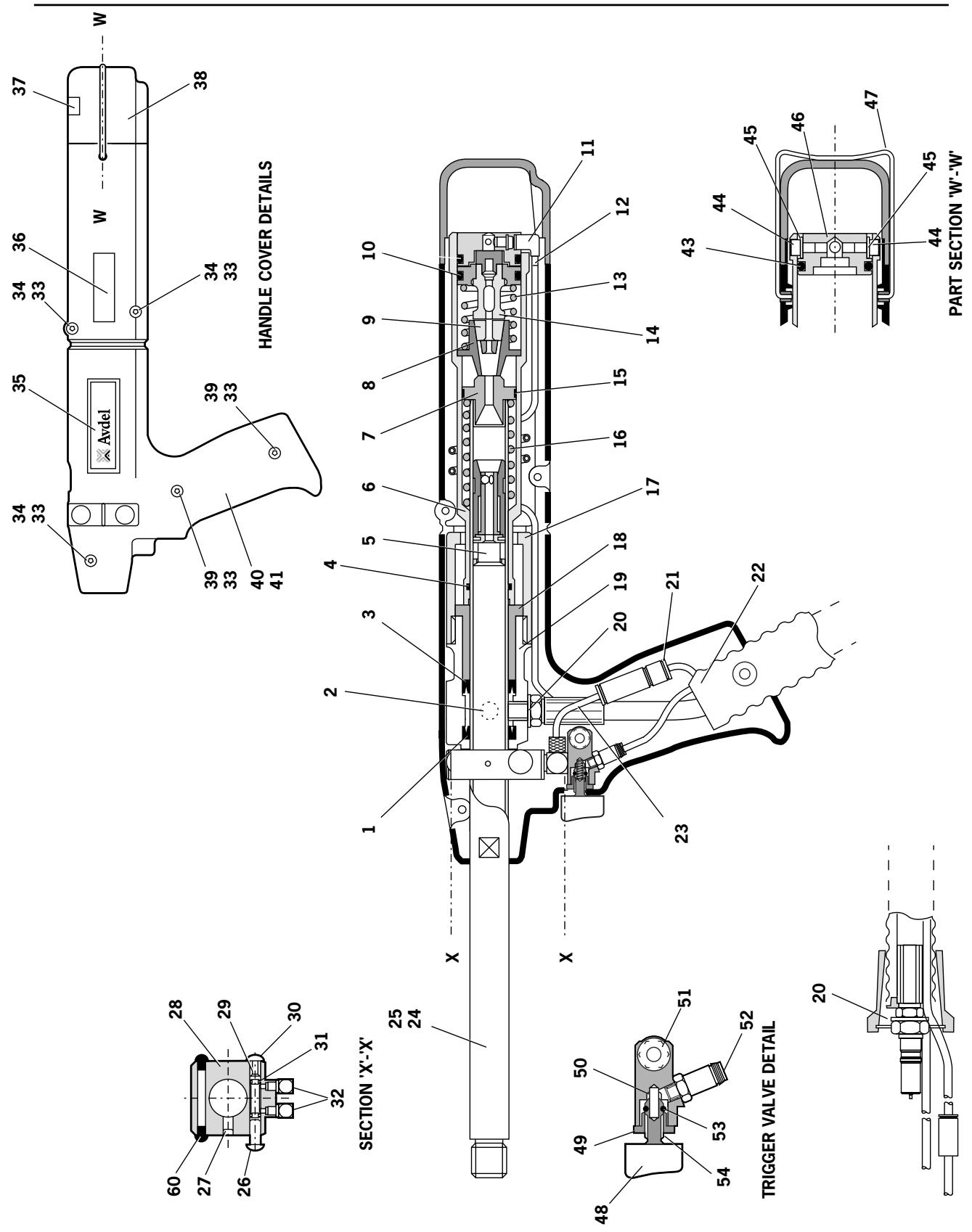
| 07530-02200 PARTS LIST | |||||||||
| ITEM | PART N° | DESCRIPTION | QTY | SPARES | ITEM | PART N° | DESCRIPTION | QTY | SPARES |
| 1 | 07003-00237 | SEAL (STATIC) | 1 | - | 29 | 07530-02302 | AIR TAIL JAW SPOOL | 1 | - |
| 2 | 07530-00500 | BLEED PLUG ASSEMBLY (ITEMS 56 to 59) | 1 | - | 30 | 07004-00059 | 1/8" STARLOCK WASHER BLACK | 1 | - |
| 3 | 07003-00236 | SEAL (DYNAMIC) | 1 | 1 | 31 | 07003-00121 | 'O' RING | 2 | 3 |
| 4 | 07003-00167 | 'O' RING | 1 | 1 | 32 | 07005-01571 | ELBOW CONNECTOR | 2 | - |
| 5 | 07271-01100 | MECHANICAL CURSOR ASSEMBLY | 1 | - | 33 | 07002-00134 | M4 HEX NUT | 5 | - |
| 6 | 07530-02207 | TAIL JAW CYLINDER | 1 | - | 34 | 07001-00401 | M4 X 10 LONG SOCKET HEAD CAP SCREW | 3 | - |
| 7 | 07530-02205 | BARREL PLUG | 1 | - | 35 | 07530-02210 | LABEL | 2 | - |
| 8 | 07530-00208 | JAW HOUSING | 1 | - | 36 | 07007-01504 | CE MARK LABEL | 1 | - |
| 9 | 07151-00403 | JAWS | 2 | 2 | 37 | 07007-01503 | BOOK SYMBOL LABEL | 1 | - |
| 10 | 07003-00113 | 'O' RING | 1 | 2 | 38 | 07530-02603 | END CAP | 1 | - |
| 11 | 07005-01972 | L TYPE THREADED NIPPLE | 1 | - | 39 | 07001-00262 | M4 X 22 LONG SOCKET HEAD CAP SCREW | 2 | - |
| 12 | 07530-02211 | AIR TAIL JAW CONCERTINA TUBE | 1 | - | 40 | 07530-02601 | MODIFIED HANDLE MOULDING (RIGHT) | 1 | - |
| 13 | 07154-00404 | SPRING | 1 | - | 41 | 07530-02602 | MODIFIED HANDLE MOULDING (LEFT) | 1 | - |
| 14 | 07530-02800 | TAIL JAW PISTON ASSEMBLY | 1 | - | 43 | 07003-00113 | 'O' RING | 1 | - |
| 15 | 07530-00206 | RUBBING STRIP | 1 | 1 | 44 | 07001-00504 | M4 X 6 LONG SOCKET HEAD CAP SCREW | 2 | 2 |
| 16 | 07490-03002 | BARREL RETURN SPRING | 1 | - | 45 | 07002-00153 | M4 WASHER PLASTIC | 2 | - |
| 17 | 07530-00204 | STROKE LIMITER | 1 | - | 46 | 07530-02213 | REAR PLUG | 1 | - |
| 18 | 07530-00203 | PISTON | 1 | - | 47 | 07530-02220 | CLIP | 1 | - |
| 19 | 07530-02202 | BODY | 1 | - | 48 | 07007-00300 | TRIGGER BUTTON | 1 | - |
| 20 | 07003-00142 | 1/8" BSP BONDED SEAL | 2 | 2 | 49 | 07220-00803 | RETAINER | 1 | - |
| 21 | 07005-01973 | NON-RETURN VALVE | 1 | - | 50 | 07125-00215 | SPRING | 1 | - |
| 22 | 07008-00423 | HYDRAULIC HOSE ASSEMBLY | 1 | - | 51 | 07530-02311 | TRIGGER HOUSING | 1 | - |
| 23 | 07005-01083 | 4mm O/D BLUE PLASTIC TUBE | 60mm | - | 52 | 07005-01357 | COLLET TYPE CONNECTOR | 1 | - |
| 24 | 07007-00017 | DUST CAP | 1 | - | 53 | 07003-00022 | 'O' RING | 1 | - |
| 25 | 07530-02201 | BARREL | 1 | - | 54 | 07241-00208 | SPINDLE | 1 | - |
| 26 | 07004-00058 | 1/8" STARLOCK WASHER CHROME | 1 | - | 56 | 07003-00142 | ● BONDED SEAL | 1 | 1 |
| 27 | 07001-00404 | M5 X 6 LONG SOCKET HEAD SCREW | 1 | - | 57 | 07003-00194 | ● BONDED SEAL | 1 | 1 |
| 28 | 07530-02301 | SWITCH BLOCK | 1 | - | 58 | 07001-00442 | ● SCREW | 1 | - |
| 59 | 07530-00501 | ● PLUG | 1 | - | |||||
| 60 | 07530-00310 | BLANKING PLUGS | 2 | ||||||
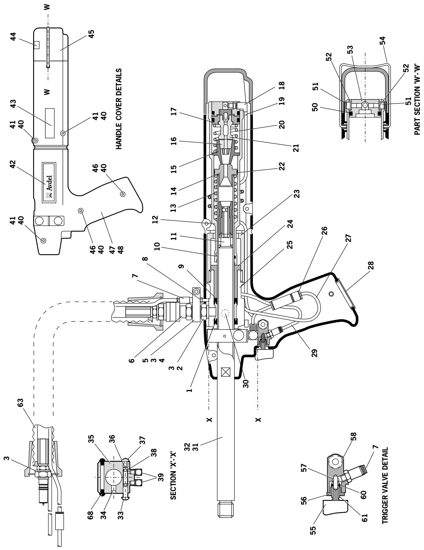
| 07532-02200 PARTS LIST | |||||||||
| ITEM | PART N° | DESCRIPTION | QTY | SPARES | ITEM | PART N° | DESCRIPTION | QTY | SPARES |
| 1 | 07003-00237 | SEAL (STATIC) | 1 | - | 33 | 07004-00058 | 1/8" STARLOCK WASHER CHROME | 1 | - |
| 2 | 07532-00203 | ADAPTOR TOP HOSE | 1 | - | 34 | 07001-00404 | M5 X 6 LONG SOCKET HEAD SCREW | 1 | - |
| 3 | 07003-00142 | 1/8" BSP BONDED SEAL | 4 | 2 | 35 | 07530-02301 | SWITCH BLOCK | 1 | - |
| 4 | 07532-02202 | SUSPENSION MOUNTING PLATE | 1 | - | 36 | 07530-02302 | AIR TAIL JAW SPOOL | 1 | - |
| 5 | 07532-00205 | MODIFIED SCREW | 1 | - | 37 | 07004-00059 | 1/8" STARLOCK WASHER BLACK | 1 | - |
| 6 | 07005-00759 | SELF CLOSING COUPLER | 1 | - | 38 | 07003-00121 | 'O' RING | 2 | 3 |
| 7 | 07005-01357 | COLLET TYPE CONNECTOR | 3 | - | 39 | 07005-01571 | ELBOW CONNECTOR | 2 | - |
| 8 | 07005-01325 | BARBED STRAIGHT CONNECTOR | 2 | - | 40 | 07002-00134 | M4 HEX NUT | 5 | - |
| 9 | 07003-00236 | SEAL (DYNAMIC) | 1 | 1 | 41 | 07001-00401 | M4 X 10 LONG SOCKET HEAD CAP SCREW | 3 | - |
| 10 | 07003-00167 | 'O' RING | 1 | 1 | 42 | 07530-02210 | LABEL | 2 | - |
| 11 | 07271-01100 | MECHANICAL CURSOR ASSEMBLY | 1 | - | 43 | 07007-01504 | CE MARK LABEL | 1 | - |
| 12 | 07530-02207 | TAIL JAW CYLINDER | 1 | - | 44 | 07007-01503 | BOOK SYMBOL LABEL | 1 | - |
| 13 | 07490-03002 | BARREL RETURN SPRING | 1 | - | 45 | 07530-02603 | END CAP | 1 | - |
| 14 | 07530-02205 | BARREL PLUG | 1 | - | 46 | 07001-00262 | M4 X 22 LONG SOCKET HEAD CAP SCREW | 2 | - |
| 15 | 07530-00208 | JAW HOUSING | 1 | - | 47 | 07532-02208 | MODIFIED HANDLE MOULDING (RIGHT) | 1 | - |
| 16 | 07151-00403 | JAWS | 2 | 2 | 48 | 07532-02209 | MODIFIED HANDLE MOULDING (LEFT) | 1 | - |
| 17 | 07003-00113 | 'O' RING | 1 | 2 | 50 | 07003-00113 | 'O' RING | 1 | - |
| 18 | 07005-01972 | L TYPE THREADED NIPPLE | 1 | - | 51 | 07001-00504 | M4 X 6 LONG SOCKET HEAD CAP SCREW | 2 | 2 |
| 19 | 07530-02211 | AIR TAIL JAW CONCERTINA TUBE | 1 | - | 52 | 07002-00153 | M4 WASHER PLASTIC | 2 | - |
| 20 | 07154-00404 | SPRING | 1 | - | 53 | 07530-02213 | REAR PLUG | 1 | - |
| 21 | 07530-02800 | TAIL JAW PISTON ASSEMBLY | 1 | - | 54 | 07530-02220 | CLIP | 1 | - |
| 22 | 07530-00206 | RUBBING STRIP | 1 | 1 | 55 | 07007-00300 | TRIGGER BUTTON | 1 | - |
| 23 | 07530-00204 | STROKE LIMITER | 1 | - | 56 | 07220-00803 | RETainer | 1 | - |
| 24 | 07530-00203 | PISTON | 1 | - | 57 | 07125-00215 | SPRING | 1 | - |
| 25 | 07530-02202 | BODY | 1 | - | 58 | 07530-02311 | TRIGGER HOUSING | 1 | - |
| 26 | 07005-01973 | NON-RETURN VALVE | 1 | - | 60 | 07003-00022 | 'O' RING | 1 | - |
| 27 | 07005-01083 | 4mm O/D BLUE PLASTIC TUBE | 350mm | - | 61 | 07241-00208 | SPINDLE | 1 | - |
| 28 | 07532-02215 | SEALING PLUG | 1 | - | 63 | 07008-00414 | HYDRAULIC HOSE ASSEMBLY | 1 | - |
| 29 | 07005-01084 | 4mm O/D BLACK PLASTIC TUBE | 220mm | - | 64 | 07003-00142 | ● BONDED SEAL | 1 | 1 |
| 30 | 07530-00500 | BLEED PLUG ASSEMBLY (ITEMS 64 to 67) | 1 | - | 65 | 07003-00194 | ● BONDED SEAL | 1 | 1 |
| 31 | 07530-02201 | BARREL | 1 | - | 66 | 07001-00442 | ● SCREW | 1 | - |
| 32 | 07007-00017 | DUST CAP | 1 | - | 67 | 07530-00501 | ● PLUG | 1 | - |
| 68 | 07530-00310 | BLANKING PLATE | 2 | ||||||
Dismantling Instructions
- When dismantling the intensifier assembly, first disconnect the air supply hose to intensifier inlet Connector 22.
Using an Allen Key* undo four Screws 27 and remove Protection Plate 24. - Disconnect the trigger hose (item 22 on page 28 or item 29 on page 30) from the intensifier Valve 43 or 48 by depressing the outlet collet and withdrawing the hose.
- Remove Cover Plate 4 and Gasket 35 by removing Screws 37 and Washers 36 using Allen Key*.
- Ensure that gasket is not damaged to ensure a proper seal on assembly.
- Invert intensifier assembly and drain oil from reservoir into a suitable container.
- Remove Quick Release Connector 32 together with Connector 31 and Seals 33 with suitable spanner*.
- Remove intensifier Valve 43 or 48 by removing the fixing screws with a suitable spanner taking care to retain 'O' Ring 21 located in the Intensifier Body Casting.
- Remove Screw 19 using a suitable Allen Key* and remove Silencer Cover 16, Foam Silencer 15, Spacer 18 and Retaining Plate 20.
Pull off the 6mm Plastic Tube 41 from Vacuum Connectors 42. -
From the base of the intensifier insert a 3mm Allen Key * through the two holes and unscrew the Vacuum Connectors 42. Note:
-
Care must be taken as the vacuum connectors are locked and sealed in place using Loctite 574.
- If difficult to remove, the vacuum connectors can be drilled out using a 3 / 16" or 4.7mm diameter drill.
To reassemble the Vacuum Connectors 42, the following procedure must be followed: -
Soak the vacuum connectors in a suitable primer, i.e. Perma Bond A905
- Place a drop of Loctite 574 in the intensifier threaded hole.
- From the base of the intensifier insert the Allen Key * through the hole. Ensure that the Allen Key * is free from Loctite 574 before inserting into the vacuum connector.
- Rotate the Allen Key while applying Loctite 574 to the base of the vacuum connector.
- Screw the Vacuum connector into the intensifier, ensuring that there is sufficient Loctite 574 at the base of the fitting such the thread is not visible.
Using a screwdriver, carefully remove internal Retaining Ring 14. Clean and inspect groove for sign of damage.
- Using Extractor, insert male threaded end into End Cover 12 and withdraw it along with intensifier Sleeve 28 and 'O' Rings 10 and 13.
- Insert Rod through the connector orifice at the front of the intensifier body and tap out Piston Rod 9 and Piston Assembly.
Using a suitable Allen Key*, unscrew two Screws 25 and remove End Cover 12 from intensifier Sleeve 28.
- Remove Seal Plug 7 with spanner.
- Insert rod through connector orifice at the front of the intensifier body and push out Seal Housing 5 and associated 'O' rings and lip seals.
- Remove Valve Housing Assembly 34 from the main body with a suitable spanner. Clean by blowing through with a low-pressure air jet.
- Remove Piston Rod 9 from intensifier Air Piston 11 by gripping the first 20mm (3/4^) of the rod in a vice fitted with soft jaws, taking care not to damage or mark the working surface.
- Unscrew locking Nut 17 with a suitable spanner.
- Assemble in the reverse order of dismantling, observing the following:
Clean all parts and renew all 'O' rings.
- Lubricate all seals using Moly Lithium grease.
- Valve Housing Assembly 34 must be refitted using a thread sealing adhesive.
- Assemble the Piston Assembly using a new Nut 17.
End Cover 12 must be fitted correctly inside Retaining Ring 14. The tool must not be operated if the end cover has been omitted.
IMPORTANT
Priming is ALWAYS necessary after the tool has been dismantled and prior to operating.
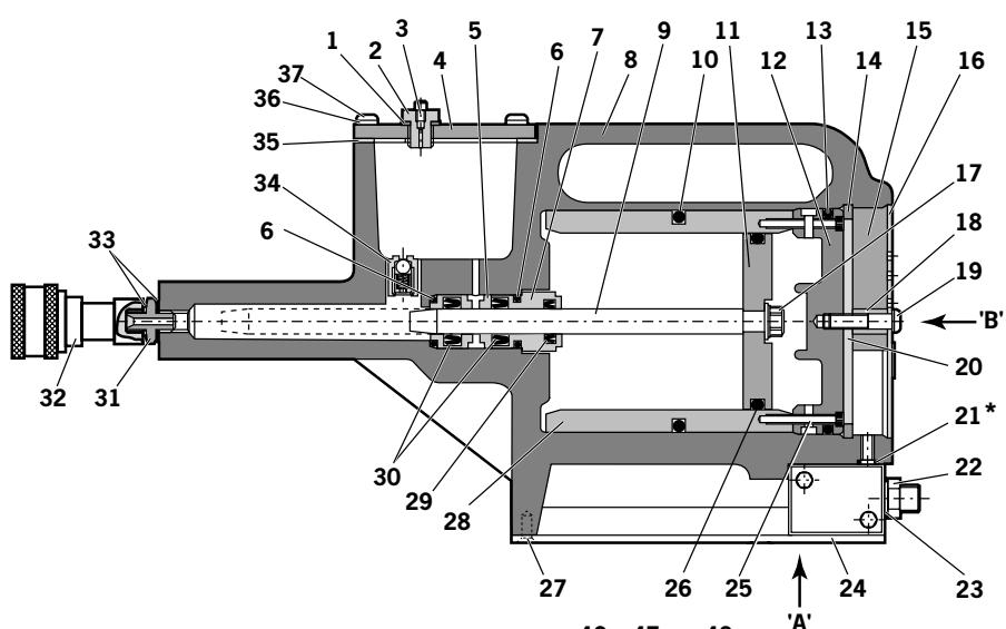
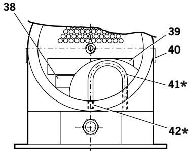
Note
* Some units will not include these items
(The required link is achieved via internal porting)
VIEW ON ARROW 'B'
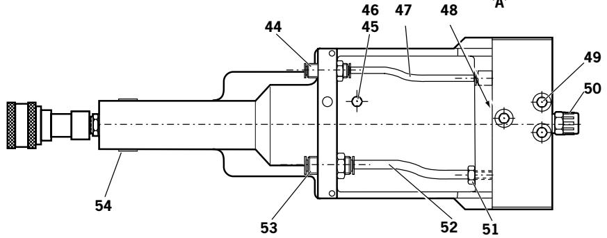
VIEW ON ARROW 'A'
VIEW ILLUSTRATING FESTO VALVE
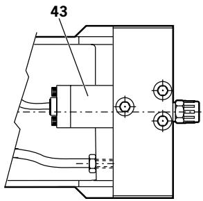
VIEW ILLUSTRATING COMPAIR VALVE
| 07531-02200 PARTS LIST | |||||||||
| ITEM | PART N° | DESCRIPTION | QTY | SPARES | ITEM | PART N° | DESCRIPTION | QTY | SPARES |
| 1 | 07003-00037 | SEAL | 1 | 1 | 28 | 07531-00201 | SLEEVE | 1 | - |
| 2 | 07240-00211 | FILLER SCREW | 1 | - | 29 | 07003-00337 | LIP SEAL | 1 | 1 |
| 3 | 07001-00418 | BLEED SCREW | 1 | 1 | 30 | 07003-00336 | LIP SEAL | 2 | 2 |
| 4 | 07240-00210 | COVER PLATE | 1 | - | 31 | 07005-00406 | CONNECTOR | 1 | - |
| 5 | 71420-02006 | SEAL HOUSING | 1 | - | 32 | 07005-00759 | QUICK RELEASE CONNECTOR | 1 | - |
| 6 | 07003-00153 | 'O' RING | 2 | - | 33 | 07003-00142 | SEAL | 2 | 1 |
| 7 | 71420-02007 | SEAL PLUG | 1 | - | 34 | 07240-00400 | VALVE HOUSING ASSEMBLY | 1 | - |
| 8 | 71420-02300 | BODY ASSEMBLY | 1 | - | 35 | 07240-00209 | GASKET | 1 | 1 |
| 9 | 71420-02008 | PISTON ROD | 1 | - | 36 | 07002-00073 | WASHER | 4 | 1 |
| 10 | 07003-00182 | 'O' RING | 1 | 1 | 37 | 07001-00554 | SCREW | 4 | 1 |
| 11 | 07531-00202 | AIR PISTON | 1 | - | 38 | 07007-01504 | LABEL | 1 | - |
| 12 | 07531-00204 | END COVER | 1 | - | 39 | 07240-00217 | LABEL | 1 | - |
| 13 | 07003-00183 | 'O' RING | 1 | 1 | 40 | 07531-00205 | LABEL | 2 | - |
| 14 | 07004-00069 | RETAINING RING | 1 | 1 | 41 | 07005-00596 | * 6mm PLASTIC TUBE | - | - |
| 15 | 07240-00213 | FOAM SILENCER | 1 | 1 | 42 | 07245-00103 | * VACUUM CONNECTOR | 2 | - |
| 16 | 07240-00214 | SILENCER COVER | 1 | - | 43 | 07005-00590 | COMPAIR VALVE | 1 | 1 |
| 17 | 07002-00017 | NUT | 1 | 1 | 44 | 07005-01431 | BULKHEAD CONNECTOR | 1 | 1 |
| 18 | 07240-00215 | SPACER | 1 | - | 45 | 07005-00668 | M5 PLUG | 1 | - |
| 19 | 07001-00417 | SCREW | 1 | 1 | 46 | 07005-00670 | M5 SEALING RING | 1 | - |
| 20 | 07240-00216 | RETAINING PLATE | 1 | - | 47 | 07005-01084 | 4mm PLASTIC TUBE (150mm) | - | - |
| 21 | * 07003-00042 | 'O' RING | 1 | 1 | 48 | 07005-01524 | FESTO VALVE | 1 | - |
| 22 | 07005-00041 | CONNECTOR | 1 | - | 49 | 07001-00176 | SCREW | 3 | - |
| 23 | 07003-00065 | WASHER | 1 | - | 50 | 07007-00292 | 1/4" BSP REDCAP | 1 | - |
| 24 | 07240-00220 | PROTECTION PLATE | 1 | - | 51 | 07005-00647 | CONNECTOR | 1 | - |
| 25 | 07001-00375 | SCREW | 2 | - | 52 | 07005-01085 | 6mm PLASTIC TUBE (150mm) | - | - |
| 26 | 07003-00238 | 'O' RING | 1 | 1 | 53 | 07005-00855 | BULKHEAD UNION | 1 | - |
| 27 | 07001-00396 | SCREW | 4 | - | 54 | 07007-01503 | LABEL | 1 | - |
Please note that these service instructions refer to the Compair valve where fitted.
Servicing of the valve is limited to the removal/replacement of 'O' rings.
- Remove Screws 24 and remove pilot assembly.
- Remove Piston 11 and discard 'O' Rings 3, 10, 4 and 5.
- Remove Screws 26 and 21 and remove End Caps 22 and 25.
- Withdraw Pistons 12 and 18 and remove 'O' Rings 7 and 9 from pistons.
- Withdraw Spool 16 from bore, taking care not to damage surface of spool and remove location Washers 14 and 17, 'O' Ring 8, Spacers 15 and 'O' Ring 6 from each end of valve body.
- Remove five interface 'O' Rings 4.
Discard ALL 'O' rings removed.
Clean all parts with paraffin or white spirit. DO NOT USE SOLVENTS. Dry all parts. - Lightly smear bores of valve Body 23, pilot valve Body 19, both End Caps 22 and 25 and all replacement 'O' rings with CENTOPLEX 2 grease.
- Fit new 'O' Rings 10, 4 and 5 to Piston 11 and insert into pilot valve body.
- Fit new 'O' Rings 3, 10 and 6 to pilot valve body, place Top Cap 20 in position and secure pilot valve assembly to main valve Body 23 with Screws 24. Ensure that the interface seal housing faces upward with the G1/4 at the bottom. Ensure orientation of Piston 11 is correct.
- With main valve Body 23 in the same position, fit green location Washer 17 to the left hand side of the valve assembly.
- Starting from the right hand side of the valve, assemble alternately 'O' Rings 8 and Spacers 15 (6 seals and 5 spacers) and finally complete the stack assembly with white location Washer 14.
Lightly smear Spool 16 with CENTOLEX 2 grease, supplied with the service kit, and slide spool through seal/spacer stack. - Fit 'O' Rings 9 and 7 to respective Pistons 18 and 12, fit 'O' Rings 6 to ends of main valve Body 23.
- Insert pistons into End Caps 25 and 22 and assemble end caps to valve, taking care to locate piston shafts into holes in the ends of Spool 16.
- Secure end cap assemblies to main valve Body 23 with Screws 26 and 21.
- Fit interface 'O' Rings 4 into their housings in the main valve body.
If the pipe connection to the pilot assembly is damaged, replace Plastic Collet 2 and lift out the 'O' Ring 1 from Cartridge 27. - Fit new 'O' Ring 1 and insert Plastic Collet 2 into Cartridge 27.
IMPORTANT
Priming is ALWAYS necessary after the tool has been dismantled and prior to operating.
Item numbers in bold refer to the illustration and parts list opposite.
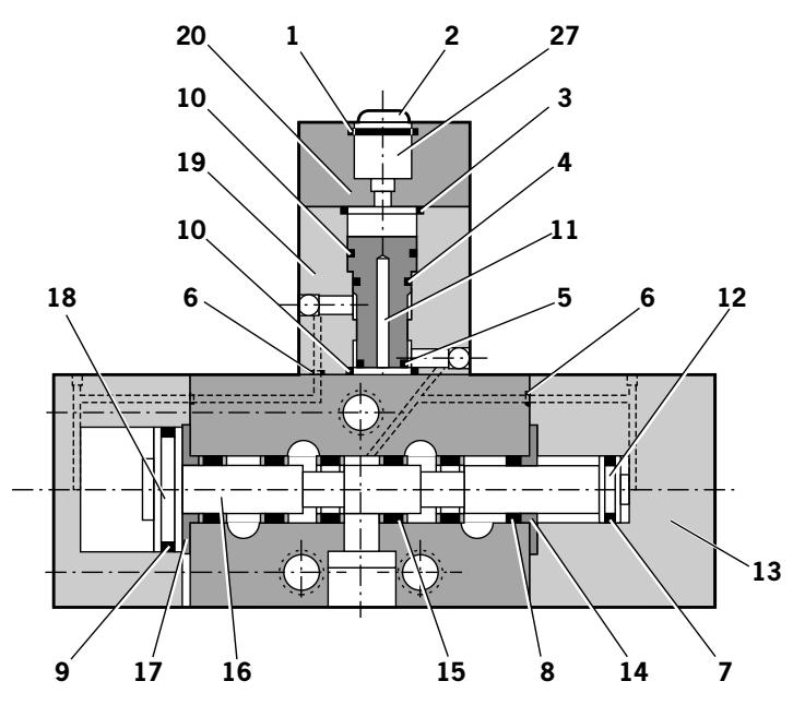
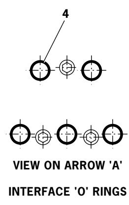
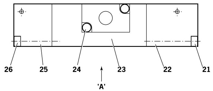
| 07005-00590 VALVE PARTS LIST | |||||||||
| ITEM | PART N° | DESCRIPTION | QTY | SPARES | ITEM | PART N° | DESCRIPTION | QTY | SPARES |
| 1 | 07005-00599 | * 'O' RING | - | - | 15 | - | † SPACER | 5 | - |
| 2 | 07005-00598 | * PLASTIC COLLET | - | - | 16 | - | † SPOOL | 1 | - |
| 3 | 07003-00204 | * 'O' RING | 1 | - | 17 | - | † WASHER | 1 | - |
| 4 | 07003-00103 | * 'O' RING | 6 | - | 18 | - | † PISTON | 1 | - |
| 5 | 07003-00042 | * 'O' RING | 1 | - | 19 | - | † BODY | 1 | - |
| 6 | 07003-00121 | * 'O' RING | 4 | - | 20 | - | † TOP CAP | 1 | - |
| 7 | 08005-00127 | * 'O' RING | 1 | - | 21 | - | † SCREW | 2 | - |
| 8 | 07003-00105 | * 'O' RING | 6 | - | 22 | - | † END CAP | 1 | - |
| 9 | 07003-00178 | * 'O' RING | 1 | - | 23 | - | † BODY | 1 | - |
| 10 | 07003-00017 | * 'O' RING | 2 | - | 24 | - | † SCREW | 2 | - |
| 11 | - | † PISTON | 1 | - | 25 | - | † END CAP | 1 | - |
| 12 | - | † PISTON | 1 | - | 26 | - | † SCREW | 2 | - |
| 13 | 07005-00590 | VALVE ASSEMBLY | - | - | 27 | - | † CARTRIDGE | 1 | - |
| 14 | - | † WASHER | 1 | - | |||||
Together these items make up a Service Kit for the valve with the addition of one Centoplex 2 tube of grease, the kit is available from Avdel, part number 07005-01538.
Not available as a spare
Priming is ALWAYS necessary after the tool has been dismantled and prior to operating. It may also be necessary to restore the full stroke after considerable use, when the stroke may be reduced and fasteners are not fully placed by one operation of the trigger.
Oil Details
The recommended oil for priming is Hyspin VG32 and AWS 32 available in 0.5l (part number 07992-00002) or one gallon containers (part number 07992-00006). Please see safety data below.
Hyspin VG 32 and AWS 32 Oil Safety Data
First Aid
SKIN:
Wash thoroughly with soap and water as soon as possible. Casual contact requires no immediate attention. Short term contact requires no immediate attention.
INGESTION:
Seek medical attention immediately. DO NOT induce vomiting.
EYES:
Irrigate immediately with water for several minutes. Although NOT a primary irritant, minor irritation may occur following contact.
Fire
Suitable extinguishing media: CO_2 , dry powder, foam or water fog. DO NOT use water jets.
Environment
WASTE DISPOSAL: Through authorised contractor to a licensed site. May be incinerated. Used product may be sent for reclamation.
SPILLAGE: Prevent entry into drains, sewers and water courses. Soak up with absorbent material.
Handling
Wear eye protection, impervious gloves (e.g. of PVC) and a plastic apron. Use in well ventilated area.
Storage
No special precautions.
Priming Procedure
IMPORTANT
DO NOT OPERATE THE TRIGGER WHILE THE BLEED SCREW IS REMOVED
All operations should be carried out on a clean bench, with clean hands in a clean area.
Ensure that the new oil is perfectly clean and free from air bubbles.
Care MUST be taken at all times, to ensure that no foreign matter enters the tool, or serious damage may result.
- Remove Screw 2 and Seal 1 from Plastic Cover plate 4 on the intensifier reservoir.
Pour the priming oil into the reservoir until it is approximately 1 / 2'' (12mm) from the top. - Replace Screw 2 and Seal 1.
- Connect the intensifier unit to the air supply. Remove screw from reservoir.
- With the pistol unit fitted to the intensifier unit and held below the level of the intensifier unit, unscrew Bleed Screw 58 from Bleed Plug Assembly 2 on the 07530 Mk II tool or Bleed Screw 66 from Bleed Plug Assembly 30 on the 07532 Mk II tool two turns and allow oil to flow out of the tool.
- When the oil runs freely and free of air bubbles, tighten the bleed screw.
- Top up the reservoir on the intensifier unit with priming oil.
- Cycle the tool until any air bubbles present in the oil are expelled into the oil reservoir.
Item numbers in bold refer to the general assemblies and parts lists pages 28-33.
| Symptom | Possible Cause | Remedy | Page Ref |
| Tool will not place fastener | Low air pressure. | Increase air pressure | |
| Lack of lubrication. | Lubricate tool at air inlet point | ||
| High broach load. | Check fastener grip and application hole size | ||
| Check for correct size mandrel. | |||
| Worn or broken tail jaws. | New tail jaws | ||
| Tail jaws switched off. | Switch on tail jaws | ||
| Air in hydraulic system. | See ‘Priming Procedure’ | 36 | |
| ‘Mandrel Slip’ - jaws will not grip mandrel | Worn or dirty tail jaws. | Clean or renew as necessary | |
| ‘Insufficient air pressure/volume. | Increase air pressure/volume | ||
| ’Tail jaw switch inoperable. | Replace switch | ||
| ’Air leaks to tail jaws. | Renew ‘O’ rings on piston 8 | ||
| Mandrel broken and not reaching tail jaws. | Replace mandrel | ||
| Defective non-return valve. | Replace non-return valve | ||
| Jaws will not release mandrel | Dirty tail jaws or jaw housing. | Clean and lubricate | |
| Faulty tail jaw switch. | Replace ‘O’ rings | ||
| Fasteners will not feed through nose jaws | Tail jaws not switched on. | Switch on tail jaws | |
| Worn tail jaws. | Renew tail jaws | ||
| Cursor orientation incorrect. | Refit, ensuring correct orientation | ||
| Incorrect cursor | Fit correct cursor | ||
| Incorrect nose jaws. | Fit correct nose jaws | ||
| Mandrel follower spring not fitted. | Fit correct mandrel follower spring | ||
| Incorrect gap between fastener head and nose jaws when loaded. | Set gap to 1.5mm - 3mm (1/16” - 1/8”) See ‘Loading the Tool’ | 10 | |
| Cursor sticking. | Clean and oil cursor | ||
| Weak outer spring around cursor. | Renew cursor | ||
| Incorrect mandrel follower spring fitted. | Fit correct mandrel follower spring | ||
| Excessive tail jaw wear | High broach load. | Check application hole size and thickness and fastener grip capability | |
| Feeding more than one fastener at a time | Mandrel slip. | Check as for ‘Mandrel Slip’, stage 2 | |
| Incorrect gap between fastener head and nose jaws when loaded | Set gap to 1.5mm - 3mm (1/16” - 1/8”) See ‘Loading the Tool’ | 10 |
Other symptoms or failures should be reported to your local Avdel authorised distributor or repair centre.
Model 0753 MkII type 07530 - 07532 models
Hand Tool Serial No.
Intensifier Serial No.
to which this declaration relates is in conformity with the following standards:
EN292 part 1 and part 2
ISO 8662 part 1
EN 60742/0695
ISO 3744
EN 50081-1
ISO PREN792 part 14
EN 55014
following the provisions of the Machine Directive 98/37/EC

A. Seewraj - Product Engineering Manager Automation Tools
Date of issue

This box contains a power tool which is in conformity with Machines Directive 98/37/EC. The 'Declaration of Conformity' is contained within.
Nous, Avdel UK Limited; Watchmead Industrial Estate, Welwyn Garden City, Hertfordshire, AL7 1LY
| NIETBEZECHNUNG | NIETGRÖSSE | |||||||||||
| 2,4mm | 3,2mm | 4,0mm | 4,8mm | 6,4mm | 2,5mm2,8mm | 3mm | 3,5mm | 4mm | 6mm | M2.54-40UNC | M36-32UNC | |
| CHOBERT® | ● | ● | ● | ● | ● | |||||||
| GROVIT® | ● | ● | ● | ● | ||||||||
| AVLUG® | ● | ● | ||||||||||
| BRIV® | ● | ● | ● | ● | ● | |||||||
| RIVSCREW® | ● | ● | ● | ● | ||||||||
| AVTRONIC® | ● | |||||||||||
| AVSERT® | ● | ● | ||||||||||
Artikelnummer 07530-02100

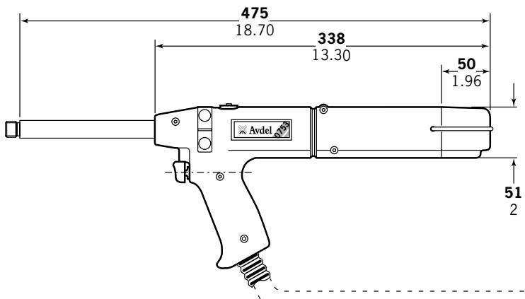
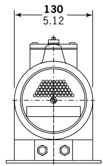
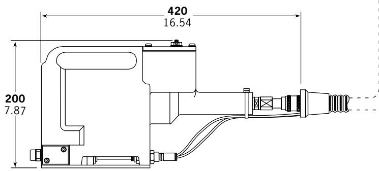
| NOME RIVETTO | DIMENSIONE RIVETTO | |||||||||||
| 2,4mm | 3,2mm | 4,0mm | 4,8mm | 6,4mm | 2,5mm2,8mm | 3mm | 3,5mm | 4mm | 6mm | M2.54-40UNC | M36-32UNC | |
| CHOBERT® | ● | ● | ● | ● | ● | |||||||
| GROVIT® | ● | ● | ● | ● | ||||||||
| AVLUG® | ● | ● | ||||||||||
| BRIV® | ● | ● | ● | ● | ● | |||||||
| RIVSCREW® | ● | ● | ● | ● | ||||||||
| AVTRONIC® | ● | |||||||||||
| AVSERT® | ● | ● | ||||||||||
DIMENSIONE FORO APPLICATION
The recommended oil for priming is Hyspin VG32 and AWS 32 available in 0.5l (part number 07992-00002) or one gallon containers (part number 07992-00006). Please see safety data below.
Noi, Avdel UK Limited; Watchmead Industrial Estate, Welwyn Garden City, Hertfordshire, AL7 1LY,
Rowville, Victoria 3178
Tel: +61 3 9765 6400
Fax: +61 3 9765 6445
Email: info@acument.com.au
CANADA
Avdel Canada, a Division of Acument
Canada Limited
87 disco Road
Rexdale
Ontario M9W 1M3
Tel: +1 416 679 0622
Fax: +1 416 679 0678
Email: infoAvdel-Canada@acument.com
CHINA
Acument China Ltd.
RM 1708, 17/F., Nanyang Plaza,
57 Hung To Rd., Kwun Tong
Hong Kong
Tel: +852 2950 0631
Fax: +852 2950 0022
Email: infochina@acument.com.
FRANCE
Avdel France S.A.S.
3-1 Chigasaki-Chuo, Tsuzuki-ku,
Yokohama-city, Kanagawa Prefecture
Japan 224-0032
Tel: +81 45 947 1200
Fax:+81459471205
Email: info@acument.co.jp
SINGAPORE
Acument Asia Pacific (Pte) Ltd.
05-03/06 Techlink
31 Kaki Bukit Road 3
Singapore, 417818
Tel: +65 6840 7431
Fax: +65 6840 7409
Email: Tlim@acument.com
SOUTH KOREA
Acument Korea Ltd.
212-4, Suyang-Ri,
Silchon-Eup, Kwangju-City,
Kyunggi-Do, Korea, 464-874
Tel: +82 31 798 6340
Fax:+82317986342
Email: info@acumentkorea.com
SPAIN
Avdel Spain S.A.
C/Puerto de la Morcuera,14
Poligono Industrial Prado Overa
Ctra.deToledo,km7,8
28919 Leganés (Madrid)
Tel: +34 (0) 91 3416767
Fax: +34 (0) 91 3416740
Email:ventas@acument.com
UNITED KINGDOM
Avdel UK Limited
Pacific House
2 Swiftfields
Watchmead Industrial Estate
Welwyn Garden City
Hertfordshire
AL71LY
Tel: +44 (0) 1707 292000
Fax: +44 (0) 1707 292199
Email: enquiries@acument.com
USA
Avdel USA LLC
614 NC Highway 200 South
Stanfield,
North Carolina 28163
Email: infoAvdel-USA@acument.com
| Manual No. | Issue | Change Note No. |
| 07900-00724 | AA | 04/088 |
| B | 07/044 | |
| B2 | 07/103 | |