
SUPERLINE - Phono Preamplifier NAIM - Free user manual and instructions
Find the device manual for free SUPERLINE NAIM in PDF.
| Product type | Phono preamplifier for moving coil cartridges |
| Brand | NAIM |
| Model | SUPERLINE |
| Weight | 7.7 kg |
| Power supply | External via Supercap, Hi-Cap, Flatcap or Naim amplifier with adjusted output |
| Gain (standard) | 64 dB @ 1 kHz |
| Gain (low gain) | 58 dB @ 1 kHz |
| Signal-to-noise ratio | 82 dB (standard), 78 dB (low gain) @ 500 µV input, 0 ohm, A-weighted |
| Frequency response | 10 Hz to >200 kHz (-3 dB) |
| RIAA accuracy | ±0.1 dB (20 Hz to 20 kHz) |
| Crosstalk | >80 dB (20 Hz to 20 kHz) |
| Max output voltage | 7.5 V rms (21 V peak) |
| Input overload level | 5 mV rms (standard), 10 mV rms (low gain) @ 1 kHz |
| Cartridge compatibility | 100 µV to 500 µV (standard), 200 µV to 1 mV (low gain) |
| Input loads (resistance) | 1 kΩ, 500 Ω, 220 Ω, 100 Ω (adjustable via loading plugs) |
| Signal input | BNC or phono (one at a time) |
| Signal output | Via SNAIC power cable or Burndy |
| Main features | Moving coil phono amplification, loading adjustment via plugs, mechanical suspension, dust protection |
| Maintenance and cleaning | Clean connectors by plugging/unplugging while powered off; do not use chemical products |
| Safety | Power off amplifiers before connecting/disconnecting cables; unplug during thunderstorms |
| Spare parts and repairability | Repairs and upgrades only by an authorized Naim dealer or at the factory |
| General information | Requires several weeks of burn-in for optimal performance |
Frequently Asked Questions - SUPERLINE NAIM
User questions about SUPERLINE NAIM
0 question about this device. Answer the ones you know or ask your own.
Ask a new question about this device
Download the instructions for your Phono Preamplifier in PDF format for free! Find your manual SUPERLINE - NAIM and take your electronic device back in hand. On this page are published all the documents necessary for the use of your device. SUPERLINE by NAIM.
USER MANUAL SUPERLINE NAIM
Naim Audio products are conceived with performance as the top priority. Careful installation will help ensure that their full potential is achieved. This manual covers the SuperLine phono amplifier. It begins with some general installation notes. Product specific information begins in Section 3.
1 Connections
It is important for both safety and performance that any standard cables supplied with Naim Audio products are not modified.
1.1 Interconnect Cables
Interconnect plugs and sockets should be kept clean and free from corrosion. The easiest way to clean them is to switch off the equipment, pull the plugs out of their sockets, and push them back in again. Contact cleaners and "enhancers" should not be used as the film they deposit may degrade the sound.
2 General Installation
Naim equipment is designed to offer the finest performance possible avoiding compromise wherever practical. This can lead to circumstances that may be unfamiliar. The notes that follow contain advice specifically related to Naim equipment as well as more general warnings about the use of domestic audio products. Please read them carefully.
2.1 Siting The Equipment
In order to reduce the risk of hum audible from the loudspeakers, power supplies and power amplifiers should be located a reasonable distance away from other equipment. The maximum separation distance for connected equipment is that allowed by the standard interconnect lead.
2.2 Switching On
Source components and power supplies should be switched on before power amplifiers. Always switch amplifiers off and wait a minute before connecting or disconnecting any leads. Always use the power switch on the product rather than a mains outlet switch.
2.3 Running In
Naim equipment takes a considerable time to run in before it performs at its best. The duration varies, but under some conditions the sound may continue to improve for over a month. Better and more consistent performance will be achieved if the system is left switched on for long periods. It is worth remembering however that equipment left connected to the mains can be damaged by lightning.
2.4 Radio Interference
In some circumstances, depending on where you live and the earthing arrangements in your home, you may experience radio frequency interference. Controls on broadcasting in some territories allow very high levels of radio frequency radiation and both the choice and exact siting of equipment may be critical. Susceptibility to radio frequency interference is related to the wide internal bandwidth necessary for high sound quality. A radio frequency filter kit is available for some Naim equipment but sound quality will be progressively compromised as more elements of the kit are fitted. In situations of extreme radio interference Naim equipment may be unsuitable.
2.5 Lightning Precautions
Your Naim hi-fi system can be damaged by lightning and should be turned off and disconnected from the mains when there is risk of lightning strike.
2.6 Problems?
Consumer protection varies from country to country. In most territories a retailer must be prepared to take back any equipment he has sold if it cannot be made to work satisfactorily. A problem may be due to a fault in the system or its installation so it is essential to make full use of your dealer's diagnostic skills. Please contact your local distributor, or Naim Audio directly, if any difficulties cannot be resolved.
Some Naim equipment is made in special versions for different territories and this makes it impracticable to arrange international guarantees. Please establish the local guarantee arrangements with your retailer. Contact Naim Audio directly for help and advice if necessary.
2.7 Service and Updates
It is essential that repairs and updates are only carried out by an authorised Naim retailer or at the factory by Naim itself. Many components are custom made, tested or matched and appropriate replacements are often unobtainable from other sources.
Direct contact to Naim for service or update information should be made initially through Customer Services:
Tel: +44 (0)1722 426600
Email: info@naimaudio.com
Please quote the product serial number (found on its rear panel) in all correspondence.
SuperLine Installation
3 SuperLine Installation
The SuperLine moving coil phono amplifier is designed to extract the best possible musical performance from vinyl disc replay. It should be mounted horizontally on an equipment stand intended for the purpose. It is important to ensure that it is level.
The SuperLine contains no internal power supply and must be connected either to a Naim amplifier incorporating an appropriate power supply output, or to a dedicated Naim power supply. SuperLine output is muted for 2 minutes following switch-on to allow its circuitry to reach optimal status.
Cartridge loading resistance and capacitance can be adjusted by inserting combinations of resistive and capacitive "load plugs" into sockets on the SuperLine rear panel.
The SuperLine incorporates a suspension system to isolate its sensitive components from vibrational energy. The suspension system is protected during shipping by two transit screws. The transit screws must be removed before use. Once the transit screws are removed the SuperLine must not be inverted. Transit screw removal is best carried out once the SuperLine is installed in its final location and all connections are made.
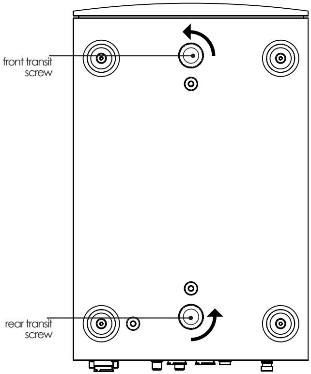
3.1 Transit Screws
Two transit screws must be removed from the underside of the SuperLine before use and replaced if it is to be carried any distance, packed or shipped. Transit screw removal is illustrated in Diagram 3.2. SuperLine transit screws must not be used with any other Naim product.
Damage may result if the SuperLine is inverted either during or after transit screw removal.
To gain access to the transit screws, position one end of the SuperLine over the edge of a table, remove (or replace) the screw that becomes accessible and then repeat with the other end.
3.2 Transit Screw Removal
3.3 Connecting SuperLine
3.3.1 Power Supply
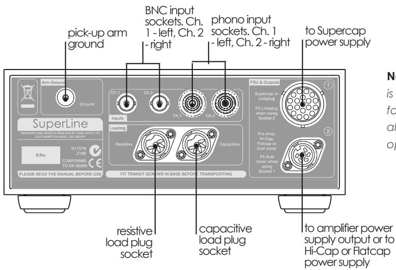
The SuperLine must be connected to a dedicated Supercap, Hi-Cap or Flatcap power supply (option one) or a Naim preamplifier or integrated amplifier that incorporates an appropriate power supply output (option two).
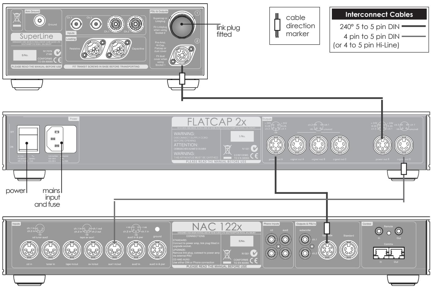
If option one is chosen, connect the SuperLine to the dedicated power supply using, in the case of a Hi-Cap or Flatcap, a Naim SNAIC interconnect cable, and in the case of a Supercap, the appropriate Naim Burndy cable. In either case take care to connect with the correct cable orientation.
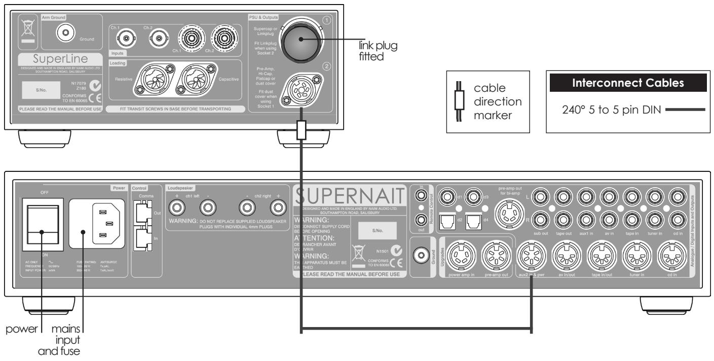
If option two is chosen, connect the SuperLine to the preamplifier or integrated amplifier's 5 pin DIN aux input/ power output socket using a Naim SNAIC interconnect cable. Take care to connect with the correct cable orientation.
Note: If the SuperLine's Burndy power supply socket is not used the supplied Burndy link plug must be inserted. Similarly, if the SuperLine's DIN power supply socket is not used the supplied dust cover should be fitted.
3.3.2 Signal Input
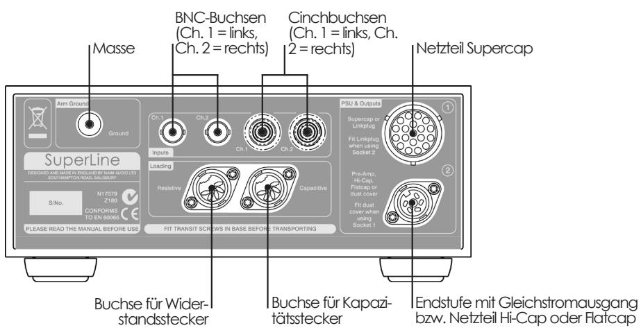
Connect the output cable of the pick-up arm to either the BNC or phono input sockets. Only one option, phono or BNC, should be connected at any time. Take care to ensure that the left and right channels are connected to the appropriate sockets.
Connect the pick-up arm earth lead to the rear panel ground terminal.
3.3.3 Signal Output
The SuperLine output signal is carried on the power supply cable either directly to the preamplifier or via an optional power supply.
SuperLine Installation
3.4 Cartridge Loading
The resistive and capacitive input load presented by the SuperLine to the pick-up cartridge can be adjusted by inserting a combination of "load plugs" into the appropriate sockets in the rear panel.
The appropriate load plug combination will depend on both the manufacturer's recommendations for the pick-up cartridge in use and subjective preference.
Each load plug is constructed from a 5-pin DIN plug that contains the appropriate passive components. A label on each load plug identifies its load value.
Seven standard load plugs are supplied - four resistiveand three capacitive - to provide 20 combinations
(including the default input loads applied when no load plugs are inserted). Table 3.5 lists the standard load plug combinations.
Note: In addition to the standard load plugs supplied, 470 and 560 resistive plugs are also available on request. Other values may also be created either by modifying standard plugs or manufacturing new ones. Contact your retailer or local distributor for more information.
Always ensure that resistive and capacitive load plugs are inserted in the correct socket.
Note: The SuperLine incorporates 10k resistance and 100pF (0.1nF) capacitance loads internally. With no load plugs fitted these values constitute the default load.
3.5 Cartridge Load Plug Combinations
| Resistance | Capacitance | Comments |
| 10kΩ | 100pF | Internal load only. No plugs fitted. |
| 10kΩ | 1nF | No resistive plug fitted. |
| 10kΩ | 5.6nF | No resistive plug fitted. |
| 10kΩ | 10nF | No resistive plug fitted. |
| 1kΩ | 100pF | No capacitive plug fitted. |
| 1kΩ | 1nF | |
| 1kΩ | 5.6nF | |
| 1kΩ | 10nF | |
| 500Ω | 100pF | No capacitive plug fitted. |
| 500Ω | 1nF | Note 1 |
Note 1: Approximates to a Naim 'K' load (560Ω and 1nF).
| Resistance | Capacitance | Comments |
| 500Ω | 5.6nF | Note 2. |
| 500Ω | 10nF | |
| 220Ω | 100pF | No capacitive plug fitted. |
| 220Ω | 1nF | |
| 220Ω | 5.6nF | |
| 220Ω | 10nF | |
| 100Ω | 100pF | No capacitive plug fitted. |
| 100Ω | 1nF | |
| 100Ω | 5.6nF | |
| 100Ω | 10nF |
Note 2: Approximates to a Naim 'S' load (470Ω and 6.8nF).
4 SuperLine Connections
4.1 SuperLine Rear
Note: SuperLine output is muted for 2 minutes following switch-on to allow its circuitry to reach optimal status.
SuperLine Connections
4.2 SuperLine connected to Supernait
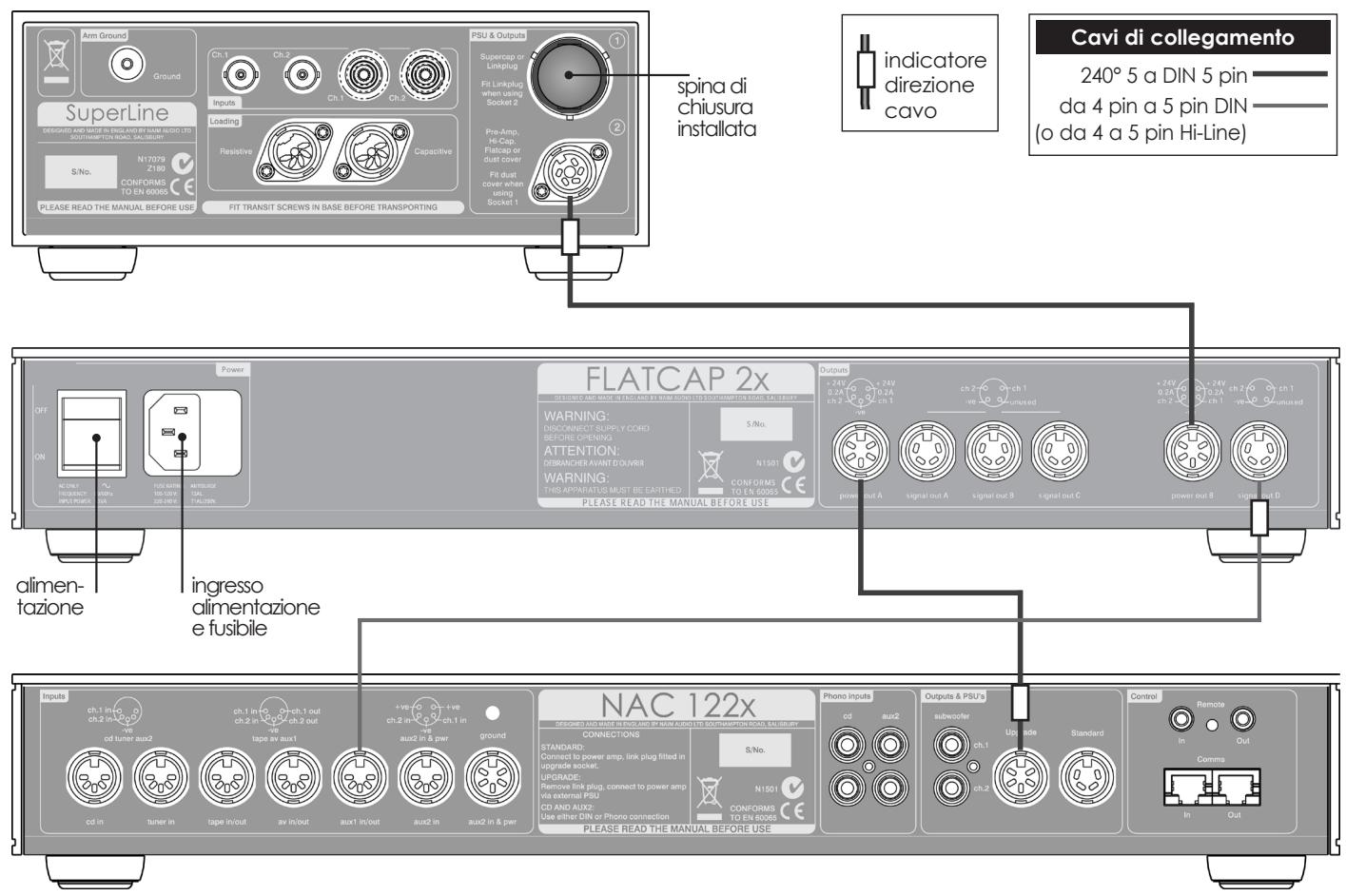
4.3 SuperLine connected to NAC 122x and Flatcap 2x
SuperLine Connections
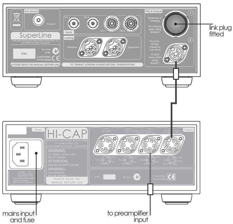
4.4 SuperLine connected to Hi-Cap

cable direction marker
Interconnect Cables
240^5 to 5 pin DIN
4 pin to 5 pin DIN (or 4 to 5 pin Hi-Line)
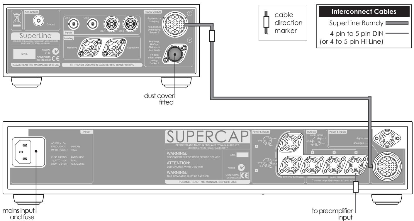
4.5 SuperLine connected to Supercap
SuperLine Specifications
5 SuperLine Specification
5.1 Standard Model
Cartridge compatibility 100 V to 500 V
Gain 64dB @ 1kHz
Signal to Noise 82dB ref 500 V input, 0 Ohms (A-weighted)
Distortion <0.005% (500μV @1kHz)
Frequency response 10Hz to >200kHz -3dB
RIAA accuracy +10Hz HPF +/-0.1dB (20Hz to 20kHz)
Crosstalk >80dB (20Hz to 20kHz)
Max output 7.5VRMS (21Vpkpk)
Input overload 5mVrms (1kHz)
Weight 7.7kg
Input load options 1kΩ, 500Ω, 220Ω, 100Ω (resistive)
1nF, 5.6nF, 10nF (capacitive)
Dimensions 87 x 207 x 314mm
5.2 Low Gain Model (E version)
Cartridge compatibility 200 V to 1mV
Gain 58dB @ 1kHz
Signal to Noise 78dB ref 500 V input, 0 Ohms (A-weighted)
Distortion <0.005% (500μV @1kHz)
Frequency response 10Hz to >200kHz -3dB
RIAA accuracy + 10Hz HPF +/-0.1dB (20Hz to 20kHz)
Crosstalk >80dB (20Hz to 20kHz)
Max output 7.5VRMS (21Vpkpk)
Input overload 10mVrms (1kHz)
Weight 7.7kg
Input load options 1kΩ, 500Ω, 220Ω, 100Ω (resistive)
1nF, 5.6nF, 10nF (capacitive)
Dimensions 87× 207× 314mm

Einleitung
4 SuperLine - Anschlüsse
4.1 Rückseite
SuperLine - Anschlüsse
SuperLine - Anschlüsse
1 nF, 5.6 nF, 10 nF (Kapazität)
Abmessungen 87× 207× 314mm (H× B× T)
1 nF, 5.6 nF, 10 nF (Kapazität)
Abmessungen 87× 207× 314mm (H× B× T)

Introduction
Distortion: <0.005% (500μV @1kHz)
1nF, 5.6nF, 10nF (capacité)
Dimensions (HxLxP): 87 × 207 × 314mm
Distortion: <0.005% (500μV @1kHz)
1nF, 5.6nF, 10nF (capacité)
Dimensions (HxLxP): 87 × 207 × 314mm
Introduzione
4.3 SuperLine collegaço a NAC 122x e Flatcap 2x
Distorsione <0.005% (500μV @1kHz)
1nF, 5.6nF, 10nF (capacitivi)
Dimensioni 87× 207× 314mm
Guadagno 58dB @ 1kHz
Distorsione <0.005% (500μV @1kHz)
1nF, 5.6nF, 10nF (capacitivi)
Dimensioni 87× 207× 314mm
- Connections
- Interconnect Cables
- General Installation
- Siting The Equipment
- Switching On
- Running In
- Radio Interference
- Lightning Precautions
- Problems?
- Service and Updates
- SuperLine Installation
- SuperLine Installation
- Transit Screws
- Damage may result if the SuperLine is inverted either during or after transit screw removal.
- Transit Screw Removal
- Connecting SuperLine
- Power Supply
- Signal Input
- Signal Output
- Cartridge Loading
- Cartridge Load Plug Combinations
- SuperLine Connections
- SuperLine Rear
- SuperLine Connections
- SuperLine connected to Supernait
- SuperLine connected to NAC 122x and Flatcap 2x
- Interconnect Cables
- SuperLine Specifications
- SuperLine Specification
- Standard Model
- Low Gain Model (E version)
- Einleitung
- SuperLine - Anschlüsse
- Rückseite
- SuperLine - Anschlüsse
- Introduction
- Introduzione
- SuperLine collegaço a NAC 122x e Flatcap 2x
Brand : NAIM
Model : SUPERLINE
Category : Phono Preamplifier