
RF30 - Network router COMET LABS - Free user manual and instructions
Find the device manual for free RF30 COMET LABS in PDF.
| Product Type | Network Router |
| Brand | COMET LABS |
| Model | RF30 |
| Dimensions (L x W x H) | 200 x 130 x 35 mm |
| Weight | 0.5 kg |
| Power Supply | 12 V DC, 1 A power adapter |
| Power Consumption | 12 W max |
| LAN Interfaces | 4 x 10/100/1000 Mbps Ethernet ports |
| WAN Interface | 1 x 10/100/1000 Mbps Ethernet port |
| Wi-Fi | Not specified, probably integrated |
| Main Functions | Routing, firewall, VPN (IPSec, PPTP), QoS, DHCP server, DMZ, port forwarding, dynamic DNS, URL/MAC filtering |
| Management | Web interface (HTTP/HTTPS), remote access |
| Firmware Update | Via web interface, .bin file |
| Backup / Restore | Exportable and importable configuration |
| Maintenance and Cleaning | Clean with a soft, dry cloth. Do not use liquid or abrasive products. |
| Security | Integrated firewall, packet filtering, WAN request blocking, intrusion detection |
| Spare Parts and Repairability | Not user-repairable. Contact COMET LABS after-sales service. |
| General Information | Professional network router suitable for SMBs. Manual available in PDF on notice-facile.com. |
Frequently Asked Questions - RF30 COMET LABS
User questions about RF30 COMET LABS
0 question about this device. Answer the ones you know or ask your own.
Ask a new question about this device
Download the instructions for your Network router in PDF format for free! Find your manual RF30 - COMET LABS and take your electronic device back in hand. On this page are published all the documents necessary for the use of your device. RF30 by COMET LABS.
USER MANUAL RF30 COMET LABS
(Updated December 14, 2005)
Copyright Information
© 2005 Cometlabs Electric Corporation, Ltd.
The contents of this publication may not be reproduced in whole or in part, transcribed, stored, translated, or transmitted in any form or any means, without the prior written consent of Cometlabs Electric Corporation.
Published by Cometlabs Electric Corporation. All rights reserved.
Disclaimer
Cometlabs does not assume any liability arising out of the application of use of any products or software described herein. Neither does it convey any license under its patent rights nor the patent rights of others. Cometlabs reserves the right to make changes in any products described herein without notice. This publication is subject to change without notice.
Trademarks
Mac OS is a registered trademark of Apple Computer, Inc.
Windows 98, Windows NT, Windows 2000, Windows Me and Windows XP are registered trademarks of Microsoft Corporation.

Your RF30 is built for reliability and long service life. For your safety, be sure to read and follow the following safety warnings.
Read this installation guide thoroughly before attempting to set up your RF30.
Your RF30 is a complex electronic device. DO NOT open or attempt to repair it yourself. Opening or removing the covers can expose you to high voltage and other risks. In the case of malfunction, turn off the power immediately and have it repaired at a qualified service center. Contact your vendor for details.
Connect the power cord to the correct supply voltage.
Carefully place connecting cables to avoid people from stepping or tripping on them.
DO NOT allow anything to rest on the power cord and DO NOT place the power cord in an area where it can be stepped on.
DO NOT use the RF30 in environments with high humidity or high temperatures.
DO NOT use the same power source for the RF30 as other equipment.
DO NOT use your RF30 and any accessories outdoors.
If you wall mount your RF30, make sure that no electrical, water or gas pipes will be damaged during installation.
DO NOT install or use your RF30 during a thunderstorm.
DO NOT expose your RF30 to dampness, dust, or corrosive liquids.
DO NOT use your RF30 near water.
Be sure to connect the cables to the correct ports.
DO NOT obstruct the ventilation slots on your RF30 or expose it to direct sunlight or other heat sources. Excessive temperatures may damage your device.
DO NOT store anything on top of your RF30.
Only connect suitable accessories to your RF30.
Keep packaging out of the reach of children.
If disposing of the device, please follow your local regulations for the safe disposal of electronic products to protect the environment.
TABLE OF CONTENT
CHAPTER 1: INTRODUCTION. 10
1.1 OVERVIEW 10
1.2 PRODUCT HIGHLIGHTS 10
1.2.1 INCREASED BANDWIDTH, SCALABILITY AND RESILIENCE 10
1.2.2 VIRTUAL PRIVATE NETWORK SUPPORT 10
1.2.3 ADVANCED FIREWALL SECURITY 11
1.2.4 INTELLIGENT BANDWIDTH MANAGEMENT 11
1.3 PACKAGE CONTENTS 12
1.3.1 FRONT PANEL 12
1.3.2 REAR PANEL 12
1.3.3 RACK MOUNTING 13
1.3.4 CABLING 14
CHAPTER 2: ROUTER APPLICATIONS 15
2.1 OVERVIEW 15
2.2 BANDWIDTH MANAGEMENT WITH QOS 15
2.2.1 QoS TECHNOLOGY 15
2.2.2 QoS POLICIES FOR DIFFERENT APPLICATIONS 16
2.2.3 GUARANTEED/MAXIMUM BANDWIDTH 18
2.2.4 POLICY BASED TRAFFIC SHAPING 19
2.2.5 PRIORITY BANDWIDTH UTILIZATION 20
2.2.6 MANAGEMENT BY IP OR MAC ADDRESS 20
2.2.7 DIFFSERV (DSCP MARKING) 21
5.4 ISP CONNECTION 147
5.5 PROBLEMS WITH DATE AND TIME 149
D.1 NETWORK BASICS 154
D.1.1 IP ADDRESSES 154
D.1.1.1 Net mask 154
D.1.1.2 Subnet Addressing 155
D.1.1.3 PRIVATE IP ADDRESSES 155
D.1.2 NETWORK ADDRESS TRANSLATION (NAT) 157
D.1.3 DYNAMIC HOST CONFIGURATION PROTOCOL (DHCP) 157
D.2 ROUTER BASICS 158
D.2.1 WHAT IS A ROUTER? 158
D.2.2 WHY USE A ROUTER? 158
D.2.3 ROUTING INFORMATION PROTOCOL (RIP) 158
D.3 FIREWALL BASICS 159
D.3.1 WHAT IS A FIREWALL? 159
D.3.1.1 Stateful Packet Inspection 159
D.3.1.2 Denial of Service (DoS) Attack 159
D.3.2 WHY USE A FIREWALL? 160
APPENDIX E: VIRTUAL PRIVATE NETWORKING 161
E.1 WHAT IS A VPN? 161
E.1.1VPN APPLICATIONS 161
E.2 WHAT IS IPSEC? 162
E.2.1 IPSEC SECURITY COMPONENTS 162
E.2.1.1 Authentication Header (AH) 162
E.2.1.2 Encapsulating Security Payload (ESP) 163
E.2.1.3 Security Associations (SA) 164
E.2.2 IPSEC MODES 165
E.2.3 TUNNEL MODE AH 166
E.2.4 TUNNEL MODE ESP 166
E.2.5 INTERNET KEY EXCHANGE (IKE) 167
F.1 IPSEC LOG EVENT CATEGORIES 169
F.2 IPSEC LOG EVENT TABLE 169
APPENDIX G: BANDWIDTH MANAGEMENT WITH QOS. 171
G.1 OVERVIEW 171
G.2 WHAT IS QUALITY OF SERVICE? 171
G.3 How Does Qos Work? 172
G4 Who Needs QoS? 172
G.4.1 HOME USERS 172
G.4.2 OFFICE USERS 173
APPENDIX H: ROUTER SETUP EXAMPLES 174
H.1 OUTBOUND FAIL OVER 174
H.2 OUTBOUND LOADBALANCING 176
H.3 INBOUND FAIL OVER 179
H.4 DNS INBOUND FAIL OVER 181
H.5 DNS INBOUND LOAD BALANCING 184
H.6 DYNAMIC DNS INBOUND LOAD BALANCING 187
H.7 VPN CONFIGURATION 192
H.7.1 LAN TO LAN 192
H.7.2 HOST TO LAN 194
H.8 IP SEC FAIL OVER (GATEWAY TO GATEWAY) 196
H.9VPN CONCENTRATOR 199
H.10 PROTOCOL BINDING 202
Chapter 1: Introduction
1.1 Overview
Congratulations on purchasing the RF30 Router from Cometlabs. Combining a router with an Ethernet network switch, the RF30 is a state-of-the-art device that provides everything you need to get your network connected to the Internet over your Cable or DSL connection quickly and easily. The Quick Start Wizard and DHCP Server will get first-time users up and running with minimal fuss and configuration, while sophisticated Quality of Service (QoS) and Load Balancing features grant advanced users total control over their network and Internet connection.
This manual illustrates the many features and functions of the RF30, and even takes you through the various ways you can apply this versatile device to your home or office. Take the time now to familiarize yourself with the RF30.
1.2 Product Highlights
1.2.1 Increased Bandwidth, Scalability and Resilience
With integrated Dual WAN ports, the RF30 combines two broadband lines such as DSL or Cable into one Internet connection, providing optimal bandwidth sharing for multiple PCs on your network, or allowing maximum reliability with network redundancy. Load Balancing enables the RF30 to efficiently balance network traffic across two connections, ideal for small-to-medium businesses that require increased bandwidth, network scalability, and resilience for mission-critical network and Internet applications. Auto failover can also be configured to ensure smooth, continuous service should one connection fail, providing maximum business uptime and productivity, plus uninterrupted service for you and your customers.
1.2.2 Virtual Private Network Support
The RF30 supports comprehensive IPSec VPN protocols for businesses to establish private encrypted tunnels over the Internet to ensure data transmission security among multiple sites, such as a branch office or dial-up connection. Up to 30 simultaneous IPSec VPN connections are possible on the RF30, with performance of up to 30Mbps.
1.2.3 Advanced Firewall Security
Aside from intelligent broadband sharing, the RF30 offers integrated firewall protection with advanced features to secure your network from outside attacks. Stateful Packet Inspection (SPI) determines if a data packet is permitted to enter the private LAN. Denial of Service (DoS) prevents hackers from interrupting network services via malicious attacks. In addition, the RF30 firewall can be configured to alert you via email should your network come under fire, offering both tight network security and peace of mind.
1.2.4 Intelligent Bandwidth Management
The RF30 utilizes Quality of Service (QoS) to give you full control over the priority of both incoming and outgoing data, ensuring that critical data such as customer information moves through your network, even while under a heavy load. Transmission speeds can be throttled to make sure users are not saturating bandwidth required for mission-critical data transfers. Priority types of upload data can also be changed, allowing the RF30 to automatically sort out actual speeds for unmatched convenience.
1.3 Package Contents
RF30 iBusiness Security Gateway SMB
Bracket x 2 (for rack-mounting)
Screw x 4 (for rack-mounting)
Getting Started CD-ROM
Quick Start Guide
AC-DC Power Adapter (12VDC, 1A)
1.3.1 Front Panel

| LED | Function |
| Power | A solid light indicates a steady connection to a power source. |
| Status | A blinking light indicates the device is writing to flash memory. |
| LAN 1-8 | Lit when connected to an Ethernet device. 10/100M: Lit green when connected at 100Mbps. Not lit when connected at 10Mbps. Link/ACT: Lit when device is connected. Blinking when data is transmitting/receiving. |
| WAN1 | Lit when connected to an Ethernet device. 10/100M: Lit green when connected at 100Mbps. Not lit when connected at 10Mbps. Link/ACT: Lit when device is connected. Blinking when data is transmitting/receiving. |
| WAN2 | Lit when connected to an Ethernet device. 10/100M: Lit green when connected at 100Mbps. Not lit when connected at 10Mbps. Link/ACT: Lit when device is connected. Blinking when data is transmitting/receiving. |
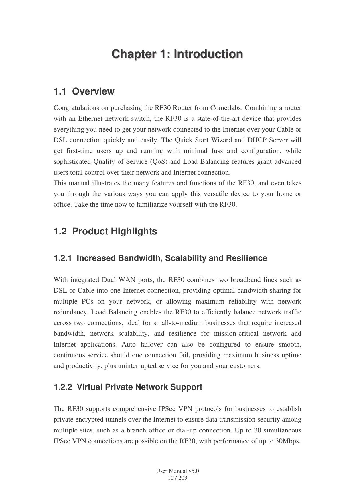
1.3.2 Rear Panel
| Port | Function | |
| 1 | RESET | To reset the device and restore factory default settings, after the device is fully booted, press and hold RESET until the Status LED begins to blink. |
| 2 | WAN2 | WAN2 10/100M Ethernet port (with auto crossover support); connect xDSL/Cable modem here. |
| 3 | WAN1 | WAN1 10/100M Ethernet port (with auto crossover support); connect xDSL/Cable modem here. |
| 4 | LAN 1 — 8 | Connect a UTP Ethernet cable (Cat-5 or Cat-5e) to one of the eight LAN ports when connecting a PC to the network. |
| 5 | DC12V | Connect DC Power Adapter here. (12VDC) |
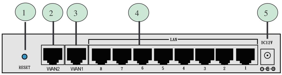
1.3.3 Rack Mounting
To rack mount the RF30, carefully secure the device to your rack on both sides using the included brackets and screws. See the diagram below for a more detailed explanation.
1.3.4 Cabling
Most Ethernet networks currently use unshielded twisted pair (UTP) cabling. The UTP cable contains eight conductors, arranged in four twisted pairs, and terminated with an RJ45 type connector.
One of the most common causes of networking problems is bad cabling. Make sure that all connected devices are turned on. On the front panel of the RF30, verify that the LAN link and WAN line LEDs are lit. If they are not, check to see that you are using the proper cabling.
Chapter 2: Router Applications
2.1 Overview
Your RF30 Router is a versatile device that can be configured to not only protect your network from malicious attackers, but also ensure optimal usage of available bandwidth with Quality of Service (QoS) and both Inbound and Outbound Load Balancing. Alternatively, the RF30 can also be set to redirect incoming and outgoing network traffic with the Fail Over capability, ensuring minimal downtime and increased reliability.
The following chapter describes how the RF30 can work for you.
2.2 Bandwidth Management with QoS
Quality of Service (QoS) gives you full control over which types of outgoing data traffic should be given priority by the router. By doing so, the router can ensure that latency-sensitive applications like voice, bandwidth-consuming data like gaming packets, or even mission critical files efficiently move through the router even under a heavy load. You can throttle the speed at which different types of outgoing data pass through the router. In addition, you can simply change the priority of different types of upload data and let the router sort out the actual speeds.
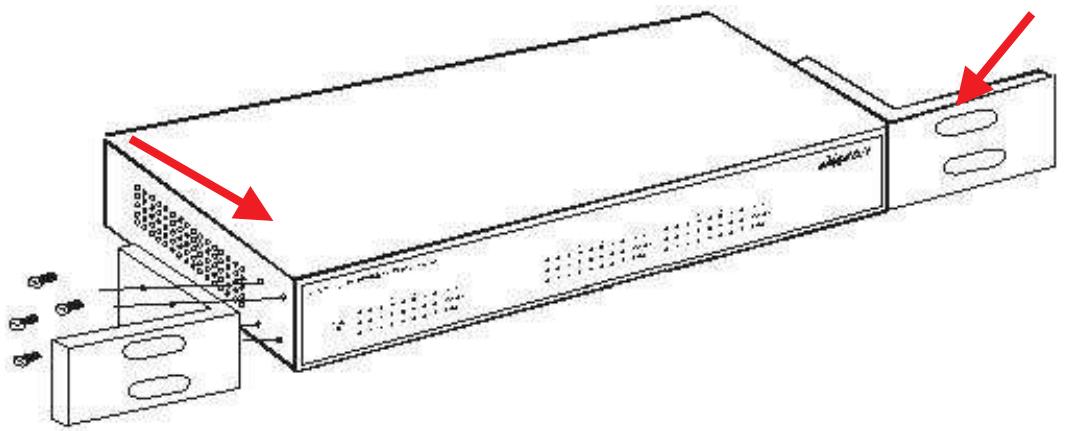
2.2.1 QoS Technology
QoS generally involves the prioritization of network traffic. QoS is comprised of three major components: Classifier, Meter, and Scheduler. Each of these components has a distinct role in ensuring that incoming and outgoing data is managed according to user specifications.
The Classifier analyses incoming packets and marks each one according to configured parameters. The Meter communicates the drop priority to the Scheduler and measures the temporal priorities of the output stream against configured parameters. Finally, the
Scheduler schedules each packet for transmission based on information from both the Classifier and the Meter.
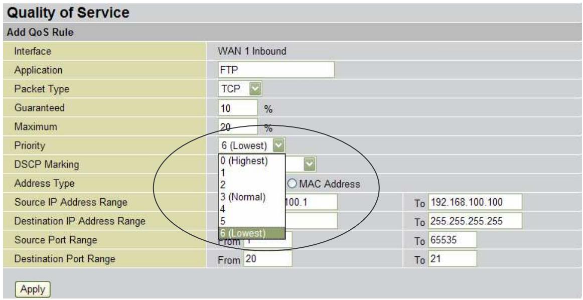
2.2.2 QoS Policies for Different Applications
By setting different QoS policies according to the applications you are running, you can use the RF30 to optimize the bandwidth that is being used on your network.
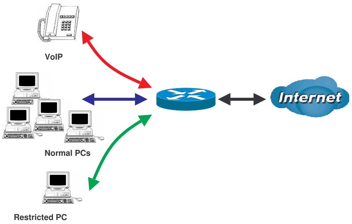
As illustrated in the diagram above, applications such as Voiceover IP (VoIP) require low network latencies to function properly. If bandwidth is being used by other applications such as an FTP server, users using VoIP will experience network lag and/or service interruptions during use. To avoid this scenario, this network has assigned VoIP with a guaranteed bandwidth and higher priority to ensure smooth communications. The FTP server, on the other hand, has been given a maximum bandwidth cap to make sure that regular service to both VoIP and normal Internet applications is uninterrupted.
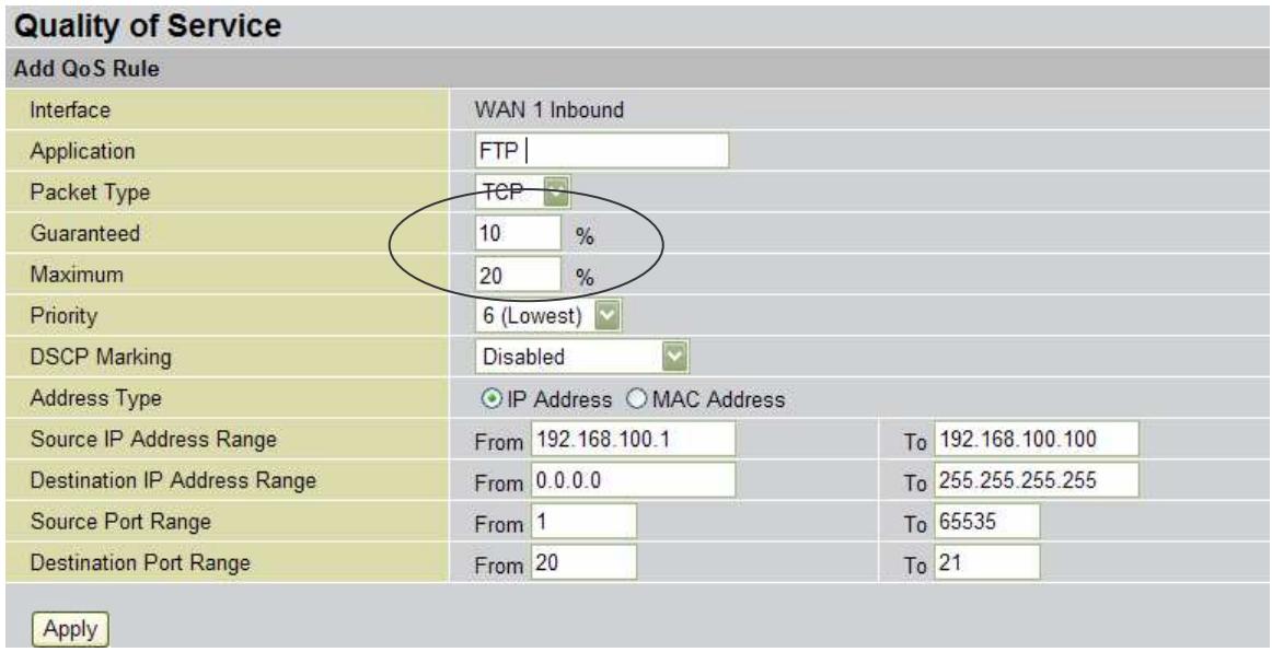
2.2.3 Guaranteed / Maximum Bandwidth
Setting a Guaranteed Bandwidth ensures that a particular service receives a minimum percentage of bandwidth. For example, you can configure the RF30 to reserve 10% of the available bandwidth for a particular computer on the network to transfer files.
Alternatively you can set a Maximum Bandwidth to restrict a particular application to a fixed percentage of the total throughput. Setting a Maximum Bandwidth of 20% for a file sharing program will ensure that no more than 20% of the available bandwidth will be used for file sharing.
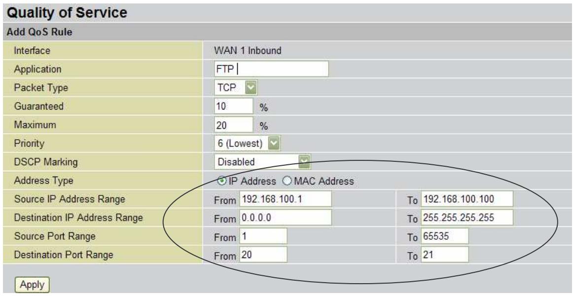
2.2.4 Policy Based Traffic Shaping
Policy Based Traffic Shaping allows you to apply specific traffic policies across a range of IP addresses or ports. This is particularly useful for assigning different policies for different PCs on the network. Policy based traffic shaping lets you better manage your bandwidth, providing reliable Internet and network service to your organization.
2.2.5 Priority Bandwidth Utilization
Assigning priority to a certain service allows the RF30 to give either a higher or lower priority to traffic from this particular service. Assigning a higher priority to an application ensures that it is processed ahead of applications with a lower priority and vice versa.
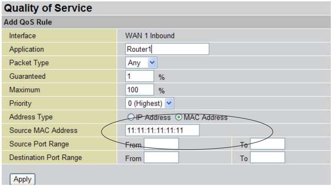
2.2.6 Management by IP or MAC address
The RF30 can also be configured to apply traffic policies based on a particular IP or MAC address. This allows you to quickly assign different traffic policies to a specific computer on the network.
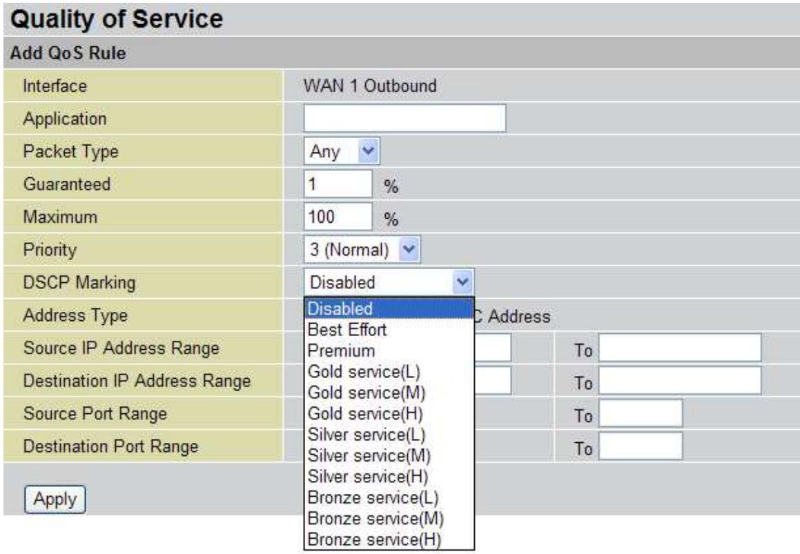
2.2.7 DiffServ (DSCP Marking)
DiffServ (a.k.a. DSCP Marking) allows you to classify traffic based on IP DSCP values. These markings can be used to identify traffic within the network, and other interfaces can match traffic based on the DSCP markings. DSCP markings are used to decide how packets should be treated, and is a useful tool to give precedence to varying types of data.
2.3 Outbound Traffic
This section outlines some of the ways you can use the RF30 to manage outbound traffic.
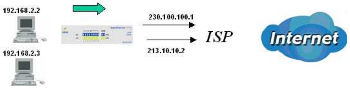
2.3.1 Outbound Fail Over
Configuring the RF30 for Outbound Fail Over allows you to ensure that outgoing traffic is uninterrupted by having the RF30 default to WAN2 should WAN1 fail.
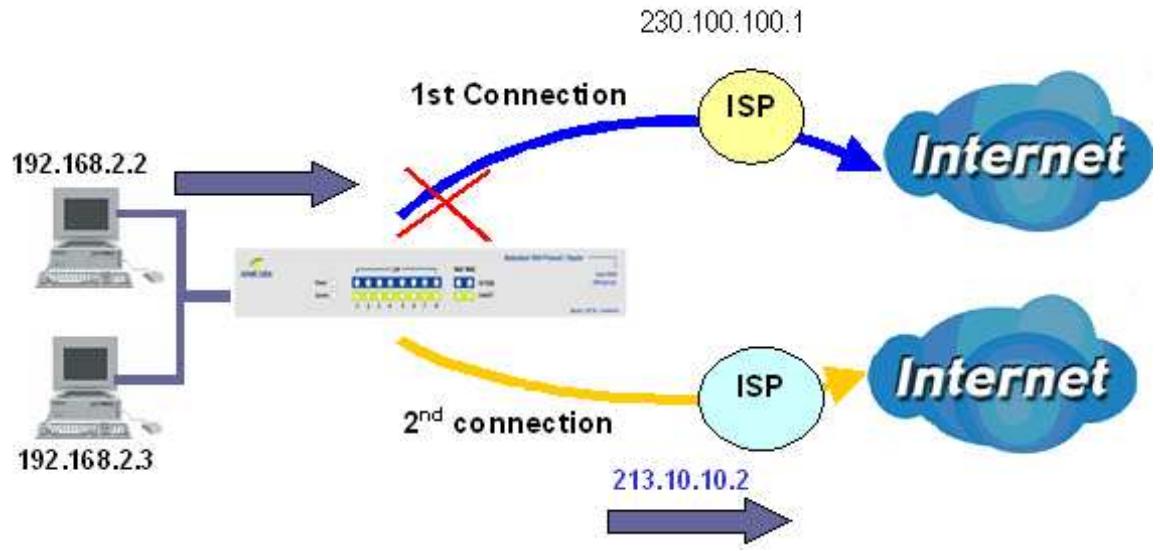
In the above example, PC 1 (IP_192.168.2.2) and PC 2 (IP_192.168.2.3) are connected to the Internet via WAN1 (IP_230.100.100.1) on the RF30. Should WAN1 fail, Outbound Fail Over tells the RF30 to reroute outgoing traffic to WAN2 (IP_213.10.10.2). Configuring your RF30 for Outbound Fail Over provides a more reliable connection for your outgoing traffic.
Please refer to appendix H for example settings.
2.3.2 Outbound Load Balancing
Outbound Load Balancing allows the RF30 to intelligently manage outbound traffic based on the amount of load of each WAN connection.
In the above example, PC 1 (IP_192.168.2.2) and PC 2 (IP_192.168.2.3) are connected to the Internet via WAN1 (IP_230.100.100.1) and WAN2 (IP_213.10.10.2) on the RF30. You can configure the RF30 to balance the load of each WAN port with one of two mechanisms:
- Session (by session/by traffic)
- IP Hash (weight of link capability)
The IP Hash mechanism will ensure that the traffic from the same source IP address and destination IP address will go through the same WAN port. This is useful for some server applications that need to identify the source IP address of the client.
By balancing the load between WAN1 and WAN2, your RF30 can ensure that outbound traffic is efficiently handled by making sure that both ports are equally sharing the load, preventing situations where one port is completely saturated by outbound traffic.
Please refer to appendix H for example settings.
2.4 Inbound Traffic
Learn how the RF30 can handle inbound traffic in the following section.
2.4.1 Inbound Fail Over
Configuring the RF30 for Inbound Fail Over allows you to ensure that incoming traffic is uninterrupted by having the RF30 default to WAN2 should WAN1 fail.
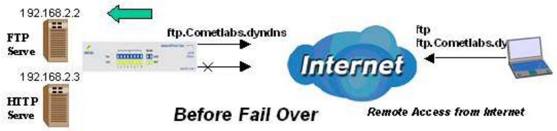
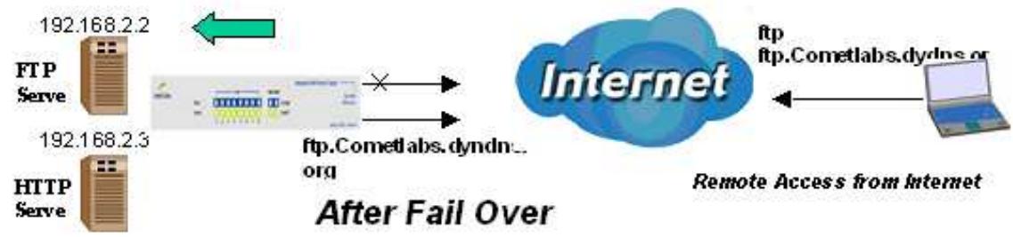
In the above example, an FTP Server (IP_192.168.2.2) and an HTTP Server (IP_192.168.2.3) are connected to the Internet via WAN1 (ftp.Cometlabs.dyndns.org) on the RF30. A remote computer is trying to access these servers via the Internet. Under normal circumstances, the remote computer will gain access to the network via WAN1. Should WAN1 fail, Inbound Fail Over tells the RF30 to reroute incoming traffic to WAN2 by using the Dynamic DNS mechanism. Configuring your RF30 for Inbound Fail Over provides a more reliable connection for your incoming traffic.
Please refer to appendix H for example settings.
2.4.2 Inbound Load Balancing
Inbound Load Balancing allows the RF30 to intelligently manage inbound traffic based on the amount of load of each WAN connection.
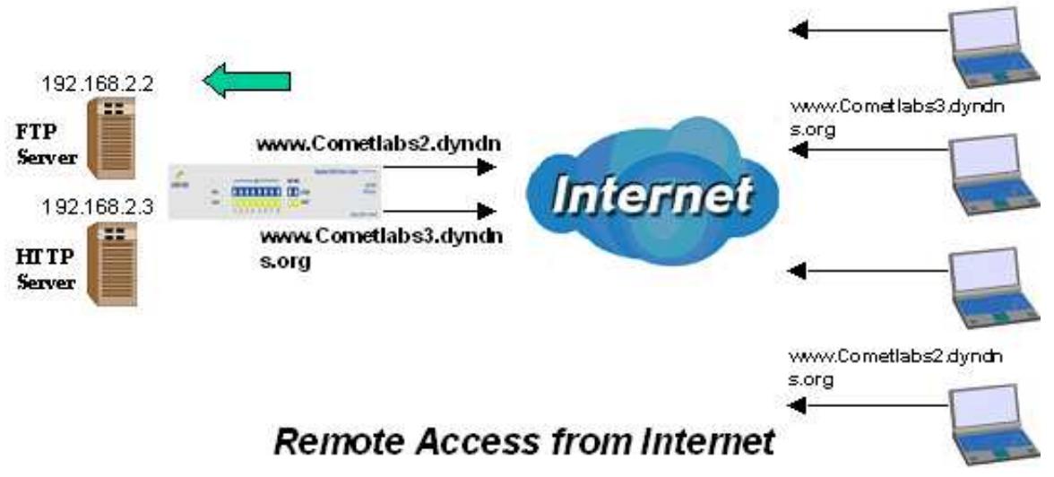
In the above example, an FTP server (IP_192.168.2.2) and an HTTP server (IP_192.168.2.3) are connected to the Internet via WAN1 (www.Cometlabs2.dyndns.org) and WAN2 (www.Cometlabs3.dyndns.org) on the RF30. Remote PCs are attempting to access the servers via the Internet. Using Inbound Load Balancing, the RF30 can direct incoming requests to the correct WAN port based on group assignment. For example, a sales force can be directed to www.Cometlabs2.dyndns.org, while the R&D group can access www.Cometlabs3.dyndns.org. By balancing the load between WAN1 and WAN2, your RF30 can ensure that inbound traffic is efficiently handled with both ports equally sharing the load, preventing situations where service is slow because one port is completely saturated by inbound traffic.
Please refer to appendix H for example settings.
2.5 DNS Inbound
Using DNS Inbound is a great way to intelligently direct network traffic.
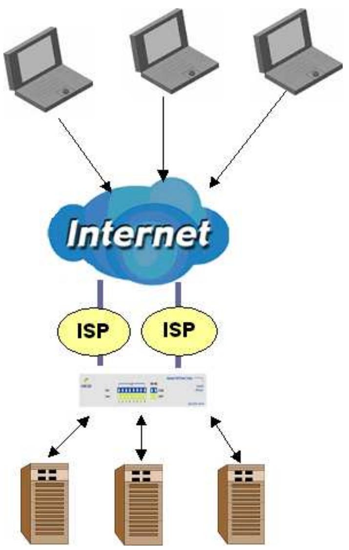
DNS Inbound is a three step process. First, a DNS request is made to the router via a remote PC. The RF30, based on settings specified by the user, will direct the requesting PC to the correct WAN port by replying the selected WAN IP address through the built-in DNS server. The remote PC then accesses the network via the specified WAN port. How the RF30 directs this traffic through the built-in DNS server depends on whether it is configured for Fail Over or Load Balancing.
Learn how to make DNS Inbound on the RF30 work for you in the following section.
2.5.1 DNS Inbound Fail Over
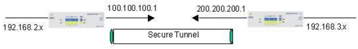
The RF30 can be configured to reply the WAN2 IP address for the DNS domain name request should WAN1 fail.
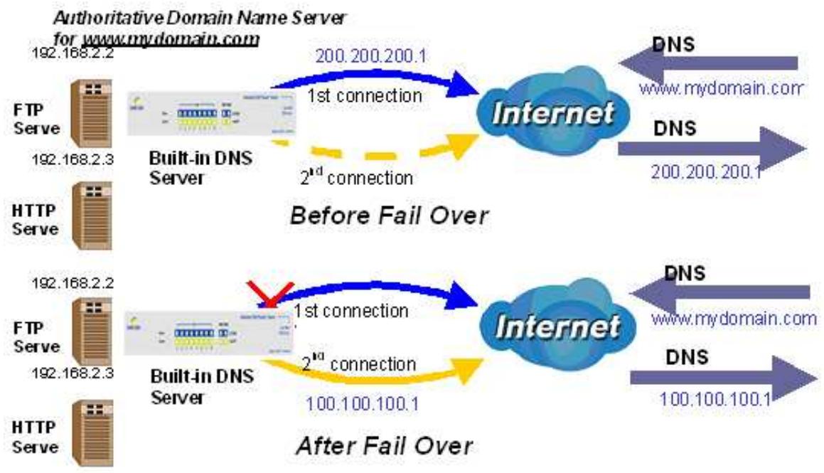
In the above example, an FTP Server (IP_192.168.2.2) and an HTTP Server (IP_192.168.2.3) are connected to the Internet via WAN1 (IP_200.200.200.1) on the RF30. A remote computer is trying to access these servers via the Internet, and makes a DNS request. The DNS request (www.mydomain.com) will be sent through WAN1 (200.200.200.1) to the built-in DNS server. The DNS server will reply 200.200.200.1 because this is the only active WAN port. Should WAN1 fail, the RF30 will instead reply with WAN2's IP address (100.100.100.1), and the remote PC will gain access to the network via WAN2. By configuring the RF30 for DNS Inbound Fail Over, incoming requests will enjoy increased reliability when accessing your network.
Please refer to appendix H for example settings.
2.5.2 DNS Inbound Load Balancing
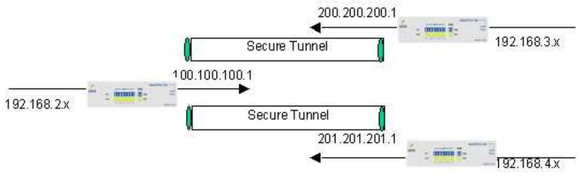
DNS Inbound Load Balancing allows the RF30 to intelligently manage inbound traffic based on the amount of load of each WAN connection by assigning the IP address with the lowest traffic load to incoming requests.
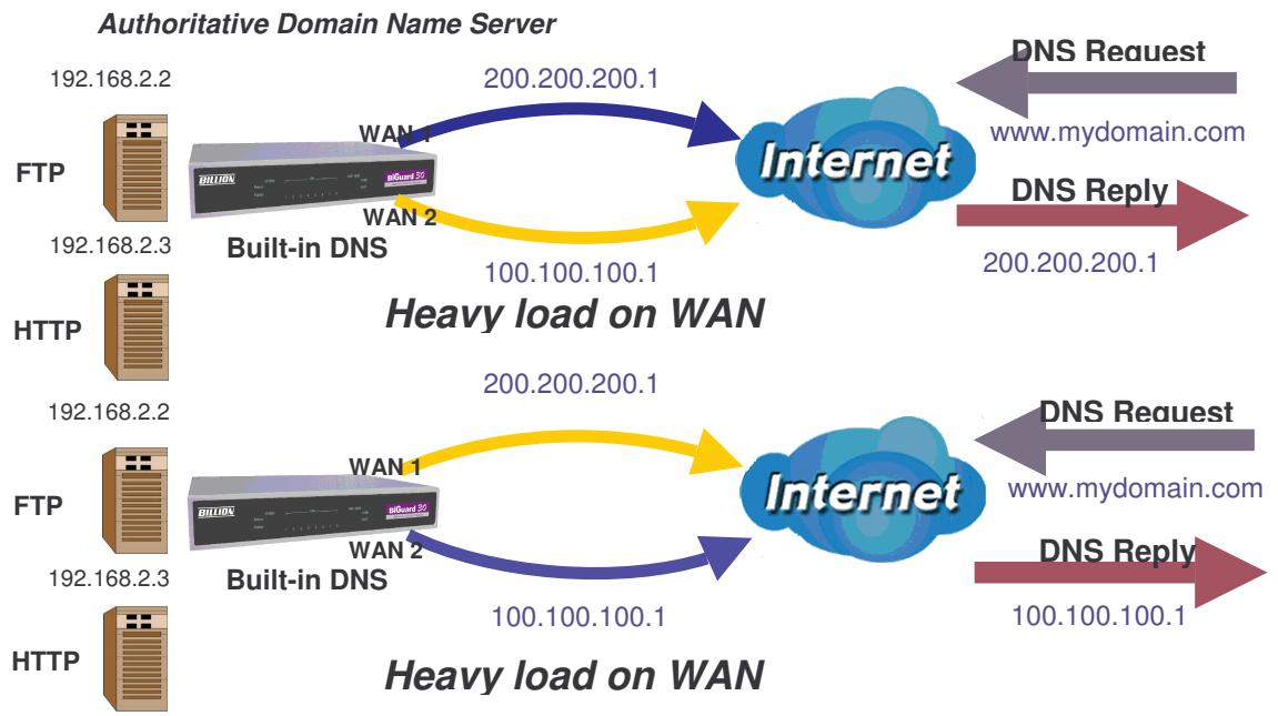
In the above example, an FTP server (IP_192.168.2.2) and an HTTP server (IP_192.168.2.3) are connected to the Internet via WAN1 (IP_200.200.200.1) and WAN2 (IP_100.100.100.1) on the RF30. Remote PCs are attempting to access the servers via the Internet by making a DNS request, entering a URL (www.mydomain.com). Using a load balancing algorithm, the RF30 can direct incoming requests to either WAN port based on the amount of load each WAN port is currently experiencing. If WAN2 is experiencing a heavy load, the RF30 responds to incoming DNS requests with WAN1. By balancing the load between WAN1 and WAN2, your RF30 can ensure that inbound traffic is efficiently handled, making sure that both ports are equally sharing the load and preventing situations where service is slow because one port is completely saturated by inbound traffic.
Please refer to appendix H for example settings.
A typical scenario of how traffic is directed with DNS Inbound Load Balancing is illustrated below:
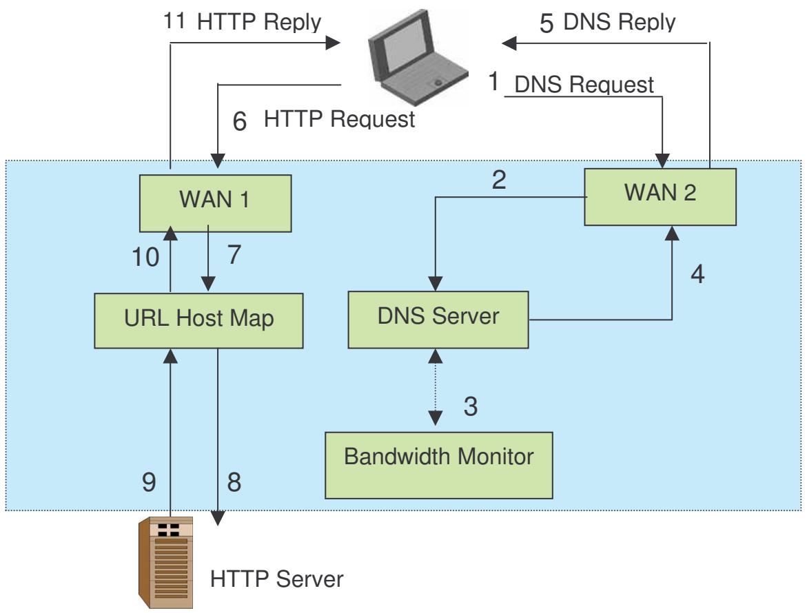
In the example above, the client is making a DNS request. The request is sent to the DNS server of the RF30 through WAN2 (1). WAN2 will route this request to the embedded DNS server of the RF30 (2). The RF30 will analyze the bandwidth of both WAN1 and WAN2 and decide which WAN IP to reply to the request (3). After the decision is made, the RF30 will route the DNS reply to the user through WAN2 (4). The user will receive the DNS reply with the IP address of WAN1 (5). The browser will initiate an HTTP request to the WAN1 IP address (6). The HTTP request will be send to the RF30's URL Host Map (7). The Host Map will then redirect the HTTP request to the HTTP server (8). The HTTP server will reply (9). The URL Host Map will route the packet through WAN1 to the user (10). Finally, the client will receive an HTTP reply packet (11).
2.6 Virtual Private Networking
A Virtual Private Network (VPN) enables you to send data between two computers across a shared or public network in a manner that emulates the properties of a point-to-point private link. As such, it is perfect for connecting branch offices to headquarters across the Internet in a secure fashion.
The following section discusses Virtual Private Networking with the RF30.
2.6.1 General VPN Setup
There are typically three different VPN scenarios. The first is a Gateway to Gateway setup, where two remote gateways communicate over the Internet via a secure tunnel.
The next type of VPN setup is the Gateway to Multiple Gateway setup, where one gateway (Headquarters) is communicating with multiple gateways (Branch Offices) over the Internet. As with all VPNs, data is kept secure with secure tunnels.
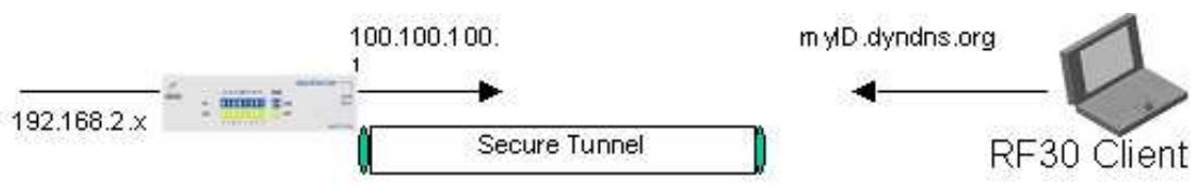
The final type of VPN setup is the Client to Gateway. A good example of where this can be applied is when a remote sales person accesses the corporate network over a secure VPN tunnel.
VPN provide a flexible, cost-efficient, and reliable way for companies of all sizes to stay connected. One of the most important steps in setting up a VPN is proper planning. The following sections demonstrate the various ways of using the RF30 to setup your VPN.
2.6.2 VPN Planning - Fail Over
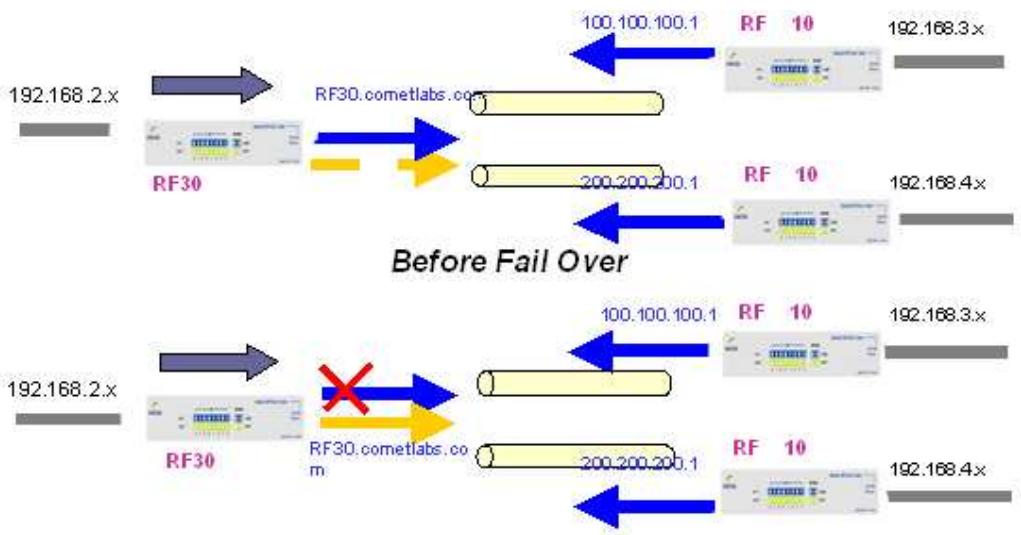
Configuring your VPN with Fail Over allows the RF30 to automatically default to WAN2 should WAN1 fail.
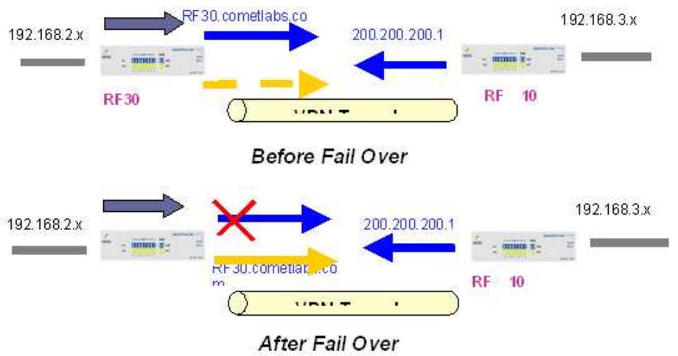
Because the dynamic domain name RF30.cometlabs.com is configured for both WAN1 and WAN2, the active WAN port will announce the domain name through the WAN IP address. The remote gateway will then be able to connect to the VPN through the domain name.
In this Gateway to Gateway example, the RF30 is communicating to a remote gateway using WAN1 through a secure VPN tunnel. Should WAN1 fail, outbound traffic from the RF30 will automatically be redirected to WAN2. This process is completely transparent to the remote gateway, as the RF30 will automatically update the domain name (RF30.cometlabs.com) with the WAN2 IP address.
Configuring a Gateway to Multiple Gateway setup with Fail Over is similar, as shown below:
Configuring the RF30 for Fail Over provides added reliability to your VPN.
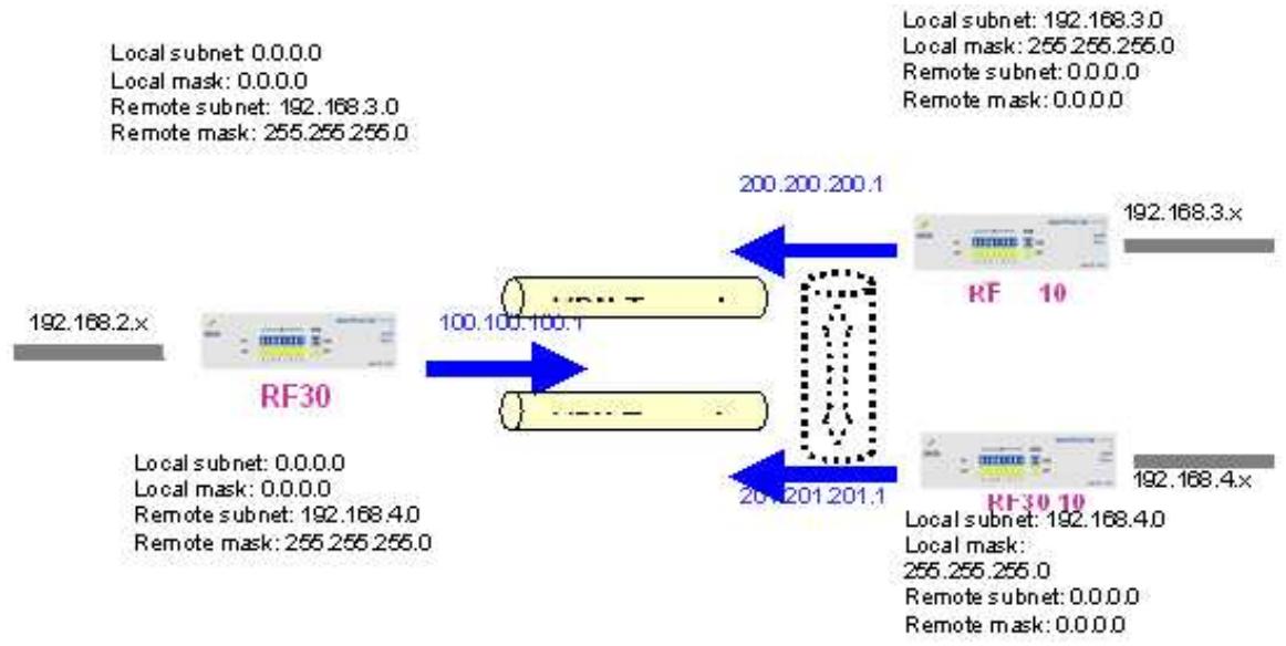
2.6.3 Concentrator
The VPN Concentrator provides an easy way for branch offices to connect to headquarters through a VPN tunnel. All branch office traffic will be redirected to the VPN tunnel to headquarters with the exception of LAN-side traffic. This way, all branch offices can connect to each other through headquarters via the headquarters' firewall management. You can also configure the RF30 to function as a VPN Concentrator:
Please refer to appendix H for example settings.
Chapter 3: Getting Started
3.1 Overview
The RF30 is designed to be a powerful and flexible network device that is also easy to use. With an intuitive web-based configuration, the RF30 allows you to administer your network via virtually any Java-enabled web browser and is fully compatible with Linux, Mac OS, and Windows 98/Me/NT/2000/XP operating systems.
The following chapter takes you through the very first steps to configuring your network for the RF30. Take a look and see how easy it is to get your network up and running.
3.2 Before You Begin
The RF30 is a flexible and powerful networking device. To simplify the configuration process and increase the efficiency of your network, consider the following items before setting up your network for the first time:
1. Plan your network
Decide whether you are going to use one or both WAN ports. For one WAN port, you may need a fully qualified domain name either for convenience or if you have a dynamic IP address. If you are going to use both WAN ports, determine whether you are going to use them in fail over mode for increased network reliability or load balancing mode for maximum bandwidth efficiency. See
Chapter 2: Router Applications for more information.
2. Set up your accounts
Have access to the Internet and locate the Internet Service Provider (ISP) configuration information. Each RF30 WAN port must be configured separately, whether you are using a separate ISP for each WAN port or are having the traffic of both WAN ports routed through the same ISP.
3. Determine your network management approach
The RF30 is capable of remote management. However, this feature is not active by default. If you reset the device, remote administration must be enabled again. If you decide to manage your network remotely, be sure to change the default password to something more secure.
- Prepare to physically connect the RF30 to Cable or DSL modems and a computer.
Be sure to also review the SafetyWarnings located in the preface of this manual before working with your RF30.
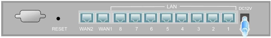
3.3 Connecting Your Router
Connecting the RF30 is an easy three-step process:
- Connect the RF30 to your LAN by connecting Ethernet cables from your networked PCs to the LAN ports on the router. Connect the RF30 to your broadband Internet connection via router's WAN port.
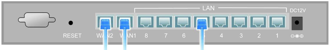
- Plug the RF30 to an AC outlet with the included AC Power Adapter.
- Ensure that the Power and WAN LEDs are solidly lit, and that on any LAN port that has an Ethernet cable plugged in the LED is also solidly lit. The Status LED will remain solid as the device boots. Once the boot sequence is complete, the LED will shut off, indicating that the RF30 is ready.
If the router does not power on, please refer to Chapter 5: Troubleshooting for possible solutions.
3.4 Configuring PCs for TCP/IP Networking
Now that your RF30 is connected properly to your network, it's time to configure your networked PCs for TCP/IP networking.
In order for your networked PCs to communicate with your router, they must have the following characteristics:
- Have a properly installed and functioning Ethernet Network Interface Card (NIC).
- Be connected to the RF30, either directly or through an external repeater hub via an Ethernet cable.
- Have TCP/IP installed and configured with an IP address.
The IP address for each PC may be a fixed IP address or one that is obtained from a DHCP server. If using a fixed IP address, it is important to remember that it must be in the same subnet as the router. The default IP address of the RF30 is 192.168.1.254 with a subnet mask of 255.255.255.0. Using the default configuration, networked PCs must reside in the same subnet, and have an IP address in the range of 192.168.1.1 to 192.168.1.253. However, you'll find that the quickest and easiest way to configure the IP addresses for your PCs is to obtain the IP addresses automatically by using the router as a DHCP server.
If you are unable to access the web configuration interface, check to see if you have any software-based firewalls installed on your PCs, as they can cause problems accessing the 192.168.1.254 IP address of the RF30.
The following sections outline how to set up your PCs for TCP/IP networking. Refer to the applicable section for your PC's operating system.
3.4.1 Overview
Before you begin, make sure that the TCP/IP protocol and a functioning Ethernet network adapter is installed on each of your PCs.
The following operating systems already include the necessary software components you need to install TCP/IP on your PCs:
- Windows 95/98/Me/NT/2000/XP
- Mac OS 7 and later
If you are using Windows 3.1, you must purchase a third-party TCP/IP application package.
Any TCP/IP capable workstation can be used to communicate with or through the RF30. To configure other types of workstations, please consult the manufacturer's documentation.
3.4.2 Windows XP
3.4.2.1 Configuring
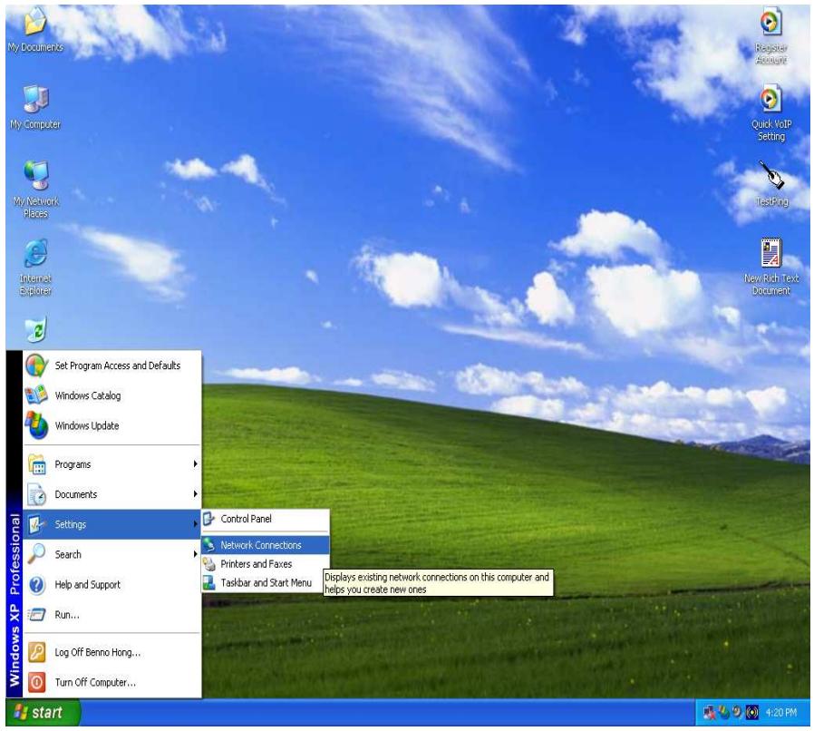
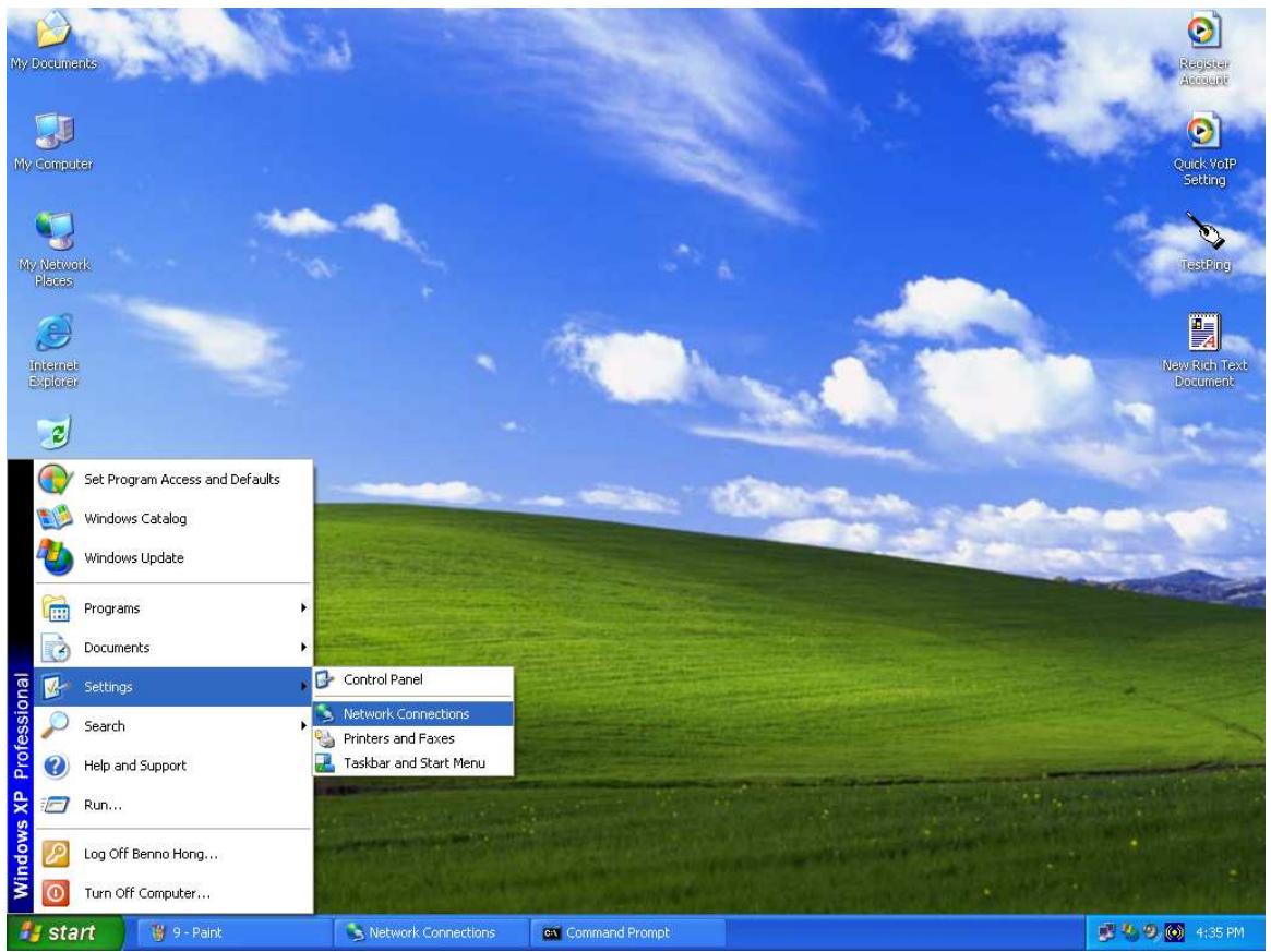
- Select Start > Settings > Network Connections.
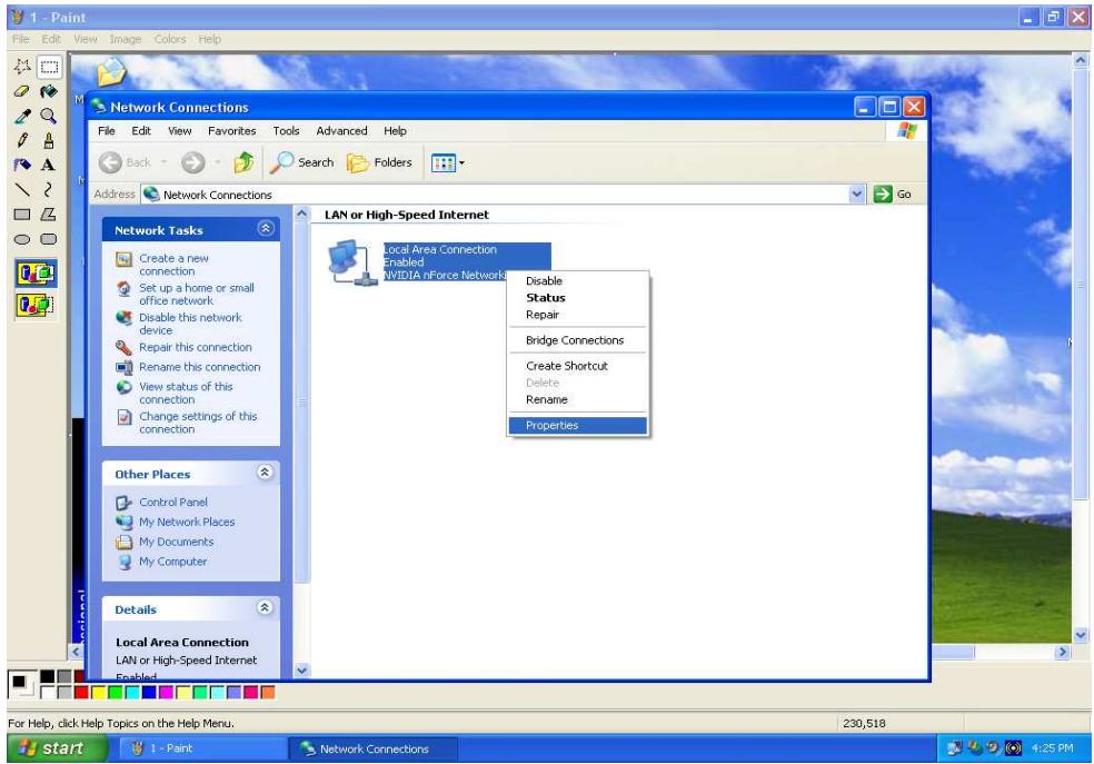
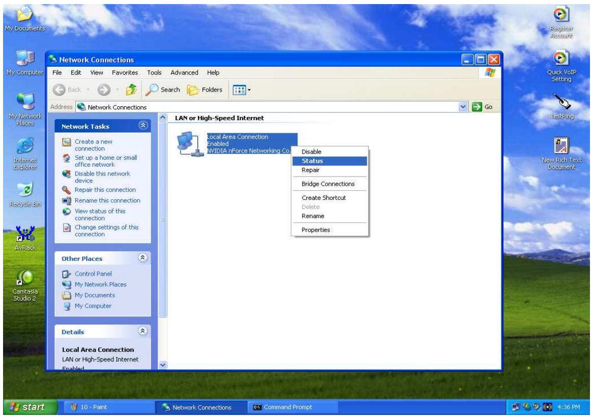
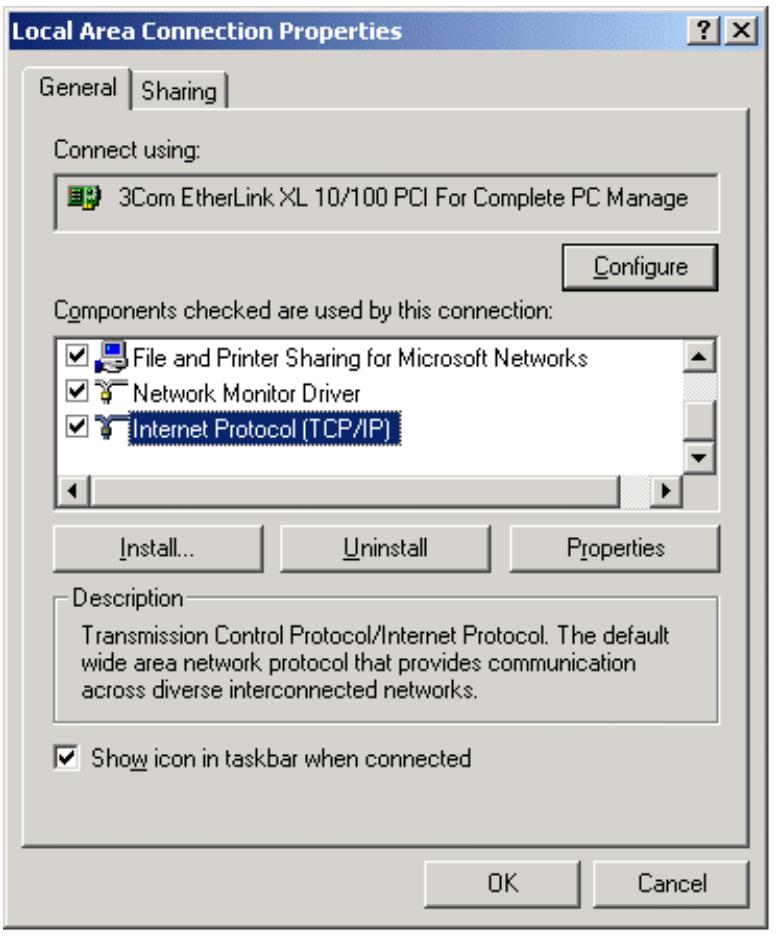
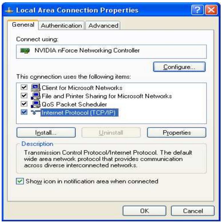
- In the Network Connections window, right-click Local Area Connection and select Properties.
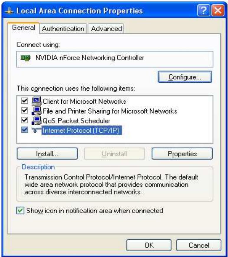
- Select Internet Protocol (TCP/IP) and click Properties.
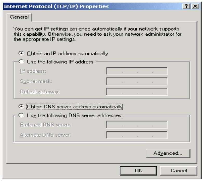
4a. To have your PC obtain an IP address automatically, select the Obtain an IP address automatically and Obtain DNS server address automatically radio buttons.
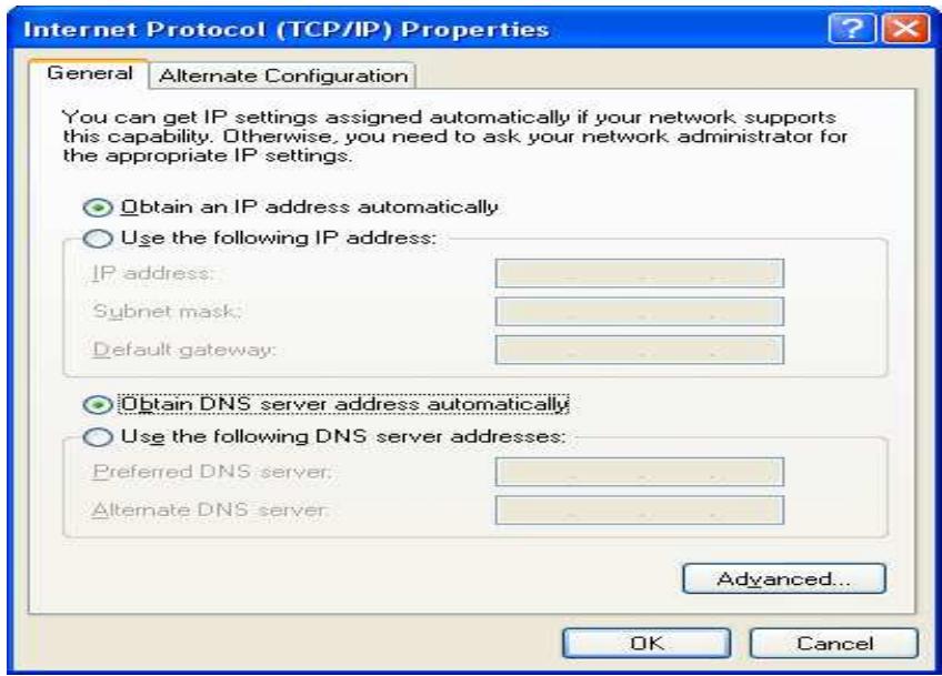
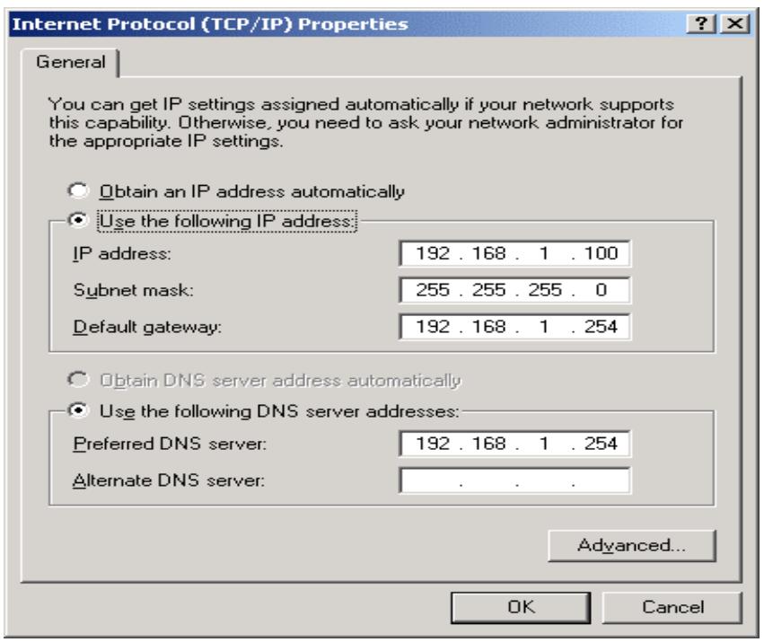
4b. To manually assign your PC a fixed IP address, select the Use the following IP address radio button and enter your desired IP address, subnet mask, and default gateway in the blanks provided. Remember that your PC must reside in the same subnet mask as the router. To designate a DNS server, select the Use the following DNS server and fill in the preferred DNS address.
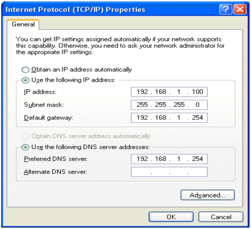
- Click OK to finish the configuration.
3.4.2.2 Verifying Settings
To verify your settings using a command prompt:
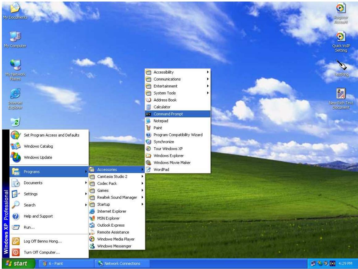
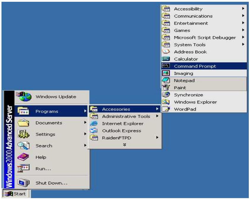
- Click Start > Programs > Accessories > Command Prompt.
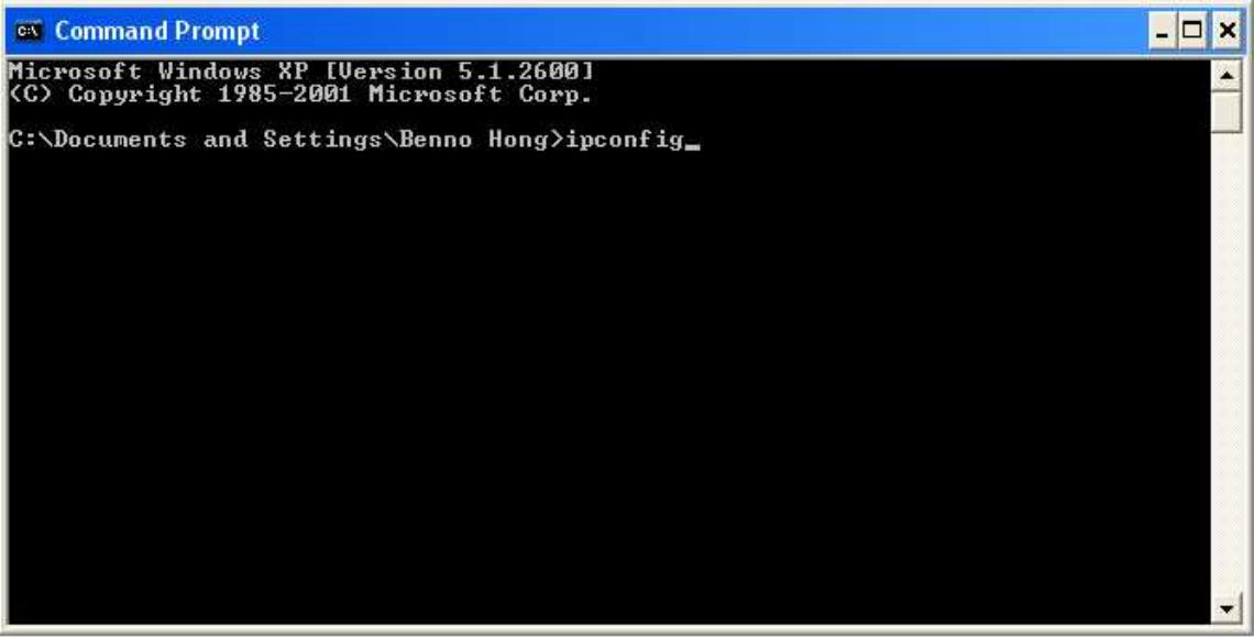
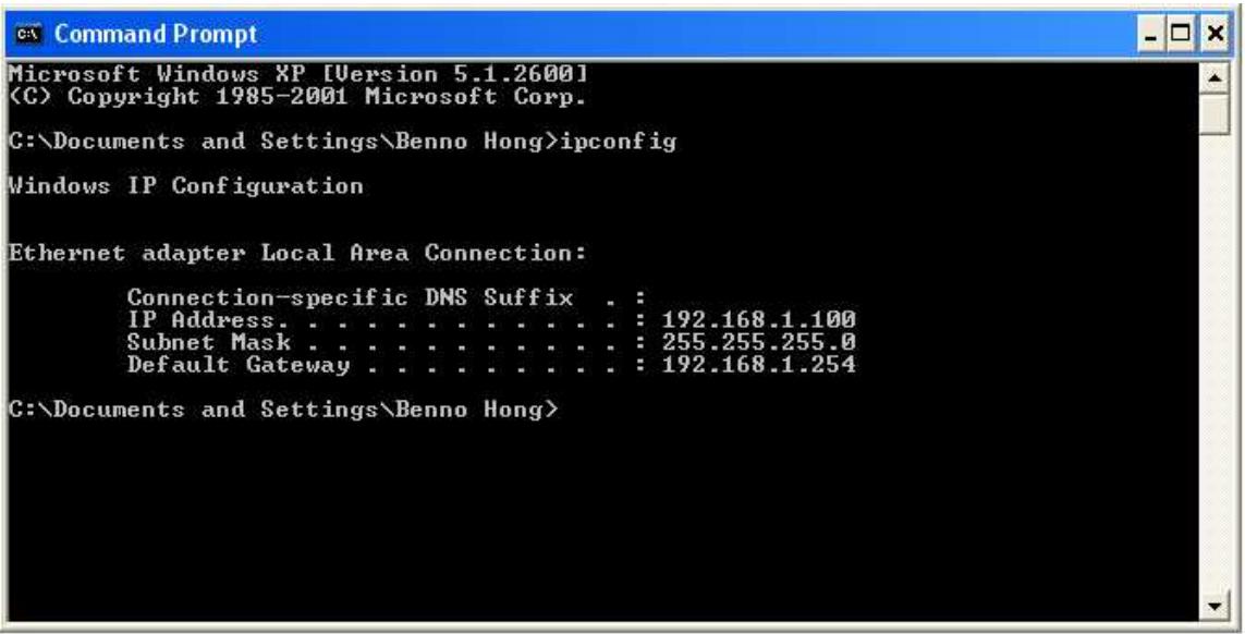
- In the Command Prompt window, type ipconfig and then press ENTER.
If you are using the RF30's default settings, your PC should have:
- An IP address between 192.168.1.1 and 192.168.1.253
- A subnet mask of 255.255.255.0
To verify your settings using the Windows XP GUI:
- Click Start > Settings > Network Connections.
- Right click one of the network connections listed and select Status from the pop-up menu.
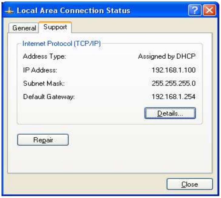
- Click the Support tab.
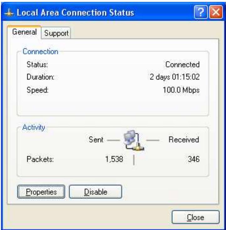
If you are using the RF30's default settings, your PC should:
- Have an IP address between 192.168.1.1 and 192.168.1.253
- Have a subnet mask of 255.255.255.0
3.4.3 Windows 2000
3.4.3.1 Configuring
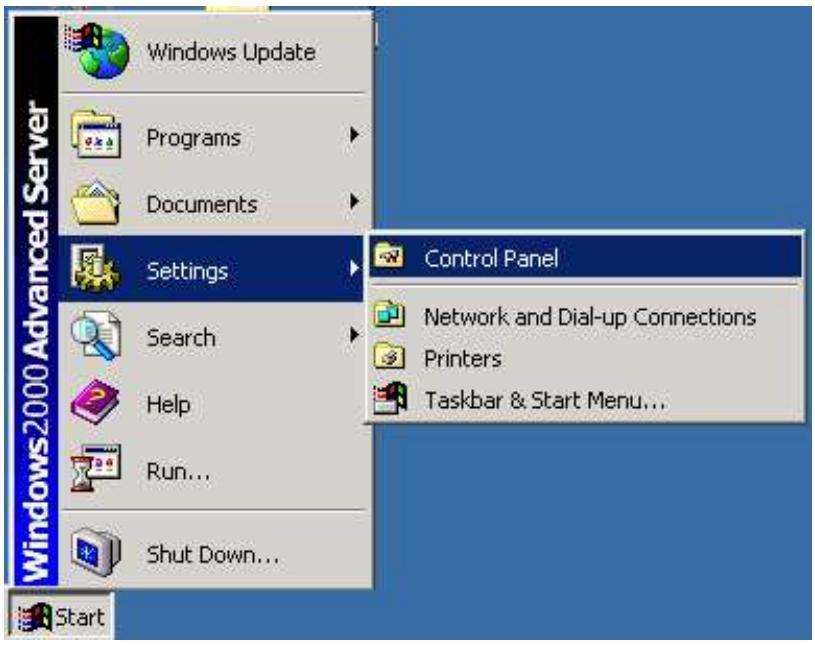
- Select Start > Settings > Control Panel.
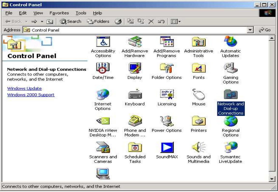
- In the Control Panel window, double-click Network and Dial-up Connections.
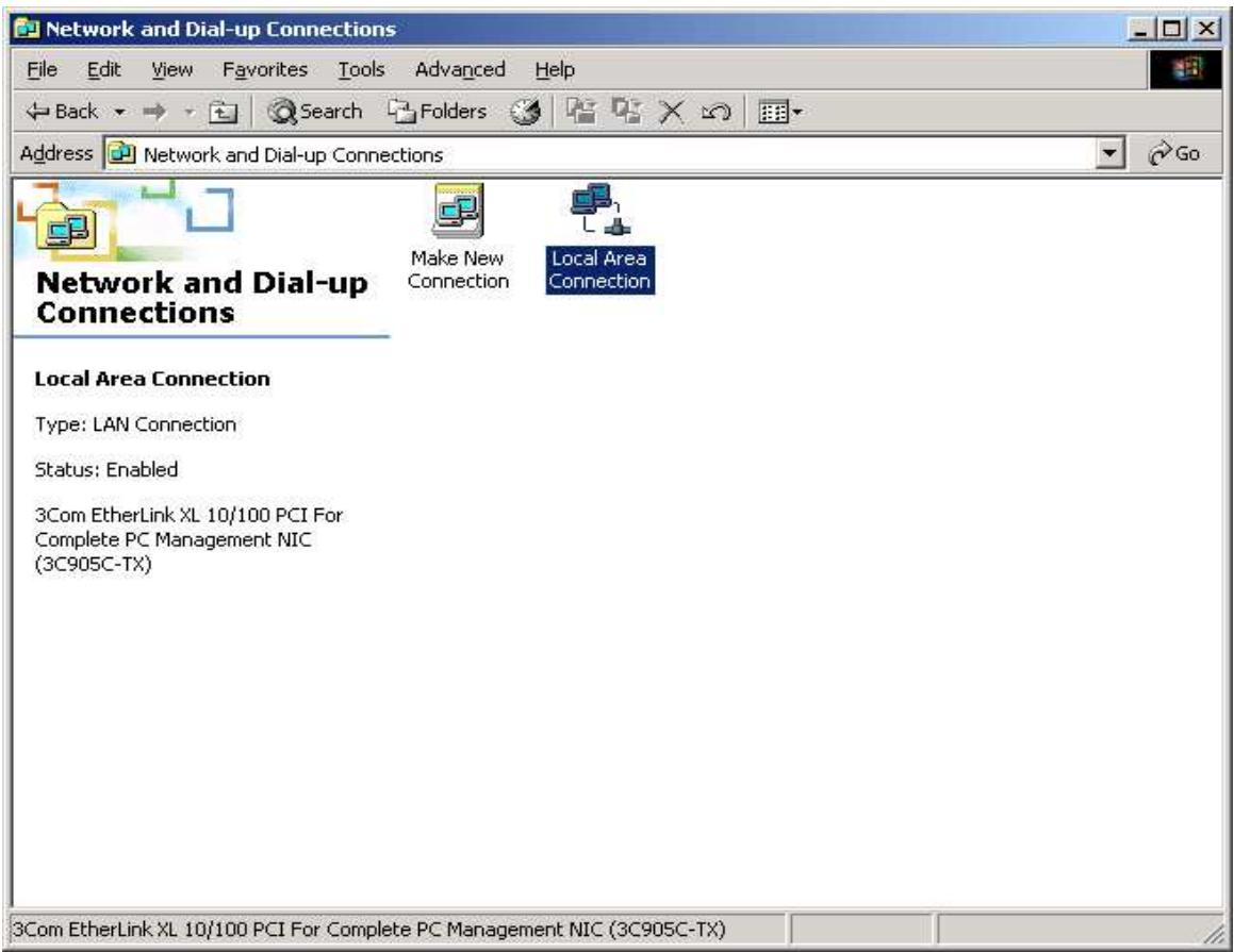
- In Network and Dial-up Connections, double-click Local Area Connection.
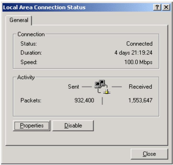
- In the Local Area Connection window, click Properties.
- Select Internet Protocol (TCP/IP) and click Properties.
6a. To have your PC obtain an IP address automatically, select the Obtain an IP address automatically and Obtain DNS server address automatically radio buttons.
6b. To manually assign your PC a fixed IP address, select the Use the following IP address radio button and enter your desired IP address, subnet mask, and default gateway in the blanks provided. Remember that your PC must reside in the same subnet mask as the router. To designate a DNS server, select the Use the following DNS server and fill in the preferred DNS address.
- Click OK to finish the configuration.
3.4.3.2 Verifying Settings
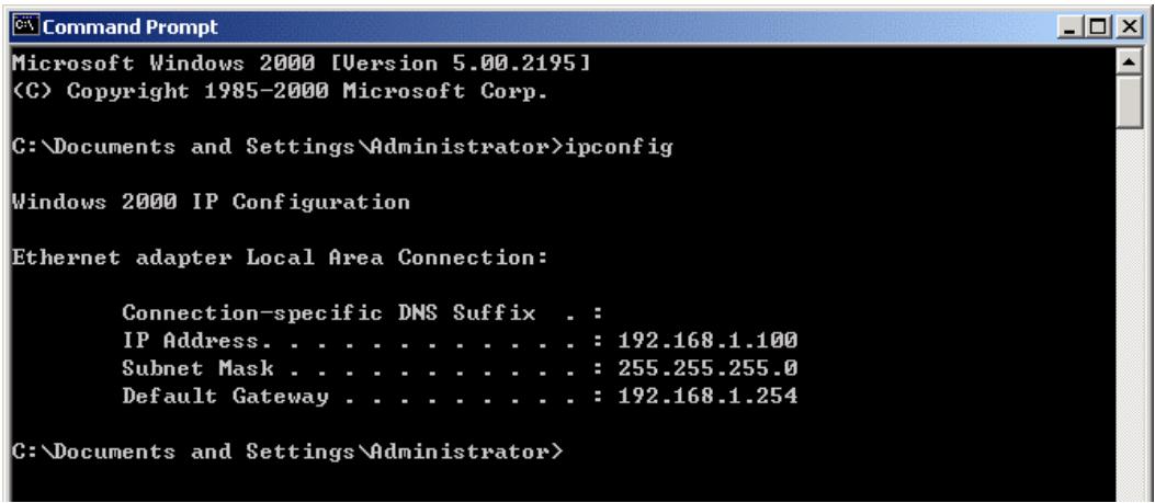
- Click Start > Programs > Accessories > Command Prompt.
- In the Command Prompt window, type ipconfig and then press ENTER.
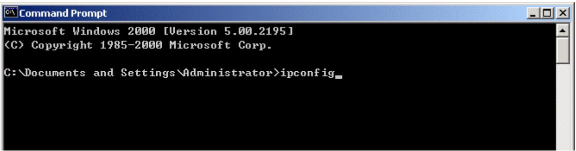
If you are using the RF30's default settings, your PC should have:
-
An IP address between 192.168.1.1 and 192.168.1.253
-
A subnet mask of 255.255.255.0
3.4.4 Windows 98 / Me
3.4.4.1 Installing Components
To prepare Windows 98/Me PCs for TCP/IP networking, you may need to manually install TCP/IP on each PC. To do this, follow the steps below. Be sure to have your Windows CD handy, as you may need to insert it during the installation process.
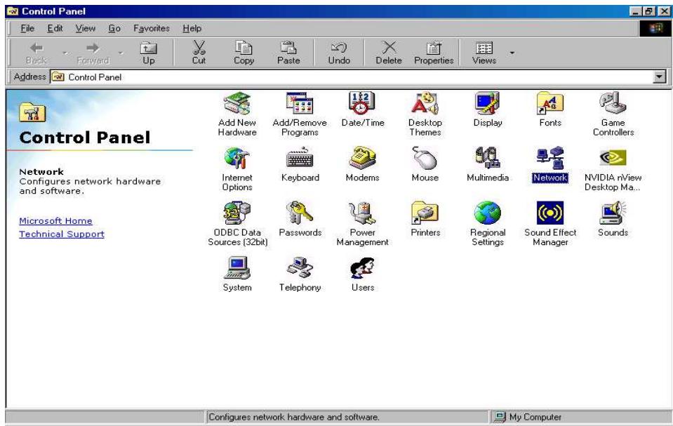
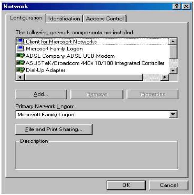
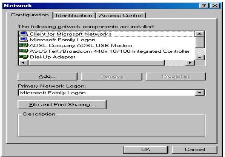
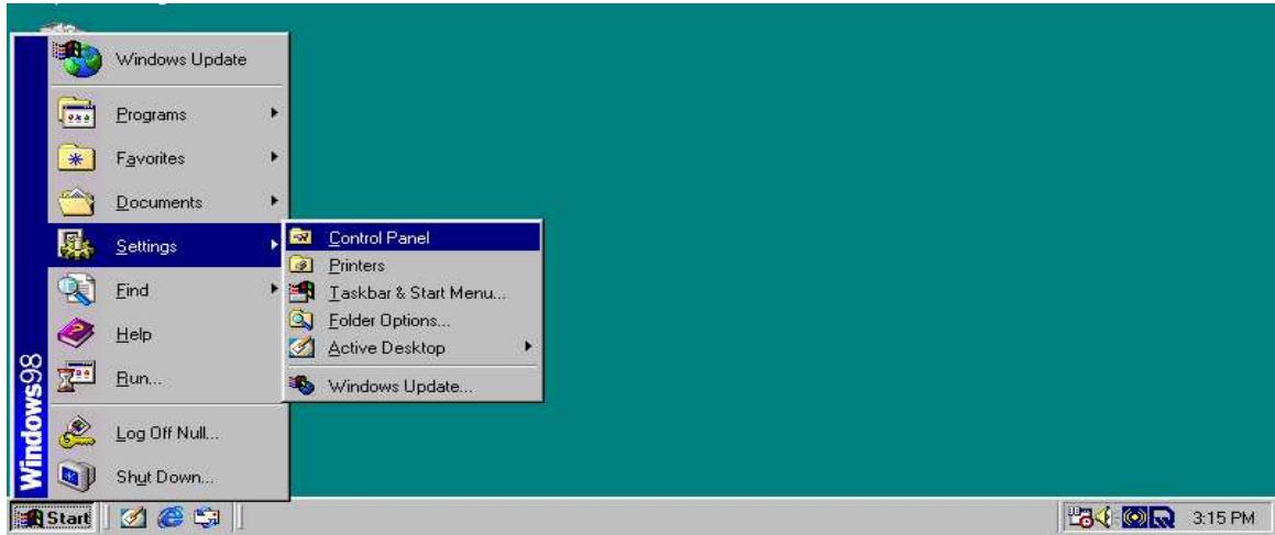
- On the Windows taskbar, select Start > Settings > Control Panel.
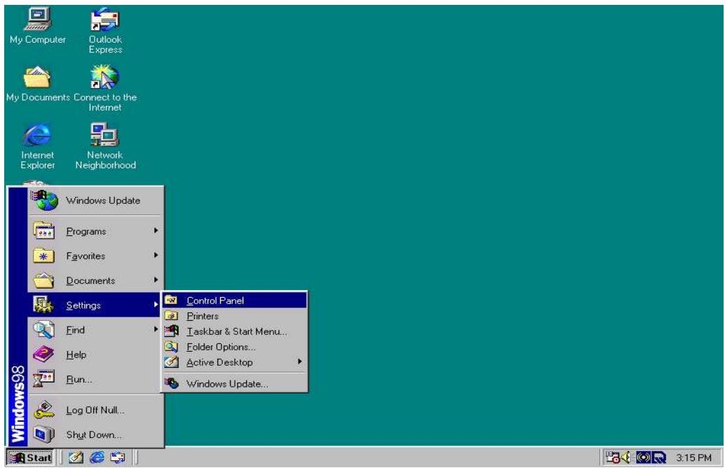
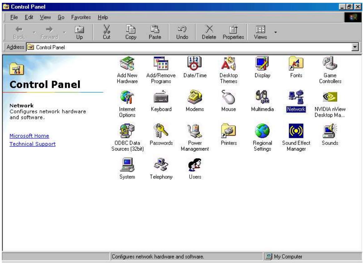
- Double-click the Network icon. The Network window displays a list of installed components.

You must have the following installed:
- An Ethernet adapter
- TCP/IP protocol
- Client for Microsoft Networks
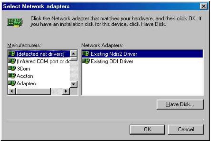
If you need to install a new Ethernet adapter, follow these steps:
a. Click Add.
b. Select Adapter, then Add.
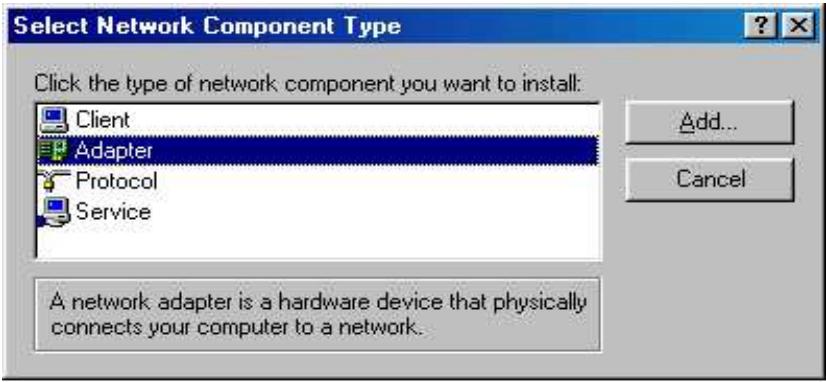
c. Select the manufacturer and model of your Ethernet adapter, then click OK.
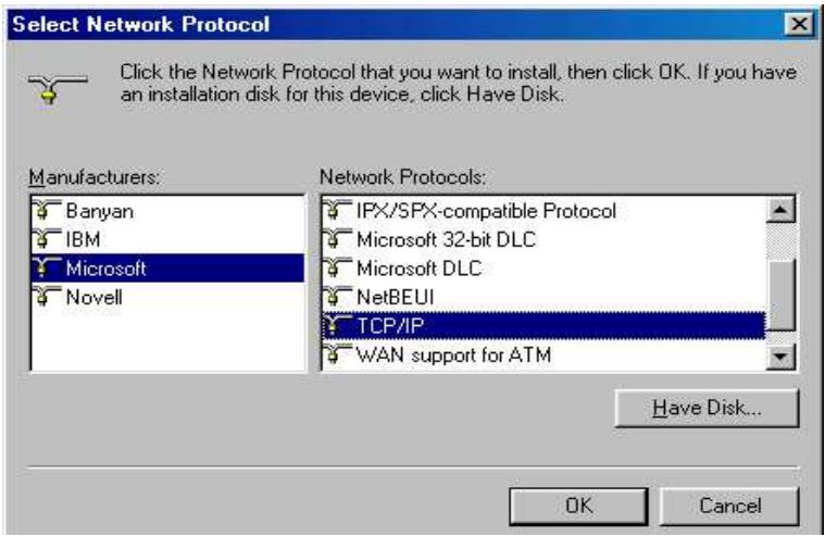
If you need TCP/IP:
a. Click Add.
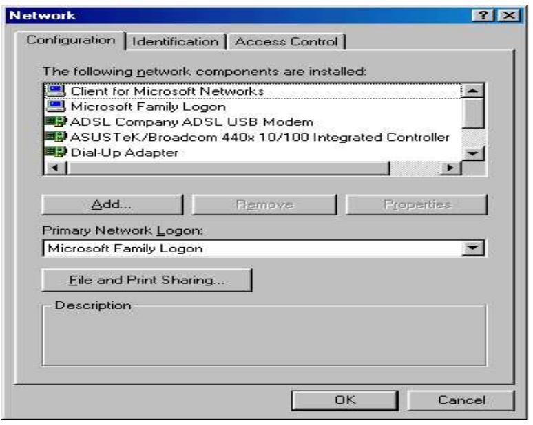
b. Select Protocol, then click Add.
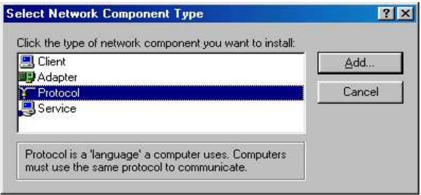
c. Select Microsoft. TCP/IP, then OK.
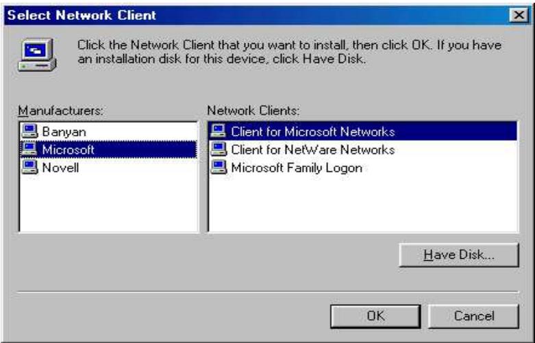
If you need Client for Microsoft Networks:
a. Click Add.
b. Select Client, then click Add.
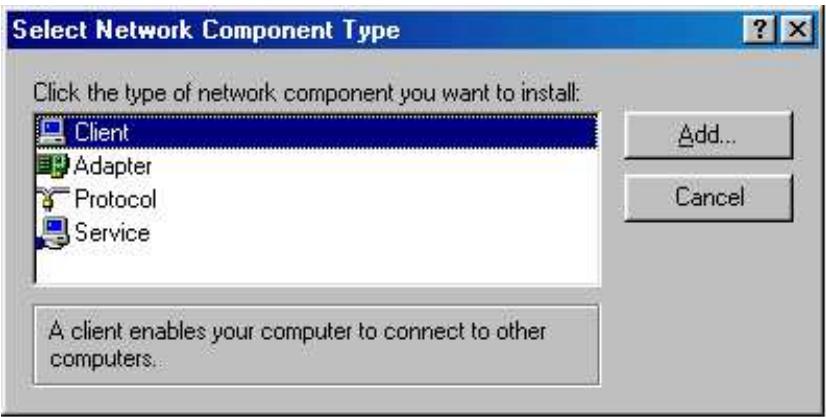
c. Select Microsoft. Client for Microsoft Networks, and then click OK.
- Restart your PC to apply your changes.
3.4.4.2 Configuring
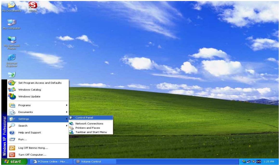
- Select Start > Settings > Control Panel.
- In the Control Panel, double-click Network and choose the Configuration tab.
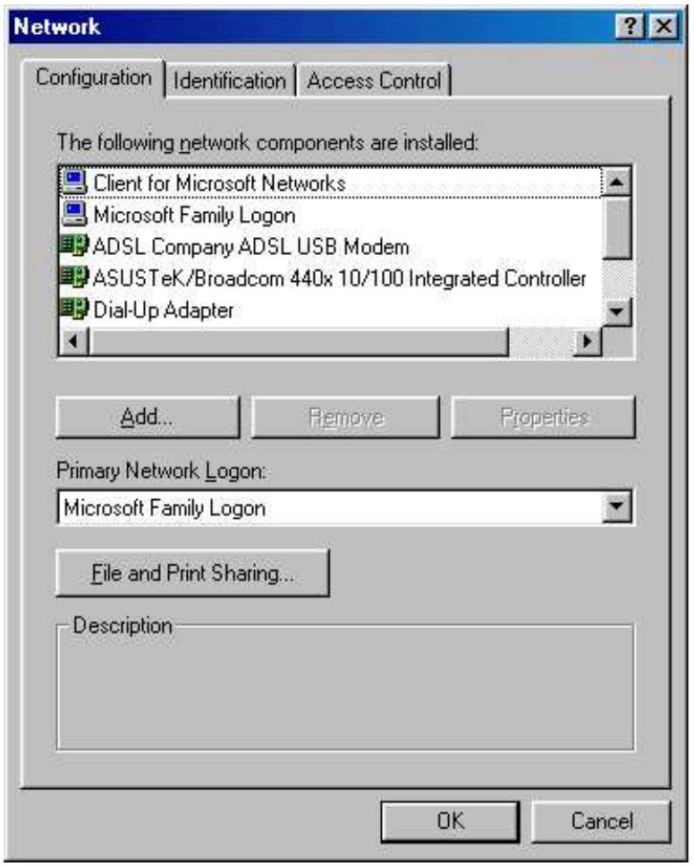
- Select TCP / IP > ASUSTek or the name of any Network Interface Card (NIC) in your PC and click Properties.
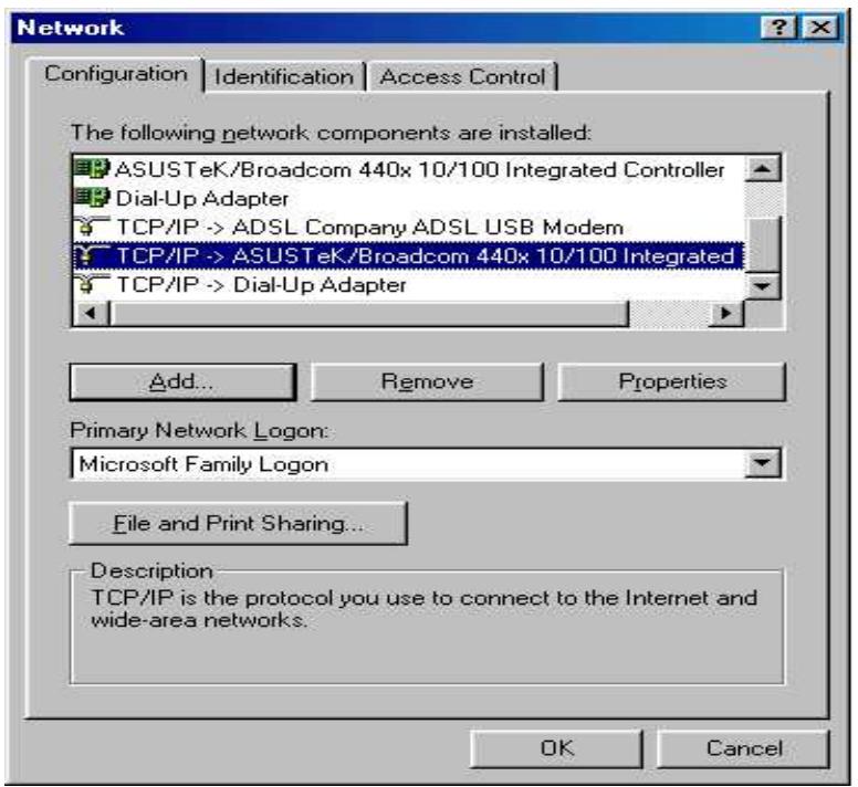
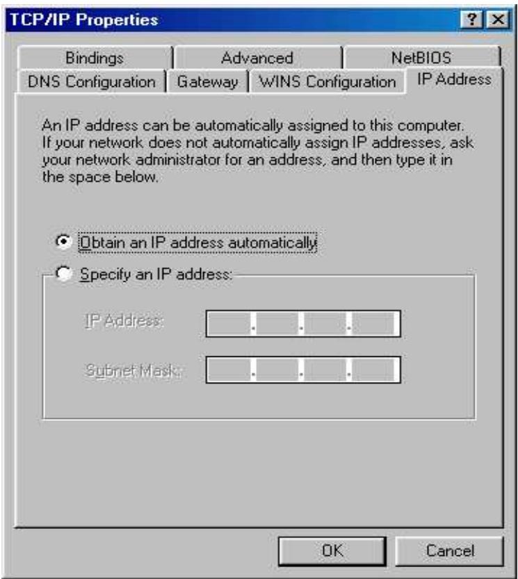
- Select the IP Address tab and click the Obtain an IP address automatically radio button.
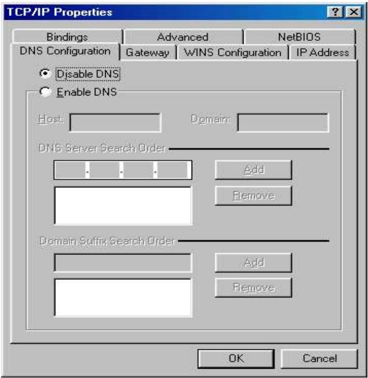
- Select the DNS Configuration tab and select the Disable DNS radio button.
- Click OK to apply the configuration.

3.4.4.3 Verifying Settings
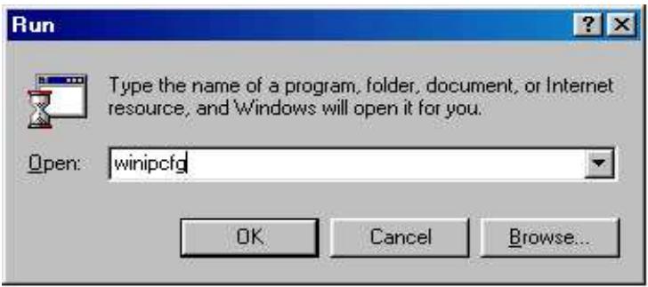
To check the TCP/IP configuration, use the winipcfg.exe utility:
1. Select Start > Run.
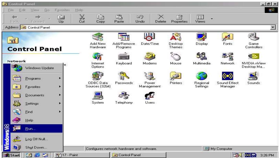
- Type winipcfg, and then click OK.
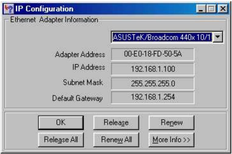
- From the drop-down box, select your Ethernet adapter.
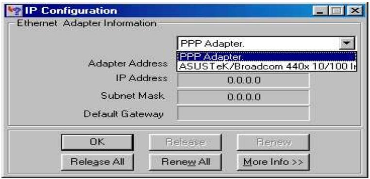
The window is updated to show your settings. Using the default RF30 settings, your PC should have:
- An IP address between 192.168.1.1 and 192.168.1.253
- A subnet mask of 255.255.255.0
-A default gateway of 192.168.1.254
3.5 Factory Default Settings
Before configuring your RF30, you need to know the following default settings:
Web Interface:
Username: admin
Password: admin
LAN Device IP Settings:
IP Address: 192.168.1.254
Subnet Mask: 255.255.255.0
ISP setting in WAN site:
Obtain an IP Address automatically (DHCP Client)
DHCP server:
DHCP server is enabled.
Start IP Address: 192.168.1.100
End IP Address: 192.168.1.199
3.5.1 User Name and Password
The default user name and password are "admin" and "admin" respectively. If you ever forget your user name and/or password, you can restore your RF30 to its factory settings by holding the Reset button on the back of your router until the Status LED begins to blink. Please note that doing this will also erase any previous router settings that you have made. The Status LED will remain solid as the device boots. Once the boot sequence is complete, the LED will shut off, indicating that the RF30 is ready.
3.5.2 LAN and WAN Port Addresses
The default values for LAN and WAN ports are shown below:
| LAN Port | WAN Port | |
| IP address | 192.168.1.254 | The DHCP Client is enabled to automatically get the WAN port configuration from the ISP. |
| Subnet Mask | 255.255.255.0 | |
| DHCP server function | Enabled | |
| IP addresses for distribution to PCs | 100 IP addresses continuing from 192.168.1.100 through 192.168.1.199 | |
3.6 Information From Your ISP
3.6.1 Protocols
Before configuring this device, you have to check with your ISP (Internet Service Provider) to find out what kind of service is provided such as DHCP, Static IP, PPPoE, or PPTP. The following table outlines each of these protocols:
| DHCP | Configure this WAN interface to use DHCP client protocol to get an IP address from your ISP automatically. Your ISP provides an IP address to the router dynamically when logging in. |
| Static IP | Configure this WAN interface with a specific IP address. This IP address should be provided by your ISP. |
| PPPoE | PPPoE (PPP over Ethernet) is known as a dial-up DSL or cable service. It is designed to integrate the broadband services into the current widely deployed, easy-to-use, and low-cost dial-up-access networking infrastructure. |
| PPTP | If your ISP provides a PPTP connection, you can use the PPTP protocol to establish a connection to your ISP. |
| Big Pond | The Big Pond login for Telstra cable in Australia. |
If your account uses PPP over Ethernet (PPPoE), you will need to enter your login name and password when configuring your RF30. After the network and firewall are configured, the RF30 will login automatically, and you will no longer need to run the login program from your PC.
3.6.2 Configuration Information
If your ISP does not dynamically assign configuration information but instead uses fixed configurations, you will need the following basic information from your ISP:
- An IP address and subnet mask
- A gateway IP address
- One or more domain name server (DNS) IP addresses
Depending on your ISP, a host name and domain suffix may also be provided. If any of these items are dynamically supplied by the ISP, your RF30 will automatically acquire them.
If an ISP technician configured your computer or if you configured it using instructions provided by your ISP, you need to copy the configuration information from your PC's Network TCP/IP Properties window before reconfiguring your computer for use with the RF30. The following sections describe how you can obtain this information.
3.6.2.1 Windows
This section uses illustrations from Windows XP. However, other versions of Windows will follow a similar procedure. Have your Windows CD handy, as it may be required during the configuration process.
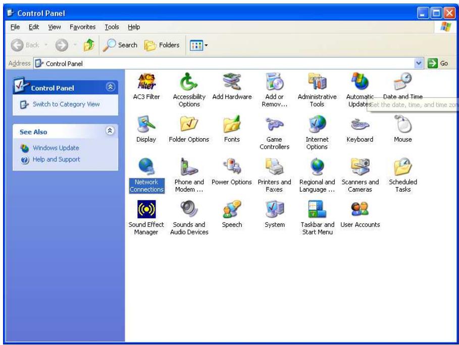
1. Select Start > Settings > Control Panel.
2. Double-click the Network icon.
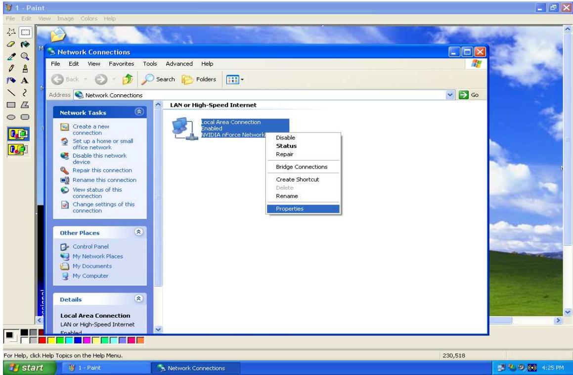
3. In the Network Connections window, right-click Local Area Connection and select Properties.
- Select Internet Protocol (TCP/IP) and click Properties.

- If an IP address, subnet mask and a Default gateway are shown, write down the information. If no address is present, your account's IP address is dynamically assigned. Click the Obtain an IP address automatically radio button.
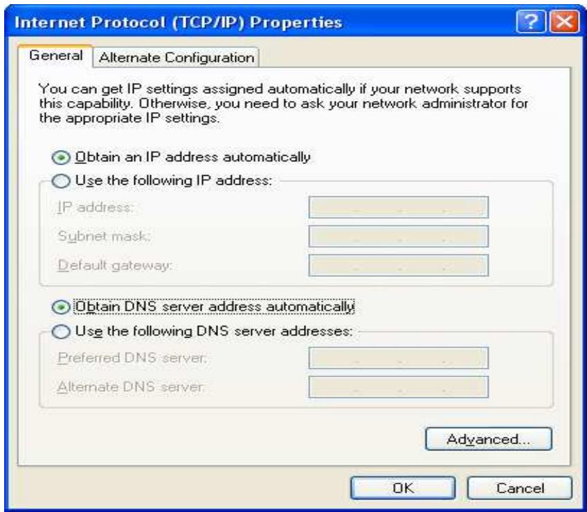
- If any DNS server addresses are shown, write them down. Click the Obtain DNS server address automatically radio button.
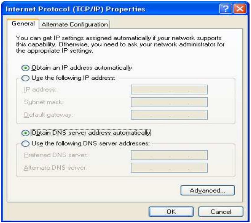
- Click OK to save your changes.
3.7 Web Configuration Interface
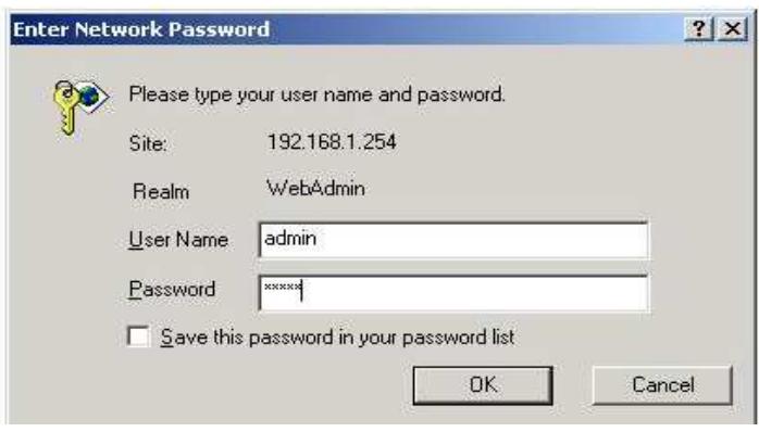
The RF30 includes a Web Configuration Interface for easy administration via virtually any browser on your network. To access this interface, open your web browser, enter the IP address of your router, which by default is 192.168.1.254, and click Go. A user name and password window prompt will appear. Enter your user name and password (the default user name and password are "admin" and "admin") to access the Web Configuration Interface.

If the Web Configuration Interface appears, congratulations! You are now ready to configure your RF30. If you are having trouble accessing the interface, please refer to Chapter 5: Troubleshooting for possible resolutions.
Chapter 4: Router Configuration
4.1 Overview
The Web Configuration Interface makes it easy for you to manage your network via any PC connected to it. On the Web Configuration homepage, you will see the navigation pane located on the left hand side. From it, you will be able to select various options used to configure your router.
- Click Apply if you would like to apply the settings on the current screen to the device. The settings will be effective immediately, however the configuration is not saved yet and the settings will be erased if you power off or restart the device.
- Click SAVE CONFIG to save the current settings permanently to the device.
-
Click RESTART to restart the device. There are two options to restart the device. - Select Current Settings if would like to restart using the current configuration. - Select Factory Default Settings if you would like to restart using the factory default configuration.
-
To exit the router's web interface, click LOGOUT. Please ensure that you have saved your configuration settings before you logout. Be aware that the router is restricted to only one PC accessing the web configuration interface at a time. Once a PC has logged into the web interface, other PCs cannot gain access until the current PC has logged out. If the previous PC forgets to logout, the second PC can access the page after a user-defined period (5 minutes by default).
The following sections will show you how to configure your router using the Web Configuration Interface.
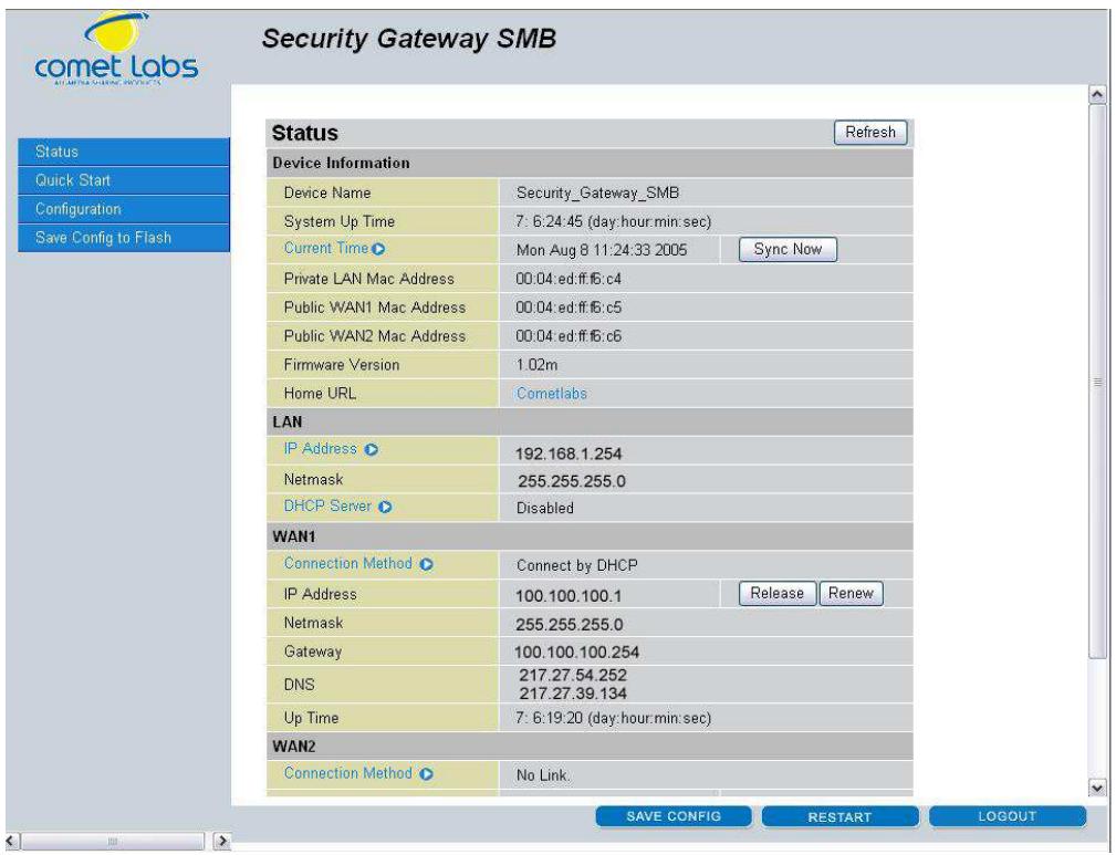
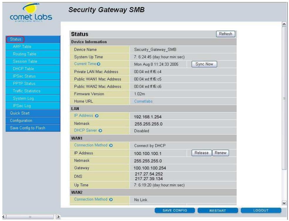
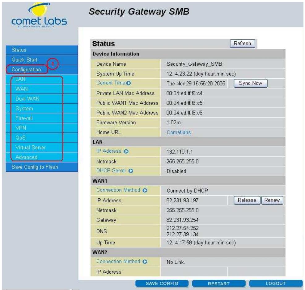
4.2 Status
The Status menu displays the various options that have been selected and a number of statistics about your RF30. In this menu, you will find the following sections:
- ARP Table
- Routing Table
- DHCP Table
- IPSec Status
- Traffic Statistics
- System Log
IPSec Log
4.2.1 ARP Table
The Address Resolution Protocol (ARP) Table shows the mapping of Internet (IP) addresses to Ethernet (MAC) addresses. This is a quick way to determine the MAC address of your PC's network interface to use with the router's Firewall - MAC Address Filter function. See the Firewall section of this chapter for more information on this feature.
Security Gateway SMB
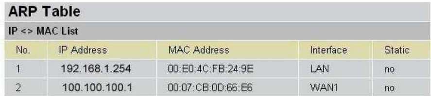
IP Address: A list of IP addresses of devices on your LAN.
MAC Address: The Media Access Control (MAC) addresses for each device on your LAN.
Interface: The interface name (on the router) that this IP address connects to.
Static: Static status of the ARP table entry.
NO indicates dynamically-generated ARP table entries.
YES indicates static ARP table entries added by the user.
4.2.2 Routing Table
The Routing Table displays the current path for transmitted packets. Both static and dynamic routes are displayed.
Security Gateway SMB
| Routing Table | ||||
| Routing Table | ||||
| No. | Destination | Netmask | Gateway/Interface | Cost |
| 1 | 192.168.1.0 | 255.255.255.0 | 0.0.0.0/ LAN | 0 |
| 2 | 100.100.100.0 | 255.255.255.0 | 0.0.0.0/ WAN1 | 0 |
| 3 | 0.0.0.0 | 0.0.0.0 | 100.100.100.254 / WAN1 | 0 |
Destination: The IP address of the destination network.
Netmask: The destination netmask address.
Gateway/Interface: The IP address of the gateway or existing interface that this route will use.
Cost: The number of hops counted as the cost of the route.
4.2.3 DHCP Table
The DHCP Table displays a list of IP addresses that have been assigned to PCs on your network via Dynamic Host Configuration Protocol (DHCP).
Security Gateway SMB
| DHCP Table | ||||
| DHCP IP Assignment Table | ||||
| No. | IP Address | Device Name | MAC Address | Lease Time |
| Refresh | ||||
IP Address: A list of IP addresses of devices on your LAN.
Device Name: The host name (computer name) of the client.
MAC Address: The MAC address of client.
4.2.4 IPSec Status
The IPSec Status window displays the status of the IPSec Tunnels that are currently configured on your RF30.
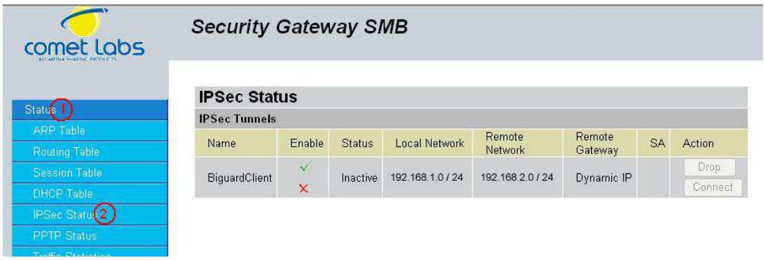
Name: The name you assigned to the particular IPSec entry.
Active: Whether the IPSec connection is currently active.
Connection State: Whether the IPSec is connected or disconnected.
Local Subnet: The local IP address or subnet used.
Remote Subnet: The subnet of the remote site.
Remote Gateway: The remote gateway IP address.
SA: The Security Association for this IPSec entry.
Action: Manually connect or drop the tunnel.
4.2.5 PPTP Status
The PPTP Status window displays the status of the PPTP Tunnels that are currently configured on your RF 30.
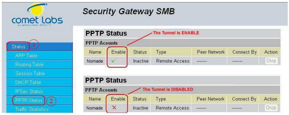
Name: The name you assigned to the particular PPTP entry.
Enable: Whether the PPTP connection is currently Enable or Disable.
Status: Whether the PPTP is Active, Inactive or Disable.
Type: Whether the Connection type is Remote Access or LAN to LAN
Peer Network: The Remote subnet for LAN to LAN as connection type.
Connect by: The remote address when connected.
Action: Manually drop the tunnel.
4.2.6 Traffic Statistics
The Traffic Statistics window displays both sent and received sent data (in Bytes/sec) over a one hour duration. The line in red represents WAN1, while the line in blue represents WAN2.
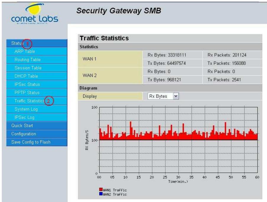
WAN1: Transmitted (Tx) and Received (Rx) bytes and packets for WAN1.
WAN2: Transmitted (Tx) and Received (Rx) bytes and packets for WAN2.
Display: Allows you to change the units of measurement for the traffic graph.
4.2.7 System Log
This window displays the RF30's System Log entries. Major events are logged on this window.
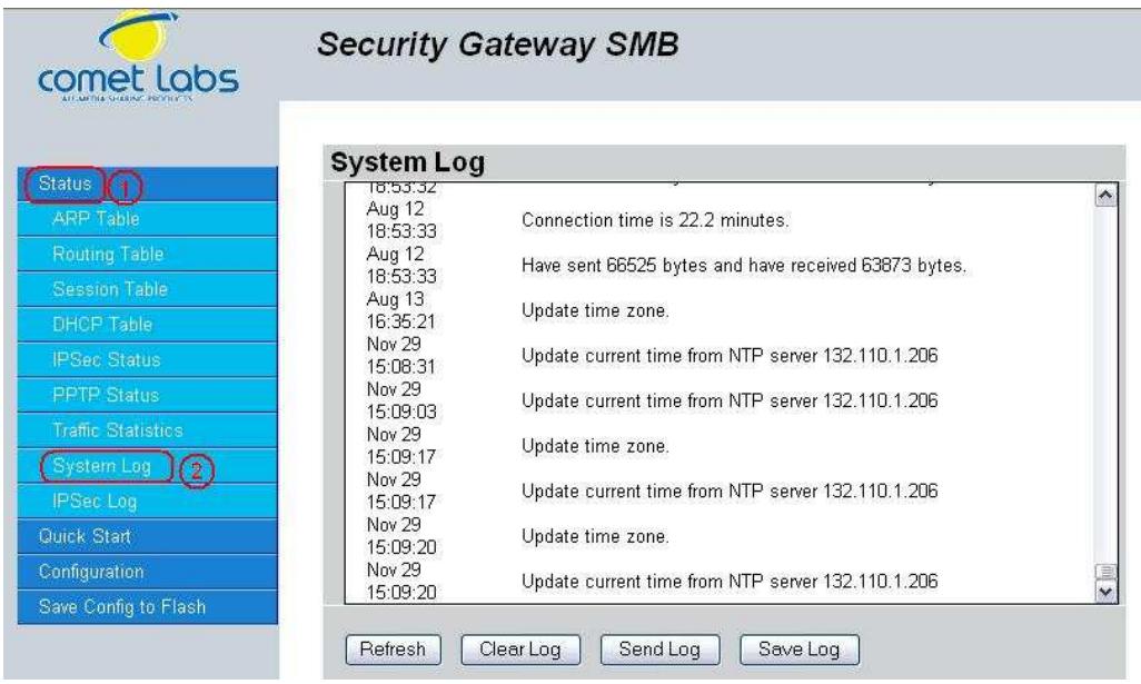
Refresh: Refresh the System Log.
Clear Log: Clear the System Log.
Send Log: Send the System Log to your email account. You can set the email address in Configuration > System > Email Alert. See the Email Alert section for more details.
4.2.8 IPSec Log
This page displays the router's IPSec Log entries. Major events are logged to this window.
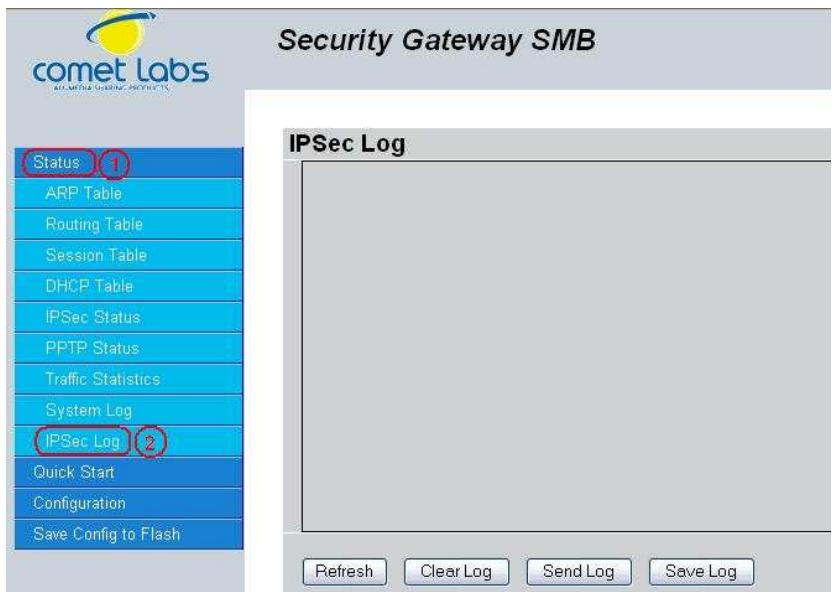
Refresh: Refresh the IPSec Log.
Clear Log: Clear the IPSec Log.
Send Log: Send IPSec Log to your email account. You can set the email address in Configuration > System > Email Alert. See the Email Alert section for more details.
Please refer to Appendix F: IPSec Log Events for more information on log events.
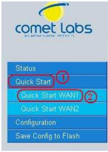
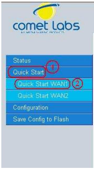
4.3 Quick Start
The Quick Start menu allows you to quickly configure your network for Internet access using the most basic settings.
Security Gateway SMB
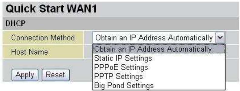
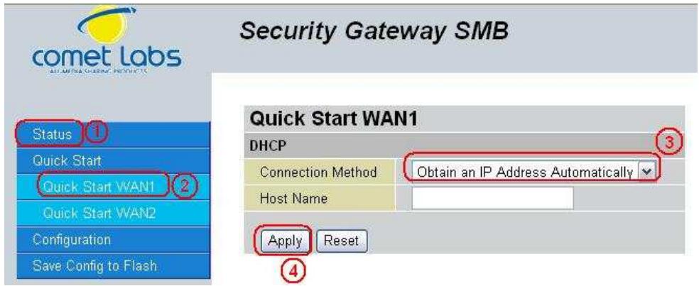
Connection Method: Select your router's connection to the Internet. Selections include Obtain an IP Address Automatically, Static IP Settings, PPPoE Settings, PPTP Settings, and Big Pond Settings.
4.3.1 DCHP
The following is information regarding your ISP that you will need to enter in order to properly configure your Internet connection. If you select to Obtain an IP Address Automatically, these will be automatically set for you, provided that your ISP dynamically assigns an IP address.
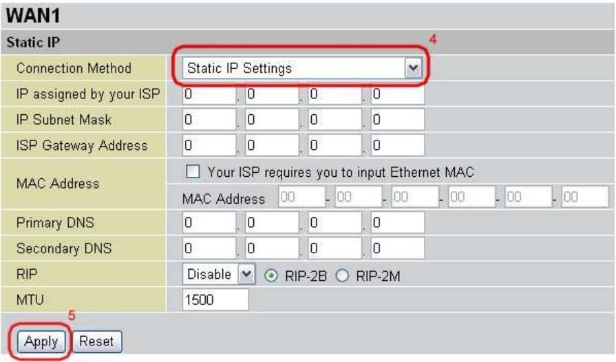
4.3.2 Static IP
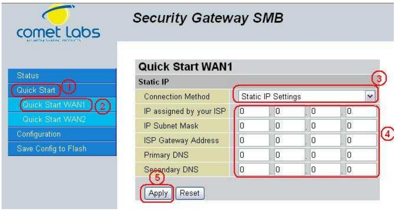
IP assigned by your ISP: Enter the assigned IP address from your IP.
IP Subnet Mask: Enter your IP subnet mask.
ISP Gateway Address: Enter your ISP gateway address.
Primary DNS: Enter your primary DNS.
Secondary DNS: Enter your secondary DNS.
Click Apply to save your changes. To reset to defaults, click Reset.
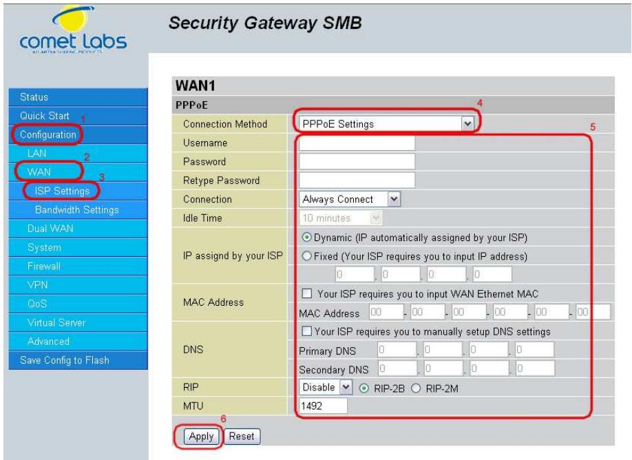
4.3.3 PPPoE
Security Gateway SMB
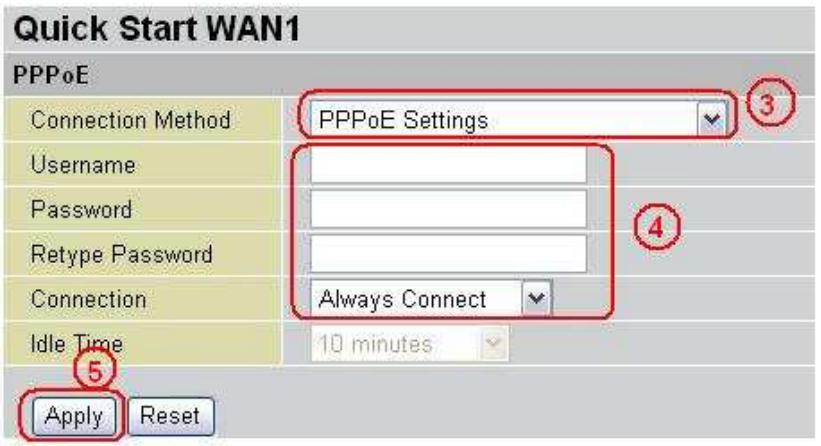
Username: Enter your user name.
Password: Enter your password.
Retype Password: Retype your password.
Connection: Select whether the connection should Always Connect or Trigger on Demand. If you want the router to establish a PPPoE session when starting up and to automatically re-establish the PPPoE session when disconnected by the ISP, select Always Connect. If you want to establish a PPPoE session only when there is a packet requesting access to the Internet (i.e. when a program on your computer attempts to access the Internet), select Trigger on Demand.
Idle Time: Auto-disconnect the router when there is no activity on the line for a predetermined period of time. Select the idle time from the drop down menu. Active if Trigger on Demand is selected.
Click Apply to save your changes. To reset to defaults, click Reset.
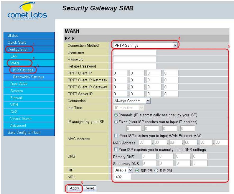
4.3.4 PPTP
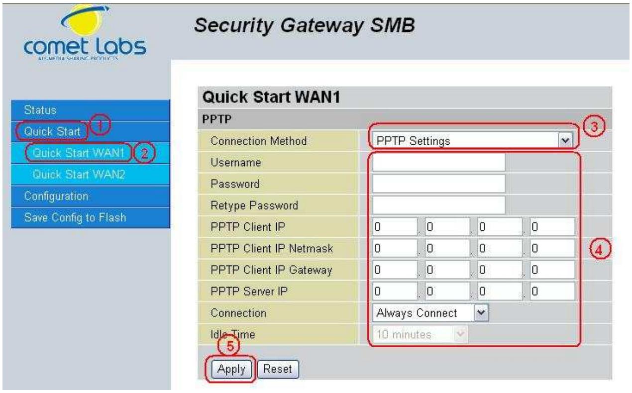
Username: Enter your user name.
Password: Enter your password.
Retype Password: Retype your password.
PPTP Client IP: Enter the PPTP Client IP provided by your ISP.
PPTP Client IP Netmask: Enter the PPTP Client IP Netmask provided by your ISP.
PPTP Client IP Gateway: Enter the PPTP Client IP Gateway provided by your ISP.
PPTP Server IP: Enter the PPTP Server IP provided by your ISP.
Connection: Select whether the connection should Always Connect or Trigger on Demand. If you want the router to establish a PPTP session when starting up and to automatically re-establish the PPTP session when disconnected by the ISP, select Always Connect. If you want to establish a PPTP session only when there is a packet requesting access to the Internet (i.e. when a program on your computer attempts to access the Internet), select Trigger on Demand.
Idle Time: Auto-disconnect the router when there is no activity on the line for a predetermined period of time. Select the idle time from the drop down menu. Active if Trigger on Demand is selected.
Click Apply to save your changes. To reset to defaults, click Reset.
4.3.5 Big Pond
Username: Enter your user name.
Password: Enter your password.
Retype Password: Retype your password.
Login Server: Enter the IP of the Login server provided by your ISP.
Click Apply to save your changes. To reset to defaults, click Reset.
For detailed instructions on configuring WAN settings, please refer to the WAN section of this chapter.
4.4 Configuration
The Configuration menu allows you to set many of the operating parameters of the RF30. In this menu, you will find the following sections:
- LAN
-WAN - Dual WAN
- System
- Firewall
- IPSec
- QoS
- Virtual Server
- Advanced
These items are described below in the following sections.
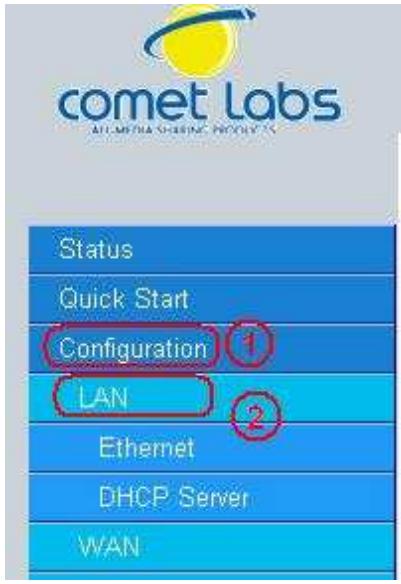
4.4.1 LAN
There are two items within this section: Ethernet and DHCP Server.
Security Gateway SMB
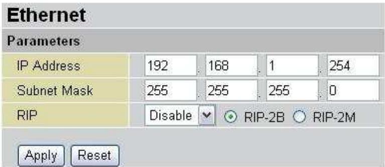
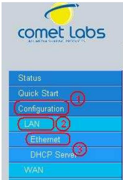
4.4.1.1 Ethernet
Security Gateway SMB
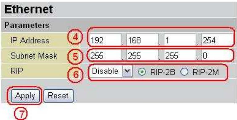
IP Address: Enter the internal LAN IP address for the RF30 (192.168.1.254 by default).
Subnet Mask: Enter the subnet mask (255.255.255.0 by default).
RIP: RIP v2 Broadcast and RIP v2 Multicast. Check to enable RIP.
4.4.1.2 DHCP Server
In this menu, you can disable or enable the Dynamic Host Configuration Protocol (DHCP) server. The DHCP protocol allows your RF30 to dynamically assign IP addresses to PCs on your network if they are configured to automatically obtain IP addresses.
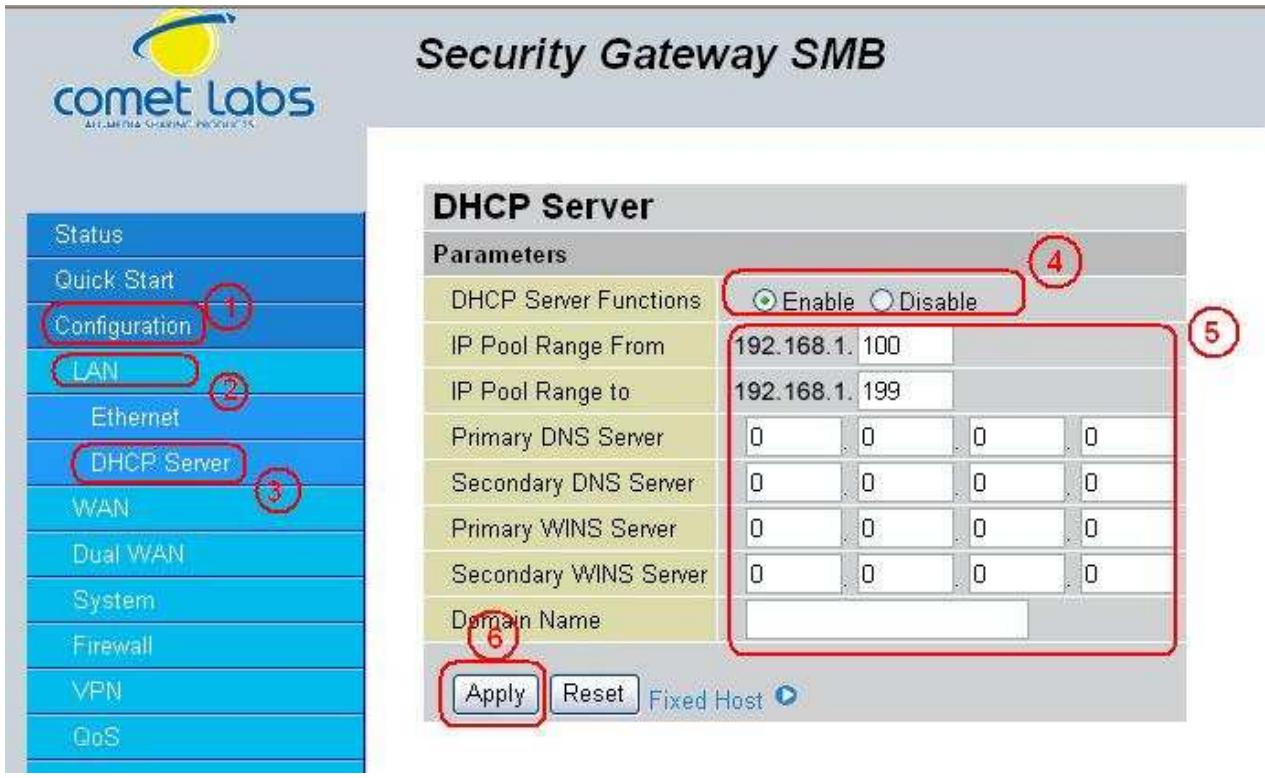
To disable the router's DHCP Server, select the Disable radio button, and then click Apply. When the DHCP Server is disabled, you will need to manually assign a fixed IP address to each PC on your network, and set the default gateway for each PC to the IP address of the router (192.168.1.254 by default).
To configure the router's DHCP Server, select the Enable radio button, and then configure parameters of the DHCP Server including the IP Pool (starting IP address and ending IP address to be allocated to the PCs on your network), DNS Server, WINS Server, and Domain Name. These details are sent to each DHCP client when they request an IP address from the DHCP server. Click Apply to enable this function.
Fixed Host allows specific computer/network clients to have a reserved IP address.
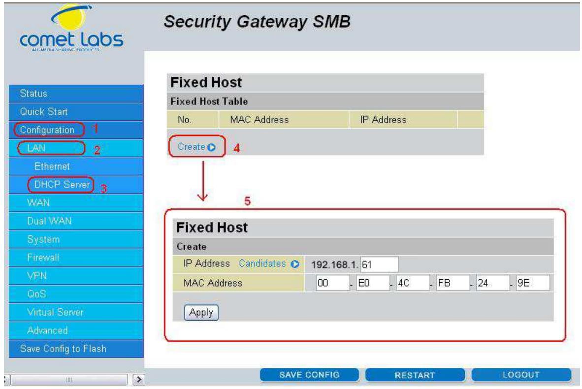
IP Address: Enter the IP address that you want to reserve for the above MAC address. MAC Address: Enter the MAC address of the PC or server you wish to be assigned a reserved IP.
Click the Apply button to add the configuration into the Host Table. Press the Delete button to delete a configuration from the Host Table.
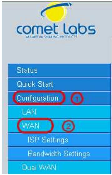
4.4.2 WAN
WAN refers to your Wide Area Network connection. In most cases, this means your router's connection to the Internet through your ISP. The RF30 features Dual WAN capability.
Security Gateway SMB
| ISP Settings | ||
| WAN Service Table | ||
| Name | Description | |
| WAN1 | DHCP | Edit |
| WAN2 | DHCP | Edit |
The WAN menu contains two items: ISP Settings and Bandwidth Settings.
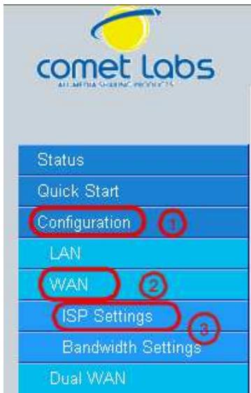
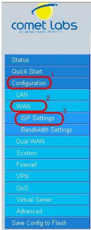
4.4.2.1 ISP Settings
Security Gateway SMB
| ISP Settings | ||
| WAN Service Table | ||
| Name | Description | |
| WAN1 | DHCP | Edit |
| WAN2 | DHCP | Edit |
This WAN Service Table displays the different WAN connections that are configured on the RF30.
To edit any of these connections, click Edit. You will be taken to the following menu.
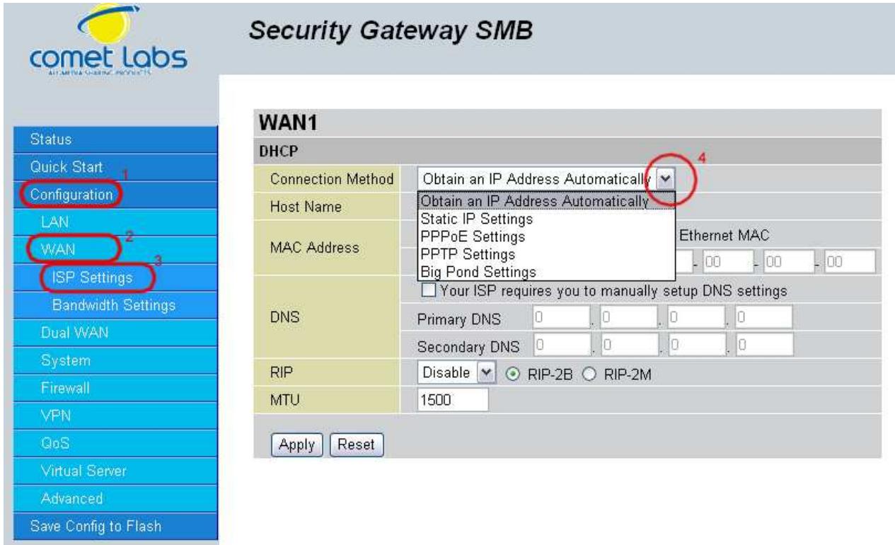
Connection Method: Select how your router will connect to the Internet. Selections include Obtain an IP Address Automatically, Static IP Settings, PPPoE Settings, PPTP Settings, and Big Pond Settings. For each WAN port, the factory default is DHCP. If your ISP does not use DHCP, select the correct connection method and configure the connection accordingly. Configurable items will vary depending on the connection method selected.
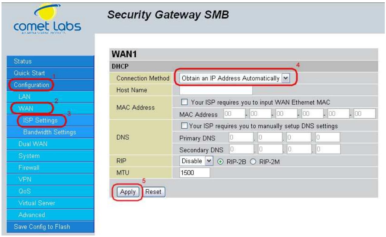
Host Name: Some ISPs authenticate logins using this field.
MAC Address: If your ISP requires you to input a WAN Ethernet MAC, check the checkbox and enter your MAC address in the blanks below.
DNS: If your ISP requires you to manually setup DNS settings, check the checkbox and enter your primary and secondary DNS.
RIP: To activate RIP, select Send, Receive, or Both from the drop down menu. To disable RIP, select Disable from the drop down menu.
MTU: Enter the Maximum Transmission Unit (MTU) for your network.
Click Apply to save your changes. To reset to defaults, click Reset.
Security Gateway SMB
IP assigned by your ISP: Enter the static IP assigned by your ISP.
IP Subnet Mask: Enter the IP subnet mask provided by your ISP.
ISP Gateway Address: Enter the ISP gateway address provided by your ISP.
MAC Address: If your ISP requires you to input a WAN Ethernet MAC, check the checkbox and enter your MAC address in the blanks below.
Primary DNS: Enter the primary DNS provided by your ISP.
Secondary DNS: Enter the secondary DNS provided by your ISP.
RIP: To activate RIP, select Send, Receive, or Both from the drop down menu. To disable RIP, select Disable from the drop down menu.
MTU: Enter the Maximum Transmission Unit (MTU) for your network.
Click Apply to save your changes. To reset to defaults, click Reset.
4.4.2.1.3 PPPoE
Username: Enter your user name.
Password: Enter your password.
Retype Password: Retype your password.
Connection: Select whether the connection should Always Connect or Trigger on Demand. If you want the router to establish a PPPoE session when starting up and to automatically re-establish the PPPoE session when disconnected by the ISP, select Always Connect. If you want to establish a PPPoE session only when there is a packet requesting access to the Internet (i.e. when a program on your computer attempts to access the Internet), select Trigger on Demand.
Idle Time: Auto-disconnect the router when there is no activity on the line for a predetermined period of time. Select the idle time from the drop down menu. Active if Trigger on Demand is selected.
IP Assigned by your ISP: If your IP is dynamically assigned by your ISP, select the Dynamic radio button. If your IP assigns a static IP address, select the Static radio button, and input your IP address in the blank provided.
MAC Address: If your ISP requires you to input a WAN Ethernet MAC, check the checkbox and enter your MAC address in the blanks below.
DNS: If your ISP requires you to manually setup DNS settings, check the checkbox and enter your primary and secondary DNS.
RIP: To activate RIP, select Send, Receive, or Both from the drop down menu. To disable RIP, select Disable from the drop down menu.
MTU: Enter the Maximum Transmission Unit (MTU) for your network.
Click Apply to save your changes. To reset to defaults, click Reset.
4.4.2.1.4 PPTP Settings
Username: Enter your user name.
Password: Enter your password.
Retype Password: Retype your password.
PPTP Client IP: Enter the PPTP Client IP provided by your ISP.
PPTP Client IP Netmask: Enter the PPTP Client IP Netmask provided by your ISP.
PPTP Client IP Gateway: Enter the PPTP Client IP Gateway provided by your ISP.
PPTP Server IP: Enter the PPTP Server IP provided by your ISP.
Connection: Select whether the connection should Always Connect or Trigger on Demand. If you want the router to establish a PPTP session when starting up and to automatically re-establish the PPTP session when disconnected by the ISP, select Always Connect. If you want to establish a PPTP session only when there is a packet requesting access to the Internet (i.e. when a program on your computer attempts to access the Internet), select Trigger on Demand.
Idle Time: Auto-disconnect the router when there is no activity on the line for a predetermined period of time. Select the idle time from the drop down menu. Active if Trigger on Demand is selected.
IP Assigned by your ISP: If your IP is dynamically assigned by your ISP, select the Dynamic radio button. If your IP assigns a static IP address, select the Static radio button. This will take you to another page for inputting the IP address information.
MAC Address: If your ISP requires you to input a WAN Ethernet MAC, check the checkbox and enter your MAC address in the blanks below.
DNS: If your ISP requires you to manually setup DNS settings, check the checkbox and enter your primary and secondary DNS.
RIP: To activate RIP, select Send, Receive, or Both from the drop down menu. To disable RIP, select Disable from the drop down menu.
MTU: Enter the Maximum Transmission Unit (MTU) for your network.
Click Apply to save your changes. To reset to defaults, click Reset.
4.4.2.1.5 Big Pond Settings
Username: Enter your user name.
Password: Enter your password.
RETYPE Password: RETYPE your password.
Login Server: Enter the IP of the Login server provided by your ISP.
MAC Address: If your ISP requires you to input a WAN Ethernet MAC, check the checkbox and enter your MAC address in the blanks below.
DNS: If your ISP requires you to manually setup DNS settings, check the checkbox and enter your primary and secondary DNS.
RIP: To activate RIP, select Send, Receive, or Both from the drop down menu. To disable RIP, select Disable from the drop down menu.
MTU: Enter the Maximum Transmission Unit (MTU) for your network.
Click Apply to save your changes. To reset to defaults, click Reset.
A simpler alternative is to select Quick Start from the main menu. Please see the Quick Start section of this chapter for more information.
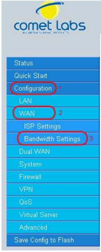
4.4.2.2 Bandwidth Settings
Under Bandwidth Settings, you can easily configure both inbound and outbound bandwidth for each WAN port.
Security Gateway SMB

WAN1: Enter your ISP inbound and outbound bandwidth for WAN1.
WAN2: Enter your ISP inbound and outbound bandwidth for WAN2.
NOTE: These values entered here are referenced by both QoS and Load Balancing functions.
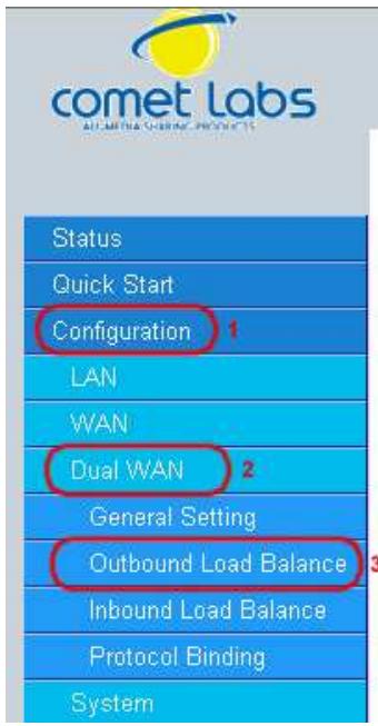
4.4.3 Dual WAN
In this section, you can setup the fail over or load balance function, outbound load balance or inbound load balance function, or setup specific protocol to bind with specific WAN port. In this menu are the following sections: General Settings, Outbound Load Balance, Inbound Load Balance, and Protocol Binding.
4.4.3.1 General Settings

Mode: You can select Load Balance or Fail Over.
Service Detection: Enables or disables the service detection feature. For fail over, the service detection function is enabled. For load balance, user is able to enable or disable it.
Connectivity Decision: Establishes the number of times probing the connection has to fail before the connection is judged as failed.
Probe Cycle: The number of seconds between each probe.
Probe WAN1: Determines if WAN1 is a gateway or host. If host is selected, please enter the IP address.
Probe WAN2: Determines if WAN2 is a gateway or host. If host is selected, please enter the IP address.
Feedback to WAN1 when possible: Enables or disables feedback to WAN1. This function only applies to fail over.
Click Apply to save your changes.
4.4.3.2 Outbound Load Balance
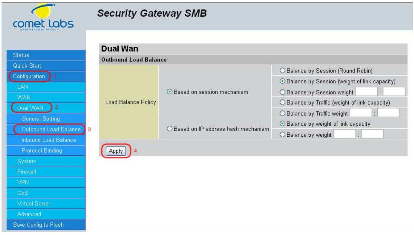
Outbound Load Balancing on the RF30 can be based on one of two methods:
- By session mechanism
- By IP address hash mechanism
Choose one by clicking the corresponding radio button.
Based on Session Mechanism: The source IP address and destination IP address might go through WAN1 or WAN2 according to policy settings in this mechanism. You can choose this mechanism if the applications the users use will not tell the difference of the WAN IP addresses. (some applications in the Internet need to identify the source IP address, e.g. Back, Forum, ...)
Balance by Session (Round Robin): Balances session traffic based on a round robin method.
Balance by Session (weight of length capacity): Balances session traffic based on weight of length capacity.
Balance by Session weight: Balances session traffic based on a weight ratio. Enter the desired ratio in the blanks provided.
Balance by Traffic (weight of length capacity): Balances traffic based on weight of link capacity.
Balance by Traffic weight: Balances traffic based on a traffic weight ratio. Enter the desired ratio into the blanks provided.
Based on IP hash mechanism: The source IP address and destination IP address will go through specific WAN port (WAN1 or WAN2) according to policy settings in this mechanism. This will assure that some applications will work when it would like to authenticate the source IP address.
Balance by weight of link capacity: Uses an IP hash to balance traffic based on weight of link bandwidth capacity.
Balance by weight: Uses an IP hash to balance traffic based on a ratio. Enter the desired ratio into the blanks provided.
Click Apply to save your changes.
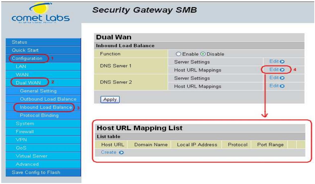
4.4.3.3 Inbound Load Balance
Security Gateway SMB
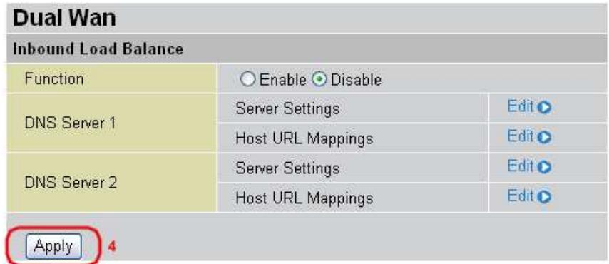
Function: Used to enable or disable inbound load balancing.
DNS Server 1: DNS Server 1 settings including Host URL mappings.
DNS Server 2: DNS Server 2 settings including Host URL mappings.
To edit server settings, click Edit. The following example illustrates DNS Server 1 settings. DNS Server 2 settings follow a similar procedure.
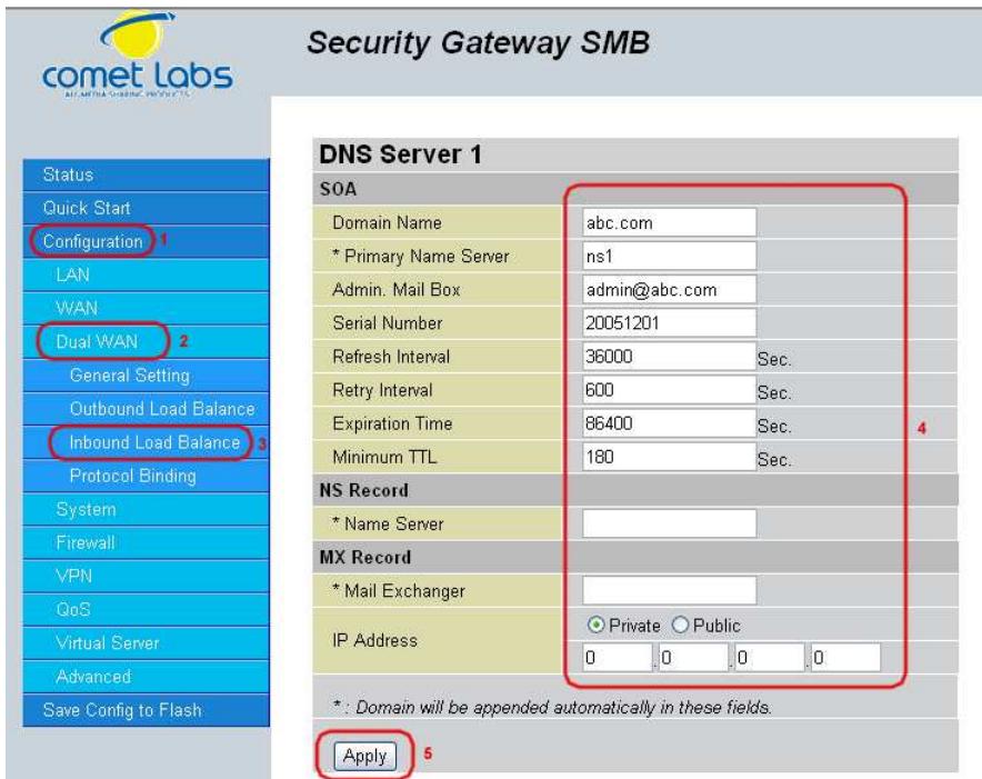
SOA:
Domain Name: The domain name of DNS Server 1. It is the name that you register on DNS organization. You have to fill-out the Fully Qualified Domain Name (FQDN) with an ending character (a dot) for this text field.(ex:abc.com.). When you enter the following domain name, you can only input different chars without an ending dot, its name is then added with domain name, and it becomes FQDN.
Primary Name Server: The name assigned to the Primary Name Server. (e.g:aaa, its FQDN is aaa.abc.com.)
Admin. Mail Box: The administrator's email account.(e.g:admin@abc.com.)
Serial Number: It is the version number that keeps in the SOA record.
Refresh Interval: The interval refreshes are done. Denoted in seconds.
Retry Interval: The interval retries are done. Denoted in seconds.
Expiration Time: The length of time that can elapse before the zone is no longer authoritative. Denoted in seconds.
Minimum TTL: The minimum time to live. Denoted in seconds.
NS Record
Name Server: The name of the Primary Name Server.
MX Record
Mail Exchanger: The name of the mail server.
IP Address: The mail server IP address.
Click Apply to save your changes.
To edit the Host Mapping URL list, click Edit. This will open the Host Mapping URL table, which lists the current Host Mapping URLs.
To add a host mapping URL to the list, click Create.
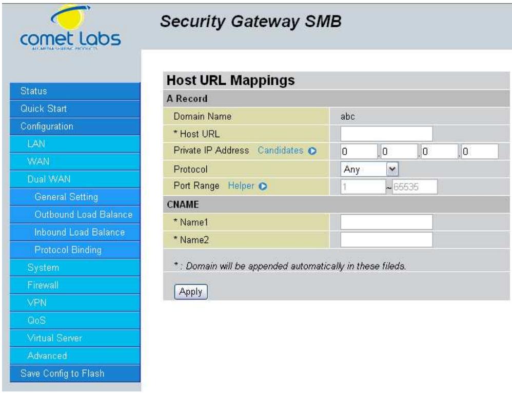
Domain Name: The domain name of the local host.
Host URL: The URL to be mapped.
Private IP Address: The IP address of the local host.
Port Range: The port range of all incoming packets are accepted and processed by a local host with the specified private IP address.
Name1: The Alias Host URL
Name2: The Alias Host URL
Click Apply to save your changes.
4.4.3.4 Protocol Binding
Protocol Binding lets you direct specific traffic to go out from a specific WAN port. Click the Create button to create a new policy entry. Policies entered would tell specific types of Internet traffic from a particular range of IPs to go to a particular range of IPs with ONE WAN port, rather than using both of the WAN ports with load balancing.
(NOTE: If any policies are added in the Protocol Binding section, please note that it would take precedence over the settings that are already configured in the Load Balance Setting section.)

The Protocol Binding Table lists any protocol binding that has been configured. To add a new binding, click Create.
Interface: Choose which WAN port to use: WAN1, WAN2
Packet Type: The particular protocol of Internet traffic for the specified policy.
Choose from TCP, UDP, or Any.
Source IP Range:
All Source IP: Click it to specify all source IPs.
Specified Source IP: Click to specify a specific source IP address and source IP netmask.
Source IP Address: If Specified Source IP was chosen, here's where the IP can be entered.
Source IP Netmask: If Specified Source IP was chosen, here's where the subnet mask can be entered.
Destination IP Range:
All Destination IP: Click it to specific all source IP.
- Specified Destination IP: Click to specify a specific destination IP address and Destination IP Netmask.
Destination IP Address: If Specified Destination IP was chosen, here's where the IP can be entered.
Destination IP Netmask: If Specified Destination IP was chosen, here's where the subnet mask can be entered.
Port Range: The range of ports for the specified policy (if you only want to use one port, enter the same value in both boxes).
Click Apply to save your changes.
4.4.4 System
The System menu allows you to adjust a variety of basic router settings, upgrade firmware, set up remote access, and more. In this menu are the following sections: Time Zone, Remote Access, Firmware Upgrade, Backup/Restore, Restart, Password, System Log and Email Alert.
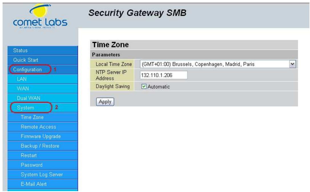
4.4.4.1 Time Zone
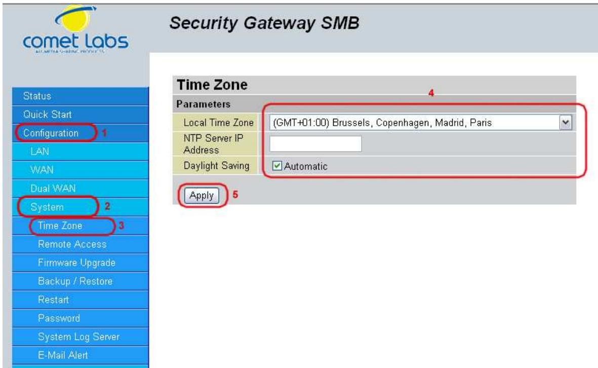
The RF30 does not use an onboard real time clock; instead, it uses the Network Time Protocol (NTP) to acquire the current time from an NTP server outside your network. Simply choose your local time zone, enter NTP Server IP Address, and click Apply. After connecting to the Internet, the RF30 will retrieve the correct local time from the NTP server you have specified. Your ISP may provide an NTP server for you to use.
To have the RF30 automatically adjust for Daylight Savings Time, check the Automatic checkbox.
4.4.4.2 Remote Access
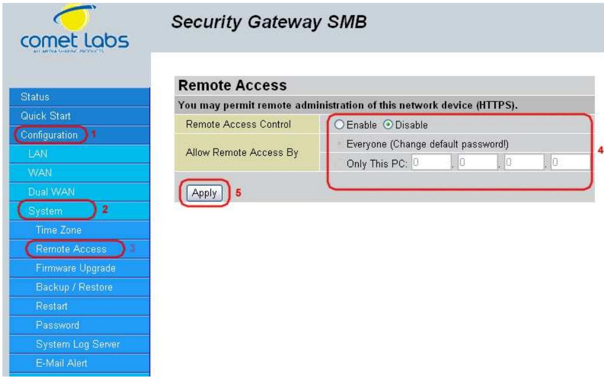
To allow remote users to configure and manage the RF30 through the Internet, select the Enable radio button. To deactivate remote access, select the Disable radio button. This function also enables you grant access from any PC or from a specific IP address. Click Apply to save your settings.
NOTE: When enabling remote access, be sure to change the default administration password to something more secure.
4.4.4.3 Firmware Upgrade
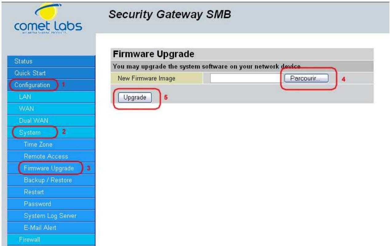
Upgrading your RF30's firmware is a quick and easy way to enjoy increased functionality, better reliability, and ensure trouble-free operation. To upgrade your firmware, simply visit Cometlabs's website (http://www.Cometlabs.com) and download the latest firmware image file for the RF30. Next, click Browse and select the newly downloaded firmware file. Click Upgrade to complete the update.
NOTE: DO NOT power down the router or interrupt the firmware upgrade while it is still in process. Interrupting the firmware upgrade process could damage the router.
4.4.4.4 Backup / Restore
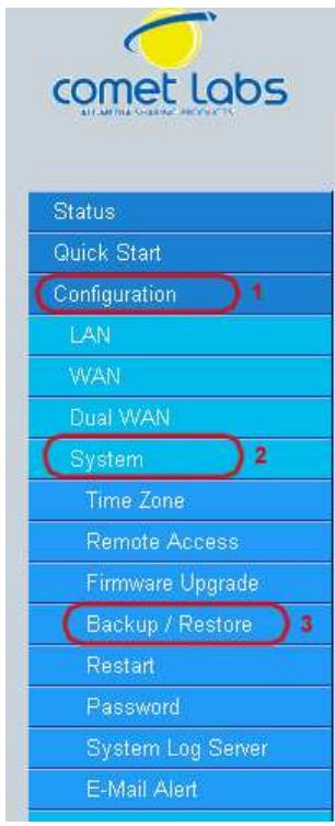
Security Gateway SMB
Backup/Restore
Allows you to backup the configuration settings to your computer, or restore configuration from your computer.
Backup Configuration
Backup configuration to your computer.
Backup
Restore Configuration
Configuration File
Parcourir...
"Restore" will overwrite the current configuration and restart the device. If you want to keep the current configuration, please use "Backup" first to save current configuration.
Restore
This feature allows you to save and backup your router's current settings, or restore a previously saved backup. This is useful if you wish to experiment with different settings, knowing that you have a backup handy. It is advisable to backup your router's settings before making any significant changes to your router's configuration.
To backup your router's settings, click Backup and select where to save the settings backup file. You may also change the name of the file when saving if you wish to keep multiple backups. Click OK to save the file.
To restore a previously saved backup file, click Browse. You will be prompted to select a file from your PC to restore. Be sure to only restore settings files that have been generated by the Backup function, and that were created when using the same firmware version. Settings files saved to your PC should not be manually edited in any way. After selecting the settings file you wish to use, clicking Restore will load those settings into the router.
4.4.4.5 Restart Router
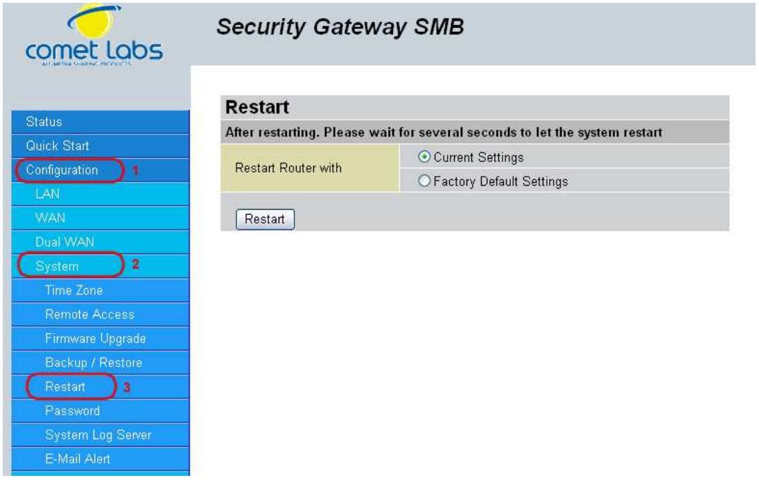
The Restart Router feature allows you to easily restart the RF30. To restart with your last saved configuration, select the Current Settings radio button and click Restart.
If you wish to restart the router using the factory default settings, select Factory Default Settings and click Restart to reboot the RF30 with factory default settings.
You may also reset your router to factory default settings by holding the Reset button on the router until the Status LED begins to blink. Once the RF30 completes the boot sequence, the Status LED will stop blinking.
4.4.4.6 Password
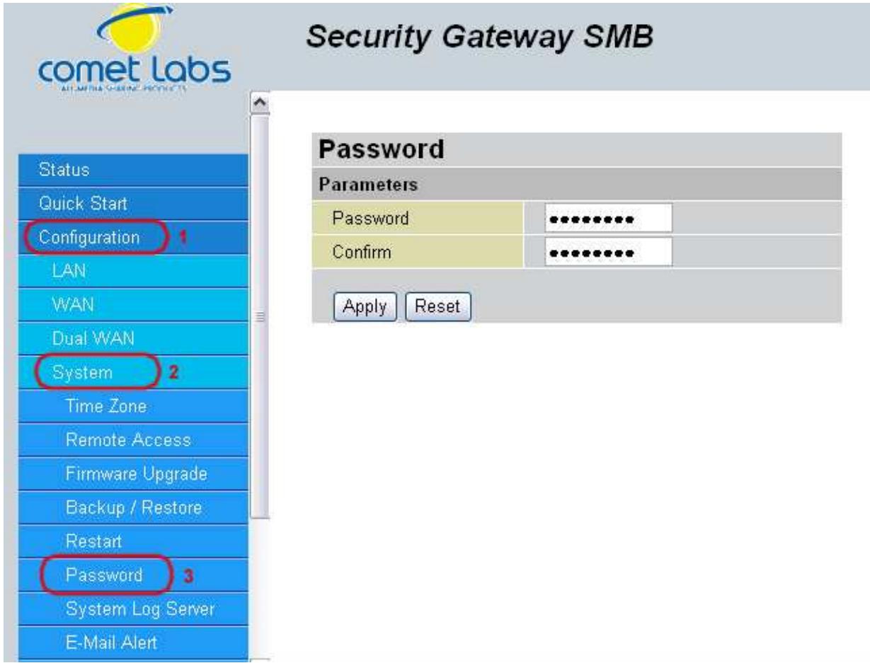
In order to prevent unauthorized access to your router's configuration interface, it requires the administrator to login with a password. You can change your password by entering your new password in both fields. Click Apply to save your changes. Click Reset to reset to the default administration password (admin).
4.4.4.7 System Log Server
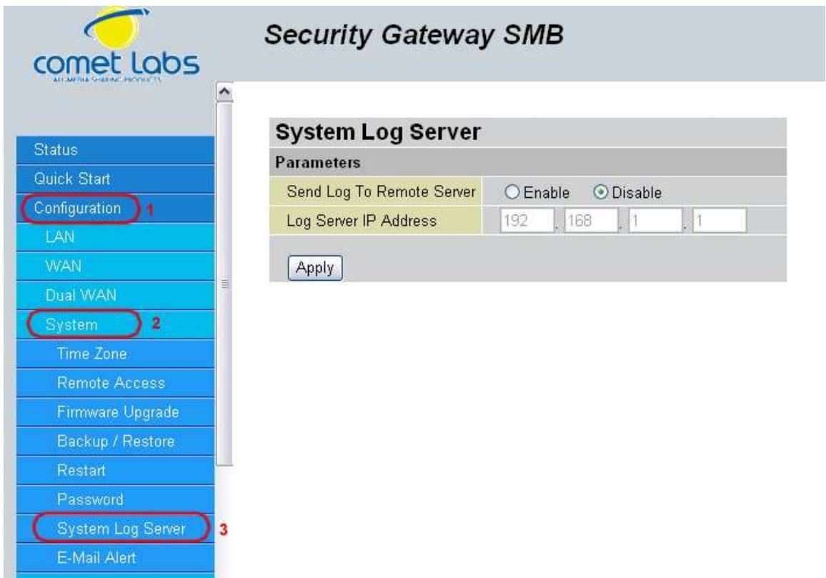
This function allows the RF30 to send system logs to an external Syslog Server. Syslog is an industry-standard protocol used to capture information about network activity. To enable this function, select the Enable radio button and enter your Syslog server IP address in the Log Server IP Address field. Click Apply to save your changes.
To disable this feature, simply select the Disable radio button and click Apply.
4.4.4.8 Email Alert
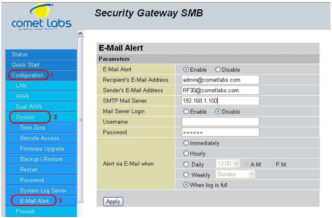
The Email Alert function allows a log of security-related events (such as System Log and IPSec Log) to be sent to a specified email address.
Email Alert: You may enable or disable this function by selecting the appropriate radio button.
Recipient's Email Address: Enter the email address where you wish the alert logs to be sent.
SMTP Mail Server: Enter your email account's outgoing mail server. It may be an IP address or a domain name.
Alert via Email when: Select the frequency of each email update. Choose one of the five options:
Immediately: The router will send an alert immediately.
Hourly: The router will send an alert once every hour.
Daily: The router will send an alert once a day. The exact time can be specified using the pull down menu.
Weekly: The router will send an alert once a week.
When log is full: The router will send an alert only when the log is full.
4.4.5 Firewall
The RF30 includes a full Stateful Packet Inspection (SPI) firewall for controlling Internet access from your LAN, and preventing attacks from hackers. Your router also acts as a "natural"Internetfirewall when using Network Address Translation (NAT), as all PCs on your LAN will use private IP addresses that cannot be directly accessed from the Internet. Please see the WAN configuration section for more details.
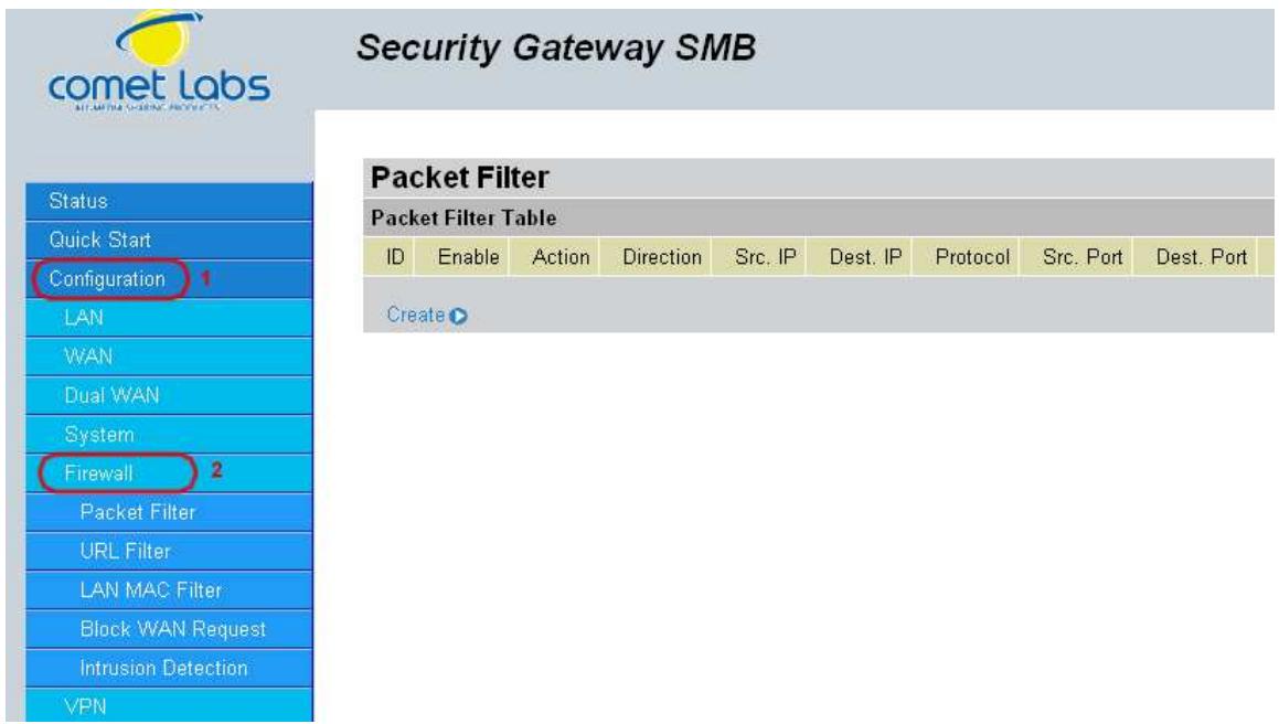
You can find three items under the Firewall section: Packet Filter, URL Filter, and Block WAN Request.
4.4.5.1 Packet Filter
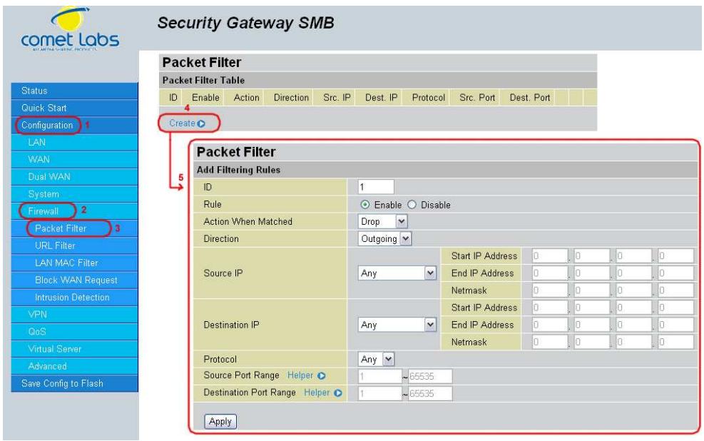
The Packet Filter function is used to limit user access to certain sites on the Internet or LAN. The Filter Table displays all current filter rules. If there is an entry in the Filter Table, you can click Edit to modify the setting of this entry, or click Delete to remove this entry.
To create a new filter rule, click Create.
Direction: Incoming Packet Filter rules prevent unauthorized computers or applications accessing your local network from the Internet. Outgoing Packet Filter rules prevent unauthorized computers or applications accessing the Internet. Select if the new filter rule is incoming or outgoing.
Packet Type: Select the Transport protocol type (Any, TCP, UDP).
Action When Matched: Select to Drop or Forward the packet specified in this filter entry.
Source IP Address: Enter the source IP address this filter rule is to be applied.
Source IP Netmask: Enter the subnet mask of the above IP address.
Destination IP Address: Enter the destination IP address this filter rule is to be applied.
Destination IP Netmask: Enter the subnet mask of the above IP address.
Source Port Range: Enter the source port number range. If you only want to specify one service port, then enter the same port number in both boxes.
Destination Port Range: Enter the destination port number range. If you only want to specify one service port, then enter the same port number in both boxes.
4.4.5.2 URL Filter
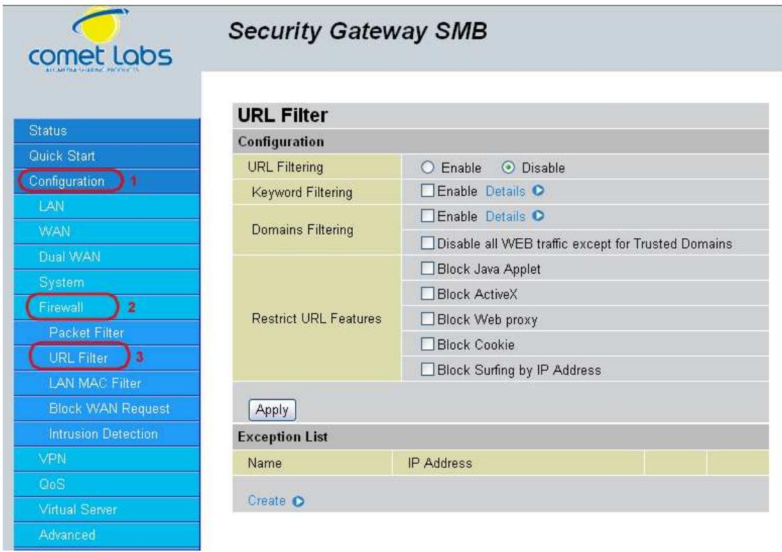
The URL Filter is a powerful tool that can be used to limit access to certain URLs on the Internet. You can block web sites based on keywords or even block out an entire domain. Certain web features can also be blocked to grant added security to your network.
URL Filtering: You can choose to Enable or Disable this feature.
Keyword Filtering: Click the checkbox to enable this feature. To edit the list of filtered keywords, click Details.
Domain Filtering: Click the "enable" checkbox to enable filtering by Domain Name. Click the "Disable all WEB traffic except for trusted domains" check box to allow web access only for trusted domains.
Restrict URL Features: Click "Block Java Applet" to filter web access with Java Applet components. Click "Block ActiveX" to filter web access with ActiveX components. Click "Block Web proxy" to filter web proxy access. Click "Block Cookie" to filter web access with Cookie components. Click "Block Surfing by IP Address" to filter web access with an IP address as the domain name.
Exception List: You can input a list of IP addresses as the exception list for URL filtering.
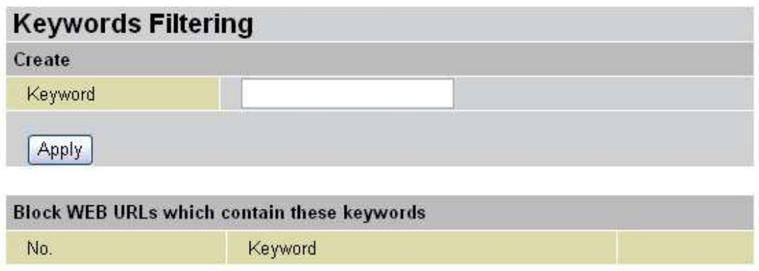
Enter a keyword to be filtered and click Apply. Your new keyword will be added to the filtered keyword listing.
Domains Filtering: Click the top checkbox to enable this feature. You can also choose to disable all web traffic except for trusted sites by clicking the bottom checkbox. To edit the list of filtered domains, click Details.
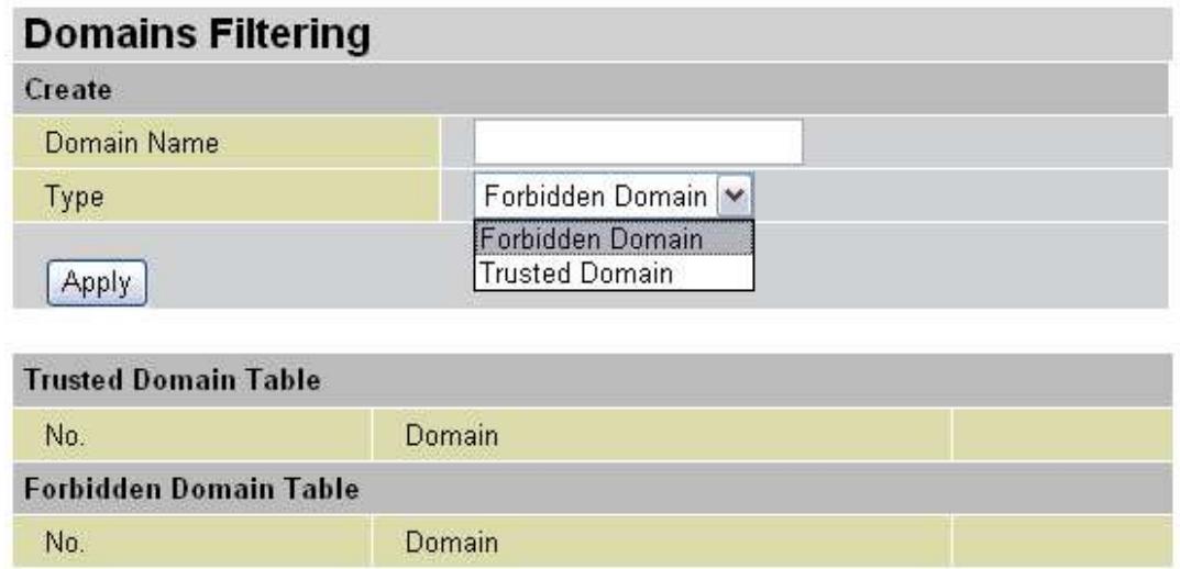
Enter a domain and selected whether this domain is trusted or forbidden with the pulldown menu. Next, click Apply. Your new domain will be added to either the Trusted Domain or Forbidden Domain listing, depending on which you selected previously.
Restrict URL Features: Use this to disable certain web features. Select the options you want (Block Java Applet, Block ActiveX, Block Web proxy, Block Cookie, Block Surfing by IP Address) and click Apply to save your changes.
You may also designate which IP addresses are to be excluded from these filters by adding them to the Exception List. To do so, click Add.
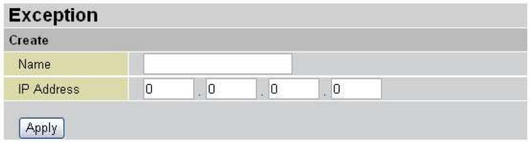
Enter a name for the IP Address and then enter the IP address itself. Click Apply to save your changes. The IP address will be entered into the Exception List, and excluded from the URL filtering rules in effect.
4.4.5.3 LAN MAC Filter
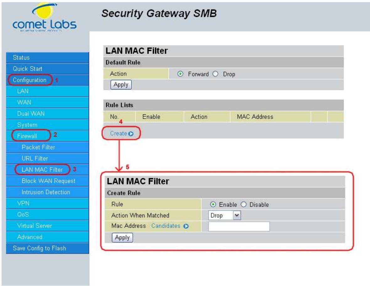
LAN Mac Filter can decide that RF will serve those devices at LAN side or not by MAC Address.
Default Rule: Forward or Drop all LAN request. (Forward by default)
Create: You can also input a specified MAC Address to be dropped or Forward without depending on the default rule.
4.4.5.4 Block WAN Request
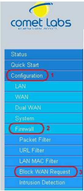
Security Gateway SMB
Block WAN Request
Enable for preventing any ping test from Internet, such as hacker attack.
Block WAN Request
Enable
Disable
Apply
Blocking WAN requests is one way to prevent DDOS attacks by preventing ping requests from the Internet. Use this menu to enable or disable function.
4.4.5.5 Intrusion Detection
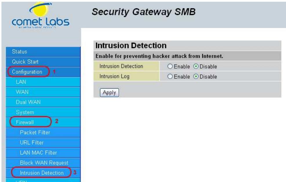
Intrusion Detection can prevent most common DoS attacks from the Internet or from LAN users.
Intrusion Detection: Enable or disable this function.
Intrusion Log: All the detected and dropped attacks will be shown in the system log.
4.4.6 VPN
4.4.6.1 IPSec
IPSec is a set of protocols that enable Virtual Private Networks (VPN). VPN is a way to establish secured communication tunnels to an organization's network via the Internet.
4.4.6.1.1 IPSec Wizard
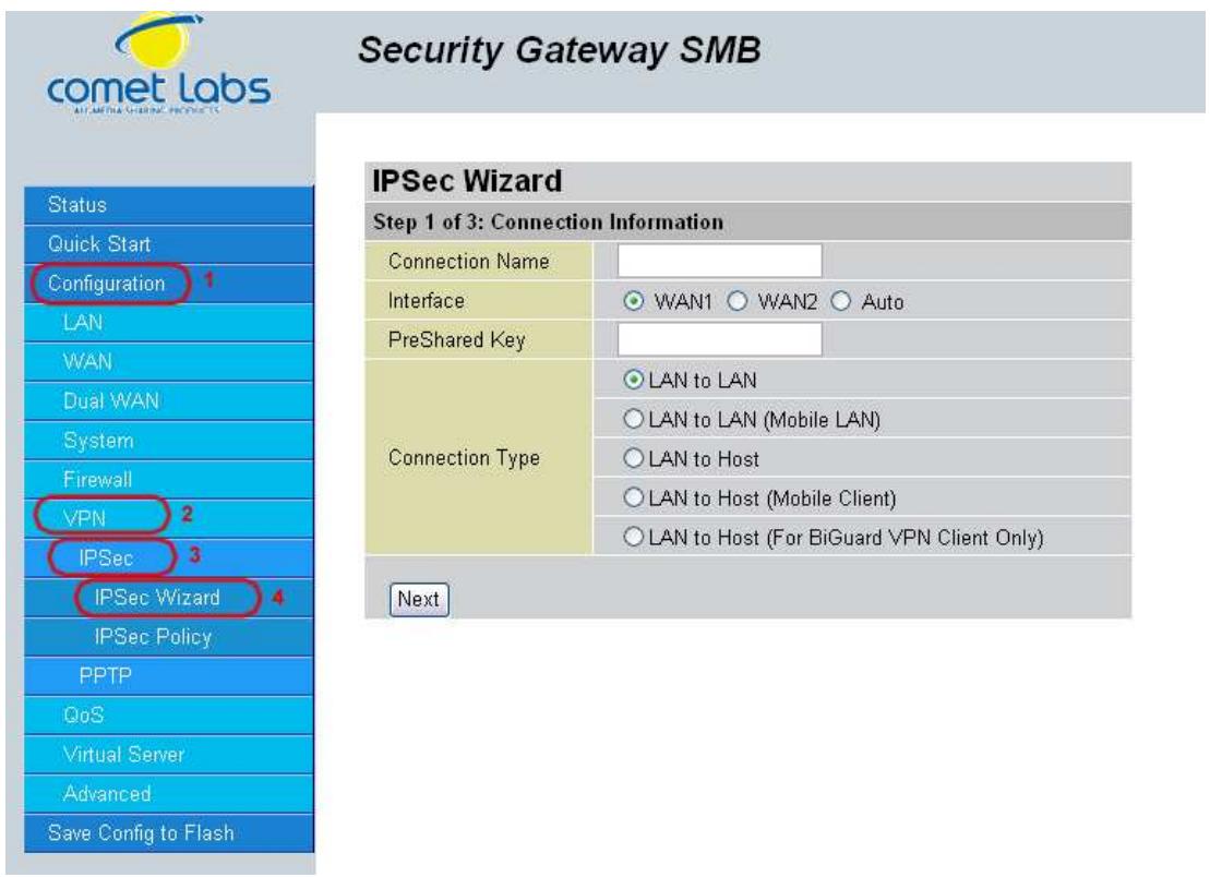
Connection Name: A user-defined name for the connection.
Interface: Select the interface the IPSec tunnel will apply to.
WAN1: Select interface WAN1
WAN2: Select interface WAN2
Auto: The device will automatically apply the tunnel to WAN1 or WAN2 depending on which WAN interface is active when the IPSec tunnel is being established. Note. Auto only applies to Fail Over mode. For Load Balance mode, please do not select "Auto". In Load Balance mode, Auto will be forced to WAN1 interface if Auto is selected.
Pre-shared Key: This is for the Internet Key Exchange (IKE) protocol. IKE is used to establish a shared security policy and authenticated keys for services (such as
IPSec) that require a key. Before any IPSec traffic can be passed, each router must be able to verify the identity of its peer. This can be done by manually entering the pre-shared key into both sides (router or hosts).
Connection Type:
There are 5 connection types:
(1)LAN to LAN: RF would like to establish an IPSec VPN tunnel with remote router using Fixed Internet IP or domain name by using main mode.
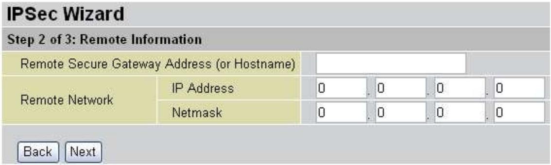
Secure Gateway Address (or Domain Name): The IP address or hostname of the remote VPN gateway.
Remote Network: The subnet of the remote network. Allows you to enter an IP address and netmask.
Back: Back to the Previous page.
Next: Go to the next page.
(2)LAN to Mobile LAN: RF would like to establish an IPSec VPN tunnel with remote router using Dynamic Internet IP by using aggressive mode.
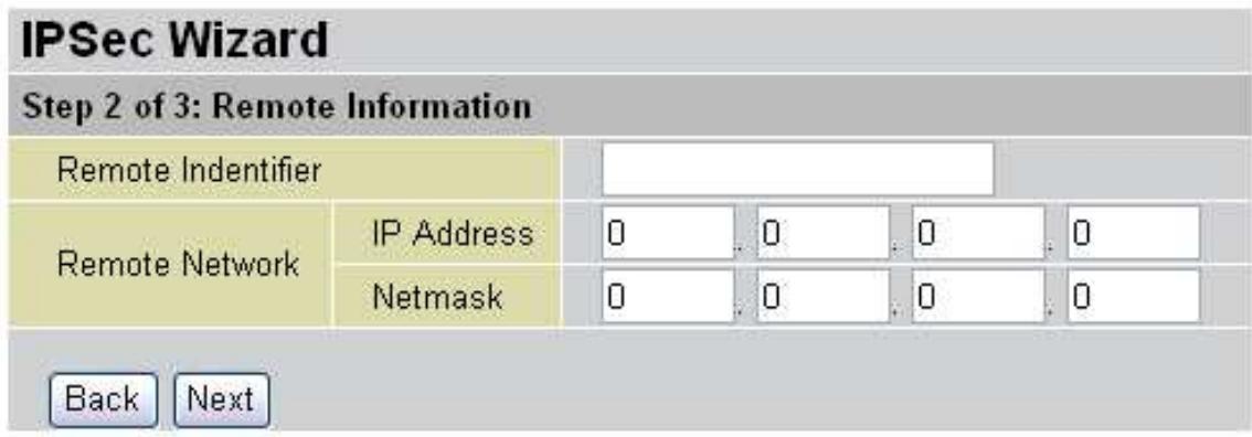
Remote Identifier: The Identifier of the remote gateway. According to the input value, the ID type will be auto-defined as IP Address, FQDN(DNS) or FQUN(E mail).
Remote Network: The subnet of the remote network. Allows you to enter an IP address and netmask.
Back: Back to the Previous page.
Next: Go to the next page.
(3)LAN to Host: RF would like to establish an IPSec VPN tunnel with remote client software using Fixed Internet IP or domain name by using main mode.
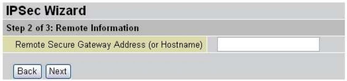
Secure Gateway Address (or Domain Name): The IP address or hostname of the remote VPN device that is connected and establishes a VPN tunnel.
Back: Back to the Previous page.
Next: Go to the next page.
(4)LAN to Mobile Host: RF would like to establish an IPSec VPN tunnel with remote client software using Dynamic Internet IP by using aggressive mode.
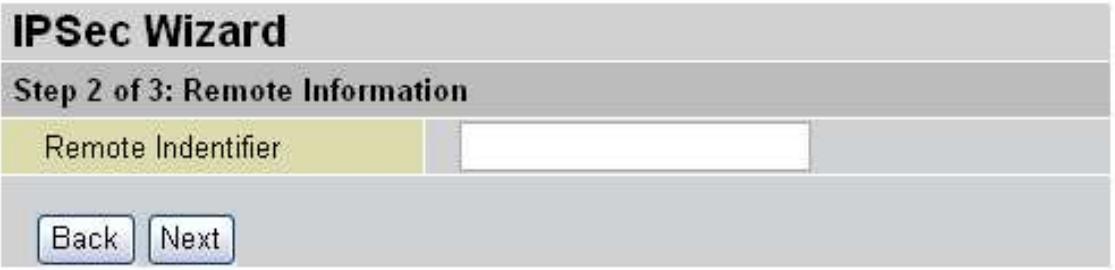
Remote Identifier: The Identifier of the remote gateway. According to the input value, the ID type will be auto-defined as IP Address, FQDN(DNS) or FQUN(E-mail).
Back: Back to the Previous page.
Next: Go to the next page.
(5)LAN to Host (for RF VPN Client only): RF would like to establish an IPSec VPN tunnel with RF VPN Client software C01 by using aggressive mode.
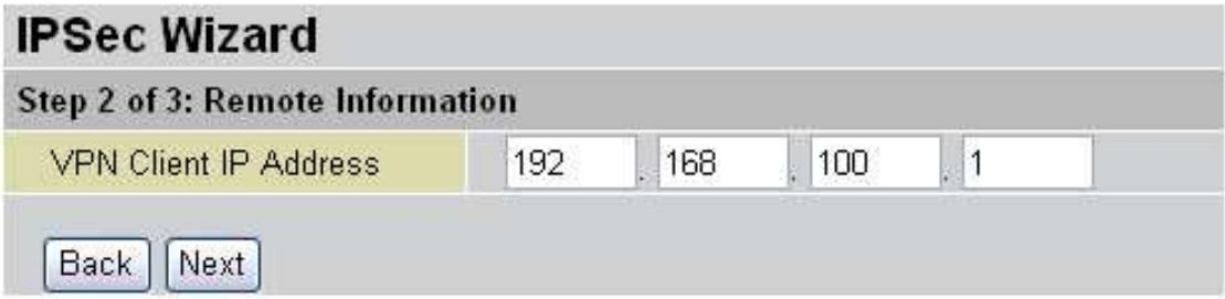
VPN Client IP Address: The VPN Client Address for RF VPN Client, this value will be applied on both remote ID and Remote Network as single address.
Back: Back to the Previous page.
Next: Go to the next page.
After your configuration is done, you will see a Configuration Summary.
Back: Back to the Previous page.
Done: Click Done to apply the rule.
4.4.6.1.2 IPSec Policy
IPSec is a set of protocols that enable Virtual Private Networks (VPN). VPN is a way to establish secured communication tunnels to an organization's network via the Internet.

Click Create to create a new IPSec VPN connection account.
Configuring a New VPN Connection
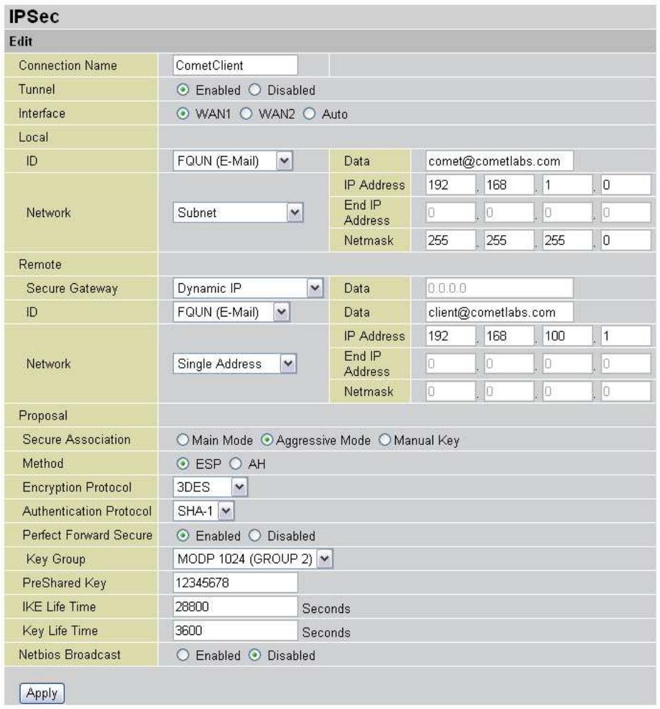
Connection Name: A user-defined name for the connection.
Tunnel: Select Enable to activate this tunnel. Select Disable to deactivate this tunnel.
Interface: Select the interface the IPSec tunnel will apply to.
WAN1: Select interface WAN1
WAN2: Select interface WAN2
Auto: The device will automatically apply the tunnel to WAN1 or WAN2 appending on which WAN interface is active when the IPSec tunnel is being established.
Note. Auto only applies to Fail Over mode. For Load Balance mode, please do not select "Auto". In Load Balance mode, Auto will be forced to WAN1 interface if Auto is selected.
Local: This section configures the local host.
ID: This is the identity type of the local router or host. Choose from the following four options:
WAN IP Address: Automatically use the current WAN Address as ID.
IP Address: Use an IP address format.
FQDN DNS(Fully Qualified Domain Name): Consists of a hostname and domain name. For example, WWW.VPN.COM is a FQDN. WWW is the host name, VPN.COM is the domain name. When you enter the FQDN of the local host, the router will automatically seek the IP address of the FQDN.
FQUN E-Mail(Fully Qualified User Name): Consists of a username and its domain name. For example, user@vpn.com is a FQUN. "user" is the username and "vpn.com" is the domain name.
Data: Enter the ID data using the specific ID type.
Network: Set the IP address, IP range, subnet, or address range of the local network.
Any Local Address: Will enable any local address on the network.
Subnet: The subnet of the local network. Selecting this option enables you to enter an IP address and netmask.
IP Range: The IP Range of the local network.
Single Address: The IP address of the local host.
Remote: This section configures the remote host.
Secure Gateway Address (or Domain Name): The IP address or hostname of the remote VPN device that is connected and establishes a VPN tunnel.
ID: The identity type of the local host. Choose from the following three options:
Remote IP Address: Automatically use the remote gateway Address as ID with ID type - IP Address.
IP Address: Use an IP address format.
FQDN DNS(Fully Qualified Domain Name): Consists of a hostname and domain name. For example, WWW.VPN.COM is a FQDN. WWW is the host name, VPN.COM is the domain name. When you enter the FQDN of the local host, the router will automatically seek the IP address of the FQDN.
FQUN E-Mail(Fully Qualified User Name): Consists of a username and its domain name. For example, user@vpn.com is a FQUN. "user" is the username and "vpn.com" is the domain name.
Data: Enter the ID data using the specific ID type.
Network: Set the subnet, IP Range, single address, or gateway address of the remote network.
Any Local Address: Will enable any local address on the network.
Subnet: The subnet of the remote network. Selecting this option allows you to enter an IP address and netmask.
IP Range: The IP Range of the remote network.
Single Address: The IP address of the remote host.
Gateway Address: The gateway address of the remote host.
Proposal:
Secure Association (SA): SA is a method of establishing a security policy between two points. There are three methods of creating SA, each varying in degrees of security and speed of negotiation:
Main Mode: Uses the automated Internet Key Exchange (IKE) setup; most secure method with the highest level of security.
Aggressive Mode: Uses the automated Internet Key Exchange (IKE) setup; mid-level security. Speed is faster than Main mode.
Manual Key: Standard level of security. It is the fastest of the three methods.
Method: There are two methods of checking the authentication information, AH (Authentication Header) and ESP (Encapsulating Security Payload). Use ESP for greater security so that data will be encrypted and authenticated. AH data will be authenticated but not encrypted.
Encryption Protocol: Select the encryption method from the pull-down menu. There are several options: DES, 3DES, and AES (128, 192 and 256). 3DES and AES are more powerful but increase latency.
DES: Stands for Data Encryption Standard. It uses a 56-bit encryption method.
3DES: Stands for Triple Data Encryption Standard. It uses a 168-bit encryption method.
AES: Stands for Advanced Encryption Standard. You can use 128, 192 or 256 bits as encryption method.
Authentication Protocol: Authentication establishes data integrity and ensures it is not tampered with while in transit. There are two options: Message Digest 5 (MD5), and Secure Hash Algorithm (SHA1). While slower, SHA1 is more resistant to brute-force attacks than MD5.
MD5: A one-way hashing algorithm that produces a 128-bit hash.
SHA1: A one-way hashing algorithm that produces a 160-bit hash.
Perfect Forward Secure: Choose whether to enable PFS using Diffie-Hellman public-key cryptography to change encryption keys during the second phase of VPN negotiation. This function will provide better security, but extends the VPN negotiation time. Diffie-Hellman is a public-key cryptography protocol that allows two parties to establish a shared secret over the Internet.
Pre-shared Key: This is for the Internet Key Exchange (IKE) protocol. IKE is used to establish a shared security policy and authenticated keys for services (such as IPSec) that require a key. Before any IPSec traffic can be passed, each router must be able to verify the identity of its peer. This can be done by manually entering the pre-shared key into both sides (router or hosts).
IKE Life Time: Allows you to specify the timer interval for renegotiation of the IKE security association. The value is in seconds, eg. 28800 seconds = 8 hours.
Key Life Time: Allows you to specify the timer interval for renegotiation of another key. The value is in seconds eg. 3600 seconds = 1 hour.
Netbios Broadcast: Allows RF to send local Netbios Broadcast packet through the IPSec Tunnel, please select Enable or Disable.
Click the Apply button to save your changes.
After you have created the IPSec connection, the account information will be displayed.
Name: This is the user-defined name of the connection.
Enable: This function activates or deactivates the IPSec connection.
Local Subnet: Displays IP address and subnet of the local network.
Remote Subnet: Displays IP address and subnet of the remote network.
Remote Gateway: This is the IP address or Domain Name of the remote VPN device that is connected and has an established IPSec tunnel.
IPSec Proposal: This is the selected IPSec security method.
For examples on how to apply IPSec to your network, see Appendix F: IPSec Logs and Events.
4.4.6.2 PPTP
PPTP is a set of protocols that enable Virtual Private Networks (VPN). VPN is a way to establish secured communication tunnels to an organization's network via the Internet.
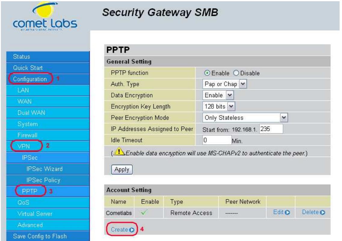
PPTP function: Select Enable to activate PPTP Server. Disable to deactivate PPTP Server function.
Auth. Type: The authentication type, Pap or Chap, PaP, Chap.
Data Encryption: Select Enable or Disable the Data Encryption.
Encryption Key Length: Auto, 40 bits or 128 bits.
Peer Encryption Mode: Only Stateless or Allow Stateless and Stateful.
IP Addresses Assigned to Peer Start from: 192.168.1.x: please input the IP assigned
range from 1 ~ 254 (except RF 30's LAN IP address with 192.168.1.254 as
RF 30's default LAN IP address and IP pool range of DHCP server settings with
100~199 as RF 30's default DHCP IP pool range.)
Idle Timeout " " Min: Specify the time for remote peer to be disconnected without any activities, from 0~120.
Click Create to create a new PPTP VPN connection account.
Security Gateway SMB
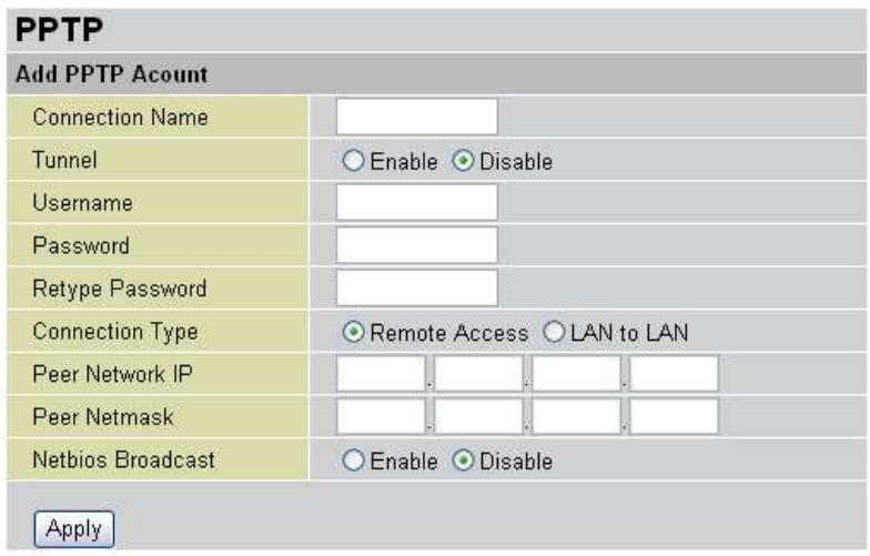
Connection Name: A user-defined name for the connection.
Tunnel: Select Enable to activate this tunnel. Select Disable to deactivate this tunnel.
Username: Please input the username for this account.
Password: Please input the password for this account.
Retype Password: Please repeat the same password as previous field.
Connection Type: Select Remote Access for single user, Select LAN to LAN for remote gateway.
Peer Network IP: Please input the IP for remote network.
Peer Netmask: Please input the Netmask for remote network.
Netbios Broadcast: Allows RF to send local Netbios Broadcast packets through the PPTP Tunnel, please select Enable or Disable.
4.4.7 QoS
The RF30 can optimize your bandwidth by assigning priority to both inbound and outbound data with QoS. This menu allows you to configure QoS for both inbound and outbound traffic.
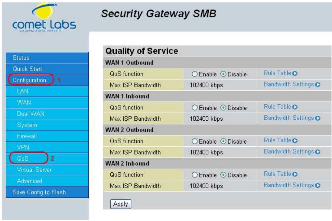
The first menu screen gives you an overview of which WAN ports currently have QoS active, and the bandwidth settings for each.
WAN1 Outbound:
QoS Function: QoS status for WAN1 outbound. Select Enable to activate QoS for WAN1's outgoing traffic. Select Disable to deactivate.
Max ISP Bandwidth: The maximum bandwidth afforded by the ISP for WAN1's outbound traffic.
WAN1 Inbound:
QoS Function: QoS status for WAN1 inbound. Select Enable to activate QoS for WAN1's incoming traffic. Select Disable to deactivate.
Max ISP Bandwidth: The maximum bandwidth afforded by the ISP for WAN1's inbound traffic.
WAN2 Outbound:
QoS Function: QoS Status for WAN2 outbound. Select Enable to activate QoS for WAN2's outgoing traffic. Select Disable to deactivate.
Max ISP Bandwidth: The maximum bandwidth afforded by the ISP for WAN2's outbound traffic.
WAN2 Inbound:
QoS Function: QoS Status for WAN2 inbound. Select Enable to activate QoS for WAN2's incoming traffic. Select Disable to deactivate.
Max ISP Bandwidth: The maximum bandwidth afforded by the ISP for WAN2's inbound traffic.
Creating a New QoS Rule
To get started using QoS, you will need to establish QoS rules. These rules tell the RF30 how to handle both incoming and outgoing traffic. The following example shows you how to configure WAN1 Outbound QoS. Configuring the other traffic types follows the same process.
To make a new rule, click Rule Table. This will bring you to the Rule Table which displays the rules currently in effect.
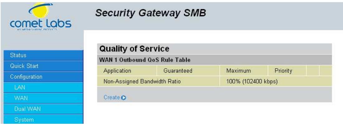
Next, click Create to open the QoS Rule Configuration window.
Security Gateway SMB
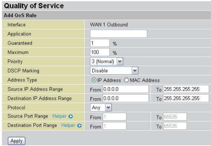
Interface: The current traffic type. This can be WAN1 (outbound, inbound) and WAN2 (outbound, inbound).
Application: User defined application name for the current rule.
Packet Type: The type of packet this rule applies to. Choose from Any, TCP, UDP, or ICMP.
Guaranteed: The guaranteed amount of bandwidth for this rule as a percentage.
Maximum: The maximum amount of bandwidth for this rule as a percentage.
Priority: The priority assigned to this service. Select a value from 0 to 6, 0 being highest.
DSCP Marking: Used to classify traffic. Select from Best Effort, Premium, Gold Service (High Medium, Low), Silver (H,M,L), and Bronze (H,M,L).
Address Type: The type of address this rule applies to. Select IP Address or MAC Address.
For IP Address...
Source IP Address Range: The range of source IP Addresses this rule applies to.
Destination IP Address Range: The range of destination IP Addresses this rule applies to.
Source Port Range: The range of source ports this rule applies to.
Destination Port Range. The range of destination ports this rule applies to.
Click Apply to save your changes.
For MAC Address...
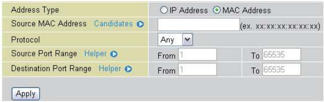
Source MAC Address: The source MAC Address of the device this rule applies to.
Source Port Range: The range of source ports this rule applies to.
Destination Port Range: The range of destination ports this rule applies to.
4.4.8 Virtual Server
In TCP/IP and UDP networks, a port is a 16-bit number used to identify which application program (usually a server) incoming connections should be delivered to. Some ports have numbers that are pre-assigned to them by the Internet Assigned Numbers Authority (IANA), and these are referred to as "well-known ports". Servers follow the well-known port assignments so clients can locate them.
If you wish to run a server on your network that can be accessed from the WAN (i.e. from other machines on the Internet that are outside your local network), or any application that can accept incoming connections (e.g. peer-to-peer applications) and are using NAT (Network Address Translation), then you will usually need to configure your router to forward these incoming connection attempts using specific ports to the PC on your network running the application. You will also need to use port forwarding if you want to host an online game server. The reason for this is that when using NAT, your publicly accessible IP address will be used by and point to your router, which then needs to deliver all traffic to the private IP addresses used by your PCs. Please see the WAN Configuration section of this manual for more information on NAT.
The RF30 can also be configured as a virtual server so that remote users accessing services such as Web or FTP services via the public (WAN) IP address can be automatically redirected to local servers in the LAN network. Depending on the requested service (TCP/UDP port number), the device redirects the external service request to the appropriate server within the LAN network.
4.4.8.1 DMZ
The DMZ Host is a local computer exposed to the Internet. When setting a particular internal IP address as the DMZ Host, all incoming packets will be checked by the Firewall and NAT algorithms then passed to the DMZ host, when a packet received does not use a port number used by any other Virtual Server entries.
Caution: Such Local computer exposure to the Internet may face a variety of security risks.
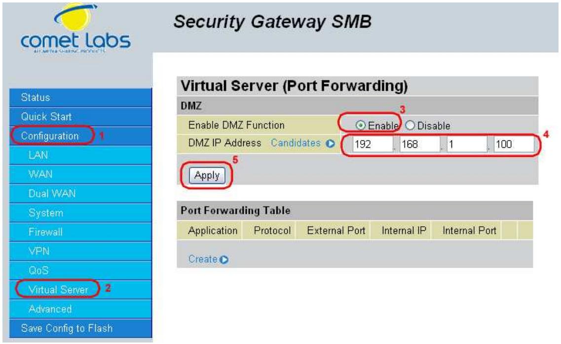
Enable DMZ function:
Enable: Activates your router's DMZ function.
Disable: Default setting. Enables the DMZ function.
DMZ IP Address: Give a static IP address to the DMZ Host when the Enable radio button is selected. Be aware this IP will be exposed to the WAN/Internet.
Select the Apply button to apply your changes.
4.4.8.2 Port Forwarding Table
Because NAT can act as a "natural" Internet firewall, your router protects your network from being accessed by outside users, as all incoming connection attempts will point to your router unless you specifically create Virtual Server entries to forward those ports to a PC on your network.
When your router needs to allow outside users to access internal servers, e.g. a web server, FTP server, Email server or game server, the router can act as a "virtual server". You can set up a local server with a specific port number for the service to use, e.g. web/HTTP (port 80), FTP (port 21), Telnet (port 23), SMTP (port 25), or POP3 (port 110). When an incoming access request is received, it will be forwarded to the corresponding internal server.
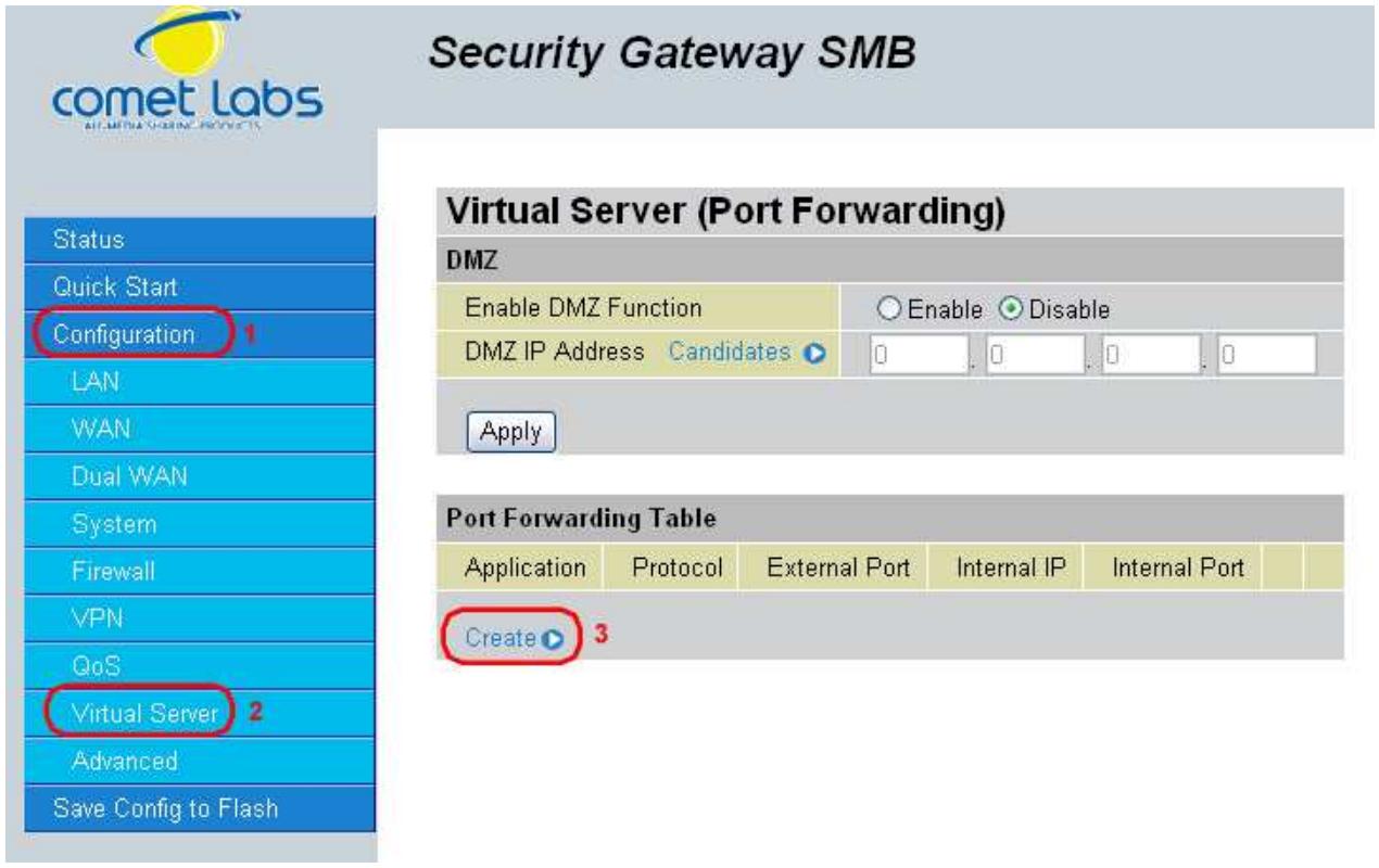
Click Create to add a new port forwarding rule. There are two port forwarding modes: Port Range Mapping and Port Redirection.
4.4.8.2.1 Port Range Mapping
This function allows any incoming data addressed to a range of service port numbers (from the Internet/WAN Port) to be re-directed to a particular LAN private/internal IP address. This option gives you the ability to handle applications that use more than one port such as games and audio/video conferencing.
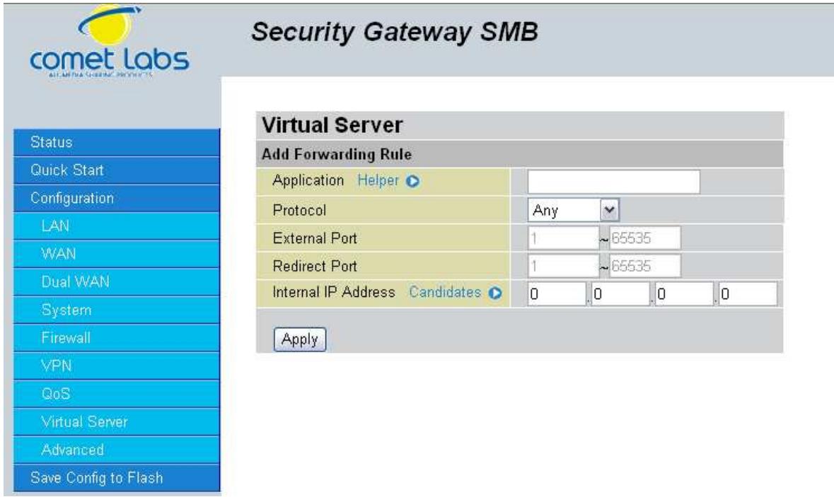
Forwarding Mode: Click the Port Range Mapping radio button to change to Port Range Mapping mode.
Internal IP Address: Enter the LAN server/host IP address that the service request from the Internet will be sent to.
NOTE: You need to give your LAN server/host a static IP address for the Virtual Server to work properly.
External Port Range: Enter the port number of the service that will be sent to the Internal IP address.
Click Apply to save your changes.
4.4.8.2.2 Port Redirect
This function allows any incoming data addressed to a specific service port number (from the Internet/WAN Port) to be redirected to an internal IP address.
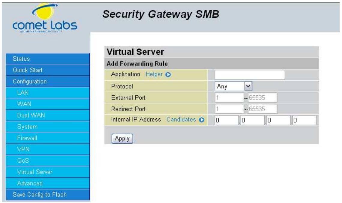
Forwarding Mode: Click the Port Redirector radio button to change to Port Redirector mode.
Internal IP Address: Enter the LAN server/host IP address that the service request from the Internet will be sent to.
NOTE: You need to give your LAN server/host a static IP address for the Virtual Server to work properly.
External Port: Enter the port number of the service that will be sent to the Internal IP address.
Internal Port: Enter a new port number for the service that will be sent to the Internal IP address.
Click Apply to save your changes.
Using port forwarding does have security implications, as outside users will be able to connect to PCs on your network. For this reason, using specific Virtual Server entries just for the ports your application requires, instead of using DMZ is recommended.
4.4.9 Advanced
Configuration options within the Advanced section are for users who wish to take advantage of the more advanced features of the RF30. Users who do not understand the features should not attempt to reconfigure their router, unless advised to do so by support staff.
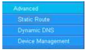
There are three items within the Advanced section: Static Route, Dynamic DNS and Device Management.
4.4.9.1 Static Route
The static route settings enable the router to route IP packets to another network ( subnet). The routing table stores the routing information so the router knows where to redirect the IP packets.
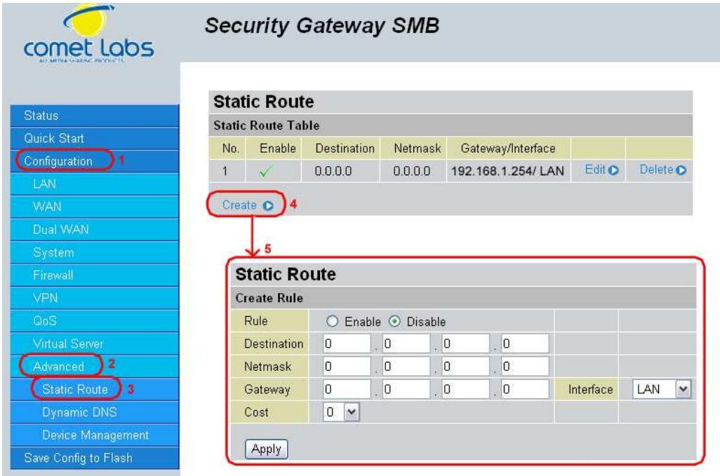
Click on Static Route and then click Create to add a routing table.
Destination: This is the destination subnet IP address.
Netmask: This is the subnet mask of the destination IP addresses based on above destination subnet IP.
Gateway: This is the gateway IP address to which packets are to be forwarded.
Interface: Select the interface through which packets are to be forwarded.
Cost: This is the same meaning as Hop.
Click Apply to save your changes.
4.4.9.2 Dynamic DNS
The Dynamic DNS function allows you to alias a dynamic IP address to a static hostname, allowing users whose ISP does not assign them a static IP address to use a domain name. This is especially useful when hosting servers via your WAN connection, so that anyone wishing to connect to you may use your domain name, rather than having to use a dynamic IP address that changes periodically. This dynamic IP address is the WAN1/WAN2 IP address of the router, which is assigned to you by your ISP. Click Edit in the Dynamic DNS Settings Table to set related parameters for a specific interface.

You will first need to register and establish an account with the Dynamic DNS provider using their website,
Example: DYNDNS
http://www.dyndns.org/
(RF30 supports several Dynamic DNS providers, such as www.dyndns.org, www.orgdns.org, www.dhs.org, www.dyns.cx, www.3domain.hk, www.dyndns.org, www.3322.org)
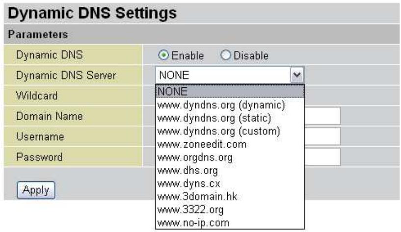
Dynamic DNS:
Disable: Check to disable the Dynamic DNS function.
Enable: Check to enable the Dynamic DNS function. The following fields will be activated and required:
Dynamic DNS Server: Select the DDNS service you have established an account with.
Wildcard: Select this check box to enable the DYNDNS Wildcard.
Domain Name: Enter your registered domain name for this service.
Username: Enter your registered user name for this service.
Password: Enter your registered password for this service.
Click Apply to save your changes.
4.4.9.3 Device Management
The Device Management Advanced Configuration settings allow you to control your router's security options and device monitoring features.
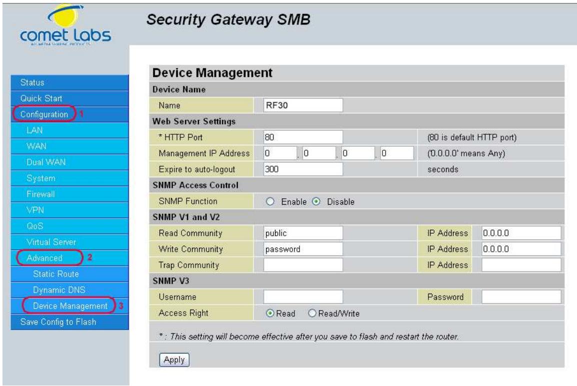
Device Name
Name: Enter a name for this device.
Web Server Settings
HTTP Port: This is the port number the router's embedded web server (for web-based configuration) will use. The default value is the standard HTTP port, 80. Users may specify an alternative if, for example, they are running a web server on a PC within their LAN.
Management IP Address: You may specify an IP address allowed to logon and access the router's web server. Setting the IP address to 0.0.0.0 will disable IP address restrictions, allowing users to login from any IP address.
Expire to auto-login: Specify a time frame for the system to auto-login the user's configuration session.
Example: User A changes HTTP port number to 100, specifies their own IP address of 192.168.1.100 and sets the logout time to be 100 seconds. The router will only allow User A access from the IP address 192.168.1.100 to logon to the Web GUI by typing: http://192.168.1.254:100 in their web browser. After 100 seconds, the device will automatically logout User A.
4.5 Save Configuration To Flash
After changing the router's configuration settings, you must save all of the configuration parameters to flash memory to avoid them being lost after turning off or resetting your router. Click Apply to write your new configuration to flash memory.
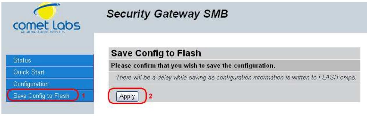
4.6Logout
To exit the router's web interface, click Logout. Please ensure that you have saved your configuration settings before you logout.

Be aware that the router is restricted to only one PC accessing the web configuration interface at a time. Once a PC has logged into the web interface, other PCs cannot gain access until the current PC has logged out. If the previous PC forgets to logout, the second PC can access the page after a user-defined period (5 minutes by default). You can modify this value using the Advanced > Device Management section of the Web Configuration Interface. Please see the Advanced section of this manual for more information.
Chapter 5: Troubleshooting
5.1 Basic Functionality
This section deals with issues regarding your RF30's basic functions.
5.1.1 Router Won't Turn On
If the Power and other LEDs fail to light when your RF30 is turned on:
- Make sure that the power cord is properly connected to your firewall and that the power supply adapter is properly connected to a functioning power outlet.
- Check that you are using the 12VDC power adapter supplied by Cometlabs for this product.
If the error persists, you may have a hardware problem, and should contact technical support.
5.1.2 LEDs Never Turn Off
When your RF30 is turned on, the LEDs turn on for about 10 seconds and then turn off. If all the LEDs stay on, there may be a hardware problem.
If all LEDs are still on one minute after powering up:
- Cycle the power to see if the router recovers.
- Clear the configuration to factory defaults.
If the error persists, you may have a hardware problem, and should contact technical support.
5.1.3 LAN or Internet Port Not On
If either the LAN LEDs or Internet LED do not light when the Ethernet connection is made, check the following:
- Make sure each Ethernet cable connection is secure at the firewall and at the hub or workstation.
- Make sure that power is turned on to the connected hub or workstation.
- Be sure you are using the correct cable. When connecting the firewall's Internet port to a cable or DSL modem, use the cable that was supplied with the cable or DSL modem. This cable could be a standard straight-through Ethernet cable or an Ethernet crossover cable.
5.1.4 Forgot My Password
Try entering the default User Name and Password:
User Name: admin
Password: admin
Please note that both the User Name and Password are case-sensitive.
If this fails, you can restore your RF30 to its factory default settings by holding the Reset button on the back of your router until the Status LED begins to blink. Then enter the default User Name and Password to access your router.
5.2 LAN Interface
Refer to this section for issues relating to the RF30's LAN Interface.
5.2.1 Can't Access RF30 from the LAN
If there is no response from the RF30 from the LAN:
- Check your Ethernet cable types and each connection.
- Make sure the computer's Ethernet adapter is installed and functioning properly.
If the error persists, you may have a hardware problem, and should contact technical support.
5.2.2 Can't Ping Any PC on the LAN
If PCs connected to the LAN cannot be pinged:
- Check the 10/100 LAN LEDs on the RF30's front panel. One of these LEDs should be on. If they are both off, check the cables between the RF30 and the hub or PC.
- Check the corresponding LAN LEDs on your PC's Ethernet device are on.
- Make sure that driver software for your PC's Ethernet adapter and TCP/IP software is correctly installed and configured on your PC.
- Verify the IP address and the subnet mask of the RF30 and the computers are on the same subnet.
5.2.3 Can't Access Web Configuration Interface
If you are having trouble accessing the RF30's Web Configuration Interface from a PC connected to the network:
- Check the connection between the PC and the router.
- Make sure your PC's IP address is on the same subnet as the router.
-
If your RF30's IP address has changed and you don't know the current IP address, reset the router to factory defaults by holding the Reset button on the back of your router for 6 seconds. This will reset the router's IP address to 192.168.1.254.
-
Check to see if your browser had Java, JavaScript, or ActiveX enabled. If you are using Internet Explorer, click Refresh to ensure that the Java applet is loaded.
- Try closing the browser and re-launching it.
- Make sure you are using the correct User Name and Password. User Names and Passwords are case-sensitive, so make sure that CAPS LOCK is not on when entering this information.
-
Try clearing your browser's cache.
-
With Internet Explorer, click Tools > Internet Options.
- Under the General tab, click Delete Files.
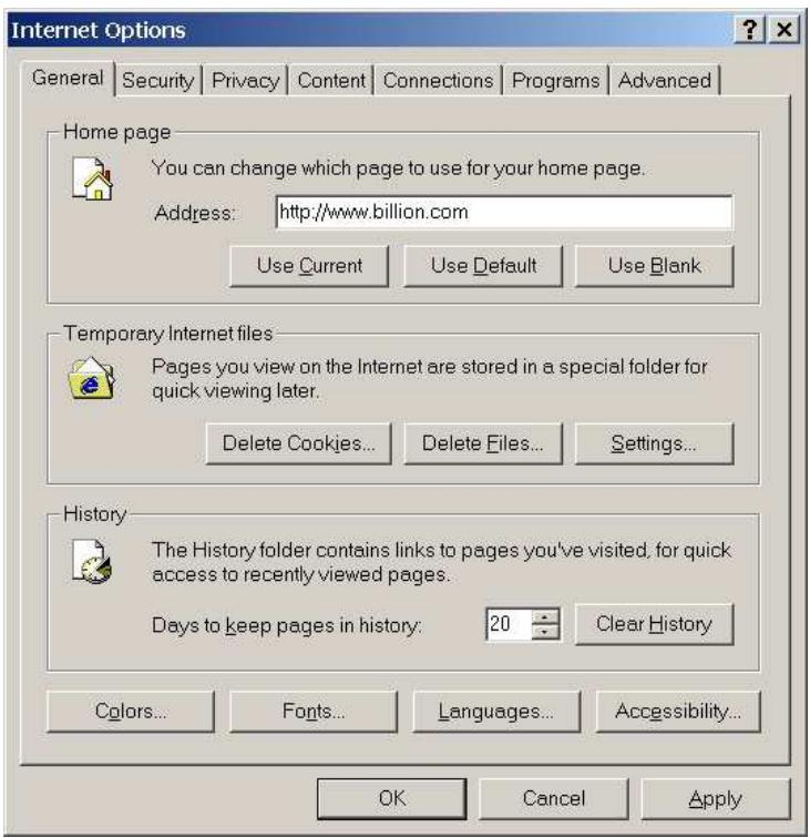
- Make sure that the Delete All Offline Content checkbox is checked, and click OK.
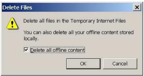
-
Click OK under Internet Options to close the dialogue.
-
In Windows, type arp -d at the command prompt to clear you computer's ARP table.
5.2.3.1 Pop-up Windows
To use the Web Configuration Interface, you need to disable pop-up blocking. You can either disable pop-up blocking, which is enabled by default in Windows XP Service Pack 2, or create an exception for your RF30's IP address.
Disabling All Pop-ups
In Internet Explorer, select Tools > Pop-up Blocker and select Turn Off Pop-up Blocker.
You can also check if pop-up blocking is disabled in the Pop-up Blocker section in the Privacy tab of the Internet Options dialogue.
- In Internet Explorer, select Tools > Internet Options.
- Under the Privacy tab, clear the Block pop-ups checkbox and click Apply to save your changes.
Enabling Pop-up Blockers with Exceptions
If you only want to allow pop-up windows with your RF30:
- In Internet Explorer, select Tools > Internet Options.
- Under the Privacy tab, click Settings to open the Pop-up Blocker Settings dialogue.
- Enter the IP address of your router.
- Click Add to add the IP address to the list of Allowed sites.
- Click Close to return to the Privacy tab of the Internet Options dialogue.
- Click Apply to save your changes.
5.2.3.2 Javascrits
If the Web Configuration Interface is not displaying properly in your browser, check to make sure that JavaScripts are allowed.
- In Internet Explorer, click Tools > Internet Options.
- Under the Security tab, click Custom Level.
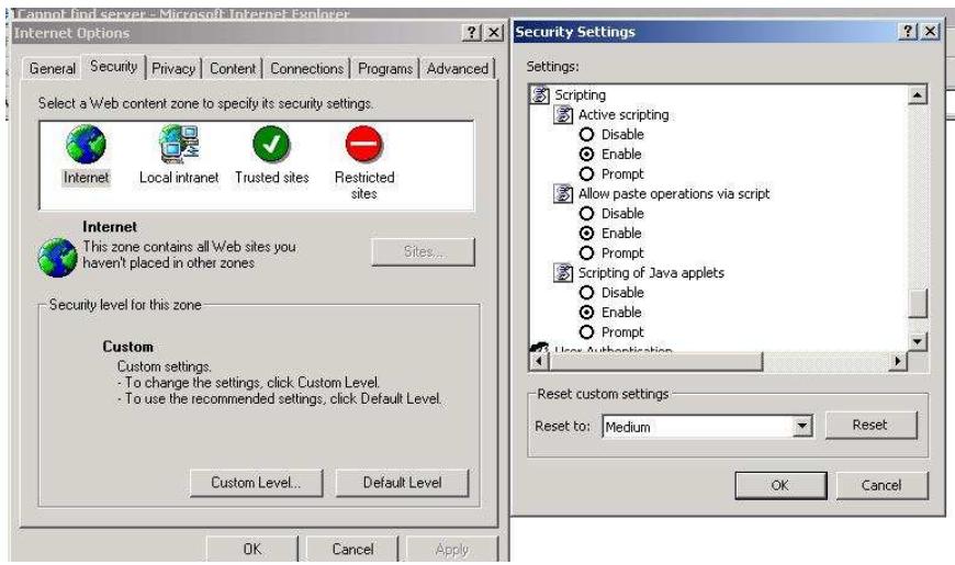
- Under Scripting, check to see if Active scripting is set to Enable.
- Ensure that Scripting of Java applets is set to Enabled.
- Click OK to close the dialogue.
5.2.3.3 Java Permissions
The following Java Permissions should also be given for the Web Configuration Interface to display properly:
- In Internet Explorer, click Tools > Internet Options.
- Under the Security tab, click Custom Level.
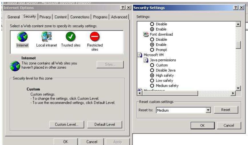
- Under Microsoft VM*, make sure that a safety level for Java permissions is selected.
- Click OK to close the dialogue.
NOTE: If Java from Sun Microsystems is installed, scroll down to Java (Sun) and ensure that the checkbox is filled.
5.3 WAN Interface
If you are having problems with the WAN Interface, refer to the tips below.
5.3.1 Can't Get WAN IP Address from the ISP
If the WAN IP address cannot be obtained from the ISP:
- If you are using PPPoE or PPTP encapsulation, you will need a user name and password. Ensure that you have entered the correct Service Type, User Name, and Password. Note that user names and passwords are case-sensitive.
- If your ISP requires MAC address authentication, clone the MAC address from your PC on the LAN as the RF30's WAN MAC address.
- If your ISP requires host name authentication, configure your PC's name as the RF30's system name.
5.4 ISP Connection
Unless you have been assigned a static IP address by your ISP, your RF30 will need to request an IP address from the ISP in order to access the Internet. If your RF30 is unable to access the Internet, first determine if your router is able to obtain a WAN IP address from the ISP.
To check the WAN IP address:
- Open your browser and choose an external site (i.e. www.Cometlabs.com).
- Access the Web Configuration Interface by entering your router's IP address (default is 192.168.1.254).
- The WAN IP Status is displayed on the first page.
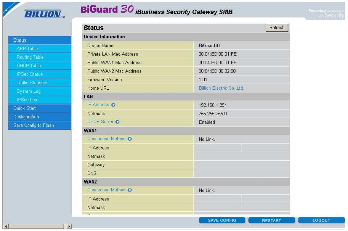
- Check to see that the WAN port is properly connected to the ISP. If a Connected by (±bx) where (±bx) is your connection method is not shown, your router has not successfully obtained an IP address from your ISP.
If an IP address cannot be obtained:
- Turn off the power to your cable or DSL modem.
- Turn off the power to your RF30.
- Wait five minutes and power on your cable or DSL modem.
- When the modem has finished synchronizing with the ISP (generally shown by LEDs on the modem), turn on the power to your router.
If an IP address still cannot be obtained:
- Your ISP may require a login program. Consult your ISP whether they require PPPoE or some other type of login.
- If your ISP requires a login, check to see that your User Name and Password are entered correctly.
- Your ISP may check for your PC's host name. Assign the PC Host Name of your ISP account as your PC's host name on the router.
- Your ISP may check for your PCs MAC address. Either inform your ISP that you have purchased a new network device or ask them to use your router's MAC address, or configure your router to spoof your PC's MAC address.
If an IP address can be obtained, but your PC cannot load any web pages from the Internet:
- Your PC may not recognize DNS server addresses. Configure your PC manually with DNS addresses.
- Your PC may not have the router correctly configured as its TCP/IP gateway.
5.5 Problems with Date and Time
If the date and time is not being displayed correctly, be sure to set it for your RF30 via the Web Configuration Interface. Both date and time can be found under Configuration > System > Time Zone.
5.6 Restoring Factory Defaults
You can restore your RF30 to its factory settings by holding the Reset button on the back of your router until the Status LED begins to blink. This will reset your router to its default settings.

Appendix A: Product Specifications

Availability and Resilience
- Dual-WAN ports
- Load balancing for increased bandwidth of inbound and outbound traffic
- Automatic failover to redirect the packet when one broadband connection is broken. It will keep your Internet connection always online whenever one connection should fail.
Virtual Private Network
- IPSec VPN, supports up to 30 IPSec tunnels
- VPN performance is up to 30 Mbps
- Manual key, Internet Key Exchange (IKE) authentication and Key Management
- Authentication (MD5 / SHA-1)
- DES/3DES encryption
- AES 128/192/256 encryption
- IP Authentication Header (AH)
- IP Encapsulating Security Payload (ESP)
- Dynamic VPN (FQDN) support
- Supports remote access and office-to-office IPSec Connections
Firewall
- Stateful Packet Inspection (SPI) and Denial of Service (DoS) prevention
- Packet filter un-permitted inbound (WAN)/Inbound
- (LAN) Internet access by IP address, port number and packet type
- Email alert and logs of attack
Content Filtering
- URL Filter settings prevent user access to certain sites on the Internet
- Java Applet/Active X/Cookie Blocking
Quality of Service Control
- Supports DiffServ approach
- Traffic prioritization and bandwidth management based-on IP protocol, port number and IP or MAC address
Web-Based Management
- Easy-to-use WEB interface
- Firmware upgradeable via WEB interface
- Local and remote management via HTTP & HTTPS
Network Protocols and Features
- Web Diagnostics
- System Logs
- PPPoE, PPTP, Big Pond and DHCP client connections to the ISP
- NAT, static routing and RIP-2
- Dynamic Domain Name System (DDNS)
- Virtual Server and DMZ
- DHCP Server
- NTP
Physical Interface
Ethernet WAN 2 ports (10/100 Base-T), support Auto-Crossover (MDI/MDIX)
Ethernet LAN 8 ports (10/100 Base-T) switch support Auto-Crossover (MDI/MDIX)
Physical Specifications
Dimensions: 14.41'' x 6.53'' x 1.38'' (366mm x 166 mm x 35mm)
Power Requirement
Input: 12VDC, 1A
Operating Environment
- Operating temperature: 0 40 degrees Celsius
- Storage temperature: -20 70 degrees Celsius
- Humidity: 20 95% non-condensing
Appendix B: Customer Support
Most problems can be solved by referring to the Troubleshooting section in the User's Manual. If you cannot resolve the problem with the Troubleshooting chapter, please contact the dealer where you purchased this product.
Worldwide
http://www.Cometlabs.com/
Appendix C: FCC Interference Statement
This device complies with Part 15 of FCC rules. Operation is subject to the following two conditions:
- This device may not cause harmful interference.
- This device must accept any interference received, including interference that may cause undesired operations.
This equipment has been tested and found to comply with the limits for a Class B digital device pursuant to Part 15 of the FCC Rules. These limits are designed to provide reasonable protection against harmful interference in a commercial environment.
If this equipment does cause harmful interference to radio/television reception, which can be determined by turning the equipment off and on, the user is encouraged to try to correct the interference by one or more of the following measures:
- Reorient or relocate the receiving antenna.
- Increase the separation between the equipment and the receiver.
- Connect the equipment into an outlet on a circuit different from that to which the receiver is connected.
- Consult the dealer or an experienced radio/TV technician for help.
Notice:
Changes or modifications not expressly approved by the party responsible for compliance could void the user's authority to operate the equipment.
Appendix D: Network, Routing, and Firewall Basics
D.1 Network Basics
D.1.1 IP Addresses
With the number of TCP/IP networks interconnected across the globe, ensuring that transmitted data reaches the correct destination requires each computer on the Internet has a unique identifier. This identifier is known as the IP address. The Internet Protocol (IP) uses a 32-bit address structure, and the address is usually written in dot notation.
A typical IP address looks like this:
198.25.12.8
The 32 bits of the address are subdivided into two parts. The first part of the address identifies the network, while the second part identifies the host node or station on the network. How the address is divided depends on the address range and the application.
The five standard IP address classes each have different methods to determine the network and host sections of the address, which makes multiple hosts on a network possible. TCP/IP software identifies each address class by reading a unique bit pattern that precedes each address type. Once the address class has been recognized, the software can then correctly determine the addresses' host section. With this structure, IP addresses can uniquely identify each network and node.
D.1.1.1 Net mask
With each address class, the size of the two subdivided parts (network address and host address) is implied by the class. A net mask associated with an IP address can also express this partitioning. A net mask 32-bit quantity yields the network address when combined with an IP address. As an example, the net masks for Class A, B, and C are 255.0.0.0, 255.255.0.0, and 255.255.255.0 respectively.
Instead of dotted-decimal notation, the net mask can also be written in terms of the number of ones from the left. This number is added to the IP address, following a backward slash (/). For example, a typical Class C address could be written as 192.168.234.245/24, which means that the net mask is 24 ones followed by 8 zeros. (11111111 11111111 11111111 00000000).
D.1.1.2 Subnet Addressing
Subnet addressing enables the split of one IP network address into multiple physical networks. These smaller networks are called subnetworks, and these subnetworks can make efficient use of each address when compared to needing a different network number at each end of a routed link. This technique is especially useful in smaller network environments, such as small office LANs.
A Class B address provides 16 bits of node numbers, which enable 65,536 nodes. Since most organizations don't require such a large number of nodes, the free bits can be reassigned with subnet addressing.
Multiple Class C addresses can be made from a Class B address. For example, the IP address of 172.20.0.0 allows eight extra bits to use as a subnet address, since node addresses are limited to a maximum of 255. The IP address of 172.20.52.212 would be read as IP network address 172.20, subnet number 52, and node number 212.
Besides extending the number of available addresses, this technique also allows a network manager to design an address scheme for the network by using different subnets. This can be useful when trying to distinguish other geographical locations in the network or other departments in the organization.
D.1.1.3 Private IP Addresses
When isolated from the Internet, the hosts on your local network may be assigned IP addresses with no conflicts. However, the Internet Assigned Numbers Authority (IANA) has reserved several blocks of IP addresses for private networks. These include:
10.0.0.0 - 10.255.255.255
172.16.0.0 - 172.16.255.255
192.168.0.0 - 192.168.255.255
When assigning IP addresses to your private network, be sure to use IP addresses from these ranges.
D.1.2 Network Address Translation (NAT)
Traditionally, multiple PCs that needed simultaneous Internet access also required a range of IP addresses from the Internet Service Provider (ISP). Not only was this method very costly, but the number of available IP addresses for PCs is limited. Instead, the RF30 uses a type of address sharing called Network Address Translation to grant Internet access to several PCs on the same network through the same Internet account. This method translates internal IP addresses to a single address that is unique on the Internet. This unique address can either be fixed or dynamic, depending on the type of Internet account, and the internal LAN IP addresses may also be either private or registered addresses.
NAT also offers firewall-like protection to your network, since internal LAN addresses are shielded from the public Internet. All incoming traffic to the public IP address is handled by the router, which means added security for your network from intruders. If a particular PC on your LAN requires access from outside PCs, you can use port forwarding to accomplish this. For information on how to configure port forwarding on the RF30, refer to the Virtual Server section of Chapter 4: Router Configuration.
D.1.3 Dynamic Host Configuration Protocol (DHCP)
If the PCs on a LAN require access to the Internet, each PC must be configured with an IP address, a gateway address, and one or more DNS server addresses. Rather than configuring each PC manually, you can instead configure a network device to act as a Dynamic Host Configuration Protocol (DHCP) server. PCs on the network can automatically obtain IP addresses from a list of addresses stored on the DHCP server. In addition, other information such as gateway and DNS address can also be assigned with a DHCP server. When connecting to the ISP, the RF30 also functions as a DHCP client. The RF30 can automatically obtain an IP address, subnet mask, gateway address, and DNS server addresses if the ISP assigns this information via DHCP.
D.2 RouterBasics
D.2.1 What is a Router?
A router is a device that forwards data packets along networks. A router is connected to at least two networks. Usually, this is a LAN and a WAN that is connected to an ISP network. Routers are located at gateways, the places where two or more networks connect. Routers use headers and forwarding tables to determine the best path for forwarding the packets, and they use protocols to communicate with each other and configure the best route between any two hosts.
Routers can vary in performance and scale, the types of physical WAN connection they support, and the number of routing protocols supported. The RF30 offers a convenient and powerful way for small-to-medium businesses to connect their networks.
D.2.2 Why use a Router?
While large bandwidth can easily and inexpensively be provided in a LAN, having high bandwidth between a LAN and the Internet can be prohibitively expensive. Because of this, Internet access is usually done through a slower WAN link, such as a cable or DSL modem. To efficiently use this slower connection, a router acts as a mechanism for selecting and transmitting data meant for the Internet. By using a router, organizations can enjoy relatively inexpensive Internet access, while maintaining a high-speed local area network.
D.2.3 Routing Information Protocol (RIP)
Routing Information Protocol (RIP) is an interior gateway protocol that specifies how routers exchange routing table information. Routers periodically update each other with RIP, changing their routing tables when necessary.
The RF30 supports the RIP protocol. RIP also supports subnet and multicast protocols. RIP is not required for most home applications.
D.3 Firewall Basics
D.3.1 What is a Firewall?
Firewalls prevent unauthorized Internet users from accessing private networks connected to the Internet. All messages entering or leaving the intranet pass through the firewall, which examines each message and blocks those that do not meet the specified security criteria. With the functionality of a NAT router, the firewall adds features that deal with outside Internet intrusion and attacks. When an attack or intrusion is detected, the firewall can be configured to log the intrusion attempt, and can also notify the administrator of the incident. With this information, the administrator can work with the ISP to take action against the hacker. Against some types of attacks, the firewall can discard intruder packets, thereby fending off the hacker from the private network.
D.3.1.1 Stateful Packet Inspection
The RF30 uses Stateful Packet Inspection (SPI) to protect your network from intrusions and attacks. Unlike less sophisticated Internet sharing routers, SPI ensures secure firewall filtering by intercepting incoming packets at the network layer, and analyzing them for state-related information that is associated with all network connections. User-level applications such as Web browsers and FTP can make complex network traffic patterns, which the RF30 analyzes by looking at groups of connection states.
All state information is stored in a central cache. Traffic passing through the firewall is analyzed against these states, and then is either allowed to pass through or rejected.
D.3.1.2 Denial of Service (DoS) Attack
A hacker may be able to prevent your network from operating or communicating by launching a Denial of Service (DoS) attack. The method used for such an attack can be as simple as merely flooding your site with more requests than it can handle. A more sophisticated attack may attempt to exploit some weakness in the operating system used by your router or gateway. Some operating systems can be disrupted by simply sending a packet with incorrect length information.
D.3.2 Why Use a Firewall?
With a LAN connected to the Internet through a router, there is a chance for hackers to access or disrupt your network. A simple NAT router provides a basic level of protection by shielding your network from the outside Internet. Still, there are ways for more dedicated hackers to either obtain information about your network or disrupt your network's Internet access. Your RF30 provides an extra level of protection from such attacks with its built-in firewall.
Appendix E: Virtual Private Networking
E.1 What is a VPN?
A Virtual Private Network (VPN) is a shared network where private data is segmented from other traffic so that only the intended recipient has access. It allows organizations to securely transmit data over a public medium like the Internet. VPNs utilize tunnels, which allow data to be safely delivered to the intended recipient.
Because private networks lack data security, IPSec-based VPNs employ encryption technologies that protect a private network from data theft or tampering. These private networks can be implemented over any type of IP network, which allows for excellent flexibility.
E.1.1 VPN Applications
VPNs are traditionally used three ways:
- Extranets: Extranets are secure connections between two or more organizations. IPSec-based VPNs are ideal for extranet connections, as they can be quickly and inexpensively installed. Extranets are often used to securely share a company's information with suppliers, vendors, customers, or other businesses.
- Intranets: Intranets are private networks that connect an organization's locations together. These locations range from a headquarters, to branch offices, to a remote employee's home. Intranets are often used for email and for sharing applications and files. A firewall protects Intranets from unauthorized access.
- Remote Access: Remote access enables mobile workers to access email and business applications. Remote access VPNs greatly reduce expenses by enabling mobile workers to dial a local Internet connection and then set up a secure IPSec-based VPN communications to their organization.
E.2 What is IPSec?
Internet Protocol Security (IPSec) is a set of protocols and algorithms that provide data authentication, integrity, and confidentiality as data is transferred across IP networks. IPSec provides data security at the IP packet level, and protects against possible security risks by protecting data. IPSec is widely used to establish VPNs.
There are three major functions of IPSec:
- Confidentiality: Conceals data through encryption.
- Integrity: Ensures that contents did not change in transit.
- Authentication: Verifies that packets received are actually from the claimed sender.
E.2.1 IPSec Security Components
IPSec contains three major components:
- Authentication Header (AH): Provides authentication and integrity.
- Encapsulating Security Payload (ESP): Provides confidentiality, authentication, and integrity.
- Internet Key Exchange (IKE): Provides key management and Security Association (SA) management.
These components are discussed below.
E.2.1.1 Authentication Header (AH)
The Authentication Header (AH) is a protocol that provides authentication and integrity, protecting data from tampering. It provides authentication of either all or part of the contents of a datum through the addition of a header that is calculated based on the values in the datum.
The AH can also protect packets from unauthorized re-transmission with anti-replay functionality. The presence of the AH header allows us to verify the integrity of the message, but doesn't encrypt it. Thus, AH provides authentication but not privacy. ESP protects data confidentiality. Both AH and ESP can be used together for added protection.
A typical AH packet looks like this:
| Next Header | Payload Length | Reserved |
| SPI | ||
| Sequence Number | ||
| Authentication Data | ||
E.2.1.2 Encapsulating Security Payload (ESP)
Encapsulating Security Payload (ESP) provides privacy for data through encryption. An encryption algorithm combines the data with a key to encrypt it. It then repackages the data using a special format, and transmits it to the destination. The receiver then decrypts the data using the same algorithm. ESP is usually used with AH to provide added data security.
ESP divides its fields into three components...
ESP Header: Placed before encrypted data, the ESP Header contains the SPI and Sequence Number. Its placement depends on whether ESP is used in transport mode or tunnel mode.
ESP Trailer: Placed after the encrypted data, the ESP Trailer contains padding that is used to align the encrypted data.
ESP Authentication Data: This contains an Integrity Check Value (ICV) for when ESP's optional authentication feature is used.
ESP provides authentication, integrity, and confidentiality, which provides data content protection, and protects against data tampering.
A typical ESP packet looks like this:
| SPI | ||
| Sequence Number | ||
| IV | ||
| Data | ||
| Pad | Pad | Next |
| Authentication Data | ||
E.2.1.3 Security Associations (SA)
Security Associations are a one-way relationships between sender and receiver that specify IPSec-related parameters. They provide data protection by using the defined IPSec protocols, and allow organizations to control according to the security policy in effect, which resources may communicate securely.
SA is identified by 3 parameters:
- Security Parameters Index (SPI), a locally unique value
- Destination IP Address
- Security Protocol: (AH or ESP, but not both)
There are several other parameters associated with an SA that are stored in a Security Association database.
E.2.2 IPSec Modes
To exchange data between different types of VPNs, IPSec provides two major modes:
- Tunnel Mode
This mode is used for host-to-host security. Protection extends to the payload of IP data, and the IP addresses of the hosts must be public IP addresses.
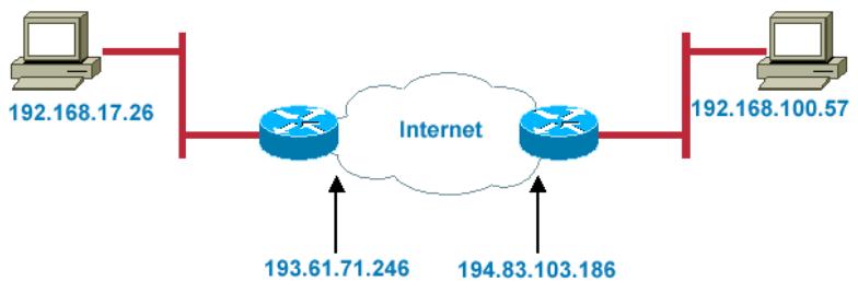
| IP | AH/E | IP | TC | Dat |
Transport Mode
- This mode is used to provide data security between two networks. It provides protection for the entire IP packet and is sent by adding an outer IP header corresponding to the two tunnel end-points. Since tunnel mode hides the original IP header, it provides security of the networks with private IP address space.
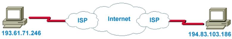
| IP | AH/E | TC | Dat |
E.2.3 Tunnel Mode AH
AH is typically applied to a data packet in the following manner:
Original Packet
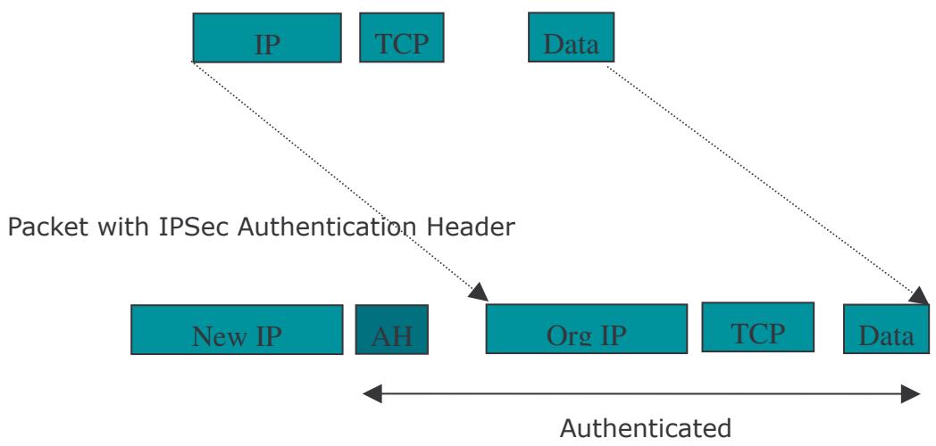
E.2.4 Tunnel Mode ESP
Here is an example of a packet with ESP applied:
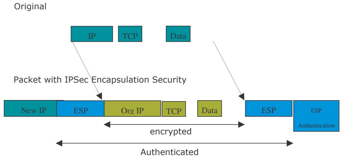
E.2.5 Internet Key Exchange (IKE)
Before either AH or ESP can be used, it is necessary for the two communication devices to exchange a secret key that the security protocols themselves will use. To do this, IPSec uses Internet Key Exchange (IKE) as a primary support protocol. IKE facilitates and automates the SA setup, and exchanges keys between parties transferring data. Using keys ensures that only the sender and receiver of a message can access it. These keys need to be re-created or refreshed frequently so that the parties can communicate securely with each other. Refreshing keys on a regular basis ensures data confidentiality.
There are two phases to this process. Phase I deals with the negotiation and management of IKE and IPSec parameters. This phase can be carried out in either one of two modes: Main Mode or Aggressive Mode. Main mode utilizes three message pairs that negotiate IKE parameters, establish a shared secret and derive session keys, and exchange and provide identities, retroactively authenticating the information sent. This method is very secure, but when using the pre-shared key method for authentication, it is possible to use IDs other than the packets's IP addresses. Aggressive mode reduces this process to three messages, but parameter negotiation is limited, identity protection is lacking except when using public key encryption, and is more vulnerable to Denial of Service attacks.
Phase II, known as Quick Mode, establishes symmetrical IPSec Security Associations for both AH and ESP. It does this by negotiating IPSec parameters, exchange nonces to derive session keys from the IKE shared secret, exchange DH values to
generate a new key, and identify which traffic this SA bundle will protect using selectors (IDi and IDr payloads).
The following is an illustration on how data is handled with IKE:
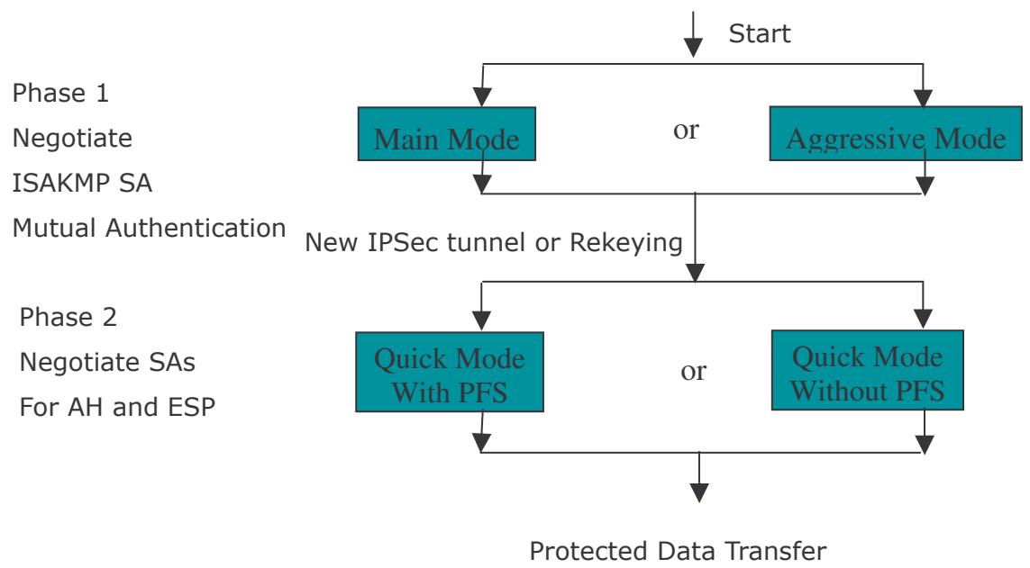
Appendix F: IPSec Logs and Events
F.1 IPSec Log Event Categories
There are three major categories of IPSec Log Events for your RF30. These include:
- IKE Negotiate Packet Messages
- Rejected IKE Messages
- IKE Negotiated Status Messages
The table in the following section lists the different events of each category, and provides a detailed explanation of each.
F.2 IPSec Log Event Table
| IKE Negotiate Packet Messages | |
| Log Event | Explanation |
| Send Main mode initial message of ISAKMP | Sending the first initial message of main mode (phase I). Done to exchange encryption algorithm, hash algorithm, and authentication method. |
| Send Aggressive mode initial message of ISAKMP | Sending the first message of aggressive mode (phase I). |
| Received Main mode initial message of ISAKMP | Received the first message of main mode. |
| Send Main mode first response message of ISAKMP | Sending the first response message of main mode. Done to exchange encryption algorithm, hash algorithm, and authentication method. |
| Received Main mode first response message of ISAKMP | Received the first response message of main mode. Done to exchange encryption algorithm, hash algorithm, and authentication method. |
| Send Main mode second message of ISAKMP | Sending the second message of main mode. Done to exchange key values. |
| Received Main mode second message of ISAKMP | Received the second message of main mode. Done to exchange key values. |
| Send Main mode second response message of ISAKMP | Sending the main mode second response message. Done to exchange key values. |
| Received Main mode second response message of ISAKMP | Received the main mode second response message. Done to exchange key values. |
| Send Main mode third message of ISAKMP | Sending the third message of main mode. Done for authentication. |
| Received Main mode third message of ISAKMP | Received the third message of main mode. Done for authentication. |
| Send Main mode third response message of ISAKMP | Sending the third response message of main mode. Done for authentication. |
| Received Main mode third message of ISAKMP | Received the third response message of main mode. Done for authentication. |
| response message of ISAKMP | authentication. |
| Received Aggressive mode initial ISAKMP Message | Received the first message of aggressive mode. |
| Send Aggressive mode first response message of ISAKMP | Sending the first response message of aggressive mode. Done to exchange proposal and key values. |
| Received Aggressive mode first response message of ISAKMP | Received the first response message of aggressive mode. Done to exchange proposal and key values. |
| Send Aggressive mode second message of ISAKMP | Sending the second message of aggressive mode. Done to exchange proposal and key values. |
| Received Aggressive mode second ISAKP Message | Received the second message of aggressive mode. Done to exchange proposal and key values. |
| Send Quick mode initial message | Sending the first message of quick mode (Phase II). Done to exchange proposal and key values (IPSec). |
| Received Quick mode initial message | Received the first message of quick mode (Phase II). Done to exchange proposal and key values (IPSec). |
| Send Quick mode first response message | Sending the first response message of quick mode (Phase II). Done to exchange proposal and key values (IPSec). |
| Received Quick mode first response message | Received the first response message of quick mode (Phase II). Done to exchange proposal and key values (IPSec). |
| Send Quick mode second message | Sending the second message of quick mode (Phase II). |
| Received Quick mode second message | Received the second message of quick mode (Phase II). |
| ISAKMP IKE Packet | Indicates IKE packet. |
| ISAKMP Information | Indicates Information packet. |
| ISAKMP Quick Mode | Indicates quick mode packet. |
| Rejected IKE Messages | |
| NO PROPOSAL CHOSEN: No acceptable Oakley Transform | |
| NO PROPOSAL CHOSEN: No acceptable Proposal in IPsec SA | |
| NO PROPOSAL CHOSEN: PFS is required in Quick Initial SA. | |
| NO PROPOSAL CHOSEN: PFS is not required in Quick Initial SA. | |
| NO PROPOSAL CHOSEN: Initial Aggressive Mode message from %s but no connection has been configured | |
| NO PROPOSAL CHOSEN: Initial Main Mode message received on %s:%u but no connection has been authorized | |
| INVALID ID: Require peer to have ID %s, but peer declares %s | |
| INVALID ID INFORMATION: Initial Aggressive Mode packet claiming to be from %s on %s but no connection has been authorized | |
| INVALID ID: Require peer to have ID %s, but peer declares %s | |
| INVALID ID INFORMATION: Initial Aggressive Mode packet claiming to be from %s on %s but no connection has been authorized | |
| IKE Negotiated Status Messages | |
| Received Delete SA payload and deleting IPSEC State (integer) | |
| Received Delete SA payload: Deleting ISAKMP State (integer) | |
| (Main/Aggressive) mode peer ID is (identifier string) | |
| ISAKMP SA Established | |
| IPsec SA Established | |
Appendix G: Bandwidth Management with QoS
G.1 Overview
In a home or office environment, users constantly have to transmit data to and from the Internet. When too many are accessing the Internet at the same time, service can slow to a crawl, causing service interruptions and general frustration. Quality of Service (QoS) is one of the ways the RF30 can optimize the use of bandwidth, ensuring a smooth and responsive Internet connection for all users.
G.2 What is Quality of Service?
QoS is a feature that prioritizes and guarantees bandwidth to achieve optimal service performance. QoS can maximize the use of available network bandwidth by prioritizing time-sensitive traffic to avoid latencies and delays. By ensuring that time-sensitive applications such as VoIP and streaming video get priority access to bandwidth, users in both home and office environments can enjoy smooth and responsive data transmission no matter which applications they are running.
If you've ever experienced slow Internet speeds due to other network users using bandwidth-consuming applications like P2P, you'll understand why QoS is such a breakthrough for home users and office users. Cometlabs makes itself unique by integrating QoS in its routers for both inbound and outbound traffic.
QoS helps users manage bandwidth and effectively prioritize data traffic. It gives you full control over the traffic of any type of data. Employed on DiffServ (Differentiated Services) architecture, data traffic is given priority by the router; ensuring latency-sensitive applications like voice and mission-critical data such as VPN move through the router at lightning speeds, even under heavy load. You can throttle the speed of different types of data passing through the router, limit the speed of unimportant or bandwidth-consuming applications, and even distribute the bandwidth for different
groups of users at home or in the office. QoS keeps your Internet connection smooth and responsive.
G.3 How Does QoS Work?
QoS employs three different methods for optimizing bandwidth:
-Prioritization: Assigns different priority levels for different applications, prioritizing traffic. High, Normal and Low priority settings.
-Outbound and Inbound IP Throttling: Controls network traffic and allows you to limit the speed of each application.
- DiffServ Technology: Manages priority queues and DSCP tagging through the Internet backbone. Manages traffic among Ethernet, wireless, and ADSL interfaces.
G.4 Who Needs QoS?
QoS is ideal for home and office users who need to use a variety of real-time applications like VoIP, on-line games, P2P, video streaming, and FTP simultaneously. With QoS, you can optimize your bandwidth to accommodate several of these applications without experiencing latency or service interruptions.
G.4.1 Home Users
Low latency is everything for gamers. Most home users feel frustrated when trying to play an online game over a shared ADSL connection. Unfortunately, most routers have no way of determining the importance of the packet at any given time. All the traffic is treated equally, so a packet containing an "urgent" command may be delayed. QoS gives you the ability to control the bandwidth. Using IP Throttling, bandwidth limits can be enforced on a particular application or any system within the LAN. Prioritization specifies which packets have priority and should not be delayed, and which packets have lower priority and should be moved to the end of the upload queue.
Suppose there are four students sharing a three-floor house with one single broadband connection. Tom, a college freshman, is playing the online game with his group members, while Mary, a sophomore student, is talking to her net pal via Skype. Meanwhile, Jacky is downloading a movie file by using the P2P application program. Sophia, however, is just trying to log on to the website to send her photos to her family. As a result, the net speed slows to a crawl and affects everyone sharing the
Internet connection. QoS is designed for managing traffic flow and bandwidth to solve this problem. You can first classify different applications (online games, FTP, Skype, email) as shown in the table below. Then, you can manage and prioritize the flow of bandwidth at different levels (e.g. 30% for games, 20% for downloads, 10% for email, 20% for FTP, and 35% for others). QoS can be used to identify different applications and assign priority to enable a smooth and responsive broadband connection.
| Application | Data Ratio (%) | Priority |
| On-line games | 30% | High |
| Skype | 5% | High |
| 10% | High | |
| FTP | 20% | Upload (High), Download (Normal) |
| Other | 35% |
G.4.2 Office Users
QoS is also ideal for small businesses using an office server as a web server. With QoS control, web pages served to your customers can be given top priority and delivered first so that it will not be impeded by email and office web browsing.
Here is a good example of how QoS can work in an office environment. A CEO is holding a videoconference with international clients in the meeting room. However, the streaming video and voice frequently lag. Sales people are talking to international agencies via VoIP phone, while sending orders via email to vendors for production. However, some staff are downloading MP3 music files, large-size photos and watching video streaming online. Consequently, the Internet connection slows down. This is why business users need QoS to manage data traffic. With QoS, the network administrator can define and classify important packets; specify a minimum guaranteed rate for each application, and ensure that important packets have priority to ensure a good quality of broadband connection for the entire organization.
| Application | Data Ratio (%) | Priority |
| Videoconferencing | 30% | High |
| VoIP | 20% | High |
| 10% | High | |
| FTP | 10% | Upload (High), Download (Normal) |
| Other | 30% | MP3 (Low), MSN (Normal) |
Appendix H: Router Setup Examples
H.1 Outbound Fail Over
Step 1: Go to Configuration > WAN > ISP Settings. Select WAN1 and WAN2 and click Edit.
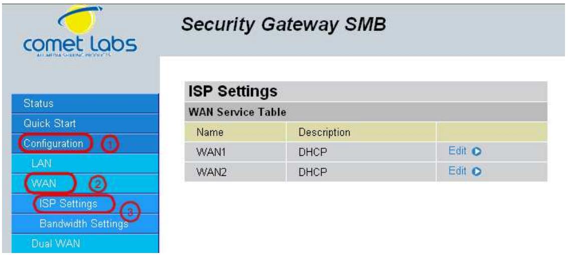
Step 2: Configure WAN1 and WAN2 according to the information given by your ISP.
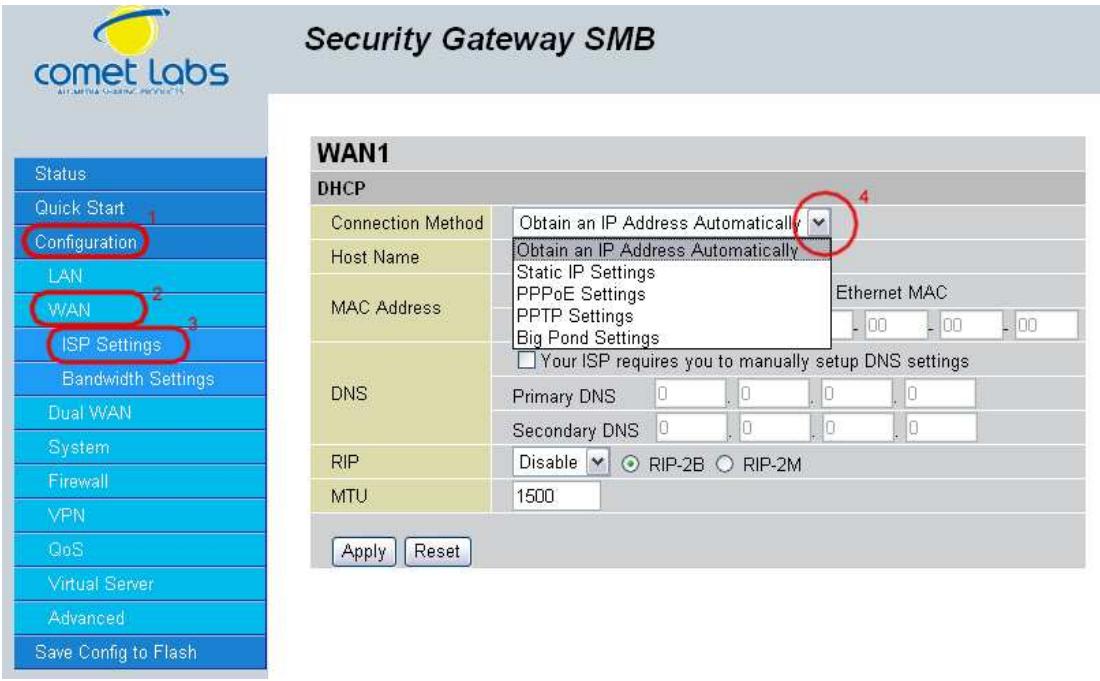
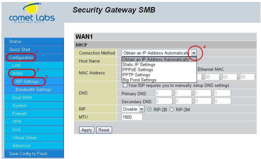
Step 3: Go to Configuration > Dual WAN > General Settings. Select the Fail Over radio button. Under Connectivity Decision, input the number of times the RF30 should probe the WAN before deciding that the ISP is in service or not (3 by default). Next, input the duration of the probe cycle (30 sec. by default) and choose the way WAN ports are probed.
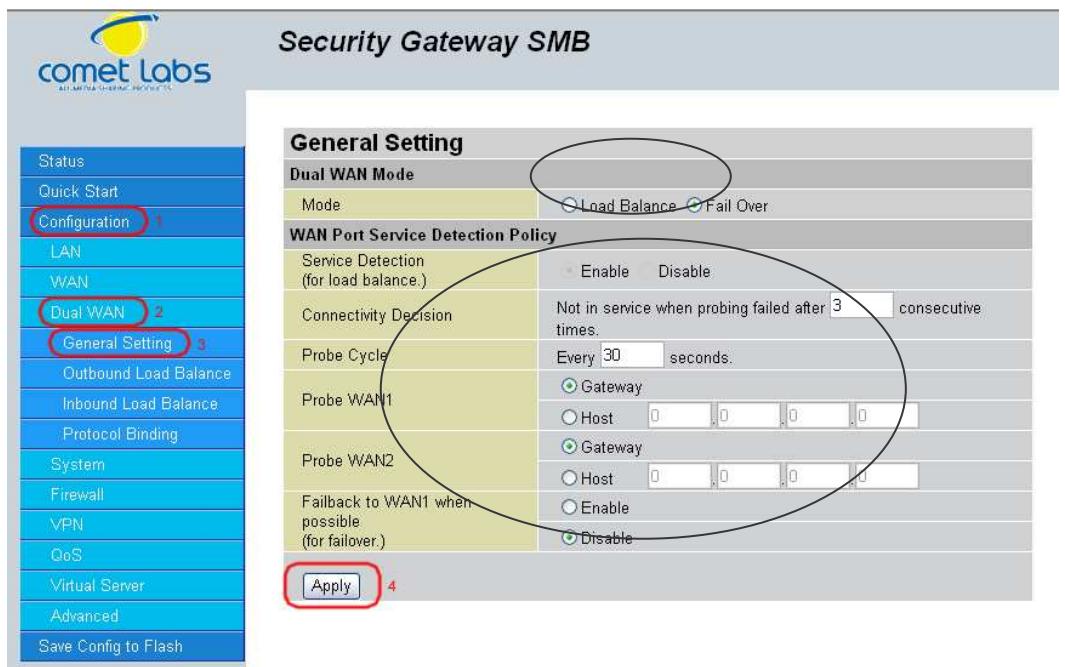
Please ensure the WAN ports are functioning by performing a ping operation on each before proceeding. Finally, choose whether or not the RF30 should fail back to WAN1.
Step 4: Click Save Config to save all changes to flash memory.
H.2 Outbound Load Balancing
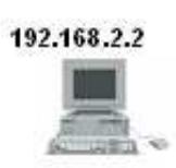
192.168.2.3
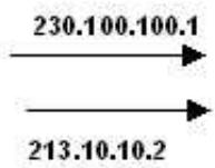
ISP
Internet
With Outbound Load Balancing, you can improve upload performance by optimizing your connection via Dual WAN. To do this, follow these steps:
Step 1: Go to Configuration > WAN > ISP Settings. Configure your WAN1 ISP settings and click Apply.
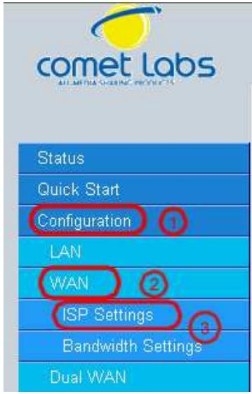
Security Gateway SMB
| ISP Settings | ||
| WAN Service Table | ||
| Name | Description | |
| WAN1 | DHCP | Edit |
| WAN2 | DHCP | Edit |
Step 2: Configure your WAN2 ISP settings and click Apply.
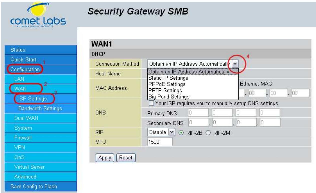
Step 3: Go to Configuration > Dual WAN > General Settings. Select the Load Balance radio button.
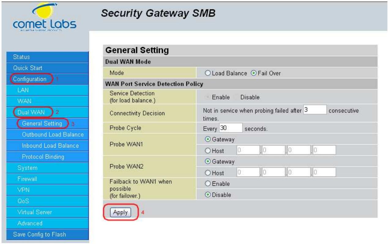
Step 4: Go to Configuration > Dual WAN > Outbound Load Balance. Choose the Load Balance mechanism you want and click Apply.
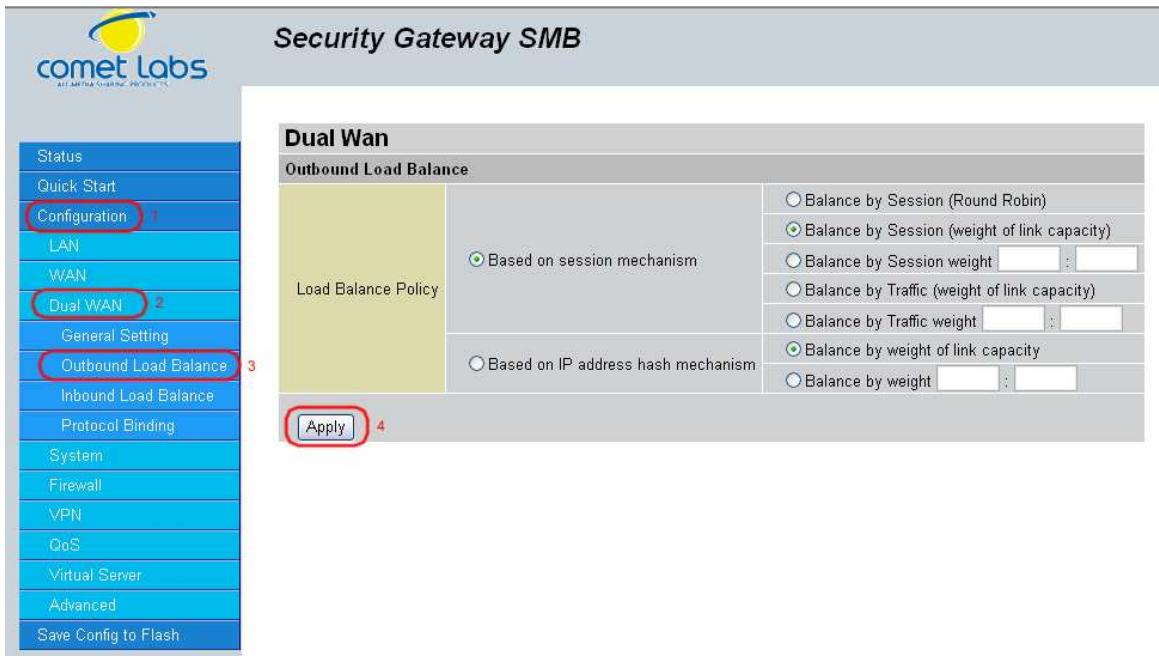
Step 5: Complete. To check traffic statistics, go to Status > Traffic Statistics.
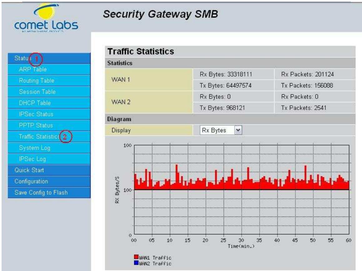
Step 6: Click Save Config to save all changes to flash memory.
H.3 Inbound Fail Over
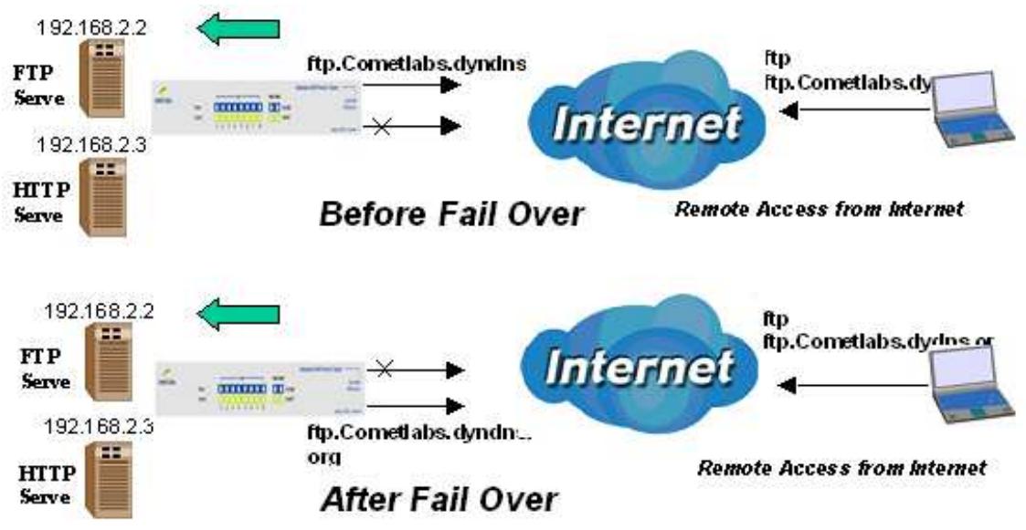
Configuring your RF30 for Inbound Fail Over is a great way to ensure a more reliable connection for incoming requests. To do so, follow these steps:
NOTE: Before you begin, ensure that both WAN1 and WAN2 have been properly configured. See Chapter 4: Router Configuration for more details.
Step 1: From the Web Configuration Interface, go to Configuration > Dual WAN > General Settings. Select the Fail Over radio button.

Step 2: Configure Fail Over options if necessary.
Step 3: Go to Configuration > Advanced > Dynamic DNS. Set the WAN1 DDNS settings.

Step 4: From the same menu, set the WAN2 DDNS settings.
Step 5: Click Save Config to save all changes to flash memory.
H.4 DNS Inbound Fail Over

NOTE: Before proceeding, please ensure that both WAN1 and WAN2 are properly configured according to the settings provided by your ISP. If not, please refer to Chapter 4.2.2.1 ISP Settings for details on how to configure your WAN ports.
Step 1: Go to Configuration > Dual WAN > General Settings. Select the Fail Over radio button and configure your fail over policy.

Step 2: Go to Configuration > Dual WAN > Inbound Load Balance. Select the Enable radio button and configure DNS Server 1 by clicking Edit.
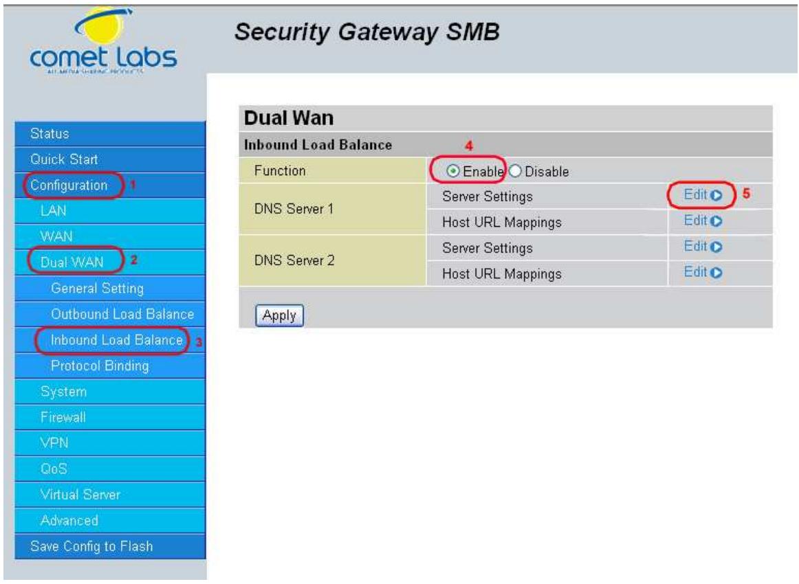
Step 3: Input DNS Server 1 settings and click Apply.
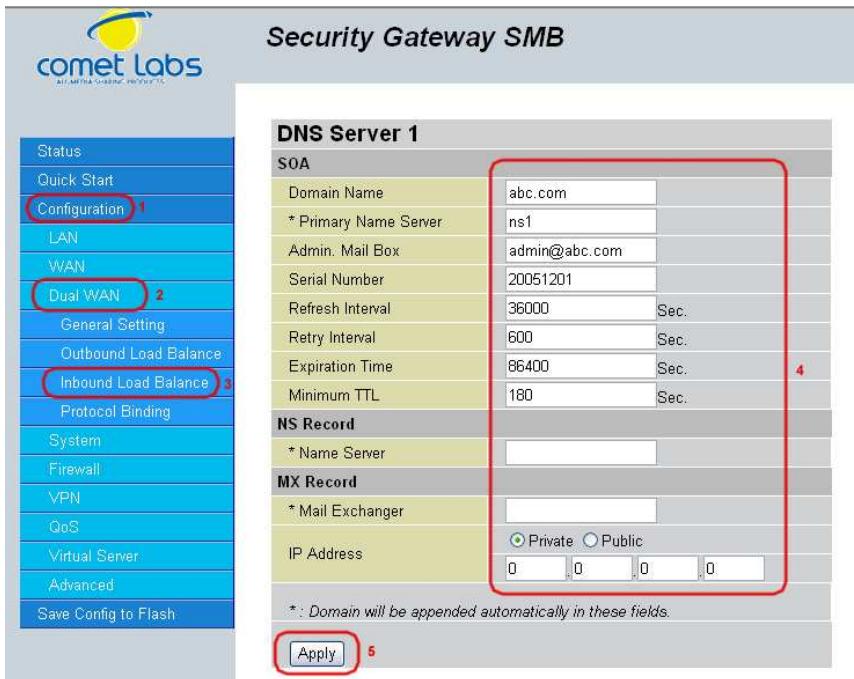
Step 4: Configure your Host URL Mapping for DNS Server 1 by clicking Edit to enter the Host URL Mappings List. Click Create and input the settings for Host URL Mappings and click New.
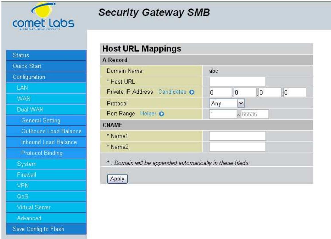
Step 5: Click Save Config to save all changes to flash memory.
H.5 DNS Inbound Load Balancing
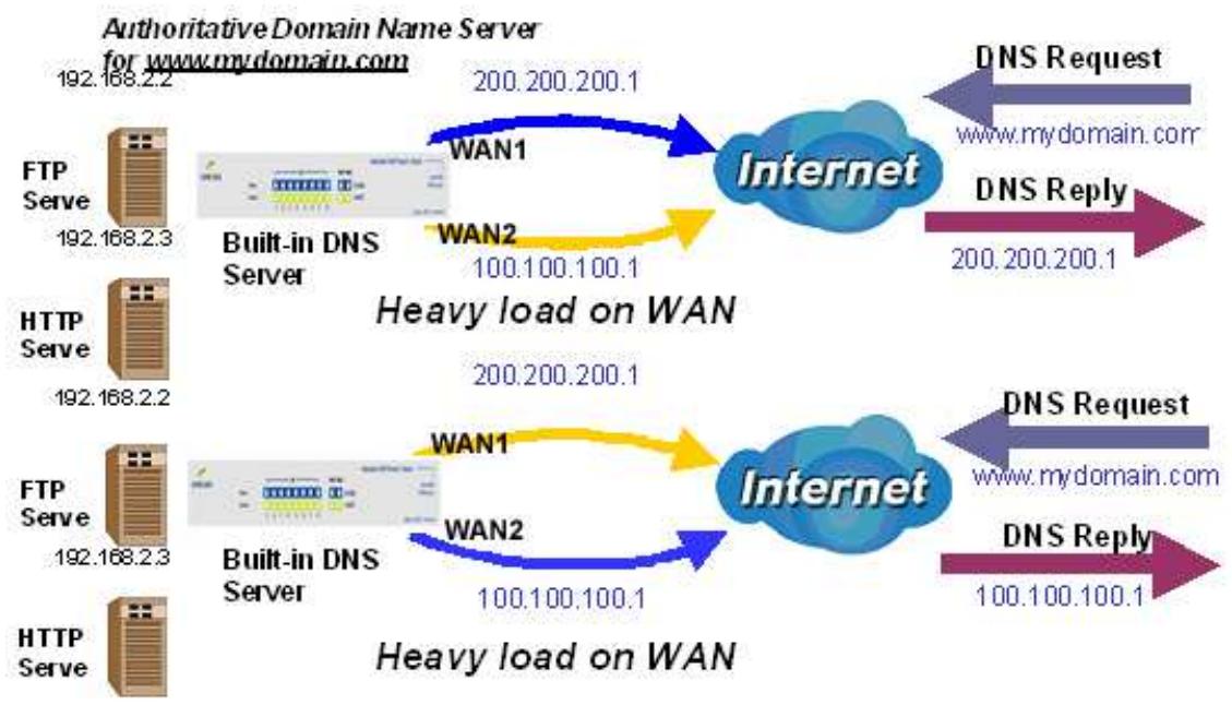
Step 1: Go to Configuration > Dual WAN > General Settings. Select the Load Balance radio button.
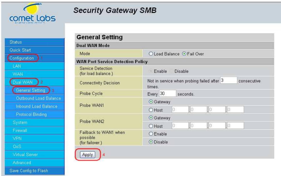
Step 2: Go to Configuration > Dual WAN > Inbound Load Balance > Server Settings and configure DNS Server 1.
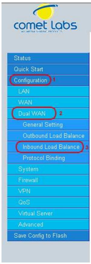
Security Gateway SMB
DNS Server 1
soA
Domain Name
*Primary Name Server
Admin. Mail Box
Serial Number
Refresh Interva
Retry Interval
Expiration Time
Minimum TTL
NS Record
*NameServer
MX Record
- Mail Exchanger
IP Address
*: Domain will be appended automatically in these fields.
Apply
Step 3: Go to Configuration > Dual WAN > Inbound Load Balance > Host URL Mapping and configure your FTP mapping.
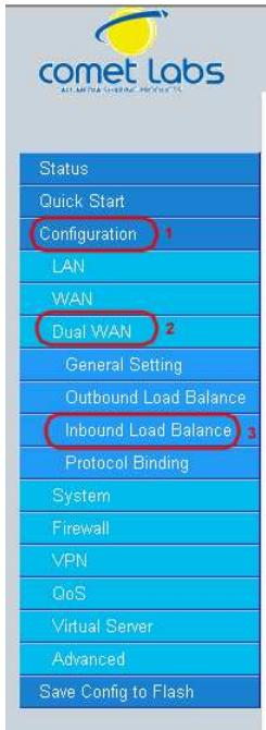
Security Gateway SMB
Dual Wan
Inbound Load Balance
Function
DNS Server 1
DNS Server 2
Apply
Enable Disable
Server Settings
Host URL Mappings
Server Settings
Host URL Mappings
Edit
Edit
Edit O
Edit
Step 4: Next configure your HTTP mapping.
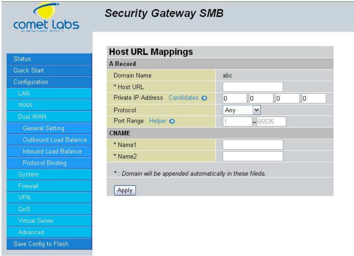
Step 5: Click Save Config to save all changes to flash memory.
H.6 Dynamic DNS Inbound Load Balancing
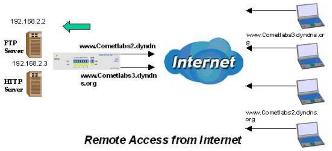
Step 1: Go to Configuration > WAN > Bandwidth Settings. Configure your WAN inbound and outbound bandwidth.
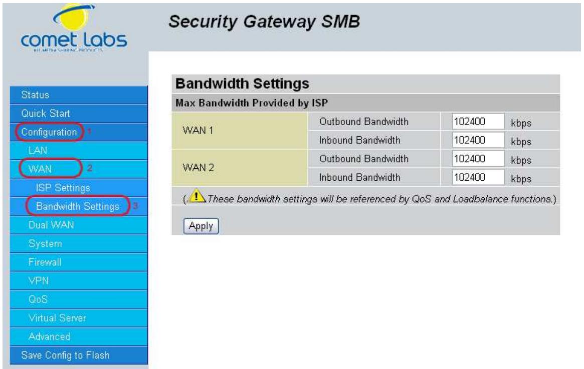
Step 2: Go to Configuration > Dual WAN > General Settings and enable Load Balance mode. You may then decide whether to enable Service Detection or not.

Step 3: Go to Configuration > Dual WAN > Outbound Load Balance. Choose your load balance policy and click Apply to apply your changes. If you selected Based on session mechanism as your policy, the source IP address and destination IP address may go through WAN1 or WAN2 depending on policy settings. If you selected Based on IP hash mechanism as your policy, the source IP address and destination IP address will go through a specific WAN port according to the IP hash algorithm.
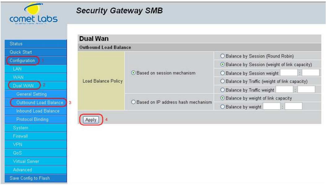
Step 4: Go to Configuration > Advanced > Dynamic DNS and input the dynamic DNS settings for WAN1 and WAN2.
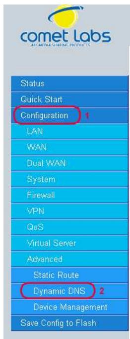
Security Gateway SMB
Dynamic DNS
| Dynamic DNS Settings | |||
| Parameters | |||
| Dynamic DNS | Disable | 6 | |
| Dynamic DNS Server | www.dyndns.org (dynamic) | ||
| Wildcard | Disable | 8 | |
| Domain Name | maccompagnie.dyndns.org | ||
| Username | monnom | ||
| Password | ********** | ||
WAN1:
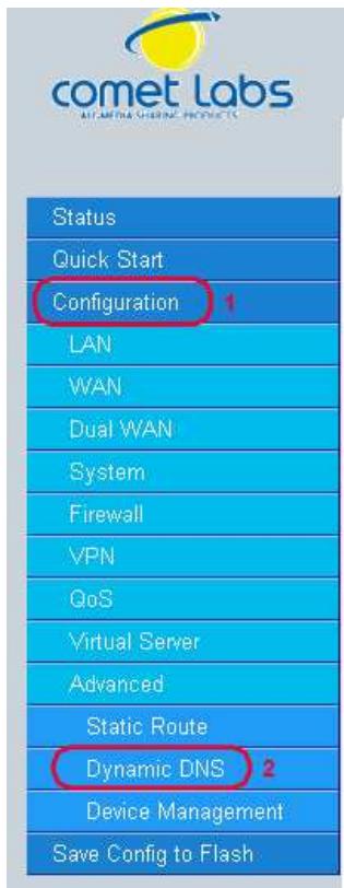
Security Gateway SMB
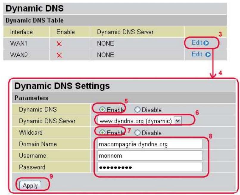
WAN 2:
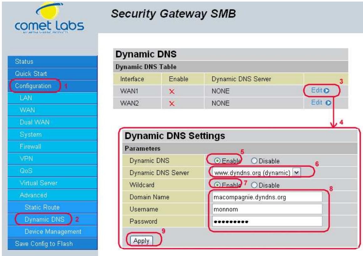
Step 5: Go to Configuration > Virtual Server and set up a virtual server for both FTP and HTTP.
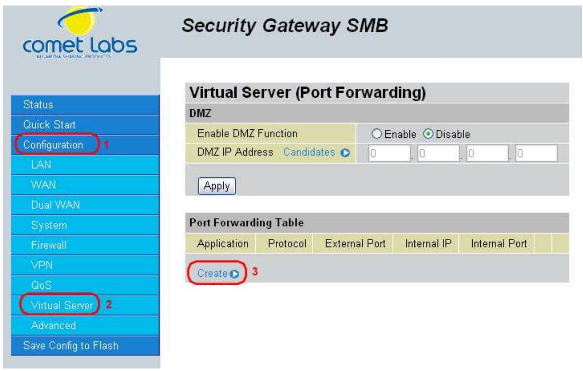
Security Gateway SMB
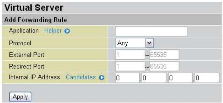
Step 6: Click Save Config to save all changes to flash memory.
H.7 VPN Configuration
This section outlines some concrete examples on how you can configure the RF30 for your VPN.
H.7.1 LAN to LAN
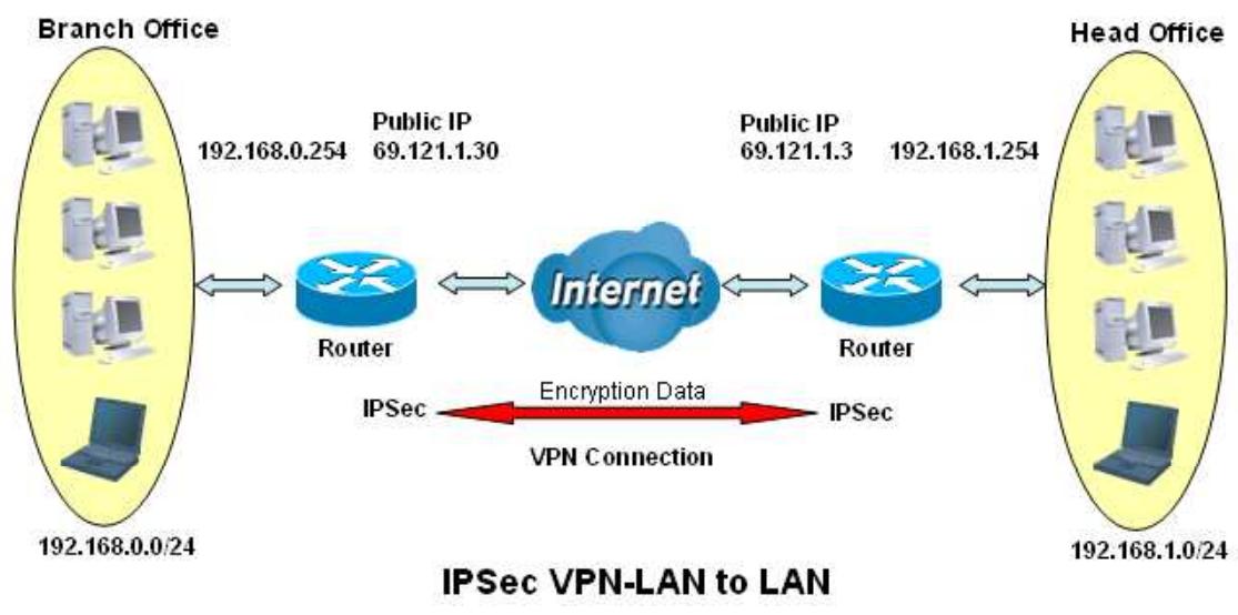
| Branch Office | Head Office | |
| Local | ||
| ID | IP Address | IP Address |
| Data | 69.121.1.30 | 69.121.1.3 |
| Network | Any Local Address | Any Local Address |
| IP Address | 192.168.0.0 | 192.168.1.0 |
| Netmask | 255.255.255.0 | 255.255.255.0 |
| Remote | ||
| Secure Gateway Address(or Hostname) | 69.121.1.3 | 69.121.1.30 |
| ID | IP Address | IP Address |
| Data | 69.121.1.3 | 69.121.1.30 |
| Network | Subnet | Subnet |
| IP Address | 192.168.1.0 | 192.168.0.0 |
| Netmask | 255.255.255.0 | 255.255.255.0 |
| Proposal | ||
| IKE Pre-shared Key | 12345678 | 12345678 |
| Security Algorithm | Main Mode; ESP: MD5 3DES PFS | Main ESP MD5 3DES PFS |
H.7.2 Host to LAN
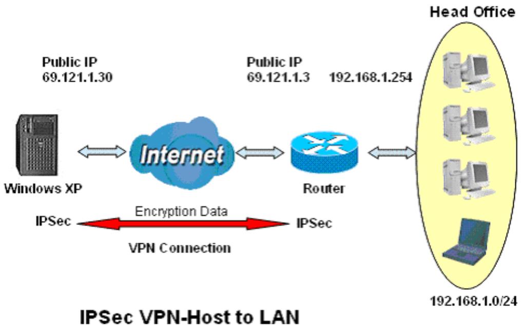
| Single client | Head Office | |
| Local | ||
| ID | IP Address | IP Address |
| Data | 69.121.1.30 | 69.121.1.3 |
| Network | Any Local Address | Any Local Address |
| IP Address | 0.0.0.0 | 192.168.1.0 |
| Netmask | 0.0.0.0 | 255.255.255.0 |
| Remote | ||
| Secure Gateway Address(or Hostname) | 69.121.1.3 | 69.121.1.30 |
| ID | IP Address | IP Address |
| Data | 69.121.1.3 | 69.121.1.30 |
| Network | Subnet | Single Address |
| IP Address | 192.168.1.0 | 69.121.1.30 |
| Netmask | 255.255.255.0 | 255.255.255.255 |
| Proposal | ||
| IKE Pre-shared Key | 12345678 | 12345678 |
| Security Algorithm | Main Mode; ESP: MD5 3DES PFS | Main ESP MD5 3DES PFS |
H.8 IP Sec Fail Over (Gateway to Gateway)
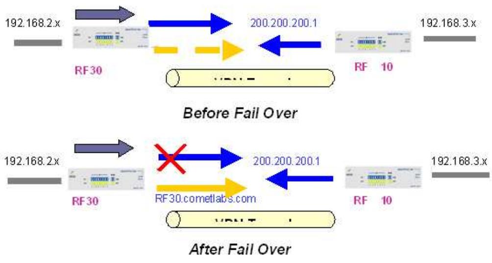
Step 1: Go to Configuration > Dual WAN > General Settings. Enable Fail Over by selecting the Fail Over radio button. Then, configure your Fail Over policy.

Step 2: Go to Configuration > Advanced > Dynamic DNS and configure your dynamic DNS settings (Both WAN1 and WAN2).
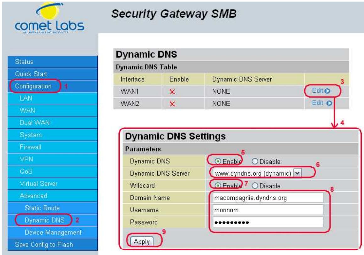
Step 3: Go to Configuration > VPN > IPSec > IPSec Policy. Click Create to configure VPN settings.
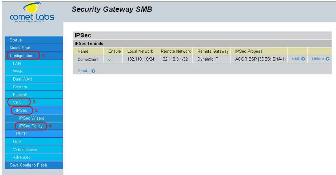
Step 4: Click Save Config to save all changes to flash memory.
To configure the RF30 10 gateway, refer to the screenshot below.
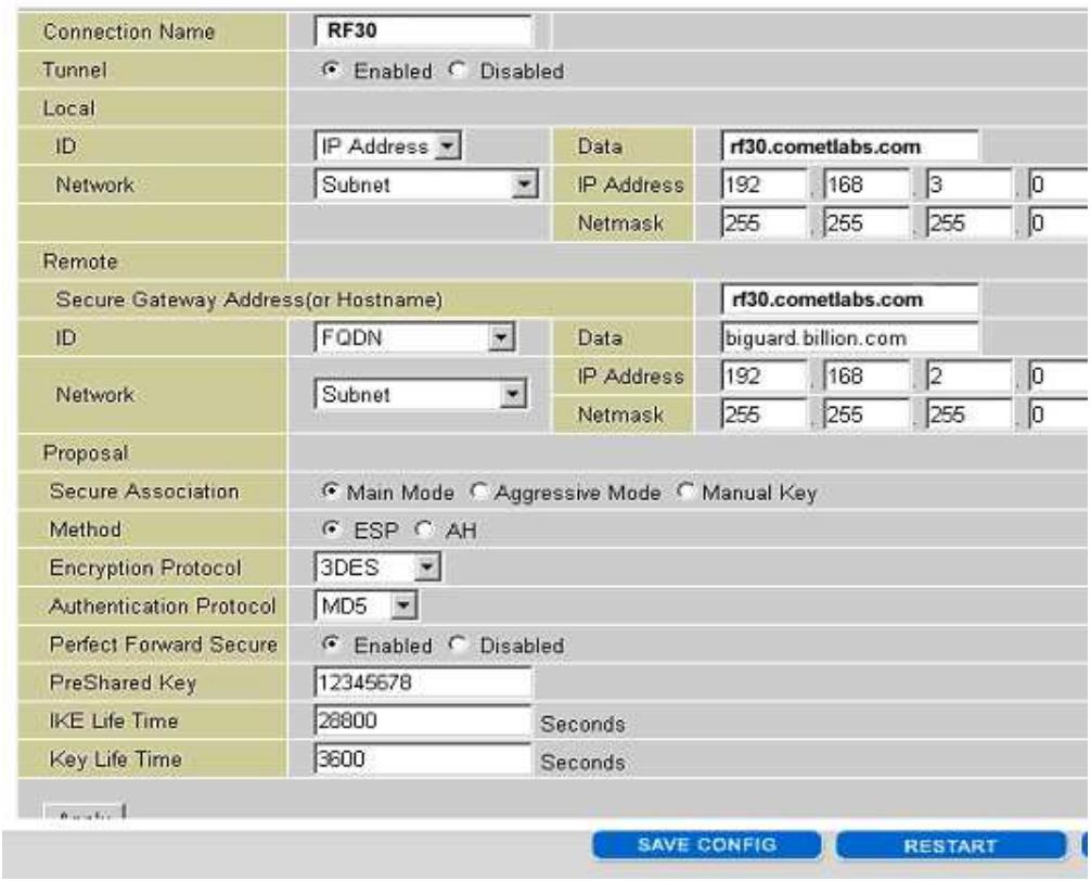
H.9 VPN Concentrator
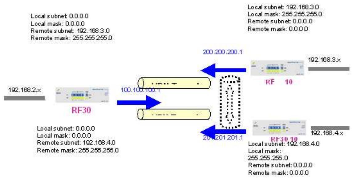
Step 1: Go to Configuration > VPN > IPSec > IPSec Policy and configure the link from RF 30 to RF 10 Branch A.
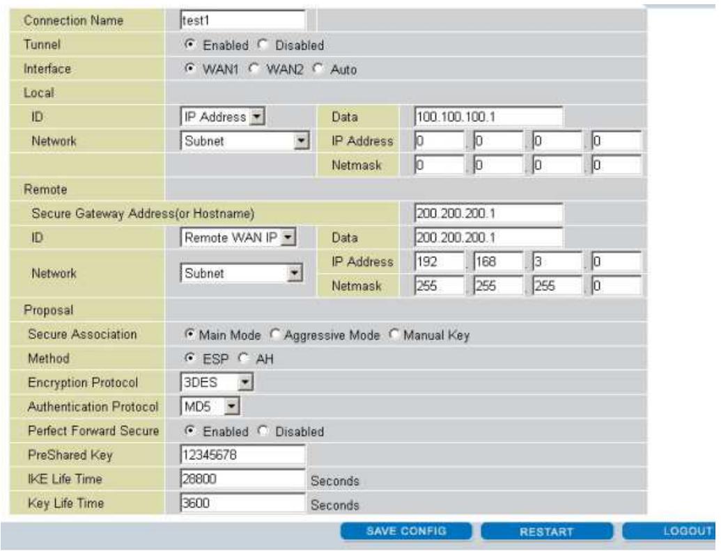
Step 2: Go to Configuration > VPN > IPSec > IPSec Policy and configure the link from RF 30 to RF 10 Branch B.
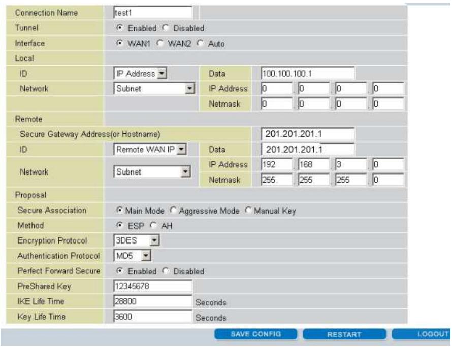
Step 3: Go to Configuration > VPN > IPSec > IPSec Policy and configure the connection from RF 10 Branch A to RF 30.
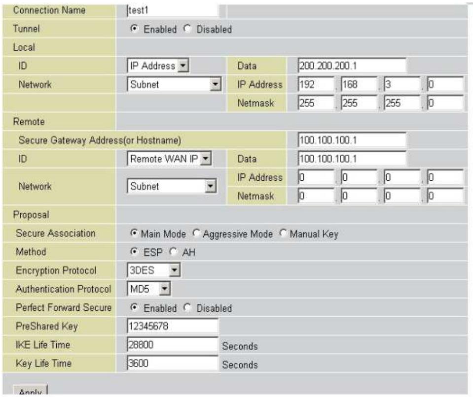
Step 4: Go to Configuration > VPN > IPSec > IPSec Policy and configure the connection from RF 10 Branch B to RF 30.
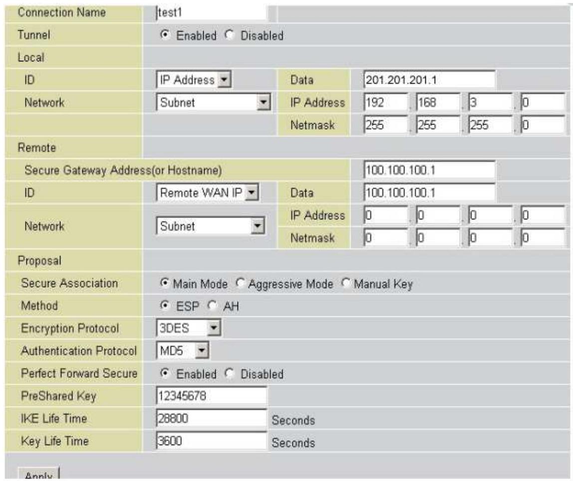
Step 5: Click Save Config to save all changes to flash memory.
H.10 Protocol Binding
Step 1: Go to Configuration > Dual WAN > General Settings. Select the Load Balancing radio button.
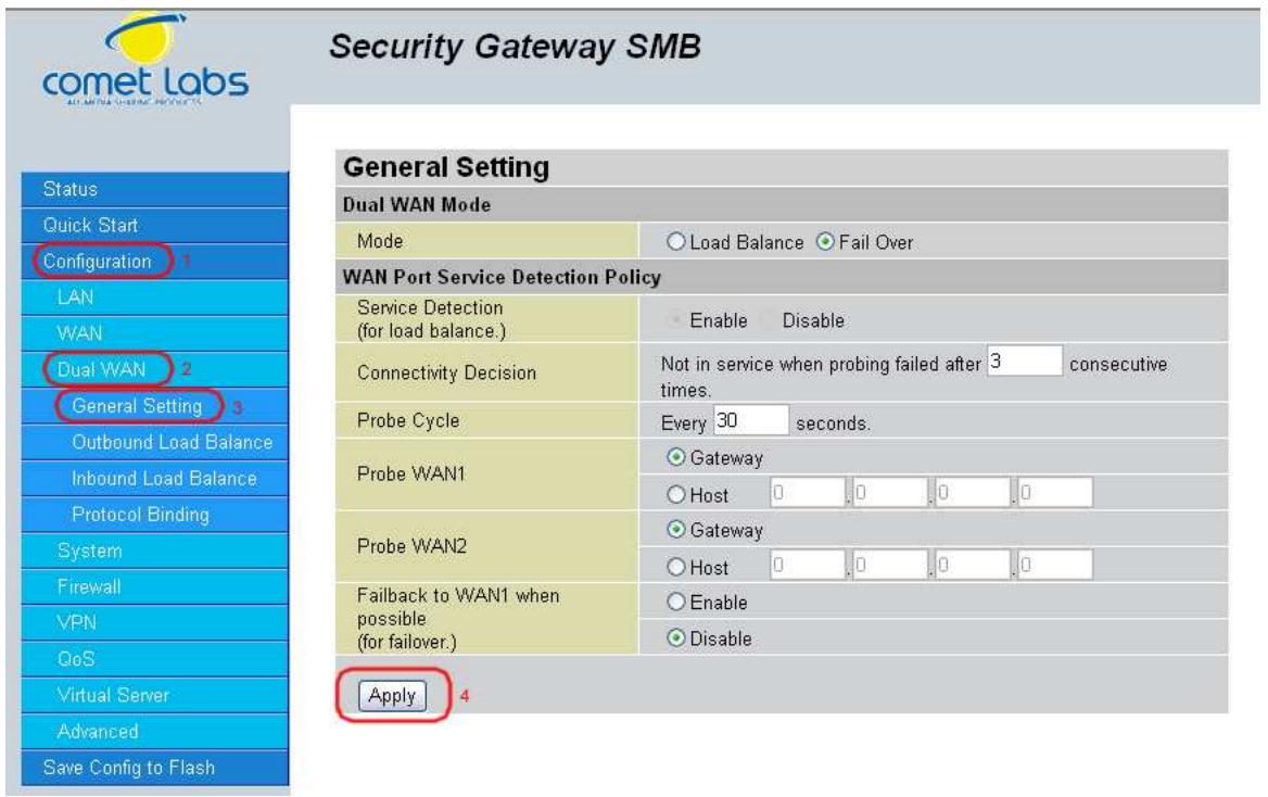
Step 2: Go to Configuration > Dual WAN > Protocol Binding and configure settings for WAN1.
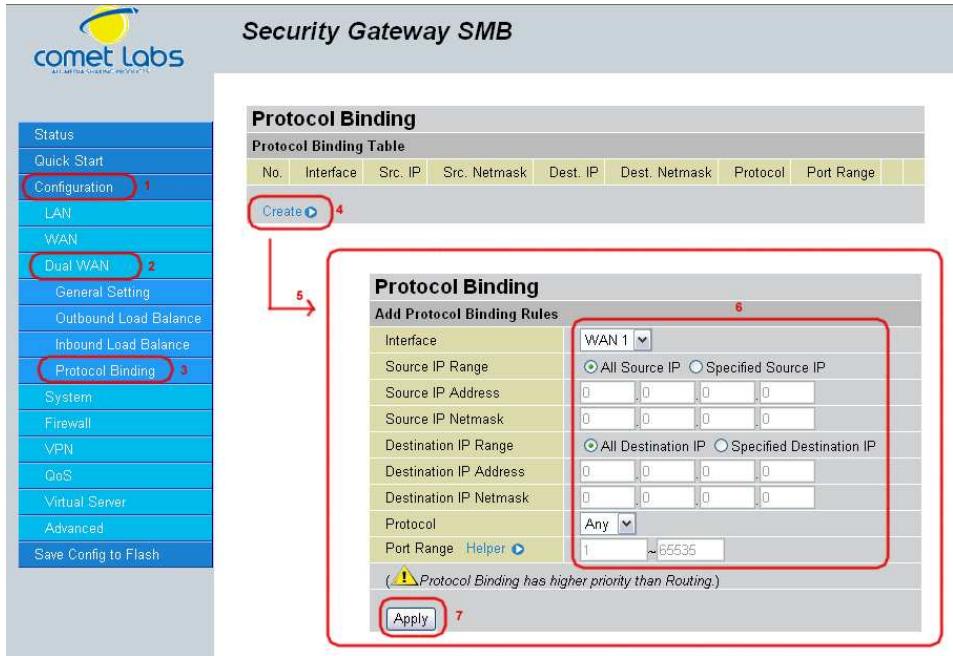
Step 3: Go to Configuration > Dual WAN > Protocol Binding and configure settings for WAN2.
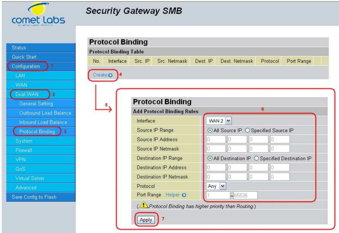
Step 4: Click Save Config to save all changes to flash memory.