XA 4000 - Power amplifier DYNACORD - Free user manual and instructions
Find the device manual for free XA 4000 DYNACORD in PDF.

| Product type | Two-way power amplifier |
| Technology | Class-H with SWITCHMODE PRECISION switching power supply |
| Output power (SUB) | 1100 W at 4 Ω |
| Output power (TOP) | 900 W at 4 Ω |
| Crossover frequency | 140 Hz, modified Butterworth filter 18 dB/octave |
| Input connectors | Electronically balanced female XLR |
| Output connectors | SPEAKON (SYSTEM 4-pole, separate SUB, TOP) |
| Level controls | Detented SUB and TOP potentiometers from +6 dB to -∞ |
| Integrated functions | High-pass filter (Locomut), LPN (Low Pass Notch) equalization |
| Cooling | Front to rear, two 3-speed fans (off/slow/fast) |
| Protection | Thermal and electrical overload, short-circuit, HF/DC, Back-EMF, current limiter, startup delay |
| Mains power supply | 230 V (adaptable 100-240 V) – see consumption table |
| Consumption (idle) | 80 W |
| Consumption (1/8 max power @ 4 Ω) | 610 W |
| Dimensions (W x H x D) | 19 inches (48.3 cm) wide, 2U (8.9 cm) high, approximately 44 cm deep |
| Weight | Approximately 20 kg |
| Maximum ambient temperature | 40 °C |
| Maintenance and cleaning | Clean with a dry cloth, do not block ventilation slots |
| Safety | Complies with EN 60065, use the supplied mains cord, do not open |
| Warranty | Warranty certificate provided, keep the invoice |
Frequently Asked Questions - XA 4000 DYNACORD
User questions about XA 4000 DYNACORD
0 question about this device. Answer the ones you know or ask your own.
Ask a new question about this device
Download the instructions for your Power amplifier in PDF format for free! Find your manual XA 4000 - DYNACORD and take your electronic device back in hand. On this page are published all the documents necessary for the use of your device. XA 4000 by DYNACORD.
USER MANUAL XA 4000 DYNACORD
IMPORTANT SAFETY INSTRUCTIONS 3
IMPORTANT SERVICE INSTRUCTIONS 3
DESCRIPTION 4
UNPACKING & WARRANTY 5
INSTALLATION NOTES 5
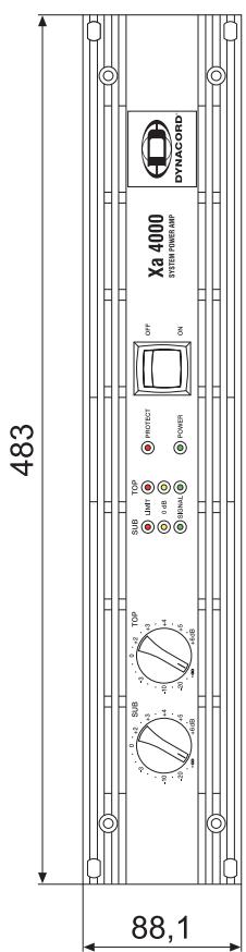
FRONT VIEW 6
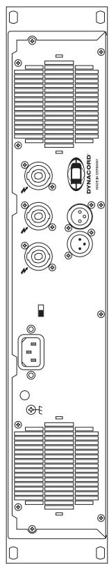
REAR PANEL 7
INPUT 7
POWERAMPOUTPUT 8
GROUND-LIFT SWITCH 8
MAINS INPUT 8
NOTES ON ADJUSTMENTS 10
GENERAL INSTALLATION NOTES 11
EXAMPLES FOR ACTIVE 2-WAY APPLICATIONS 12
SPECIFICATIONS/TECHNISCHE DATEN 42
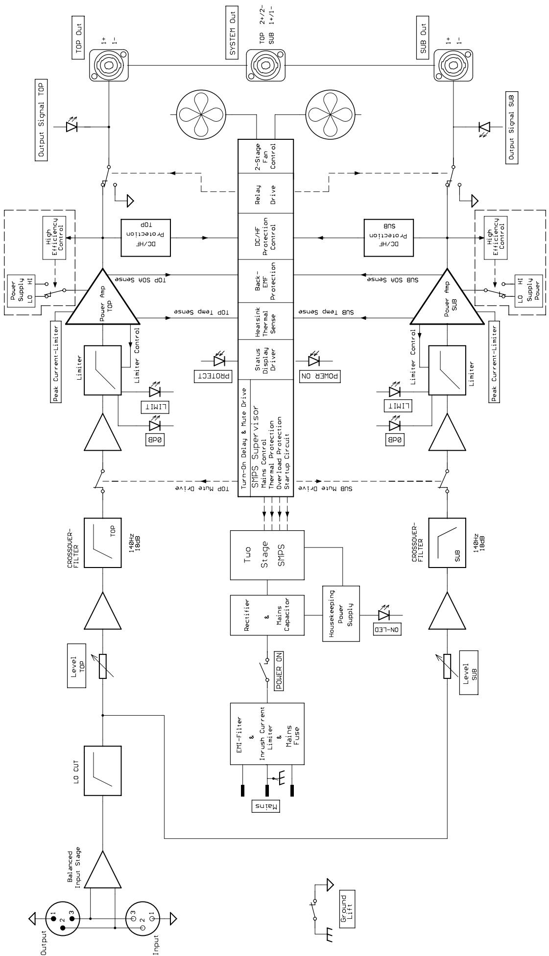
BLOCKDIAGRAM 43
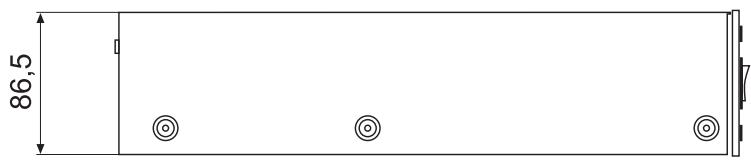
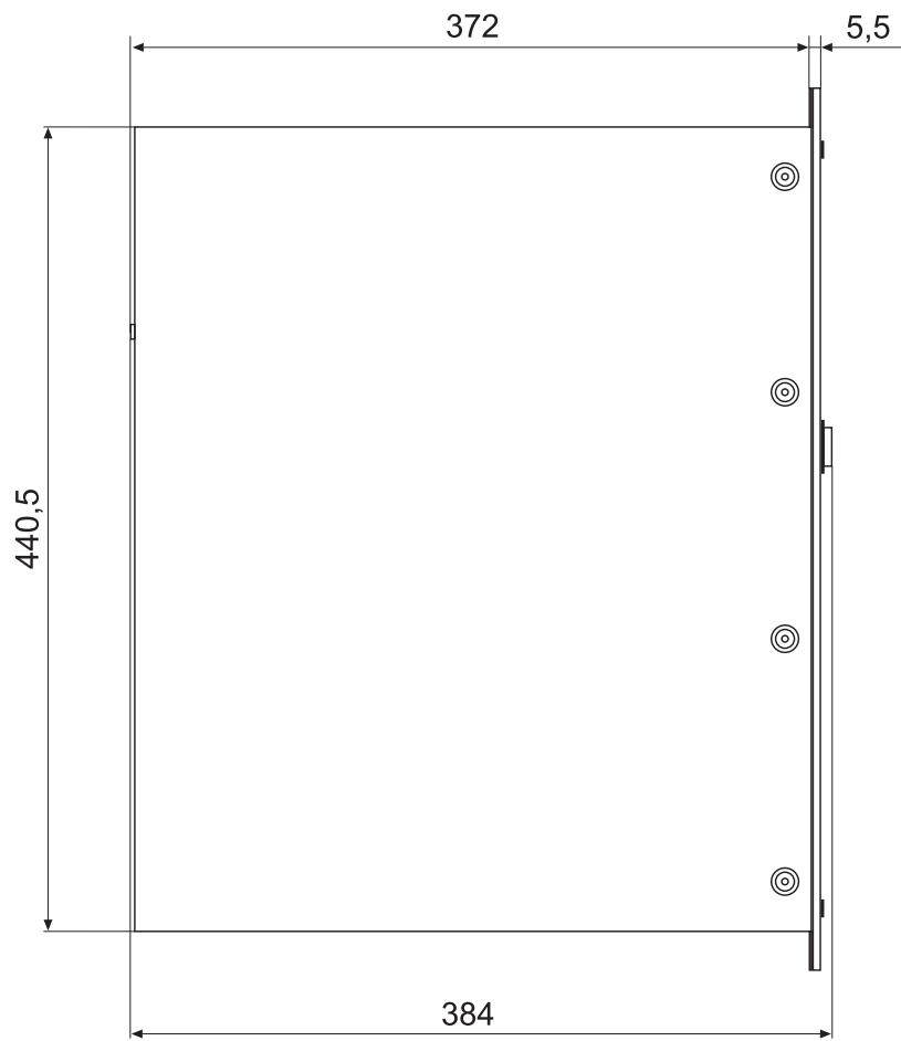
DIMENSIONS/ABMESSAGENGEN 44
INHALT
IMPORTANT SAFETY INSTRUCTIONS

CAUTION
RISK OF ELECTRIC SHOCK DO NOT OPEN

WARNING: TO REDUCE THE RISK OF FIRE OR ELECTRIC SHOCK, DO NOT EXPOSE THIS APPLIANCE TO RAIN OR MOISTURE.
AVIS: RISQUÉ DE CHOC ELECTRIQUE. NE PAS OUVRIR.
WARNING: CONNECT ONLY TO MAINS SOCKET WITH PROTECTIVE EARTHING CONNECTION.
The lightning flash with arrowhead symbol, within an equilateral triangle is intended to alert the user to the presence of uninsulated "dangerous voltage" within the product's enclosure that may be of sufficient magnitude to constitute a risk of electric shock to persons.

The exclamation point within an equilateral triangle is intended to alert the user to the presence of important operating and maintenance (servicing) instructions in the literature accompanying the appliance.
- Read these instructions.
- Keep these instructions.
- Heed all warnings.
- Follow all instructions.
- Do not use this apparatus near water.
- Clean only with a dry cloth.
- Do not block any ventilation openings. Install in accordance with the manufactures instructions.
- Do not install near any heat sources such as radiators, heat registers, stoves, or other apparatus (including amplifiers) that produce heat.
- Do not defeat the safety purpose of the polarized or grounding-type plug. A polarized plug has two blades with one wider than the other. A grounding type plug has two blades and a third grounding prong. The wide blade or the third prong are provided for your safety. If the provided plug does not fit into your outlet, consult an electrician for replacement of the obsolete outlet.
- Protect the power cord from being walked on or pinched particularly at plugs, convenience receptacles, and the point where they exit from the apparatus.
- Only use attachments/accessories specified by the manufacturer.
- Unplug this apparatus during lightning storms or when unused for long periods of time.
Refer all servicing to qualified service personnel. Servicing is required when the apparatus has been damaged in any way, such as power-supply cord or plug is damaged, liquid has been spilled or objects have fallen into the apparatus, the apparatus has been exposed to rain or moisture, does not operate normally, or has been dropped. - Do not expose this equipment to dripping or splashing and ensure that no objects filled with liquids, such as vases, are placed on the equipment.
- To completely disconnect this equipment from the AC Mains, disconnect the power supply cord plug from the AC receptacle.
- The mains plug of the power supply cord shall remain readily operable.

Management of WEEE (waste electrical and electronic equipment) (applicable in Member States of the European Union and other European countries with individual national policies on the management of WEEE) The symbol on the product or on its packaging indicates that this product may not be treated as regular household waste, but has to be disposed through returning it at a Telex dealer.
IMPORTANT SERVICE INSTRUCTIONS
CAUTION:
These servicing instructions are for use by qualified personnel only. To reduce the risk of electric shock, do not perform any servicing other than that obtained in the Operating Instructions unless you are qualified to do so. Refer all servicing to qualified service personnel.
- Security regulations as stated in the EN 60065 (VDE 0860 / IEC 65) and the CSA E65 - 94 have to be obeyed when servicing the appliance.
- Use of a mains separator transformer is mandatory during maintenance while the appliance is opened, needs to be operated and is connected to the mains.
- Switch off the power before retrofitting any extensions, changing the mains voltage or the output voltage.
- The minimum distance between parts carrying mains voltage and any accessible metal piece (metal enclosure), respectively between the mains poles has to be 3mm and needs to be minded at all times. The minimum distance between parts carrying mains voltage and any switches or breakers that are not connected to the mains (secondary parts) has to be 6mm and needs to be minded at all times.
- Replacing special components that are marked in the circuit diagram using the security symbol (Note) is only permissible when using original parts.
- Altering the circuitry without prior consent or advice is not legitimate.
- Any work security regulations that are applicable at the location where the appliance is being serviced have to be strictly obeyed. This applies also to any regulations about the work place itself.
- All instructions concerning the handling of MOS - circuits have to be observed.
NOTE:

SAFETY COMPONENT ( MUST BE REPLACED BY ORIGINAL PART )
Use the POWER switch located on the front panel to power-on the appliance. The soft-start function protects against current inrush peaks on the mains, which in addition prevents the mains line protection switch from activating during power-on. The loudspeaker outputs are activated via relay switching with a delay of approximately 3 seconds to efficiently attenuate eventual power-on noise. The PROTECT LED lights during the delay time and the fans run at maximum speed. This is normal, confirming the protection circuitry's immaculate operation.

POWER
This indicator lights when the power amplifier has been switched on. Causes for the POWER-indicator not lighting are: the appliance is not connected to the mains network or a defective primary fuse

PROTECT
The PROTECT LED lights indicating that one of the internal protection circuits against thermal overload, short-circuit, Back-EMF, HF-occurrence at the output, etc., has been activated. The output relays interrupt the connected load from the power amps while input signals are interrupted as well, preventing the connected loudspeaker systems and the power amplifier itself from being damaged. Whatever caused the fault – e.g. a short-circuited speaker cable – needs to be remedied. In case of thermal overload you have to wait until the power amplifier automatically regains normal operation.

SIGNAL
The SIGNAL LED lights as soon as an audio signal of approximately 30dB below full modulation is present at the output. The LED is dimmed when speaker cables are short-circuited or a protection circuit has been activated

0 dB

The 0dB LED lights whenever the power amplifier is driven at its limits. Higher input voltage does not result in higher peak output voltage. In addition, the 0dB indicator comes in handy when adjusting external limiters.

LIMIT

This indicator lights as soon as one of the integrated dynamic audio signal limiters is being activated and the power amplifier is driven at the clipping limit or generally at its maximum capacity. Short-term blinking is not a problem, because the internal limiter trims input levels of up to +21dBu down to a S/N-ratio of approximately 1% . If, on the other hand, this LED lights constantly, reducing the volume is recommended to prevent the loudspeaker systems connected from being damaged by probable overload.
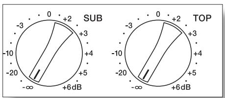
Detent potentiometers scaled in dB for adjusting amplification levels of SUB and TOP channels. To prevent distortion in mixing consoles connected to the amp, setting these controls to a value between 0dB and +6dB is generally recommended. The dB-scale provides direct indication of the control attenuation applied to the fixed internal amplification.
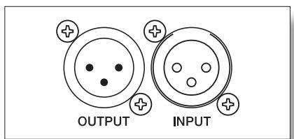
INPUT
The electronically balanced INPUT offers an input sensitivity of 0dBu (775mV) for direct connection of mixing consoles, equalizers, etc.
The XLR-type connector OUTPUT is prepared for "through-connecting" input signals to additional external power amps. The input signal is directly routed to the output connector. There are no repeaters or other electronic components within that signal path. Accordingly, input and output connectors are directly interconnected in parallel, offering permanent electrical connection, without regard to the setting of the Power-ON switch.
NF-CONNECTION CORDS
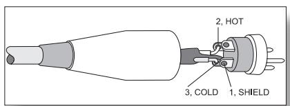
Choosing high-quality balanced cables (two conductors for the audio signal plus separate shielding mesh) with XLR-type connectors is recommended for LF-signal connection. Although connecting unbalanced cables to the power amplifier inputs is possible as well, using balanced cables is always preferable. A great number of today's audio appliances employ balanced outputs. With balanced cabling, the shield connects all metal enclosure parts and therefore efficiently eliminates the introduction of external interference – mostly noise and hum.
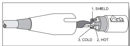
XLR-type connector pin-assignment
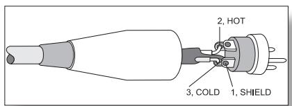
XLR (male)
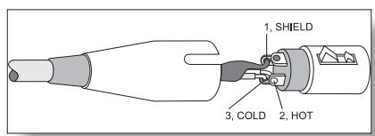
XLR (female)
POWER AMPLIFIER OUTPUT CONNECTORS
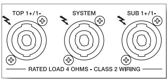
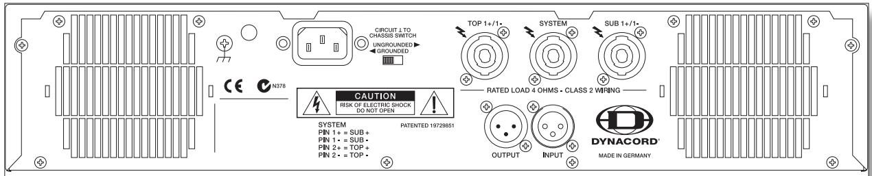
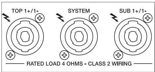
Power amp output connection for SYSTEM, SUB and TOP channels is provided via professional SPEAKON-type output connectors. This mechanically and electrically safe connection method complies with any safety standard allowing the use of high-performance loudspeaker cables with diameters of up to 4 × 2.5mm^2 . The DYNACORD accessory program offers single connectors and couplings as well as high-performance loudspeaker cables.
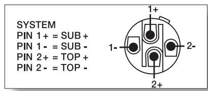
The four poles of the system connector are assigned as follows: the low-frequency signal is present via pins 1+ and 1- while pins 2+ and 2- carry the Mid/ Hi-range audio signal. Using four-pole SPEAKON speaker cables allows quick, trouble-free and correct connection of loudspeaker cabinets that provide system connectors - like FX 12 and FX 20.
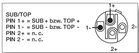
A plastic lid covers SUB and TOP connectors to prevent inadvertent erroneous connection. Remove these covers only in the event that you are going to connect speaker systems that do not provide system connectors. Keep in mind that the bass and mid/hi audio signals are present on the SUB and TOP connectors' pins 1+ and 1-.
Caution:
The FLASH symbol “ ” at the loudspeaker connectors indicates that high voltages are present at these connectors which, when getting in contact, can cause harm to someone's health.
GROUND-LIFT SWITCH
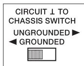
The ground-lift switch allows eliminating noise loops. When operating the power amplifier in a 19" rack-shelf system or cabinet together with other equipment, setting the switch to its GROUNDED position is recommended. When operating the power amplifier together with appliances with differing ground potentials, set the switch to its UNGROUNDED position.
MAINS INPUT
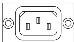
Under normal circumstances, the mains fuse only blows in case of fault. Replacing the fuse is only permissible for authorized service personnel using a new fuse of the same type with identical amperage, voltage and blow characteristics. The high-performance mains cord supplied with your power amplifier complies with applicable safety regulations, plus that its diameter corresponds to the power amp's power output capacity. Whenever possible make sure to use the supplied mains cord for connecting the power amp to the mains network. Using a different mains cord with a smaller diameter results in higher leakage, consequently reducing the amplifier's maximum power output capacity.
The following tables are useful in determining power supply and cabling requirements.
The power drawn from the mains network is converted into acoustic output to feed the connected loudspeaker systems plus heat. The difference between drawn power and dispensed power is referred to as leakage power or dissipation (P_d) . The amount of heat resulting from power dissipation might remain inside of a rack-shelf and needs to be diverted using appropriate measures. The following table is meant as auxiliary means for calculating temperatures inside of rack-shelf systems/cabinets and the ventilation efforts necessary.
The column "Pd" lists the leakage power in relation to different operational states. The column "BTU/hr" shows the dispensed heat amount per hour.
| Xa 4000 | Umains [V] | Imains [A] | Pmains [W] | Pout SUB+TOP [W] | Pd (5) [W] | BTU/hr(1) |
| idle | 230V | 1 | 80 | - | 80 | 273 |
| Max. Output Power @ 8Ω (1) | 230V | 10,6 | 1640 | 600+500 | 540 | 1840 |
| Max. Output Power @ 4Ω (1) | 230V | 18,2 | 3000 | 1100+900 | 1000 | 3410 |
| 1/3 Max. Output Power @ 4Ω (1) | 230V | 10,3 | 1580 | 366+300 | 914 | 3120 |
| 1/8 Max. Output Power @ 4Ω (1) | 230V | 4,5 | 610 | 137+113 | 360 | 1230 |
| 1/8 Max. Output Power @ 4Ω (2) | 230V | 5,5 | 790 | 137+113 | 540 | 1840 |
| 1/8 Max. Output Power @ 4Ω (2), (4) | 254V | 5,5 | 840 | 166+137 | 537 | 1830 |
| Normal Mode (-10dB) @ 4Ω (1) | 230V | 4,1 | 550 | 110+90 | 350 | 1190 |
| Rated Output Power (0dB) @ 4Ω (1) | 230V | 17,2 | 2800 | 1000+800 | 1000 | 3410 |
| Alert (Alarm) Mode (-3dB) @ 4Ω (1) | 230V | 12,3 | 1920 | 500+400 | 1020 | 3480 |
| 1/3 Max. Output Power @ 2Ω (2) | 230V | 16,7 | 2720 | 600+533 | 1587 | 5420 |
| 1/8 Max. Output Power @ 2Ω (1) | 230V | 7,2 | 1050 | 225+200 | 625 | 2130 |
| 1/8 Max. Output Power @ 2Ω (2) | 230V | 8,8 | 1260 | 225+200 | 835 | 2850 |
(1) Sine Signal Modulation (80Hz/1kHz)
(2) Band-limited Pink Noise
(3) 1 BTU = 1055.06 ~J = 1055.06 ~Ws
(4) 10% Mains Over Voltage
(5) Pd = Leakage Power
The following factors allow direct proportional calculation of the power consumption for different mains supply voltages:
$$ 1 0 0 \mathrm {V} = 2. 3; 1 2 0 \mathrm {V} = 1. 9; 2 2 0 \mathrm {V} = 1. 0 5; 2 4 0 \mathrm {V} = 0. 9 6 $$
NOTES ON ADJUSTMENTS
- Turn the EQ controls on the mixing desk to a central position (linear setting).
- Switch any third-octave or octave equalisers to "Bypass" or set the equaliser controls to a central position.
- Connect a microphone and use the SUB and TOP control of the power amplifier to set the signal in such a way that the human voice sounds "natural".
- This concludes the basic system setup.
- Using the EQ controls, a wide variety of microphone and instrument inputs can now be adjusted on the mixing desk to match personal preference.
EQUALISER
Third-octave or octave equalisers should be set very carefully, if at all. With many third-octave or octave equalisers, even slight alterations in Lo or Mid range lead to unacceptable sound falsifications which cannot be eliminated via other EQ controls.
ADJUSTMENTS WITH REAL TIME ANALYSER AND EQUALIZER
"Fine tuning" of amplifier and loudspeaker systems with real time analysers and third-octave or octave equalisers is not normally advisable. Depending on the setting in question, third-octave equalisers in particular cause phase and group time distortions which falsify the sound considerably. The measuring microphone evaluates both the cabinet direct sound field and the reflections simultaneously, thus preventing any proper interpretation of the readings from a sound point of view.
If particularly unfavourable acoustic conditions make fine tuning seem necessary, the following principles should be adhered to when tuning amplifier and speaker systems:
- Only measure in the direct speaker sound field, normally at a distance of 3 - 5 metres maximum. If the measuring microphone is set up further away, (e.g. in the middle of the hall), both direct and room sound is measured. Any attempt to linearize this "blend" with EQ normally produces an extremely mid-, tinny- sounding, obtrusive sound image.
- When measuring in the "critical" range between ca. 250Hz - 5kHz , only cut with the EQ - do not boost on any account! A "gap" in the spectrum is not considered so obtrusive as a "hump". It is essential to avoid substantial increases in the bass range as this would drastically impair the transient response of the entire system.
- When measuring, only work with 5 W maximum capacity (pink noise). This prevents amplifier clipping and related distortions. With conventional noise generators the peak value of the noise voltage is approximately 10 dB higher than the RMS value, meaning that even 5 W amplified power can lead to short-term peaks of up to 50 W.
- Dominant acoustic feedback can sometimes be suppressed somewhat by third-octave equalisers or parametric EQ's. In applications of this nature, great care should be taken to ensure that the gain in volume does not mean reduced clarity and naturalness.
GENERAL INSTALLATION NOTES
- When installing a sound reinforcement system for halls or festival tents over their entire length, the loudspeaker systems have to be set up on the left and right sides of the stage, slightly pointing to the center, resulting in a beam-shape coverage pattern over the length of the hall or festival tent. Placing Mid/Hi cabinets on both sides on top of each other ("STACKING") provides improved long-throw coverage. Stacking the loudspeaker systems in this way almost doubles coverage while at the same time near field reproduction is not too loud.
- When installing a sound reinforcement system for halls or festival tents on the wider wall side, the loudspeaker systems have to be set up on the left and right sides of the stage, aimed towards the audience. Because of the wider horizontal dispersion angle needed ("covering the front and the sides"), this kind of sound reinforcement application can only be satisfactory realized when employing two Mid/Hi cabinets per side. Exceptionally preferable for these applications is the "stack and splay" technique - turning the two MID-HI cabinets, which are placed on top of each other - which results in smoother sound reproduction over the entire audience area.
- In many halls and festival tents low-frequency response can be dramatically improved by placing the woofer systems directly on the floor instead of on the stage. In return this requires installing the Mid/Hi cabinets on loudspeaker pole-stands.
- Arraying woofer systems in a center "cluster" results in extreme low-frequency SPL in the proximity of the "woofer cluster" with SPL dropping rapidly over distance.
- Compared to woofer-cluster-configuration, de-centralized placing the woofer systems on the floor along the edge of the stage results in reduced low-frequency SPL in the audience area next to the stage. De-centralized placing on the floor along the edge of the stage on the other hand provides considerably improved low-frequency response over wider distances.
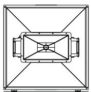
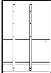
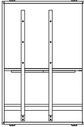
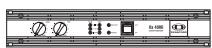
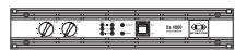
Fig. 1
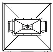
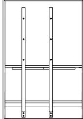
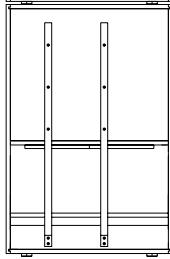
Fig. 1 shows a standard setup consisting of 2x Xa 4000, 2x FX12 used as Mid/Hi cabinets and 4x FX 20 used as woofer cabinets. This all-purpose setup fulfills the requirements of most applications. The use of four FX 20 bass cabinets produces solid low-frequency sound reproduction, which is most favorable for revival and jazz-rock bands as well as for other bass drum-oriented musical styles when performed in medium size clubs or festival tents.
Sound reinforcement of side areas can be realized through employing additional „sidefill" speaker systems, like for example compact 2- or 3-way fullrange cabinets, which are simply connected via the TOP-Speakon socket of the Xa 4000. This connector carries the Mid/Hi audio signal via pins 1+/1- .
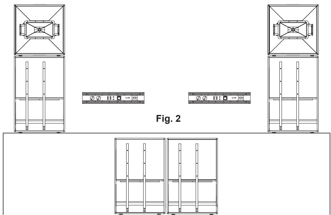
Fig. 2 shows a variation of the standard setup that is advantageous for wider stages. Whenever placing the loudspeaker cabinets on stage is possible, in most cases the use of a single FX 20 woofer to elevate the FX 12 Mid/Hi cabinet in the correct height on top of the woofer is sufficient. The remaining two woofer cabinets are configured as center cluster in the middle and in front of or under the stage providing homogeneous coverage of the audience area. In addition to that extra degree of homogeneous coverage this left-center-right setup allows achieving higher SPL in the low-frequency range.
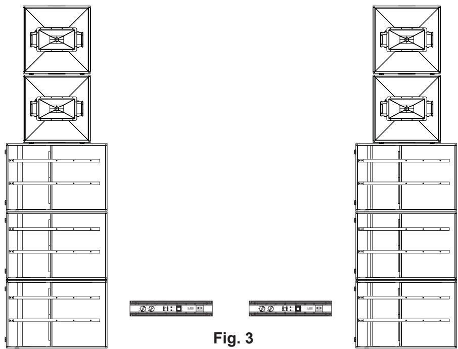
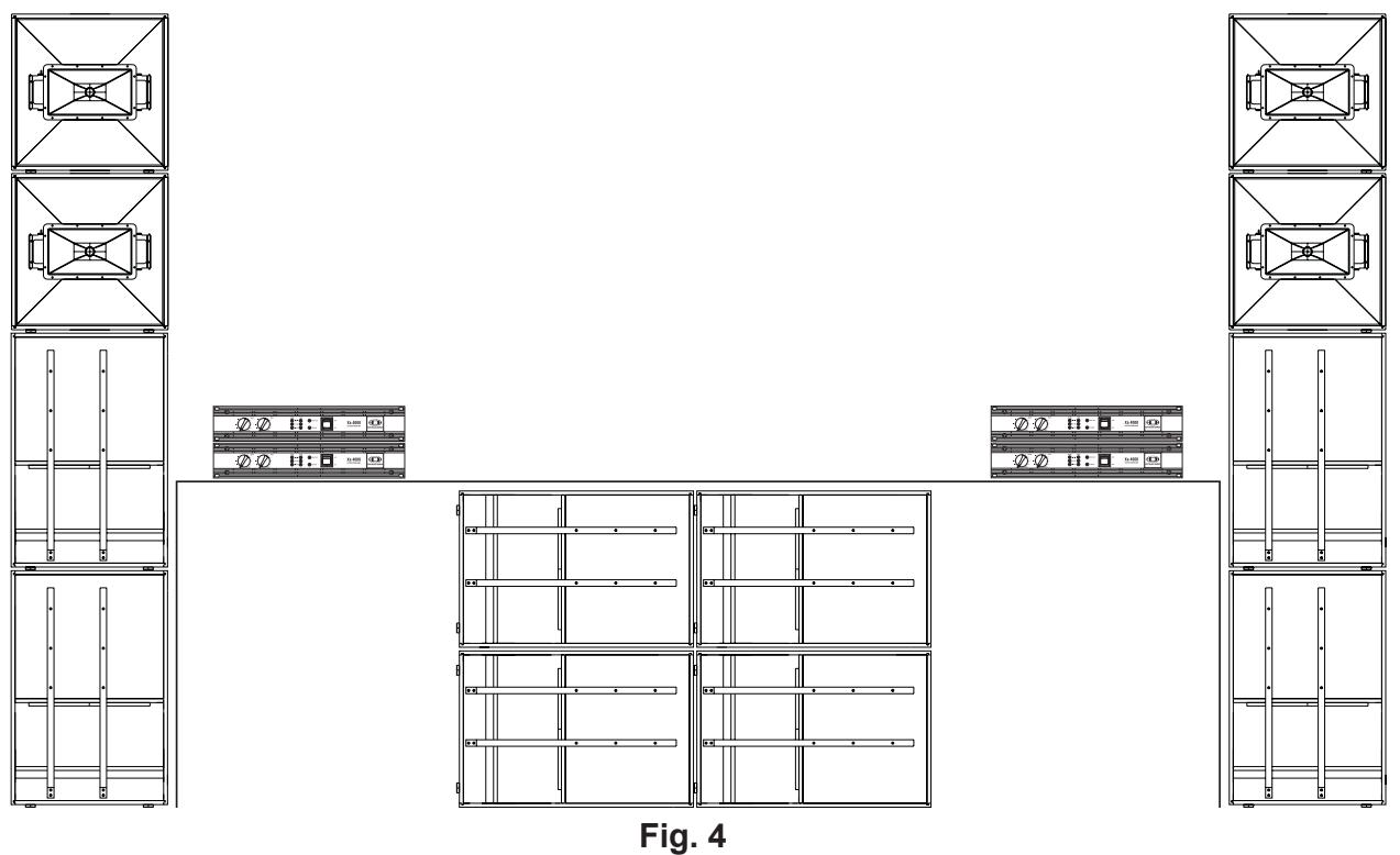
Fig. 3 shows the possibility of how to achieve even higher SPL through employing an additional FX 20 woofer and Mid/Hi cabinets on each side of the stage. Additional cabinets are simply connected in parallel to the existing speaker systems. Of course, configuring woofers in a left-center-right setup – as outlines in Fig. 2 – is possible without problem. Stacking the Mid/Hi cabinets on top of each other almost doubles coverage, without the drawback of too high acoustic output in the proximity of the stage. Using the “stack & splay” technique – turning the stacked Mid/Hi cabinets so that they aim at slightly different angles – even improves coverage of the audience area.
Fig. 4 shows a setup consisting of a complete Xa standard installation per side, which is especially suitable for major clubs and large festival tents up to a size of approximately 3000 sqm. If needed, this configuration allows expanding each Xa system through adding additional loudspeaker cabinets (please refer to Fig. 3). The left-center-right setup delivers noticeably more SPL in the low-frequency range and most of all provides truly homogeneous dispersion and coverage in the audience area, without the annoyance of interference. This configuration is particularly recommendable for wide stages.
WARNING: TO REDUCE THE RISK OF FIRE OR ELECTRIC SHOCK, DO NOT EXPOSE THIS APPLIANCE TO RAIN OR MOISTURE. AVIS: RISQUÉ DE CHOC ELECTRIQUE, NE PAS OUVRIR.
WARNING: CONNECT ONLY TO MAINS SOCKET WITH PROTECTIVE EARTHING CONNECTION.
XLR-type connector pin-assignment
XLR (male)
XLR (female)
ENDSTUFENAUSGANGSBUCHSEN
WARNING: TO REDUCE THE RISK OF FIRE OR ELECTRIC SHOCK, DO NOT EXPOSE THIS APPLIANCE TO RAIN OR MOISTURE.
AVIS: RISQUÉ DE CHOC ELECTRIQUE. NE PAS OUVRIR.
WARNING: CONNECT ONLY TO MAINS SOCKET WITH PROTECTIVE EARTHING CONNECTION.

Amplifier at rated conditions, both channels driven, 8 loads, unless otherwise specified.
| Xa 4000 | SUB | TOP | ||||
| Load Impedance | 2Ω | 4Ω | 8Ω | 2Ω | 4Ω | 8Ω |
| Maximum Midband Output PowerTHD = 1%, 80Hz SUB, 1kHz TOP, Single Channel | 1800W | 1100W | 600W | 1600W | 900W | 500W |
| Rated Output PowerTHD < 0.1%, 20Hz-140Hz SUB, 140Hz-20kHz TOPSingle Channel | ---- | 1000W | 500W | --- | 800W | 400W |
| Maximum RMS Voltage SwingTHD = 1%, 80Hz SUB, 1kHz TOP | 78V | |||||
| Power BandwithTHD = 1%, ref. 1kHz, half power @ 4Ω | 10Hz ... 50kHz | |||||
| Voltage Gainref.1kHz | 37.3dB | |||||
| Input Sensitivityat rated output power, 1kHz | 0dBu (0.775V rms) | |||||
| THD at rated output power,MBW = 80kHz, 1kHz | < 0.05% | |||||
| Maximum Input Level | +22dBu (9.76V rms) | |||||
| Input Impedanceactive balanced | 20kΩ | |||||
| Damping Factor1kHz | > 300 | |||||
| Slew Rate | 30V/μs | |||||
| Signal to Noise Ratio AmplifierA-weighted | 102dB | |||||
| Output Stage Topology | Class H | |||||
| Power Requirements | 240, 230, 220, 120V or 100V; 50Hz ... 60Hz ( factory configured ) | |||||
| Power Consumptionat 1/8 maximum output power @ 4Ω | 850W | |||||
| Protection | Audio limiters, High temperature, DC, HF, Back-EMF,Peak current limiters, Inrush current limiters, Turn-on delay | |||||
| Cooling | Front-to-rear, 3-stage-fans | |||||
| Ambient Temperature Limits | +5°C ... +40°C ( 40°F ... 105°F) | |||||
| Safety Class | I | |||||
| Dimensions(W x H x D), mm | 483 x 88.1 x 384 | |||||
| Weight | 8.25kg(18.2lbs) | |||||
| Optional:Rear-rackmount 15,5"Rear-rackmount 18" | 112930 (RMS15-CL)112933 (RMS18-CL) | |||||
Notes:
- Depending on the ambient temperature, the unit might not operate continuously at 2 load.
- Due to mains voltage in Japan (100V/50Hz) the values for the maximum output power can be decreased up to 15% (only 100V version)!