
POWERMAX 230 - Power amplifier DYNACORD - Free user manual and instructions
Find the device manual for free POWERMAX 230 DYNACORD in PDF.
| Product type | 2-way active crossover controller + mono sub output |
| Brand | DYNACORD |
| Model | POWERMAX 230 |
| Dimensions (W x H x D) | 483 x 43.6 x 226.5 mm |
| Net weight | 3.2 kg |
| Mains power supply | 100-120 V / 220-240 V, 50-60 Hz (selector) |
| Power consumption | 17 W |
| Filter type | PowerMax12 (patent pending) |
| Crossover frequency | 45 Hz - 160 Hz, adjustable |
| Lo-Cut filter | 20 Hz - 100 Hz, 12 dB/octave |
| Bass equalization (LO-EQ) | 50 Hz, Shelving, 0 dB to +12 dB |
| Midrange equalization (MID-EQ) | 4 kHz, Dip, -8 dB to 0 dB |
| Treble equalization (HI-EQ) | 15 kHz, Lift, 0 dB to +8 dB |
| Inputs (CH A and B) | Active balanced, female XLR, 20 kOhm, max +20 dBu |
| Outputs (HI, LO, SUB) | Active balanced, male XLR, 75 Ohm, max +20 dBu |
| Gain | -6 dB to +6 dB (level controls) |
| Dynamic range (A-weighted) | 117 dB |
| Distortion (THD+N, 20 Hz-20 kHz, +6 dBu) | Typical 0.003%, max <0.02% |
| Frequency response (-3 dB, ref 1 kHz) | 16 Hz - 150 kHz |
| Level control attenuation | > 80 dB |
| Safety | Output audio relays, Mute switches, protection against inadvertent switching |
| Cleaning and maintenance | Damp cloth; do not obstruct ventilation openings |
| Manufacturer warranty | 36 months (except misuse or unqualified intervention) |
| Transformer option | NRS 90208 |
Frequently Asked Questions - POWERMAX 230 DYNACORD
User questions about POWERMAX 230 DYNACORD
0 question about this device. Answer the ones you know or ask your own.
Ask a new question about this device
Download the instructions for your Power amplifier in PDF format for free! Find your manual POWERMAX 230 - DYNACORD and take your electronic device back in hand. On this page are published all the documents necessary for the use of your device. POWERMAX 230 by DYNACORD.
USER MANUAL POWERMAX 230 DYNACORD
Frequenzgang, -3dB ref. 1kHz, Lo-Cut 20Hz
50Hz, shelving, 0dB ... +12dB
4kHz, Absenkung, -8dB ... 0dB
15kHz, Anhebung, 0dB ... +8dB
aktiv symmetrisch, XLR-F Buchse
20kOhm
+20dBu
+6dBu
- + 6 ~dB
XLR-M Stecker
aktiv symmetrisch, XLR-M Stecker
75 Ohm
+20dBu
+6dBu
- ... +6dBu
16Hz ... 150kHz
0dB
+12dB
117dB
< 0.02%
0.003%
-80dB
90dB
80dB
100V ... 120V, 220V ... 240V
17W
483× 43,6× 226,5
3,2 kg
NRS 90208
*Patent angemeldet
IMPORTANT SAFETY INSTRUCTIONS

CAUTION
RSK OF ELECTRIC SHOCK DO NOT OPEN
WARNING: TO REDUCE THE RISK OF FIRE OR ELECTRIC SHOCK, DO NOT EXPOSE THIS APPLIANCE TO RAIN OR MOISTURE.
AVIS: RISOUE DE CHOC ELECTRIQUE. NE PAS OUVRIR.

The lightning flash with arrowhead symbol, within an equilateral triangle is intended to alert the user to the presence of uninsulated "dangerous voltage" within the product's enclosure that may be of sufficient magnitude to constitute a risk of electric shock to persons.

The exclamation point within an equilateral triangle is intended to alert the user to the presence of important operating and maintenance (servicing) instructions in the literature accompanying the appliance.
- Read these instructions.
- Keep these instructions.
- Heed all warnings.
- Follow all instructions.
- Do not use this apparatus near water.
- Clean only with a damp cloth.
- Do not block any of the ventilation openings. Install in accordance with the manufactures instructions.
- Do not install near any heat sources such as radiators, heat registers, stoves, or other apparatus that produce heat.
- Only use attachments/accessories specified by the manufacturer.
- Refer all servicing to qualified service personnel. Servicing is required when the apparatus has been damaged in any way, such as power-supply cord or plug is damaged, liquid has been spilled or objects have fallen into the apparatus, the apparatus has been exposed to rain or moisture, does not operate normally, or has been dropped.
For US and CANADA only:
Do not defeat the safety purpose of the grounding-type plug. A grounding type plug has two blades and a third grounding prong.
The wide blade or the third prong are provided for your safety. When the provided plug does not fit into your outlet, consult an electrician for replacement of the obsolete outlet.
IMPORTANT SERVICE INSTRUCTIONS
CAUTION: These servicing instructions are for use by qualified personnel only. To reduce the risk of electric shock, do not perform any servicing other than that contained in the Operating Instructions unless you are qualified to do so. Refer all servicing to qualified service personnel.
- Security regulations as stated in the EN 60065 (VDE 0860 / IEC 65) and the CSA E65 - 94 have to be obeyed when servicing the appliance.
- Use of a mains separator transformer is mandatory during maintenance while the appliance is opened, needs to be operated and is connected to the mains
- Switch off the power before retrofitting any extensions, changing the mains voltage or the output voltage.
- The minimum distance between parts carrying mains voltage and any accessible metal piece (metal enclosure), respectively between the mains poles has to be 3mm and needs to be minded at all times. The minimum distance between parts carrying mains voltage and any switches or breakers that are not connected to the mains (secondary parts) has to be 6mm and needs to be minded at all times.
- Replacing special components that are marked in the circuit diagram using the security symbol (Note) is only permissible when using original parts.
- Altering the circuitry without prior consent or advice is not legitimate.
- Any work security regulations that are applicable at the location where the appliance is being serviced have to be strictly obeyed. This applies also to any regulations about the work place itself.
- All instructions concerning the handling of MOS - circuits have to be observed.

SAFETY COMPONENT (HAS TO BE REPLACED WITH ORIGINAL PART ONLY)
CONTENTS
Introduction. 9
Front Panel 10
Rear Panel 11
Specifications 13
Block diagram. 20
Dimensions 21
Warranty 24
PowerMax230
Meeting the highest requirements of modern audio applications - especially, when it comes to sound pressure level, coverage and sound quality - is only possible when using active multi-component loudspeaker systems which provide the possibility to separately amplify and reproduce the audio signal's individual frequency ranges. Active 2-way installations with additional subwoofer systems probably offer the best price-performance ratio. The low frequency range of the audio signal is reproduced by the sub woofer while high-quality full-range cabinets take care of the Mid/Hi frequencies and vocals.
One of the essential advantages when using active 2-way systems with additional sub woofers is the fact that the vocals are not divided between several speaker systems. This, in return, offers more convenience when adjusting the sound system. Unlike than with active 3- or 4-way configurations – difficult analyzing and measuring of sound fields is unnecessary.
Since locating low-frequency sound is merely impossible, simply using monaural sub woofers is absolutely sufficient for smaller stages or rooms. On wider stages it is indispensable to use individual sub woofer systems for both sides. Otherwise, the level differences between bass and treble would result in audible degradation of the overall sound. Of course, adding a centrally located sub woofer might additionally improve the sound quality.
The PowerMax230 Controller has been designed to be used in high-performance installations that employ active 2-way systems plus sub woofers. Applications like these also mostly incorporate professional linear power amplifiers like the DYNACORD L1000, L1600, L2400 or S900, S1200. When using processor controlled power amplifiers like the DYNACORD P1050, the processor section is simply switched off.
Installing and operating the PowerMax230 Controllers is easy as can be since the user does not need to know any complex detail about crossover functions and equalization. All controls for matching the sound to different acoustic conditions and loudspeaker systems are located on the front panel. Difficult tasks - like electronic signal routing and settings for instance - are automatically carried out inside the appliance. The newly designed PowerMax12 crossover function (patents pending) optimally utilizes amplifier output power and loudspeaker transmission capacities. Compared to conventional crossovers or controllers, this results in an improved overall sound quality which is achieved with less effort.
The PowerMax230 Controller is also most suitable for integration in active 2-way instrument reinforcement applications for keyboards, E-bass and drums. The PowerMax12 crossover function eliminates the often complained about "lack-of-punch-and-definition", like it is common for conventional active musical instrument reinforcement systems.
Its excellent dynamic range of more than 116dB, the extremely low noise level and the outstanding price-performance ratio makes the PowerMax230 Controller an advantageous alternative to conventional crossover and controller solutions – even in the critical field of permanent installation.
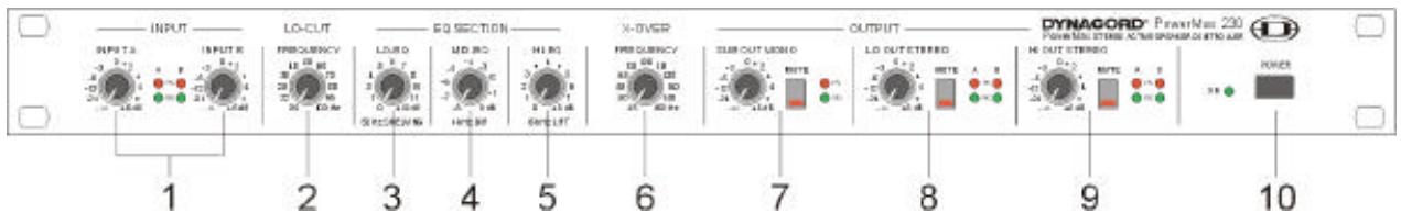
1. Input "A" and "B" level controls
These controls are normally set to their "0"-marked (detent) center position.
If needed or desired, the controls can be used to individually adjust the input levels of the channels "A" and "B". The green "Signal" LEDs indicate that audio signals are present at the inputs. The red "Peak" LEDs light whenever the audio signal is clipped inside the PowerMax230 which might result in distortion. In case the "Peak" LEDs light continuously, lowering of the input levels is recommended to maintain the entire dynamic range.
2. Lo-Cut filter control
This control is normally set to its center (50Hz) position.
The filter is used to eliminate unwanted low-frequency noise.
3. Lo-EQ control
This control is normally set to its center (6dB) position and it is used to correct the frequency response of the subwoofer systems. When the control is set to its clockwise margin, low bass frequencies are amplified by +12dB . The audio signal stays unaltered when the control is positioned at its counter-clockwise margin.
4. Mid-EQ control
This control is normally set to its center (-4dB) position.
It is used to increase the audio level in the 4kHz range. Setting the control to its clockwise margin results in no change in the frequency response but delivers the farthest coverage of the sound reinforcement system. Setting the control to its counter-clockwise margin provides pleasant audio even in the near field of the loudspeaker systems.
5. Hi-EQ control
This control is normally set to its center (4dB) position.
The control is used to increase the audio signal's high frequency range which allows to accomplish improved intelligibility and brilliance even when using loudspeaker systems with diminished treble characteristics. Setting the control to its counter-clockwise margin leaves the high frequency response unaltered.
6. X-over frequency control
The control is normally set to its center (100Hz) position.
This sets the crossover frequency between subwoofer (LO OUT) and full-range cabinets (HI OUT) to 100Hz . Reproduction of the fundamental frequencies of the vocals is mainly taken care of by the full-range cabinets. Best results in coverage and vocal dynamic are achieved when shifting the crossover frequency to approximately 140Hz ; a setting that gets widely used in live music sound reinforcement applications. Setting the crossover point at approximately 70Hz results in optimally locatable vocals and average coverage. This setting is often used when reproducing CDs or other pre-recorded audio programs. With the PowerMax12 x-over function, setting the crossover frequency is extremely uncritical. Often enough, when the system is operated at medium sound pressure levels, changes are not registered. Only when operating the reinforcement system at extremely high levels and depending on the actual setting of the
crossover frequency, minor differences in the subjective peak dynamic of the low frequency range and in the coverage of mid frequency band can be heard.
7. Sub Out Mono control
The control is normally set to its center (0dB) position.
This control is used to adjust the loudness level of the summed low-frequency audio signal of the two channels "A" and "B", which serves to feed a connected monaural sub woofer power amplifier. The "Mute" switch attenuates the Sub Out Mono audio signal, which allows to easily check the entire sound reinforcement system. The green "Signal" LED indicates the presence of an audio signal while the red "Peak" LED lights when the audio signal is clipped inside the PowerMax230 which might result in distortion. In case the "Peak" LED lights continuously, lowering the input "A" and input "B" level controls is recommended to maintain the entire dynamic range.
8. Lo Out Stereo
The control is normally set to its center (0dB) position.
This control is used to adjust the loudness level of the low-frequency audio signals of the two channels "A" and "B", which serves to feed a connected sub woofer stereo power amplifier or two separate power amplifiers, respectively. The "Mute" switch attenuates the Sub Out Stereo audio signal, which allows to easily check the entire sound reinforcement system. The green "Signal" LED indicates the presence of audio signals while the red "Peak" LED lights when the audio signals are clipped inside the PowerMax230 which might result in distortion. In case the "Peak" LED lights continuously, lowering the input "A" and input "B" level controls is recommended to maintain the entire dynamic range.
9. Hi Out Stereo
The control is normally set to its center (0dB) position.
This control is used to adjust the loudness level of the connected full-range or mid-hi cabinet power amplifiers. The "Mute" switch attenuates the Hi Out Stereo audio signal, which allows to easily check the entire sound reinforcement system. The green "Signal" LED indicates the presence of audio signals while the red "Peak" LED lights when the audio signals are clipped inside the PowerMax230 which might result in distortion. In case the "Peak" LED lights continuously, lowering the input "A" and input "B" level controls is recommended to maintain the entire dynamic range.
10. Power-On switch
The PowerMax230's outputs employ high quality audio relays. This ensures that no switching noise or any other noise deriving from erroneously or inadvertently separating the appliance from the mains will cause any harm to the connected loudspeaker systems.
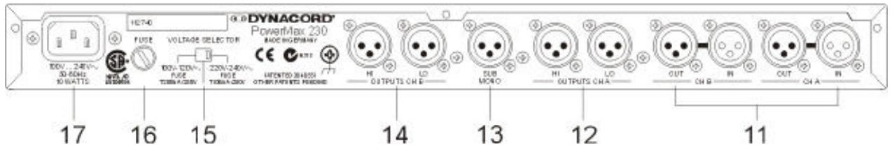
11. Input connectors of channel "A" (CH A IN) and channel "B" (CH B IN)
The PowerMax230 Controller's inputs are electronically balanced (pin2 = +, pin3 = -, pin1 = shield). The OUT- connectors are parallel-wired with their corresponding IN- connectors. This thru-connection allows to easily and conveniently feed additional gear with the original input audio signals.
12. Output connectors of channel "A" (CH A LO, HI)
The PowerMax230 Controller's outputs are electronically balanced (pin2 = +, pin3 = -, pin1 = shield). The low-frequency audio signal feeding channel "A" of the sub woofer power amplifier is present at the LO-output.
The mid-high-frequency audio signal feeding channel "A" of the mid-hi or full-range power amplifier is present at the HI-output.
13. SUB MONO output
The PowerMax230 Controller's outputs are electronically balanced (pin2 = +, pin3 = -, pin1 = shield). This output is meant for the connection of an additional active center sub woofer or sub woofer power amplifier. The output provides the summed monaural audio signal of the two LO-outputs.
14. Output connectors of channel "B" (CH B LO, HI)
The PowerMax230 Controller's outputs are electronically balanced (pin2 = +, pin3 = -, pin1 = shield). The low-frequency audio signal feeding channel "B" of the sub woofer power amplifier is present at the LO-output. The mid-high-frequency audio signal feeding channel "B" of the mid-hi or full-range power amplifier is present at the HI-output.
15. Mains selector switch
Slide switch to select the correct mains voltage 100V/120V or 230V/240V.
When switching the mains voltage always disconnect the appliance from the mains.
When changing the mains voltage range, replacing the mains fuse by the appropriate type is absolutely mandatory. Correct types and values are marked on a label on the rear panel of the appliance.
16. Fuse holder
When switching the mains voltage always disconnect the appliance from the mains.
When changing the mains voltage range, replacing the mains fuse by the appropriate type is absolutely mandatory. Correct types and values are marked on a label on the rear panel of the appliance.
17. Mains connector
Please, make sure to only use the supplied mains cord to connect the appliance to a mains wall outlet.
Technical Specifications PowerMax230
All level and frequency controls in center position, Lo-EQ and Hi-EQ controls at 0dB, MID-EQ control at -4dB, unless otherwise specified. Note: 0dBu = 0.775V
Crossover
Mode
Frequency, sweepable
Filter Type
LO-Cut
Filter Type
Frequency, sweepable
Equalization
LO-EQ
MID-EQ
HI-EQ
Inputs A, B
Type
Input Impedance
Maximum Level
Rated Level
Gain Range
Parallel Outputs A, B
Outputs HI, LO, SUB
Type
Output Impedance
Maximum Level
Rated Level
Gain Range
Frequency Response, -3dB @ 1kHz, Lo-Cut 20Hz
Nominal Gain
Maximum Gain
Dynamic Range, +20dBu, noise A-weighted
THD+N, 20Hz ... 20kHz, +6dBu
THD + N ,typical, +6dBu
Crosstalk Attenuation
Mute Switch Rejection
Level Control Attenuation
Power Requirements, 50Hz....60Hz, voltage selector
Power Consumption
Dimensions, (WxHxD), mm
Weight
Optional, input transformer
2-Way-Stereo + SUB Mono
45Hz ... 160Hz
PowerMax12*
12dB/octave
20Hz ... 100Hz
50Hz, Shelving, 0dB ... +12dB
4kHz, Dip, -8dB ... 0dB
15kHz, Lift, 0dB ... +8dB
Active Balanced, XLR-female
20kohms
+20dBu
+6dBu
- +6dB
XLR-male
Active Balanced, XLR-male
75 ohms
+20dBu
+6dBu
- +6dB
16Hz ... 150kHz
0dB
+12dB
117dB
< 0.02%
0.003%
80dB
90dB
80dB
100V ... 120V, 220V ... 240V
17 W
483× 43.6× 226.5
3.2 kg
NRS 90208
*Patents pending
IMPORTANT INFORMATIONS DE SECURITÉ
16. Compartment fusible
Dimensions, (LxHxP), mm
Poids
The manufacturer's warranty covers all substantial defects in materials and workmanship for a period of 36 months from the date of purchase.
Liability claims are accepted solely, when a valid - correctly and completely filled out - Warranty Registration form is presented by the original owner of the product. The warranty does not cover damage that results from improper or inadequate treatment or maintenance. In case of alteration or unauthorized repairs, the warranty is automatically terminated.