
MP7 - Mixer DYNACORD - Free user manual and instructions
Find the device manual for free MP7 DYNACORD in PDF.
| Product Type | Stereo Powered Mixer |
| Brand | DYNACORD |
| Model | MP7 |
| Built-in Amplifier | 2 x 300 W at 4 ohms |
| Microphone Inputs | 2 balanced XLR channels with +24 V phantom power |
| Line Inputs | 2 balanced TRS jack channels |
| Stereo Inputs | 4 pairs (2 with RIAA equalization for turntables) |
| Speaker Outputs | 2 Speakon connectors (Left/Right) |
| Internal Effects | 2 independent 18-bit multi-effects, 99 presets each (FX1 and FX2) |
| Equalizer | Graphic 7-band stereo with ±10 dB gain |
| Transition Fader | Assignable crossfader on stereo channels |
| Headphone Monitoring | 2 stereo jack sockets (front panel and control surface) |
| Line Outputs | Master A (XLR), Master B (jack), Mono Out, Sub Out, Record Send |
| Lighting | Port for Littlite lamp (12 V / 2.4 W max) |
| Special Functions | Talk-over, PFL/PGM Split, LO CUT filter 80 Hz |
| Dimensions (approx.) | 482 x 133 x 400 mm (19" rack, 3U) |
| Weight | Approximately 12 kg |
| Power Supply | Mains 230 V / 115 V AC, cable supplied |
| Maintenance | Clean with a damp cloth; do not obstruct ventilation grilles |
| Safety | Thermal protection, limiter, SOAR protection, compliant with EN 60065 |
Frequently Asked Questions - MP7 DYNACORD
User questions about MP7 DYNACORD
0 question about this device. Answer the ones you know or ask your own.
Ask a new question about this device
Download the instructions for your Mixer in PDF format for free! Find your manual MP7 - DYNACORD and take your electronic device back in hand. On this page are published all the documents necessary for the use of your device. MP7 by DYNACORD.
USER MANUAL MP7 DYNACORD
WARNING: TO REDUCE THE RISK OF FIRE OR ELECTRIC SHOCK, DO NOT EXPOSE THIS APPLIANCE TO RAIN OR MOISTURE. AVIS: RISOUE DE CHOC ELECTROQUE. NE PAS OUVRIR.


49. PFL/PGM SPLIT LED
IMPORTANT SAFETY INSTRUCTIONS
CAUTION
RISK OF ELECTRIC SHOCK DO NOT OPEN

WARNING: TO REDUCE THE RISK OF FIRE OR ELECTRIC SHOCK. DO NOT EXPOSE THIS APPLIANCE TO RAIN OR MOISTURE.
AVIS: RISOUE DE CHOC ELECTRIQUE. NE PAS OUVRIR.

The lightning flash with arrowhead symbol, within an equilateral triangle is intended to alert the user to the presence of uninsulated "dangerous voltage" within the product's enclosure that may be of sufficient magnitude to constitute a risk of electric shock to persons.

The exclamation point within an equilateral triangle is intended to alert the user to the presence of important operating and maintenance (servicing) instructions in the literature accompanying the appliance.
- Read these instructions.
- Keep these instructions.
- Heed all warnings.
- Follow all instructions.
- Do not use this apparatus near water.
- Clean only with a dry cloth.
- Do not block any of the ventilation openings. Install in accordance with the manufacturer's instructions.
- Install only in rack with back cover.
- Only use attachments/accessories specified by the manufacturer.
- Refer all servicing to qualified service personnel. Servicing is required when the apparatus has been damaged in any way, such as power-supply cord or plug is damaged, liquid has been spilled or objects have fallen into the apparatus, the apparatus has been exposed to rain or moisture, does not operate normally, or has been dropped.
- To completely disconnect mains power from this apparatus, the power supply cord must be unplugged
For US, CANADA and Japan only:
Do not defeat the safety purpose of the grounding-type plug. A grounding type plug has two blades and a third grounding prong. The wide blade or the third prong are provided for your safety. When the provided plug does not fit into your outlet, consult an electrician for replacement of the obsolete outlet.
IMPORTANT SERVICE INSTRUCTIONS
CAUTION: These servicing instructions are for use by qualified personnel only. To reduce the risk of electric shock, do not perform any servicing other than that contained in the Operating Instructions unless you are qualified to do so. Refer all servicing to qualified service personnel.
- Security regulations as stated in the EN 60065 (VDE 0860) and the CSA E60065-00 have to be obeyed when servicing the appliance.
- Use of a mains separator transformer is mandatory during maintenance while the appliance is opened, needs to be operated and is connected to the mains
- Switch off the power before retrofitting any extensions, changing the mains voltage or the output voltage.
- The minimum distance between parts carrying mains voltage and any accessible metal piece (metal enclosure), respectively between the mains poles has to be 3mm and needs to be minded at all times. The minimum distance between parts carrying mains voltage and any switches or breakers that are not connected to the mains (secondary parts) has to be 6mm and needs to be minded at all times.
- Replacing special components that are marked in the circuit diagram using the security symbol (Note) is only permissible when using original parts.
- Altering the circuitry without prior consent or advice is not legitimate.
- Any work security regulations that are applicable at the location where the appliance is being serviced have to be strictly obeyed. This applies also to any regulations about the work place itself.
- All instructions concerning the handling of MOS - circuits have to be observed.
Note:

SAFETY COMPONENT (HAS TO BE REPLACED WITH ORIGINAL PART ONLY)
CONTENTS
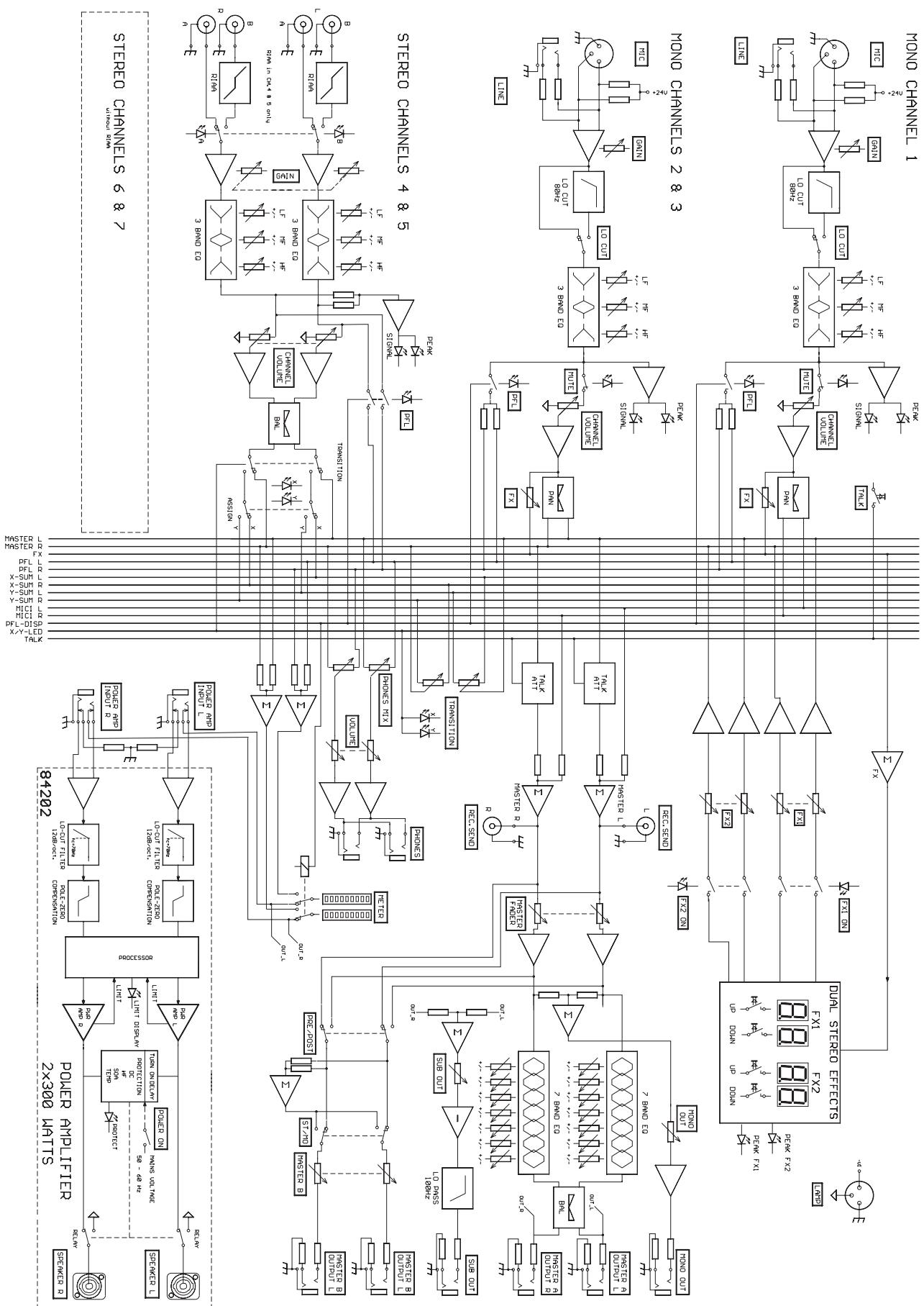
Introduction. 23
Input/Mono 24
Input/Stereo 28
Effect 31
Transition/Phones 33
Master 34
Rear panel 37
Standard installation 38
Specifications 62
Block diagram. 63
Dimensions. 64
Warranty 68
Congratulations!
You will find out that purchasing a MP7 Entertainment System was an excellent decision.
The design of the MP7 is based on decades of experience, research and development as well as a steadfast manufacturer-customer-relationship in the professional audio market. With the MP7 you own a power mixer that offers a wide range of functionality in a truly compact frame. All the troubling experience with cabling and matching mixers, amplifiers, FX-units and equalizers now belongs to history. The mixer's ergonomic layout and clearly structured controls allow instant access at all times. The MP7 additionally provides the possibility for connecting a litlite to compensate for poor lighting in a live mixing environment. Recessed carrying handles in both side panels and an extremely sturdy transport coverlid protecting the controls ensure easy and safe transportation. Besides, if you want to include your MP7 in a 19" rack system, the only thing you have to do is to exchange the side panels for metal rack ears. Its powerful 2x300W/4ohms power amp, a huge amount of functions, high dynamic range, low-noise design and its 18-bit Dual-Stereo FX-section, the MP7 is best equipped for universal use.
The MP7 is going to fulfill all your expectations that you can possibly demand of an Entertainment System.
Use this owner's manual as a guide when exploring the capabilities of your MP7. The vast amount of integrated functions is all explained systematically and point-by-point. Moreover, you will find some useful tips on how to overcome general difficulties during live-performance applications.
Unpacking and Warranty
Open the packaging and carefully take out the MP7. Detach the protective foil covering the FX-unit display. In addition to this owner's manual you will find the mains cord and the warranty card. Please make sure that the warranty registration form is filled out correctly. You will be able to apply for warranty claims only when this form has been completed. We grant 36 months of warranty, starting with the date of the original purchase. Therefore we ask you to also keep the original certificate of purchase, stating the date of purchase. Experience has shown that keeping the original packing as well as carefully storing all documents accompanying the appliance generally increases the price when reselling the device.
Installation and Connections
Always install the MP7 on an even surface to allow for sufficient airflow during operation. The device is equipped with an electronically controlled fan to protect the power amplifier section against thermal overload. The ventilation direction is Front-to-Rear. Fresh, cold air enters the mixer at its front side and warm air leaves the appliance through the ventilation louvers in the rear panel. Do not cover the frontal or the rear ventilation louvers, since otherwise, the MP7 would automatically enter protect mode, preventing damage through thermal overload. When protect mode is engaged, the device is not going to be damaged. Nevertheless, regular operation is not possible during this period of time. In case you have decided to install the MP7 in a 19" rack system, make sure to leave at least 2RU of room above and at least 1RU of empty space below the appliance. Of course, you can cover the resulting gaps in the rack system using optionally available blinds with ventilation louvers. Before establishing the mains connection, please make sure that the appliance matches the voltage and frequency of your local mains supply. Mind the label next to the mains switch stating the operation voltage your MP7 is factory-preset to. When switching the MP7's power on, the internal fan will run for approximately 2 seconds at full speed. This is to provide you with an acoustic signal that the mixer is ready for operation. Additionally, any dust particles that might have gotten into the enclosure are blown out. The SPEAKER OUTPUTS on the rear panel of the MP7 are provided through professional standard SPEAKON high-performance connectors, which offer absolute secure connection. The pin-assignment of these sockets is 1+ (hot) and 1- (cold).

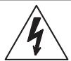
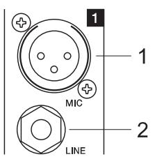
1. MIC
Electronically balanced XLR-type inputs (identical to the ones found on major studio and live sound mixing consoles) for connecting low-impedance microphones. The input stage provides extremely low noise and low hum signal processing at an outstandingly low distortion rate (<0.002% typically) even in the high frequency range. Generally, any type of
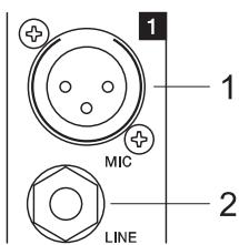
microphone can be connected as long as its pin assignment is in accordance with the diagram shown aside. Connecting condenser-type microphones is no problem. In that case the connected microphone gets its power supply (+24V) directly from the mixer. So, battery replacement belongs to the past.
Using dynamic and condenser microphones together on these
inputs is generally possible. Nevertheless, please make sure to consider the owner's manual of the employed microphones. The MIC-inputs are capable of handling levels in the range between -60dBu ... + 11dBu; depending on the setting of the corresponding gain control. Because of their design, which is especially matched for connecting low-impedance microphones as well as their phantom power capability these XLR-inputs are not suitable for the connection of additional mixing consoles, FX-units, keyboard instruments, or other electronic gear. When connecting this kind of equipment, please utilize the LINE-inputs.
2. LINE
Electronically balanced inputs for the connection of electronic instruments, such as keyboards, drum computers, E-guitars and E-basses with an active output, as well as all other high level signal sources, like additional mixers, FX units, CD player, etc. The LINE-inputs have been designed to handle levels in the range between -40dBu ... + 30dBu. Connecting balanced or unbalanced signal sources is equally possible using monaural or stereo phone plugs, with their pin-assignment matching the diagram. If the device that is going to be connected is furnished with a balanced output stage, using balanced cables with stereo phone plugs is certainly preferable. This type of connection is greatly insensitive to the induction of external noise or HF interference.
Do not connect signal sources to a channel's MIC and the LINE inputs at the same time, since the signals cause mutual interference, which results in level reduction.
When connecting signal sources, please make sure that the corresponding channel faders or at least the master faders are at their minimum settings. This will save yourself, your audience, and the equipment from extensive wear from unpleasant plug-in noise.
3. LO CUT 80Hz
The LOCUT-switch allows muting frequencies below 80Hz by 18dB per octave. Especially for microphone applications using the LO CUT filter is good advice, since it efficiently suppresses popping sounds and rumbling noise as well as low-frequency feedback. Additionally, in most cases activating the LO CUT filter allows boosting the bass, without having the unwanted "booming".
Another welcome side effect is, that the power amplifier and the connected loudspeaker systems are not "polluted" by low-frequency interference "closing off" the sound system, which certainly is not in yours or the audience's interest. Your speaker systems will provide you with a truly clear, natural, and powerful sound performance when using the Lo CUT filter.
4. GAIN
Rotary control for adjusting the MIC or LINE inputs' sensitivity, while optimally matching the incoming signals to the mixer's internal operation level. Cautious adjusting offers the benefits of an improved S/N-ration and provides you with the full bandwidth of the MP7's outstanding sound capabilities. On the XLR-type connectors an amplification of +10dB is achieved when the control is set all the way to the left and +60dB when the control is set to its maximum position to the right. Especially when dealing with very low input levels, like they occur during vocal recordings or when picking up distant sound sources, the high gain is extremely profitable. Using the LINE-input, the signal is generally attenuated by -20 dB, while maintaining the total adjustment range of 50dB. The LINE-input's unity gain - no amplification (0 dB) - is achieved at the 20dB mark. The following is meant as a short note for your assistance on how to determine the correct input level.
Note on how to set the input level:
- Set the gain control and the corresponding channel fader to their minimum setting.
- Connect the desired sound source (microphone, musical instrument, ...) to the corresponding MIC or LINE input.
- Play the sound source at its highest volume setting; respectively, sing or speak as loud as possible directly into the microphone.
- While doing so, adjust the input level using the gain control, so that during the loudest passages the PEAK LED is just not lit, but the SIGNAL-LED lights constantly.
This is the basic channel setting, leaving you with at least 8dB of headroom. Which means, you have at least a range of 8dB before signal clipping. In case you intend to make further adjustments to the channel's EQ setting, you should perform steps 3. and 4. again afterwards, since changes in the sound shaping section also influence the channel's overall level.
5. EQ SECTION
The mixer's EQ section allows very differentiated shaping of the incoming audio signal within different frequency bands. Turning an EQ level control to the right enhances / amplifies the corresponding frequency range while turning it to the left lowers / attenuates the signal of that specific frequency band. Before altering to the sound, all EQ controls should be set to their neutral position; i.e. their markers point straight up (detent position). If possible, do not set the EQ controls to extreme positions. Usually, minor changes are totally sufficient and produce the best results in the overall sound. You should use a natural sounding reproduction as an orientation mark and rely on your musically trained ear, which still is one of the best instruments for judging the sound quality. Try to avoid excessive enhancement of the MID band. The moderate use of the MID control is the best remedy to avoid acoustical
feedback. Lowering the frequency band's level more or less will provide you with high amplification rates without feedback. Set the LO-EQ in accordance to your personal taste, for instance to achieve the desired, voluminous vocal sound. Use the HI-EQ to provide vocals with more crisp.
6. PAN
The setting of the PAN control defines the input signal's position within the stereo image. When set to its center position, the audio signal is fed with equal levels to the left and right master busses. The PAN section's design ensures that the overall relative level of an audio signal is maintained, no matter to what position within the stereo image the PAN control is set.
7. FX1/2
Using the FX1/2 control lets you route the corresponding input signal to the integrated digital effects units FX1 or FX2 at variable levels. In this way assigning special effects to musical instruments or vocals is fairly simple. When establishing an effect-mix, it is good advice to start with all FX-controls set to their center position. From this point you can increase or reduce the effect's intensity, depending on your personal preferences. Please make sure to carefully monitor the PEAK LED's in the FX1/2 channels during a performance. The indicator should only light briefly at the occurrence of peak signals. If the LED lights constantly, it is strongly recommended to lower the affected channels' send levels at their FX1/2 controls. For further information, please refer also to the paragraphs on the FX1/2 units.

8. MUTE
Engaging the MUTE button mutes the audio signal of the corresponding input channel.
9. PFL
Engaging this button assigns a channel's audio signal to the PFL bus. For monitoring the PFL bus signal via headphones slide the PHONES MIX fader in the direction "PFL". Simultaneously assigning more than one channel to the PFL bus is possible, while the individual channel's volume fader setting is not recognized (PRE FADER LISTEN). Once a PFL button is pressed, the master display automatically enters PFL/PGM mode (yellow LED below the display lights). The right LED-chain indicates the level of the master audio signal (PGM), while the left LED-chain indicates the PFL bus signal level. This allows you setting a signal's correct level or making special EQ-adjustments without the need of including it in the main mix.
10. SIGNAL / PEAK indicator
The Signal / Peak indicator provides optical information of a channel's actual signal level at all times. As already mentioned in the chapter "setting instructions", the "signal present" LED should blink in the rhythm of the incoming signal. If this is not the case, increasing the input level using the gain control is necessary. On the other hand, if the PEAK LED blinks frequently or lights constantly, the corresponding channel is likely to enter clipping and you have to reduce amplification using the gain control. The "signal present" LED lights at levels 30dB below clipping while the peak LED lights at a level of 8dB below the occurrence of overdrive. To prevent the mixer's input channels from clipping, which for instance may be caused by increasing volumes, keeping an eye on these indicators during operation is a good idea, too. Of course, engaging a channel's PFL-button allows monitoring that channel's level via the display in the master section. Be sure to only engage the PFL-key of the channel that you are about to adjust. The channel's level is displayed in the master display's left LED-chain. Here as well, make sure that the red LED (+12dB) lights only briefly during dynamic peaks.
11. VOLUME
The channel fader is used to set the volume of a single channel and to establish an accurately proportioned mix of all input signals. The channel faders should be positioned within the range of -5dB to 0dB, leaving you with a sufficient degree of control to allow precise matching of relative big differences in the channel's level settings. Afterwards the overall volume is set through the use of the master fader. Even though the channel faders offer an additional gain of +10dB, it is good advice not to exceed the +5dB position.
12. TALK
The TALK-key is specially meant for announcements or DJ-like moderation with background music programs (talk over). Engaging this key automatically attenuates the signal levels of the channels 2-7 by about 15dB. Therefore the announcer channel (channel 1) clearly stands above the rest mix, without need to alter any of the mixer's level settings. Since the TALK function is only active as long as the TALK-key is kept pressed down, you have to engage it for the entire period of time you want to make an announcement. As long as the TALK-key is not engaged, channel 1 functions like channels 2 and 3.
13. STEREO INPUT
A (CD/MD):
Unbalanced stereo inputs for connecting LINE level devices like for example: CD-Players, MD-Players, Tape Decks, PC Soundcards, etc.
B (phono): only channels 4/5
- stereo inputs with RIAA equalization for the connection of magnetic turntable pickups.
Caution: Make sure to connect magnetic turntable pickup systems only. These inputs are not suitable for connecting high-level audio signal sources like CD-Players, etc.! Do not forget to connect the turntable's ground wire to the PHONO GROUND binding post. Otherwise it is likely that you are faced with interference noise.
Tip: When using turntables, high acoustic output levels can result in unwanted feedback. You can avoid this from happening during a performance by rehearsing the latter scenario. Set the sound system to the desired maximum output level while using a turntable as sound source. Feedback mostly generates in the low-frequency range, for that the RIAA-equalization of the phono inputs amplifies the signal by up to approx. +20dB. Therefore, it is good advice not to position turntables and mixer gear directly in front of the loudspeaker systems. Pieces of plastic foam or special shock absorbers may be a remedy. But when using them make sure not to cover any ventilation lovers of the equipment.
14. INPUT SELECT
Simultaneously connecting audio signal sources to both inputs (A and B) is possible. Using the INPUT SELECT switch lets you select whether you want to reproduce the signal of source A (CD/MD) or B (turntable for channels 4/5 or CD/MD for channels 6/7). Before connecting a sound source, make sure to set the corresponding input's CHANNEL FADER (22) to its minimum position. This prevents the connected loudspeaker systems and the audience from being abused by nasty crackling noise.
15. GAIN
The setting of this control defines a channel's input sensitivity. It is fairly simple to match the input level of different audio signal sources by individually adjusting the GAIN controls of each channel, so that the signal LED "SIG" is constantly lit while the peak LED "PK" lights briefly during peak levels only. GAIN adjustment should always be carried out with EQ-controls set to their center position. This leaves enough headroom for later EQ-adjustment without clipping. Using the PFL/PGM Split function of the master display lets you trim a channel's input level setting more precisely. Engage a PFL button and the yellow PFL/PGM LED beneath the master display will light while the right LED-chain indicates the level of the momentarily running master signal (PGM) and the left LED-chain indicates the PFL-bus' level.
Tip: The correct use of the PFL/PGM Split function during mixing facilitates the matching of different signal levels to a great extent. Presuming that during playback you have set the channel faders to their maximum position, pressing the PFL-button of the channel that you are about to adjust the level for, lets you monitor the different levels on the master display. The left LED-chain indicates the level of the PFL-channel while the right LED-chain displays the level of the momentarily played back audio signal. Using the GAIN-controls this allows optimally matching the two signal levels.
STEREO 4

16. TONE CONTROL
The mixer's tone control section allows very differentiated and effective shaping of the incoming audio signal within miscellaneous frequency bands. Turning one of the tone controls to the right enhances/amplifies the corresponding frequency range while turning it to the left lowers/attenuates the signal of the specific frequency band. Before altering the sound, all tone controls should be set to their neutral position; i.e. their marker points straight up (detent position). Please, keep in mind that the stereo channel EQ's are so called Kill
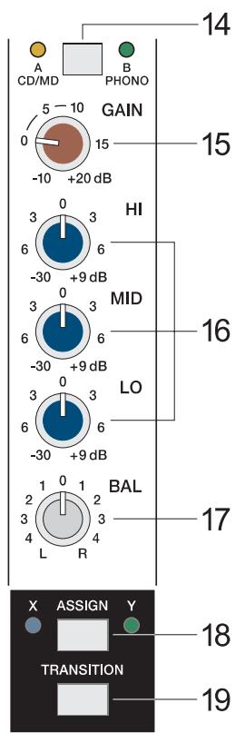
EQ's. Up to turning them to their -6dB marking the tone controls behave analogue to their counterparts in the mono-channels. When turning the controls further, the "Kill"-function becomes active and nearly totally attenuates the corresponding frequency band. The "Kill"-function is meant to be used as special effect providing you with the opportunity to produce mixes that are as creative and entertaining as possible. In this way and when using the MP7 for Karaoke, the MID-control lets you effectively mute the lead vocals of the original recording.
17. BAL
This control lets you determine the proportion between a stereo-channels left and right audio levels. During the playback of pre-recorded music leaving the BAL-control as close as possible to its center position is strongly recommended. Extreme settings for this control should be left for effect purposes only.
TRANSITION SECTION
The TRANSITION FADER in the master section allows conveniently cross-fading between two channels. Assigning each stereo channel to one of the two fader-sides "X" or "Y" is possible via corresponding switches.
18. ASSIGN X/Y
This switch allows assigning the corresponding channel's audio signal to either side "X" or "Y" of the TRANSITION FADER. The two LED's next to the switch indicate the ASSIGN-status (blue = X, green = Y, off = TRANSITION inactive).
19. TRANSITION
This switch allows assigning the corresponding channel to the TRANSITION FADER.
CAUTION: Whenever you want to listen to a channel's audio signal via the master while the corresponding TRANSITION-switch is set to "on", you have to raise the channel fader and slide the TRANSITION FADER to the side, which you have previously selected using the ASSIGN X/Y (18) switch.
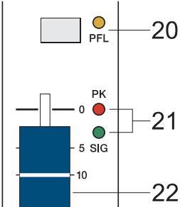
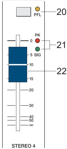
20. PFL
Engaging this button assigns a channel's audio signal to the PFL bus. For monitoring the PFL bus signal via headphones slide the PHONES MIX fader in the direction "PFL". Simultaneously assigning more than one channel to the PFL bus is possible, while the individual channel's volume fader setting is not recognized (PRE FADER LISTEN). This allows you setting a signal's correct level or making special EQ-adjustments without the need of including it in the main mix. Once a PFL button is pressed, the master display automatically enters PFL/PGM mode (yellow LED below the display lights). The right LED-chain indicates the level of the master audio signal (PGM), while the left LED-chain indicates the PFL bus signal level.
21. SIGNAL / PEAK indicator
The Signal / Peak indicator provides optical information of a channel's actual signal level at all times. As already mentioned in the chapter "GAIN", the "signal present" LED should blink in the rhythm of the incoming signal. If this is not the case, increasing the input level using the gain control is necessary. On the other hand, if the PEAK LED lights constantly, the corresponding channel is likely to enter clipping and you have to reduce amplification using the gain control. The "signal present" LED lights at levels 30dB below clipping while the peak LED lights at a level of 8dB below the occurrence of overdrive. To prevent the mixer's input channels from clipping, which for instance may be caused by increasing volumes, keeping an eye on these indicators during operation is a good idea, too. Of course, engaging a channel's PFL-button allows monitoring that channel's level via the display in the master section. Be sure to only engage the PFL-key of the channel that you are about to adjust. The channel's level is displayed in the master display's left LED-chain. Here as well, make sure that the red LED (+12dB) lights only briefly during dynamic peaks.
22.CHANNEL FADER
Stereo Fader for setting the volume of a stereo channel.
Different from the fader function of the MIC input channels, here, the audio signal is not amplified when a channel fader is set to its maximum position. To be sure to use the mixer's entire dynamic capacity, set the CHANNEL FADER during playback to its maximum position.
FX1/FX2
The MP7 employs two completely independent 18-bit stereo effect units - FX1 and FX2. Each unit provides 99 program presets, which are selected by the use of the UP/DOWN buttons. The 99 presets are divided into groups according to their different effect structure, as shown on a printed listing. The programs within each preset group are sorted in ascending order, where higher numbers provide the same FX type with increased intensity. Presets 1 - 20 offer high quality reverberation effect programs that are equally suitable for live performance, recording studio or home recording applications. Program numbers 21 - 40 provide mixed effect types of echo/reverb and chorus/reverb while the numbers 41 - 60 offer different delay effects. The last group from 61 - 99 provides different flanger, chorus, and doubling effects presets as well as special delay and reverb programs. During the initialization of the FX units (when switching on the power of the PowerMate), preset 05 (Large Hall 3 Bright) is selected for the FX1 while the FX2 unit is set to preset 55 (Delay Mono 250ms). These two effects are similarly suitable for live performances and recording applications. This is the factory-preset configuration that can be changed any time. For further information, please refer to the paragraph Changing FX Start Programs.
The two effect programs are equally suitable for live performance or recording applications and can be used separately or together. For testing, evaluating and selecting effect programs, please also refer to the supplementary information form EFFECT PRESETS, which provides detailed description of all effect presets. This listing contains all preset names together with the corresponding effect structure, field of application, and frequency characteristics. Take your time to test all presets and select the ones that are best suited for your specific application. Program number "0" selects a Slap Back Echo, which is mainly for servicing and testing only, and therefore is not included in the effects listing on the front panel.
Changing FX Start Programs
In the factory shipping state, the FX units start with the programs 5/55. If you prefer different programs, you can change and store the new settings in the programming mode. To assign new start programs, please proceed as follows:
- Hold down the two DOWN buttons of FX1 and FX2 simultaneously while switching on the PowerMate.
- "Prog" appears briefly on the display. Programming mode is now active. A software-related side effect is that all buttons behave a bit slower than usual.
- Release the two DOWN buttons and select the desired start programs.
- Press the two UP buttons to store the displayed effect numbers as your new start programs. The FX unit acknowledges the save procedure by briefly indicating "Prog" on the display.
| FX1/FX2 | ||||||
| 1.....10 | 11.....20 | 21.....30 | 31.....40 | 41.....50 | 51.....60 | 61.....99 |
| REVERB HALLS | REVERB PLATES | ECHO REVERB | CHORUS REVERB | DELAY STEREO | DELAY MONO | SPECIAL PROGRAMS |
23. DISPLAY
The display always indicates the actually selected program number for the corresponding FX-unit.
24. UP/DOWN
The UP/DOWN-keys let you step through the effect programs one by one in increasing or declining order. Keeping either one button pressed for a longer period of time allows scrolling the effect program numbers with increased tempo.
25. FX ON
Engaging this switch turns the power of the corresponding internal FX-unit on and the green LED lights. For intelligibility reasons switching the FX-units off during announcements is recommended.
Pushing down the TALK-button while making an announcement from the MIC1-input channel automatically reduces the audio signal's effects portion.
26. PEAK LED
These indicators signal if the input stages of the internal FX-units are driven into clipping. To achieve an adequate S/N-ratio, please adjust the FX units' input level as follows.
Note on how to adjust the FX input signal:
- Establish a "dry" mix - without effect settings - according to the previous descriptions.
- Set the FX-return control (27) of the corresponding effect channel to its center position.
- Use the UP/DOWN Buttons to select the desired FX-program preset.
- Press the FX ON-switch.
- Play the sound source of the desired input channel and adjust the desired amount of the FX-signal, using the FX-controls of the input channel until the resulting effect mix meets your requirements. Repeat this procedure for all input channels that you would like to include in the effect mix.
- Please make sure that the PEAK LED only lights frequently at highly dynamic signal peaks.
- Now, using the FX-return controls lets you alter the percentage of the effect signal in the main mix.
It is good advice to keep an eye on the peak indicators when operating your MP7 to be able to quickly interact when the signal levels exceed the normal range and enter clipping.
27. EFFECT RETURN FX1 / FX2
The setting of these stereo controls determines the amount of the effect signal getting added to the main mix.
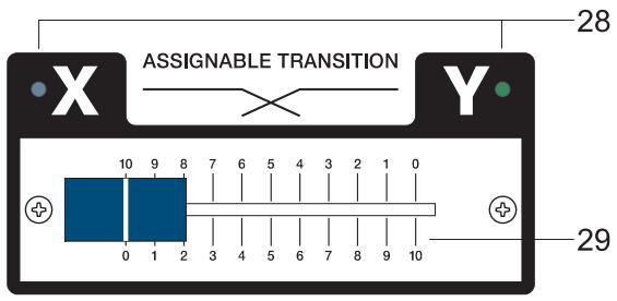
28. X/Y LED
These LED's indicate whether an input channel has been assigned to either side of the TRANSITION FADER (29).
When these LED's are dimmed, the transition function has not been activated for either input channel and the TRANSITION FADER is inactive.
29. ASSIGNABLE TRANSITION
This assignable fader allows comfortably cross-fading between the audio signals of two selected input channels. Please refer to the paragraph TRANSITION SECTION in the chapter INPUT STEREO.
PHONES

PHONES MIX
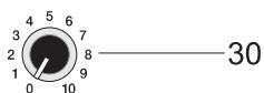
30. PHONES
This control lets you adjust the headphones' volume.
Caution: Depending on the type of headphones connected to the phones jack, the MP7 is capable of producing very high output levels via the phones output. Therefore, make sure to turn the control all the way to the left (minimum setting) before connecting the headphones. Be aware of the fact that listening to loud sound pressure levels over a longer period of time leads to hearing-damage!
31. PHONES MIX
This fader lets you cross-fade the PFL (audio signal sum of all channels with engaged PFL-function) and PGM (the actual master signal) audio signals via headphones.
The fader lets you pre-listen the function of the TRANSITION FADER via headphones.
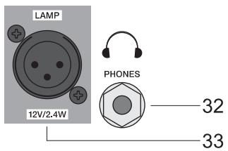
LAMP
12V/2.4W
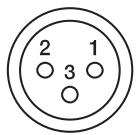
PIN1:SHIELD
PIN2:-12VDC
PIN3: 0VDC
32. PHONES
STEREO phones jack for the connection of headphones with an impedance of 32 - 600 ohms. Two phones connectors are available: one on the controls panel and one on the mixer's front panel.
33. LAMP
XLR-socket for connecting a gooseneck litlite (12VDC / 2.4W max.). Please be sure to painstakingly mind the specifications on the power consumption and pin-assignment of the used lamp. Overload or short-circuit can result in serious damage or failure of the output. If possible, only use the gooseneck litlite (112700), which is available from the DY-NACORD accessory assortment. If in doubt, please consult your local dealer.
34. MASTER B
This control allows setting the output level of the MASTER B, which is a second universal stereo output carrying the stereo-sum audio signal identical to the MASTER A. It is extremely useful in accomplishing sound reinforcement in a neighboring room or monitoring purposes using a second power amplifier. For more details, please refer to the CONFIGURATION EXAMPLES.
35. STEREO/MONO
The MASTER B outputs carry a stereo signal if this switch is set to the STEREO position (not engaged).
When set to MONO (engaged), the MASTER B outputs the sum of the left and right channels.
36. PRE/POST
Setting this switch to PRE (not engaged) lets you control the MASTER B level independent from the level of the MASTER A. When set to POST (engaged), the MASTER B signal is post the MASTER A fader. Changing the level of MASTER A also alters the MASTER B level.
37. MONO OUT
This control lets you set the output level of the MONO OUT connector (40). The MONO OUT outputs the summed audio signal of the left and right channels independent from the setting of the MASTER A Fader (pre fader). The MONO OUT is mostly used for connecting the monitor system or a light control desk.
38. SUB OUT
The SUB OUT represents an output that is especially implemented for connecting a subwoofer via an external power amplifier. The SUB OUT audio signal relates to the MASTER A fader's setting (post fader). It employs an internal 12dB/act, 100Hz low-pass filter. The SUB OUT control lets you set the proportion between subwoofer and general output levels of the system.
CAUTION: In case you would like to connect an active subwoofer to the SUB OUT connector, make sure that it does not incorporate an integrated frequency crossover or if so, that it is deactivated! If this is not possible, you are left with the options of choosing the Mono OUT or MASTER B outputs to accomplish the task.
The SUB OUT audio signal is output via the SUB OUT connector (41).
39. RECORD SEND
These RCA-type connectors carry the MASTER A pre-fader audio signal, which means that the setting of the master fader doesn't affect the level of the audio signal that is present at the RECORD SEND connectors, which let you connect a CD/MD recorder or TAPE/DAT deck. The nominal level of -10dBV at this output is suitable for professional use as well as for home recording purposes.
40. - 43. OUTPUT CONNECTORS
Impedance-balanced outputs for the connection of external gear. The outputs are carried out as stereo phone-type jacks. Whenever possible use balanced cables. Balanced cabling is the best method for avoiding problems with interference and humming (see chapter: Configuration of a standard PA-system)
44. POWER AMP INPUT
Electronically balanced input of the internal power amplifier with signal-split function. Connecting a phone-type plug interrupts the signal path between MASTER A and internal power amp. You can now feed the internal power amplifier from the POWER AMP INPUT. The MASTER A audio signal is still output via the MASTER A OUTPUTS.
45. STATUS INDICATORS
These LED's provide information about the actual operational status of the MP7's internal power amplifiers.
POWER ON lights whenever the MP7's power is set to ON. If, after switching the MP7 on, the LED does not light, the first thing to do is to make sure that the mains plug is plugged in correctly. If that is the case and the LED still stays dimmed, please contact your dealer.
The LIMIT indicator signals that the MP7's internal power amplifiers are actually operated at their limits. Frequent blinking of the LED is acceptable, since the amplifiers' incorporated limiters prevent the occurrence of distortion. Continuous lighting indicates that degradation in the outputted sound is likely to happen. In that case, reducing the master level is recommended.
The PROTECT indicator lights when one of the power amplifiers' extensive protection functions - against thermal overload, HF-induction, DC at the outputs, and SOAR-protection - is activated. When the MP7 is in protect mode, the speaker outputs are muted and the inputs of the power amplifier are short-circuited to prevent the amplifiers from being damaged. In this case you should first check if the frontal and/or rear ventilation louvers are blocked. Another cause for the activation of the protect functions might be, that you have connected more than three 8ohms speaker systems per power output. Please also disconnect the SPEAKON connectors and check the speaker cables for short circuit. During the power-on operation, the PROTECT LED always lights for about two seconds. This is normal. It indicates that the MP7's protection circuitry is operational.
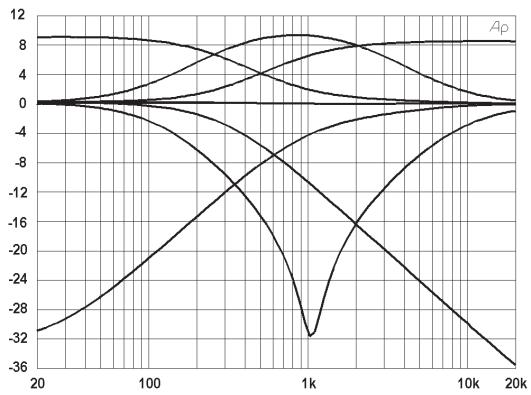
The MP7's integrated, switchable 7-Band Stereo Graphic Equalizer is located in the L/R master channel section. The seven frequency bands - each providing ± 10dB amplification/attenuation - offer the possibility to optimally match the overall sound to the acoustic conditions of different locations or shape it according to your personal taste.

The frequency ranges as well as the characteristics of the EQ-faders are designed to meet your day-in-day-out requirements. In case you intend to have a clear and highly intelligible sound, you might want to increase the level setting of the 8kHz or 16kHz band a bit. If the mid-range sounds a bit nasal, try attenuating the mid-band by some decibels. If you like to provide your sound with more bass, you have to boost the low frequency range, using the 80Hz or the 250Hz controls. On the other hand, if the overall sound is undefined with too much bass, lowering the levels of these two frequency bands will solve the problem. Especially when using the equalizer, being aware of the fact that in most cases less can be more is good advice.
47. EQ ON/OFF
This switch activates or deactivates (ON / OFF) the integrated 7-BAND-EQUALIZER.
48. MASTER DISPLAY
The MASTER DISPLAY offers two modes. The PFL/PGM LED (49) indicates which one is actually selected:
a) MASTER A Level: LED (49) is dimmed. The two LED-chains indicate the audio level that is output via the MASTER A OUTPUTS L and R in dBu.
b) PFL/PGM Split: LED (49) lights. This mode is automatically activated when pressing a PFL-button. The left LED-chain indicates the PFL-bus level while the right LED-chain indicates the audio level of the master sum. (please also refer to the chapter INPUT STEREO)
49. PFL/PGM SPLIT LED
Indicates the master display mode.
50. BAL
This control is for determine the ration of the levels of the left and right MASTER A output channels. During music playback, it is recommended to leave the BAL-control at its center position whenever possible. In most cases, extreme settings are only useful for effect purposes.
51. MASTER A FADER
Stereo fader for adjusting the overall volume as well as the output level of the internal power amplifiers and the MASTER A OUTPUTS.
Please, make sure to close the fader of the corresponding input channel or at least the MASTER controls before connecting any audio signal sources. This will save yourself, your audience, and your equipment from unnecessary stress resulting from plug-in noise.
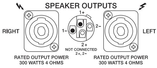
The MP7 provides professional SPEAKON-type high-performance connectors, which offer mechanically and electric secure connection that complies with any safety standards. Additionally, SPEAKON-type connectors allow utilizing high-performance loudspeaker cables with diameters of up to 4 × 2.5 ~mm^2 .
Single plugs and jacks as well as high-performance speaker cables are available from the DYNACORD accessory assortment.
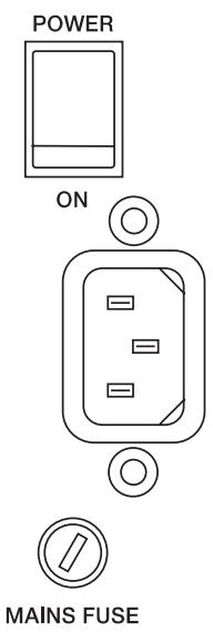

POWER
Mains switch for switching the MP7's power ON or OFF. The appliance is operational when the POWER ON-LED lights and the power relays have switched the power amplifier output signal to the speaker outputs.
Before switching the mixer's power on, make sure to set the master faders to their minimum position. This will save yourself, your audience, and your equipment from unnecessary stress resulting from switching or feedback noise.
When switching your audio system on with additional power amplifiers or other electronic equipment, like for example CD-Players, MD-Recorders, etc. connected, please proceed in the following sequence:
- switch the CD-Player's power on
- switch the MP7's power on
- switch the additionally connected gear (power amps) on
Please proceed in the opposite sequence when switching the audio system off.
PHONO GROUND
Facility for connecting the chassis ground of a turntable. Make sure to connect the chassis ground to the PHONO GROUND screw. Otherwise you might be facing hum and interference noise.
CABLING
The mains cord is supplied with your MP7. The quality of all other cables is left to your responsibility. Carefully chosen high quality cables are the best precaution to prevent problems from occurring during the later operation. In the following we would like to provide you with some recommendations for the trouble-free operation of your setup.
SPEAKER CABLES
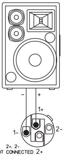
Our experience as a manufacturer of loudspeaker systems has taught us that flexible cables with a rubber jacket and a diameter of 2.5mm^2 per conductor, used in combination with SPEAKON plugs and sockets, are the best choice to guarantee the optimal connection of loudspeaker systems. The connection of the SPEAKON plugs to the corresponding connectors on the MP7's rear panel has to be in accordance to the corresponding diagram below. We recommend the use 4-wire cables where also the pins 2+ and 2- are connected through. This provides you with the possibility to use these cables in an active 2-way system configuration, as well. DYNACORD speaker cables with SPEAKON connectors and all other cables, plugs, and sockets are available at your professional audio dealer.
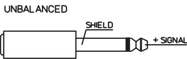
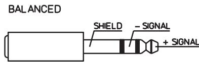
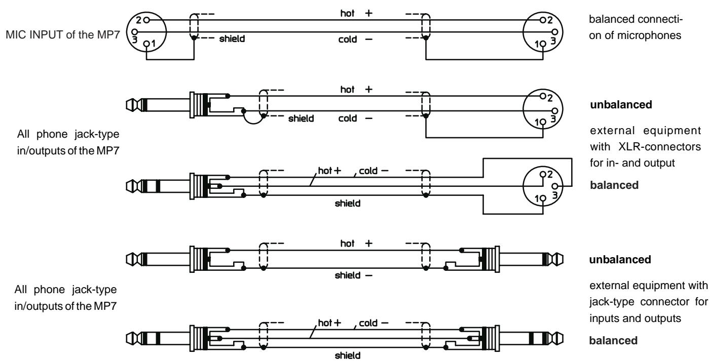
LF-CABLES-BALANCED OR UNBALANCED?
For LF-cabling – all the low current wiring – your best choice are balanced cables (2 signal conductors + ground shielding) with XLR-type connectors or stereo phone jacks and plugs. The cables should be step proof, shielded, and never longer than absolutely necessary. Too many too long cables mostly lead to confusion and generate unnecessary problems.
Of course, you can also connect unbalanced cables with monaural phone plugs to the MP7's in- and outputs and because of its superb grounding managing system, in most cases no interference will occur. Still, there is a minimal risk that problems could arise. Generally spoken, if you have the choice, balanced LF-cables are always the better solution and they should be preferred. Today's modern audio equipment – like amplifiers, equalizers, FX units, mixing consoles, and even some keyboards – offers balanced in- and outputs. In a balanced signal path, the cable screen provides a gapless connection of all metal parts, offering efficient shielding against the induction of external noise.
The balanced cabling in conjunction with the common-mode rejection of the MP7's input stage effectively eliminates even existing artifacts of interference. All inputs of the MP7 provide balanced audio connections and high common-mode rejection. The mixing stage outputs - MASTER B, MOMO OUT, etc. - are laid out in GND-SENSING technology - a special, impedance-balanced pin assignment of the output jacks, offering all advantages of the balanced signal transmission, but lets you also connect monaural phone plugs, without a problem. Nevertheless - as mentioned above - when longer cables are involved, using stereo phone plugs and balanced cables are the better alternative. The diagrams below show the pin assignments of plugs and cables like they can be used with the MP7.
In the following we will explain how to set up a standard PA-system with monitoring facility using the MP7.
The equipment list includes:
1 MP7
2 Hi-range speaker system cabinets, e.g. CP 12-2
2 Bass speaker system cabinets e.g. CP 12-1
2 Loudspeaker pole-mount stands or 2 intermediate poles
2 Speakon cables, 8m
2 Speakon cables, 2m
1 AM12 active monitor system
1 LF-cable with stereo phone plugs
Setting up
Look for the most suitable location to set up the loudspeaker systems. Whenever possible, place the bass cabinets on the floor and the Hi-range cabinets directly on top. However, in doing so, make sure that the hi-range cabinets' lower edge is in the same height of the audience's heads or above. You can either use intermediate poles between the bass and Hi-range cabinets or, if this does not provide enough elevation for the speaker systems or there are no bass cabinets included, use appropriate speaker pole-mount stands.
Compact overall sound is achieved by placing the left and right loudspeakers as far apart from each other as necessary but as close together as possible.
Make sure that the main speakers are not behind you. Otherwise you will be facing feedback whenever your system set-up includes microphones or turntables.
Use SPEAKON-type cables to establish connections between the loudspeaker systems and the MP7. Follow the instructions as shown in figure1. Make sure not to inadvertently reverse connect the left and right channels. The short SPEAKON-type cables are used to parallel connect Hi-range and Bass cabinets.
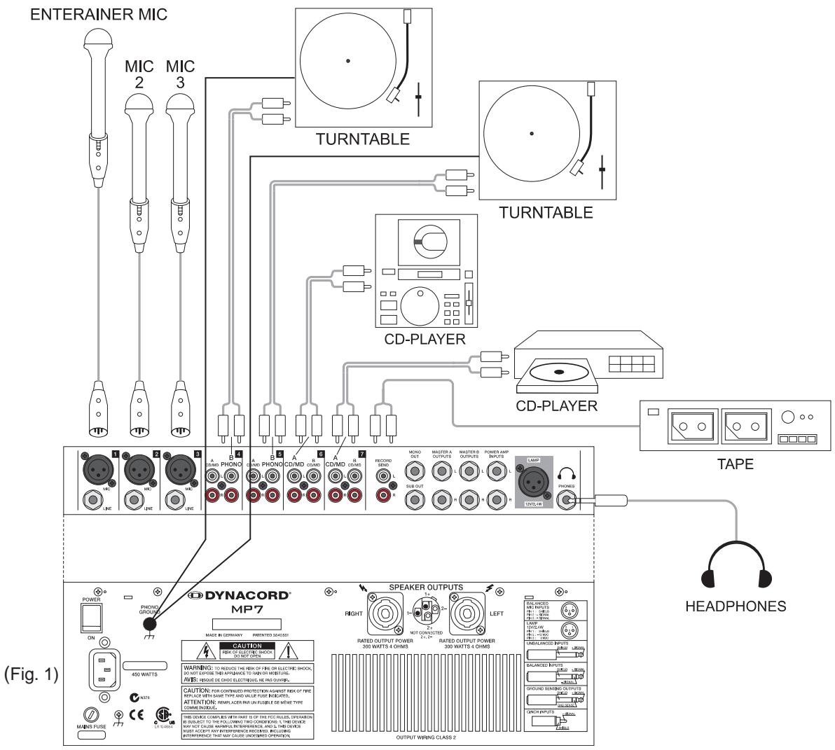
Place the needed sound source devices (e.g. CD-Player, turntable) or microphones on a secure even location and, if necessary, establish mains connections
Connect all the gear to the MP7 (Fig. 2).
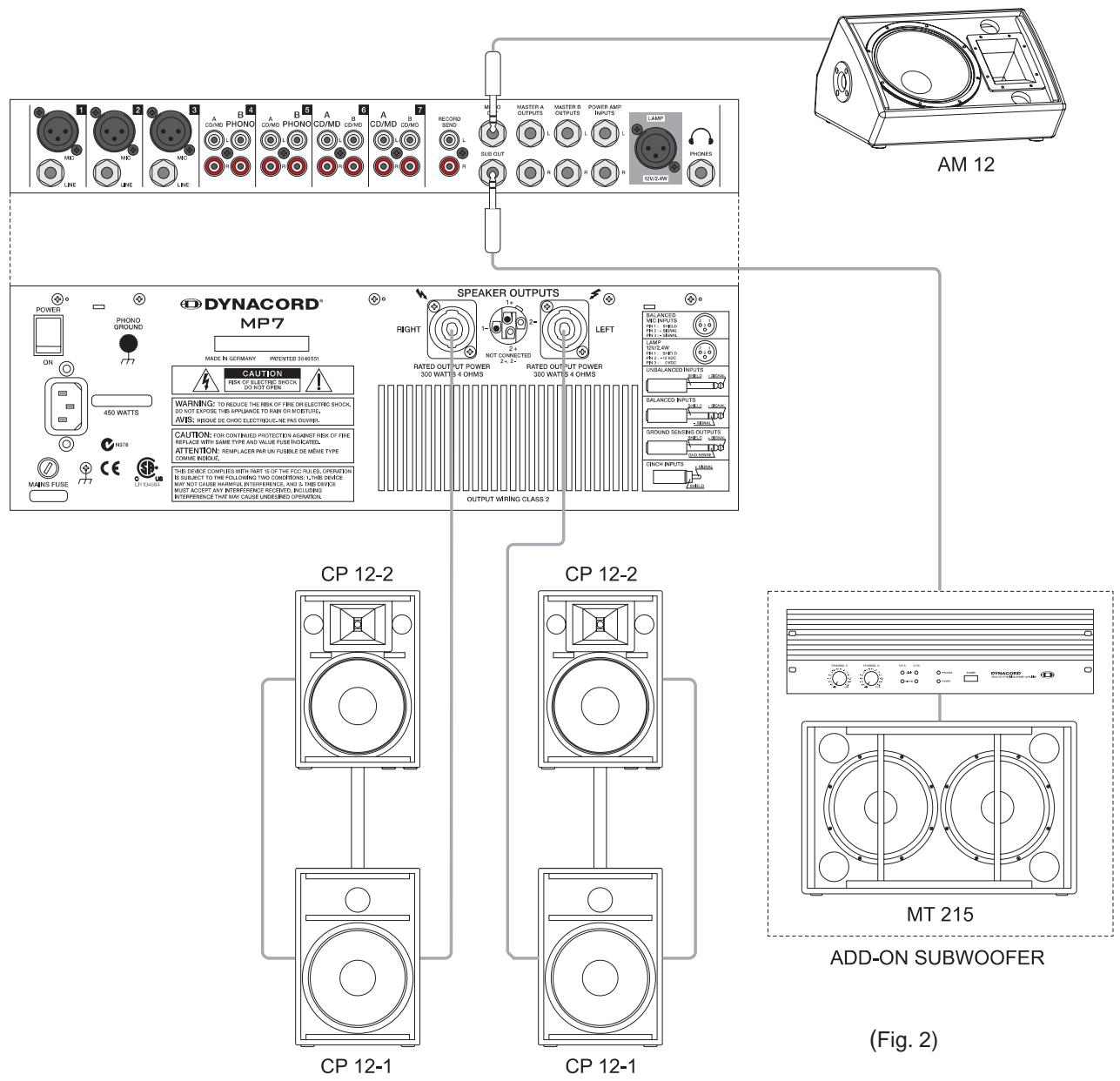
Employ cables with stereo phone-type plugs to connect the AM12 to the MONO OUT of the MP7. Set the LINE IN-control on the AM12 at its center position. This lets you control the AM12's volume setting from the MONO OUT-control on the MP7.
Set all faders on the MP7 at their minimum position and turn all output controls (e.g. MONO OUT) counterclockwise as far as possible. Switch on the power of all included components in the following sequence:
- Sound source equipment, e.g. CD-Player, turntable, etc.
- MP7
- AM12 active monitors
Following this order when switching on your system prevents unpleasant power-on noise and feedback. Your PA-system is now ready for operation!
When operating the MP7 be sure to mind the following notes:
- A red LED next to the meter instruments that is constantly lit signals that the corresponding channel is on the verge of clipping! Use the Gain-control of the corresponding channel to reduce the audio signal level until the red LED lights only during program peaks.
- Avoid extreme output levels. The MP7 is no "HiFi-toy"!
Employing high-quality, high-performance PA-speaker systems, like the CP12-1 and CP12-2, allows sound reproduction at extreme high sound pressure levels, which bares the risk of resulting hearing damage. The same is true for the headphones output. Do not expose your ears to high sound pressure levels over an extended period of time. The use of closed DJ-type headphones provides improved shielding against outer noise and is therefore strongly recommended. Using these types of headphones automatically leads to reducing the sound level settings.
- The Master-EQ is primarily aimed for making minor corrections in the overall sound only. Employing high-quality loudspeaker systems is the best guarantee for a perfect sound, even with the Master-EQ being deactivated.
- Make sure to carefully test all components of the entire system prior to a live-performance. Test the system set to the output level, which you are going to use during the later performance.
This is the only way to ensure that you are not facing feedback or other problems with the connected gear resulting from vibration, shock or other sources during the later performance.
5. However, it is good advice to check the system's overall sound quality as well as the volume setting during a performance and make corrections, if necessary.
Example 1: Extending your system with an add-on subwoofer for more bass pressure is displayed in fig. 1.
Ask your local dealer before extending your system!
Example 2: In Fig. 3 you can see how to control larger PA-Systems with your MP7. Simply connect the MASTER A outputs with the external system amplifier and the MASTER B outputs with the POWER AMP INPUTS of the MP7.
The volume of the Main-PA is controlled by the master fader, like before. MASTER B drives the internal amplifiers and provides a full-stereo monitoring via two additional monitor cabinets.
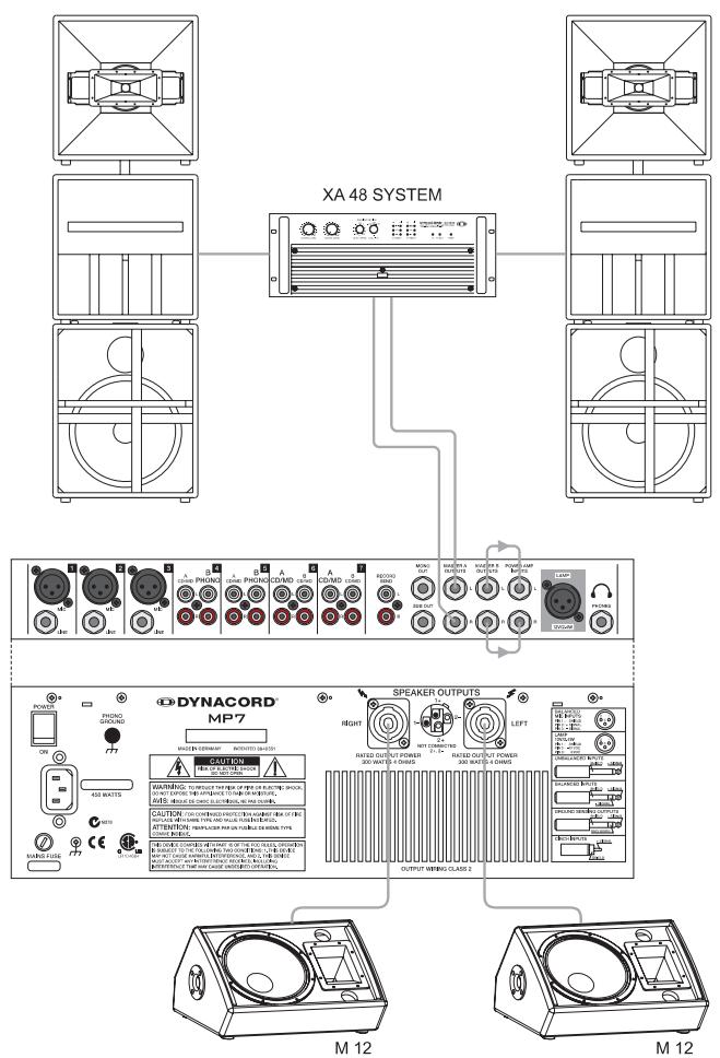
(Fig. 3)
2 x 300 W STEREO MONITORING
IMPORTANT INFORMATIONS DE SECURITÉ
49. LED PFL/PGM SPLIT
Technical Specifications MP7 Mixing desk in rated condition. Unity Gain (MIC Gain 20 dB), all faders position 0 dB, all pots in mid position, master fader + 6dB, amplifier rated output power into 8 ohms, one channel driven, unless otherwise specified.
Maximum Midband Output Power, 1kHz THD = 1%
into 4 ohms 2 × 340 ~W
into 8 ohms 2 × 200 ~W
Rated Output Power, 20Hz... 20 kHz, THD =0.2%
into 4 ohms 2 × 300 ~W
into 8 ohms 2 × 150 ~W
Maximum Output Voltage of the power amplifier, no load 43 Vrms
THD @ 1 kHz, MBW=80kHz
MIC input to Main L/R output, +16 dBu < 0.006%
Power amplifier input to speaker L/R output < 0.08%
DIM 30, power amplifier < 0.03%
IMD-SMPTE, power amplifier, 60Hz, 7 kHz < 0.2%
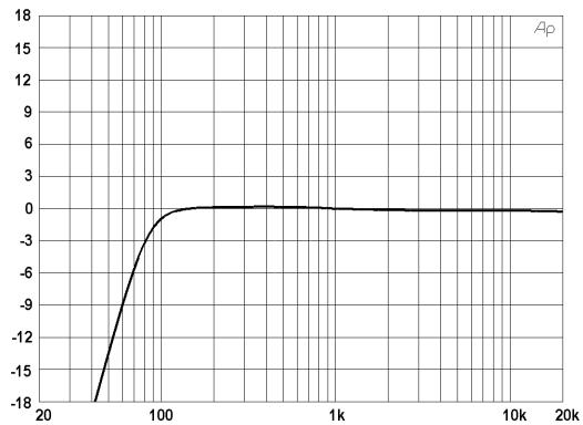
Frequency Response, -3dB ref. 1 kHz
Any input to any mixer output 15Hz...60kHz
Any input to speaker output L/R 30Hz...40kHz
Crosstalk, 1 kHz
Fader attenuation >90 dB
Channel seperation >70 dB
Input Sensitivity, all level controls in max. position
MIC input -74 dBu (155μV)
Line Input (Mono) -54 dBu (1.55 mV)
CD/MD Line Input (Stereo) -24 dBu (49 mV)
Phone Input (Stereo) -61.5 dBu (652 V)
Power Amplifier Input +6 dBu (1.55 V)
Maximum Level, mixing desk
MIC inputs +11 dBu
Line inputs +30dBu
All other inputs +20dBu
Record Send output +14 dBu
All other outputs +20dBu
Input Impedances
MIC 1.8 kohms
All other inputs >10 kohms
Output Impedances
Record Send 1 kohms
Phone 47 ohms
All other outputs 75 ohms
Equivalent Input Noise, MIC Input, A-weighted 150 ohms
Noise, Channel inputs to Main L/R outputs, A-weighted
Master fader down -104 dBu
Master fader 0 dB, Channel fader down -91 dBu
Master fader 0 dB, Channel fader 0 dB, Channel gain unity -84 dBu
Signal/Noise-Ratio, power amplifier, A-weighted 105 dB
Equalization STEREO
LO Shelving +9 / - 30 dB/60 Hz
MID Peaking +9/-30 dB / 2.4 kHz
HI Shelving +9 / - 30 dB/12 kHz
Equalization MIC
LO Shelving ±15 dB / 60 Hz
MID Peaking ±12 dB / 2.4 kHz
HI Shelving ±15 dB / 12 kHz
Master EQ, 2x7-band, Stereo ±10 dB
Phantom Power, all MIC Inputs +24V dc
Lamp +12V dc
Power Requirements, factory preset, 50Hz....60Hz 100V/120V/230V/240V
Power Consumption at 1/8 maximum output power 4 ohms 450 W
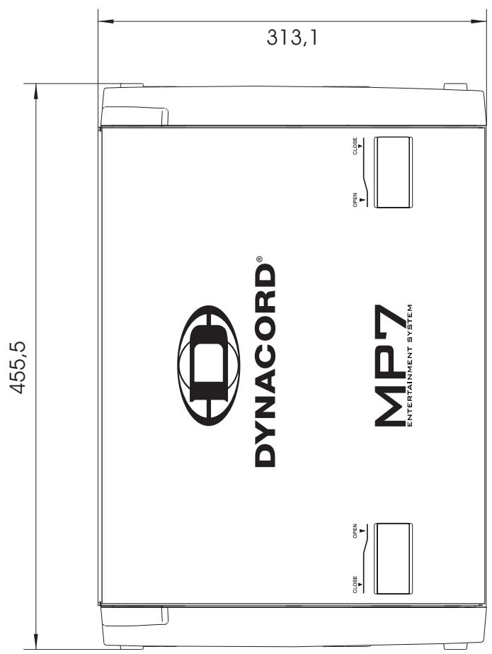
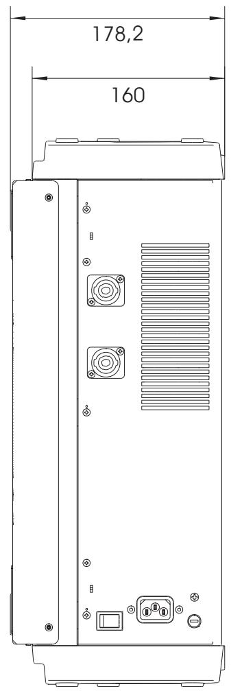
Dimensions, (WxHxD), mm 455,5 x 175,8 x 340.6
Weight, including lid 13 kg
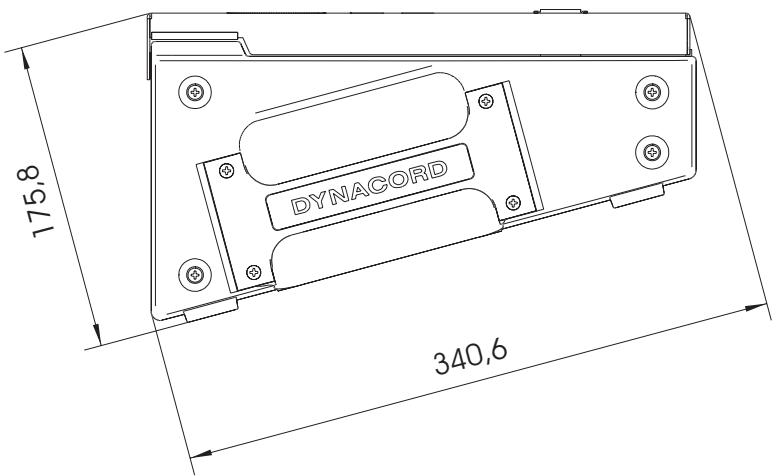
Optional Rack-Mount-Kit MP7 (NRS 90259) 112844
Wall-Mount-Kit MP7 (NRS 90242) 112742
Transition Fader MP7 (NRS 90261) 112853
Abmessungen/Dimensions (in mm)
GARANTIE
The manufacturer's warranty covers all substantial defects in materials and workmanship for a period of 36 months from the date of purchase.
Liability claims are accepted solely, when a valid - correctly and completely filled out - Warranty Registration form is presented by the original owner of the product. The warranty does not cover damage that results from improper or inadequate treatment or maintenance. In case of alteration or unauthorized repairs, the warranty is automatically terminated.
GARANTIE
- PFL/PGM SPLIT LED
- IMPORTANT SAFETY INSTRUCTIONS
- CAUTION
- For US, CANADA and Japan only:
- IMPORTANT SERVICE INSTRUCTIONS
- CONTENTS
- Congratulations!
- Unpacking and Warranty
- Installation and Connections
- MIC
- LINE
- LO CUT 80Hz
- GAIN
- EQ SECTION
- PAN
- FX1/2
- MUTE
- PFL
- SIGNAL / PEAK indicator
- VOLUME
- TALK
- STEREO INPUT
- INPUT SELECT
- GAIN
- TONE CONTROL
- BAL
- TRANSITION SECTION
- ASSIGN X/Y
- TRANSITION
- PFL
- SIGNAL / PEAK indicator
- 22.CHANNEL FADER
- FX1/FX2
- Changing FX Start Programs
- DISPLAY
- UP/DOWN
- FX ON
- PEAK LED
- Note on how to adjust the FX input signal:
- EFFECT RETURN FX1 / FX2
- X/Y LED
- ASSIGNABLE TRANSITION
- PHONES
- PHONES MIX
- LAMP
- PHONES
- LAMP
- MASTER B
- STEREO/MONO
- PRE/POST
- MONO OUT
- SUB OUT
- RECORD SEND
- - 43. OUTPUT CONNECTORS
- POWER AMP INPUT
- STATUS INDICATORS
- EQ ON/OFF
- MASTER DISPLAY
- BAL
- MASTER A FADER
- POWER
- PHONO GROUND
- CABLING
- SPEAKER CABLES
- LF-CABLES-BALANCED OR UNBALANCED?
- Setting up
- When operating the MP7 be sure to mind the following notes:
- Ask your local dealer before extending your system!
- IMPORTANT INFORMATIONS DE SECURITÉ
- LED PFL/PGM SPLIT
- GARANTIE
Brand : DYNACORD
Model : MP7
Category : Mixer