CL 2000 - Power amplifier DYNACORD - Free user manual and instructions
Find the device manual for free CL 2000 DYNACORD in PDF.
| Product type | Power amplifier |
| Brand | DYNACORD |
| Model | CL 2000 |
| Output power (stereo) | 2 x 600 W at 8 Ω, 2 x 1000 W at 4 Ω, 2 x 1500 W at 2 Ω |
| Output power (bridged mono) | 3000 W at 4 Ω |
| Voltage gain | 32 dB |
| Input sensitivity | +5.5 dBu (1.46 V) |
| Input impedance | Balanced: 20 kΩ |
| Mains power supply | 230 V (adjustable 100-240 V via internal selector) |
| Power consumption | Up to 5255 W at maximum load (sine 2 Ω) |
| Input connectors | Female XLR (electronically balanced) |
| Output connectors | Speakon (CH A, CH B, BRIDGED OUT) |
| Link connectors | Male XLR (direct output of input signal) |
| Cooling | Front to rear, 3-speed fans |
| Built-in protection | Thermal, short circuit, HF, DC, back EMF, dynamic limiter |
| Features | Soft-start, delay relay, Dual/Parallel/Bridged mode, Ground-Lift, detented potentiometers |
| LED indicators | Power, Protect, Signal, 0 dB, Limit |
| Cleaning | Dry cloth only |
| Operating ambient temperature | 0 °C to +40 °C |
| Weight | Approximately 22 kg (estimate) |
| Dimensions (W x H x D) | 483 x 88 x 420 mm (estimate, 19", 2U) |
Frequently Asked Questions - CL 2000 DYNACORD
User questions about CL 2000 DYNACORD
0 question about this device. Answer the ones you know or ask your own.
Ask a new question about this device
Download the instructions for your Power amplifier in PDF format for free! Find your manual CL 2000 - DYNACORD and take your electronic device back in hand. On this page are published all the documents necessary for the use of your device. CL 2000 by DYNACORD.
USER MANUAL CL 2000 DYNACORD
IMPORTANT SAFETY INSTRUCTIONS 3
IMPORTANT SERVICE INSTRUCTIONS 3
DESCRIPTION 4
UNPACKING & WARRANTY 5
INSTALLATION NOTES 5
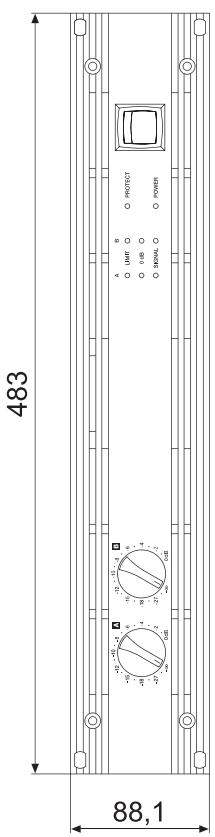
FRONT VIEW 6
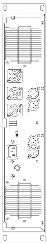
REAR VIEW 7
INPUT A / INPUT B
PARALLEL 7
POWER AMP OUTPUT 8
BRIDGED MODE 8
GROUND-LIFT SWITCH 8
MAINS INPUT 8
SPECIFICATIONS 31
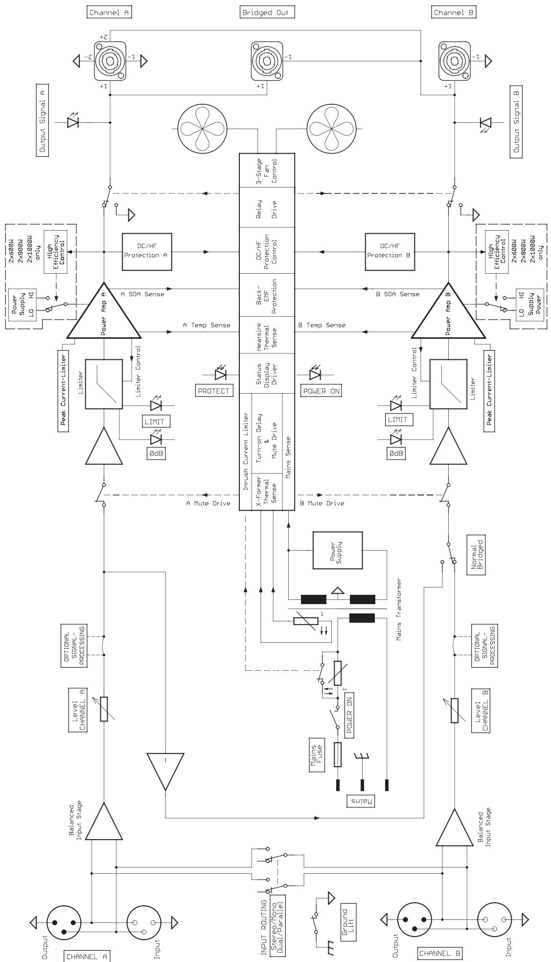
BLOCKDIAGRAM 32
DIMENSIONS 33
INHALT
IMPORTANT SAFETY INSTRUCTIONS

CAUTION
RISK OF ELECTRIC SHOCK DO NOT OPEN

WARNING: TO REDUCE THE RISK OF FIRE OR ELECTRIC SHOCK, DO NOT EXPOSE THIS APPLIANCE TO RAIN OR MOISTURE.
AVIS: RISQUÉ DE CHOC ELECTRIQUE. NE PAS OUVRIR.
WARNING: CONNECT ONLY TO MAINS SOCKET WITH PROTECTIVE EARTHING CONNECTION.
The lightning flash with arrowhead symbol, within an equilateral triangle is intended to alert the user to the presence of uninsulated "dangerous voltage" within the product's enclosure that may be of sufficient magnitude to constitute a risk of electric shock to persons.

The exclamation point within an equilateral triangle is intended to alert the user to the presence of important operating and maintenance (servicing) instructions in the literature accompanying the appliance.
- Read these instructions.
- Keep these instructions.
- Heed all warnings.
- Follow all instructions.
- Do not use this apparatus near water.
- Clean only with a dry cloth.
- Do not block any ventilation openings. Install in accordance with the manufacture's instructions.
- Do not install near heat sources such as radiators, heat registers, stoves, or other apparatus (including amplifiers) that produce heat.
- Do not defeat the safety purpose of the polarized or the grounding-type plug. A polarized plug has two blades with one wider than the other. A grounding type plug has two blades and a third grounding prong. The wide blade or the third prong are provided for your safety. If the provided plug does not fit into your outlet, consult an electrician for replacement of the obsolete outlet.
- Protect the power cord from being walked on or pinched particularly at plugs, convenience receptacles, and the point where they exit from the apparatus.
- Only use attachments/accessories specified by the manufacturer.
- Use only with the cart, tripod, bracket, or table specified by the manufacturer, or sold with the apparatus. When a cart is used, use caution when moving the cart/apparatus combination to avoid injury from tip-over.

- Unplug this apparatus during lightning storms or when unused for a long period of time.
Refer all servicing to qualified service personnel. Servicing is required when the apparatus has been damaged in any way, such as power-supply cord or plug is damaged, liquid has been spilled or objects have fallen into the apparatus, the apparatus has been exposed to rain or moisture, does not operate normally, or has been dropped. - Do not expose this equipment to dripping or splashing and ensure that no objects filled with liquids, such as vases, are placed on the equipment.
- To completely disconnect this equipment from the AC Mains, disconnect the power plug from the AC receptacle.
- The mains plug of the power supply cord shall remain readily operable.

Management of WEEE (waste electrical and electronic equipment) (applicable in Member States of the European Union and other European countries with individual national policies on the management of WEEE) The symbol on the product or on its packaging indicates that this product may not be treated as regular household waste, but has to be disposed through returning it at a Telex dealer.
IMPORTANT SERVICE INSTRUCTIONS
CAUTION:
These servicing instructions are for use by qualified personnel only. To reduce the risk of electric shock, do not perform any servicing other than that contained in the Operating Instructions unless you are qualified to do so. Refer all servicing to qualified service personnel.
- Security regulations as stated in the EN 60065 (VDE 0860 / IEC 65) and the CSA E65 - 94 have to be obeyed when servicing the appliance.
- Use of a mains separator transformer is mandatory during maintenance while the appliance is opened, needs to be operated and is connected to the mains.
- Switch off the power before retrofitting any extensions, changing the mains voltage or the output voltage.
- The minimum distance between parts carrying mains voltage and any accessible metal piece (metal enclosure), respectively between the mains poles has to be 3mm and needs to be minded at all times. The minimum distance between parts carrying mains voltage and any switches or breakers that are not connected to the mains (secondary parts) has to be 6mm and needs to be minded at all times.
- Replacing special components that are marked in the circuit diagram using the security symbol (Note) is only permissible when using original parts.
- Altering the circuitry without prior consent or advice is not legitimate.
- Any work security regulations that are applicable at the location where the appliance is being serviced have to be strictly obeyed. This applies also to any regulations about the work place itself.
- All instructions concerning the handling of MOS - circuits have to be observed.
NOTE:

SAFETY COMPONENT ( MUST BE REPLACED BY ORIGINAL PART )
Congratulations! With buying a DYNACORD CL-SERIES power amplifier you have chosen an appliance that employs most advanced technology.
CL-Series power amps combine outstanding audio performance, highest reliability and operational safety.
The audio performance of CL power amps are simply extraordinary. Optimised power supply units employing low-leakage toroidal transformers and the consistent use of Class-H technology provide extensive headroom far above the stated nominal output. At the same time this contributes to a reduction in weight and power dissipation.
The CL1200/1600/2000 is designed in Class-H technology, i.e. the power amp provides extremely fast, signal-dependent operating voltage switching, which results in doubling the regular supply voltage when needed. Compared to Class-AB power amps, Class-H power amps generate by far less power dissipation at identical output. Consequently, reduced leakage power or dissipation is synonymous to less waste heat – energy is used more efficiently. As a result, installing Class-H power amps within rack shelf systems is possible with less space between appliances. In addition to that and despite offering identical output, power consumption is a lot less than in Class-AB operation.
DYNACORD CL-SERIES power amps have been designed to fulfil even the most demanding requirements of touring applications. CL-Series amps are protected against thermal and electrical overload, short circuit and the occurrence of HF/DC at the outputs. Back-EMF-Protection eliminates the risk of the output transistors being damaged by electrical energy back-feed. The power outputs are switched via relay with a time delay during soft-start. An inrush current limiter prevents mains fuses from blowing.
Mechanical construction and workmanship also comply with the highest precision manufacturing standards. The rigid sheet steel chassis even resists the most wearing tour operation. Two three-speed high performance fans (off/slow/fast) guarantee outstanding thermal stability at absolute low running noise. The ventilation is directed front-to-rear allowing trouble-free operation even in smaller amp-racks. The electronically balanced inputs are carried out via XLR-type connectors. Direct-Outs for through connecting the audio signal are also provided via XLRM-type connectors. Input Routing allows selecting DUAL (stereo) or PARALLEL (monaural) operation mode. By means of the separate BRIDGED OUT-connector and a Bridged Mode-switch, switching to „Mono Bridged" operation is truly uncomplicated as well. The recessed mounted dB-scaled level controls ensure reliable protection against mechanical damage. These particularly precise, secure to operate detent-potentiometers are located on the front panel. CL-Series power amps provide the opportunity for retrofitting an internal analogue signal processor board with x-over and filter functions.
The easily readable LED display provides a quick overview of the power amp's current operational status. The power outputs CHANNEL A, CHANNEL B and BRIDGED OUT are carried out as extremely durable SPEAKON-type connectors. Also located on the rear panel is a Ground-lift switch, which helps eliminating ground-noise loops by separating the power amp's enclosure from the circuit ground. In normal operation, all CL-Series power amps are capable of driving loads as low as 2ohms. In Mono-Bridged mode the allowable minimum load is 4ohms.
This owner's manual outlines and explains several other features of your CL-Series power amplifier.
Please, make sure to carefully read all of it and mind the instructions.
UNPACKING & WARRANTY
Carefully open the packaging and take out the power amplifier. Next to the power amplifier itself, the package also includes this owner's manual, a mains cord and the warranty certificate. Keep the original invoice, which states the purchase/delivery date together with the warranty certificate at a safe place.
INSTALLATION NOTES
Generally, installing or mounting power amps should be carried out in a way that guarantees continuously unopposed front-to-rear air circulation. Installation of appliances with opposite air circulation within one cabinet or closed rack shelf system is not recommended. When including an appliance in a closed cabinet or rack shelf system make sure to provide sufficient ventilation. Leave a gap of at least 60mm x 330mm (up to the cabinet's top ventilation louvers) for air circulation between the rear of the power amplifier and the cabinet's/rack's rear inner wall. Make sure to leave at least 100mm of space above the cabinet or rack shelf system. Since temperatures inside of the cabinet or rack shelf system can easily rise up to 40^ during operation, bearing in mind the maximally allowable environmental temperature during operation for all other appliances installed in the same rack shelf system is mandatory (also refer to "MAINS OPERATION AND RESULTING TEMPERATURE").
Caution: For trouble-free operation exceeding the maximally allowable environmental temperature of +40^ is not permissible.
The use of installation rails or optionally available "rear-rack-mount" rails is strongly recommended when installing the appliance in a rack shelf system or cabinet to prevent the front panel from bending.
The power amplifier has to be protected against: dripping or splashing water, direct sunlight, high temperatures or direct influence of heat sources, high humidity, extensive dust and vibrations.
Condensation on internal parts may occur when transporting the power amplifier from a cold into a warmer environment. In that case operation is only permissible after the appliance has gained the new temperature (after approximately one hour). If foreign objects or liquids have entered the power amplifier's enclosure make sure to instantly separate the appliance from the mains power and contact an authorised service centre for inspection before continuing operation.
Use the POWER switch, located on the front panel's, right side to switch the appliance's power on. The soft-start function limits against current inrush peaks on the mains, which in addition prevents the mains line protection switch from activating during power-on. The loudspeaker outputs are activated via relay switching with a delay of approximately 2 seconds to efficiently attenuate eventual power-on noise. The PROTECT LED lights during the delay time and the fans run at maximum speed. This is normal, confirming the correct operation of the protection circuitry.

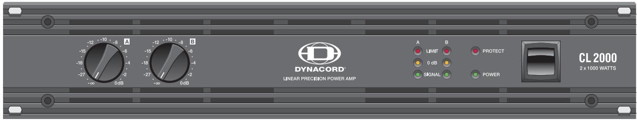
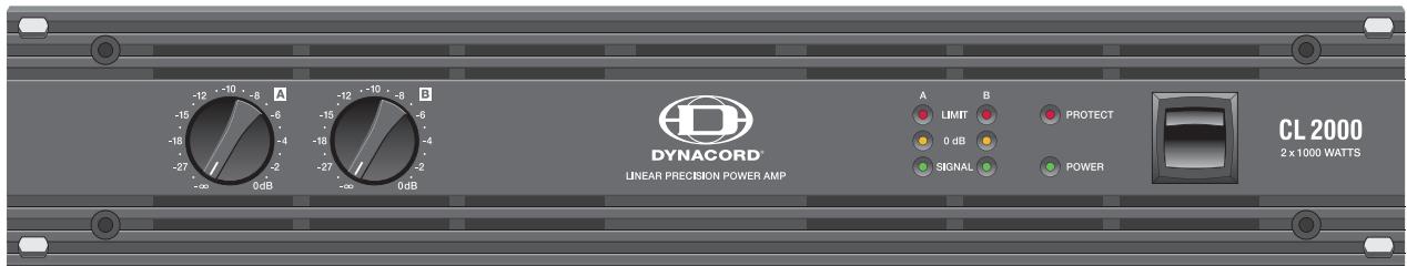
POWER
This indicator lights when the power amplifier has been switched on. Causes for the POWER-indicator not lighting are: the appliance is not connected to the mains or the primary fuse is defective.

PROTECT
The PROTECT LED indicating that one of the internal protection circuits against thermal overload, short-circuit, Back-EMF, RF-occurrence at the output, etc., has been activated. The output relays interrupt the connected loads from the power amps while input signals are interrupted as well, preventing the connected loudspeaker systems and the power amplifiers themselves from being damaged. Whatever caused the fault – e.g. a short-circuited speaker cable – needs to be remedied. In case of thermal overload you have to wait until the power amplifier automatically regains normal operation.

SIGNAL
The SIGNAL LED lights as soon as an audio signal of approximately 30dB below full modulation is present at the output. The LED is dimmed when speaker cables are short-circuited or a protection circuit has been activated.

0 dB

The 0dB LED lights whenever the power amplifier is driven at its maximum. Higher input voltage does not result in higher peak output voltage. In addition, the 0dB indicator comes in handy when adjusting external limiters.

LIMIT

This indicator lights as soon as the integrated dynamic audio signal limiter is activated and the power amplifier is driven at the clipping limit or generally at its maximum capacity. Short-term blinking is not a problem, because the internal limiter controls input levels of up to +21dBu down to a THD of approximately 1% . If, on the other hand, this LED lights constantly, reducing the volume is recommended to prevent the loudspeaker systems connected from being damaged by probable overload.
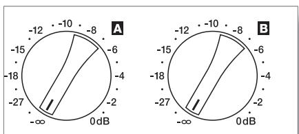
Detent potentiometers scaled in dB (steps of 1dB) for adjusting the power amp's overall volume. To prevent distortion in mixing consoles connected to your CL-Series amp, setting these controls to a value between 0dB and -6dB is generally recommended. The dB-scale provides direct indication of the control attenuation applied to the fixed internal amplification.
INPUT A / INPUT B
| CL800 +1.15dBu / 0.88V |
| CL1200 +3.2dBu / 1.12V |
| CL1600 +4.7dBu / 1.33V |
| CL2000 +5.5dBu / 1.46V |
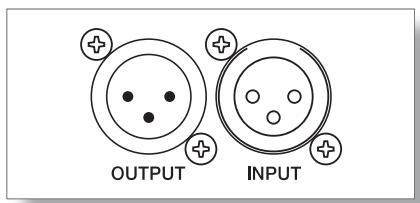
The inputs INPUT A & INPUT B of the CL series are electronically balanced. The voltage gain of all models is set to 32 dB (constant gain). This results however in different input sensitivities for the different models (see table), but the level adjustment of active crossovers or signal processors in multi-way systems is much easier. Power amplifiers with different output power can be changed without consideration, the crossovers have not to be adjusted due to the constant amplification of the whole unit line. If external voltage limiters are used, they should be set to the used power class with consideration of the connected speaker systems. The XLR-type connectors OUTPUT A & OUTPUT B are prepared for „through-connecting“ input signals to additional external power amps. The input signal is directly routed to these output connectors. There are no repeaters or other electronic components within that signal path. Accordingly, input and output connectors of the corresponding channel are interconnected in parallel, offering permanent electrical connection, without regard to the setting of the Power-ON switch.
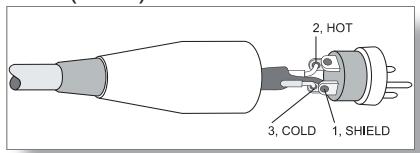
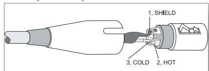
Although having XLR-type output connectors, some mixing console models provide unbalanced output connection only. When using mixers with unbalanced outputs, bridging PIN1 and PIN3 of the power amp's input connectors or leaving PIN3 of the cable's plugs unconnected is necessary. Otherwise, when feeding in unbalanced audio signals via PIN3 (b, -, „cold“) and PIN2 (a, +, „hot“), strange humming and RF-interference may occur, which very likely will damage the power amplifier and/or the connected speaker cabinets.
NF-CONNECTION CORDS
Choosing high-quality balanced cables (two conductors for the audio signal plus separate shielding mesh) with XLR-type connectors are recommended for LF-signal connection. Although connecting unbalanced cables to the power amplifier inputs is possible as well, using balanced cables is always preferable. A great number of today's audio appliances employ balanced outputs. With balanced cabling, the shield connects all metal enclosure parts and therefore efficiently eliminates the introduction of external interference – mostly noise and hum.
XLR-type connector pin-assignment
XLR (male)
XLR (female)
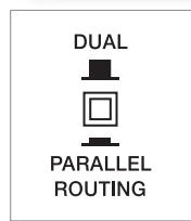
PARALLEL
The input connectors of channel A and channel B are electrically connected in parallel when the selector switch is set to PARALLEL. However, individually controlling the volume of both channels is still possible via the corresponding level controls A and B.
DUAL
If the selector switch is set to DUAL, the audio signals of channels A and B are independently amplified.
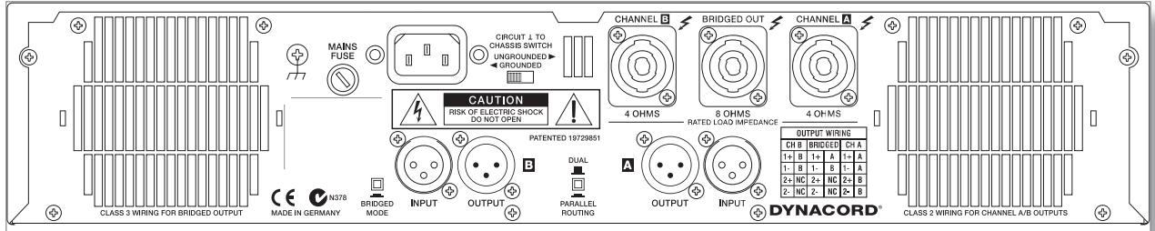
POWER AMP OUTPUT CONNECTORS
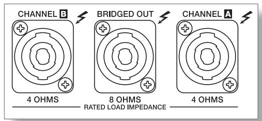
Power amp output connection for the two channels A (left) and B (right) is provided via SPEAKON-type output connectors.
A plastic cover to prevent inadvertent erroneous connection protects the BRIDGED OUT connector. Make sure to remove the cover only when actually operating the power amplifier in Bridged-Mode.
CAUTION!
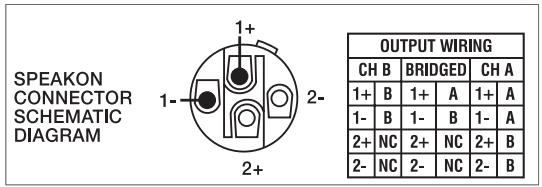
Pins 2 + / 2- of the CHANNEL A SPEAKON output, which normally are not in use, are also connected to output B to ensure comfortable connection of 2-way speaker cabinets (e.g in Bi-Amping Mode) when using 4-wire Speakon cables.
To prevent short-circuit and/or to protect your speaker systems from being damaged when connecting the cabinets, please make sure to mind the Low- and High channels' specific pin-assignments! If, for example, the subwoofer audio signal is used to feed a tweeter, it is more than likely that this will instantly destroy the HF-driver's coil.
WARNING:
The speaker output terminals are marked with a symbol “ ”, which signifies that these terminals are hazardous live and present a risk of electric shock to the user.
BRIDGED MODE

With the BRIDGED-MODE switch being engaged, using the channel A input for audio signal feed is mandatory, since input B provides no function. While the amplifier of channel A operates as usual, the audio signal is internally inverted and routed to the amplifier of channel B. Both amps - A and B - now work in push-pull operation to provide doubled output voltage at the BRIDGED-OUT connector.
The regular output voltage of each amplifier channel A / B is still present at the corresponding output connector CHANNEL A or CHANNEL B. However, using these signals is not recommendable because of the aforementioned phase inversion. Operating the power amp in Bridged Mode with loads of 2ohms connected is not allowable.
CAUTION: Extremely high voltages might be present at the BRIDGED OUT connector during Bridged-Mode operation. The connected loudspeaker systems have to be capable of handling such high voltages. Please make sure that power handling specifications as stated in the documentation supplied with your speaker systems match the specifications of the power amplifier.
GROUND-LIFT SWITCH
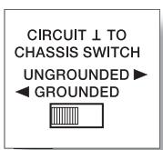
The ground-lift switch allows eliminating noise loops. If the power amplifier is operated together with other equipment in a 19" rack-shelf, setting the switch to its GROUNDED position is recommended. If the power amplifier is operated together with appliances with differing ground potentials, set the switch to its UNGROUNDED position.
MAINS INPUT
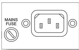
Under normal circumstances, the mains fuse only blows in case of fault. Replacing the fuse is only permissible when using a new fuse of the same type with identical amperage, voltage and blow characteristics. If the mains fuse blows more often, please contact an authorized service centre. The high-performance mains cord supplied with your power amplifier complies to applicable safety regulations, plus that its diameter corresponds to the power
amp's power output capacity. Make sure to use the supplied mains cord for connecting the power amp to the mains. Using mains cords with smaller diameters results in higher leakage and consequently reduced maximum power output capacity.
At 100V and 120V units the mains fuse is installed internally. This is fore safety reasons. In case of a blown mains fuse please contact a qualified service personnel for servicing.
MAINS OPERATION & RESULTING TEMPERATURE
The following tables allow determining power supply and cabling requirements.
The power drawn from the mains network is converted into output power to feed the connected loudspeaker systems and into heat. The difference between power consumption and dispensed power is called power dissipation (Pd). The amount of heat resulting from power dissipation might remain inside of a rack-shelf and needs to be diverted using appropriate measures. The following table is meant as auxiliary means for calculating temperatures inside of a rack-shelf system/cabinet and the ventilation efforts necessary.
The column „Pd“ lists the leakage power in relation to different operational states. The column „BTU/hr“ lists the dispensed heat amount per hour.
| CL800 | Umains [V] | Imains [A] | Pmains [W] | Pout [W] | Pd (6) [W] | BTU/hr(4) |
| idle | 230V | 0,42 | 50 | - | 50 | 170 |
| Max. Output Power @ 8Ω(1) | 230V | 4,4 | 735 | 2 x 240 | 255 | 870 |
| Max. Output Power @ 4Ω(1) | 230V | 7,2 | 1295 | 2 x 400 | 495 | 1690 |
| 1/3 Max. Output Power @ 4Ω(1) | 230V | 4,6 | 770 | 2 x 133 | 504 | 1720 |
| 1/8 Max. Output Power @ 4Ω(1) | 230V | 3,1 | 490 | 2 x 50 | 390 | 1330 |
| 1/8 Max. Output Power @ 4Ω(2) | 230V | 2,7 | 425 | 2 x 50 | 325 | 1110 |
| 1/8 Max. Output Power @ 4Ω(2),(5) | 254V | 3,0 | 600 | 2 x 63 | 474 | 1615 |
| 1/8 Max. Output Power @ 4Ω(3) | 230V | 2,8 | 430 | 2 x 50 | 330 | 1125 |
| 1/8 Max. Output Power @ 4Ω(3),(5) | 254V | 3,1 | 530 | 2 x 63 | 404 | 1380 |
| Normal Mode (-10dB) @ 4Ω(1) | 230V | 2,8 | 440 | 2 x 40 | 360 | 1230 |
| Rated Output Power (0dB) @ 4Ω(1) | 230V | 6,4 | 1130 | 2 x 300 | 530 | 1810 |
| Alert (Alarm) Mode (-3dB) @ 4Ω(1) | 230V | 4,9 | 820 | 2 x150 | 520 | 1775 |
| Max. Output Power @ 2Ω(1) | 230V | 11,2 | 2150 | 2 x 600 | 950 | 3240 |
| 1/8 Max. Output Power @ 2Ω(1) | 230V | 4,8 | 800 | 2 x 75 | 650 | 2220 |
| 1/8 Max. Output Power @ 2Ω(2) | 230V | 4,2 | 680 | 2 x 75 | 530 | 1810 |
| 1/8 Max. Output Power @ 2Ω(3) | 230V | 4,2 | 685 | 2 x 75 | 535 | 1825 |
| CL1200 | Umains [V] | Imains [A] | Pmains [W] | Pout [W] | Pd (6) [W] | BTU/hr(4) |
| idle | 230V | 0,45 | 54 | - | 54 | 185 |
| Max. Output Power @ 8Ω(1) | 230V | 6,3 | 1070 | 2 x 350 | 370 | 1260 |
| Max. Output Power @ 4Ω(1) | 230V | 10,4 | 1920 | 2 x 600 | 720 | 2455 |
| 1/3 Max. Output Power @ 4Ω(1) | 230V | 6,2 | 1065 | 2 x 200 | 665 | 2270 |
| 1/8 Max. Output Power @ 4Ω(1) | 230V | 2,6 | 400 | 2 x 75 | 250 | 855 |
| 1/8 Max. Output Power @ 4Ω(2) | 230V | 2,9 | 455 | 2 x 75 | 305 | 1040 |
| 1/8 Max. Output Power @ 4Ω(2),(5) | 254V | 3,1 | 500 | 2 x 93 | 314 | 1070 |
| 1/8 Max. Output Power @ 4Ω(3) | 230V | 2,9 | 450 | 2 x 75 | 300 | 1025 |
| 1/8 Max. Output Power @ 4Ω(3),(5) | 254V | 3,2 | 550 | 2 x 93 | 364 | 1240 |
| Normal Mode (-10dB) @ 4Ω(1) | 230V | 2,4 | 365 | 2 x 60 | 245 | 835 |
| Rated Output Power (0dB) @ 4Ω(1) | 230V | 9,6 | 1750 | 2 x 500 | 750 | 2560 |
| Alert (Alarm) Mode (-3dB) @ 4Ω(1) | 230V | 7,0 | 1220 | 2 x 250 | 720 | 2455 |
| Max. Output Power @ 2Ω(1) | 230V | 16,1 | 3180 | 2 x 900 | 1380 | 4710 |
| 1/8 Max. Output Power @ 2Ω(1) | 230V | 3,8 | 645 | 2 x 113 | 419 | 1430 |
| 1/8 Max. Output Power @ 2Ω(2) | 230V | 4,1 | 680 | 2 x 113 | 454 | 1550 |
| 1/8 Max. Output Power @ 2Ω(3) | 230V | 4,4 | 720 | 2 x 113 | 494 | 1685 |
(1) Sine Modulation (1kHz)
(2)VDE-Noise
(3) pink-Noise EN60065 / 7. Edition
(4) 1BTU = 1055.06J = 1055.06Ws
(5) 10% Mains Over Voltage
(6) Pd = Leakage Power
The following factors allow direct proportional calculation of the mains current Imain for different mains supply voltages:
100V = 2.3 . 120V = 1.9 . 220V = 1.05 . 240V = 0.96
| CL1600 | Umains [V] | Imains [A] | Pmains [W] | Pout [W] | Pd (6) [W] | BTU/hr(4) |
| idle | 230V | 0,5 | 65 | - | 65 | 220 |
| Max. Output Power @ 8Ω(1) | 230V | 8,0 | 1440 | 2 x 500 | 440 | 1500 |
| Max. Output Power @ 4Ω(1) | 230V | 13,2 | 2520 | 2 x 800 | 920 | 3140 |
| 1/3 Max. Output Power @ 4Ω(1) | 230V | 7,5 | 1360 | 2 x 266 | 828 | 2825 |
| 1/8 Max. Output Power @ 4Ω(1) | 230V | 3,0 | 520 | 2 x 100 | 320 | 1090 |
| 1/8 Max. Output Power @ 4Ω(2) | 230V | 3,3 | 570 | 2 x 100 | 370 | 1260 |
| 1/8 Max. Output Power @ 4Ω(2),(5) | 254V | 3,6 | 660 | 2 x 120 | 420 | 1435 |
| 1/8 Max. Output Power @ 4Ω(3) | 230V | 3,8 | 580 | 2 x 100 | 380 | 1295 |
| 1/8 Max. Output Power @ 4Ω(3),(5) | 254V | 4,1 | 695 | 2 x 120 | 455 | 1550 |
| Normal Mode (-10dB) @ 4Ω(1) | 230V | 2,8 | 470 | 2 x 80 | 310 | 1060 |
| Rated Output Power (0dB) @ 4Ω(1) | 230V | 12,5 | 2360 | 2 x 700 | 960 | 3275 |
| Alert (Alarm) Mode (-3dB) @ 4Ω(1) | 230V | 8,8 | 1610 | 2 x 350 | 910 | 3105 |
| Max. Output Power @ 2Ω(1) | 230V | 20,0 | 4000 | 2 x 1100 | 1800 | 6140 |
| 1/8 Max. Output Power @ 2Ω(1) | 230V | 4,5 | 815 | 2 x 138 | 540 | 1840 |
| 1/8 Max. Output Power @ 2Ω(2) | 230V | 5,0 | 825 | 2 x 138 | 550 | 1875 |
| 1/8 Max. Output Power @ 2Ω(3) | 230V | 5,4 | 905 | 2 x 138 | 630 | 2150 |
| CL2000 | Umains [V] | Imains [A] | Pmains [W] | Pout [W] | Pd (6) [W] | BTU/hr(4) |
| idle | 230V | 0,6 | 72 | - | 72 | 246 |
| Max. Output Power @ 8Ω(1) | 230V | 10,0 | 1712 | 2 x 600 | 512 | 1747 |
| Max. Output Power @ 4Ω(1) | 230V | 16,3 | 2991 | 2 x 1000 | 991 | 3381 |
| 1/3 Max. Output Power @ 4Ω(1) | 230V | 9,7 | 1646 | 2 x 333 | 979 | 3342 |
| 1/8 Max. Output Power @ 4Ω(1) | 230V | 4,0 | 617 | 2 x 125 | 367 | 1252 |
| 1/8 Max. Output Power @ 4Ω(2) | 230V | 4,4 | 696 | 2 x 125 | 446 | 1522 |
| 1/8 Max. Output Power @ 4Ω(2),(5) | 254V | 4,8 | 815 | 2 x 151 | 513 | 1749 |
| 1/8 Max. Output Power @ 4Ω(3) | 230V | 4,5 | 725 | 2 x 125 | 444 | 1515 |
| 1/8 Max. Output Power @ 4Ω(3),(5) | 254V | 4,8 | 838 | 2 x 151 | 536 | 1827 |
| Normal Mode (-10dB) @ 4Ω(1) | 230V | 3,6 | 558 | 2 x 100 | 358 | 1222 |
| Rated Output Power (0dB) @ 4Ω(1) | 230V | 15,1 | 2750 | 2 x 850 | 1050 | 3583 |
| Alert (Alarm) Mode (-3dB) @ 4Ω(1) | 230V | 10,9 | 1905 | 2 x 425 | 1055 | 3600 |
| Max. Output Power @ 2Ω(1) | 230V | 25,4 | 5255 | 2 x 1500 | 2255 | 7694 |
| 1/8 Max. Output Power @ 2Ω(1) | 230V | 6,0 | 1008 | 2 x 188 | 633 | 2160 |
| 1/8 Max. Output Power @ 2Ω(2) | 230V | 6,5 | 1119 | 2 x 188 | 744 | 2539 |
| 1/8 Max. Output Power @ 2Ω(3) | 230V | 6,5 | 1086 | 2 x 188 | 711 | 2426 |
(1) Sine Modulation (1kHz)
(4) 1BTU = 1055.06J = 1055.06Ws
The following factors allow direct proportional calculation of the mains current Imain for different mains supply voltages: 100V = 2.3 . 120V = 1.9 . 220V = 1.05 . 240V = 0.96
WARNING: TO REDUCE THE RISK OF FIRE OR ELECTRIC SHOCK, DO NOT EXPOSE THIS APPLIANCE TO RAIN OR MOISTURE.
AVIS: RISQUÉ DE CHOC ELECTRIQUE. NE PAS OUVRIR.
WARNING: CONNECT ONLY TO MAINS SOCKET WITH PROTECTIVE EARTHING CONNECTION.
WARNING: TO REDUCE THE RISK OF FIRE OR ELECTRIC SHOCK, DO NOT EXPOSE THIS APPLIANCE TO RAIN OR MOISTURE.
AVIS: RISQUÉ DE CHOC ELECTRIQUE. NE PAS OUVRIR.
WARNING: CONNECT ONLY TO MAINS SOCKET WITH PROTECTIVE EARTHING CONNECTION.
MODE BRIDGED (Derivation)

- Amplifier at rated conditions, both channels driven, 8 load, unless otherwise specified.
| CL800 | CL1200 | CL1600 | CL2000 | |||||||||
| Load Impedance | 2 Ω | 4 Ω | 8 Ω | 2 Ω | 4 Ω | 8 Ω | 2 Ω | 4 Ω | 8 Ω | 2 Ω | 4 Ω | 8 Ω |
| Max. Midband Output Power THD = 1%, 1kHz, Dual Channel | 600W | 400W | 240W | 900W | 600W | 350W | 1100W | 800W | 500W | 1500W | 1000W | 600W |
| Rated Output Power THD < 0,1%, 20Hz ... 20kHz | --- | 300W | 150W | --- | 500W | 250W | --- | 700W | 350W | --- | 850W | 450W |
| Max. Single Channel Output Power Dynamic Headroom, IHF-A | 1100W | 580W | 300W | 1450W | 850W | 450W | 2200W | 1200W | 625W | 2700W | 1450W | 750W |
| Max. Single Channel Output Power Continuous, 1kHz | 800W | 480W | 270W | 1200W | 720W | 410W | 1500W | 950W | 550W | 1900W | 1150W | 650W |
| Max. Bridged Output Power THD = 1%, 1kHz | --- | 1200W | 800W | --- | 1800W | 1200W | --- | 2200W | 1600W | --- | 3000W | 2000W |
| Maximum RMS Voltage Swing THD = 1%, 1kHz | 50V | 62V | 72V | 80V | ||||||||
| Power Bandwidth, ref. 1kHz THD =1%, half power @ 4 ohms | 10Hz ... 60kHz | |||||||||||
| Voltage Gain, ref. 1kHz | 32,0 dB | |||||||||||
| Input Sensitivity at rated output power | +1,15 dBu (0,88 V rms) | +3,2 dBu (1,12 V rms) | +4,7 dBu (1,33 V rms) | +5,5 dBu (1,46 V rms) | ||||||||
| THD at rated output power MBW = 80kHz, 1kHz | < 0,05% | |||||||||||
| IMD-SMPTE, 60Hz, 7kHz | < 0,02% | |||||||||||
| DIM 30, 3,15kHz, 15kHz | < 0,01% | |||||||||||
| Maximum Input Level | +22 dBu (9,76 V rms) | |||||||||||
| Crosstalk ref. 1kHz, at rated output power | <-80 dB | |||||||||||
| Frequency Response ref. 1kHz (- 1dB) | 15Hz ... 40kHz | |||||||||||
| Input Impedance active balanced | 20 kΩ | |||||||||||
| Damping Factor, 1kHz | >300 | |||||||||||
| Slew Rate | 25 V/μs | 30 V/μs | 35 V/μs | 35 V/μs | ||||||||
| Signal to Noise Ratio, Amplifier A-weighted | 103,5 dB | 105,5 dB | 107,0 dB | 109,0 dB | ||||||||
| Output Noise, A-weighted | <-70 dB | |||||||||||
| Output Stage Topology | Class AB | Class H | Class H | Class H | ||||||||
| Power Requirements | 100V, 120V, 220V, 230V, 240 V; 50Hz ... 60Hz (factory configured) | |||||||||||
| Power Consumption 1/8 max. output power @ 4 ohms | 600W * | 500W * | 660W * | 725W | ||||||||
| Protections | Audio limiters, High temperature, DC, HF, Back-EMF, Peak current limiters, Inrush current limiters, Turn on delay | |||||||||||
| Cooling | Front-to rear, 3-stage fans | |||||||||||
| Ambient Temperature Limits | +5°C ... +40°C (40°F ... 105°F) | |||||||||||
| Safety Class | I | |||||||||||
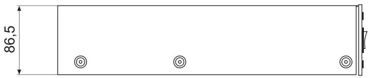
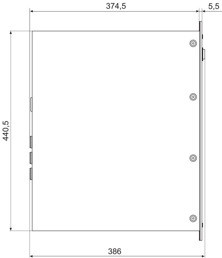
| Dimensions (W x H x D) mm | 483 x 88,1 x 386,8 | |||||||||||
| Weight | 13,5 kg (30,8 lbs) | 15 kg (33 lbs) | 16 kg (35,2 lbs) | 18 kg (39,6 lbs) | ||||||||
| Optional: Rear-rackmount 15,5" Rear-rackmount 18" LPN + Lo-Cut internal filter-card | D112930 (NRS 90262) D112933 (NRS 90264) D112963 (NRS 90268) | |||||||||||
- Measured with 110% of rated mains voltage
Notes:
- Depending on the ambient temperature, the unit might not operate continuously at 2 load in Dual Mode or 4 load in Bridged Mode.
ABMESSAGENGEN / DIMENSIONS (in mm)