
GL36WC4IEB - Air-conditioner FRIGIDAIRE - Free user manual and instructions
Find the device manual for free GL36WC4IEB FRIGIDAIRE in PDF.
| Product Type | Built-in Range Hood |
| Brand | FRIGIDAIRE |
| Model | GL36WC4IEB |
| Dimensions (W x D x H) | Approximately 91.4 x 50.8 x 15.2 cm (36 x 20 x 6 in) |
| Weight | Approximately 11.3 kg (25 lb) |
| Power Supply | 120 VAC, 60 Hz, 10 A (10 A 5x20 mm fuse) |
| Venting | Vertical duct 3¼ x 10 in or round 7 in / horizontal 3½ x 10 in / recirculation possible |
| Fan Speeds | 3 speeds (push buttons) |
| Lighting | 3 levels, PAR20 50W max halogen or R16 40W max incandescent bulbs |
| Heat Sentry Function | High temperature detection, automatic fan activation at maximum speed |
| Included Filters | 2 aluminum mesh filters (dishwasher safe) |
| Recirculation Mode | Requires non-ducted filter kit (sold separately) and a performance ring |
| Maintenance | Metal filters: frequent washing with hot water and mild detergent. Clean surfaces with a damp cloth. Permanently lubricated motor. |
| Safety | Disconnect power before maintenance, mandatory grounding, compliance with building codes |
| Replacement Parts | Available: duct plate, damper, transformer, motor, wheel, filter, bulbs, etc. |
| Warranty | 1 year limited (parts and labor) |
Frequently Asked Questions - GL36WC4IEB FRIGIDAIRE
User questions about GL36WC4IEB FRIGIDAIRE
0 question about this device. Answer the ones you know or ask your own.
Ask a new question about this device
Download the instructions for your Air-conditioner in PDF format for free! Find your manual GL36WC4IEB - FRIGIDAIRE and take your electronic device back in hand. On this page are published all the documents necessary for the use of your device. GL36WC4IEB by FRIGIDAIRE.
USER MANUAL GL36WC4IEB FRIGIDAIRE
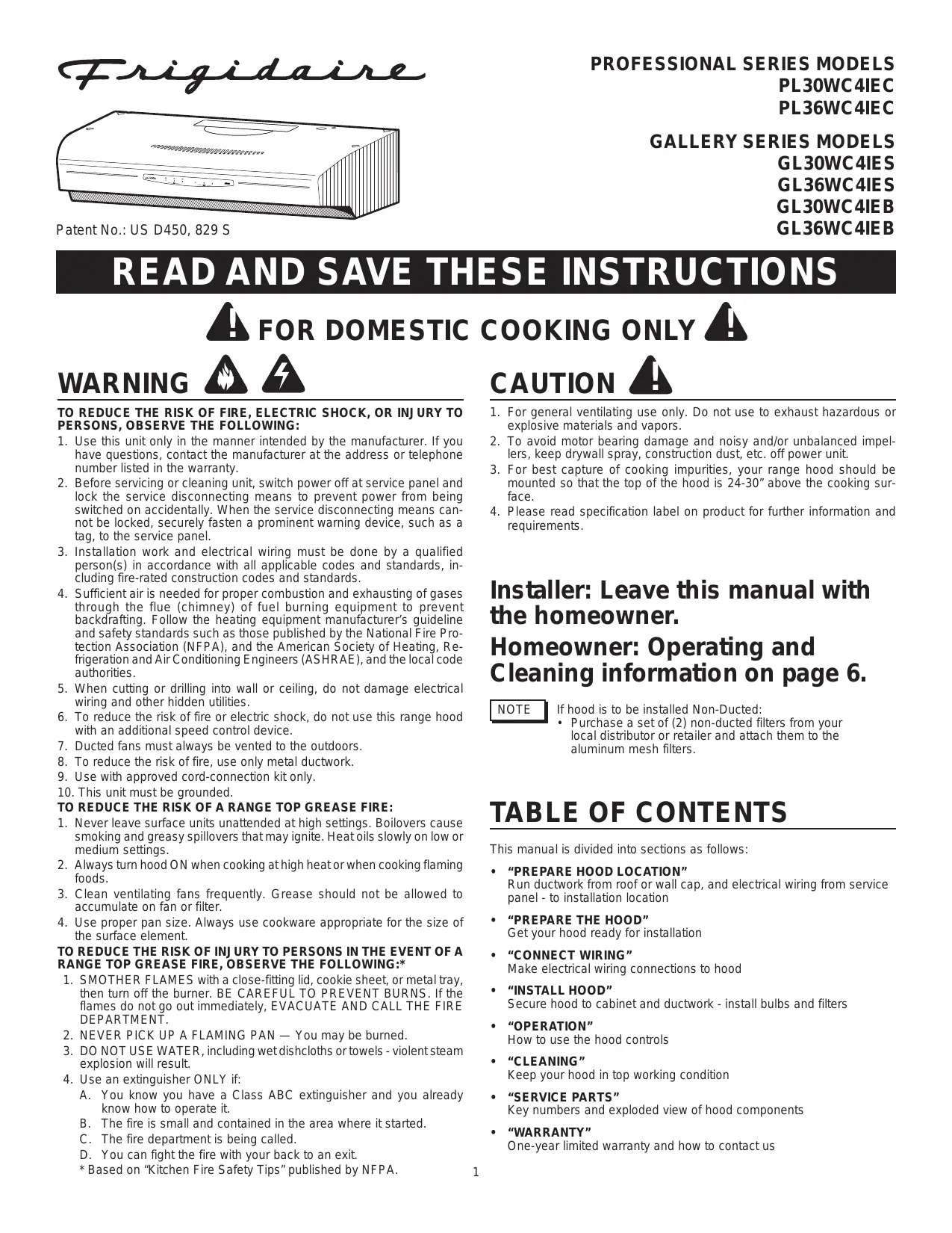
READ AND SAVE THESE INSTRUCTIONS

- Use this unit only in the manner intended by the manufacturer. If you have questions, contact the manufacturer at the address or telephone number listed in the warranty.
- Before servicing or cleaning unit, switch power off at service panel and lock the service disconnecting means to prevent power from being switched on accidentally. When the service disconnecting means cannot be locked, securely fasten a prominent warning device, such as a tag, to the service panel.
- Installation work and electrical wiring must be done by a qualified person(s) in accordance with all applicable codes and standards, including fire-rated construction codes and standards.
- Sufficient air is needed for proper combustion and exhausting of gases through the flue (chimney) of fuel burning equipment to prevent backdrafting. Follow the heating equipment manufacturer's guideline and safety standards such as those published by the National Fire Protection Association (NFPA), and the American Society of Heating, Refrigeration and Air Conditioning Engineers (ASHRAE), and the local code authorities.
- When cutting or drilling into wall or ceiling, do not damage electrical wiring and other hidden utilities.
- To reduce the risk of fire or electric shock, do not use this range hood with an additional speed control device.
- Ducted fans must always be vented to the outdoors.
- To reduce the risk of fire, use only metal ductwork.
- Use with approved cord-connection kit only.
- This unit must be grounded.
TO REDUCE THE RISK OF A RANGE TOP GREASE FIRE:
- Never leave surface units unattended at high settings. Boilovers cause smoking and greasy spillovers that may ignite. Heat oils slowly on low or medium settings.
- Always turn hood ON when cooking at high heat or when cooking flaming foods.
- Clean ventilating fans frequently. Grease should not be allowed to accumulate on fan or filter.
- Use proper pan size. Always use cookware appropriate for the size of the surface element.
TO REDUCE THE RISK OF INJURY TO PERSONS IN THE EVENT OF A RANGE TOP GREASE FIRE, OBSERVE THE FOLLOWING:*
- SMOTHER FLAMES with a close-fitting lid, cookie sheet, or metal tray, then turn off the burner. BE CAREFUL TO PREVENT BURNS. If the flames do not go out immediately, EVACUATE AND CALL THE FIRE DEPARTMENT.
- NEVER PICK UP A FLAMING PAN — You may be burned.
- DO NOT USE WATER, including wet dishcloths or towels - violent steam explosion will result.
- Use an extinguisher ONLY if:
A. You know you have a Class ABC extinguisher and you already know how to operate it.
B. The fire is small and contained in the area where it started.
C. The fire department is being called.
D. You can fight the fire with your back to an exit.
* Based on "Kitchen Fire Safety Tips" published by NFPA.
CAUTION

- For general ventilating use only. Do not use to exhaust hazardous or explosive materials and vapors.
- To avoid motor bearing damage and noisy and/or unbalanced impellers, keep drywall spray, construction dust, etc. off power unit.
- For best capture of cooking impurities, your range hood should be mounted so that the top of the hood is 24-30" above the cooking surface.
- Please read specification label on product for further information and requirements.
Installer: Leave this manual with the homeowner.
Homeowner: Operating and Cleaning information on page 6.
NOTE
If hood is to be installed Non-Ducted:
Purchase a set of (2) non-ducted filters from your local distributor or retailer and attach them to the aluminum mesh filters.
TABLE OF CONTENTS
This manual is divided into sections as follows:
- "PREPARE HOOD LOCATION"
Run ductwork from roof or wall cap, and electrical wiring from service panel - to installation location
- "PREPARE THE HOOD"
Get your hood ready for installation
- CONNECT WIRING
Make electrical wiring connections to hood
- "INSTALL HOOD"
Secure hood to cabinet and ductwork - install bulbs and filters
- “OPERATION”
How to use the hood controls
- "CLEANING"
Keep your hood in top working condition
- "SERVICE PARTS"
Key numbers and exploded view of hood components
WARRANTY
One-year limited warranty and how to contact us
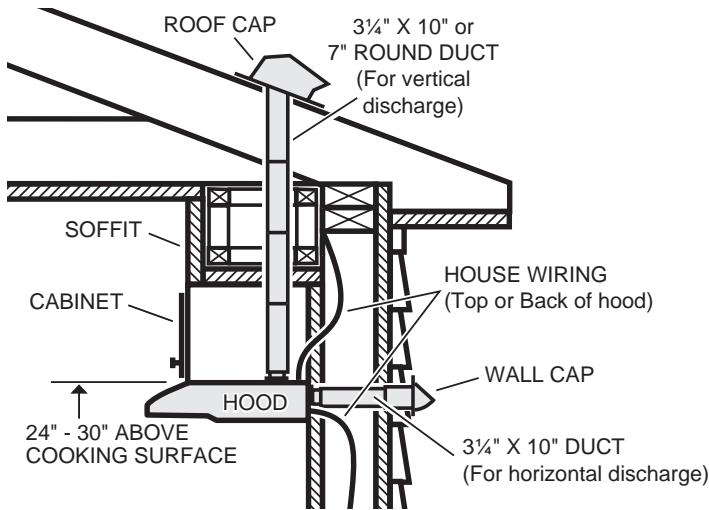


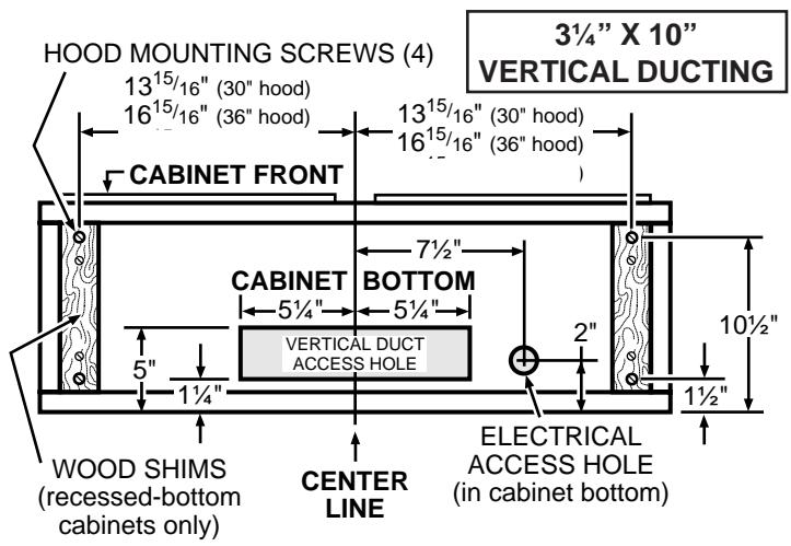
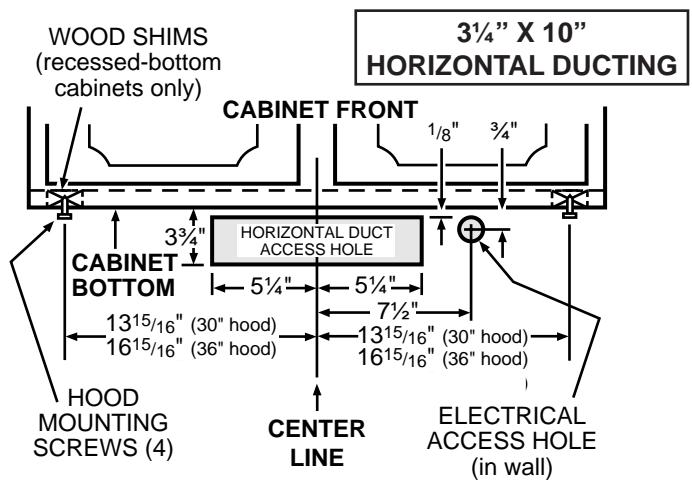
Determine whether hood will discharge vertically (3¼" x 10" or 7" Round), or horizontally (3½" x 10" only). For vertical or horizontal discharge, run ductwork between the hood location and a roof cap or wall cap. For best results, use a minimum number of transitons and elbows.
Use diagrams, below, for proper placement of ductwork and electrical cutout in cabinet or wall. For a non-ducted installation, DO NOT cut a duct access hole.
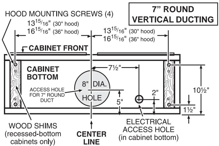

Run house wiring between service panel and hood location.
PREPARE THE HOOD
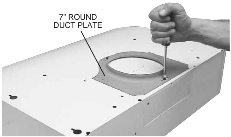

Remove 7" Round Duct Plate from top of hood. Set duct plate aside - with mounting screws.
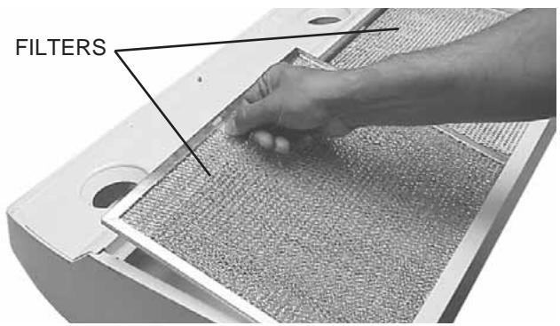

Remove tape holding Filters in place. Pull down on filter tabs or finger holes and lift filters out. Set filters aside.

Remove Teflon-coated bottom cover from hood. Set cover and mounting screws aside.
Teflon® is a registered trademark of DuPont.
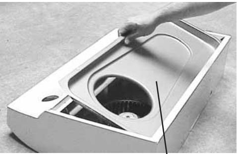
TEFLON®-COATED BOTTOM COVER (Held in place with 2 screws)

Remove Damper/Duct Connector from inside the hood. Set connector aside - with mounting screws and parts bag.
DAMPER/ DUCT CONNECTOR

Remove either top or back wiring knockout and install approved Electrical Cable Clamp.
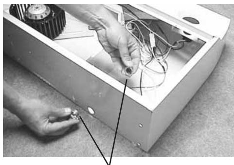
ELECTRICAL CABLE CLAMP
Non-Ducted Installation - Skip to Step 15.
The following Steps (6 thru 14) are for DUCTED INSTALLATION ONLY.
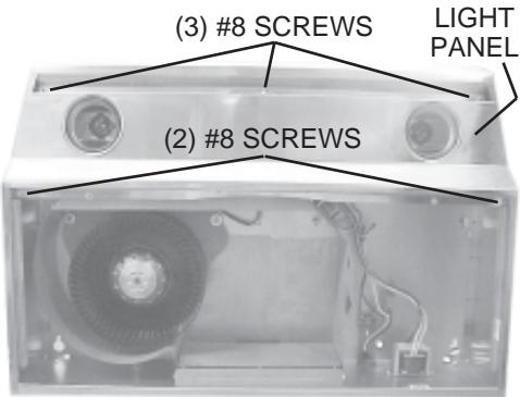

Remove Light Panel - held in place with (3) #8 screws and (2) #8 screws. Disconnect light assembly wire harness (white connector).
PREPARE THE HOOD

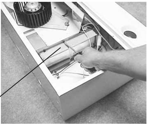
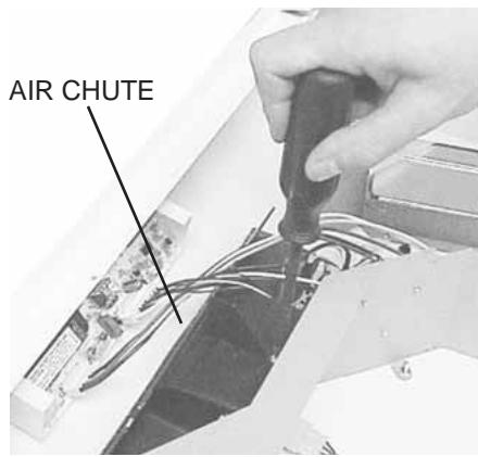
Remove Air Chute - held in place with one (1) screw.
NOTE: Be careful not to disconnect any wires.

Remove Baffle from air chute.
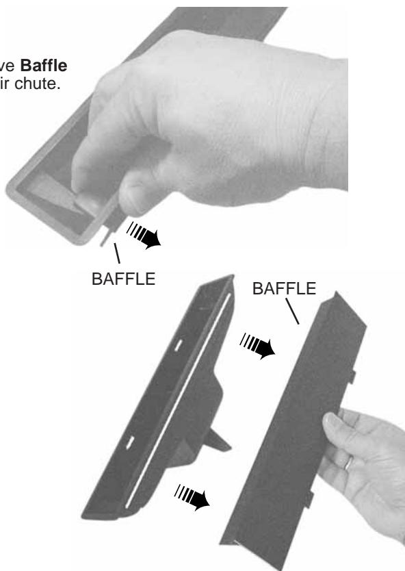

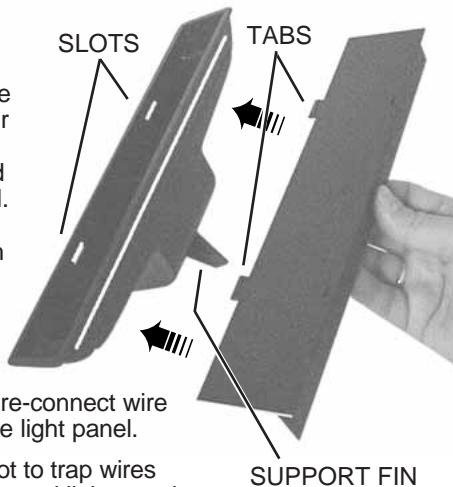
Rotate baffle. Reinsert baffle into air chute (as shown) so that baffle tabs fit all the way into slots in air chute. An audible "click" will be heard when fully installed. This will close off the air flow through the non-ducted slots on top of hood.

Re-install air chute, re-connect wire harness, and replace light panel.
NOTE: Be careful not to trap wires between support fin and light panel.
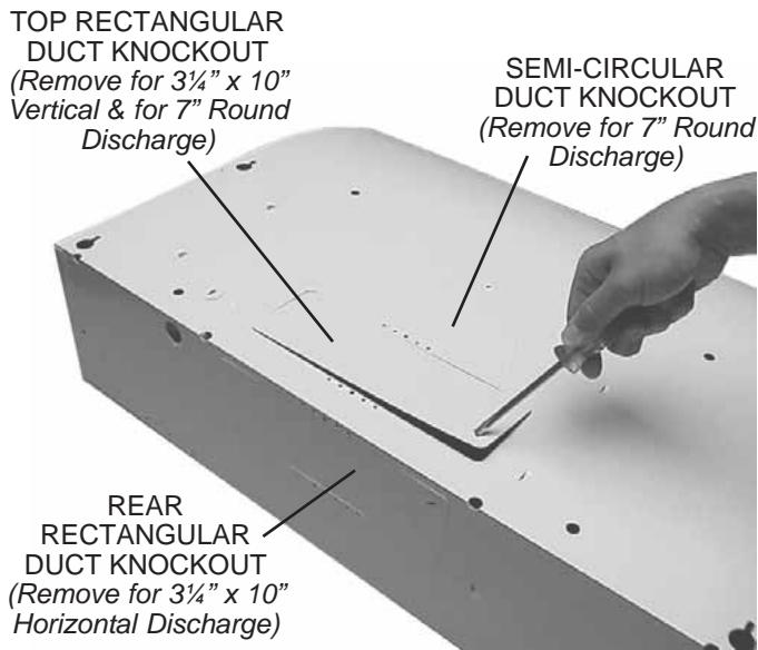
11 Remove appropriate Duct Knockout(s) from top or back of hood.
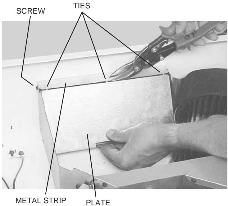
12 Horizontal Discharge Only: Remove the Plate in front of the horizontal discharge knockout. Cut the Ties, lift plate out, and discard plate. DO NOT REMOVE the Metal Strip held in place with two Screws.
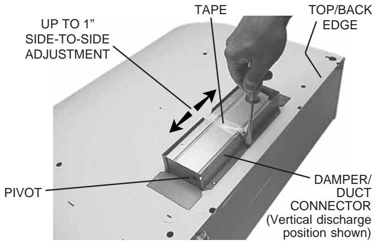
13 3 14 " x 10" Ducted Discharge Only: Remove Tape from damper flap and attach Damper/Duct Connector over knockout opening with screws removed in Step 4 under "PREPARE THE HOOD". Make sure damper Pivot is nearest to Top/Back Edge of hood.
14 7" Round Ducted Discharge Only: Re-install 7" Round Duct Plate removed in Step #1 under "PREPARE THE HOOD". Install a 7" round damper (purchase separately). Damper flap must open freely in direction of airflow (away from range hood).
NOTE To accommodate off-center ductwork, the Damper/Duct Connector can be installed up to 1-inch on either side of hood center or the 7^ Round Duct Plate can be installed up to 1 / 2 on either side of hood center. In extreme off-center installations, one end of the duct connector may need to be trimmed to clear the electrical cable clamp.
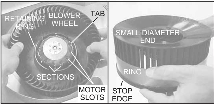
15 Non-Ducted Installations Only: Require a Performance Ring to be attached to the blower wheel.
To install ring:
1. Remove the Blower Wheel by rocking it side to side and applying a slight force to pull wheel from motor. Remove Retaining Ring if necessary.
2. Slide the ring onto the Small Diameter End of the wheel and down to the Stop Edge of the wheel.
3. Reassemble wheel to motor. Make sure Tab on wheel fits into one of the Motor Slots.
4. Push wheel down until it is locked in place.
5. Check that wheel is properly positioned as shown. Press Sections into place if necessary. Make sure wheel turns freely.

WARNING: To reduce the risk of electric shock, make sure power is switched off at the service panel. Lock or tag service panel to prevent power from being switched on accidentally.
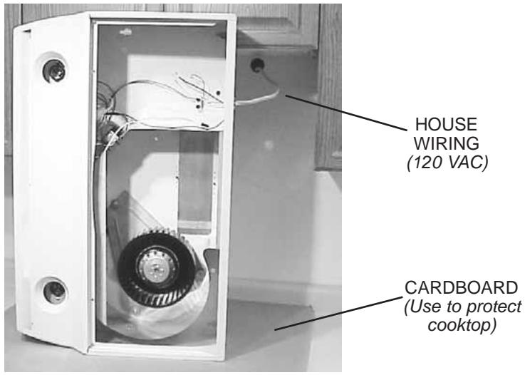

Connect House Wiring (120 VAC) to hood. Use a piece of Cardboard to protect the cooktop, if necessary.
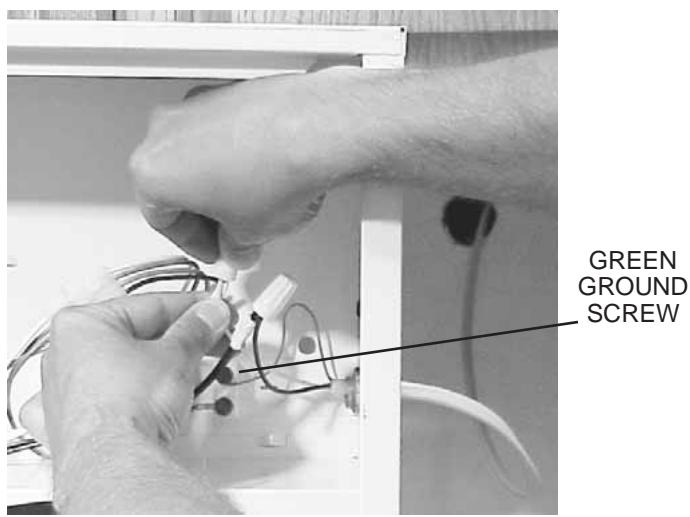

Connect house black to hood black wire, house white to hood white wire, and house ground under Green Ground Screw. Securely tighten cable clamp onto house wiring.
INSTALL HOOD
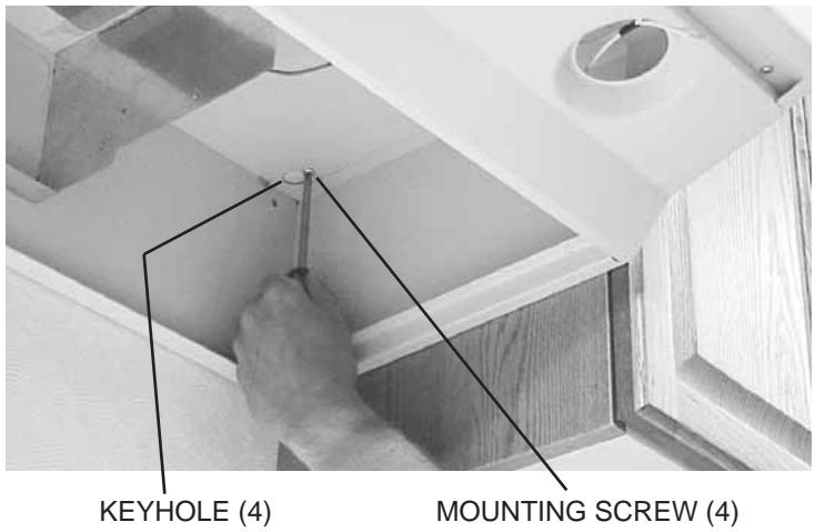

Hang hood from (4) Mounting Screws. Slide hood towards wall until mounting screws are engaged in narrow end of (4) Keyholes. Tighten mounting screws securely. A long screwdriver works best.

Replace bottom cover.
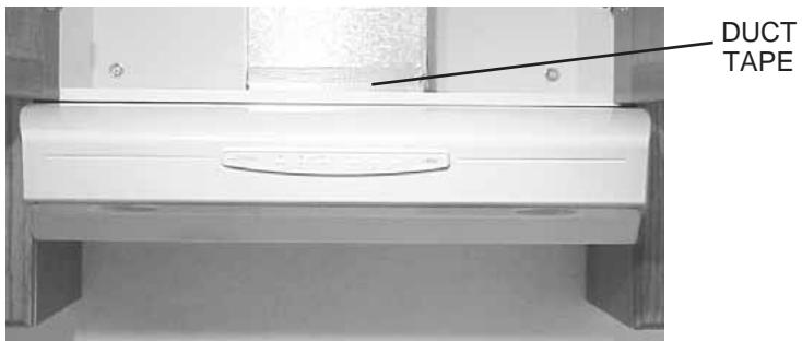

Connect ductwork to hood. Use Duct Tape to make joints secure and air tight.
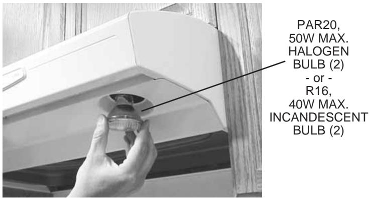

Install (2) PAR20, 50 W Maximum Halogen Bulbs or (2) R16, 40 W Maximum Incandescent Bulbs. Purchase bulbs separately.

CAUTION: Bulbs may be hot! Refer to bulb packaging for further information.

Replace filters, turn on power at service panel, and test for proper operation.
If hood is to be installed Non-Ducted:
Purchase a set of (2) Non-Ducted Filters from your local distributor or retailer and attach them to the aluminum mesh filters.
NOTE: For models that are installed in the non-ducted mode, the most effective operation is achieved at speeds 1 and 2. These speeds provide the most efficient and quiet operation during cooking, while maximizing the benefits of the recirculating filtration system.
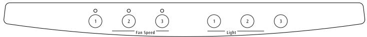
Fan and Lights: 3 push button switches for each. Push any button to select one of 3 fan speeds or one of 3 light levels. Push the same button to turn fan or light off. Press another button to change fan speed or light level. A light above each fan button indicates the fan speed.
Heat Sentry: Your range hood is equipped with the Heat Sentry feature, which monitors temperature. The Heat Sentry will automatically turn the fan on at its highest speed when the temperature is above normal.
1) If a fan setting is selected when the Heat Sentry in on, the light above the fan button will flash on and off.
2) If the fan setting is off when the Heat Sentry is on, the light above fan button 3 will flash on and off rapidly.
After the temperature has lowered to normal, the fan will change to the setting prior to the Heat Sentry turning on.
Fuse: The hood control contains a fuse to protect it from power surges. If the fuse has opened (blown), the green fan-level indicators will operate properly when the fan buttons/switches are pressed - but the fan and lights will not turn on.
The fuse is a 5 × 20 ~mm , 10 Amp, Fast-ACTing, 125V (min.). Common manufacturer and part numbers are: Littlefuse, 217010; Bussmann, GMA10A; Wickmann, 1942100. Radio Shack, Digikey (1-800-344-4539), and most electronic supply stores have them in stock.
To replace the fuse:
- Disconnect power at service entrance.
- Remove filters, bottom panel, light wire harness, and air chute.
- Remove and inspect fuse. If it is not open (blown), additional diagnostics need to be done.
- Install new fuse.
- Re-assemble air chute, light wire harness, bottom panel, and filters.
- Turn on power and check hood/control operation.
CLEANING

WARNING: To reduce the risk of electric shock, disconnect from power supply before cleaning.
Aluminum mesh filters: Clean frequently using hot water and a mild detergent. Filters are dishwasher safe.
Charcoal filters: Clean filter surfaces frequently with a damp cloth and a mild detergent. DO NOT immerse filters in water or put in dishwasher. The special "Clean Sense" feature indicates when the filter is to be replaced. The blue and yellow strips will blend to green when it is time to change the filter. The "Clean Sense" feature works best when facing toward the cooking surface.
To clean hood: Remove filters. Use a damp cloth and a mild detergent to wipe all grease-laden surfaces. Do not use abrasive cloth, steel wool pads, or scouring powder on the Teflon®-coated bottom cover or on any painted surface. Use care when cleaning blower wheel - it must not become bent or misaligned. DO NOT ALLOW WATER TO ENTER MOTOR. Make sure all surfaces are completely dry before re-installing filters and restoring power.
Motor is permanently lubricated. Do not oil or disassemble motor.
Teflon® is a registered trademark of DuPont.
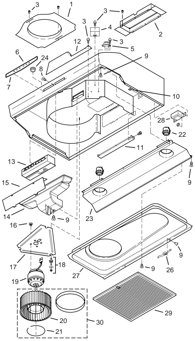
| KEY NO. | DESCRIPTION |
| 1 | 7" Round Duct Plate (includes hardware) |
| 2 | Damper/Duct Connector (includes hardware) |
| 3 | Screw, #8-18 x ¼ Hex* (2 in package) |
| 4 | Motor Capacitor (includes wire nuts & hardware) |
| 5 | Isolation Transformer |
| 6 | Nameplate |
| 7 | Control Panel (includes Key No. 6 & hardware) |
| 8 | Screw for Plastic, #6 x ½ Flat Hd. (3 in package) |
| 9 | Screw, #8-18 x 3/8 (2 in package) |
| 10 | Ground Screw |
| 11 | Scroll Cover, Outlet (includes hardware) |
| 12 | Scroll Cover, Front (includes hardware) |
| 13 | Control Assembly (includes Key Nos. 6, 7 & hardware) |
| 14 | Air Chute Assembly (includes Key No. 15 & hardware) |
| 15 | Baffle |
| 16 | Screw, Metric M4 x 6mm (4 in package) |
| 17 | Motor Plate (Includes Key No. 18) |
| 18 | Motor Plate Mounting Kit (3 of each part) |
| 19 | Motor (includes Key No. 16) |
| 20 | Blower Wheel (Includes Key No. 21) |
| 21 | Retaining Ring |
| 22 | Lamp Socket Assembly |
| 23 | Light Panel |
| 24 | Hole Plug (1 req.) |
| 25 | Pop Rivet, .125D (3 req.) |
| 26 | Filter Spring Kit |
| 27 | Bottom Cover (includes Key Nos. 9, 25, & 26) |
| 28 | Autotransformer (includes hardware) |
| 29 | Aluminum Mesh Filter (2 in package) |
| 30 | Non-Ducted Blower Wheel Assembly (includes Key Nos. 20 & 21) |
| ** | Non-ducted Filter Kit |
| ** | Wire Harness |
| ** | Control Fuse, 10-Amp |
Order replacement parts by KEY NO.
Standard hardware - may be purchased locally.
* Not illustrated - purchase separately.
Major Appliance Warranty Information
Your appliance is covered by a one year limited warranty. For one year from your original date of purchase, Electrolux will pay all costs for repairing or replacing any parts of this appliance that prove to be defective in materials or workmanship when such appliance is installed, used and maintained in accordance with the provided instructions.
Exclusions
This warranty does not cover the following:
- Products with original serial numbers that have been removed, altered or cannot be readily determined.
- Product that has been transferred from its original owner to another party or removed outside the USA or Canada.
- Rust on the interior or exterior of the unit.
- Products purchased "as-is" are not covered by this warranty.
- Food loss due to any refrigerator or freezer failures.
- Products used in a commercial setting.
- Service calls which do not involve malfunction or defects in materials or workmanship, or for appliances not in ordinary household use or used other than in accordance with the provided instructions.
- Service calls to correct the installation of your appliance or to instruct you how to use your appliance.
- Expenses for making the appliance accessible for servicing, such as removal of trim, cupboards, shelves, etc., which are not a part of the appliance when it is shipped from the factory.
- Service calls to repair or replace appliance light bulbs, air filters, water filters, other consumables, or knobs, handles, or other cosmetic parts.
- Surcharges including, but not limited to, any after hour, weekend, or holiday service calls, tolls, ferry trip charges, or mileage expense for service calls to remote areas, including the state of Alaska.
- Damages to the finish of appliance or home incurred during installation, including but not limited to floors, cabinets, walls, etc.
- Damages caused by: services performed by unauthorized service companies; use of parts other than genuine Electrolux parts or parts obtained from persons other than authorized service companies; or external causes such as abuse, misuse, inadequate power supply, accidents, fires, or acts of God.
DISCLAIMER OF IMPLIED WARRANTY; LIMITATION OF REMEDIES
CUSTOMER'S SOLE AND EXCLUSIVE REMEDY UNDER THIS LIMITED WARRANTY SHALL BE PRODUCT REPAIR OR REPLACEMENT AS PROVIDED HEREIN. CLAIMS BASED ON IMPLIED WARRANTY, INCLUDING WARRANTYES OF MERCHANTABILITY OR FITNESS FOR A PARTICULAR PURPOSE, ARE LIMITED TO ONE YEAR OR THE SHORTEST PERIOD ALLOWED BY LAW, BUT NOT LESS THAN ONE YEAR. ELECTROLUX SHALL NOT BE LIABLE FOR CONSEQUENTIAL OR INCIDENTAL DAMAGES SUCH AS PROPERTY DAMAGE AND INCIDENTAL EXPENSES RESULTING FROM ANY BREACH OF THIS WRITTEN LIMITED WARRANTY OR ANY IMPLIED WARRANTY. SOME STATES AND PROVINCES DO NOT ALLOW THE EXCLUSION OR LIMITATION OF INCIDENTAL OR CONSEQUENTIAL DAMAGES, OR LIMITATIONS ON THE DURATION OF IMPLIED WARRANTYES, SO THESE LIMITATIONS OR EXCLUSIONS MAY NOT APPLY TO YOU. THIS WRITTEN WARRANTY GIVES YOU SPECIFIC LEGAL RIGHTS. YOU MAY ALSO HAVE OTHER RIGHTS THAT VARY FROM STATE TO STATE.
If You Need Service
Keep your receipt, delivery slip, or some other appropriate payment record to establish the warranty period should service be required. If service is performed, it is in your best interest to obtain and keep all receipts. Service under this warranty must be obtained by contacting Electrolux at the addresses or phone numbers below.
This warranty only applies in the USA and Canada. In the USA, your appliance is warranted by Electrolux Major Appliances North America, a division of Electrolux Home Products, Inc. In Canada, your appliance is warranted by Electrolux Canada Corp. Electrolux authorizes no person to change or add to any obligations under this warranty. Obligations for service and parts under this warranty must be performed by Electrolux or an authorized service company. Product features or specifications as described or illustrated are subject to change without notice.
USA
1.800.944.9044
Electrolux Major Appliances
North America
P.O.Box 212378
Augusta, GA 30907

Electrolux
Canada
1.800.668.4606
Electrolux Canada Corp.
5855 Terry Fox Way
Mississauga, Ontario, Canada
L5V 3E4