FFHP092CQ2 - Air-conditioner FRIGIDAIRE - Free user manual and instructions
Find the device manual for free FFHP092CQ2 FRIGIDAIRE in PDF.

User questions about FFHP092CQ2 FRIGIDAIRE
0 question about this device. Answer the ones you know or ask your own.
Ask a new question about this device
Download the instructions for your Air-conditioner in PDF format for free! Find your manual FFHP092CQ2 - FRIGIDAIRE and take your electronic device back in hand. On this page are published all the documents necessary for the use of your device. FFHP092CQ2 by FRIGIDAIRE.
USER MANUAL FFHP092CQ2 FRIGIDAIRE
natural_image
Two simple line drawings of a rectangular box and a circular object, both outlined in white (no text or symbols)Refer to Page 2 for table of contents.
Welcome to the world of simple handling and no worries
Thank you for choosing Frigidaire. This manual contains all of the information required to guarantee your safety and the appropriate use of your air conditioner.
Please read all of the instructions before using the air conditioner and keep this manual for future reference.
We know you will enjoy your new air conditioner and thank you for choosing our product.
We hope you will consider us for future purchases.
Environmental advices
The packaging material used is recyclable. We recommend that you separate plastic, paper and cardboard and give them to recycling companies. If you need to dispose of this appliance in the future, do not throw it away with the rest of your domestic garbage.

natural_image
Stylized globe illustration of a panda holding the globe, no text or symbols present
natural_image
Symbol of a trash bin crossed out by two diagonal lines (no text or numbers present)Attention!!
The air conditioner that you have bought may be slightly different from the one illustrated in this manual. Please refer to the information related to the model you have.
This air conditioner is for domestic use only. It is not recommended for heavy commercial or industrial use.
Contents
- Welcome....01
- Environmental advices....01
- Contents....02
- Safety precautions....03
- Installation:
5.1 Choosing the installation site....04
5.2 Parts list....06
5.3 Indoor unit installation....08
5.4 Outdoor unit installation.... 12
5.5 Refrigerant piping connection....14
5.6 Electrical work....16
5.7 Purging the system....20
5.8 Electrical safety....23
5.9 Gas leak check....23
5.10 Initial operation test....24
Safety precautions
This appliance must be installed by a qualified licensed HVAC technician in accordance with all applicable codes. All electrical connections should be performed by a licensed electrician. Manufacturer's warranty will be voided with failure to comply.
Incorrect Handling cound result in Serious Injury or Death!
- Do not attempt to install the split air conditioner by yourself.
- This air conditioner contains no user-serviceable parts. Always call an authorized Electrolux servicer for repairs.
- When moving the air conditioner, always call an authorized Frigidaire servicer for disconnection and re-installation.
- Do not insert fingers or place objects into the discharge area in the front of the indoor unit.
- Do not insert fingers or place objects into the discharge area in the front of the outdoor unit.
- Do not start or stop the air conditioner by turning off the power at the electrical box.
- In the event of a malfunction (sparks, burning smell, etc.) immediately power off unit and call an authorized Frigidaire servicer.
- Do not operate the air conditioner with wet hands.
- Do not drink any water or condensation that is drained from the air conditioner.
-
Provide occasional ventilation during use. Do not direct airflow at fire places or other heat related sources as this could cause flare ups or make units run excessively.
-
Do not climb on or place objects on the outdoor unit.
- Do not hang objects off the indoor unit.
- Do not place objects containing water on the indoor and/or outdoor units.
- Turn off the air conditioner at the power source when it will not be used for an extended period of time.
- Periodically check the condition of the outdoor unit's installation base for any damage.
- Do not apply heavy pressure to the coil fins of the indoor and/or outdoor units.
- Operate the indoor unit with air filters in place.
- Do not block or cover the intake grille, discharge area and outlet ports.
- Ensure that any electrical/electronic equipment is 36" away from the indoor unit and outdoor unit.
- Do not use or store flammable gases near the indoor and/or outdoor units.
Choosing the installation site
Installation Warnings
- Carefully read the installation manual before beginning.
- Follow each step as shown.
- Observe all local, state and national electric codes. This appliance must be installed by a qualified licensed HVAC technician in accordance with all applicable codes. All electrical connections should be performed by a licensed electrician. Failure to comply will result in a void of the manufacturer's warranty.
- Pay attention to all safety notices.
Precautions for Installation
Installation at the following sites may cause problems. If you must inevitably install the unit at one of these sites, please consult your local distributor beforehand:
- Sites with machine oil.
- Sites with a high concentration of salinity, such as coastal areas.
- Sites with sulfuric gas, such as hot water springs.
- Sites with high frequency equipment, such as wireless equipment, welding machines and medical installations.
- Sites with flammable gases or volatile material.
- Sites with special environmental conditions.
- Laundry rooms.
Indoor Unit
- Install unit where air flow will not be obstructed.
- The installation location must support the weight of the indoor unit.
- The site must be easily accessible for maintenance and replacement of the air filter.
- The installation location must allow for the necessary space around the indoor unit, as shown in the figure 1.1.
- There should be at least 3 feet (1 meter) between the unit and radio or television devices. It is ideal that the unit be installed at the center of the wall.
-
The indoor unit must be kept away from fire, smoke and flammable gases.
-
We recommend the indoor unit to be installed as high up as possible on the inside wall (minimum of 7 feet high), always leaving a space of at least 6" between the top of the indoor unit and the ceiling.
- The installation location must allow for the easy removal of the connector pipe and drain hose.
- The unit must be installed at a location protected from direct sunlight.

text_image
More than 6" More than 6" More than 6"Figure 1.1
Outdoor Unit
- The outdoor unit must be installed at a convenient site that is not exposed to strong winds. The site should be dry and well ventilated.
- The site must support the weight of the outdoor unit and allow for vertical installation.
- The site must be kept away from flammable gases.
- The site must provide enough space around the unit, as shown in figure 1.2.
- Children must not be able to access the installation site.

text_image
More than 12" More than 8.5" More than 12" More than 78" More than 2" More than 18.5"Figure 1.2
Part list
| NUMBER | PART NAME | QTY. | QTY.(Multi Split) | ||
| 1 | Wall Mounting Bracket | 1 | - | ||
| 2 | Drain Joint (Heat Pump only) | 1 | 1 | ||
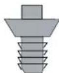
| 3 | Self-tapping screws(For Wall mounting Bracket) | capacity ≤ 18000 Btu's | 5 | - | |
| capacity ≥ 21400 Btu's | 7 | - | |||
| 4 | Remote Control | 1 | - | ||
| 5 | Connecting pipe assembly | Liquid side | 1/4" | 1 | - |
| Gas side | 3/8" (capacity ≤ 12000 Btu's) | ||||
| 1/2" (capacity = 18000 Btu's) | |||||
| 5/8" (capacity ≥ 21400 Btu's) | |||||
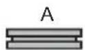
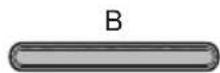
| 6 | Drainage Plug(Heat Pump only) | Type A | 2 | 2 | |
| Type B | 2 | 2 | |||
| 7 | Remote Control Holder | 1 | - | ||
| 8 | Self-tapping screws (For Remote Control Holder) | 2 | - | ||
| 9 | Connecting Adaptor | - | 1 | ||
natural_image
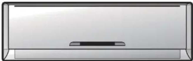
Simple 3D rendering of a rectangular container with a central slot and top edge (no text or symbols)Indoor unit
6
2

natural_image
Technical line drawing of a mechanical component or housing (no text or symbols)1

3
4

8

7

natural_image
Illustration of a portable air conditioner unit with ventilation grilles and control panel (no text or symbols)Outdoor unit
text_image
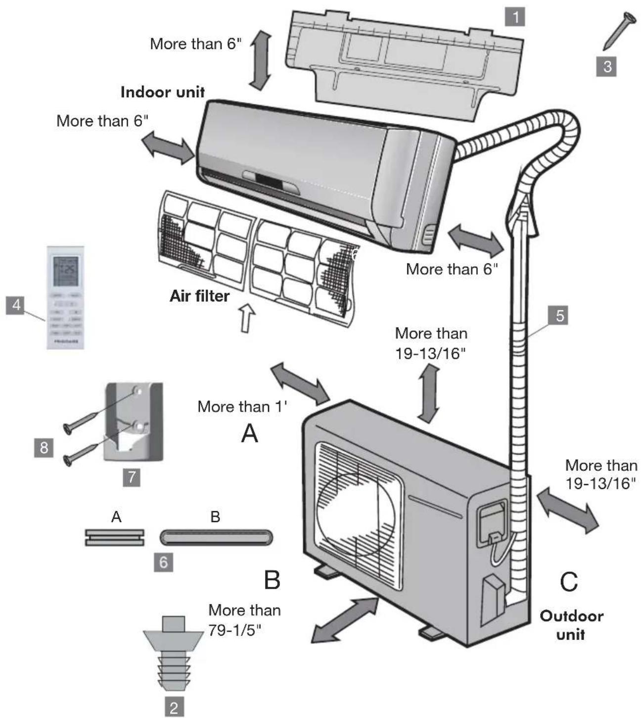
More than 6" Indoor unit More than 6" Air filter More than 6" More than 19-13/16" More than 1' A B C Outdoor unit More than 79-1/5" 4 8 7 6 2 5Attention!!
- This illustration is for explanation purposes only.
- Copper tubes must be insulated independently.
Indoor unit installation
Wall mounting brackets and dimensions

text_image
6" or more from the ceiling Wall mounting bracket Indoor unit outline 6" or more from the wall Refrigerant pipe hole (right) Ø 2.56" 4.21" 3.39" 3.39" A ≤12000 Btu's (A:33.31" B:10.83") 6" or more from the wall Refrigerant pipe hole (right) Ø 2.56"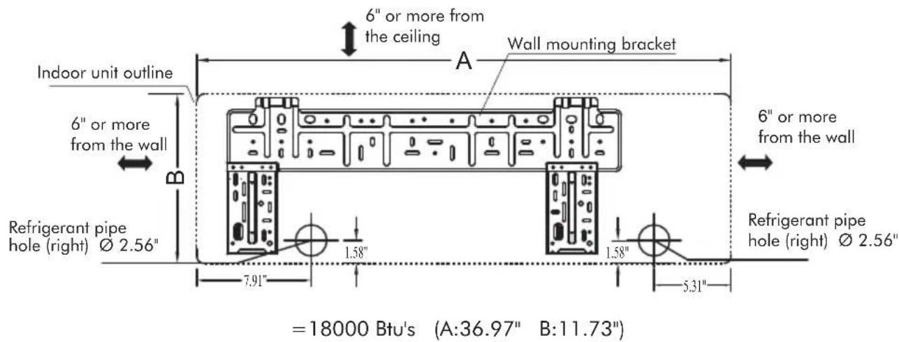
text_image
6" or more from the ceiling Wall mounting bracket Indoor unit outline 6" or more from the wall Refrigerant pipe hole (right) Ø 2.56" 7.91" 1.58" 1.58" 5.31" 6" or more from the wall Refrigerant pipe hole (right) Ø 2.56" =18000 Btu's (A:36.97" B:11.73")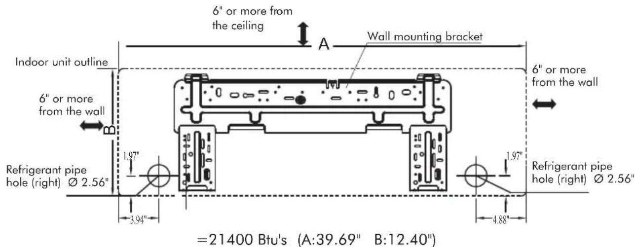
text_image
6" or more from the ceiling A Wall mounting bracket Indoor unit outline 6" or more from the wall Refrigerant pipe hole (right) Ø 2.56" 1.97" 3.94" 4.88" 6" or more from the wall 6" or more from the wall Refrigerant pipe hole (right) Ø 2.56" =21400 Btu's (A:39.69" B:12.40")
text_image
6" or more from the ceiling A Wall mounting bracket Indoor unit outline 6" or more from the wall Refrigerant pipe hole (right) Ø 2.56" 1.97" 3.94"4.86" ≥28000 Btu's (A:53.15" B:12.83") 6" or more from the wall 1.97" Refrigerant pipe hole (right) Ø 2.56"Installing the Wall Mounting Bracket
-
Install the wall mounting bracket horizontally over the structural parts on the wall using the spaces indicated on the bracket, as shown in figure 1.3.
-
In the case of tiled, concrete or similar walls, create 13/64" diameter holes. Place anchor supports for the appropriate assembly screws.
-
Install the wall mounting bracket to
the wall with eight A type screws. 4. At all times securing to the wall studs is recommended.

text_image
Wall mounting bracketFigure 1.3
Attention!!!
Fit the wall mounting bracket and drill holes in the wall according to the wall structure and corresponding mounting points on the wall mounting bracket (Dimensions are in "inches" unless otherwise stated).
Drilling the Hole
-
Determine the position of the hole for the pipes using the wall mounting bracket and drill the pipe hole so that it is tilted slightly downward.
-
Always use a pipe cover with an opening when drilling.
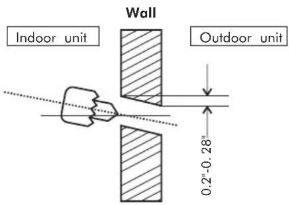
text_image
Wall Indoor unit Outdoor unit 0.2"-0.28"Connective pipe and drainage installation
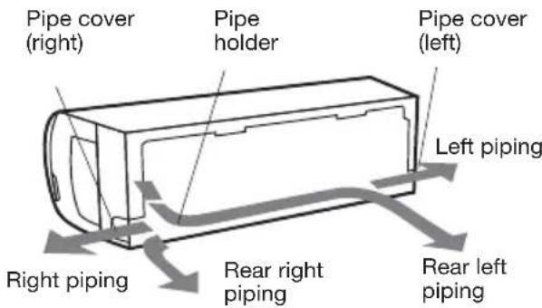
Connective pipe
-
For the left-hand and right-hand piping, remove the pipe cover from the side panel. The pipe cover can be kept as it may be used when relocating the air conditioner to any other place.
-
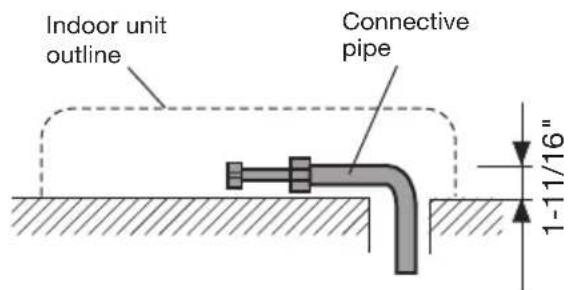
For the rear-right-hand and rear-left-hand piping, install the piping as shown in figure 1.4. Bend the connective pipe to be laid at a height of 1-11/16" or less from the wall. Fix the end of the connective pipe.
Drainage
-
Run the drain hose sloping downward. Do not install the drain hose as illustrated in figure 1.5.
-
When connecting extension drain hose, insulate the connecting part of extension drain hose with a shield pipe, do not let the drain hose slack.
Fastening the Indoor Unit
-
Pass the piping through the hole in the wall.
-
Put the upper claw at the back of the indoor unit on the upper hook of the wall mounting bracket, move the indoor unit from side to side to see that it is securely hooked.
text_image
Pipe cover (right) Pipe holder Pipe cover (left) Left piping Right piping Rear right piping Rear left pipingFigure 1.4
text_image
Indoor unit outline Connective pipe 1-11/16"
text_image
Do not block water flow by a rise.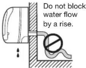
text_image
Do not block water flow by a rise.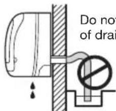
text_image
Do not of drainFigure 1.5

text_image
Upper hook Lower hook- Piping can easily be made by lifting the indoor unit with a cushioning material between the indoor unit and the wall.
- Push the lower part of the indoor unit up on the wall, Then move the indoor unit from side to side, up and down to check if it is hooked securely.
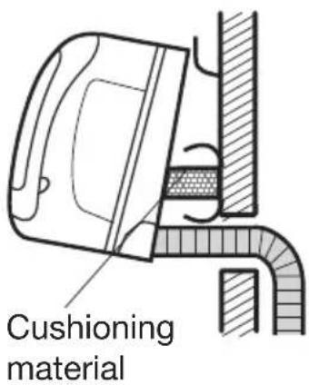
text_image
Cushioning materialPiping and wrapping
- Bundle the tubing, connecting cable, and drain hose with tape securely and evenly as shown in the sideward figure.
- Because the condensed water from rear of the indoor unit is gathered in ponding box and is piped out of room, do not put anything else in the box.
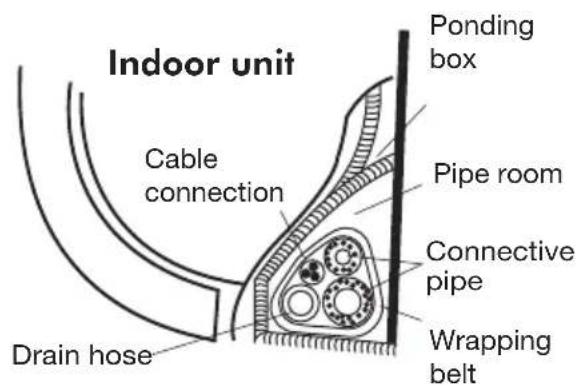
text_image
Indoor unit Cable connection Drain hose Ponding box Pipe room Connective pipe Wrapping beltAttention!!
- Connect the indoor unit first, then the outdoor unit.
- Be careful not to let the drain hose slack.
- Both of the auxiliary piping should be heat insulated.
- Be sure that the drain hose is located at the lowest side of the bundle. Locating at the upper side may cause drain pan to overflow inside the unit.
- Never intercross nor intertwist the power wire with any other wiring.
- Run the drain hose sloped downward to drain out the condensed water smoothly.
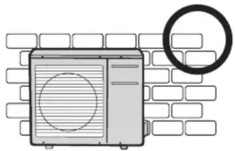
Outdoor unit installation
- Install the outdoor part of the unit on a flat surface to avoid excess noise and vibration. A condenser pad is recommended.
- Direct the air vent toward an area without obstacles.
- Install the unit at the site where it is exposed to as little wind as possible, especially in areas where it is frequently windy.
- If the installation site is exposed to heavy winds, such as in coastal areas, place the unit along the widest part of the wall or use protective plates.
- Be sure there is no obstacle which blocks exhausting air, including schrubs or bushes.
Settlement of outdoor unit. Anchor the outdoor unit tightly and horizontally on a concrete or flat mount with a bolt and nut 2/5" or 5/16" diameter (Purchased separately).
natural_image
Illustration of a wall-mounted air conditioner unit with a circular vent, next to a ring (no text or symbols)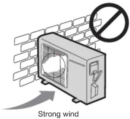
text_image
Strong wind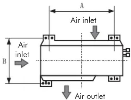
text_image
Air inlet Air outlet| Capacity (BTU/h) | Outdoor unit dimension inch(WxHxD) | A (inch) B (inch) | |
| 33-9/25 x 21-6/25 x 12-3/5 | 21-6/259 | 000-7/25 | |
| 12000 | 33-9/25 x 23-6/25 x 12-3/5 | 22-2/25 | 14-4/25 |
| 18000 | 37-3/5 x 27-3/5 x 15-3/5 | 24-6/25 | 15-9/25 |
| 21400 | 38-3/5 x 31-1/10 x 16-3/5 | 26-4/25 | 17-7/25 |
| 28000 | 38-3/5 x 31-1/10 x 16-3/5 | 26-4/25 | 17-7/25 |
| 33600 | 38-3/5 x 31-1/10 x 16-3/5 | 26-4/25 | 17-7/25 |
| 26000 | 38-3/5 x 31-1/10 x 16-3/5 | 26-4/25 | 17-7/25 |
| 34400 | 42-4/5 x 43-4/5 x 17-3/10 | 31-3/25 | 18-3/25 |
Condensate drainage of outdoor unit (cooling only excluded)
The condensate and defrosting water produced during heating in the outdoor unit can be properly discharged by drainage pipe.
Installation method: Insert the drain connection into one of the holes of the chassis and then connect drainage pipe with drain nozzle. Insert drainage plugs (with different appearance) into the other holes.
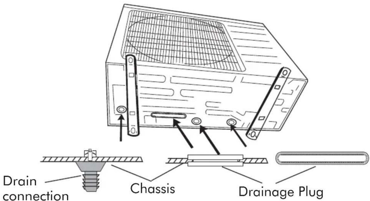
text_image
Drain connection Chassis Drainage PlugRefrigerant piping connection
Unit comes with 25' tubing bundle. It is not recommended to cut. If too long, loop for excess.
Note: Keep original bend so not kinking of the tube occurs.
Flaring work
Main cause for refrigerant leakage is due to defect in the flaring work.
Carry out correct flaring work using the following procedure:
- Cut the pipes and the cable.
A) Use the piping kit accessory or pipes purchased locally.
B) Measure the distance between the indoor and the outdoor unit.
C) Cut the pipes a little longer than the measured distance.
D) Cut the cable 5ft longer than the pipe length.
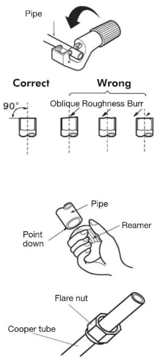
- Burr removal
A) Completely remove all burrs from the cut cross section of pipe/tube.
B) Put the end of the copper tube/pipe in a downward direction as you remove burrs in order to avoid dropping burrs into the tubing.
- Put nut on.
Remove flare nuts attached to indoor and outdoor unit, then put them on pipe/tube having completed burr removal. (It is not possible to put them on after flaring work)
text_image
Pipe Correct 90° Wrong Oblique Roughness Burr Point down Pipe Reamer Flare nut Cooper tube4. Flaring work.
Firmly hold copper pipe in a die in the dimension shown in the table below.
| OUTER DIAMETER (inch) | A (inch) | |
| Max. | Min. | |
| 1/4 | 0.051 | 0.028 |
| 3/8 | 0.063 | 0.039 |
| 1/2 | 0.071 | 0.039 |
| 5/8 | 0.095 | 0.087 |

text_image
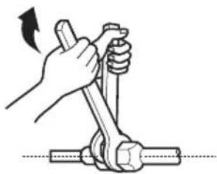
Bar Copper pipe Handle Yoke Red arrow mark Clamp handleConnection Adjustment
- Align the pipes to be connected.
- Screw the flare nut with your fingers, and then tighten it with a spanner and torque wrench, as shown in figure 1.6.
Caution: Excessive twisting may break the nut, depending on the installation conditions.
text_image
Indoor unit tubing Flare nut PipingsFigure 1.6
natural_image
Illustration of a hand using a tool to lift a mechanical component (no text or symbols)| OUTER TIGHTENING DIAMETER (inch) | ADDITIONAL TIGHTENING -in) | TORQUET(DRQUE (lbf |
| 1/4 | 139 174 | |
| 3/8 | 260 304 | |
| 1/2 | 434 477 | |
| 5/8 | 651 694 |
Electrical work
Electric safety regulations for the initial installation
- If there is serious safety problem about the power supply, the technicians should refuse to install the air conditioner and explain to the client until the problem is solved.
- Power voltage should meet the requirements in table 2.1.
-
Over current protection and circuit disconnect should meet the requirements in table 2.1 and the applicable local and national electrical codes.
-
Ensure the air conditioner is grounded well.
- All wiring must comply with local and national electrical codes and be installed by qualified and skilled electricians.
- An individual branch circuit used only for this air conditioner must be available. See table 2.1.
| Electrical Data Table 2.1 | |||||||||||
| Capacity (BTU/h) | System Voltage Volts-Ph.-Freq | Operating Voltage | Outdoor FanCompressor Indoor Fan | MIN. Circuit Ampacity (MCA) | Max. Fuse/Circuit Breaker Amps(MOP) | ||||||
| (Min/Max) | RLA L | RA FLA | Output Watts | Volts FLA | Output Watts | ||||||
| 9000 20 | 8/230-1-60 18 | 7/253 7.17 | / 0.14 | 30 | 208/230V-AC | 0.20 20 | 10 15 | ||||
| 12000 20 | 8/230-1-60 18 | 7/253 6.47 | / 0.14 | 30 | 208/230V-AC | 0.20 20 | 10 15 | ||||
| 18000 20 | 8/230-1-60 18 | 7/253 9.70 | / 0.28 | 60 | 208/230V-AC | 0.32 20 | 13 | 20 | |||
| 21400 20 | 8/230-1-60 | 187/253 | 11.04 / | 1.10 | 90 0.2 | 208/230V-AC | 25 | ||||
| 28000 20 | 8/230-1-60 | 187/253 | 13.50 4 | 0.45 | 120 0.2 | 208/230V-AC | 30 | ||||
| 33600 20 | 8/230-1-60 | 187/253 | 17.50 6 | 0.73 | 170 0.2 | 208/230V-AC | 40 | ||||
| 26000 20 | 8/230-1-60 | 187/253 | 15.82 / | 0.59 | 90 | / | / | / | 21 | 35 | |
| 34400 20 | 8/230-1-60 | 187/253 | 15.60 / | 0.82 | 170 | / | / 21 | / | 35 | ||
Connecting (Power and Control Cable)
- The main power is supplied to the outdoor unit. The field supplied connecting cable from the outdoor unit to indoor unit consists of four wires and provides the power for the indoor unit as well as the communication signal and ground between the outdoor and indoor unit. Two wires are high voltage AC power, one is low voltage DC signal and one is a ground wire.
- Consult local building codes, NEC (National Electrical Code) or CEC (Canadian Electrical Code) for special requirements.
Connect the cable to the indoor unit
- The inside and outside connecting cable can be connected without removing the front grille.
- Connecting cable between indoor unit and outdoor unit shall be approved polychloroprene sheathed flexible type cord.
- Lift the indoor unit panel up, remove the electrical box cover by loosening the screw.
- Ensure the wire color of the outdoor terminal and indoor terminal correspond respectively.
- Wrap the cable not connected to the terminal block with insulation tape so that they will not come in contact with any electrical components. Secure the cable onto the control board with the cord clamp.
Electrical box cover

natural_image
Illustration of a car air conditioner unit with airflow arrow indicating cooling effect (no text or symbols)
text_image
Cable Code wire 0.39" 1.57"Terminal block of indoor unit

text_image
N(1) 2 3To Outdoor Unit
Connect the cable to the outdoor unit
- Remove the electrical control board cover from the outdoor unit by loosening the screw.
- Connect the connective cables to the terminals as identified with their respective matched numbers on the terminal block of indoor and outdoor units. The connective cable to power supply shall be approved polychloroprene sheathed flexible cord.
- Secure the cable onto the control board with the cord clamp.
- To prevent the ingress of water, form a loop of the connective cable as illustrated in the installation diagram of indoor and outdoor units.
- Insulate unused cords (conductors) with PVC-tape. Process them so they could not touch any electrical or metal parts.

text_image
Cover Screw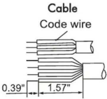
text_image
Cable Code wire 0.39" 1.57"
text_image
N(1) 2 3 L N To indoor unit To power supplySingle split terminal block

text_image
Indoor unit A Indoor unit B Indoor unit C L1 L2 N(1) 2 3 To power supply To indoor unit N(1) 2 3 To indoor unit N(1) 2 3 To indoor unit26000 Btu/h Multi split terminal block
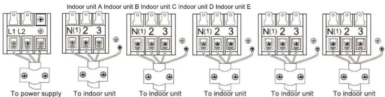
text_image
Indoor unit A Indoor unit B Indoor unit C Indoor unit D Indoor unit E L1 L2 N(1) 2 3 To power supply To indoor unit N(1) 2 3 To indoor unit N(1) 2 3 To indoor unit N(1) 2 3 To indoor unit To indoor unit To indoor unit33400 Btu/h Multi split terminal block
Caution
After the confirmation of the above conditions, prepare the wiring as follows:
- Never fail to have an individual power circuit specifically for the air conditioner. As for the method of wiring, be guided by the circuit diagram posted on the inside of control cover.
- The screws which fasten the wiring in the casing of electrical fittings are liable to come loose from vibrations to which the unit is subjected during the course of transportation. Check them and make sure that they are all tightly fastened. (If they are loose, it could cause burn-out of the wires.)
- Specification of power source.
- Confirm that electrical capacity is sufficient.
- See to that the starting voltage is maintained at more than 90 percent of the rated voltage marked on the name plate.
- Confirm that the cable thickness is as specified in the power source specification.
- Always install an earth leakage circuit breaker in a wet or moist area.
- The following would be caused by voltage drop: vibration of a magnetic switch, which will damage the contact point, fuse breaking, disturbance of the normal function of the overload protector.
- The means for disconnection from a power supply shall be incorporated in the fixed wiring and have an air gap contact separation of at least 1/8" in each active (phase) conductors.
Purging the system
Air and moisture in the refrigeration system have undesirable effects as indicated below:
- Pressure in the system rises.
- Operating current rises.
- Cooling or heating (only for models with heating function) efficiency drops.
- Moisture in the refrigerant circuit may freeze and block capillary tubing.
- Water may lead to corrosion of parts in the refrigeration system.
Therefore, the indoor unit and tubing between the indoor and outdoor unit must apply leakage test and be evacuated to remove any noncondensables and moisture from the system.
Purging the system with a vacuum pump
- Check that each tube (both liquid and gas side tubes) between the indoor and outdoor units have been properly connected and all wiring for the test run has been completed. Remove the service valve caps from both the gas and the liquid side on the outdoor unit. Note that both the liquid and the gas side service valves on the outdoor unit are kept closed at this stage.
- When relocating the unit to another place, perform evacuation using vacuum pump.
- Oil trap should be installed every 16'-25' (no oil trap needed when outdoor unit installed at a lower place than indoor unit).
- Pipe length and refrigerant amount for single split type air conditioner. (see tabel 2.2)
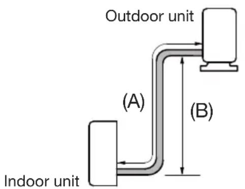
text_image
Outdoor unit (A) (B) Indoor unit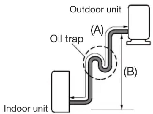
text_image
Outdoor unit (A) Oil trap (B) Indoor unitPiping length under 16' Piping length 16' or more
Table 2.2
| Cooling capacity (BTU/h) | System | Connective pipe length (A) | Max height difference (B) | Air purging | Additional amount of refrigerant to be charged |
| 9000 Heat Pump | 25'~49' 16' | Use vacuum pump. | R410a: 0.22ozs/ft*(Pipe length-25') | ||
| 12000 | Heat Pump | 25'~66' | 33' | Use vacuum pump. | R410a: 0.22ozs/ft*(Pipe length-25') |
| 18000 | Cooling Only | 25'~82' | 33' | Use vacuum pump. | R410a: 0.16ozs/ft*(Pipe length-25') |
| 18000 | Heat Pump | 25'~82' | 33' | Use vacuum pump. | R410a: 0.22ozs/ft*(Pipe length-25') |
| 21400 | Cooling Only | 25'~82' | 33' | Use vacuum pump. | R410a: 0.16ozs/ft*(Pipe length-25') |
| 21400 | Heat Pump | 25'~82' | 33' | Use vacuum pump. | R410a: 0.54ozs/ft*(Pipe length-25') |
| 28000 | Heat Pump | 25'~98' | 66' | Use vacuum pump. | R410a: 0.54ozs/ft*(Pipe length-25') |
| 33600 | Heat Pump Use | vacuum pump.25'~98' 66' | R410a: 0.54ozs/ft*(Pipe length-25') | ||
- Pipe length and refrigerant amount for multi split type air conditioner. (see tabel 2.3)
Table 2.3
| Cooling capacity (BTU/h) | Connective pipe length (Lx) | Max connective pipe total length (H1) | Max height difference (H2) | Air purging | Additional amount of refrigerant to be charged |
| 26000 | 25'~66'(x=1, 2, 3) | 197'(H1=L1+L2+...+Lx, x≤3) | 50' | Use vacuum pump. | R410a: 0.22ozs/ft*(Pipe length-82') |
| 34400 | 25'~82'(x=1, 2, 3, 4, 5) | 246'(H1=L1+L2+...+Lx, x≤5) | 50' | Use vacuum pump. | R410a: 0.22ozs/ft*(Pipe length-131') |

flowchart
graph TD
    A["Outdoor unit"] --> B["Lx"]
    A --> C["ba"]
    A --> D["L4L3L2 L5L1"]
    C --> E["Indoor unit"]
    D --> E
    E --> F["e"]
    style A fill:#f9f,stroke:#333
    style B fill:#ccf,stroke:#333
    style C fill:#cfc,stroke:#333
    style D fill:#cfc,stroke:#333
    style E fill:#fcc,stroke:#333
    style F fill:#fff,stroke:#333
Caution in handling the packed valve integrated in the outlets of outdoor unit.
- Operation of opening packed valve: Open the valve stem until it hits against the stopper. Do not try to open it further.
- Operation of closing packed valve: Securely tighten the valve stem with a special tool. Then securely tighten the valve stem cap with a spanner or the like. Refer to the table on page 17 for valve cap tightening torque.
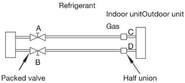
Note: There is a charging port integrated in the low side outlet, but not in the high side outlet. The low side outlet is shown in the sketch map below.
flowchart
graph LR
    Refrigerant["Refrigerant"] --> A["A"]
    Refrigerant --> B["B"]
    Refrigerant --> C["C"]
    Refrigerant --> D["D"]
    Refrigerant --> Gas["Indoor unit"]
    Refrigerant --> HalfUnion["Half union"]
    PackedValve["Packed valve"] --> A
    PackedValve --> B
    Gas --> C
    Gas --> D
    Gas --> HalfUnion
    style Refrigerant fill:#f9f,stroke:#333
    style_Airlock[" "] fill:#ccf,stroke:#333
    style Gas fill:#cfc,stroke:#333
    style Airlock fill:#fcc,stroke:#333
    style Gas fill:#ffc,stroke:#333
    style Airlock fill:#cfc,stroke:#333
    style Gas fill:#cfc,stroke:#333
    style Airlock fill:#fcc,stroke:#333
    style HalfUnion fill:#fcc,stroke:#333

text_image
Flare nut Valve body Charge port Cap Valve stem StopperWhen using the vacuum pump
For method of using a manifold valve, refer to its operation manual.
- Completely tighten the flare nuts at connection point A, B, C and D. Connect valve core removal tool to the charging port, then connect vacuum hose to valve core tool. Open the schrader valve.
Note: The schrader valve is inside the charging port.
-
Connect the other charge hose of manifold valve to the vacuum pump.
-
Fully open the Low Side handle of the manifold valve.
-
Operate the vacuum pump to evacuate. After starting evacuation, slightly loose the flare nut of the Low Side valve on the gas pipe side and check if the air is entering (Operation noise of the vacuum pump changes and a compound meter indicates 0 instead of minus), then tighten the flare nut. The procedure verifies if there are blocks inside the tubes.
-
Make evacuation for 15 minutes or more and check that the compound meter indicates -7-3/5 x 10 Microns Hg (-1x10 Pa). After the evacuation is completed, fully close the Low Side handle of the manifold valve and stop the operation of the vacuum pump.
-
Turn the stem of the packed valve B about 45° counterclockwise for 6\~7 seconds after the gas comes out, then tighten the flare nut again. Make sure the pressure display in the pressure indicator is
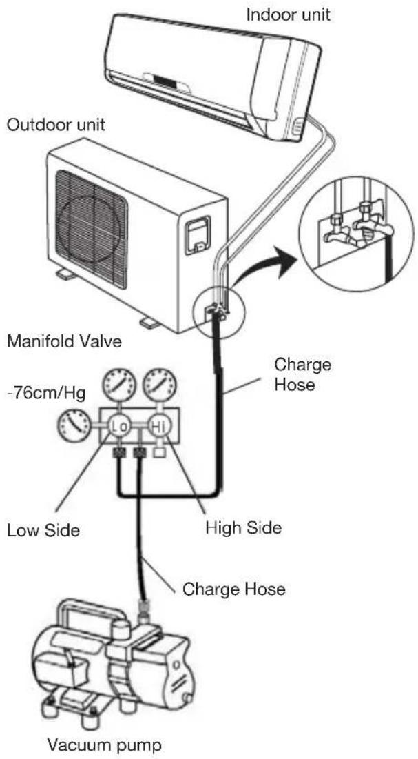
text_image
Indoor unit Outdoor unit Manifold Valve -76cm/Hg Charge Hose Low Side High Side Charge Hose Vacuum pumpa little higher than the atmospheric pressure. This procedure verifies if the refrigerant goes through the tubes correctly.
-
Close the schrader valve, then remove the valve core tool. Replace the charging port cap.
-
Fully open the packed valve stems B and A.
-
Securely tighten the cap of the packed valve.
Electrical safety
Perform the electric safety check after completing installation:
- Insulated resistance: The insulated resistance must be more than 2M.
-
Grounding work: After finishing grounding work, measure the grounding resistance by visual detection and grounding resistance tester. Make sure the grounding resistance is less than 4.
-
Electrical leakage check (performing during test running): During test operation after finishing installation, the serviceman can use the electric probe and multimeter to perform the electrical leakage check. Turn off the unit immediately if electrical leakage happens. Check and find out the solution ways till the unit operates properly.
Gas leak check
Soap water method
Apply a soap water or a liquid neutral detergent on the indoor unit connection or outdoor unit connections by a soft brush to check for leakage of the connecting points of the piping. If bubbles come out, the pipes have leakage point.
Leak detector
Use the leak detector to check for leakage.
Caution
A: Low side valve, B: High side valve valve C and D are ends of indoor unit connection.
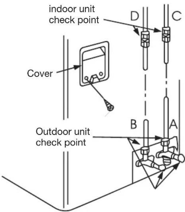
text_image
indoor unit check point Cover Outdoor unit check point D C B AInitial operation test
Perform test operation after completing gas leak check at the flare nut connections and electrical safety check.
- Connect the power, press the ON/OFF button on the remote controller to turn the unit on.
- Use the MODE button to select COOL, HEAT (Only for models with heating function), AUTO and FAN to check if all the functions work well.
- When the ambient temperature is too low(lower than 63 °F), the unit cannot be controlled by the remote controller to run in cooling mode, manual operation can be taken. Manual operation is used only when the remote controller is disable or maintenance necessary.
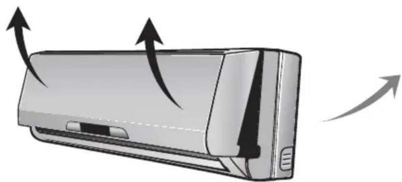
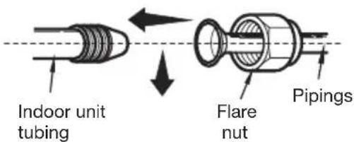
natural_image
Illustration of a wall-mounted air conditioner unit with airflow arrows indicating airflow direction (no text or symbols)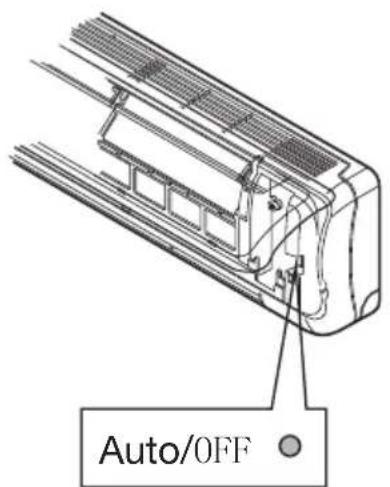
text_image
Auto/OFFManual control button