
100 AMP AUTOMATIC TRANSFER SWITCH - Energy transfer automatic GENERAL ELECTRIC - Free user manual and instructions
Find the device manual for free 100 AMP AUTOMATIC TRANSFER SWITCH GENERAL ELECTRIC in PDF.
| Product Type | Automatic Transfer Switch |
| Brand | GENERAL ELECTRIC (manufactured by Briggs & Stratton Power Products) |
| Model | 071048 (100 A) / 071054 (200 A) |
| Current Capacity | 100 A or 200 A depending on model |
| Rated Voltage | 250 V AC |
| Frequency | 60 Hz |
| Rated Fault Current | 25,000 A symmetrical RMS |
| Operating Temperature Range | -28.8 °C to 40 °C |
| Enclosure Type | NEMA 3R (indoor/outdoor) |
| Main Functions | Automatic transfer between utility/generator, Symphony™ II power management (up to 8 priorities), optional remote modules, LED status display |
| Installation | By qualified electrician only, comply with local codes |
| Maintenance | Visual inspection every 3 months, quarterly test, annual maintenance by a professional |
| Safety | Mandatory grounding, disconnect all power sources before servicing, overload protection |
| Warranty | 3 years for residential use (see terms) |
| Certification | UL Listed |
| Poles | 2 |
Frequently Asked Questions - 100 AMP AUTOMATIC TRANSFER SWITCH GENERAL ELECTRIC
User questions about 100 AMP AUTOMATIC TRANSFER SWITCH GENERAL ELECTRIC
0 question about this device. Answer the ones you know or ask your own.
Ask a new question about this device
Download the instructions for your Energy transfer automatic in PDF format for free! Find your manual 100 AMP AUTOMATIC TRANSFER SWITCH - GENERAL ELECTRIC and take your electronic device back in hand. On this page are published all the documents necessary for the use of your device. 100 AMP AUTOMATIC TRANSFER SWITCH by GENERAL ELECTRIC.
USER MANUAL 100 AMP AUTOMATIC TRANSFER SWITCH GENERAL ELECTRIC
Installation & Operator's Manual
100/200 Amp Automatic Transfer Switch
with Service Disconnect and Symphony™ II Power Management System
Questions?
Help is just a moment away!
Call: Transfer Switch Helpline
800-743-4115 M-F 8-5 CT

Thank you for your purchase of this Briggs & Stratton® Power Products automatic transfer switch. This product is designed for use with specific home standby generators and may not function with generators or remote modules produced by other manufacturers. Seek a qualified electrical professional to determine applicability of this equipment to equipment manufactured by others. When operated and maintained according to the instructions in this manual, your system will provide many years of dependable service.
This manual contains safety information to make you aware of the hazards and risks associated with this system and how to avoid them. We have made every effort to provide for a safe, streamlined and cost-effective installation. As each installation is unique, it is impossible to know of and advise of all conceivable procedures and methods by which installation might be achieved. We do not know all possible hazards and/or the results of each possible method or procedure. It is important that you read and understand these instructions thoroughly before attempting to install or operate this equipment. Save these original instructions for future reference.
This transfer switch and optional remote modules require professional installation before use. Refer to the Installation section of this manual and the installation instructions packaged with the remote modules for instructions on installation procedures. Only licensed electrical contractors should install transfer switches and remote modules. Installations must strictly comply with all applicable federal, state and local codes, standards and regulations. Your installer should follow the instructions completely.
Where to Find Us
You never have to look far to find Briggs & Stratton support and service for your system. Consult your Yellow Pages. There are many authorized service dealers who provide quality service. You can also contact Technical Service by phone at 800-743-4115 between 8:00 AM and 5:00 PM CT, or click on Find a Dealer at BRIGGSandSTRATTON.COM, which provides a list of authorized dealers.
For Future Reference
Please fill out the information below and keep with your receipt to assist in unit identification for future purchase issues.
| Transfer Switch | Remote Module | Remote Module | Remote Module | Remote Module | |
| Model Number | |||||
| Revision | |||||
| Serial Number | |||||
| Date Purchased | |||||
| PRIORITY | N/A |
| Remote Module | Remote Module | Remote Module | Remote Module | Remote Module | Remote Module |
Copyright © 2011. Briggs & Stratton Power Products Group, LLC
Milwaukee, WI, USA. All rights reserved.
Briggs & Stratton Power Products is a registered
trademark of Briggs & Stratton Corporation
Milwaukee, WI, USA
Table of Contents
Important Safety Instructions 4
Installation 5
Home Owner Responsibilities 5
Owner Orientation. 5
Installing Dealer/Contractor Responsibilities 5
Equipment Description 5
Delivery Inspection 6
Mounting Guidelines 6
Power Wiring Interconnections 10
Supervisory Control Terminals 11
System Setup 13
Remote Module Setup 13
Testing the Automatic Transfer Switch 14
Testing the SymphonyTM II Power Management System 14
Controls 16
Operation 16
SymphonyTM II Power Monitor (Optional) 16
Enclosure Door 16
Status LED's 17
Remote Module LED Status Indicators 18
Maintenance. 20
Troubleshooting 21
Transfer Switch Schematic Diagram 22
Transfer Switch Wiring Diagram 23
Warranty 24
Product Specifications. 26
Save These Instructions
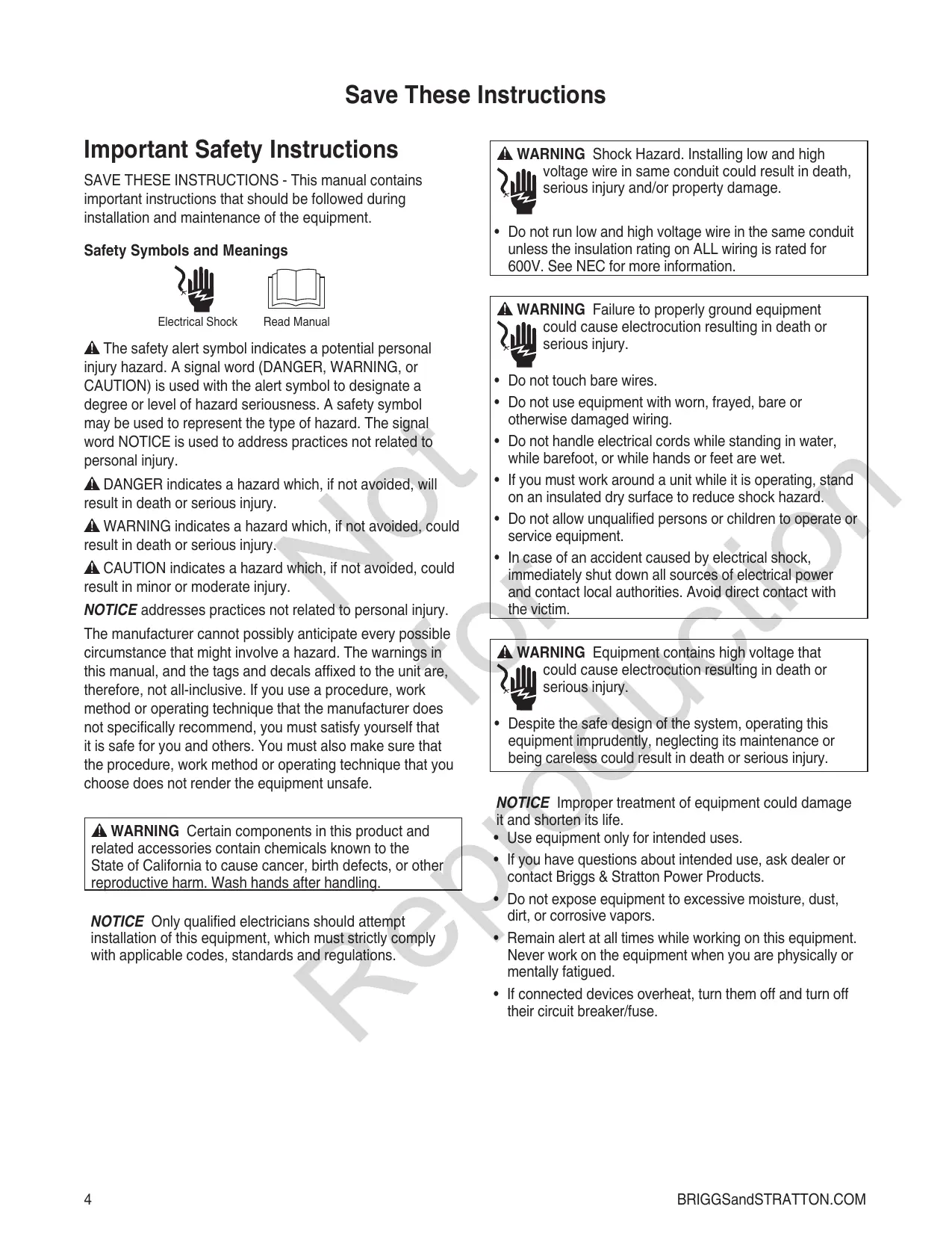
Important Safety Instructions
SAVE THESE INSTRUCTIONS - This manual contains important instructions that should be followed during installation and maintenance of the equipment.
Safety Symbols and Meanings

Electrical Shock

Read Manual
The safety alert symbol indicates a potential personal injury hazard. A signal word (DANGER, WARNING, or CAUTION) is used with the alert symbol to designate a degree or level of hazard seriousness. A safety symbol may be used to represent the type of hazard. The signal word NOTICE is used to address practices not related to personal injury.
DANGER indicates a hazard which, if not avoided, will result in death or serious injury.
WARNING indicates a hazard which, if not avoided, could result in death or serious injury.
CAUTION indicates a hazard which, if not avoided, could result in minor or moderate injury.
NOTICE addresses practices not related to personal injury. The manufacturer cannot possibly anticipate every possible circumstance that might involve a hazard. The warnings in this manual, and the tags and decals affixed to the unit are, therefore, not all-inclusive. If you use a procedure, work method or operating technique that the manufacturer does not specifically recommend, you must satisfy yourself that it is safe for you and others. You must also make sure that the procedure, work method or operating technique that you choose does not render the equipment unsafe.
WARNING Certain components in this product and related accessories contain chemicals known to the State of California to cause cancer, birth defects, or other reproductive harm. Wash hands after handling.
NOTICE Only qualified electricians should attempt installation of this equipment, which must strictly comply with applicable codes, standards and regulations.

WARNING Shock Hazard. Installing low and high voltage wire in same conduit could result in death, serious injury and/or property damage.
- Do not run low and high voltage wire in the same conduit unless the insulation rating on ALL wiring is rated for 600V. See NEC for more information.

WARNING Failure to properly ground equipment could cause electrocution resulting in death or serious injury.
- Do not touch bare wires.
- Do not use equipment with worn, frayed, bare or otherwise damaged wiring.
- Do not handle electrical cords while standing in water, while barefoot, or while hands or feet are wet.
- If you must work around a unit while it is operating, stand on an insulated dry surface to reduce shock hazard.
- Do not allow unqualified persons or children to operate or service equipment.
- In case of an accident caused by electrical shock, immediately shut down all sources of electrical power and contact local authorities. Avoid direct contact with the victim.

WARNING Equipment contains high voltage that could cause electrocution resulting in death or serious injury.
- Despite the safe design of the system, operating this equipment imprudently, neglecting its maintenance or being careless could result in death or serious injury.
NOTICE Improper treatment of equipment could damage it and shorten its life.
- Use equipment only for intended uses.
- If you have questions about intended use, ask dealer or contact Briggs & Stratton Power Products.
- Do not expose equipment to excessive moisture, dust, dirt, or corrosive vapors.
- Remain alert at all times while working on this equipment. Never work on the equipment when you are physically or mentally fatigued.
- If connected devices overheat, turn them off and turn off their circuit breaker/fuse.
Installation
We sincerely appreciate your patronage and have made significant effort to provide for a safe, streamlined and cost-effective installation. Because each installation is unique, it is impossible to know of and advise the trade of all conceivable procedures and methods by which installation might be achieved. Neither could we know of possible hazards and/or the results of each method or procedure.
For these reasons, only current licensed electrical professionals should attempt system installations. Installations must strictly comply with all applicable codes, industry standards and regulations.
Your equipment is supplied with this combined "Installation and Operator's Manual". This is an important document and should be retained by the owner after the installation has been completed.
Every effort has been made to make sure that the information in this manual is both accurate and current. However, the manufacturer reserves the right to change, alter or otherwise improve the system at any time without prior notice.
Home Owner Responsibilities
To help you make informed choices and communicate effectively with your installation contractor(s), read and understand Owner Orientation before contracting or starting your equipment installation.
To arrange for proper installation, contact the store at which you purchased your equipment, your dealer, or your utility power provider.
The equipment warranty is Void unless the system is installed by licensed electrical professionals.
Owner Orientation
The illustrations provided are for typical circumstances and are meant to familiarize you with the installation options available with your system.
Local codes, appearance, and distances are the factors that must be considered when negotiating with an installation professional. As the distance from the existing electrical service increases, compensation in wiring materials must be allowed for. This is necessary to comply with local codes and overcome electrical voltage drops.
These factors will have a direct effect on the overall price of your equipment installation.
Your installer must check local codes AND obtain permits before installing the system.
- Read and follow the instructions given in this manual.
- Follow a regular schedule in caring for and using your equipment, as specified in this manual.
Installing Dealer/Contractor Responsibilities
- Read and observe the Important Safety Instructions.
- Read and follow the instructions given in this manual.
- The installer may need to provide appropriate rated contactors based on loads to be controlled.
- Discuss with owner their load priority preferences to decide on remote module priority settings.
- Check federal, state and local codes and authority having jurisdiction, for questions on installation.
- Ensure generator is not overloaded with selected loads.
If you need more information about the transfer switch, call 800-743-4115, between 8:00 AM and 5:00 PM CT.
Equipment Description
The transfer switch is designed to transfer selected loads found in normal residential installations to standby power in the event of a primary power outage. The load is connected either to utility power (normal) or home standby power (generator). The transfer switch monitors utility and generator voltages and will automatically connect loads to the appropriate source of power.
The Symphony™ II Power Management System is highly flexible and utilizes individual high and low voltage modules that can be mounted anywhere between the home's main distribution panel and the managed appliance. Designed to communicate via your home's existing power wiring, the power demand and priority sequence of up to 8 appliance loads are relayed back to the standby generator, effectively preventing generator overload while expanding power range and performance. The system is scalable and additional relays can be added as a homeowner's power management needs change over time.
Only a licensed electrician should complete a home standby installation. Service conduit and conductors can be wired directly from the watt-hour meter to the transfer switch. A separate service entrance disconnect and associated wiring is not required when installed per applicable federal, state and local codes, standards and regulations.
Major components of the transfer switch are a 2 pole utility disconnect circuit breaker, a 2 pole generator disconnect circuit breaker, a 2 pole double throw transfer switch, transfer switch control circuit board, Symphony II power management system control circuit board, fused utility terminals and interconnecting wiring. All of these components are housed in a NEMA 3R enclosure that is suitable for both indoor and outdoor installations.
The transfer switch is solenoid-operated from utility or generator inputs and contain suitable mechanical and electrical interlock switches to eliminate the possibility of connecting the utility service to the generator output. It has ratings capable of switching full utility power into the residence. In addition, a manual override lever is provided for the transfer function.
The transfer switch control board has active circuits sensing utility and generator voltages. It creates a signal for generator start-up, switch transfer and retransfer when utility is restored. The transfer switch control board provides status LED's to indicate the power source available.
The Symphony™ II power management system control board contains a test button, a status LED and eight priority load LED's. It creates and sends signals to optional remote modules, instructing them when to add (turn power on) or shed (turn power off) the managed load.
The Symphony II system power line carrier technology has been rigorously tested and has proven to be very robust. However, certain types of devices and appliances in the home generate 'noise' on the power line. Such devices may include non-residential fluorescent ballasts, dimmers, speed controls (lighting and fans), bathroom equipment, kitchen equipment, power tools, phone chargers, and power supplies. These types of devices have the greatest impact on power line communication when located close to a remote module.
AM broadcast radio, X10, power line carrier (PLC), uninterrupted power supply (UPS), transient voltage surge suppression (TVSS) systems, and power filter technology may also cause the Symphony II system to not operate as intended. They may cause interference with the Symphony II system during standby power operation.
If it is determined that power line noise is causing a communication issue with the Symphony II system, the following changes may remedy the issue.
- Have commercial (non consumer use) fluorescent ballasts replaced with residential use ballasts.
- Have a EMI/RFI filter installed in series and near the problematic device.
- Have the remote module rewired to the opposite power line (Line 1 or Line 2) from that of the problematic device.
Refer to Troubleshooting section.
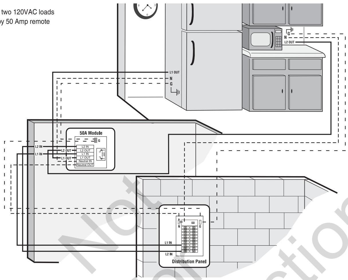
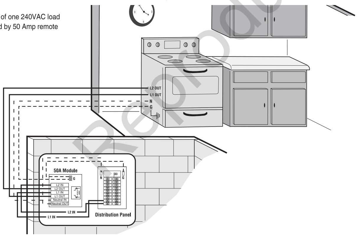
The optional 50 Amp remote module is designed for control by the Symphony II system to add or shed appliance loads connected to it based on a user-defined priority setting. This remote module manages 120VAC or 240VAC, single or double pole loads up to 50 amperes. The remote module's relay state is normally open. Its components are housed in a NEMA 4 enclosure suitable for indoor and outdoor installations.
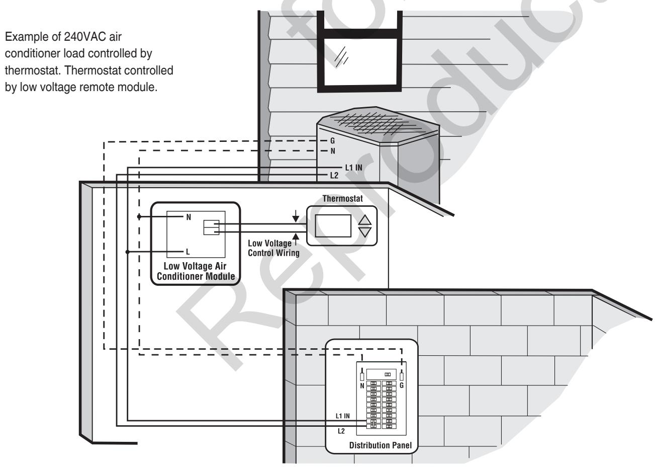
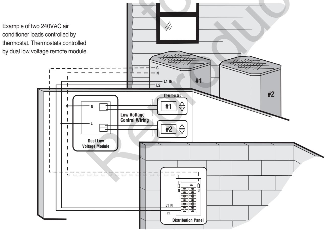
The optional low voltage remote module is designed for control by the Symphony II system to add or shed an air conditioner, heat pump, or low voltage contactor controlled loads based on a user-defined priority setting. The remote module is housed in a NEMA 4 enclosure suitable for indoor and outdoor installations.
Delivery Inspection
After opening the carton, carefully inspect the transfer switch components for any damage that may have occurred during shipment.
If loss or damage is noted at time of delivery, have the person(s) making delivery note all damage on the freight bill and affix his signature under the consignor's memo of loss or damage. If loss or damage is noted after delivery, contact the carrier for claim procedures. Missing or damaged parts are not warranted.
Shipment contents:
Automatic transfer switch
- Installation and operator's manual
- Current transformers (2)
Optional components:
- 50 Amp module
- Low voltage module (single or dual models)
- Symphony™ II power monitor
To be supplied by installer:
- Connecting wire and conduit
- Various specialty tools/equipment
Mounting Guidelines
The transfer switch system circuitry is enclosed in a NEMA Type 3R enclosure suitable for indoor/outdoor use. Guidelines for mounting the enclosure include:
- Install enclosure on a firm, sturdy supporting structure.
- The transfer switch enclosure must be installed with minimum NEMA 3R hardware for conduit connections.
- To prevent switch contact distortion, level and plumb the enclosure. This can be done by placing washers between the enclosure and the mounting surface.
- NEVER install the switch or remote modules where any corrosive substance might drip onto the enclosure.
- Protect the switch at all times against excessive moisture, dust, dirt, lint, construction grit and corrosive vapors.
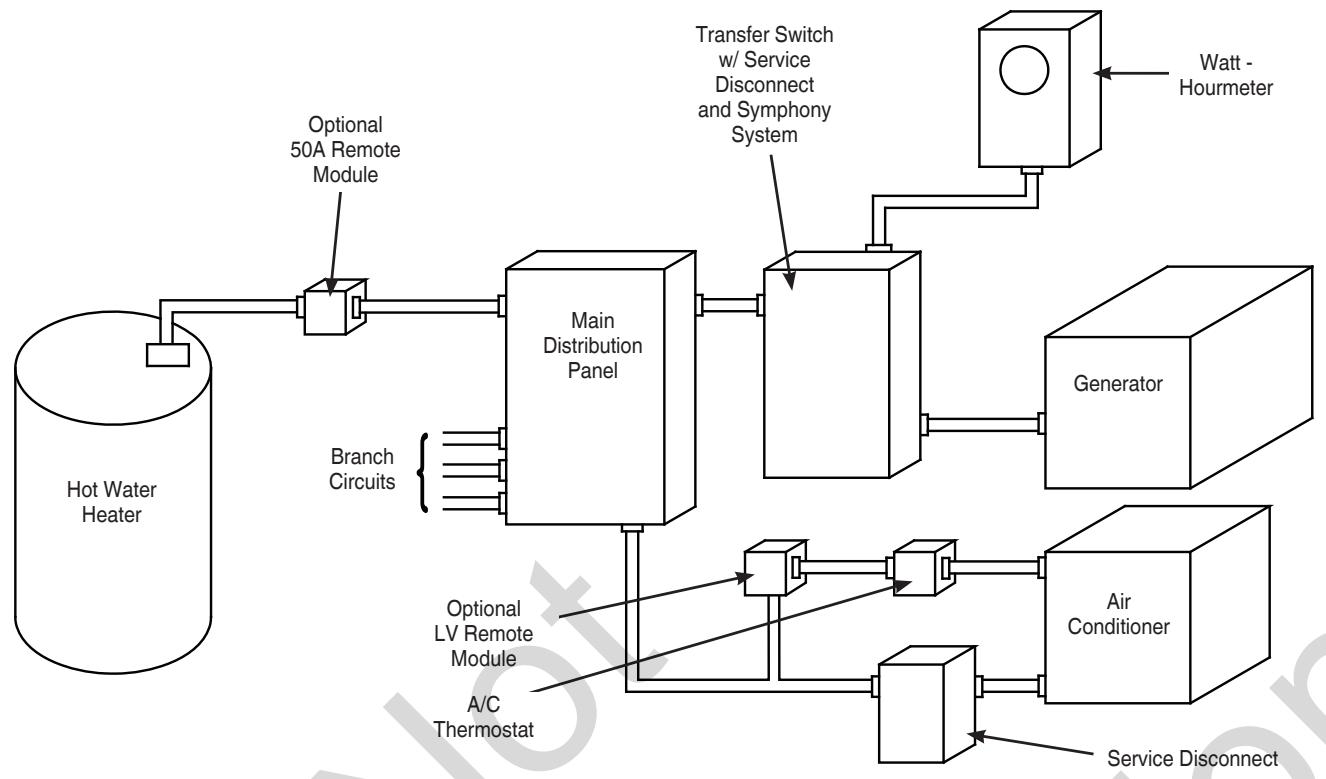
A typical automatic transfer switch installation is depicted on the next page. Examples of remote module installations are also shown. It is best if the transfer switch is mounted near the utility meter, either inside or outside. The remote module can be located anywhere between the main distribution panel and its connected load, either inside or outside. The remote module must be accessible for service. Discuss layout suggestions/ changes with the owner before beginning the system installation process.
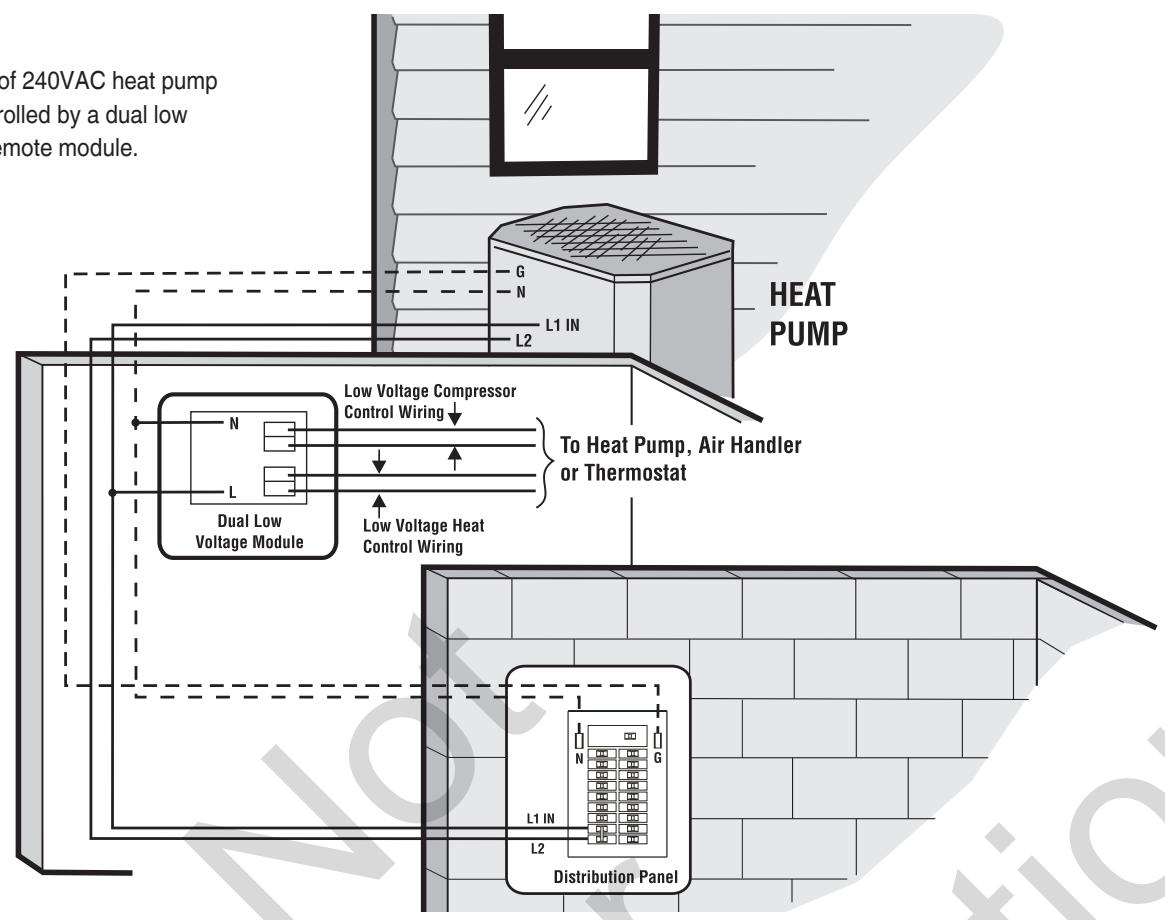
Example of 240VAC heat pump load controlled by a dual low voltage remote module.
Example of two 120VAC loads controlled by 50 Amp remote module.
Example of one 240VAC load controlled by 50 Amp remote module.
Power Wiring Interconnections
NOTICE Improper installation could cause damage to the circuit boards and shorten their life. Installing circuit boards in live circuits will damage the board and is not covered by warranty. ALWAYS disconnect ALL sources of power prior to servicing.
- Remove all power prior to installing this equipment. Failure to do so could cause internal damage to the board when making electrical connections.
- Turn generator to OFF position.
- Turn off utility power to the standby generator and transfer switch.
All wiring must be the proper gauge, properly supported and protected by conduit. All wiring should be done per applicable federal, state and local codes, standards and regulations. Obey wire type and torque specifications printed on the terminal blocks, neutral/ground connectors, and installation instructions.

RNING Shock Hazard. Installing low and high voltage wire in same conduit could result in death, serious injury and/or property damage.
- Do not run low and high voltage wire in the same conduit unless the insulation rating on ALL wiring is rated for 600V. See NEC for more information.
Use installer supplied 300VAC or greater copper wire of a gauge that complies with the latest version of the National Electric Code to complete the following connections between utility power, transfer switch, generator, main distribution panel, and optional remote modules. Apply the necessary correction factors and wire size calculations.
- Set generator's circuit breaker to OFF (open) position.
- Set generator's system switch to OFF position.
- Remove 15 Amp fuse from generator control panel.
- Turn off utility power to the standby generator and transfer switch.
- Connect utility service to transfer switch's utility service disconnect circuit breaker terminals marked "UTILITY CONNECTION".
- Connect utility service neutral to transfer switch neutral terminal.
- Connect main distribution panel feeder conductors to transfer switch terminals marked "LOAD CONNECTION".
-
NOTICE Connect main distribution panel neutral to transfer switch neutral terminal.
-
Connect main distribution panel ground to transfer switch "GND" terminal.
Assure grounding electrode conductor is connected and bonded per applicable federal, state and local codes, standards and regulations.
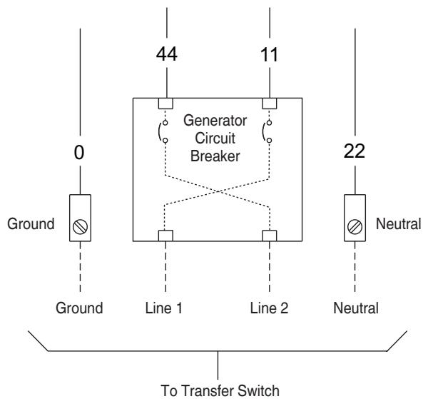
- Connect feeder conductors from transfer switch breaker "GENERATOR CONNECTION" terminals to generator circuit breaker LINE1 and LINE2 terminals. Each conductor must pass through hole of current transformer before making connection.
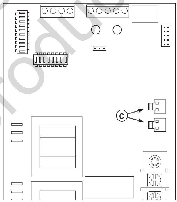
- Plug current transformer leads into "CT1" and "CT2" terminals (C) on transfer switch control board.
- Connect conductor from transfer switch neutral terminal to generator NEUTRAL terminal. Observe generator control panel labeling for terminal identification.
- Connect conductor from transfer switch "GND" terminal to generator control panel "GROUND" terminal. Assure generator equipment grounding conductor is connected per applicable federal, state and local codes, standards and regulations.
- Using minimum #14 AWG conductors, connect the transfer switch "UTILITY 240 VAC" terminals to generator's "240 VAC" terminals via two-pole connector supplied with generator.
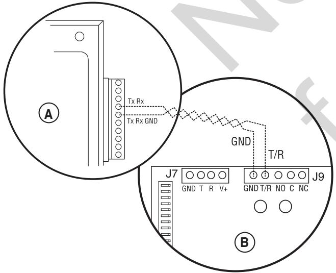
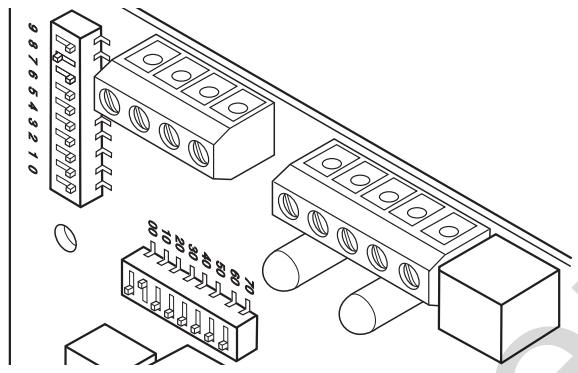
NOTICE TxRx and TxRx GND communication wiring must be connected for the Symphony II System to operate properly.
- Using #18 AWG twisted pair copper conductors, no greater than 200 ft. in length, 300 volt 75^ - 90^ , connect "T/R" and "GND" terminals on transfer switch control board (B) to the generator's control panel (A) "TxRx" and "TxRx GND" terminals via ten pin connector supplied with generator. Count down to the proper pin location on the generator control board since visual alignment with its decal can be misleading:
- Install optional remote modules using the installation instructions provided with each module. Set each module to the agreed-upon priority setting.
- Tighten all wire connections/fasteners to proper torque. See label inside transfer switch enclosure or values listed in remote module installation instructions for proper torque values.
Supervisory Control Terminals
To avoid undesirable operation, we recommend loads be managed only with low voltage or 50 Amp remote modules. Do not use the transfer switch control board supervisory control terminals (if present).
The illustration on the following page shows a completed transfer switch installation. Your actual layout will vary. Illustration callouts are:
A - From utility watt-hour meter
B - Current transformers
C - Transfer switch
D - SymphonyTM II system control board
E - T/R and GND to Generator
F - Transfer switch control board
G - Neutral terminal
H - Neutral bus
J - Ground bus
K - Main distribution panel
L - UTILITY 240VAC to Generator
M - Two pin connector
N - Ten pin connector
P - Generator circuit breaker
R - Generator
S - Generator Neutral terminal
T - Generator Ground terminal
U - Transfer switch ground terminal
V - Load connection to distribution panel
W - Generator disconnect circuit breaker
X - Utility disconnect circuit breaker
Y - Utility connection
Z - Generator connection
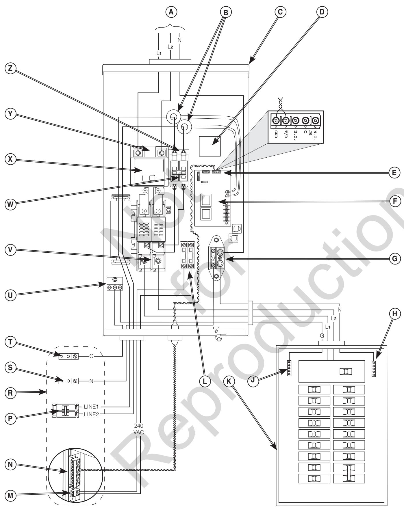
Typical Transfer Switch shown
System Setup
You must perform the following before operating the system:
- If generator is installed in an area regularly subjected to temperatures below 40^ ( 4^ ), select a 50 second warm up time by moving jumper JP2 (C) installed on transfer switch control board from '20' position to '50' position.
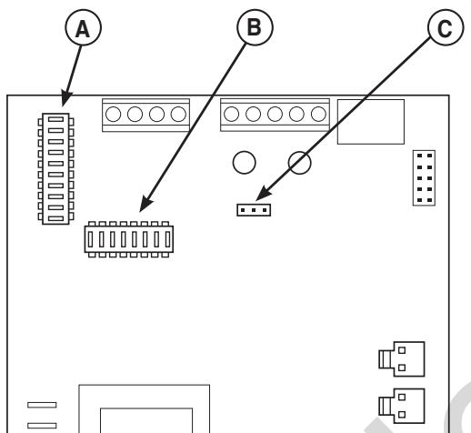
- Set the DPSW1 (A) and DPSW2 (B) dipswitches on the transfer switch control board to match the kW rating of the home standby generator, as described in Setting Dipswitches.
Setting Dipswitches
Dipswitches are used to adjust control board operation based on generator capacity. DPSW1 and DPSW2 switches are set to correspond to total system kW rating. Dipswitch DPSW1 (A) has units of 1,000 watts; Dipswitch DPSW2 (B) has units of 10,000 watts.
NOTICE Use extreme caution when setting dipswitches or damage to control board will result.
- Use a pencil or small piece of plastic to set the dipswitch.
- NEVER use a screwdriver or any type of metal object to set dipswitches.
The "On" position for the dipswitches is the switch number ON. THE TRANSFER SWITCH CONTROL BOARD, not on the switch. For example, for an 18,000 watt generator, set DPSW2 dipswitch 10 to "On" position. Set DPSW1 dipswitch 8 to "On" position. 10,000 plus 8000 equals 18,000 watts. Set only one switch to "On" position on DPSW1 and DPSW2.
NOTICE Air density is less at high altitudes, resulting in less available engine power. Specifically, engine power will decrease 3.5% for each 1,000 feet (300 meters) above sea level and 1% for each 10^ (5.6^) above 77^ (25^) . Generators located in these conditions must have the transfer switch programmed appropriately for this power decrease.
Remote Module Setup
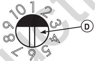
Each remote module features a priority selector (D) that permits control of load-add or load-shed sequence. Priority number is identified on clear protective barrier. Diagrams of each module are shown in Status LED's, later in this manual. Priority 1 is the highest priority - devices set to this priority will be the first load(s) added or last load(s) shed in a load management situation. Priority 8 is the lowest priority.
Priority 9 and 10 are lockouts. Remote module(s) set to these priorities will remain unpowered during any utility power outage. An unlimited amount of remote modules can be assigned to priority 9 or 10.
In consultation with the homeowner, set each remote module's priority selector switch to the desired priority position. Assign a different priority to each remote module for optimum operation.
Testing the Automatic Transfer Switch
WARNING Testing must only be performed by qualified personnel. Equipment contains high voltage that can cause personal injury or death.
- Despite the safe design of the system, operating this equipment imprudently, neglecting its maintenance or being careless can cause possible injury or death.
Turn the utility service disconnect circuit breaker feeding the transfer switch contactor to the "OFF" position. The system's automatic sequence described below will initiate. To return to utility power, turn the utility service disconnect circuit breaker to the "ON" position.
Utility Fail
The generator senses when utility voltage is below 70 percent of nominal. Engine start sequence is initiated after 6 second time delay.
Engine Warm-Up
Time delay to allow for engine warm-up before transfer. Use jumper on transfer switch control board to select delay of 20 seconds or 50 seconds.
Transfer
Transfer from utility to generator supply occurs after voltage is above set levels. The transfer switch control board LED lights will change from green (utility) to red (generator) and the Symphony II status light will change blink status from Blink Blink_Pause_Blink Blink to Blink_Pause_Blink. Minimum engine run time is 5 minutes after transfer.
Load Management
Five minutes after transfer to generator power, the remote modules energize connected load(s) if generator power is available, starting with the highest priority (1) through the lowest priority (8). There is a 10 second delay between each sequential activation.
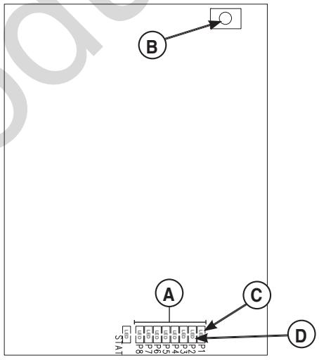
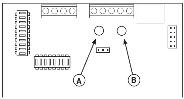
The P1 through P8 LED's (A) on the Symphony II control board will illuminate to show loads being added.
Loads connected to remote modules set to priorities 9 and 10 remain off for the duration of a utility power outage.
Utility Pickup
Voltage pickup level is 80 percent of nominal voltage.
Retransfer
Retransfer from generator to utility power is approximately 10 seconds after utility voltage supply is above pickup level and minimum run time is completed. All remote module(s) will remain OFF for five minutes after the power transfer.
Engine Cool Down
Engine will run for 60 seconds after retransfer.
Testing the Symphony™ II Power Management System
WARNING Testing must only be performed by qualified personnel. Equipment contains high voltage that can cause personal injury or death.
- Despite the safe design of the system, operating this equipment imprudently, neglecting its maintenance or being careless can cause possible injury or death.
The Symphony II system can be tested under either utility power or generator power. Only one priority LED and associated remote module will be powered (ON) at a time during test mode.
- If TEST is not pressed again within 4 minutes AND testing is being done under utility power, all managed loads will resume operation under utility power after a five minute delay.
- If TEST is not pressed again within 4 minutes AND testing is being done under generator power, managed loads will be added in the priority order set for each load.
The test procedure in generator mode is as follows:
- Turn the utility service disconnect circuit breaker feeding the transfer switch contactor to the "OFF" position.
- After transfer to generator power, verify communication LED is green on each remote module.
- Press the TEST button (B) on the Symphony II system control board. The Symphony II system control board priority 1 LED (C) and load connected to remote module set to priority 1 will turn ON.
- Verify signal was received by remote module set to priority one. Follow the test guidelines for each module:
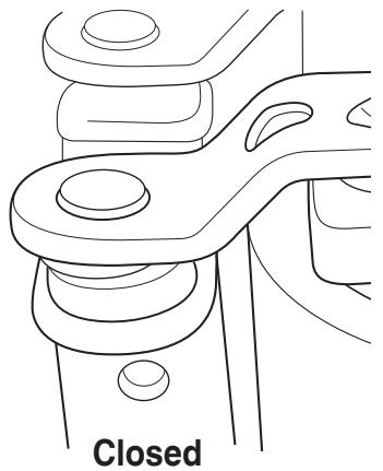
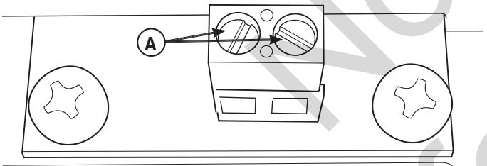
50 Amp Module: Relay contacts will be closed. Relay and communication LED's will be green. Appliance/load will have power.
Low Voltage Module (Single or Dual): Verify continuity across low voltage control wiring contacts (A). Communication LED will be green. Appliance/load will have power.
- Press the TEST button on the Symphony II system control board. The priority 1 LED and load connected to remote module set to priority 1 will turn OFF.
50 Amp Module: If off, relay LED status is off. Communication LED status is green.
Low Voltage Module (Single or Dual): If off, low voltage communication LED status is green. Continuity will not be measured across low voltage contacts.
The priority 2 LED (D) and load connected to remote module set to priority 2 will turn ON. Repeat step 4 for each priority number being managed.
- Each subsequent press of the TEST button cycles to the next lower priority, through priority 8. After priority 8, press TEST button one time to exit test mode.
The system will reset and be ready to add loads in 5 minutes.
- To return to utility power, turn the utility disconnect circuit breaker to the "ON" position. All managed loads will be turned off and turn back on after 5 minutes.
Controls
Other than a Manual Override lever, there are no operator controls because this is an automatic transfer switch. The manual override is to be used only by licensed professionals. Information on handle use can be obtained by calling Technical Service at 800-743-4115.
Operation
To select automatic transfer operation, do the following:
- In transfer switch, set utility disconnect circuit breaker to "ON" position.
- In transfer switch, set generator disconnect circuit breaker to "ON" position.
- Install 15 Amp fuse in generator's control panel.
- Set generator's circuit breaker to "ON" position.
- Set generator's system switch to "AUTO" position.
The system will now be in automatic operation mode.
When the generator is providing power to the transfer switch, the transfer switch control board is constantly monitoring generator power and communicating with the Symphony II system control board.
The Symphony II system will control up to 8 priorities, with priority 9 and 10 as lockouts. When total generator load meets a preset value, the Symphony II system control board will start shedding loads, starting with the lowest priority (highest number) load. The Symphony II system will add or shed managed loads based on the generator output capacity and priority settings.
The Symphony II system waits 10 seconds between adding or shedding each load to permit the system to stabilize. If too much load demand is seen, the Symphony II system will shed all managed loads quickly to prevent the generator from overloading. Once the load demand has stabilized, the Symphony II system will re-load the generator after a 5 minute delay, as described above.
There is a minimum five minute delay between the time utility power is lost and priority 1 loads are energized by the Symphony II system.
Be aware that managed heating element energy loads (such as electric range burners, oven, or space heaters) that were ON when utility power was lost, will be ON when the generator begins supplying power. It is advised that the owner check all such managed devices to ensure they are turned OFF before generator power appears.
Managed devices like clothes dryers that require pressing a START button will not resume operation unless the START button is pressed after generator power begins.
Symphony™ II Power Monitor (Optional)
For your convenience, a Symphony II Power Monitor is available, which provides a visual "on/off" status of each managed appliance/load. A series of LED lights are ON when an appliance has generator power and OFF when the appliance is in a shed mode or does not have power. When on generator power, the consumer can see which appliances are being managed.
A decal is provided that can be labeled with the managed appliances/loads and placed next to each priority LED.
The monitor is plugged into any convenient standard outlet within the home and constantly receives system status via the power line communication technology utilized by the Symphony II Power Management System during generator power.
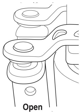
Enclosure Door
To open transfer switch door, press the spring-load door lock to the right and pull down on the door.
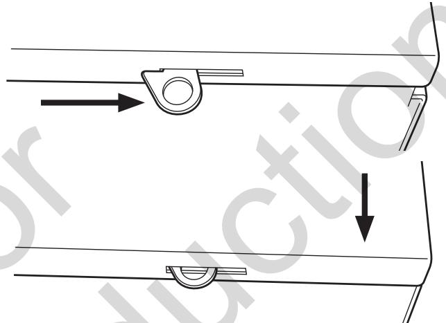
To close and latch door, push door closed against enclosure. While in this position, push door upwards. This will cause spring-load door lock to engage and latch door in place. Enclosure door MUST be closed and latched at all times except when system is being serviced.
Status LED's
Described below are the system's LED indicators and the conditions each LED color represents:
Transfer Switch Control Board
STATUS LED
RED (A) means GENERATOR power is present.
GREEN (B) means UTILITY power is present.
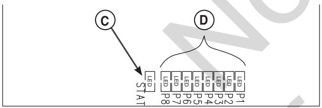
Symphony II System Control Board
STATUS LED (C)
Single Blink-Pause means unit is operating on GENERATOR power.
Double Blink-Pause means unit is operating on UTILITY power.
PRIORITY LIGHTS/LED's (D & G)
When green LED is lit, indicates that optional remote module set to that priority is supplying power to connected load during generator power.
When not lit, indicates that optional remote module set to that priority is set to OFF (being managed and Symphony II System is not allowing power to the unit).
All lights/LED's are OFF when utility power is present.
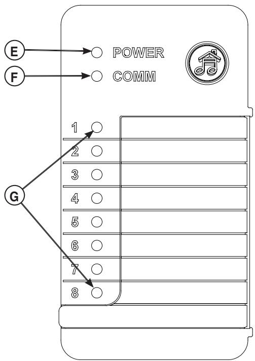
Symphony II Power Monitor (Optional)
POWER LIGHT (E)
When lit, indicates that monitor detects outlet power.
When not lit, indicates that no power is present at outlet.
COMM (communication status) LIGHT (F)
When lit, indicates that unit is receiving signals from the Symphony II controller.
When not lit, indicates that utility power is present or a fault in Symphony II controller.
System Lights

POWER Monitor ON

COMM Modules ACTIVE
Priority Lights 1-8

GREEN Power ON

NOT LIT Power OFF
*Possible 5 minute delay.
Blocked Items
Questions?
Call 800-743-4115
312113
Remote Module LED Status Indicators
Symphony II System does not communicate or manage appliances/loads when utility power is present.
NOTICE When looking at LED's, make sure you look straight on and not at an angle.
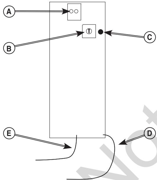
Low Voltage (Single and Dual) Models
A - Low Voltage Control Wiring Terminal Contacts
B - Priority Selector
C - Communication LED
D - Neutral Connection
E - Power/Line Connection
LED is for signal communication status (C).
Utility power present:
Normal State
- Orange LED - No communication and appliances/ loads cannot be managed by Symphony II System
- Problem State (see Troubleshooting)
- No LED - No power to low voltage control board; verify correct wiring
- Green LED - Broken LED; replace low voltage module
- Red LED - Fault in system; verify current transformer connections, verify terminations on orange and yellow communication wires
Generator power present:
Normal State
-
Green LED - Signal communication detected and appliances/loads can be managed after 5 minute delay
-
Problem State (see Troubleshooting)
-
No LED - No power to low voltage control board; verify correct wiring
- Orange LED - Signal communication not detected; verify correct wiring
- Red LED - Fault in system; verify current transformer connections, verify terminations on orange and yellow communication wires
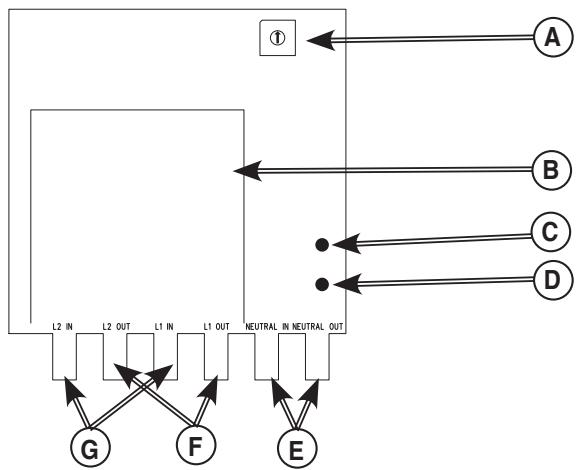
50 Amp Model
A - Priority Selector
B-50 Amp Relay
C - Relay Status LED
D - Signal Communication LED
E - Neutral Connection
F - Load Connection
G - Power/Line Connection
LED's are for signal communication status and relay position status.
Utility power present:
Normal State
Relay Position Status LED (C)
- Green LED - Relay is closed; power available to appliance/load
Signal Communication Status LED (D)
-
Orange LED - No communication and appliances/ loads cannot be managed by Symphony II System
-
Problem State (see Troubleshooting)
Relay Position Status LED (C)
- No LED - Power not available to managed appliance/load; 5 minute delay has not expired, verify correct wiring
- Red LED - 50 Amp relay contacts in incorrect state; replace 50 Amp module
Signal Communication Status LED (D)
- No LED - No power to 50 Amp control board; verify correct wiring
- Green LED - Broken LED; replace 50 Amp module
- Red LED - Fault in system; verify current transformer connections, verify terminations on orange and yellow communication wires
Generator power present:
Normal State
Relay Position Status LED (C)
- Green LED - Relay is closed; power available to appliance/load
- No LED - Relay open, no power, Symphony II is managing load
Signal Communication Status LED (D)
-
Green LED - Signal communication detected and appliances/loads are being managed after 5 minute delay
-
Problem State (see Troubleshooting)
Relay Position Status LED (C)
- No LED - Power not available to managed appliance/load; 5 minute delay has not expired, verify correct wiring
- Red LED - 50 Amp relay contacts in incorrect state; replace 50 Amp module
Signal Communication Status LED (D)
- No LED - No power to 50 Amp control board; verify correct wiring
- Orange LED - Signal communication not detected; verify correct wiring
- Red LED - Fault in system; verify current transformer connections, verify terminations on orange and yellow communication wires
Maintenance
The transfer switch is designed to be maintenance free under normal usage. However, inspection and maintenance checks should be made on a regular basis. Maintenance will consist mainly of keeping the transfer switch clean.
Visual inspections should be done at least three times each year. Access to the transfer switch and optional remote modules must not be obstructed. Keep 3 feet (92 cm) clearance around transfer switch. Check for an accumulation of dirt, moisture and/or corrosion on and around the enclosure, loose parts/hardware, cracks and/or discoloration to insulation, and damaged or discolored components.
Exercise the transfer switch and Symphony II system at least once every three months as described in Testing the Automatic Transfer Switch and in Testing the Symphony II Power Management System unless a power outage occurs and the entire home generator system has gone through an automatic sequence. Allow generator to run for at least 10 minutes during exercise cycle.
Contact a licensed electrical professional to inspect and clean the inside of the enclosure and other components of your home generator system at least once a year.
When Calling for Assistance
You must have the Model Number and Serial Number from each transfer switch or remote module ID label at hand if it is necessary to contact a local service center regarding service or repair. Obtain this information from the unit ID labels located on or inside device. For convenience, record the information on the inside front cover of this manual.
To contact Briggs & Stratton call 800-743-4115, between 8:00 AM and 5:00 PM CT.
Installation Inspection
Before placing the system into service, inspect the entire installation carefully.
Complete the "Installation Checklist" supplied with the generator as you make the inspection. Ensure all items have been filled-in and all signatures have been obtained. Instruct the owner to mail the white copy to the address shown on the checklist.
Troubleshooting
| Problem | Cause | Correction |
| Automatic transfer switch does not transfer to generator | 1.Generator breaker open.2.Generator voltage not acceptable.3.Generator disconnect circuit breaker open in transfer switch. | 1 Reset generator circuit breaker.2.Refer to generator manual.3.Rest generator disconnect circuit breaker in transfer switch. |
| Automatic transfer switch does not transfer to utility | 1. Utility disconnect circuit breaker open in transfer switch.2. Utility voltage not acceptable. | 1. Reset utility disconnect circuit breaker in transfer switch.2.Wait for utility voltage to return to normal. |
| Generator is still running after switch transfers to utility power | Engine cool down period. | Engine should stop after 1 minute. |
| Generator or supervised loads (air conditioner, etc.) are operating improperly when generator is supplying power | 1. Remote modules are not operating correctly.2. Too much load on generator.3. Current transformer not connected.4. Broken current transformer.5. Communication lost due to power line noise.6. Communication lost between transfer switch and Symphony II control boards. | 1. Five minute delay timer has not expired.2. Decrease load to generator.3. Contact local authorized service center.4. Contact local authorized service center.5. Verify fluorescent ballasts are rated for residential use only. If not, replace with residential ballast. Install noise filter in series and close to problematic device.Rewire remote module to opposite power line (L1 or L2) from that of problematic device.6. Contact local authorized service center. |
| Generator is still running after utility power is restored | 1. Minimum engine run time has not elapsed.2.Fuse(s) in transfer switch is defective. | 1. Wait five minutes for transfer switch to retransfer to utility power.2. Contact local authorized service center. |
| Relay modules do not close after five minutes | 1. Too much load on generator.2. Communication interruption.3.Priority set to 9 or 10. | 1. Decrease load to generator.2. Reset utility disconnect circuit breaker in transfer switch and wait five minutes (turn OFF breaker for ten seconds then turn it back ON).3.Appliance will not turn on during standby power. Contact local authorized service center to change priority setting. |
| Relay modules do not open during transfer and retransfer | Communication interruption. | Contact local authorized service center. |
| Symphony II system control board status LED does not change illumination blinking pattern for utility or generator power. | 1.TxRx and TxRx GND communication wires are not connected between the generator and transfer switch.2.TxRx and TxRx GND communication wires are connected incorrectly between the generator and transfer switch.3.TxRx and TxRx GND communication wires affected by electrical noise interference. | 1. Contact local authorized service center.2. Contact local authorized service center.3. Contact local authorized service center. |
Transfer Switch Schematic Diagram
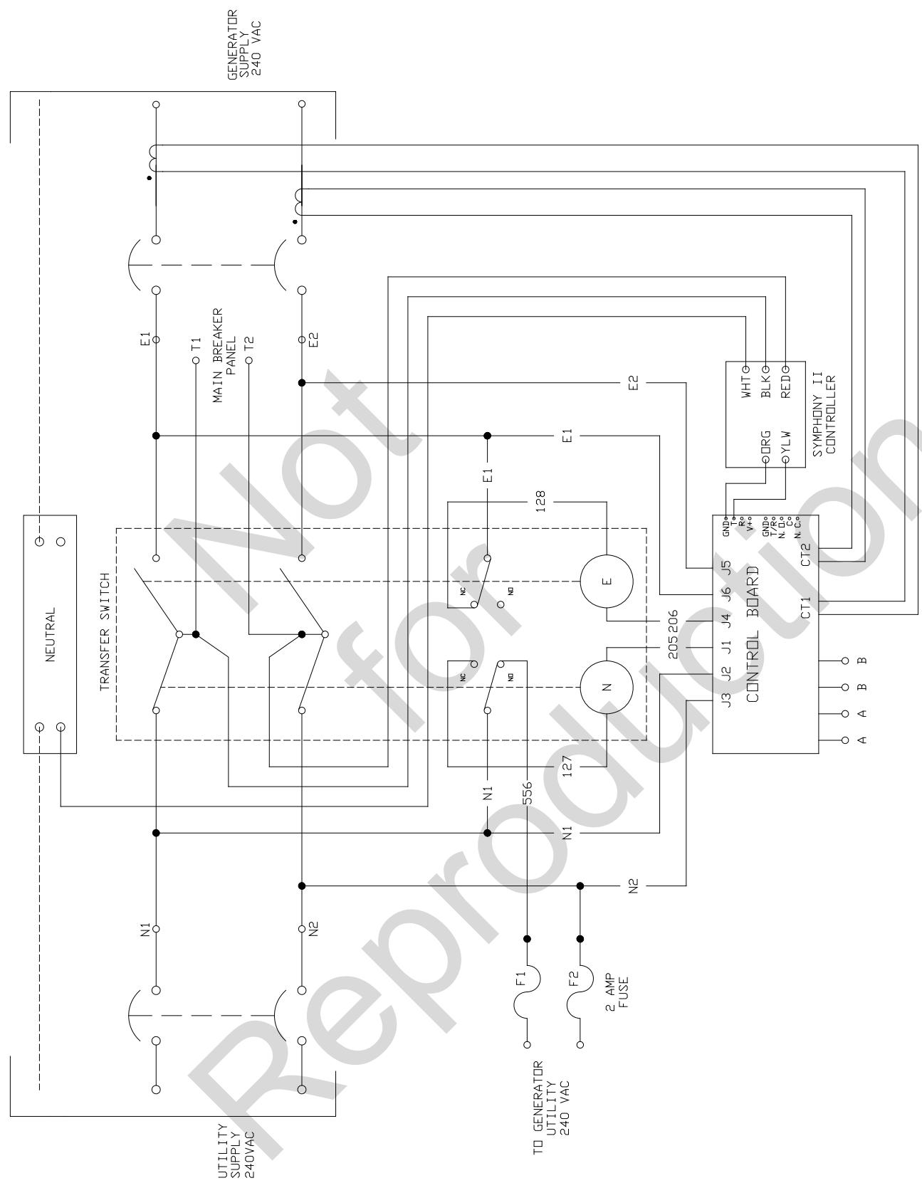
WIRE SCHEMA TIC
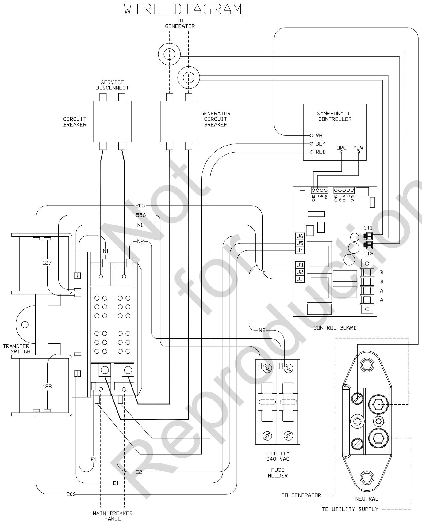
Transfer Switch Wiring Diagram
Effective November 1, 2005 replaces all undated Warranties and all Warranties dated before November 1, 2005
LIMITED WARRANTY
Briggs & Stratton Power Products Group, LLC will repair or replace, free of charge, any part(s) of the equipment that is defective in material or workmanship or both. Transportation charges on product submitted for repair or replacement under this warranty must be borne by purchaser. This warranty is effective for the time periods and subject to the conditions stated below. For warranty service, find the nearest Authorized Service Dealer in our dealer locator map at BRIGGSandSTRATTON.COM.
THERE IS NO OTHER EXPRESS WARRANTY. IMPLIED WARRANTY, INCLUDING THOSE OF MERCHANTABILITY AND FITNESS FOR A PARTICULAR PURPOSE, ARE LIMITED TO ONE YEAR FROM PURCHASE, OR TO THE EXTENT PERMITTED BY LAW. ANY AND ALL IMPLIED WARRANTY ARE EXCLUDING. LIABILITY FOR INCIDENTAL OR CONSEQUENTIAL DAMAGES ARE EXCLUDING TO THE EXTENT EXCLUSION IS PERMITTED BY LAW. Some states or countries do not allow limitations on how long an implied warranty lasts, and some states or countries do not allow the exclusion or limitation of incidental or consequential damages, so the above limitation and exclusion may not apply to you. This warranty gives you specific legal rights and you may also have other rights which vary from state to state or country to country.
WARRANTY PERIOD
Consumer Use
3 years
Commercial Use
None
The warranty period begins on the date of purchase by the first retail consumer or commercial end user, and continues for the period of time stated in the table above. "Consumer use" means personal residential household use by a retail consumer. "Commercial use" means all other uses, including use for commercial, income producing or rental purposes. Once equipment has experienced commercial use, it shall thereafter be considered as commercial use for purposes of this warranty. Equipment used for prime power in place of utility are not applicable to this warranty.
NO WARRANTY REGISTRATION IS NECESSARY TO OBTAIN WARRANTY ON BRIGGS & STRATTON PRODUCTS. SAVE YOUR PROOF OF PURCHASE RECEIPT. IF YOU DO NOT PROVIDE PROOF OF THE INITIAL PURCHASE DATE AT THE TIME WARRANTY SERVICE IS REQUESTED, THE MANUFACTURING DATE OF THE PRODUCT WILL BE USED TO DETERMINE THE WARRANTY PERIOD.
ABOUT YOUR WARRANTY
We welcome warranty repair and apologize to you for being inconvenienceed. Any Authorized Service Dealer may perform warranty repairs. Most warranty repairs are handled routinely, but sometimes requests for warranty service may not be appropriate. For example, warranty service would not apply if equipment damage occurred because of misuse, lack of routine maintenance, shipping, handling, warehousing or improper installation. Similarly, the warranty is void if the manufacturing date or the serial number on the equipment has been removed or the equipment has been altered or modified. During the warranty period, the Authorized Service Dealer, at its option, will repair or replace any part that, upon examination, is found to be defective under normal use and service. This warranty will not cover the following repairs and equipment:
- Normal Wear: Outdoor Power Equipment, like all mechanical devices, needs periodic parts and service to perform well. This warranty does not cover repair when normal use has exhausted the life of a part or the equipment.
Installation and Maintenance: This warranty does not apply to equipment or parts that have been subjected to improper or unauthorized installation or alteration and modification, misuse, negligence, accident, overloading, improper maintenance, repair or storage so as, in our judgment, to adversely affect its performance and reliability. This warranty also does not cover normal maintenance such as adjustments, cleaning and fuse replacement.
Other Exclusions: This warranty excludes wear items or damage or malfunctions resulting from accidents, abuse, modifications, alterations, or improper servicing. Accessory parts are excluded from the product warranty. This warranty excludes failures due to acts of God and other force majeure events beyond the manufacturers control. Also excluded is used, reconditioned, and demonstration equipment. 198180E, Rev. C, 12/31/2006
BRIGGS & STRATTON POWER PRODUCTS GROUP, LLC
MILWAUKEE, WI, USA
Reserved
Automatic Transfer Switch
Product Specifications
Model 071048
Rated Maximum Load Current (at 25^ / 77^ . 100 Amps
Rated AC Voltage 250 Volts
Poles. 2
Frequency. 60 Hz
Fault Current Rating .... 25,000 RMS Symmetrical Amperes
Normal Operating Range.....-20°F (-28.8°C) to 104°F (40°C)
Weight 59 lbs. (27 kg)
Model 071049
Rated Maximum Load Current (at 25^ / 77^ . 200 Amps
Rated AC Voltage 250 Volts
Poles. 2
Frequency 60 Hz
Fault Current Rating ...... 25,000 RMS Symmetrical Amperes
Normal Operating Range.....-20°F (-28.8°C) to 104°F (40°C)
Weight 63 lbs. (28 kg)
This transfer switch is a UL Listed device
Model 071054
Rated Maximum Load Current (at 25^ / 77^ ). 200 Amps
Rated AC Voltage 250 Volts
Poles. 2
Frequency. 60 Hz
Fault Current Rating ...... 25,000 RMS Symmetrical Amperes
Normal Operating Range.....-20°F (-28.8°C) to 104°F (40°C)
Weight .63 lbs (27 kg).
Copyright © 2011. Briggs & Stratton Power Products Group, LLC
*Possible 5 minute delay.
Blocked Items
Questions?
Call 800-743-4115
312113
You've asked des questions?
Poids. 27 kg (59 lb)
Modèle 071049
Charge nominale maximum à 25^ (77^)^* 200 Ampères
Tension nominale C.A. 250 Volts
Poles. 2
Fréquence 60 Hz
Poids. 28 kg (63 lb)
Poids. 28 kg (63 lb)

- Installation & Operator's Manual
- 100/200 Amp Automatic Transfer Switch
- with Service Disconnect and Symphony™ II Power Management System
- Where to Find Us
- For Future Reference
- Table of Contents
- Important Safety Instructions 4
- Installation 5
- Controls 16
- Operation 16
- Maintenance. 20
- Troubleshooting 21
- Warranty 24
- Product Specifications. 26
- Save These Instructions
- Important Safety Instructions
- Safety Symbols and Meanings
- Installation
- Home Owner Responsibilities
- Owner Orientation
- These factors will have a direct effect on the overall price of your equipment installation.
- Installing Dealer/Contractor Responsibilities
- Equipment Description
- Delivery Inspection
- Shipment contents:
- Optional components:
- To be supplied by installer:
- Mounting Guidelines
- Power Wiring Interconnections
- Supervisory Control Terminals
- System Setup
- Setting Dipswitches
- Remote Module Setup
- Testing the Automatic Transfer Switch
- Utility Fail
- Engine Warm-Up
- Transfer
- Load Management
- Utility Pickup
- Retransfer
- Engine Cool Down
- Testing the Symphony™ II Power Management System
- The test procedure in generator mode is as follows:
- Controls
- Operation
- Symphony™ II Power Monitor (Optional)
- Enclosure Door
- Status LED's
- Remote Module LED Status Indicators
- Utility power present:
- Generator power present:
- Maintenance
- When Calling for Assistance
- Installation Inspection
- Transfer Switch Schematic Diagram
- LIMITED WARRANTY
- WARRANTY PERIOD
- ABOUT YOUR WARRANTY
- Automatic Transfer Switch
- Product Specifications
- Model 071048
- Model 071049
- Model 071054
- Blocked Items
- Questions?
- Modèle 071049
Brand : GENERAL ELECTRIC
Model : 100 AMP AUTOMATIC TRANSFER SWITCH
Category : Energy transfer automatic