
CS-02 - Audio Mixer GEMINI - Free user manual and instructions
Find the device manual for free CS-02 GEMINI in PDF.


| Product type | 5-channel professional audio mixer with built-in effects |
| Brand | GEMINI |
| Model | CS-02 |
| Number of channels | 5 stereo channels + 3 microphone inputs |
| Microphone inputs | 1 XLR/6.35mm combo jack (front) + 2 6.35mm jacks (rear) |
| Line inputs | 10 RCA line inputs (including 3 switchable Phono/Line) |
| Phono inputs | 3 RCA phono inputs (switchable with line) |
| Main outputs | Balanced XLR master + unbalanced RCA master + -10/-20 dB attenuation |
| Auxiliary outputs | Booth/zone RCA output, zone RCA output, record RCA output |
| Effects processor | 25 DSP effects with blue LCD display, 5 memories, Dry/Wet control |
| BPM function | Automatic and manual (Tap) calculator with tempo sync |
| Equalization | 3-band parametric (treble, mid, bass) per channel ±12 dB |
| Crossfader | Replaceable (compatible RG-45/RG-45PRO), adjustable curve, per-channel assignment |
| Channel faders | 30mm linear, replaceable |
| VU meters | Pre-fader per channel (LED), LED master |
| Talkover function | Automatic source attenuation when using microphone 1 |
| Headphone output | 6.35mm jack with volume, CUE/PGM selection, Split Cue function |
| Power supply | 115/230V AC selector, fuse, on/off switch |
| Rack mounting | 19" rack mount kit included (brackets and screws) |
| Safety instructions | Overcurrent protection, grounding, ventilation |
| Maintenance | Cleaning with a slightly damp cloth, no corrosive products |
| Spare parts | Crossfader (RG-45/RG-45PRO), channel fader (072-127), knobs, ground terminal |
| Repairability | Repair by customer service only, no user-serviceable parts |
| Warranty | Manufacturer's warranty, return to dealer with invoice |
Frequently Asked Questions - CS-02 GEMINI
User questions about CS-02 GEMINI
0 question about this device. Answer the ones you know or ask your own.
Ask a new question about this device
Download the instructions for your Audio Mixer in PDF format for free! Find your manual CS-02 - GEMINI and take your electronic device back in hand. On this page are published all the documents necessary for the use of your device. CS-02 by GEMINI.
USER MANUAL CS-02 GEMINI
Gemini Sound Products Corp.
Worldwide Headquarters
120 Clover Place
Edison, New Jersey 08837
Ph: 732.738.9003
Fax: 732.738.9006
UK:
Gemini Sound Products LTD
Unit C4 Hazleton
Industrial Estate,
Waterlooville P08 9JU
Ph: +44 (0)87 087 00880
Fax: +44 (0)87 087 00990
Spain:
Gemini Sound Products S.A.
Rosellon 516 local
08026 Barcelona
Ph: +34 93 436 37 00
Fax: +34 93 347 69 61
[Non-Text]
France:
GSL France
1, Allée d' Effiat,
Parc de l'événement
F-91160 Longjumeau
Ph: +33 1 69 79 97 70
Fax: +33 1 69 79 97 80
Germany:
Gemini Sound
Products GmbH
Liebigstrasse 16
85757 Karlsfeld
Ph: +49 8131 39171-0
Fax: +49 8131 39171-8
In the USA: If you experience problems with this unit, please go to http://www.geminidj.com/support.html or call 1-732-738-9003 for Gemini Customer Service. Do not attempt to return this equipment to your dealer. Gemini stands behind their products with a 1 year limited warranty on all audio products. For larger images & detailed specs visit our website @ http://www.geminidj.com. WE ARE NOT RESPONSIBLE FOR TYPOGRAPHICAL ERRORS OR OMISSIONS. WE RESERVE THE RIGHT TO CHANGE WITHOUT NOTICE. Parts of the design of this product may be protected by worldwide patents. Information in this manual is subject to change without notice and does not represent a commitment on the part of the vendor. Gemini Sound Products Corp. shall not be liable for any loss or damage whatsoever arising from the use of information or any error contained in this manual. No part of this manual may be reproduced, stored in a retrieval system or transmitted, in any form or by any means, electronic, electrical, mechanical, optical, chemical, including photocopying and recording, for any purpose without the express written permission of Gemini Sound Products Corp. It is recommended that all maintenance and service on this product is performed by Gemini Sound Products Corp. or its authorized agents. Gemini Sound Products Corp. will not accept liability for loss or damage caused by maintenance or repair performed by unauthorized personnel.
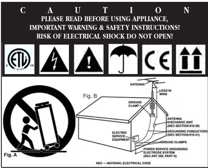
CAUTION: This product satisfies FCC regulations when shielded cables and connectors are used to connect the unit to other equipment. To prevent electromagnetic interference with electric appliances such as radios and televisions, use shielded cables and connectors for connections.
The exclamation point within an equilateral triangle is intended to alert the user to the presence of important operating and maintenance (servicing) instructions in the literature accompanying the appliance.
The lightning flash with arrowhead symbol, within an equilateral triangle, is intended to alert the user to the presence of uninsulated "dangerous voltage" within the product's enclosure that may be of sufficient magnitude to constitute a risk of electric shock to persons.
READ INSTRUCTIONS: All the safety and operating instructions should be read before the product is operated.
RETAIN INSTRUCTIONS: The safety and operating instructions should be retained for future reference.
HEED WARNINGS: All warnings on the product and in the operating instructions should be adhered to.
FOLLOW INSTRUCTIONS: All operating and use instructions should be followed.
CLEANING: The product should be cleaned only with a polishing cloth or a soft dry cloth. Never clean with furniture wax, benzine, insecticides or other volatile liquids since they may corrode the cabinet.
ATTACHMENTS: Do not use attachments not recommended by the product manufacturer as they may cause hazards.
WATER & MOISTURE: Do not use this product near water, for example, near a bathtub, wash bowl, kitchen sink, or laundry tub; in a wet basement; or near a swimming pool; and the like.
ACCESSORIES: Do not place this product on an unstable cart, stand, tripod, bracket, or table. The product may fall, causing serious injury to a child or adult, and serious damage to the product. Use only with a cart, stand, tripod, bracket, or table recommended by the manufacturer, or sold
with the product. Any mounting of the product should follow the manufacturer's instructions, and should use a mounting accessory recommended by the manufacturer.
CART: A product and cart combination should be moved with care. Quick stops, excessive force, and uneven surfaces may cause the product and cart combination to overturn. SEE FIGURE A.
VENTILATION: Slots and openings in the cabinet are provided for ventilation and to ensure reliable operation of the product and to protect it from overheating, and these openings must not be blocked or covered. The openings should never be blocked by placing the product on a bed, sofa, rug, or other similar surface. This product should not be placed in a built-in installation such as a bookcase or rack unless proper ventilation is provided or the manufacturer's instructions have been adhered to.
POWER SOURCES: This product should be operated only from the type of power source indicated on the marking label. If you are not sure of the type of power supply to your home, consult your product dealer or local power company.
LOCATION: The appliance should be installed in a stable location.
NON-USE PERIODS: The power cord of the appliance should be unplugged from the outlet when left unused for a long period of time.
GROUNDING OR POLARIZATION:
- If this product is equipped with a polarized alternating current line plug (a plug having one blade wider than the other), it will fit into the outlet only one way. This is a safety feature. If you are unable to insert the plug fully into the outlet, try reversing the plug. If the plug should still fail to fit, contact your electrician to replace your obsolete outlet. Do not defeat the safety purpose of the polarized plug.
- If this product is equipped with a three-wire grounding type plug, a plug having a third (grounding) pin, it will only fit into a grounding type power outlet. This is a safety feature. If you are unable to insert the plug into the outlet, contact your electrician to replace your obsolete outlet. Do not defeat the safety purpose of the grounding type plug.
POWER-CORD PROTECTION: Power-supply cords should be routed so that they are not likely to be walked on or pinched by items placed upon or against them, paying particular attention to cords at plugs, convenience receptacles, and the point where they exit from the product.
OUTDOOR ANTENNA GROUNDING: If an outside antenna or cable system is connected to the product, be sure the antenna or cable system is grounded so as to provide some protection against voltage surges and built-up static charges. Article 810 of the National Electrical Code, ANSI/NFPA 70, provides information with regard to proper grounding of the mast and supporting structure, grounding of the lead-in wire to an antenna discharge unit, size of grounding conductors, location of antenna-discharge unit, connection to grounding electrodes, and requirements for the grounding electrode. SEE FIGURE B.
LIGHTNING: For added protection for this product during a lightning storm, or when it is left unattended and unused for long periods of time, unplug it from the wall outlet and disconnect the antenna or cable system. This will prevent damage to the product due to lightning and power-line surges.
POWER LINES: An outside antenna system should not be located in the vicinity of overhead power lines or other electric light or power circuits, or where it can fall into such power lines or circuits. When installing an outside antenna system, extreme care should be taken to keep from touching such power lines or circuits as contact with them might be fatal.
OVERLOADING: Do not overload wall outlets, extension cords, or integral convenience receptacles as this can result in a risk of fire or electric shock.
OBJECT & LIQUID ENTRY: Never push objects of any kind into this product through openings as they may touch dangerous voltage points or short-out parts that could result in a fire or electric shock. Never spill liquid of any kind on the product.
SERVICING: Do not attempt to service this product yourself as opening or removing covers may expose you to dangerous voltage or other hazards. Refer all servicing to qualified service personnel.
DAMAGE REQUIRING SERVICE: Unplug this product from the wall outlet and refer servicing to qualified service personnel under the following conditions:
- When the power-supply cord or plug is damaged.
- If liquid has been spilled, or objects have fallen into the product.
- If the product has been exposed to rain or water.
- If the product does not operate normally by following the operating instructions. Adjust only those controls that are covered by the operating instructions as an improper adjustment of other controls may result in damage and will often require extensive work by a qualified technician to restore the product to its normal operation.
- If the product has been dropped or damaged in any way.
- When the product exhibits a distinct change in performance, this indicates a need for service.
REPLACEMENT PARTS: When replacement parts are required, be sure the service technician has used replacement parts specified by the manufacturer or have the same characteristics as the original part. Unauthorized substitutions may result in fire, electric shock, or other hazards.
SAFETY CHECK: Upon completion of any service or repairs to this product, ask the service technician to perform safety checks to determine that the product is in proper operating condition.
WALL OR CEILING MOUNTING: The product should not be mounted to a wall or ceiling.
HEAT: The product should be situated away from heat sources such as radiators, heat registers, stoves, or other products (including amplifiers) that produce heat.
DISPOSAL: This product shall not be treated as household waste. Instead it shall be handed over to the applicable collection point for the recycling of electrical and electronic equipment. By ensuring this product is disposed of correctly, you will help prevent potential negative consequences for the environment and human health, which could otherwise be caused by inappropriate waste handling of this product. The recycling of materials will help to conserve natural resources. For more detailed information about recycling of this product, please contact your local city office, your household waste disposal service or the shop where you purchased the product.
Face
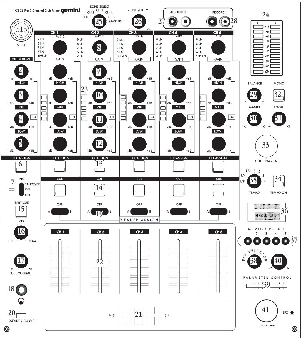
To avoid confusion, controls that are duplicated for each channel are labeled only once.
Parts Checklist:
CS-02 Unit
AC Power Cable
Rack Ears
Screws for Attaching Rack Ears
Manual with Warranty Info
-
XLR-1/4" Combo Mic 1 Input
-
Mic 1 Volume Control
-
Mic 1 High Band EQ
-
Mic 1 Mid Band EQ
-
Mic 1 Low Band EQ
-
Mic 1 EFX Assign Button
-
Mic 1 On/Off/Talkover Switch
-
Device/Channel Assign Knob
-
Channel Gain Control
-
Channel High Band EQ
-
Channel Mid Band EQ
-
Channel Low Band EQ
-
Channel EFX Assign Button
-
Channel CUE Selector
-
Split Cue Button
-
CUE/PGM Rotary Control
-
Cue Volume Control
-
Headphone Output
-
X-Fader Assign Switch
-
X-Fader Curve Switch
-
X-Fader
-
Channel Volume Fader
-
Channel LED VU Meter
-
Master LED VU Meter
-
Zone Select Control
-
Zone Volume
-
Auxiliary RCA Inputs
-
Record RCA Outputs
-
Balance Control
-
Master Volume Control
-
Booth Volume Control
-
Mono Output Switch
-
Auto BPM/Tap Button
-
EFX-Tempo Sync On/Off
-
Tempo Ratio Selector
-
LCD Parameter Display
-
Memory Recall Banks
-
EFX Program Selector
-
EFX Parameter Control
-
EFX Dry/Wet Control
-
EFX On/Off Button
Rear
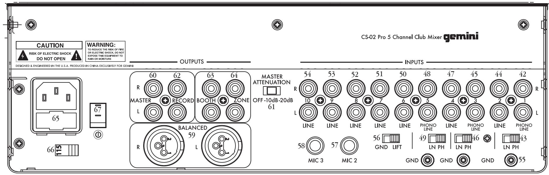
Input Section:
- Phono/Line #1 RCA Input
- Phono/Line #1 Selection Switch
- Line #2 RCA Input
- Phono/Line #3 RCA Input
- Phono/Line #3 Selection Switch
- Line #4 RCA Input
- Phono/Line #5 RCA Input
- Phono/Line #5 Selection Switch
- Line #6 Input
- Line #7 Input
-
Line #8 Input
-
Line #9 Input
- Line #10 Input
- Ground Terminals
- Ground Lift Switch
- Mic #2 1/4" Input
- Mic #3 1/4" Input
Output Section:
- Balanced XLR Master Outputs
- Master RCA Outputs
- Master Volume Attenuation Switch
- Record RCA Outputs
- Booth RCA Outputs
- Zone RCA Outputs
Power Section:
- AC Power Inlet w/Fuse
- Voltage Selection Switch
- Power Switch
CS-02 PROFESSIONAL 5-CHANNEL STEREO FX MIXER
INTRODUCTION:
Congratulations on your purchase of a Gemini CS-02 Professional 5-Channel Stereo FX Mixer. The CS-02 will exceed your expectations for a DJ mixer, with premium sound quality and a wealth of useful features. With proper care and maintenance, your mixer will provide years of reliable performance.
FEATURES:
- 5 Channels with pre-fader LED VU meters and 3-band rotary EQ
- 3 Mic, 10 Line, and 3 Phono/Line Convertible Inputs
- Master, Booth, Zone, and Record RCA outputs w/ Zone device selection control
- 25 Channel-Assignable DSP effects with bright blue backlit LCD display and 5-bank memory recall
- 6-Device Input routing matrix on each channel
- 30mm linear DSP parameter control
- Rotary Dry/Wet control
- Auto & Tap BPM counter with optional EFX tempo synchronization
- Faceplate-mounted RCA Rec Output and Aux Input
- Dedicated faceplate-mounted 14 " XLR combo mic input with 3-band EQ and Talkover Function
- Master, Booth, and Zone outputs with independent rotary volume controls
- XLR Master Balanced Output with master attenuation switch
- Balance control with Mono switch
- Push button Cue Section with CUE/PGM control & Split Cue function
- Large blue backlit EFX On/Off button
- Replaceable faders with X-Fader Curve Control
- X-Fader assignment on each audio input channel
- Dual VU master meters
- 19" Rack ears included
CAUTIONS:
- All operating instructions should be read before using this equipment.
- To reduce the risk of electrical shock, do not open the unit. There are NO USER REPLACEABLE PARTS INSIDE. Please refer servicing to a qualified Gemini Sound Products service technician. In the USA: If you experience problems with this unit, please call 1 (732) 738-9003 for Gemini Customer Service. Do not attempt to return this equipment to your dealer.
- Do not expose this unit to direct sunlight or to a heat source such as a radiator or stove. When operating, ensure that the unit has adequate ventilation.
- This unit should be cleaned only with a damp cloth. Avoid solvents or other cleaning detergents.
- When moving this equipment, it should be placed in its original carton and packaging. This will reduce the risk of damage during transit.
6. DO NOT EXPOSE THIS UNIT TO RAIN OR MOISTURE.
7. DO NOT USE ANY SPRAY CLEANER OR LUBRICANT ON ANY CONTROLS OR SWITCHES.
CONNECTIONS / SETUP:



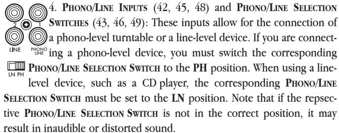

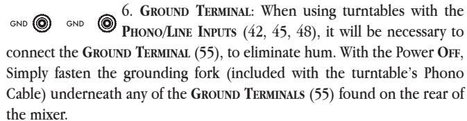
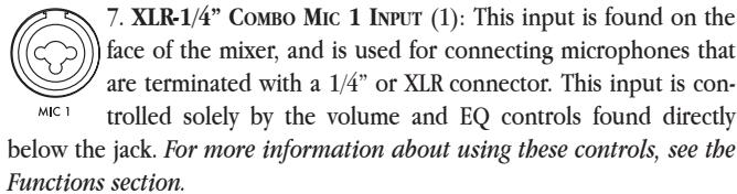

is ground. The MASTER VOLUME CONTROL (30) determines the level of audio which is sent to these outputs.


This is useful for situations where the output voltage of the mixer needs to be adjusted for use with certain PA and recording setups. By default, it is OK to leave the MASTER VOLUME ATTENUATION SWITCH in the 'OFF' position. If you notice that the output seems overdriven, or that the maximum volume level that you wish to achieve is reached before the MASTER LED VU METER (24) approaches 0dB, you may move the MASTER VOLUME ATTENUATION SWITCH to the '-10dB' or '-20dB' position.

- GROUND LIFT SWITCH (56): This switch lifts the signal ground, GND LIFT and may help in the event of a stubborn ground loop issue. Using the GROUND LIFT SWITCH is in no way a substitute for proper wiring, but in a live scenario, it can help to eliminate ground hum. Before changing the position of the switch, make sure to turn the unit Off. If both 'GND' and 'LIFT' settings sound identical, then keep the switch set to 'GND'. FUNCTIONS:
MIC VOLUME 1. MIC VOLUME (2): This rotary control alters the volume of the


the con control nal.


cies, wh position made to


the con control nal.


that the is exting effect.


the mic heard o


itself is assigned 5 of wh DEVICE/


- HEADPHONE OUTPUT (18): This jack accepts a standard 1/4" (6.35mm) connector, and will power virtually any headphones. OFF
-
X-FADER ASSIGN SWITCH (19): These switches, which are found on each channel, are used to assign each respective audio channel to either the left side (A) or the right side (B) of the X-FADER (21). When the switch is in the middle position (Off), the audio of each channel will be controlled solely by the CHANNEL VOLUME FADER (22), and not by the X-FADER (21).
-
X-FADER CURVE SWITCH (20): This switch determines the X-FADER CURVE taper of the X-FADER (21). When the switch is set to the left (gradual taper), the X-FADER (21) will have a smooth and gradual response which is best suited towards mixing. When the switch is set to the right (short taper), the X-FADER (21) will have a sharper response which is best suited towards scratch and battle use. For an even sharper response, replace the stock fader with an RG-45PRO Scratch Fader (sold separately).
-
X-FADER (21): With this control, you can fade between all of the active channels that are assigned to the 'A' side of the X-FADER and the active channels that are assigned to the 'B' side of the X-FADER. Assigning channels to the X-FADER is accomplished using the X-FADER ASSIGN SWITCHES (19).
-
CHANNEL VOLUME FADER (22): These controls, found on each channel, allow you to control the amount of signal that is sent to the output of the mixer.
-
CHANNEL LED VU METER (23): This VU meter displays the prefader level of the audio source. This has a multitude of uses, such as visually verifying which channels are receiving audio signal or matching the volume levels between two sources. For optimal sound, you should adjust the CHANNEL GAIN CONTROLS (9) until the CHANNEL LED VU METER begins to light the first blue LED.
-
MASTER LED VU METER (24): This VU meter displays the level of the signal being output through the MASTER OUTPUTS of the mixer. For optimal sound, this should not exceed +5dB on the meter.
-
ZONE SELECT CONTROL (25): By using this control, you can select a source to be output directly to the ZONE RCA OUTPUTS (64) found on the rear panel of the mixer. The audio signal output will be completely prefader, which means that the CHANNEL VOLUME FADER (22) has no effect on the level of the output. However, the audio will still be affected by the CHANNEL GAIN CONTROL (9) and CHANNEL EQS (10, 11, 12). When the ZONE SELECT CONTROL is set to Master, the ZONE RCA OUTPUTS (64) will behave the same as the BOOTH RCA OUTPUTS (63).
-
ZONE VOLUME (26): This rotary control determines the volume of the audio being sent out through the ZONE RCA OUTPUTS (64).
-
BALANCE CONTROL (29): This control allows you to pan the Master signal from Left to Right. By default, this control should be in the middle position, which is an equal balance of left and right channels.
-
MASTER VOLUME CONTROL (30): This rotary control determines the volume of the audio being sent out through the MASTER OUTPUTS (59, 60).
-
BOOTH VOLUME CONTROL (31): This rotary control determines the volume of the audio being sent out through the BOOTH RCA
MONO OUTPUTS (63).
-
Mono OUTPUT SWITCH (32): This switch toggles whether the MASTER OUTPUTS (59, 60) will be in Mono or Stereo.
-
AUTO BPM/TAP BUTTON (33): This button controls the BPM detection engine. By pressing and holding this button for 1 seconds, the unit will attempt to automatically detect the beats per minute of the audio channel which is selected via the CHANNEL EFX ASSIGN BUTTON (13). If there is no channel selected, the unit will attempt to detect the BPM of the Master signal. If the unit is not able to accurately detect the BPM, you may tap the AUTO BPM/TAP BUTTON in time to the music until the correct BPM is displayed on the LCD PARAMETER DISPLAY (36). To show the BPM at any time, press the AUTO BPM/TAP BUTTON (33) momentarily, and it will again be displayed on the LCD PARAMETER DISPLAY (36). When the letters 'A BPM' are displayed with the beats per minute, it indicates that the value displayed was automatically detected. When the letters 'T BPM' are displayed with the beats per minute, it indicates that the value displayed was calculated via the TAP function.
-
EFX-TEMPO SYNC ON/OFF (34): When this feature is turned on, any effects that can be synchronized to tempo will be linked to the tempo that is set via the AUTO BPM/TAP BUTTON (33).
-
TEMPO RATIO SELECTOR (35): This selector controls the ratio of the tempo that is set via the AUTO BPM/TAP BUTTON (33). When the control is set to any other value other than 1 (1:1 ratio), the tempo will be multiplied by that value. For instance, if a track is 125 beats per minute, then switching the TEMPO RATIO SELECTOR to 2 would be a 2:1 ratio, and the effect would be applied at 250 beats per minute. If the TEMPO RATIO SELECTOR is set to 1/2, it would be a 1:2 ratio, which means the effect would be applied at 62.5 beats per minute.
-
LCD PARAMETER DISPLAY (36): This blue backlit display shows the effect name and parameter that is relative to the effect. It also shows the detected BPM, when applicable.
MEMORY RECALL 35. MEMORY RECALL BANKS (37): These banks are useful for memorizing effect settings during a performance. By pressing and holding any one of the numbered buttons for 2 seconds, you can memorize all of the effects settings that are currently in place, including Channel, BPM, Tempo Ratio, Tempo Sync On/Off, Parameter, and EFX On/Off. Once you have memorized settings into a recall bank, it can be recalled by simply pressing the button momentarily.
- EFX PROGRAM SELECTOR (38): This rotary control selects the DSP effect which will be applied to the audio, when engaged.
-
EFX PARAMETER CONTROL (39): This slide control allows you to alter the parameter associated with the DSP effect.
-
EFX DRY/WET CONTROL (40): This rotary control allows you to alter how much of the audio signal is sent through the DSP effects section. For less intense effects, turn the control towards 'Dry'. For more intense effects, turn the control towards 'Wet'.

- EFX ON/OFF BUTTON (41): By pressing this button, the DSP effect that is selected is turned On or Off.
REPLACING THE X-FADER AND CHANNEL FADERS:
- Remove the black brushed aluminum plate which outlines the Channel and X-Fader section. The screws can be found at each corner of this plate.
-
To remove a channel fader, simply remove the two screws on the top and bottom of the fader. Disconnect the connector which plugs into the bottom of the fader, and replace it with a new fader. Verify that the fader is facing the appropriate direction before screwing it back in.
-
To replace the X-Fader, first unscrew the two outermost screws from the X-Fader, and disconnect the connector which plugs into the bottom of the fader. Remove the two innermost screws on the front of the fader, to remove the steel limiting plate. Attach the limiting plate to the new replacement X-Fader (model RG-45 or RG-45PRO). Then, replace the connector which plugs into the bottom of the fader, and replace the fader in the appropriate direction before screwing it back in.
USER REPLACEABLE PARTS:
User replaceable parts are listed below, and may be obtained by calling your nearest Gemini office, listed on the back cover page of this manual.
CROSSEADER: RG45 OR RG-45PRO
CHANNEL FADER: 072-127
CHANNEL AND X-FADER KNOB: 002-742
PARAMETER CONTROL FADER KNOB: 002-741
GROUND TERMINAL: 146-710
SPECIFICATIONS
Inputs:
Phono....3 mV, 47 KOhm
Line....150 mV, 27 KOhm
MIC 1, MIC 2, MIC 3....1.5 mV, 1 K Ohm Balanced
MIC 1 High....± 12dB
MIC 1 Mid....± 12dB
MIC 1 Low....± 12dB
Talkover Attenuation....-16dB
Outputs:
Master/Zone/Booth RCA....0 dB 1V, 400 Ohm
Max....20V Peak-to-Peak
Record....225 mV, 5 KOhm
Balanced Master....2V, 400 Ohm
General:
Frequency Response....20Hz - 20KHz +/- 2 dB
Distortion....< 0.02%
S/N Ratio......Better Than 80 dB
Headphone Impedance....16 Ohm
Power Source....115/230V, 60/50Hz, 20W
WEIGHTS AND DIMENSIONS:
Dimensions: 12.5 x 4.2 x 14" (318 x 107 x 356 mm)
Unit Weight: 12 lbs (5.44 kg)
Specifications and design are subject to change without notice for purpose of improvement.
*The stated warranty does not affect statutory local warranties
OPTIONAL ACCESSORIES:

natural_image
Top-down view of a DJX-05 headphones with black and silver earbuds (no text or symbols on the headset body)DJX-05 Professional Monitoring Headphones
natural_image
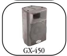
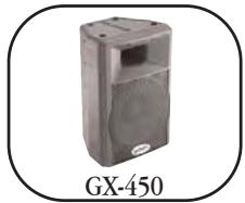
Exterior view of a GX-450 electronic device casing (no text or symbols on the device itself)GX-450 Powered ABS Loudspeakers
For more information on new and exciting Gemini products, visit our website at http://www.geminidj.com!
NOTES:
A C H T U N G !
BITTE UNBEDINGT VOR BENUTZUNG DES GERÄTS LESEN!
natural_image
Close-up of a DJX-05 headphones with black earbuds and metallic headband (no text or symbols on the device itself)natural_image
Exterior view of a GX-450 electronic device casing (no text or symbols on the body)To avoid confusion, controls that are duplicated for each channel are labeled only once.
natural_image
Top-down view of a DJX-05 headphones with black and silver earbuds (no text or symbols on the headset body)DJX-05 Auriculares Profesionales Monitor
natural_image
Exterior view of a gray rectangular electronic device labeled GX-450 (no other text or symbols visible)GX-450 Altavoces autoamplificados ABS
CONNEXIONS / MISE EN PLACE:
Talkover (Atténuation)....-16dB
Sorties:
Master/Zone/Booth(Cabine) RCA....0 dB 1V, 400 Ohms
Alimentation....115/230V, 60/50Hz, 20W
POIDS & DIMENSIONS:
Dimensions: 12.5 x 4.2 x 14" (318 x 107 x 356 mm)
Poids de l'Appareil: 12 lbs (5.44 kg)
natural_image
Close-up of a black and silver headboard耳机 with 'DJX-05' text label (no other visible text or symbols)ACCESSOIRES EN OPTION:
natural_image
Exterior view of a gray rectangular electronic device labeled GX-450 (no other text or symbols visible)WARRANTY AND REPAIR:
All Gemini products are designed and manufactured to the highest standards in the industry. With proper care and maintenance, your product will provide years of reliable service.
LIMITED WARRANTY
A. Gemini warrants its products to be free from defects in materials and workmanship for One (1) year from the original purchase date. Exceptions: Laser assemblies on CD Players, cartridges, and crossfaders are covered for 90 days.
B. This limited warranty does not cover damage or failure caused by abuse, misuse, abnormal use, faulty installation, improper maintenance or any repairs other than those provided by an authorized Gemini Service Center.
C. There are no obligations of liability on the part of Gemini for consequential damages arising out of or in connection with the use or performance of the product or other indirect damages with respect to loss of property, revenues, of profit, or costs of removal, installation, or reinstallation. All implied warranties for Gemini, including implied warranties for fitness, are limited in duration to One (1) year from the original date of purchase, unless otherwise mandated by local statutes.
RETURN/REPAIR
A. In the U.S.A., please call our helpful Customer Service Representatives at (732)738-9003, and they will be happy to give you a Return Authorization Number (RA#) and the address of an authorized service center closest to you.
B. After receiving an RA#, include a copy of the original sales receipt, with defective product and a description of the defect. Send by insured freight to: Gemini Sound Products Corp, and use the address provided by your customer service representative. Your RA# must be written on the outside of the package, or processing will be delayed indefinitely!
C. Service covered under warranty will be paid for by Gemini and returned to you. For non-warrantied products, Gemini will repair your unit after payment is received. Repair charges do not include return freight. Freight charges will be added to the repair charges.
D. On warranty service, you pay for shipping to Gemini, we pay for return shipping within the Continental United States. Alaska, Hawaii, Puerto Rico, Canada, Bahamas, and the Virgin Islands will be charged for freight.
E. Please allow 2-4 weeks for return of your product. Under normal circumstances your product will spend no more than 10 working days at Gemini. We are not responsible for shipping times.
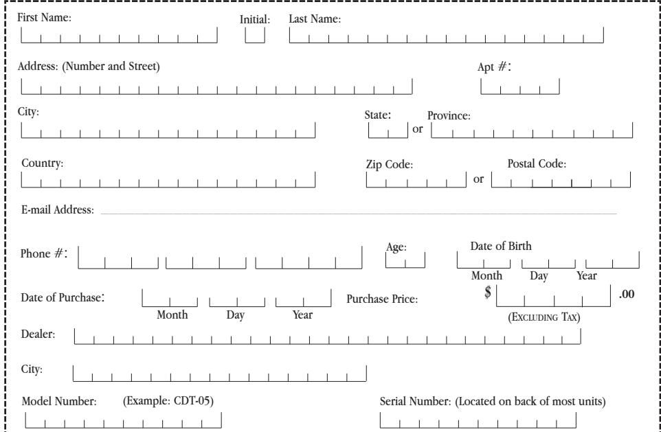
Save postage and register your product online at www.geminidj.com and automatically be registered for great prize giveaways!
If you do not have internet access, fill out the form below and mail to the appropriate address listed at the right side of this page.
Cut along this line & keep the rest of this page for your records.
-For your records

IN FRANCE
In the event that you need service on your Gemini product under warranty, simply write a letter describing the problem, along with your contact information. Make sure to enclose a copy of your receipt for proof of warranty information. A return number is not required. You will be responsible for shipping charges to Gemini UK, and Gemini UK will pay to return the unit to you if it is considered under warranty.
USA
GEMINI SOUND PRODUCTS
Worldwide Headquarters
120 Clover Place
Edison, NJ 08837 USA
Tel: (732) 738-9003
Fax: (732) 738-9006
FRANCE
GEMINI FRANCE (GSL)
1, Allee d'Effiat,
GEMINI SOUND PRODUCTS GMBH
Liebigstr. 16,
Haus B - 3. OG,
85757 Karlsfeld
Germany
Tel: 08131-39171-0
Fax: 08131-39171-8
UK
GEMINI SOUND PRODUCTS
Unit C4
Hazleton Industrial Estate, P08 9JU
Waterlooville, UK
Tel: 087 087 00880
Fax: 087 087 00990
SPAIN
GEMINI SOUND PRODUCTS S.A.
Rosello, 516,
08026 Barcelona, Spain
Tel: 3493-436 37 00
Fax: 3493-347-6961
IN SPAIN
- GROUNDING OR POLARIZATION:
- Face
- Rear
- CS-02 PROFESSIONAL 5-CHANNEL STEREO FX MIXER
- INTRODUCTION:
- FEATURES:
- CAUTIONS:
- DO NOT EXPOSE THIS UNIT TO RAIN OR MOISTURE.
- DO NOT USE ANY SPRAY CLEANER OR LUBRICANT ON ANY CONTROLS OR SWITCHES.
- CONNECTIONS / SETUP:
- REPLACING THE X-FADER AND CHANNEL FADERS:
- USER REPLACEABLE PARTS:
- CROSSEADER: RG45 OR RG-45PRO
- SPECIFICATIONS
- WEIGHTS AND DIMENSIONS:
- OPTIONAL ACCESSORIES:
- NOTES:
- A C H T U N G !
- BITTE UNBEDINGT VOR BENUTZUNG DES GERÄTS LESEN!
- CONNEXIONS / MISE EN PLACE:
- POIDS & DIMENSIONS:
- WARRANTY AND REPAIR:
- LIMITED WARRANTY
- RETURN/REPAIR
- Save postage and register your product online at www.geminidj.com and automatically be registered for great prize giveaways!
- -For your records
- IN FRANCE
- USA
- FRANCE
- UK
- SPAIN
- IN SPAIN
Brand : GEMINI
Model : CS-02
Category : Audio Mixer