
20 - Audio Equalizer DBX - Free user manual and instructions
Find the device manual for free 20 DBX in PDF.

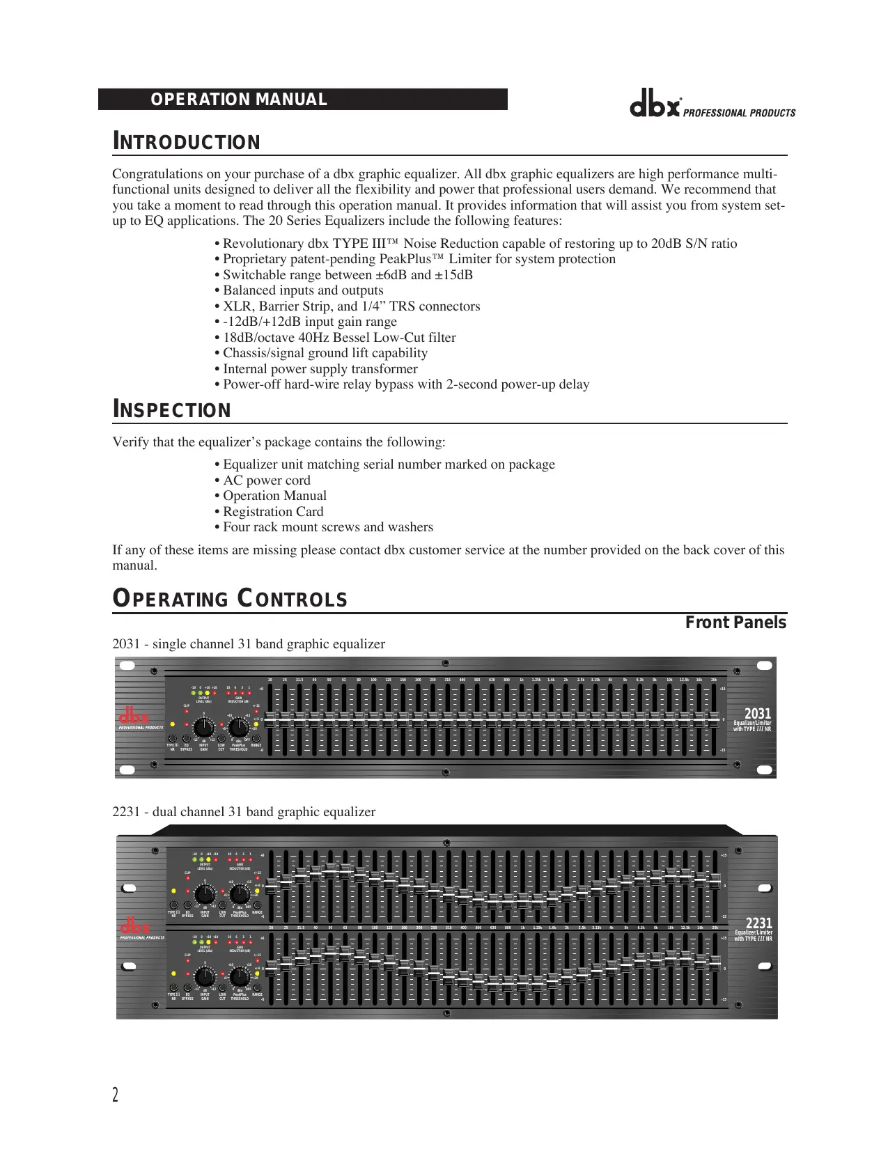


| Product type | Professional graphic equalizer (audio equalizer) |
| Available models | 2031 (mono 31-band), 2231 (dual 31-band), 2215 (dual 15-band) |
| Dimensions (approx.) | 483 x 44 x 200 mm (standard 1U rack) |
| Weight (approx.) | 4.5 kg |
| Power supply | 100-240 V AC, 50/60 Hz, internal transformer |
| Correction range | Selectable ±6 dB or ±15 dB per band |
| Number of bands | 31 bands (1/3 octave) or 15 bands (2/3 octave) depending on model |
| Inputs/Outputs | Balanced on XLR, 6.35 mm jack and terminal block |
| Input gain | Adjustable from -12 dB to +12 dB |
| Low-cut filter | 18 dB/octave at 40 Hz, Bessel type, switchable |
| Noise reduction | dbx Type III™ (up to 20 dB signal-to-noise ratio) |
| Limiter | PeakPlus™ with adjustable threshold from 0 dBu to OFF (+24 dBu) |
| Bypass | Switchable with red LED, 2-second delay relay |
| Output level meter | 4 LEDs indicating output level (clip at +18 dBu) |
| Gain reduction indicator | 4 LEDs for the PeakPlus™ limiter |
| LED indicators | Clip, Range (±6 dB yellow, ±15 dB red), Type III NR, EQ Bypass |
| Rack mounting | 19 inches, 1U, mounting screws included |
| Maintenance and cleaning | Use a soft, dry cloth. Do not use liquids or abrasive cleaners. |
| Safety | Do not open the device. Follow grounding instructions. Disconnect during storms. |
| Spare parts and repairability | Contact the authorized distributor. Replaceable fuse of the same type and rating. |
| General information | Professional equalizer for studio and sound reinforcement. Compliant with CE standards. |
Frequently Asked Questions - 20 DBX
User questions about 20 DBX
0 question about this device. Answer the ones you know or ask your own.
Ask a new question about this device
Download the instructions for your Audio Equalizer in PDF format for free! Find your manual 20 - DBX and take your electronic device back in hand. On this page are published all the documents necessary for the use of your device. 20 by DBX.
USER MANUAL 20 DBX
PROFESSIONAL PRODUCTS
OPERATION MANUAL
MODE D'EMPLOI
BEDIENUNGSANLEITUNG
MODE DE EMPLEO
IMPORTANT SAFETY INSTRUCTIONS

ATTENTION:
CAUTION
RISK OF ELECTRIC SHOCK DONOTOPEN

RISQUE DECHOCE ELECTRIQUE-NE PAS OUVRIR
WARNING: TO REDUCE THE RISK OF FIRE ELECTRIC SHOCK DON'T EXPOSE THIS EQUIPMENT T ORRAIN OR MOISTURE
The symbols shown above are internationally accepted symbols that warn of potential hazards with electrical products. The lightning flash with arrowpoint in an equilateral triangle means that there are dangerous voltages present within the unit. The exclamation point in an equilateral triangle indicates that it is necessary for the user to refer to the owner's manual.
These symbols warn that there are no user serviceable parts inside the unit. Do not open the unit. Do not attempt to service the unit yourself. Refer all servicing to qualified personnel. Opening the chassis for any reason will void the manufacturer's warranty. Do not get the unit wet. If liquid is spilled on the unit, shut it off immediately and take it to a dealer for service. Disconnect the unit during storms to prevent damage.
SAFETY INSTRUCTIONS
NOTICE FOR CUSTOMERS IF YOUR UNIT IS EQUIPPED WITH A POWER CORD.
WARNING: THIS APPLIANCE MUST BE EARTHED.
The cores in the mains lead are coloured in accordance with the following code:
GREEN and YELLOW - Earth
BLUE - Neutral
BROWN - Live
As colours of the cores in the mains lead of this appliance may not correspond with the coloured markings identifying the terminals in your plug, proceed as follows:
- The core which is coloured green and yellow must be connected to the terminal in the plug marked with the letter E, or with the earth symbol, or coloured green, or green and yellow.
- The core which is coloured blue must be connected to the terminal marked N or coloured black.
- The core which is coloured brown must be connected to the terminal marked L or coloured red.
This equipment may require the use of a different line cord, attachment plug, or both, depending on the available power source at installation. If the attachment plug needs to be changed, refer servicing to qualified service personnel who should refer to the table below. The green/yellow wire shall be connected directly to the units chassis.
| CONDUCTOR | WIRE COLOR | ||
| Normal | Alt | ||
| L | LIVE | BROWN | BLACK |
| N | NEUTRAL | BLUE | WHITE |
| E | EARTH GND | GREEN/YEL | GREEN |
WARNING: If the ground is defeated, certain fault conditions in the unit or in the system to which it is connected can result in full line voltage between chassis and earth ground. Severe injury or death can then result if the chassis and earth ground are touched simultaneously.
WARNING FOR YOUR PROTECTION READ THESE INSTRUCTIONS:
KEEP THESE INSTRUCTIONS
HEED ALL WARNING
FOLLOW ALL INSTRUCTIONS
DO NOT USE THIS APPARATUS NEAR WATER
CLEAN ONLY WITH A DRY CLOTH.
DO NOT BLOCK ANY OF THE VENTILATION OPENINGS. INSTALL IN ACCORDANCE WITH THE MANUFACTURER'S INSTRUCTIONS.
DO NOT INSTALL NEAR ANY HEAT SOURCES SUCH AS RADIATORS, HEAT REGISTERS, STOVES, OR OTHER APPARATUS (INCLUDING AMPLIFIERS) THAT PRODUCE HEAT.
ONLY USE ATTACHMENTS/ACCESSORIES SPECIFIED BY THE MANUFACTURER.
UNPLUG THIS APPARATUS DURING LIGHTNING STORMS OR WHEN UNUSED FOR LONG PERIODS OF TIME.
Do not defeat the safety purpose of the polarized or grounding-type plug. A polarized plug has two blades with one wider than the other. A grounding type plug has two blades and a third grounding prong. The wide blade or third prong are provided for your safety. If the provided plug does not fit your outlet, consult an electrician for replacement of the obsolete outlet.
Protect the power cord from being walked on or pinched particularly at plugs, convenience receptacles, and the point where they exit from the apparatus.
Use only with the cart stand, tripod bracket, or table specified by the manufacture, or sold with the apparatus. When a cart is used, use caution when moving the cart/apparatus combination to avoid injury from tip-over.

Refer all servicing to to qualified service personnel. Servicing is required when the apparatus has been damaged in any way, such as power-supply cord or plug is damaged, liquid has been spilled or objects have fallen into the apparatus, the apparatus has been exposed to rain or moisture, does not operate normally, or has been dropped.
POWER ON/OFF SWITCH: For products provided with a power switch, the power switch DOES NOT break the connection from the mains.
MAINS DISCONNECT: The plug shall remain readily operable. For rack-mount or installation where plug is not accessible, an all-pole mains switch with a contact separation of at least 3 mm in each pole shall be incorporated into the electrical installation of the rack or building.
FOR UNITS EQUIPPED WITH EXTERNALLY ACCESSIBLE FUSE RECEPTACLE: Replace fuse with same type and rating only.
MULIPLE-INPUT VOLTAGE: This equipment may require the use of a different line cord, attachment plug, or both, depending on the available power source at installation. Connect this equipment only to the power source indicated on the equipment rear panel. To reduce the risk of fire or electric shock, refer servicing to qualified service personnel or equivalent.
This Equipment is intended for rack mount use only.
IMPORTANT SAFETY INSTRUCTIONS
LITHIUM BATTERY
WARNING
CAUTION!
This product may contain a lithium battery. There is danger of explosion if the battery is incorrectly replaced. Replace only with an Eveready CR 2032 or equivalent. Make sure the battery is installed with the correct polarity. Discard used batteries according to manufacturer's instructions.
ADVARSEL!
This unit conforms to the Product Specifications noted on the Declaration of Conformity. Operation is subject to the following two conditions:
- this device may not cause harmful interference, and
- this device must accept any interference received, including interference that may cause undesired operation.
Operation of this unit within significant electromagnetic fields should be avoided.
- use only shielded interconnecting cables.
U.K. MAINS PLUG WARNING
A molded mains plug that has been cut off from the cord is unsafe. Discard the mains plug at a suitable disposal facility. NEVER UNDER ANY CIRCUMSTANCES SHOULD YOU INSERT A DAMAGED OR CUT MAINS PLUG INTO A 13 AMP POWER SOCKET. Do not use the mains plug without the fuse cover in place. Replacement fuse covers can be obtained from your local retailer. Replacement fuses are 13 amps and MUST be ASTA approved to BS1362.
DECLARATION OF CONFORMITY
Manufacturer's Name: Manufacturer's Address:
dbx Professional Products 8760 S. Sandy Parkway Sandy, Utah 84070, USA
declares that the product:
Product name:
dbx 2031, dbx2215 and dbx2231 Note: Product name may be suffixed by the letters-EU.
Product option:
None
conforms to the following Product Specifications:
Safety:
IEC 60065 (1998)
EMC:
EN 55013 (1990) EN 55020 (1991)
Supplementary Information:
The product herewith complies with the requirements of the Low Voltage Directive 73/23/EEC and the EMC Directive 89/336/EEC as amended by Directive 93/68/EEC.
Vice-President of Engineering 8760 S. Sandy Parkway
Sandy, Utah 84070, USA
Date: July 1, 2003
European Contact:
Your local dbx Sales and Service Office or
Harman Music Group
8760 South Sandy Parkway
Sandy, Utah
84070 USA
Ph: (801) 566-8800
Fax: (801) 568-7583
MANUAL CONTENTS
ENGLISH 2
FRANÇAIS 7
DEUTsCH 15
ESPAÑOL 23
ENGLISH CONTENTS
INTRODUCTION 2
INSPECTION 2
OPERATING CONTROLS 2
CONNECTING THE EQ TO YOUR SYSTEM 4
REAR PANEL DESCRIPTIONS 4
INSTALLATION CONSIDERATIONS 5
OPERATION AND APPLICATIONS NOTES 6
TECHNICAL SUPPORT / FACTORY SERVICE 6
SPECIFICATIONS 32
BLOCKDIAGRAM 33
INTRODUCTION
Congratulations on your purchase of a dbx graphic equalizer. All dbx graphic equalizers are high performance multifunctional units designed to deliver all the flexibility and power that professional users demand. We recommend that you take a moment to read through this operation manual. It provides information that will assist you from system setup to EQ applications. The 20 Series Equalizers include the following features:
- Revolutionary dbx TYPE III™ Noise Reduction capable of restoring up to 20dB S/N ratio
- Proprietary patent-pending PeakPlus™ Limiter for system protection
- Switchable range between ± 6dB and ± 15dB
Balanced inputs and outputs - XLR, Barrier Strip, and 1/4" TRS connectors
- 12dB/+12dB input gain range
18dB/octave 40Hz Bessel Low-Cut filter - Chassis/signal ground lift capability
- Internal power supply transformer
- Power-off hard-wire relay bypass with 2-second power-up delay
INSPECTION
Verify that the equalizer's package contains the following:
- Equalizer unit matching serial number marked on package
- AC power cord
Operation Manual - Registration Card
- Four rack mount screws and washers
If any of these items are missing please contact dbx customer service at the number provided on the back cover of this manual.
OPERATING CONTROLS
Front Panels
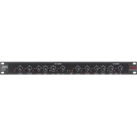
2031 - single channel 31 band graphic equalizer

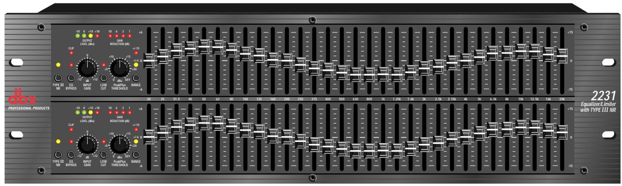
2231 - dual channel 31 band graphic equalizer
2215 - dual channel 15 band graphic equalizer

Input Gain Control: This control sets the signal level to the equalizer. It is capable of -12dB to +12dB of gain. Its effect is apparent by viewing the OUTPUT LEVEL BAR GRAPH.
EQ Bypass: This switch removes the graphic equalizer section from the signal path. (See Block diagram on Page 32.) The BYPASS switch does not, however, affect the INPUT GAIN, or LOW CUT filters.
EQ Bypass LED: This red LED lights when the EQ is in bypass mode. Note that bypass mode only effects the graphic equalizer section of the 20 Series EQs. The INPUT GAIN and and LOW CUT controls remain unaffected when the EQ is bypassed.
Boost/Cut Range Selection Switch and LEDs: This switch selects which of the two boost/cut ranges the equalizer will use, either ± 6dB or ± 15dB . The red LED lights when the ± 15dB range is selected, and the yellow LED lights when the ± 6dB range is selected. Note that the BOOST/CUT switch is slightly recessed. This is to prevent accidental activation of the switch, possibly causing damage to other sound system components.
Output Level Bar Graph: These four LEDs indicate output level of the equalizer. The red LED is 3dB below clipping and is marked as +18dBu . It monitors the level at the output of the equalizer after all other processing, including the limiter.
Clip LED: This LED lights whenever any internal signal level reaches 3dB below clipping which may occur when any of the following happen: 1) the input signal is "hotter" than +22dBu , 2) excessive gain is applied by the input gain control, or 3) excessive boost is applied using the frequency sliders.
Gain Reduction Meter: These four LEDs indicate the amount of gain reduction being induced by the setting of the PeakPlus™ LIMITER THRESHOLD control as the signal level from the graphic EQ section exceeds this limiter threshold setting.
PeakPlus™ Limiter Threshold Control: This control engages the PeakPlus™ limiter. It sets the threshold level at which :1 gain reduction will begin to occur. Its design is borrowed from the patent-pending PeakStopPlus™ Limiter found on the popular dbx 1066 and 1046 compressor/limiters. It is capable of a range of 0dBu through "OFF" (+24dBu). When the threshold control is set to "OFF", the limiter is effectively disabled, and no gain reduction will occur.
dbx Type III™ Noise Reduction Switch: The switch engages the dbx Type III™ Noise Reduction circuit within the EQ.
dbx Type III™ Noise Reduction LED: The yellow LED lights when the dbx Type III™ Noise Reduction circuit is activated via the NOISE REDUCTION Switch.
Frequency Band Slider Controls: Each one of these slider potentiometers will boost or cut at its noted frequency by ± 6dB or ± 15dB , depending upon the position of the BOOST/CUT RANGE switch. When all the sliders are in the center detented position the output of the equalizer is flat. The frequency band centers of the 2031 and the 2231 are marked at 1/3rd of an octave intervals on ISO standard spacings, while the frequency band centers of the 2215 are marked at 2/3rd s of an octave intervals on ISO standard spacings.
Low Cut Enable Switch: The LOW-CUT switch inserts or removes the 18dB/octave 40Hz Bessel low-cut filter from the signal path. When the LOW-CUT switch is pushed in, the LOW-CUT filter is IN the audio path.
CONNECTING THE EQ TO YOUR SYSTEM
The 20 Series Equalizers have balanced inputs and outputs that can be used with any balanced or unbalanced line-level device. For more specific information about cabling possibilities, please refer to the section entitled Installation Considerations, Page 5.
To connect the equalizer to your sound system refer to the following steps:
- Turn off all equipment before making connections.
- Mount equalizer in a standard-width rack.
Install the EQs in a rack with the rack screws provided. It can be mounted above or below anything that does not generate excessive heat. Ambient temperatures should not exceed 113^ (45^) when equipment is in use. Although the unit's chassis is shielded against radio frequency and electromagnetic interference, extremely high fields of RF and EMI should be avoided.
- Make audio connections via XLR, barrier strip, or 1/4" TRS jacks (according to application needs)
All three types of connectors for the inputs and outputs can be used for balanced or unbalanced connections.
The use of more than one connector at a time for the inputs could unbalance balanced lines, cause phase cancellation, short a conductor to ground, or cause damage to other equipment connected to the equalizer. More than one output may be used simultaneously as long as the combined parallel load is greater than 600
- Select the operating range with the BOOST/CUT RANGE SELECTION switch
Note: Be sure to reduce audio levels at the power amplifiers when changing the setting of this switch as it may generate an audible transient.
- Apply power to the equalizer
- Connect the AC power cord to the AC power receptacle on the back of the equalizer. Route the AC power cord to a convenient power outlet away from audio lines. The unit may be turned on and off from the rear panel power switch or a master equipment power switch. Since the 20 Series Equalizers consume a relatively small amount of power, the units may be left on continuously.
REAR PANEL DESCRIPTIONS
Rear Panels
2031 - single channel 31 band graphic equalizer
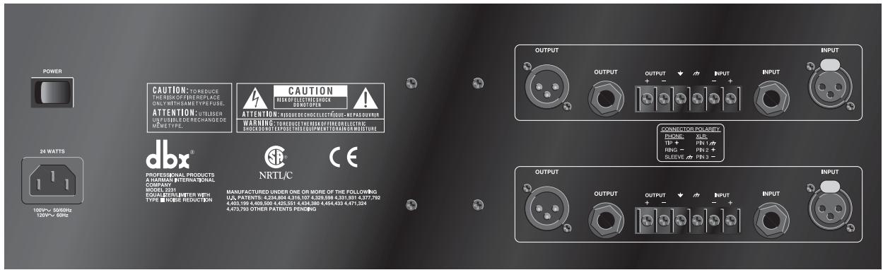
2231 - dual channel 31 band graphic equalizer
2215 - dual channel 15 band graphic equalizer
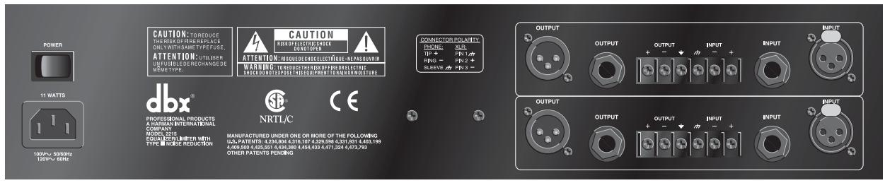
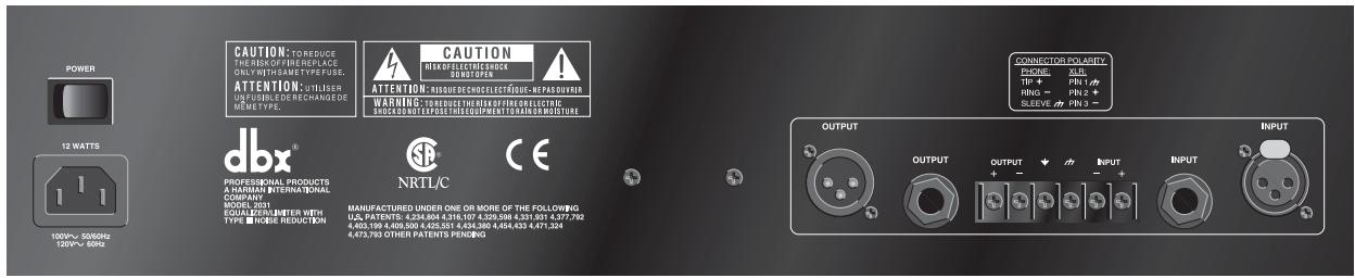
Power Cord Receptacle: Connects AC power to the equalizer.
Power Switch: Switches the power on and off. Always make audio connections with the power switch in the OFF position.
Input Connectors: Three types of input connectors are provided for input connections: female locking XLR type connectors, 1/4" tip-ring-sleeve phone jack connectors, and a barrier strip. The maximum input level that the equalizer can accept is +22dBu (ref: 0.775Vrms).
Output Connectors: Three types of output connectors are provided for output connections: male XLR type connectors, 1/4" tip-ring-sleeve phone jack connectors and a barrier strip.
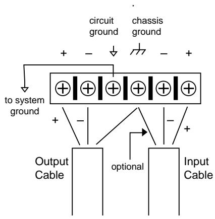
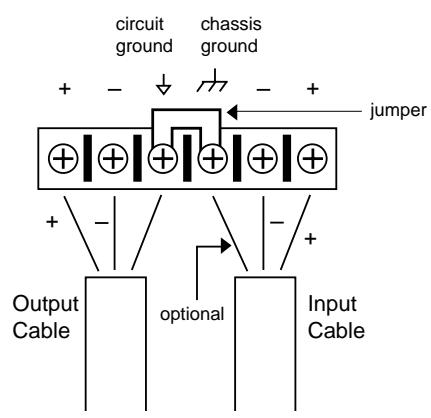
Chassis Ground Lift Strap: By removing the jumper connecting the two screws on the barrier strip, the chassis ground is separated from the circuit ground of the equalizer. This is sometimes necessary to prevent "ground loops" in a sound system. When lifting the ground strap, you must make a connection from the circuit ground (↓) terminal to some other ground point in your audio system in order for the equalizer to function properly.
Wiring Connections With Ground
INSTALLATION CONSIDERATIONS
Hookups and Cabling: The 20 Series Equalizers are designed for nominal +4dBu levels. The equalizers can be used with either balanced or unbalanced sources, and the outputs can be used with either balanced or unbalanced loads, provided the proper cabling is used.
A balanced line is defined as two-conductor shielded cable with the two center conductors carrying the same signal but of opposite polarity when referenced to ground. An unbalanced line is generally a single-conductor shielded cable with the center conductor carrying the signal and the shield at ground potential.
Input Cable Configurations: The equalizer has an input impedance of 40k balanced and 20k unbalanced. This makes the 20 Series Equalizers' audio inputs suitable for use with virtually any low source impedance (under 2k ).
Output Cable Configurations: The equalizer's output is capable of driving a 600 load to +18dBu. For maximum hum rejection with a balanced source, avoid common grounding at the equalizer's inputs and outputs. Most balanced (3-conductor) cables have the shield connected at both ends. This can result in ground loops which cause hum. If hum persists try disconnecting the shield on one or more of the cables in the system, preferably at the input of a device, not at the output.
OPERATION AND APPLICATION NOTES
The dbx 20 Series Graphic Equalizers are useful audio signal processing tools in situations where precise frequency control is required across the audible frequency spectrum.
When used with an audio spectrum analyzer the EQs can tune any acoustical environment -- from the studio to the concert hall -- to stop ringing, increase clarity, and flatten the overall frequency response of the environment. A real-time spectrum analyzer or other types of audio environment analyzers are very useful in determining the amount of equalization needed.
Insert the graphic equalizer between the signal source (usually a mixer) and the power amplifiers (or the crossover if there is one). Adjust the level and equalization as required to yield the desired system response. The long throw faders of the EQs allow very precise settings of the equalization for accurate equalization curves.
For optimum signal-to-noise response, the gain structure of the sound system must be properly set up. Each component of the sound system should be set at its nominal operating level, starting with the first element in the system, usually a mixing console. Each element should be run at its nominal operating level in order to take advantage of the maximum signal-to-noise properties of that element. Loudspeaker amplifiers, as the last element in the chain, should be set only as loud as necessary, in order to avoid inducing unnecessary noise into the system.
All active equalizers, by nature of design, add noise when boosting or cutting that can easily degrade the otherwise acceptable signal-to-noise ratio of a sound system. Drastic equalization can result in a loss of 20dB or more signal-to-noise. dbx Type III™ Noise Reduction was engineered specifically for applications such as this. It provides up to 20dB of noise reduction, thus restoring the dynamic range necessary for even the most demanding professional sound systems. The combination of proper wiring, proper gain structure and TYPE III™ Noise Reduction should render your sound system virtually noise free.
TECHNICAL SUPPORT / FACTORY SERVICE
The dbx 20 Series EQs are all solid-state products with components chosen for high performance and excellent reliability. Each unit has been tested and burned-in at the factory. No adjustment of any type should be required throughout the life of the unit.
If circumstances arise which necessitate repair, we recommend that your EQ be returned to the factory. This can only be done by receiving a RETURN AUTHORIZATION number from dbx customer service.
If you require technical support contact Customer Service. Be prepared to accurately describe the problem. Know the serial number of your unit (printed on a sticker attached to the chassis of the unit).
Contact information is printed on the back cover of this manual.
FRANÇAIS

ATTENTION:
CAUTION
RISK OF ELECTRIC SHOCK
DONOTOPEN

RISQUE DE CHOCE ELECTRIQUE-NE PAS OUVRIR
WARNING: TO REDUCE THE BISK OF FIRE ELECTRIC
SHOCK DONOT EXPOSE THIS EQUIPMENT TO RAIN OR MOISTURE
dbx Professional Products
8760 S. Sandy Parkway
Sandy, Utah 84070, USA
dbx Professional Products
President of dbx
8760 S. Sandy Parkway
Sandy, Utah 84070, USA
July 1, 2003
or Harman Music Group
8760 South Sandy Parkway Sandy, Utah 84070 USA
Ph: (801) 566-8800 Fax: (801) 568-7583
TABLE DES MATIERES
INTRODUCTION 10
VERIFICATION 10
RÉGLAGES 10
RACCORDEMENT DU CORRECTEUR A VOTRE SYSTEME 12
PANNEAU ARRIERE 12
CONSIDERATIONS SUR L'INSTALLATION 13
UTILISATION ET NOTES DE FONCTIONNEMENT 14
CHARACTERISTIQUES TECHNIQUES 31
SYNOPTIQUE 32
INTRODUCTION
dbx Professional Products
8760 S. Sandy Parkway
Sandy, Utah 84070, USA
IEC 60065 (1998)
EN 60065 (1993)
dbx Professional Products
Vice President of Engineering
8760 S. Sandy Parkway
Sandy, Utah 84070, USA
- July 2003
International Sales Office or Harman Music Group
8760 South Sandy Parkway Sandy, Utah 84070 USA
Ph: (801) 566-8800 Fax: (801) 568-7583
GARANTIEBEDINGUGEN
SHOCK DONOT EXPOSE THIS EQUIPMENT TO RAIN OR MOISTURE
dbx Professional Products
8760 S. Sandy Parkway
Sandy, Utah 84070, USA
dbx Professional Products
Vice President of Engineering
8760 S. Sandy Parkway
Sandy, Utah 84070, USA
July 1, 2003
International Sales Office or Harman Music Group
8760 South Sandy Parkway Sandy, Utah 84070 USA
Ph: (801) 566-8800 Fax:(801) 568-7583
CONTENIDO DEL MANUAL
| Bandwidth: | 20Hz to 20kHz, +0.5/-1dB |
| Frequency Response: | <10Hz to >50kHz, +0.5/-3dB |
| Noise Reduction In | (+/-6 and +/-15dB range): |
| Signal-to-Noise: | >100dB, unweighted, ref: +4dBu, 22kHz measurement bandwidth |
| Dynamic Range: | >118dB, unweighted |
| Noise Reduction Out: | (+/-6dB range): |
| Signal-to-Noise: | >94dB, unweighted, ref: +4dBu, 22kHz measurement bandwidth |
| Dynamic Range: | >112dB, unweighted |
| Noise Reduction Out: | (+/-15dB range): |
| Signal-to-Noise: | >90dB, unweighted, ref: +4dBu, 22kHz measurement bandwidth |
| Dynamic Range: | >108dB, unweighted |
| THD+Noise: | <0.04%, 0.02% typical at +4dBu, 1kHz |
| <0.5% at 1kHz with 15dB gain reduction | |
| Interchannel Crosstalk: | <-80dB, 20Hz to 20kHz (2215/2231) |
| Noise Reduction: | Up to 20dB of dynamic broadband noise reduction |
Function Switches / Touches de fonction / Funktionstasten / Selectores de unidades
| TYPE III NR: | Activates dbx Type III™ Noise Reduction Active la réduction de bruit dbx Type III™ Schaltet dbx Type III™ Rauschunterrückung ein und aus Activa la Reducción de Ruido dbx Type III™ | |
| EQ BYPASS: | Bypasses the graphic equalizer section in the signal path "Bypasse" la section correcteur graphique Schaltet den graphischen Equalizerteil aus dem Signalweg aus Hace una derivación de la sección de ecualizadorístico en el camino de la sealsil | |
| LOW CUT (recessed): | (enfoncé): | Activates the 40Hz 18dB/octave Bessel high-pass filter |
| (versenkt): | Active le filtré passée-haut 40Hz 18dB/octave de type Bessel | |
| (empotrado): | Schaltet das Bessel-Hochpassfilter (40Hz, 18dB/Oktave) ein und aus Activa el filtró para alto de Bessel de 40Hz, 18dB/octava | |
| RANGE (recessed): | (enfoncé): | Selects either +/- 6dB or +/- 15dB slider boost/cut range |
| (versenkt): | Sélectionne la plage d'atténuation/accentuation +/- 6dB ou +/- 15dB | |
| (empotrado): | Schaltet den Regelbereich der Schieberegler zwischen +/-6dB und +/-15dB um. Selección una de las dosGames refuerzo/corte de los deslizadores: +/-6dB ò +/-15dB | |
Indicators / Temoins / Anzeigen / Indicadores
| OUTPUT LEVEL: | 4-LED bar graph (Green, Green, Yellow, Red) at -10, 0, +10, and +18dBu VUmètre 4-Leds (verte, verte, jaune, rouge) à -10, 0, +10, et +18dBu 4-teilige LED-Zeile (grün - grün - gelb - rot) bei -10, 0. +10, +18dBu 4 LEDs (verde, verde, amarillo, rojo) a -10, 0, +10 y +18dBu |
| GAIN REDUCTION: | 4-LED bar graph (all Red) at 0, 3, 6, and 10dB VUmètre 4-Leds (toutes rouges) à 0, 3, 6, et 10dB 4-teilige LED-Zeile (4 x rot) bei 0, 3, 6, 10dB 4 LEDs rojos a 0, 3, 6 y 10dB |
| TYPE III NR: | 1 LED: yellow/jaune/gelb/amarillo |
| EQ BYPASS: | 1 LED: red/rouge/rot/rojo |
| CLIP: | 1 LED: red/rouge/rot/rojo |
| LOW CUT: | 1 LED: red/rouge/rot/rojo |
| +/-6dB: | 1 LED: yellow/jaune/gelb/amarillo |
| +/-15dB: | 1 LED: red/rouge/rot/rojo |
| Power Supply / Secteur / Netzteil / Alimentación de corriente | |
| Operating Voltage: | 100VAC 50/60Hz, 120VAC 60Hz; 230VAC 50/60Hz |
| Tension: | |
| Netzspannung: | |
| Tensión de regimen: | |
| Power Consumption: | 2031 15W; 2215 28W; 2231 28W |
| Consummation: | |
| Leistungsaufnahme: | |
| Consumo de energia: | |
| Mains Connection: | IEC receptacle |
| Connecteur secteur : | Prise chássis IEC |
| Netzanschluss: | IEC-Kaltgerätebuchse |
| Conexión de red: | tomacorriente IEC |
| Physical / Données physiques / Abmessungen und Gewicht / Dimensiones físicas | |
| Dimensions: | 2031/2215: 3.5" H X 19" W X 7.9" D (8.9cm x 48.3cm x 20.1cm) 2231: 5.25" H X 19" W X 7.9" D (13.4cm x 48.3cm x 20.1cm) |
| Dimensions (h x l x p): | |
| Abmessungen (H x B x T): | |
| Dimensiones (al x an x prf: | 2031/2215: 89 x 483 x 201 mm 2231: 134 x 483 x 201 mm |
| Weight: | 2031: 7.5 lbs. 2215: 8.5 lbs. 2231: 10.6 lbs. |
| Poids: | 2031: 3.4 kg |
| Nettogewicht: | 2215: 3.9 kg |
| Peso neto | 2231: 4.8 kg |
| Shipping Weight: | 2031: 8.5 lbs. 2215: 9.5 lbs. 2231: 11.6 lbs. |
| Poids à l'expédition: | 2031: 3,8 kg |
| Bruttogewicht: | 2215: 4,3 kg |
| Peso de embarque: | 2231: 5,3 kg |
Note: Specifications subject to change.
PROFESSIONAL PRODUCTS
8760 South Sandy Pkwy.
Sandy, Utah 84070
Phone: (801) 568-7660
Fax: (801) 568-7662
E-mail: customer@dbxpro.com
World Wide Web: www.dbxpro.com
H A Harman International Company

- IMPORTANT SAFETY INSTRUCTIONS
- CAUTION
- SAFETY INSTRUCTIONS
- WARNING FOR YOUR PROTECTION READ THESE INSTRUCTIONS:
- LITHIUM BATTERY
- WARNING
- CAUTION!
- ADVARSEL!
- U.K. MAINS PLUG WARNING
- DECLARATION OF CONFORMITY
- MANUAL CONTENTS
- ENGLISH CONTENTS
- INTRODUCTION
- INSPECTION
- OPERATING CONTROLS
- Front Panels
- CONNECTING THE EQ TO YOUR SYSTEM
- REAR PANEL DESCRIPTIONS
- Wiring Connections With Ground
- INSTALLATION CONSIDERATIONS
- OPERATION AND APPLICATION NOTES
- TECHNICAL SUPPORT / FACTORY SERVICE
- FRANÇAIS
- WARNING: TO REDUCE THE BISK OF FIRE ELECTRIC
- TABLE DES MATIERES
- GARANTIEBEDINGUGEN
- CONTENIDO DEL MANUAL
- Indicators / Temoins / Anzeigen / Indicadores
- PROFESSIONAL PRODUCTS
Brand : DBX
Model : 20
Category : Audio Equalizer