SV-122 - AV amplifier VINCENT - Free user manual and instructions
Find the device manual for free SV-122 VINCENT in PDF.

User questions about SV-122 VINCENT
0 question about this device. Answer the ones you know or ask your own.
Ask a new question about this device
Download the instructions for your AV amplifier in PDF format for free! Find your manual SV-122 - VINCENT and take your electronic device back in hand. On this page are published all the documents necessary for the use of your device. SV-122 by VINCENT.
USER MANUAL SV-122 VINCENT
Instructions for use
english

Digital RDS AV Surround Receiver
Ampli-Tuner 5.1 AV RDS
we thank you for the confidence you prove in purchasing our product. It will match your high demands towards sound and manufacturing quality.
Though it is understandable that you want to plug and play this product instantaneously, we encourage you to read this manual carefully before installation. It will help you in handling and operating this machine in your system and obtaining the best possible performance, even if it was installed by your dealer.
Please follow the security precautions, though some instructions may seem obvious.
In the appendix to this manual you will find a glossary explaining some established technical terms. If there are open questions your audio specialist dealer will help you. He also represents your contact person in case of needed warranty service or repairs after the warranty period and is interested to hear from your experiences with Vincent products.
We wish you plenty of joy with your / our product,
your Vincent-Team
Cher client,
Security precautions 36
User Information 37
Scope of delivery 38
Description of the device 38
Remote control 41
Installation 44
Speaker Settings 52
Operating the receiver 56
Tips 61
Troubleshooting 62
Glossary 63
Technical Specifications 65
english
Dolby Surround Prologic
Klirrfactor (20 Hz-20 kHz, 8Ω):
Dampfungsfaktor:
Signal Rauschabstand:
This product has been designed and manufactured under strict quality and safety standards to meet all effective international security regulations. However, you should consider the following security precautions to avoid unnecessary harms:

Do not remove cover (or back). No user-serviceable parts inside refer servicing to qualified service personnel.

Maintenance / Changes

All devices connected to the wall outlet power supply may be dangerous to the user when used improperly. Do not attempt to service this product yourself. There are no servicable parts inside. Refer servicing to qualified personal only. This product or parts of this product must not be changed or reconstructed as this will void the warranty, as is the case for changes at the serial number. This product should be operated only from a power source providing 230Volts/50Hz AC. The power outlet must be compatible to the safety plug. Use this audio component only indoors. After a failure that tripped the fuse contact your audio specialist dealer or a service technician to replace this part.
Mains supply cord / Power Connection
Always pull the plug and never at the cable when separating the power cord from the power line. Make sure the power cable is not being squeezed, bent unnaturally or cut by sharp edges. Do not touch the cable with wet hands. Use the provided power cable or other ones offered by Vincent.
Humidity/Heat and Vibrations
The contact with moisture, liquids, rain or steam is a danger for all electrically powered devices and their users. Dangerous high voltages are present inside the enclosure. To reduce the risk of fire or electric shock, exposition of the appliance to those should be avoided. If that happened accidentally, the appliance must be separated from the power outlet and checked by a service technician. Never allow objects of any kind or liquids to get inside this product, through openings, as they may touch dangerous voltage points or short-out parts which could result in a fire or electric shock. Do not use the appliance near
water. This product should be situated away from all heat sources such as radiators, heat registers, stoves or other products that produce heat. Do not expose it to direct sunlight for an extended period. Do not expose the device to heavy vibrations.

Switch off
Always switch off the appliance before connecting or separating cable connections to other devices or loudspeakers, connecting or separating the power supply connection, leaving the device unused for an extended period or cleaning of the surface. After switching off power amplifiers, integrated amplifiers or receivers wait for about 1 minute before changing cable connections.

Heat generation
All amplifiers generate heat. A minimum distance of 50~mm around the sides and top of the device is recommended to provide adequate ventilation. Do not use the appliance in a closed cabinet or book case.

Volume
The maximum bearable loudness mostly appears far beneath the maximum volume setting of the amplifier. So be careful with this setting to avoid damage to your hearing. To prevent unwanted high sound level always reduce the volume setting before changing to another input channel.

Cleaning
Unplug the power cord from the wall outlet before cleaning the surface of the appliance. Use a damp cloth. Do not use aerosol cleaners, solvents, thin
SECURITY PRECAUTIONS
ners, inflammable chemicals, polish or other products that leave stains.
Battery Cells

Please read about the handling of batteries in the chapter „Remote control".
USER INFORMATION
Placing the components of your audio system

The setup and way of placement of your audio system will affect its sound quality. Therefore, place the equipment only on top of an adequate and stable base. To achieve the maximum of the sound quality potential of your system we recommend to place your electronic audio equipment on Vincent Racks and to not pile up the components.
Electronic waste regulations

This device is covered by the European directive 2002/96/EC. This is displayed by the crossed-out wheeled bin symbol on the back side of the housing.
The meaning for you is:
All electric and electronic devices that are out of use must be disposed of separately from the household waste and can be deposited free of charge in designated local and communal collection facilities appointed by the government or the local authorities. In doing so you help prevent potential negative consequences for the environment and human health. It will motivate manufacturers to produce recyclable and longlife products. You can obtain further information at your city office, the waste disposal service or the shop where you purchased the product.
CE - sign and regulations

This appliance is in accordance with all valid EU regulations necessary for receiving the right to display the CE-Sign. It is in conformity with the requirements to electric and electronic devices (EMC regulations, safety regulations and guidelines for low voltage devices).
Copyrights
© November 2006, all rights reserved.
This document has been created by Andreas Boer. It is a product of the Sintron Vertriebs GmbH, 76473 Iffezheim, Germany and must not (in parts or complete) be copied or distributed without their permission in written form.
Vincent is a registered trademark owned by Sintron Vertriebs GmbH, 76473 Ilfezheim, Germany.
"Dolby", "Prologic", and the double-D symbol are trademarks of Dolby Laboratories, Inc.
Disclaimer

Vincent is permanently improving and developing its products. This means that designs, componentry or features are subject to changes without notice. Manufacturer and owner of the trademark have no obligation to announce technical changes to the appliance as far as dedicated to the technical progress.
All contents of this manual are of informational character and may be altered at any time without prior notice. No obligations or responsibilities for the owner of the trademark Vincent arise from these informations. He will not take responsibility for the correctness of the given information.
Explanation of the graphic symbols

The lightning flash is intended to alert you to the presence of uninsulated "dangerous voltage" within the product's enclosure that may be of sufficient magnitude to constitute a risk of electric shock to persons.

The exclamation point is intended to alert the user to important operating and maintenance (servicing) instructions in the literature accompanying the product.

This symbol marks useful hints and information.
SCOPE OF DELIVERY
Please check the contents of the package, it should contain the receiver SV-122 and the following:
1 remote control VRC-12
- 2 batteries of the type AAA (LR3)
1 power cable
1 AM loop antenna
1 FM antenna wire
- this handbook
DESCRIPTION OF THE DEVICE
Home theater systems are supposed to make original movies an authentical and sensational experience. A unit of purely Vincent AV components can master this challenge in excellence. Accurate electronics circuit design, up-to-date decoding technology, approved solid mechanical construction and large reserves in the electrical power circuit make the reproduction of explosive film scenes as well as quiet and sensitive passages as close to reality as possible. Additionally, benchmarks in cost-per
formance ratio are set.
The SV-122 is a compact, user friendly multi channel receiver with extraordinary dynamics and the renowned musicality of Vincent audio products. Never compromising in Stereo as well as in Multi Channel Mode. It is the ideal partner for speakers and DVD players made by Vincent.
The device offers:
- decoding technology for Dolby Prologic II, PCM-Stereo and the digital surround formats
- an RDS Tuner with 30 presets for each frequency band (AM or FM)
- a clearly arranged, high-contrast, dimmable display
- more than enough power for most speaker types: 5x60 Watts RMS at 4, active or passive subwoofer possible
- all functions remote controllable
- a multi function knob at the front panel for convenient control of most functions
- audio input connectors for up to 6 source audio devices (1x coaxial digital, 1x optical digital, 3x stereo analog high level, 1x 5.1 channel analog high level)
- video input connectors for up to 3 AV devices (3x Composite or 3x S-Video)
- one video output connector for S-Video and one for Composite Video
- one pre-amplifier output connector for the Stereo-Signal ("PRE") and one active subwoofer ("SW"), respectively
- one audio output connector (stereo) for a recording device ("REC")
All user settings are being made directly at the front panel without the need of navigating through complex on-screen menus.
FRONT VIEW:
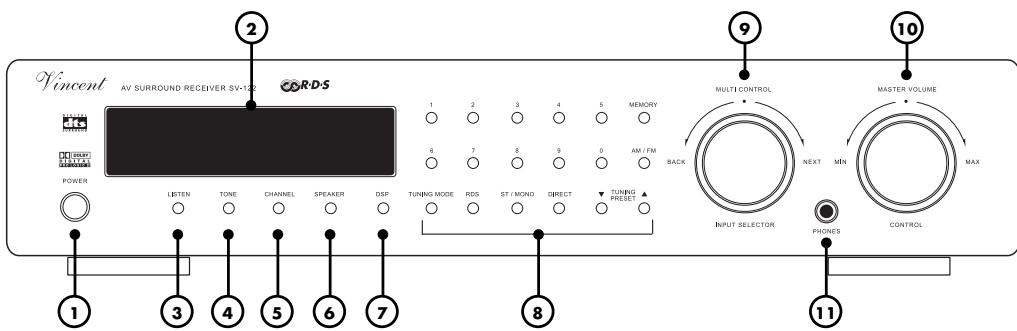
1. POWER: power switch,
turns on and off the main power of the receiver.
2. Display,
shows the selected input and operating status in normal operation. In setting mode the parameters of the specific settings are displayed.
In Tuner mode, radio station frequency or RDS data is visible.
3. LISTEN: selector for audio playback mode
This button allows manual selection of one of the audio playback modes such as „stereo".
4. TONE: sound adjustments,
Increase or decrease treble and bass of the system's sound. "MULTI CONTROL" (9) is used to change the values.
5. CHANNEL: equalization of speaker
channel volume levels With this button the receiver can switch to settings mode for adjusting volume level balance and making all speakers have the same volume level at your favourite position in the room. "MULTI CONTROL" (9) is used to browse all available settings. Settings can not be made if the input "5.1CH" has been selected.
6. SPEAKER: speaker configuration
Using this button you can enter an editing mode to give information about your speaker system to the sound management of the receiver. Settings can not be made if the input "5.1CH" has been selected. "MULTI CONTROL" (9) is used to change through all available settings.
7. DSP: programs for surround sound conditioning
Choose between eight digital methods of sound conditioning, for example simulation of the sound in a big concert hall. "MULTI CONTROL" (9) is used to browse all available settings.
DSP programs can not be used for the receiver input "5.1CH".
8. Tuner buttons
Number block and other buttons needed for operating the RDS-Tuner. See Chapter "Operating the receiver - Tuner".
9. MULTI CONTROL / INPUT SELECTOR: general purpose selection knob
In normal operation it is used to select another input channel. In settings mode (TONE, CHANNEL, SPEAKER, DSP and some tuner modes) this button can change the parameters of different settings.
10. MASTER VOLUME: volume level controller
Used to control the overall volume level of the system: speakers, headphones and the "PRE" (19), "SW" (18) outputs.
11. PHONES: 6,3 mm standard stereo jack, the socket that you can connect your stereo headphones to. Min. impedance: 32 ohms.
REAR VIEW:
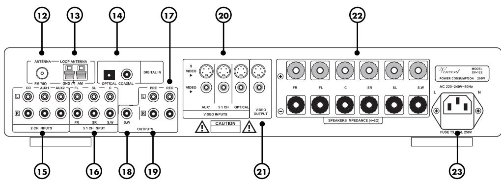
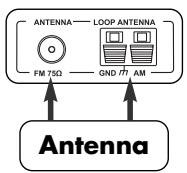
12. ANTENNA: FM connector 75Ω
Connect a standard coaxial antenna cable here. If there is no antenna wall outlet in the room, an indoor aerial or the supplied FM antenna wire can be utilized.
13. AM LOOP ANTENNA
Connect both cable ends of the loop antenna here if you want to listen to AM broadcast.
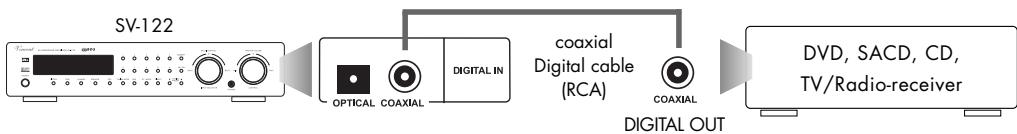
- DIGITAL IN: audio connectors for devices providing a digital audio signal, for example DVD-Players. "OPTICAL" is used for TOSLINK digital connection and "COAXIAL" for electrical connection using a coaxial cable.
15.2 CH INPUTS: terminal with connectors for audio signals of the source devices that provide analog stereo audio signal (for example CD-Players, video recorders). - 5.1 CH INPUT: connection terminal for the audio signal of a source device that provides analog multi channel audio signal (for example an SACD-Player or digital TV receiver)
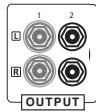
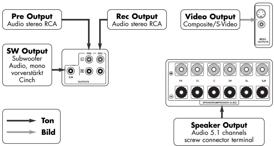
- OUTPUT „REC“: connectors dedicated to a stereo audio recording device (RCA) If desired, connect for example an audio recording device (CD-recorder, tape recorder etc.). The unchanged front audio signals (L,R) of the selected input source device are supplied here.
18. OUTPUT „SW“: pre-amplifier output signal for the subwoofer
Connect an active subwoofer here if you want to use one.
-
OUTPUT „PRE“: pre-amplifier output If desired, one additional stereo main amplifier or two mono main amplifiers can be connected here. The pre-amplified front audio signals (L,R) of the selected input source device are availa-ble at these connectors.
-
VIDEO INPUTS: input connectors for video signals of the source devices (for example a DVD-Player)
-
VIDEO OUTPUT: connection providing the video signal to the displaying device (for example TV, video beamer)
22. SPEAKERS: screw terminals
Output connectors for front, center and surround speakers as well as one passive subwoofer. 4mm banana plugs can be utilized at the speaker cable.
23. AC power connector and fuse holder
To establish the power supply, connect the plugs of the power cable to the device and to a 230V AC wall outlet. The small plastic housing beneath the plug opening holds the fuse. Refer to the security precautions.
REMOTE CONTROL
Point the diode side of the remote set to the front panel of the receiver, make sure there are no objects between the remote set and the device. Keep the distance between remote set and device
less than 7 meters. Do not point from an angle greater than 30 degrees from the middle axis. Change the batteries when the distance of reliable operation is shortening.
REMARKS ABOUT HANDLING OF THE REMOTE CONTROL
Usage of battery cells
Incorrect handling of the batteries can cause acid leakage or in extreme cases explosion. The cells must be inserted respecting the correct polarity as seen on the plan inside the battery housing. For longlife operation do not mix old batteries and new ones and use the same battery type (for example alkaline). Some battery cells are rechargeable, some are not. Refer to the details written on the cell surface. Remove batteries when not using the remote control for an extended period. Batteries must never be short-circuited, disassembled or exposed to heat! Used batteries are hazardous waste and must be disposed of according to local regulations. Do not put them into household waste.

Use micro AAA cells (LR3) only.
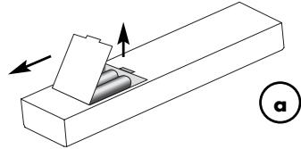
Replacing of the batteries:
a. Open and remove the plastic cover on the backside of the remote.
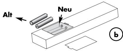
b. Remove used cells and insert new ones as seen on the scheme inside.
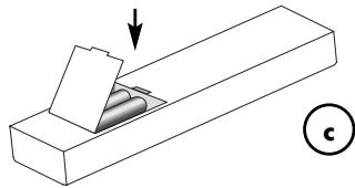
c. Close the cover.
BUTTONS REMOTE CONTROL
24. Buttons for input channel selection
These buttons choose the desired input source (device connected to CD, AUX1, AUX2, 5.1CH, OPTICAL, COAXIAL (14)(15)(16) or the built-in TUNER) that you want to change to.
- AM, FM If the receiver input "TUNER" has been chosen, this button switches between AM and FM mode. A suitable antenna must be connected to the corresponding antenna input (12)(13).
26. Number block for the control of the Tuner
Number pad (0-9) for direct frequency input or selection of presets in Tuner mode.
- ST/MONO If the receiver input "TUNER" has been chosen, you can switch between stereo and mono reception of radio stations. If a station's signal quality is low in stereo mode, a change to mono mode may result in better sound quality.
- DIRECT If the Tuner has been selected as input source, after pushing this button you can enter a known radio station frequency directly by using the number buttons (26).
- MEMORY If the receiver input "TUNER" has been chosen, this button is used to store a previously selected radio station frequency to one of the memory presets. The procedure is described in the chapter „Operating the receiver - Tuner".
- TU.MODE If the Tuner has been selected as input source, you can use this button to choose between three settings that determine what function the buttons TU / PR (32) will have: "MANUAL" (manuel frequency scan), "AUTO" (automatic frequency scan) oder "PRESENT" (search the tuner preset stations stored previously).
- A.MUTE If the receiver input "TUNER" has been chosen, a volume muting that will be applied in manual tuning mode can be activated or deactivated using this button. It removes the noise at frequencies between the stations.
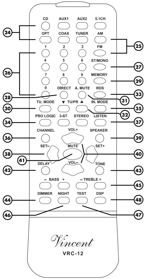
- TU / PR If the receiver input is set to "TUNER", you can select a radio station with these buttons. What function they will have is determined by the setting that has been done by pressing "TU.MODE" (30).
- RDS If the receiver input "TUNER" has been chosen, this button activates, deactivates and changes the different possible RDS services. RDS is available from some FM radio stations and provides the listener with text information seen in the front panel display (2).
-
PROLOGIC, 3-ST, STEREO These three audio playback modes (D. Prologic, 3-Stereo, Stereo), based on the stereo format, are also selectable using the "LISTEN" button [37] and can be directly chosen here.
-
IN.MODE Select the way the receiver will try to decode digital audio signals (e.g. DD, PCM) at the inputs "OPTICAL" and "COAXIAL" (14). Best choice is the setting "AUTO MODE".
See chapter "Operating the receiver - General functions". - CHANNEL In combination with the „SET“ buttons (38) this can modify the volume difference between the speaker channels (front left, center, etc.). For the front channels this is equivalent to the “Balance” setting of stereo systems.
See chapter "Speaker settings - Setting and testing the volume of the speaker channels". - LISTEN For every type of audio input signal (for example „Stereo analog“) there are several possible audio playback modes (for example „STEREO“, „3 CHANNEL STEREO“ or „PROLOGIC“). Using this button you can choose between them. The buttons (34) can be used to select those three playback modes directly. See chapter „Operating the receiver - Audio playback modes“.
- SET - buttons "SET+ and SET" have identical function as the knob MULTI CONTROL (9) at the front panel. In normal operation these but tons serve to switch to a different input channel. In settings mode (TONE, CHANNEL, SPEAKER, DSP and some tuner modes) they are used to browse available parameters.
- SPEAKER In combination with the "SET" buttons (38) this is used to set up the speaker configuration for optimizing the sound management system. See chapter "Speaker settings - Speaker configuration".
- VOL+ und VOL- Adjust with these buttons the volume level of speakers, phones and the signal of the preamplifier outputs „PRE" (19) and „SW" (18).
- MUTE, If this button is pressed, the volume of speakers, phones and the pre-amplified outputs "SW" (18) and "PRE" (19) is forced to zero. If pressed again, the original volume levels are being restored.
- DELAY After installing a speaker set, delay times for surround and center (Dolby Digital only)
channel signals must be adjusted, optimizing the sound of "Dolby Digital" and "Prologic" material. The "SET" buttons (38) are being utilized. Audio playback mode "Dolby Digital" or "Prologic" must be selected before settings can be made. See chapter "(3) Setting the delay times of the speaker channels ("DELAY" button)" for details.
- TONE Press this button repeatedly and use the "SET" buttons (38) to attenuate or increase bass and treble intensity of the sound. If no change in treble or bass intensity is wanted, the TONE function can be turned off without changing the values in one of the options. "Operating the receiver - General functions".
- DIMMER Press repeatedly to change the brightness of the front panel display in three steps.
- BASS / TREBLE Use these buttons to attenuate or increase bass and treble intensity of the sound. These settings can also be made using "TONE" (4)(43).
- NIGHT One touch on this button in "Dolby Digital" mode changes the sound to reduced dynamics (loud passages are made more quiet and quiet ones louder), also known as "midnight mode". Low-volume movie dialogues become comprehensible at low system volume levels while high-volume sound effects represent no disturbance to others any more.
- TEST Upon activation, a test noise sound changes through all speaker channels. It enables you to check the differences in volume levels of all speaker channels at your listening/viewing position in the room. One more touch of the button turns off the noise signal. See chapter "Speaker configuration - Setting the volume of the speaker channels".
- DSP Repeated use of this button changes through all eight possible sound conditioning formats and sound simulation modes like "Hall" or "Pop". See chapter "Operating the receiver - Digital simulating effects".
INSTALLATION
Home theater systems can reach different levels of complexity. Using this receiver, the system can consist in a minimal configuration of a DVD-Player, this receiver, one TV and a speaker set. If it is desired to use most of the potential of the AV receiver, it becomes harder to handle the system configuration with lots of components.
Imagine your AV system a general system that is provided with input signals (via its input connectors) and makes output signals available to components connected to its output connectors.
The receiver's function is to process the audio video signals from different sources (CD, DVD, TUNER) connected to the inputs and to supply them via its outputs to the components connected there.
It becomes clear that it is possible to guide the video signal directly to the displaying device and thus not feeding it through the receiver. This may be of use if you have connected only one video source device. In doing so you eliminate the (extremely small) loss in video quality that every unnecessary processing of signals creates. This solution is also useful if you want to use the coaxial digital audio connection from the AV-source, because this receiver input is audio-only. The advantage you have when feeding video signals through the receiver is its capability of switching audio and video signals of different inputs simultaneously.
Establish the necessary cable connections for all inputs first. Then add the outputs' cable connections. The last thing to do is to provide power by adding the power cable.

General instructions:
Note that there is no signal conversion between the two video signal formats S-Video and Composite. The displaying device will be able to display only the signals of video sources that use the same type of connection! It is always possible to connect video signals of AV sources that use a different type of video output directly to the displaying device (TV, video beamer).
Note that "COAXIAL" is an audio-only input. If you want to use it for an AV source as a DVD-Player, the video signal must be connected directly to the displaying device (TV, video beamer) as mentioned above. You can use all audio-only inputs (such as CD, AUX2") of the receiver for AV-sources that way.
Remove plastic protective covers
Prior to the first installation, remove the plastic protective covers on all used connectors.
Connections
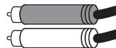
Most of the input, output, audio and video connectors are mechanically identical RCA jacks. Pay attention to connect the cables to the associated ones!
Connection quality
Make sure all connections are tight. Loose connections may cause noise, failure or malfunctions.


RCA Connection
Do not interchange connectors for right and left channel. At most audio equipment, RCA connec
tors are color-coded
using red for the right channel and white or black for the left channel.
Loudspeaker Connection
Use speaker cables with connectors (for example banana connectors) for safety.
Make sure that unprotected speaker cable ends can not touch each other or the metal of the receiver housing!
Connect only one speaker cable wire to one screw connector!
Mind the polarity of the speaker cable. Match it to the polarity of the screw terminals (positive = red = marked side of the cable). If one speaker has false connection polarity, sound quality reduces dramatically.
Use only speakers with a nominal impedance of not less than 4
Interconnection Cables
To achieve best performance only quality interconnection cables as produced by Vincent should be utilized. Prefer shielded audio cables. Consult your audio specialist dealer.
INPUT CONNECTIONS
| Name of input channel | Type of audio input and connector | Type of video input and connector |
| CD | stereo analog (RCA) | - |
| AUX 1 | stereo analog (RCA) | Composite (RCA) or S-Video (Mini-DIN) |
| AUX 2 | stereo analog (RCA) | |
| 5.1 CH INPUT | 5.1 analog (RCA) | Composite (RCA) or S-Video (Mini-DIN) |
| OPTICAL | 5.1 digital (Toslink) | Composite (RCA) or S-Video (Mini-DIN) |
| COAXIAL | 5.1 digital (RCA) | - |
| Antenna (Tuner) | Antenna 75Ω/loop antenna | - |
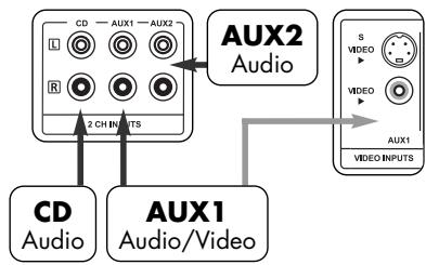
Audio inputs of "CD", "AUX1", "AUX2" and "5.1 CH" represent standard analog high level audio inputs using RCA jacks.
CONNECTING AUDIO/VIDEO SOURCES
To provide your audio system with the input signals (from DVD-Player, CD-Player, Tape etc.), connect their outputs and the antenna to the inputs of this receiver.
The table on previous page shows you properties and affiliation of the connectors. For information about connectors on your source devices refer to their manuals.

For utilization of a record player mostly a separate phono pre-amplifier is needed. It must be situated in the signal path between record player and one receiver stereo high level input. Most types are RCA-connected. Some models integrate this small amplifier unit and can be connected directly to the receiver. For more information see the manual of the record player.
First, connect all devices that can deliver multi channel audio. Inputs "COAXIAL", "OPTICAL" (14) and "5.1 CH" (16) can be used for those. Check the available connection standards at those devices to decide which receiver input to choose, respectively. Up to three multi channel sources can be connected to the receiver. If you should want to connect less than three multi channel sources, the free ones can be assigned to stereo sources. Should you decide to connect more than three multi channel sources, it is possible to establish a stereo connection to one of the receiver's free stereo input channels.
Second, connect all unassigned stereo source devices with free receiver stereo input channels. Again, the previous table can show you which receiver input channels can be used as AV inputs.
In the following you can see some typical setup situations:
CD-Player and other Stereo Audio-Sources
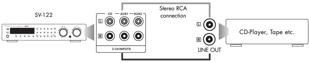
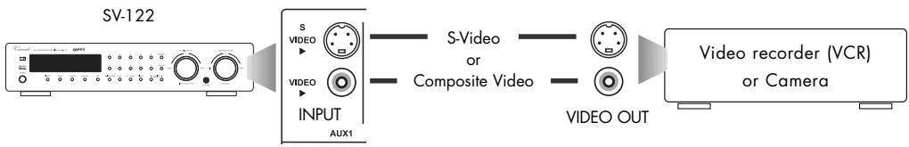
Stereo Audio-Source with Video connection
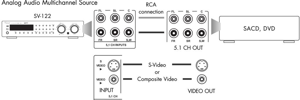
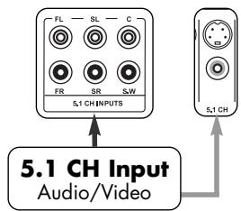
Analog Audio Multichannel Source
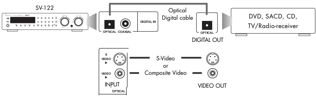
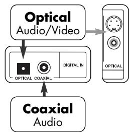
Digital Audio Source with optical signal connection
Digital Audio Source with coaxial signal connection
CONNECTING THE ANTENNA
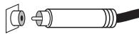
If a wall terminal that provides radio signal from satellite, house antenna or cable is available in the room, connect its radio socket with the "FM 75 jack (12). Otherwise you could use an indoor aerial or the provided lead-type FM antenna (wire). Fit the metal sleeve of the lead-type antenna over the core (center) pin of this connector.
If you want to receive AM broadcast, connect the loop antenna's wires to the AM antenna terminals "LOOP ANTENNA" (13) as shown.

OUTPUT CONNECTIONS
CONNECTING SPEAKERS AND THE SUBWOOFER
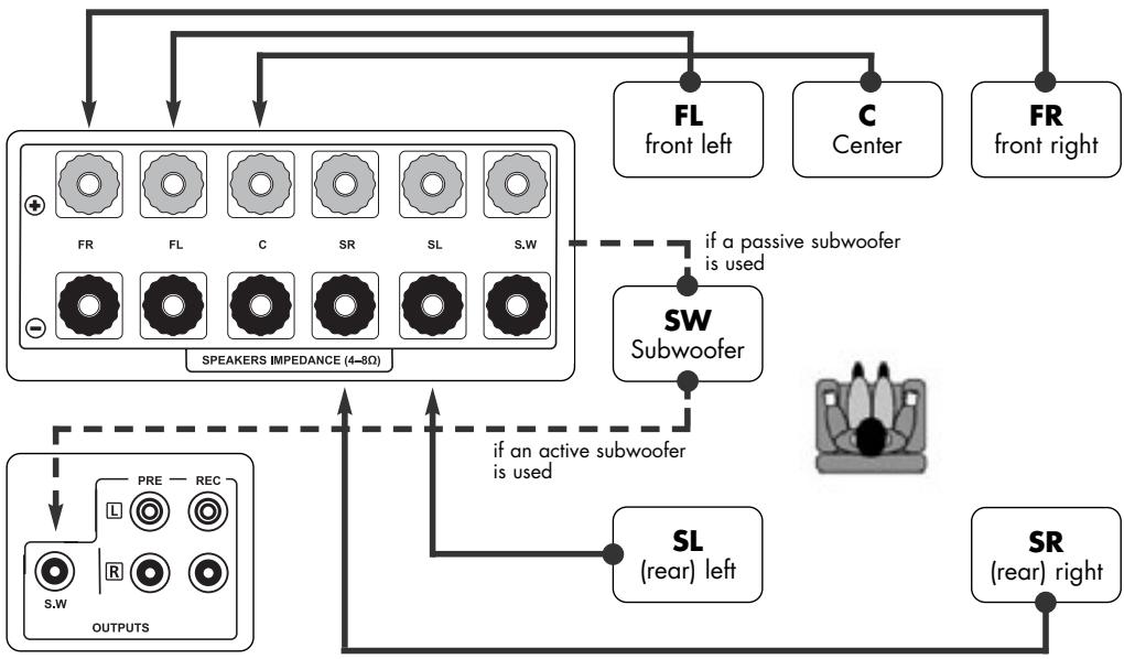
Two front speakers (right and left), one center speaker, two rear (surround) speakers and one passive or one active subwoofer can be used in the system based on this receiver. Every speaker is connected to its assigned pair of screw/banana connectors. If you are using an active subwoofer, it must be connected to the RCA output "SW" (18) instead.
CONNECTING SPEAKERS
Consider correct polarity, the positive contact is mostly marked red or with " + " . The side of the speaker cable that has to be connected with the positive socket has a marking.
If you use speaker cable equipped with connectors, all you need to do is connect the two plugs of each speaker's associated cable to the correct screw terminal jack.
Otherwise, remove a piece of approximately 1cm from the cable insulation at the cable ends, twist the blank cable ends and turn the speaker connector screw counterclockwise to release it. Insert the blank wire into the hole in the screw thread. Turn the screw connector clockwise to fasten the speaker cable.
Your receiver has two output connectors dedicated to the subwoofer signal: One speaker screw terminal in the "SPEAKERS" field for a passive subwoofer and one line level output for an active saubwoofer. An active subwoofer includes a built-in amplifier, a passive one not. You can recognize active subwoofer by their power supply cable or power supply connector at the rear panel. It is not necessary to connect a passive and an active subwoofer at the same time. An active subwoofer's RCA cable must be connected to the output "SW" (18) subwoofer jack (mono). When using a passive subwoofer, connect it to the associated speaker screw (banana) connectors "SW" (22) instead.
CONNECTION TO A RECORDING DEVICE
If that is desired you can connect an analog stereo recording device like a CD-Recorder or a tape recorder to the receiver's "REC" (17) RCA connectors. It delivers the unchanged, fixed stereo level (line level) of the source device that is connected to the SV-122 and currently selected. This output level is independent from the volume and mute settings.
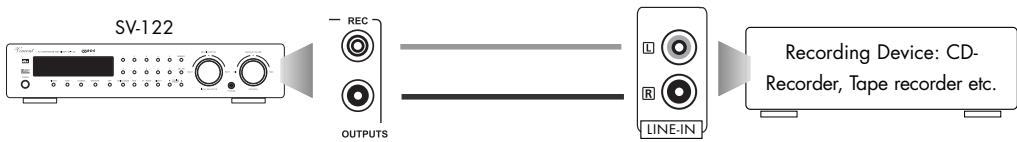
Connect this signal output of the preamplifier using RCA cables to the signal input (,RECORD^ or ,INPUT^ ) of the recording device. It is possible to connect other devices that accept the line level signal of the source that is selected at the receiver (for example integrated amplifiers).
AV recordings can be made if the receiver's video output is connected to the video input of the recording device instead of a displaying device.
STEREO PREAMPLIFIER OUTPUT "PRE"
These stereo RCA connectors (19) are only needed, if you want to add one or more main amplifiers for additional speakers.
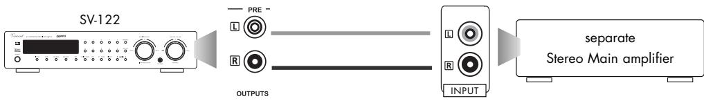
This could be of use if you want to listen to stereo music with higher-quality speakers and use a compact cinema surround speaker set for movies.
CONNECTING A DISPLAY (TV,VIDEO BEAMER,ETC.)
The receiver owns two video output connectors (21): one for Composite Video (RCA) and one for the S-Video (Mini-DIN) signal type. The last mentioned transmits separate color and brightness signals and thus has higher picture quality compared to Composite video.
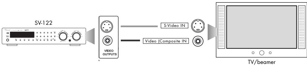
All display devices that accept one of those signal and connection types can be used with this receiver. The most used displays are TV and video beamers.
If the displaying device has additional video inputs, they can be used to accept the video signals of source devices that have audio connection with the SV-122 receiver.
CONNECTING HEADPHONES
A set of headphones equipped with a standard 6.3mm plug can be plugged into the "PHONES" jack (11) (stereo, analog) at the front panel. As long as a headphone is connected, the speakers and the preamplifier outputs "PRE" (19) and "SW" (18) of the system are muted. We recommend setting the
audio playback mode to "STEREO" when listening to headphones. Before the headphone connector is inserted or removed, the volume level should be reduced. All headphones can be used starting from an impedance by 32 ohms.
To establish the power supply push the plug of the power cable into the AC socket on the back panel and connect the plug on the other side of the cable to
a 220 V - 240 V AC 50 Hz wall outlet. Make sure that a current of 10 A can be provided
SPEAKER SETTINGS
Home cinema systems are designed for a variety of combinations with other consumer electronics and many different environments. That is why it is necessary to configure the system before first use and every time the speaker system is changed.
Usually, a quick setup procedure must be absolved, where audio/video settings have to be made. This setup has been reduced to the minimum required steps at this receiver, to kepp it user friendly. No video settings have to be taken on for this receiver. So only the speaker configuration and the required volume differences and delay times have to be defined. Note that some settings can only be made using the remote control.
It is best to follow the sequence displayed in the following table:
| Button(s) | Function | At front panel/with remote control | available parameters |
| 1 SPEAKER (6)(39) | Speaker configuration | both | SMALL LARGE NONE |
| 2 CHANNEL (5)(36) | Stereo bal. and vol. level difference of center, surround and subwoofer signals in relation to front channel volume level | both | Speaker channel volume differences in dB |
| TEST (47) | The speaker channel test sound ("TEST" (47)) can make volume level differences experienced at the listening position recognizable | remote control only | |
| 3 DELAY (42) | Delay times of the center and surround signals in relation to front channel signal | remote control only | Delay time in ms (milliseconds) |
1 SPEAKER CONFIGURATION ( „SPEAKER“ BUTTON)
These settings influence the distribution of the source signals to the different speaker channels. Since every surround sound system needs „bass management" to bring bass frequencies from specific or all channels to those speakers that are best adapted for the reproduction of those, it is necessary to give the receiver information about the kind of speakers used.
As „SMALL" speakers all speaker models without nameable bass (frequencies below 80Hz ) playback ability are declared, irrespective their size. „LARGE" speakers are all used speakers that have the ability to playback low bass frequencies. No speaker (.,NONE^ ) means that it is not used in the system. If, for example, no rear surround speakers have been installed, the required setting is „NONE".
At any time in normal operation you can enter the speaker configuration menu pressing „SPEAKER" (6)(39). Do this after first installation and every time you add, remove or exchange speakers.

If the „5.1 CH INPUT" is currently selected, it is not possible to change these settings.
If no button is pressed for some seconds, the normal operation mode (display of currently selected source input) is entered again. While settings mode is still active, the following settings can be made using "MULTI CONTROL" (9) or the "SET" buttons (38) on the remote control.
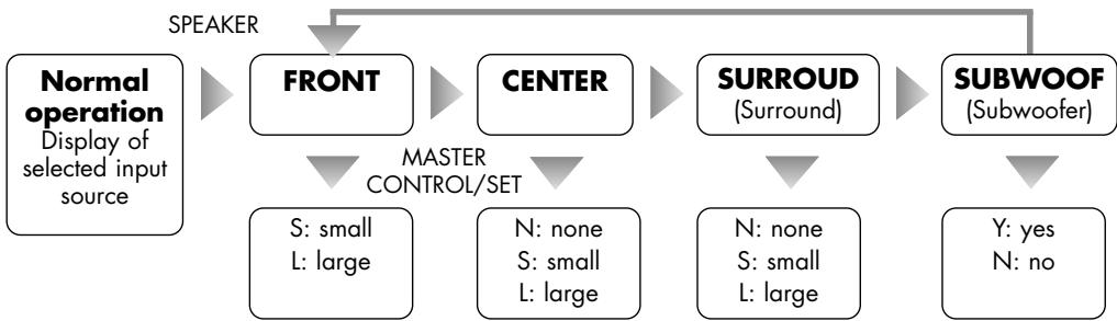
By using the button „SPEAKER" (6)(39) you select speaker categories, parameters can be changed using the knob „MULTI CONTROL" (9) or the remote „SET" buttons (38). The settings mode will be left automatically. Make your settings as described in the following:
| Front speaker | If the front speakers are able to transmit the complete audio frequency spectrum or if no subwoofer will be installed, choose “L”, otherwise choose “S”. |
| Center speaker | L (Large Center speaker) - S (small Center speaker) - N (no Center speaker) |
| Surround speakers | L (Large Surrounding speakers) - S (small Surrounding speakers) - N (no Surroundspeaker) |
| Subwoofer | Y (Subwoofer used) - N (no Subwoofer used) |

All Speaker settings are "global", they have effect on all source input channels except .5.1 CH INPUT and in all sound playback modes.
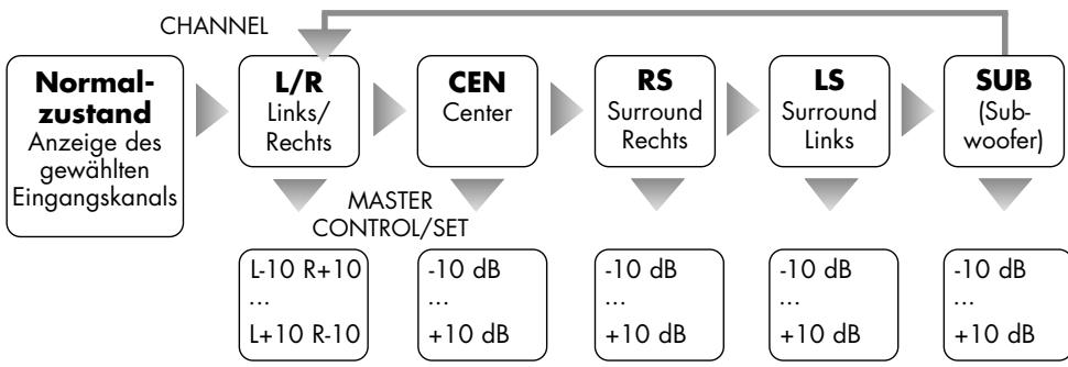
2 SETTINGS AND TESTING THE VOLUME OF THE SPEAKER CHANNELS (CHANNEL" AND ,TEST BUTTON)
In most cases the viewing/listening position must be chosen in a way that the distances to the different speakers are not equal. Additionally, efficiency of different speaker types varies, so that the experienced volume level at identical signal at the speaker output can be very different. This can reduce or undo the „surround“ effect of films. To avoid that, every speaker channel is separately adjustable in volume level.

If "5.1 CH INPUT" has been selected, these settings can not be changed.
If a source input channel with stereo audio format (CD, AUX1, AUX2, TUNER) has been selected, the volume level differences of the rear channels and the center channel (LS, RS und CEN) can not be changed.
Settings for speaker channels that are defined „NONE" or „N" in the „SPEAKER" (6)(39) menu can not be changed.
If a source input with digital audio ("OPTICAL" und "COAXIAL" (14)) has been selected, volume level differences of the rear channels and the center channel (LS, RS und CEN) can not be changed when a PCM stereo signal has been detected by the receiver or if one of the stereo-based sound playback modes ("STEREO", "3STEREO" and "PROLOGIC") has been selected.
Make sure the system volume level is at a low value. Activate the test sound using the "TEST" button (47) while staying at your favourite viewing/listening position in the room. A hissing noise can be heard changing through all used speaker channels that have not been deactivated in the "SPEAKER" (6)(39) settings menu. Check which speaker channel volumes, compared with the front left channel, have to be increased or decreased.
L C R SR SL SW
Press "TEST" (47) to deactivate the test sound. Press CHANNEL" (5)(36), repetitive use changes the settings display through all selectable speaker channels. Using the knob ,MULTI CONTROL" (9) at the front panel or the "SET" buttons (38) on the remote control, you can now eliminate differences in perceived volume levels. Levels can be attenuated or amplified up to 10dB. Settings mode will be left if no input is made for a few seconds. Check again, if all speaker channels have the same volume level at the listening position. The following scheme shows the menu options:

All settings are "global", they have effect on all source input channels except ".5.1 CH INPUT" and in all sound playback modes.
3 SETTINGS THE DELAY TIMES OF THE SPEAKER CHANNELS (DELAY" BUTTON)
In order to achieve a homogeneous sound field at your position in the room, it is necessary to adjust the delay time values for the rear speaker channels and the Center speaker channel. This is necessary, because in a speaker arrangement typical for a living room the front speaker distance to the listening position is usually larger than the rear speaker distance to the listeners. Irritations of the perception of direction by early surround signals are avoided by delaying the signal for the rear speakers. In some speaker arrangements a delay time must also be adjusted for the center speaker. As the result the sound signals of all speakers arrive at the listener at the same time. In the mode „PROLOGIC", additional 15ms (milliseconds) of delay cause the back channel sound to arrive later than the front channel sound. This is part of the "Dolby Surround Prologic" specification and reduces audibility of sound fractions crosstalk from the front channel signals and makes sure that the audio information, that is important for sensual location of acoustic sources, is first obtained from the front channels. This receiver allows Surround delay times from 0ms to 15ms (milliseconds) in the „Dolby Digital" mode and from 15ms to 30ms in the „Prologic" mode. Additionally, in the „Dolby Digital" mode, a Center delay time in the range 0ms...5ms must be set. All this has to be done after first installation of the system and to be repeated every time the speaker distances are changed.
Calculating the delay time values
Surround delay for Dolby Digital mode: Measure the distance from your listening position to the front left or right speaker. Substract from this value the distance from the listener's position to the rear speakers. Each 30cm of this difference should be related with a delay time of 1ms. Round to the closest multiple of 30cm . For example, a length difference of 120cm results in a required delay time of 4ms. The maximum value is 15ms.
Center delay for Dolby Digital mode: Measure the distance from your listening position to the Center speaker and to one of the front speakers. Subtract the Center distance from the Front speaker distance. Again, 30cm of this difference should be related with a delay time of 1ms. Round to the closest multiple of 30cm . If the Center speaker is about 50cm closer to the listener, 2ms of delay time should be applied. The maximum value is 5ms.
Surround delay for Dolby Prologic II mode: Add 15ms to the Surround delay time in Dolby Digital mode.
Setting the Dolby Digital delay times
Choose one of the receiver inputs with digital sound (OPTICAL, COAXIAL (14)). Use the button "LISTEN" (3)(37) to enter playback mode "Dolby Digital". Press the "DELAY" (42) button.
SDLY --ms Use the „SET" buttons (38) to change the parameter for the rear (surround) speaker channels to the calculated value for Dolby Digital. Press the „DELAY" (42) button again and enter the calculated value for the center channel delay using "SET" (38).
CDLY --ms If no input is given for a couple of seconds, the settings mode is quit into normal operation.
Setting the Dolby Prologic II delay time
Choose one of the receiver inputs except for „5.1 CH". Change the audio playback mode to „PROLOGIC" using the "LISTEN" (3)(37) button (do not use the button „PROLOGIC" on the remote control). Press „DELAY" (42).
SDLY --ms
Use the "SET" buttons (38) to change the parameter for the rear (surround) speaker channels to the calculated Dolby Prologic II value. If no input is given for a couple of seconds, the settings mode is quit into normal operation.

These changes can only be made while audio playback modes "PROLOGIC" or "DB DIG" (Dolby Digital) are selected.
Settings for Dolby Digital and Prologic are saved and stored separately.
If "5.1 CH INPUT" has been selected, these settings can not be changed.
| Action | Button(s) | Description |
| Switch on and off | POWER (1) | When switched off the device is internally separated from the AC power. It has no standby circuit, it is switched on and off at the front panel and not from the remote controller. Few seconds after switching on the receiver is operational. |
| Set the volume level | MASTER VOLUME (10)VOL+ (40)VOL- (40) | At the front panel: Turn the knob „MASTER VOLUME“ clockwise to increase the volume, and counterclockwise to decrease it.Using remote control: Keep the „VOL+“ button pressed to increase the volume.Use the „VOL-“ button to decrease it.In the process of changing volume the display changes to indicating the momentary numerical value of the setting. The volume minimum appears at -80 dB, the maximum volume setting is 00 dB. |
| Select the source input | INPUT SELECTOR (9)AUX1AUX2CD5.1 CH OPTICAL COAXIAL (24) | At the front panel: Turn the „MULTI CONTROL / INPUT SELECTOR“ until the desired input appears.Using remote control: Shortly press the corresponding touch button to change to the desired input channel (24)(for example „CD“ oder „AUX1“) or use the „SET“ buttons.The display now shows the name of the selected input channel.As a precaution, prior to changing the input channel the value of the volume setting should be reduced! |
| Mute the volume level | MUTE (41) | The mute function can be activated only from the remote control. It cuts off the receiver output signal and thereby silences loudspeakers, headphones and the outputs “PRE” (19) and “SW” (18) of the receiver. The next push on the button will recover the original volume. While the system is muted, the display (2) shows “MUTE”. |
| Aktion | Taste | Beschreibung |
| Change Tone settings | TONE(4)(43)SET (38)MULTICONTROL(9)BASS (45)TREBLE(45) | Attenuate or increase bass and treble intensity from „-10 dB" (maximum decrease) to the maximum value of „+10 dB" (maximum increase).If no change in treble or bass intensity is wanted, turn the TONE function off instead of keeping it unchanged by setting „00 dB" values. Front panel control: „MULTI CONTROL" changes the values or shuts the TONE function on/off. Repetitive use of the button „TONE" changes through the options.Remote control: „BASS+" and „BASS-" change bass intensity, „TREBLE+" and „TREBLE-" change the treble intensity. To activate or deactivate the TONE system, press „TONE" followed by „SET+" or „SET-". |
| Dim the display(brightness settings) | DIMMER(2) | Repetitive use of the „DIMMER" button changes the brightness of the frontpanel display. Three different grades of brightness can be chosen. This function can be used only from the remote control. |
| Choose the decoding mode for digital audio inputs | IN.MODE(35) | The digital audio inputs OPTICAL and COAXIAL (14) of the receiver can process different digital audio streams (PCM stereo, dts, Dolby Digital). Only if one of these inputs has been selected, the button „IN.MODE" located on the remote control allows to determine the mode the signal is decoded. It is recommended to keep the „AUTO MODE" setting.AUTO MODE automatic choice of decoding mode based on identified audio formatPCM MODE digital audio stream will be decoded as PCMDD MODE digital audio stream will be decoded as Dolby DITSDS MODE digital audio stream will be decoded as dtsThe setting is global and thus has effect for both digital audio inputs.Changing of this setting is not necessary and not possible for all analog audio inputs (CD, AUX1, AUX2, TUNER, 5.1 CH). |
| Reduce the sound's dynamics (Midnight mode, Compression) | NIGHT(46) | Dramatic movie sound requires dynamics, i.e. the ability to show large differences and fast changes in volume. To keep disturbances to other people in quiet environments to a minimum, many home cinema systems offer a function like „Night" . Quiet sounds are intensified, loud passages are dampened. That enables you to comprehend movie dialogues at low system volume levels while high-volume sound effects represent no disturbances to others.Activate this option by a short push on the „NIGHT" button, if repeated, the "night mode" will be deactivated.This function can be activated and deactivated only from the remote control and is only available in the audio playback mode "Dolby Digital". |
Audio playback modes ("LISTEN" button)
The SV-122 can accept different types of audio signals. Digital formats can be identified by the receiver and a suitable playback mode is changed to automatically if the input mode (IN_MODE) is set to "AUTO MODE". For all audio formats different playback modes are possible. At one time it could be preferred to listen to stereo sources using only front speakers and the subwoofer, at another time playback using the whole set of speakers may seem more attractive. The button "LISTEN" at the front panel (3) or on the remote control (37) as well as the buttons (34) serve to choose the audio playback mode.
Bear in mind that the subwoofer will always have a signal if it is activated in the „SPEAKER" menu.

If "5.1 CH INPUT" has been selected, these settings can not be changed. In this case, the receiver will output those signals that it receives at each channel's input connector.
If one of the stereo analog inputs (CD, AUX1, AUX2, TUNER) is selected, you can use the button "LISTEN" (3)(37) to enable the desired playback mode.
PROLOGIC STEREO 3-STEREO
If one of the digital inputs ("OPTICAL" or "COAXIAL" (14)) is selected, the following playback modes are optional by pressing the button "LISTEN" (3)(37):
(A) If the signal received is PCM Stereo, you can choose from the following:
PROLOGIC STEREO 3-STEREO
(B) If the input source receives a Dolby Digital signal, the following playback modes are available:
DOLBY DIGITAL STEREO
(C) If the input source receives a dts signal, the following playback modes are available:
DTS STEREO
The following table summarizes for every audio format which speaker channels are active and what conditions have to be met for them to be available.
| Tonformat | Display | Aktive Kanäle | Can be cho-sen when these input sources are selected | Can be cho-sen when these types of signals are received | |||
| Front (L+R) | Center- | Surround (SR+SL) | Subwoofer (SW) | ||||
| Stereo | STEREO | * | -- | -- | (*) | all except „5.1CH" | all |
| 3 Stereo (Stereo with Centerchannel) | 3 STEREO | * | (*) | -- | (*) | all except „5.1CH" | all except DolbyDigital + dts |
| Dolby Prologic II (analog multi channel format) | PROLOGIC | * | (*) | (*) | (*) | all except „5.1CH" | all except DolbyDigital + dts |
| Dolby Digital 5.1 | DB DIG | * | (*) | (*) | (*) | "OPT" and "COAX" | Dolby Digital |
| dts 5.1 | DTS | * | (*) | (*) | (*) | "OPT" and "COAX" | dts |
- Channel active, (*) Channel active if corresponding speaker has been made available in the „SPEAKER" menu, -- Channel inactive
TUNER
| Action | Button(s) | Description |
| Choose the RDS tuner as input source | INPUT SELECTOR (9) TUNER (24) SET (38) | To select the tuner push the „TUNER" button on the remote control or use the „INPUT SELECTOR" at the front panel. On the remote control, the "SET" buttons can also be used to change to the "TUNER" input. |
| Choose frequency band | AM/FM (8)(25) | Use these buttons, located at the front panel or on the remote control, to switch between AM and FM mode. FM offers better sound quality and a greater variety of radio stations. |
| Change between stereo and mono radio reception | ST/MONO (8)(27) | This button, located at the front panel or on the remote control, enables or disables the mono reception. This could be useful if a radio station's signal is weak. Then sometimes the sound quality is better in mono. |
| Choose a station by scanning the frequency band | TUNING MODE (8) TU_MODE (30) ▲TUNING PRESET▼ (8) ▲TU/PR▼ (32) | With the tuner selected as input, press the button "TUNING MODE" at the front panel or "TU_MODE" on the remote control to select of all three possible options one of the following two: • MANUAL stepping through the frequencies by steps of 50 kHz (FM) and 9 kHz (AM) In this mode, the buttons ▲TUNING PRESET▼ at the front panel and the buttons ▲TU/PR▼ on the remote control can be used to step manually through the frequency band. The display (2) shortly shows "TNR MANU". • AUTO automatic frequency scan In this mode, when the buttons ▲TUNING PRESET▼ at the front panel and the buttons ▲TU/PR▼ on the remote control are pressed, a frequency scan is started, it stops at the next frequency with a strong enough radio signal. The display (2) shortly shows "TNR AUTO". |
| Choose a station by entering the numerical frequency value | DIRECT (8)(28) Zahlentasten (8)(26) | Press the button "DIRECT" the receiver then waits for the input of a five digit number (on the number pad) that represents the frequency with two internal decimal places. If an invalid frequency is entered, "ERROR" appears in the display (2). |
| Choose a preset radio station | TUNING MODE (8)TU_MODE(30)▲TUNING PRESET▼ (8)▲TU/PR▼(32) | You can save up to 30 radio station presets that can later be selected by their number. If one or more presets have been saved, the corresponding radio station can be selected by typing the preset number on the number pad or by choosing the third possible "TUNING MODE" at the front panel or the button "TU_MODE" on the remote control):• PRESET ("TUNING/PRESET" buttons change through presets now)In this mode "TUNING/PRESET" buttons can be used to change through saved presets. The display (2) shortly shows "TNR PRST". |
| Save radio station presets | MEMORY(8)(29)Zahlentasten(8)(26) | To save a station's frequency to a preset, choose the station as described before, press the button "MEMORY" followed by the desired preset number (entered via the number pad, valid numbers are 1...30). For each of the frequency bands (AM and FM) 30 preset stations can be saved. |
| Mute volume during frequency scan | AMUTE(31) | In manual tuning mode ("TNR MANU") a volume muting can be activated or deactivated by using this button. It removes the annoying noise at frequencies between the stations, when the receiver has no or a weak radio signal. This option is only available from the remote control button. |
| Using the Radio Data System (RDS) | RDS(8)(33) | RDS (Radio Data System) permits the display of text information transmitted by many but not all FM radio stations.PS→PTY→TP→CT→RDS OFFA repeated push on the button „RDS" enables and disables this service and changes through four available types of information:PS station name A maximum 8 digits representation of the station's name is visible in the display, periodically changing back to the station's frequency.C clock display A clock showing the time of day is displayed, changing periodically to and from the display of the station's frequency. For example: „CLK 17:09".TP traffic program Some radio stations provide periodic traffic announcements. The display shows "TP ON", periodically changing back to the station's frequency if the station offers this service. If the station does not support it, "NO TP" is shown in the display.PTY programThe type of the station's program content is displayed (for example „CLASSIC", if mainly classic music is playing), periodically changing back to the station's frequency.RDS RDSThe station frequency is displayed.OFF deactivated |
DIGITAL SIMULATING EFFECTS
DSP is especially effective with material from CD, TV and FM radio. Just try different DSP-Modes when using the receiver to listen to a concert or watch a sports broadcast!
Repeated use of the „DSP" (7)(48) button changes the used DSP-mode:
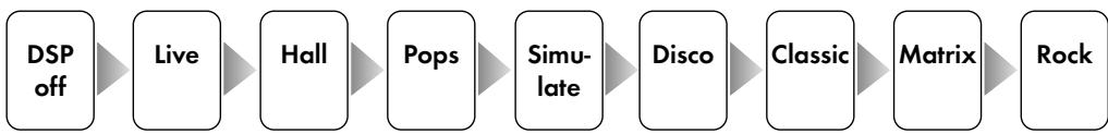
The simulation of different environments is created by adding reverberation and changing the frequency content of the sound signal without degrading the signal quality.
The DSP mode "LIVE" creates the atmosphere of a Live-Concert at the playback of different input sources.

If the receiver input "5.1 CH INPUT" is selected, DSP programmes can not be used.
TIPS
Burn in/ Warm up
Your audio components need a certain time period until they reach maximum performance. The duration of this "warm up" time is very different for the various elements of your audio system. Higher and homogeneous sound quality is achieved while keeping the device switched on.
Your audio specialist dealer has enough experience to give you more information.
Net frequency noise
Some audio source devices may together with the amplifier cause a humming noise at powerline frequency audible from your speakers. Usually its volume is variable with the volume setting of the amplifier. This is no sign of a defect or fault of your audio products but has to be eliminated.
Generally, every wall-powered device connected to the ground wire of the power plug can cause this problem when connected to the amplifier.
Mostly that this problem is caused by antenna-connected components (as TV-sets or Tuners), personal computers, electrostatic loudspeakers, subwoofer, record players or headphone amplifiers that are connected to the audio inputs of the amplifier. Another possible reason for humming noise is electromagnetic interference of other components' power supplies with pick-up-systems of record players (change the place of the record player for a test).
Some main amplifiers are equipped with a „Ground Lift“ switch. If it is activated, ground potential of the chassis and the protective ground wire are being separated from the central signal ground point. The protective ground wire keeps its function. Sometimes this helps prevent noise caused by errors in grounding.
If the problem occurs and cannot be solved by you-self your audio specialist dealer will help you.
TROUBLESHOOTING
| Symptom | Possible reason | Possible solution |
| No function after switching on | Power cable not connected to an active, qualified wall outlet. Power cable not connected tight to wall outlet or chassis jack or power cord damaged. Blown Fuse / receiver is damaged | Connect the power cable to an active wall outlet matching the needs of the receiver. Check the unplugged power cord and press the power plugs tight into wall outlet and the device's power connector. Contact your specialist dealer. |
| No playback, receiver display is functional | Volume setting too low. Not the desired input channel has been chosen. You did not (or not correctly) connect the output of the source device oder not to the desired input connector of the receiver. Source device does not give output signal. The volume has been muted. Speaker cable connections to the receiver are not correct or speaker cable damaged. | Carefully increase the volume. Revise your selection. Check and correct the connections. Start the playback of the source device. Deactivate the "Mute" function by pressing "MUTE" (41). Check and revise speaker cables and their connections. |
| One channel playback only | One of the speaker cables has not or not correctly been connected, or is damaged. One of the signal cables between the source and the receiver has not or not correctly been connected, or damaged signal cable. The balance setting ("CHANNEL") is extreme. | Check speaker cables and their connections on both sides. If necessary, replace speaker cable. Check signal cables and their connections on both sides. If necessary, replace signal cables. Correct this setting. |
| Remote commands have no effect | No batteries or used-up cells in the remote set. Line of sight between remote set and receiver device is blocked or maximum distance is exceeded or commands given from a too large angle. Device switched off. | Check and replace battery cells if necessary. Try and use remote set only at free line of sight inside the radius of 7 m facing the front panel. Power up the receiver. |
| Radio reception quality is low | Antenna has not been connected as required. AM loop antenna is not oriented correctly. | Check the connection of the antenna that must be affiliated to its connector. Note that there is one antenna input for each frequency mode, AM and FM (12)(13). Try different orientations and positions of the AM loop antenna. |
| No RDS | An AM station has been selected. Only some FM stations provide RDS. The FM station does not support RDS. The RDS Function has been switched off. | Do without this service or change to an FM station. Do without this service or change to a different FM station. Activate the RDS function using the “RDS” (8)(33) button. |
| Low frequency humming noise audible | See “Net frequency noise” in chapter “Tips” | |
GLOSSARY
RCA (Cinch)
Name of a coaxial two-pole plug-and-socket connection (abbrev. for "Radio Corporation of America", name of a US-American company). Plugs and sockets are built from a middle pin conductor and a concentric metal cylinder mantle as the outer conductor. One signal, audio or video, can be transferred. Compared to XLR, this type is being called "unsymmetrical signal connection" ("unbalanced").
Input sensitivity
Term used for the smallest input voltage that makes the amplifier generate the maximum output power at maximum volume setting. Examples: 100 to 500 mV (Millivolts) at high level inputs, 2 to 5 mV at Phono-MM-Inputs or 0,1 to 0,5 mV at Phono-MC-Inputs.
Audio sources / Audio source device
Components of your Hi-Fi system and devices that deliver the audio signal you want to listen to, for example CD-Players, Tuners, Tape recorders, DAT Recorders, Personal Computers, Record players, portable audio devices and many more.
Dolby
A company located in the Bay area near San Francisco (Dolby Laboratories, Inc), named after its founder and president Ray Dolby. In the recent
decades this company developed many technologies and signal processing standards for the improvement of audio playback and recording. Most famous products are „Dolby NR" (noise reduction for audio tape playback), „Dolby Surround Prologic" (analog multi channel audio standard) and „Dolby Digital" (digital multi channel audio standard).
Dolby Surround Prologic
Dolby Prologic is an analog four-channel audio system including two front channels, one center channel and one surround channel. The signals of both additional channels are integrated in a clever way into the Stereo signal (of VHS-Cassettes, LD's und DVD's, as well as diverse TV programmes), so that even conventional equipment, that cannot process surround sound, can use the integrated stereo sound as usual. A decoder separates the four channels. The Dolby Surround Prologic sound quality is not perfect: the surround channel ist monophonic and has a cut frequency range of 100 to 7000Hz . Moreover, as opposed to the digital surround systems a considerable crosstalk into both additional channels is present.
Dolby Prologic II (5.1)
From conventional two channel signals, for example digital PCM, analog Stereo or Dolby Surround Prologic signals 5.1 separate channels are calcula
GLOSSARY
ted. All Dolby Surround software offered up to now contains decoders for Prologic II. As opposed to Prologic the full HiFi frequency range is covered for all channels and there are two surround channels.
Dolby Digital 5.1 (AC-3)
Dolby Digital 5.1 (firstly named AC-3) is a digital audio multi channel format developed in 1992 for the movie sound recording and playback in the Dolby Laboratories. It contains up to six independent channels (two front channels, one center channel, two surround channels and one low-frequency channel (LFE)). The first mentioned five channels can transfer the full audible frequency range (20 to 20,000Hz ), the LFE channel only the low bass frequency range (20 bis 120Hz ). All separate digital signals are interleaved into one digital data stream
that can be transferred via ONE digital cable. Compression techniques are used to reduce the huge data rate necessary for this high quality signal data transfer by the factor of eight. The effective data rates are 384 and 448 kbit/s. Since 1997 Dolby Digital 5.1 is the standard DVD audio format.
DSP
stands for "Digital Signal Processor". This is a small microcomputer (IC, chip) designed for the processing of digital signals (audio or video). It can, for example, be used to add reverberation or echo to an audio signal. One of the most important factors in the perception of sound is reverberation, that is the way how the sound is reflected continuously by different objects and walls (similar to echoes) in the room.
TECHNICAL SPECIFICATIONS
Amplifier
Continuous channel output power at 8
Continuous channel output power at 4
Frequency response: (± 1dB)
Total Harmonic Distortion (20 Hz-20 kHz, 8Ω):
Damping factor:
Signal to Noise Ratio:
Input sensitivity:
Input overdrive / clipping:
Input impedance:
Channel separation:
Peak Current:
Amplifier Gain:
Recommended speaker impedance:
L/R/C/SL/SR channels 30 W, SW channel 60 W
L/R/C/SL/SR channels 50 W, SW channel 80 W
20 Hz - 20 kHz
< 0,1%
150
87dB
150 mV
1,3V
47 kΩ
60dB
10 A
43 dB
4Ω
FM Tuner
Tuning range:
Usable sensitivity:
Total Harmonic Distortion (1 kHz):
Frequency response:
Stereo Separation (1 kHz):
Signal to Noise Ratio:
Antenna Input:
87 MHz - 108 MHz (50 kHz steps)
5 dBμ mono
mono: 0.4% , stereo: 0.5%
30 Hz - 15 kHz, +1 dB/-1.5 dB
40 dB
mono: 72 dB, stereo: 70 dB
75ΩΩ
AM Tuner
Tuning range:
Usable sensitivity:
Total Harmonic Distortion (1 kHz):
Signal to Noise Ratio:
Antenna Input:
522 kHz -1611 kHz (9 kHz steps)
65 dBμ/m
0.8% at 80% mod.
50 dB at 80% mod.
loop antenna
Device
Power consumption
AC power connection type
Dimensions (WxHxL):
Weight:
Color:
210W
220 V - 240 V at 50 Hz AC
total 430× 95× 380mm height of feet 10mm
10 kg
black/silver
CONSIGNES DE SECURITE
Consignes/Modifications

Dolby Surround Prologic
L/R/C/SL/SR canaux 30 W, SW canal 60 W
L/R/C/SL/SR canaux 50 W, SW canal 80 W
20 Hz - 20 kHz
< 0,1%
150
87dB
150 mV
1,3V
47 kΩ
60dB
10 A
43 dB
4Ω
Tuner FM
Plage de réception:
Sensibilité:
30 Hz - 15 kHz, +1 dB / -1.5 dB
40 dB
mono: 72 dB, stéreo: 70 dB
75Ω
Tuner AM
Plage de réception:
Sensibilité:
Please keep the receipt, store it together with this manual. The receipt is your proof for the beginning of the warranty period. Note the serial number in the following box, you can read it from the rear side of the device.