STU-8 - Radio tuner VINCENT - Free user manual and instructions
Find the device manual for free STU-8 VINCENT in PDF.
| Product type | DAB+/FM Stereo Tuner |
| Brand | VINCENT |
| Model | STU-8 |
| Dimensions (W x H x D) | 430 x 133 x 359 mm |
| Weight (net) | 9 kg |
| Power supply | 230 V AC, 50 Hz |
| Power consumption | Not specified |
| FM frequency range | 87.5 – 108.0 MHz |
| DAB+ frequency range | Band III (174.928 – 239.200 MHz) and L-Band (1452.960 – 1490.624 MHz) |
| FM sensitivity | 0.8 µV |
| DAB+ sensitivity | 97 dBm (VHF), -96 dBm (L-Band) |
| Number of presets | 40 (20 FM + 20 DAB) |
| Audio outputs | RCA (unbalanced) and XLR (balanced) |
| Analog output level | 2 Vrms |
| Signal-to-noise ratio (FM) | 62 dB (Mono) |
| Signal-to-noise ratio (DAB+) | 100 dB |
| Total harmonic distortion (DAB+) | 0.01% (1 kHz) |
| Preamplifier technology | 12AX7 tube (hybrid tube/transistor) |
| Main functions | RDS, automatic/manual search, brightness control, remote control, power-on trigger |
| Maintenance and cleaning | Unplug before cleaning; use a soft, damp cloth; avoid abrasive products |
| Safety | Do not open (risk of electric shock); use only the supplied power cord; maintain 5 cm distance for ventilation |
| Spare parts and repairability | Repairs by qualified technician only; contact dealer |
| Supplied accessories | Power cord, RCA cables (2), remote control, AAA batteries (2), wire antenna, telescopic antenna, DAB adaptor, manual |
Frequently Asked Questions - STU-8 VINCENT
User questions about STU-8 VINCENT
0 question about this device. Answer the ones you know or ask your own.
Ask a new question about this device
Download the instructions for your Radio tuner in PDF format for free! Find your manual STU-8 - VINCENT and take your electronic device back in hand. On this page are published all the documents necessary for the use of your device. STU-8 by VINCENT.
USER MANUAL STU-8 VINCENT
Instructions for use
english

we thank you for the confidence you prove in purchasing our product. It will match your high demands towards sound and manufacturing quality. Though it is understandable that you want to plug and play this product instantaneously, we encourage you to read this manual carefully before installation.
It will help you in handling and operating this machine in your system and obtaining the best possible performance, even if it was installed by your dealer.
Please follow the security precautions, though some of those things may seem obvious.
In the appendix to this manual you will find a glossary explaining some established technical terms.
If there are open questions your audio specialist dealer will help you. He also represents your contact person in case of needed warranty service or repairs after the warranty period and is interested to hear from your experiences with Vincent products.
We wish you plenty of joy with your / our product,
your Vincent-Team
Cher client,
Safety guidelines 24
Other instructions 25
Included in delivery 26
Description of the appliance 26
Remote control 29
Installation 32
Operating the appliance 36
Tips 39
Search for errors 40
Technical specifications 42
Glossary 43
english
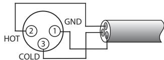
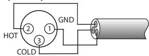
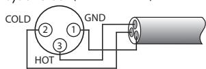
1.USA System (Pin 2 = COLD, Pin 3 = HOT)
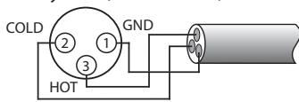
- Europäisches System (Pin 2 = HOT, Pin 3 = COLD)
Stereobstand 1 kHz (WIDE): 35 dB
THD+N: 0.01% (1 kHz)
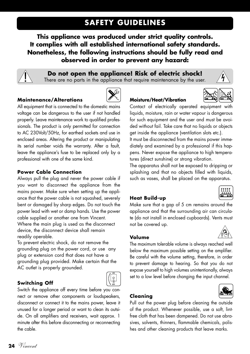
This appliance was produced under strict quality controls. It complies with all established international safety standards. Nonetheless, the following instructions should be fully read and observed in order to prevent any hazard:

Do not open the appliance! Risk of electric shock! There are no parts in the appliance that require maintenance by the user.

Maintenance/Alterations

All equipment that is connected to the domestic mains voltage can be dangerous to the user if not handled properly. Leave maintenance work to qualified professionals. The product is only permitted for connection to AC 230Volt/50Hz, for earthed sockets and use in enclosed areas. Altering the product or manipulating its serial number voids the warranty. After a fault, leave the appliance's fuse to be replaced only by a professional with one of the same kind.
Power Cable Connection
Always pull the plug and never the power cable if you want to disconnect the appliance from the mains power. Make sure when setting up the appliance that the power cable is not squashed, severely bent or damaged by sharp edges. Do not touch the power lead with wet or damp hands. Use the power cable supplied or another one from Vincent.
Where the main plug is used as the disconnect device, the disconnect device shall remain readily operable.
To prevent electric shock, do not remove the grounding plug on the power cord, or use any plug or extension cord that does not have a grounding plug provided. Make certain that the AC outlet is properly grounded.

Switching Off
Switch the appliance off every time before you connect or remove other components or loudspeakers, disconnect or connect it to the mains power, leave it unused for a longer period or want to clean its outside. On all amplifiers and receivers, wait approx. 1 minute after this before disconnecting or reconnecting the cable.
Moisture/Heat/Vibration

Contact of electrically operated equipment with liquids, moisture, rain or water vapour is dangerous for such equipment and the user and must be avoided without fail. Take care that no liquids or objects get inside the appliance (ventilation slots etc.).
It must be disconnected from the mains power immediately and examined by a professional if this happens. Never expose the appliance to high temperatures (direct sunshine) or strong vibration.
The apparatus shall not be exposed to dripping or splashing and that no objects filled with liquids, such as vases, shall be placed on the apparatus.

Heat Build-up
Make sure that a gap of 5cm remains around the appliance and that the surrounding air can circulate (do not install in enclosed cupboards). Vents must not be covered up.
Volume

The maximum tolerable volume is always reached well below the maximum possible setting on the amplifier. Be careful with the volume setting, therefore, in order to prevent damage to hearing. So that you do not expose yourself to high volumes unintentionally, always set to a low level before changing the input channel.

Cleaning
Pull out the power plug before cleaning the outside of the product. Whenever possible, use a soft, lint-free cloth that has been dampened. Do not use abrasives, solvents, thinners, flammable chemicals, polishes and other cleaning products that leave marks.
OTHER INSTRUCTIONS
Batteries

Take note of the instructions for using batteries in the chapter "Remote Control".
Setting up the appliance

How the system is set up has an effect on the sound quality. Therefore only place it on a suitable, stable surface. To make the most of your system's sound quality, we recommend placing the equipment on Vincent racks and not putting them on top of each other.
Old electronic equipment

This appliance is subject to the conditions set out in the European Directive 2002/96/EC. This is identified by the symbol of a crossed out waste bin on the appliance.
What this means for you as a consumer:
All old electrical and electronic equipment that is no longer used must be disposed of separately from domestic waste using places provided by the authorities. By doing so you can prevent damage to the environment and help to encourage manufacturers to produce more durable or reusable products. For further information about disposing your old appliance, please consult your local authority, waste disposal agency or the shop where you bought the product.
CE sign

This appliance complies with the current EU directives about attaining the CE mark and thus meets the requirements for electrical and electronic equipment (EMC regulations, regulations and regulations for low voltage equipment).
Declarations

This document was written by Andreas Boer. It is a product of Sintron Vertriebs GmbH, 76473 Iffezheim and may not be copied or distributed partly or in full without express, written consent.
Vincent is a registered trademark of Sintron Vertriebs GmbH, 76473 Iffezheim.
Vincent works continually to improve and develop its products. Therefore, the appearance and technical design of the appliance are subject to changes, as long as they are in the interest of progress.
The content of these instructions is for information purposes only. It can be changed at any time without prior notice and does not constitute any obligation on the part of the trademark's owner. The latter assumes no responsibility or liability for errors or inaccuracies, which may be included in these operating instructions.
Storage of the packaging
We strongly recommend that you keep the original packaging in case you need to transport the equipment again at a later date. Transport damages are mainly caused by improper packaging of the HiFi-devices. Because the original packaging fits the equipment accurately it will reduce the risk of damage if transport is necessary.
Explanation of the symbols

The lightening bolt tells you that dangerous voltages are present in the appliance, which can cause an electric shock.

This symbol brings your attention to particularly important information regarding operation and maintenance.

This symbol identifies useful information and advice about how to handle the appliance.
SCOPE OF DELIVERY
Please check the contents of the package, this should be in addition to Device, including the following accessories:
1 Network cable
- 2 RCA cable for connection to amplifier
- 1 remote control
2 AAA type batteries (LR3)
- 1 wire antenna
1 telescopic room antenna
1 DAB-Adapter for home antennas
This manual
DESCRIPTION OF EQUIPMENT
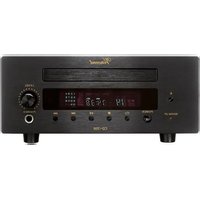
Although the development of digital sound formats towards multi-channel audio-video systems is continuous, high-quality stereo systems continue to enjoy great popularity. But one who wants to combine a first class equal toner with amplifiers, does not have much options nowadays. The STU-8 is a remote controlled DAB + / FMTuner program by Vincent. The pre-amplifier module is built on a 12AX7 tube and thus provides the silky sound and soothing warmth of the recorded music. This circuit was implemented as a variant of Vincent perfected hybrid technology, which benefits from transistor and tube amplification. Thus the reinforced tube plays the perfect field effect transistors (FET) of the output stage. Result of an extensive
development work and rigorous selection of components is a tuner, which brings out the most of the FM transmitter signals. Playing the dwindling number of radio stations, which sends signal high quality music without excessive compression, becomes a pleasure. Characteristics of the tuner are: Remote control, switchable RDS service, 40 (20 UKW/20 DAB) station memory and a dimmable / detachable display. Highest quality workmanship and of course excellent value for money. This tuner is the ideal partner for amplifiers, receivers, Pre-/Amp combinations, headphone amplifier and speakers from Vincent. Together with the HIFI furniture and speaker cables of the range, a perfectly harmonious system can be built.
FRONT VIEW
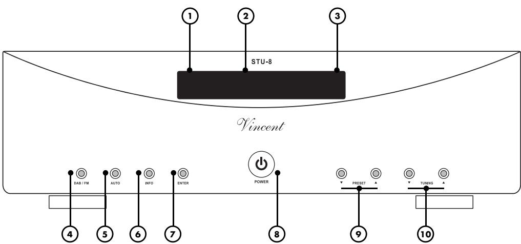
1. Warm up display
The display flashes, when the power is switched on- and after 30 seconds, the device is warmed up and operational.
2. Display window
3. Remote sensor field
This sensor receives infrared signals from the wireless remote control
4. DAB / FM
This button on the tuner switches between DAB and FM transmitters.
5. AUTO
Press this button to automatically tune in a station.
6. INFO
Press this key to display current channel information.
7. ENTER
Menu Enter key.
8. POWER
Turns the unit on or off. The device is in switched off and unplugged from the network.
9. PRESET /
The preset memory buttons. Press select, If the desired preset is displayed.
10. TUNING / (Down / Up)
To select a channel, press the button to scan the radio frequency.
REAR VIEW
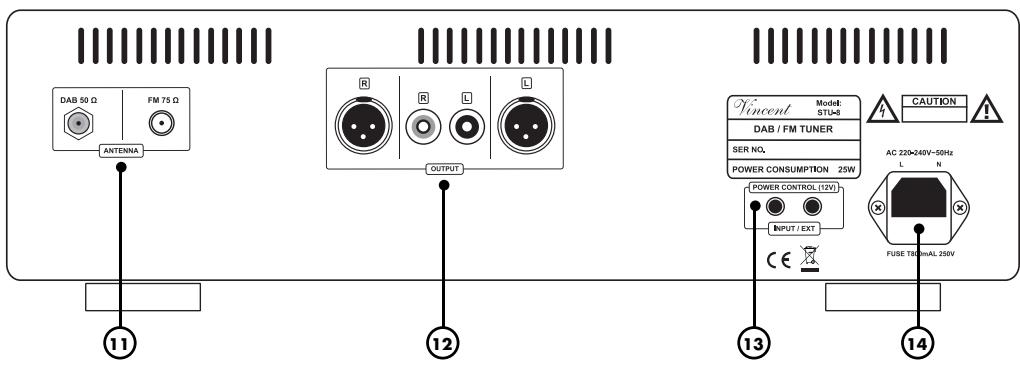
11. ANTENNA:
FM-antenna terminal
Connect a coaxial antenna cable for the FM reception of the radio part If no Antenna-wall connection exists, an Indoor antenna or the supplied wire for antenna can be used.
DAB-antenna terminal
Connect the supplied telescopic antenna at room.
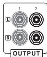
12. Analog output RCA / XLR jacks
These jacks can connect the amplifier with RCA / XLR jacks. Over Line-level connections, the STU-8 can be connected to an amplifier, preamplifier, etc.
13. POWER CONTROL (12V) OUTPUT
Over this jack (3.5mm) the power control signals (trigger) are produced.
14. 230V/AC-Power socket
Attach the power cable and connect it with the power supply
REMOTE CONTROL
Point the front of the remote control directly at the front of the appliance, making sure there are no objects between the remote control and the appliance.
The distance between the remote control and the appliance should not be more than 7m as the reliability of the remote control is affected beyond this range.
Make sure that you do not point the remote control at an angle to the appliance, as beyond an angle of ± 30^ to the centre axis the appliance may not respond as well to the remote control.
Change both batteries if the distance at which the remote control can be used effectively decreases.
BATTERIES
Using batteries
Handling batteries incorrectly can cause battery acid to escape or an explosion in extreme cases. The batteries must be correctly inserted taking note of the polarity, which is marked in the inside of the battery compartment.
In order to make full use of the batteries' life, do not mix new and used batteries. Make sure that you insert batteries of the same type.
Some batteries are rechargeable, others are not however. Take note of the precautions and instructions that are included on all batteries.
Remove the batteries if the remote control is not going to be used for a long time.
Under no circumstances must batteries be short-circuited, taken apart or heated up.
For environmental reasons, used batteries should be disposed of in accordance with local environmental regulations and not put with domestic waste.

Only use AAA (LR3) size batteries.
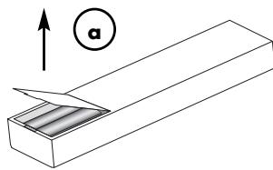
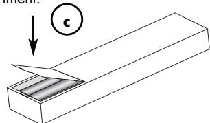
Changing/Inserting batteries:
a) Open and remove the battery compartment lid of the remote control by tugging sharply on the fishplate on the edge of the remote control. The battery compartment lid is held in place magnetically, there is no need to loosen the screws!
b) If necessary, remove used batteries and insert new ones correctly as shown by the diagram in the battery compartment.
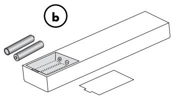
c) Put the compartment cover back on and close the battery compartment.
BUTTONS OF THE REMOTE CONTROL
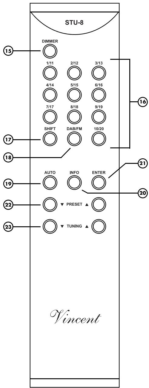
BUTTONS OF THE REMOTE CONTROL
15. DIMMER key:
Press this button to adjust the brightness, the light is brightest when the device turned on. Each time you press the button the lighting is dimmed up for the fourth time after it returns to the original brigh ness.
16. Preset channel buttons(1~10)
With these keys, the stations can be called and displayed. With the SHIFT key together 40 preset channels cab be used (FM 20, DAB 20).
17. SHIFT key
With this key the memory sections can be called, FM1 (1 ~ 10), FM2 (11 ~ 20), DB1 (1 ~ 10), DB2 (11~20).
18. DAB / FM-key
With this button you can switch between DAB and FM reception.
19. AUTO key - automatic station search
FM: By pressing this key, the device searches for the next air frequency.
DAB: Automatic Search for air channels
20. INFO key
Display for "Radio-Info Text" (RDS).
21. ENTER key
Choose between stereo and mono operation.
22. PRESET key
Switch between saved stations.
23. TUNING key
Manual Frequency search
INSTALLATION
Set up the cable links in a sequence as follows. Connect the power cable between device and power supply only after all other connections have been made.

DURING INSTALLATION PLEASE OBSERVE THE FOLLOWING ADVICE:

Protective caps
Prior to the first installation the protective plastic caps must be removed from all the connections used at the rear of the unit.
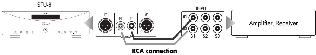
RCA connections
Mechanically identical RCA
plugs are available for analogue and digital outputs. Make sure that you do not get these connections confused during installation!
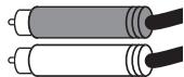
Make sure that you do not mix up the analogue connectors for right and left. The RCA plugs for these are mostly colour coded as follows: red for the right channel, black or white for the left channel.
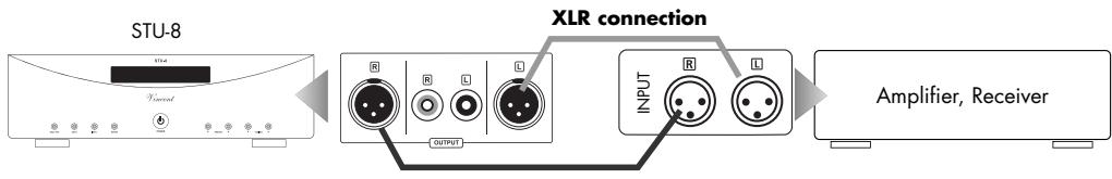
XLR connections
Note that European and US XLR signal use is different. This Vincent device uses the European system in accordance with Standard AES14-1992 of the Audio Engineering Society. The structure of the cable is in any event the same. Provided both connected devices meet the same standard, the signal connection is correct. This is always the case if both were manufactured by Vincent. If two devices with different standards are connected, the signal will then be inverted. In this case the signal use on one side of the connection must be changed. Your specialist dealer will assist you with this.
1.US System (Pin 2 = COLD, Pin 3 = HOT)
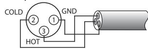
- European System (Pin 2 = HOT, Pin 3 = COLD)
Cable connections
Make sure that all plugs fit tightly. Inadequate connections can cause noise interference, failures and malfunctions.

To make the most of the components' sound potential, only high quality loudspeakers and connecting cables, for example Vincent cables, should be used. Your local stockist will be glad to advise you about this.
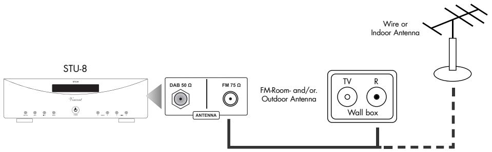
CONNECTING THE ANTENNA
If a wall socket for the FM antenna connection of satellite channels, cable channels or roof antenna is available then connect the radio connection to the input jack "FM 75Ω (11) on the device. For this, use a 75Ω coaxial cable. If such a junction is not present, the supplied wire antenna or a commercially available indoor antenna can be connected.
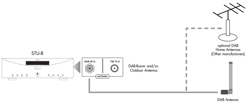
The supplied telescopic antenna room for moderate to strong signals should be sufficient for good reception. The antenna is plugged into the COAX 50 Ω (11) tri-band antenna F connector on the back of the device and should be secured by tightening the nut. The antenna should be aligned vertically, as DAB signals are vertically polarized.
In case of bad or no reception, there is a greater possibility to use antennas of other manufactureres.
CONNECTION TO AMPLIFIER, RECEIVER OR PREAMPLIFIER
Use of the analog output on RCA connector
Connect the RCA output sockets "OUTPUT" (13) with the sockets of the high level input of the preamplifier, integrated amplifier, receiver or another suitable device (headphone amplifier, recording input of a tape recorder etc.). In most cases the input is labelled "TUNER," "LINE IN" or "INPUT FRONT R/L". More information you will find in the user manual of this device.
Use of the analog output on XLR connector
Connect the sockets' OUTPUT "(12) with the high level input of an amplifier, preamplifier, receiver or any other suitable for high-level source device (headphone amplifier, receiving input of a tape recorder, mixing console, etc.). Usually such an input port is engraved with "LINE IN" or "TUNER". Information about the connectivity of the device with which the player should be connected can be found in the manual.
Check that the electricity supply to your home is appropriate to the device. The required voltage and frequency can be read on the back of the device beside the socket for the mains. If the electricity supply is appropriate, push the inlet connector of the supplied mains cable firmly into socket for the mains on the back of the device (14). Connect the other end of the mains cable to a mains socket.
CONNECTIONS FOR THE STANDBY CONTROL (POWER CONTROL)
Many AV systems or stereo audio systems consist of a multitude of individual components. To avoid the necessity of switching them on and off before and after every use, many manufacturers have equipped their devices with what is known as "POWER CONTROL" circuit or "TRIGGER". This kind of remote-controlled standby circuit is used primarily for preamplifier and power amplifiers. To employ these functions, direct or indirect cable connections must be made between the preamplifier (or integrated amplifier) and all the devices which support this function. The "POWER CONTROL" function operates in such a way that each switching on or off of one device in the system (usually the preamplifier) automatically brings about the switching on or off of all the connected devices which support this function. Please keep in mind that all devices which respond to the power control are not disconnected from the mains network when switched off. They are set to a standby state instead. For connecting cables, two-core cables with 3.5mm jack plugs (mono) are used. For each connection between two devices one of those cables is needed.
The STU-8 has two output connections for the power control. He can switch the signal for other components of a stereo system and produce output. Two devices that are to receive the switch signal may be directly connected to the two "POWER CONTROL" outputs (13).
However, if there are more than two devices, which can be controlled is connected, so it is necessary to control connection between the preamplifier and further to lead to control devices using the outputs of the two directly connected devices. To this end, in most devices of one of the two "POWER CONTROL" connections as signal input and the others are used as signal output. This way, supplies can be theoretically infinite in number of devices with the switching pulses. This method, the signal through the inputs and outputs of the devices and loop through to daisy-chain, is commonly known as "daisy chaining".
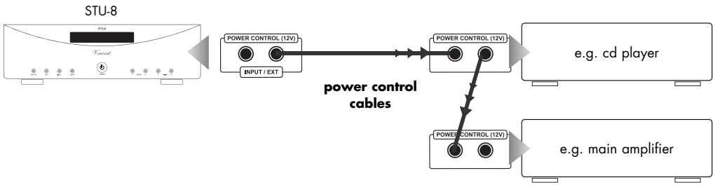

Many devices which can be controlled by a switching signal (not preamplifiers or integrated amplifiers), have two terminals which do not differentiate between input and output. In this case either of the two can be selected. Even some devices that transmit the switch signal (preamplifiers and integrated preamplifiers) lack this marking. In this case it may be assumed that they both are signal outputs. "POWER CONTROL" sockets of preamplifiers or integrated amplifiers must not be interconnected! All receiving devices must not be connected to more than one preamplifier or integrated amplifier (directly or indirectly)! If a "POWER CONTROL" cable is connected to the back of the main amplifier and the 12V switching signal is given, the main amplifier can no longer be switched off with the "POWER" button. If the power control function is not desired, the switch signal cable must therefore be removed!
| Action | Description |
| Hear FM stations | 1. Press the POWER button (8) key to turn on the device. 2. On the display, press the DAB / FM button (4 / 18) to select the FM band transmitter. 3. Select the desired channel. a. Auto tuning selection With the AUTO button (5 / 19) automatically set a station. If a station has been set, the process stops automatically. b. Manual tuning To set a channel, press the TUNING button (10/23) - the frequency steps hold 50kHz. |
| Mono/Stereo Mode | If a Stereo sound transmitter has been set, press the ENTER key (7 / 21) to switch between mono and stereo. To compensate a weak FM stereo reception, select the mono mode and the reception is done with less noise. |
| RDS Info Display History | With "Auto Tuning" (5 / 19) or "Manual tuning" (10/23) with a frequency RDS signal and adjust to the INFO button (6 / 20) button to start the RDS reception and the display runs each time you press the Info button. This data is transmitted from the transmitter: a. Program Name b. Radio Text c. Program Type d. Date and Time |
| Preset Transmitter sites | a. Adjust "Auto Tuning" (5 / 19) or "Manual tuning" of the transmitter which is entered in the memory. b. Press and hold the channel buttons (16) on the remote control for 2 seconds, then the display shows "Preset XX saved" and the process is running. |
| Action | Description |
| Hear DAB stations | 1. Press the POWER button (8) to turn on the device. 2. Press the display, DAB / FM button (4 / 18) to select the DAB transmitter band 3. A channel scan starts automatically (see next action). 4. Press the TUNING button (10/23) to set the received station. If the desired channel is displayed, press the ENTER key (7 / 21) to listen. |
| Use of DAB on startup | · When you turn on the device for the first time and select DAB, it automatically scans the Tuning function Band III (7A-13B) frequencies. After the tuning the first found channel appears. · Press the AUTO button (5 / 19) and release in less than 2 seconds, to select program Band III (7 A~13B). Press the AUTO button (5 / 19) longer than 2 seconds and then release them to carry out the full channel search (complete band III and/band: 5A to LW) When the automatic channel search is complete, set the number of channels displayed, and the first channel. · When the signal N / A "appears, check the antenna connection. · Perform a system reset if they use the STU-8 or new location transmitter, connected to receive program bouquets. |
| Full display | Hold the INFO button (6 / 20) for 2 seconds. · Manual Tune (Manual tuning) · System Reset · Software Version |
| Manual Tune | Press and hold the INFO button (6 / 20) for 2 seconds and then confirm by pressing the ENTER key (7 / 21). Now use the TUNING buttons (10/23) to search the transmitter manually. |
| System Reset | To adjust the tuner with the local DAB transmitter, press the INFO button (6 / 20) for 2 Seconds till the display appears as "Manual Tune", then press the INFO button again, the display shows "System Reset" then press on the Enter (deletion of the memory is inzw. completed) which leads to the tuner for a faster channel search and select from the locally available stations. |
| Auto Enter | Press the ENTER key (7 / 21) for 2 seconds, turn the Auto Input on or off. Thus, the station will be found after a automatic search is audible without pressing the ENTER key (hear see "DAB station"). |
| Vendor text (Stream) | Press when you receive a text, the information provider key (6 / 20) to between to change the individual broadcast information of the provider. |
| Set Autoscan | Press the AUTO button (5 / 19) for a quick scan (The band III Channel between 7A ~13B). when the AUTO button is pressed longer than 2 seconds, is a Full Scan (Full band III 5A 13Fand ~ LW LA L-band). |
| Preset Sender | a. With the "Manual Tune" / auto mode, the transmitter in the memory. b. Press the Preset channel keys (16) on the remote control for 2 seconds the display shows "Preset XX Saved" while the operation is carried out. |
DAB FREQUENCY TABLE
Band III (174 to 240 Mhz)
| level | Frequency | level | Frequency | level | Frequency |
| 5A | 174.928 MHz | 8B | 197.648 MHz | 11C | 220.352 MHz |
| 5B | 176.640 MHz | 8C | 199.360 MHz | 11D | 222.064 MHz |
| 5C | 178.352 MHz | 8D | 201.072 MHz | 12A | 223.936 MHz |
| 5D | 180.064 MHz | 9A | 202.928 MHz | 12B | 225.648 MHz |
| 6A | 181.936 MHz | 9B | 204.640 MHz | 12C | 227.360 MHz |
| 6B | 183.648 MHz | 9C | 206.352 MHz | 12D | 229.072 MHz |
| 6C | 185.360 MHz | 9D | 208.064 MHz | 13A | 230.784 MHz |
| 6D | 187.072 MHz | 10A | 209.936 MHz | 13B | 232.496 MHz |
| 7A | 188.928 MHz | 10B | 211.648 MHz | 13C | 234.208 MHz |
| 7B | 190.640 MHz | 10C | 213.360 MHz | 13D | 235.776 MHz |
| 7C | 192.352 MHz | 10D | 215.072 MHz | 13E | 237.488 MHz |
| 7D | 194.064 MHz | 11A | 216.928 MHz | 13F | 239.200 MHz |
| 8A | 195.936 MHz | 11B | 218.640 MHz |
L-Band (1452 to 1490 Mhz)
| level | Frequency | level | Frequency | level | Frequency |
| LA | 1452.960MHz | LI | 1466.656MHz | LQ | 1480.352MHz |
| LB | 1454.672MHz | LJ | 1468.368MHz | LR | 1482.064MHz |
| LC | 1456.384MHz | LK | 1470.080MHz | LS | 1483.776MHz |
| LD | 1458.096MHz | LL | 1471.792MHz | LT | 1485.488MHz |
| LE | 1459.808MHz | LM | 1473.504MHz | LU | 1487.200MHz |
| LF | 1461.520MHz | LN | 1475.216MHz | LV | 1488.912MHz |
| LG | 1463.232MHz | LO | 1476.928MHz | LW | 1490.624MHz |
| LH | 1464.944MHz | LP | 1478.640MHz |
TIPS
Burn in/ Warm up
Your audio components need a certain time period until they reach maximum performance. The duration of this "warm up" time is very different for the various elements of your audio system. Higher and homogeneous sound quality is achieved while keeping the device switched on.
Your audio specialist dealer has enough experience to give you more information.
Net frequency noise
Some audio source devices may in combination with the amplifier cause a humming noise at power line frequency audible from your speakers. Usually, its volume varies with the volume setting of the amplifier. This is no sign of a defect or fault of your audio products but has to be eliminated. Generally, every wall-powered device connected to the ground wire of the power plug can cause this problem when connected to the amplifier.
Experience shows that this problem is mainly caused by antenna-connected components (as TV-sets or Tuners), personal computers, electrostatic loud
speakers, subwoofoers, record players or headphone amplifiers that are connected to the audio inputs of the amplifier. Another possible reason for humming noise is electromagnetic interference of other components' power supplies with pick-up systems of record players (change the place of the record player for a test).
In most electric devices the ground potentials of all signals are connected to each other at one central point, where they have one common connection. If the device uses the protective conductor of the wall outlet, the corresponding wire of the line cord is connected intractably to the metal housing of the device. This is the mostly the point where the central grounding point is attached to. By doing this the housing is able to shield all signals from external radiated noise. Some main amplifiers are equipped with a "Ground Lift"-switch. If it is activated, ground potential of the chassis and the protective ground wire are being separated from the central signal ground point. The protective ground wire keeps its function. Sometimes this helps prevent noise caused by errors in grounding.
If the problem occurs and cannot be solved by yourself your audio specialist dealer will help you.
TROUBLESHOOTING
| Symptom | Possible Cause | Remedy |
| Does not work after pressing the power switch | Power cable is not connected to a suitable outlet. Power cord is not plugged firmly into the socket and the socket or faulty equipment. Fuse or device is defective. | Make a connection to a working electrical outlet with the appropriate mains voltage. Check the power cord, replace it if necessary with a suitable mains cable and press the plug firmly into the socket and on the other side into the power jack on the device.. Contact your local dealer. |
| No sound, LED "warm up" lights (1) | Output of the tuner or not wrong or not with the desired input port of the amp. There is no set frequency on which a transmitter can be received with a strong enough signal. It was not appropriate, to join the band corresponding to the antenna tuner. Wrong input channel selected at the amplifier. Volume of the amplifier is set too low. | Correct the connection to the tuner. Adjust the frequency in a better transmitter. Try for MW reception, adjust the antenna better. Attach a suitable antenna (11). Correct the input selector on the amplifier. Carefully increase the volume on the amplifier. |
| Audio playback of a channel does not work | One of the signal cable between the tuner and amplifier is not firmly plugged in or faulty. | Check and tighten the cable. |
| Poor reception or no reception | No Antenna or not connected properly. Interference sources are nearby. The signal of the FM transmitter is too weak (may be too far away station). | Check the connection to the selected mode (FM) associated antenna (11). Try to locate the fault and eliminate. Try to improve it by pressing "ENTER" (7/21) to receive or look for another station. |
TROUBLESHOOTING
| Symptom | Possible Cause | Remedy |
| No RDS | The station does not support RDS. | Do not use this service or ask one another FM-/DAB- Channel. |
| Poor sound quality | The cable connections are loose, dirty connections, a cable is defective or poor reception. | Check the audio connections or switch with the ENTER key (7 / 21) to mono mode. |
| Functions cannot be executed using remo-te control | No batteries in the handset, batteries not pro-perly installed or used.The line of sight between the remote and the unit is obstructed, the range was exceeded, or the handset is pressed too far lateral positionDevice is not turned on. | Check and replace batteries if necessary.Try the remote control only in open space on the front panel, within 7m distance and if possible, facing the device.Turn on the device. |
| To hear low-frequency hum | See the "hum" in the chapter "Tips". | See the "hum" in the chapter "Tips". |
| Transmitter is in stereo, but is only returned in mono | The stereo / mono setting on the tuner is faulty. | Press the ENTER key (7 / 21). |
If normal function is not possible, device short from the socket off and try again.
TECHNICAL DATA
FM Tuner Part
Frequency:
RF-Sensitivity:
Frequency Characteristics:
SNR:
Total harmonic distortion
Mono 1 kHz (around 75kHz ):
Stereo distance1 kHz (WIDE):
Antenna inputs:
87.5 MHz~108.0 MHz
0.8 μV
30 Hz ~ 15 kHz(+1 dB/-1.5dB)
62 dB (Mono)
0.12%
35 dB
75 Ω/ohm, Coax (Male)
DAB Tuner Part
Frequency:
approx.174.928 (5A) 239.200 (13F)
MHz (VHF BAND III)
1452.960 (LA) ~ 1490.624 (LW) MHz (LBAND)
97 dBm(VHF), -96dBm(L-BAND)
40 dB
101dBm
100dBm
0.01% (1 kHz)
2 Vrms
88 dB (1 kHz)
20Hz 20kHz(+0.5 / 0.5dB)
50 /Ohm, F (Female)
Sensitivity:
Adjacent channel selection:
Receiver sensitivity:
SNR:
THD+N:
Analogue output:
Channel separation:
Frequency range:
Antenna:
General
Dimensions(BxHxT):
Weight (Net):
Color:
430× 133× 359(mm)
9kg
Silver/Black
GLOSSARY
Audio Sources/Source devices
These are the components of your HiFi system and all other appliances, whose sound you want to hear over the system and are thus connected to the pre-amplifier, amplifier or receiver. This includes CD players, DVD players, tuners (radians), cassette players, DAT recorders, personal computers, record players, portable audio devices and many more.
Dynamic
The volume difference between the quietest and the loudest sounds possible in audio signals (without distortion or transition to noise).
Input sensitivity
Term for the smallest average (RMS) input voltage which causes the maximum output power at the maximum volume setting on the amplifier. Examples: 100mV to 500mV (Millivolts) on high level inputs, 2mV to 5mV on the phono MM input or 0.1mV to 0.5mV on the phono MC input.
dB Level
This is a way of describing any physical quantity; it is a common measurement for signal voltages and the volume. It is given in decibels (dB). Alternating signal voltages below 1V (RMS) are described as "line level" voltages, which are suitable as music signals for amplifier inputs. Inputs on amplifiers (mostly represented by RCA sockets), which are designed for signals on the CD player, tape recorder, DVD player etc. are also referred to as "line level inputs" or "high-level inputs". Those signal inputs must not be confused with inputs that accept preamplified signals.
RCA
RCA is the American name for coaxial RCA connectors and sockets, originally the abbreviation for "Radio Corporation of America", the name of a United States company. Both the plug and cable consist of a rod-shaped inner lead and a cylindrical-shaped outer lead. This enables a mono audio signal or a video signal to be transmitted. Compared to the XLR plug connector, this type of connection is also called "unbalanced signal connection".
XLR
Also: "Symmetrical Connection" or "balanced". A plug-and-socket connection for audio devices. It is round (with approx. 1.5cm in diameter) and has 3 contacts/pins. XLR is an alternative connection to RCA used to transmit NF-Signals in professional audio equipment. The advantage is one additional transmission path for the same but phase inverted signal. If the receiving device can process this, all inducted noise received in the cable screen can be eliminated. The signal voltage level used for this type of transfer is higher, so it is a more robust less sensitive signal path.
CONSIGNES DE SECURITE
- Système US (Pin 2 = COLD, Pin 3 = HOT)
75 Ω/ohm, Coax (male)
Please keep the receipt, store it together with this manual. The receipt is your proof for the beginning of the warranty period. Note the serial number in the following box, you can read it from the rear side of the device.
www.sintron-audio.de