USER MANUAL HT 40 PRO AKG
Please read the manual before using the equipment!
MODE D'EMPLOI p.26
1 Safety and Environment 16
1.1 Safety 16
1.2 Environment 16
2 Description. 17
2.1 Introduction 17
2.2 Packing Lists 17
2.3 Optional Accessories 17
2.4 HT 40 PRO Handheld Transmitter 17
2.4.1 Controls 17
2.5 HT 40 FLEXX Handheld Transmitter 18
2.5.1 Controls 18
3 Setting Up 28
3.1 Inserting and Testing Batteries (HT 40 PRO and HT 40 FLEXX) 19
3.2 Setting Up the HT 40 PRO 19
3.3 Setting Up the HT 40 FLEXX 20
3.4 Replacing the Color Code Clip (HT 40 PRO and HT 40 FLEXX) 20
3.5 Before the Soundcheck (HT 40 PRO and HT 40 FLEXX) 20
3.6 Multichannel Systems (HT 40 FLEXX + SR 40 FLEXX) 20
3.7 Changing Carrier Frequencies 21
4 Microphone Technique 22
4.1 Introduction 22
4.2 Working Distance and Proximity Effect 22
4.3 Angle of Incidence 22
4.4 Feedback 22
4.5 Backing Vocals 23
5 Cleaning 23
5.1 Surfaces 23
5.2 Internal Windscreen (HT 40 PRO and HT 40 FLEXX) 23
6 Troubleshooting 24
7 Specifications 25
Fig. 8 74
FCC Statement
This equipment has been tested and found to comply with the limits for a Class B digital device, pursuant to Part 74 of the FCC Rules. These limits are designed to provide reasonable protection against harmful interference in a residential installation. This equipment generates, uses, and can radiate radio frequency energy and, if not installed and used in accordance with the instructions, may cause harmful interference to radio communications. However, there is no guarantee that interference will not occur in a particular installation. If this equipment does cause harmful interference to radio or television reception, which can be determined by turning the equipment off and on, the user is encouraged to try to correct the interference by one or more of the following measures:
Reorient or relocate the receiving antenna.
- Increase the separation between the equipment and the receiver.
- Connect the equipment into an outlet on a circuit different from that to which the receiver is connected.
Consult the dealer or an experienced radio/TV technician for help.
Shielded cables and I/O cords must be used for this equipment to comply with the relevant FCC regulations.
Changes or modifications not expressly approved in writing by AKG Acoustics may void the user's authority to operate this equipment.
This device complies with Part 15 of the FCC Rules. Operation is subject to the following two conditions: (1) this device may not cause harmful interference, and (2) this device must accept any interference received, including interference that may cause undesired operation.

1.1 Safety
1 Safety and Environment
- Dispose of dead dry or rechargeable batteries conforming to local waste disposal rules. Never throw dry or rechargeable batteries into a fire (risk of explosion).
- Do not spill any liquids on the equipment and do not drop any objects through the ventilation slots in the equipment.
- The equipment may be used in dry rooms only.
- The equipment may be opened, serviced, and repaired by authorized personnel only. The equipment contains no user-serviceable parts.
- Do not place the equipment near heat sources such as radiators, heating ducts, or amplifiers, etc. and do not expose it to direct sunlight, excessive dust, moisture, rain, mechanical vibrations, or shock.
- Clean the equipment with a moistened (not wet) cloth only. Never use caustic or scouring cleaners or cleaning agents containing alcohol or solvents since these may damage the enamel and plastic parts.
- Use the equipment for the applications described in this manual only. AKG cannot accept any liability for damages resulting from improper handling or misuse.

1.2 Environment
- When scrapping the equipment, separate the case, circuit boards, and cables, and dispose of all components in accordance with local waste disposal rules.
- The packaging of the equipment is recyclable. Dispos of the packaging in an appropriate container provided by the local waste collection/recycling entity and observe all local legislation relating to waste disposal and recycling.
2 Description

2.1 Introduction
Thank you for purchasing an AKG product. This Manual contains important instructions for setting up and operating your equipment. Please take a few minutes to read the instructions below carefully before operating the equipment. Please keep the Manual for future reference. Have fun and impress your audience!
1 HT 40 PRO or HT 40 FLEXX handheld transmitter
1 stand adapter
1 AA size battery
1 semitransparent color clip
1 Manual Supplement sheet
- Check that the packaging contains all of the items listed for your system. Should any of these items be missing, please contact your AKG dealer.
- For optional accessories, refer to the current AKG catalog or folder, or visit www.akg.com. Your dealer will be glad to help.
The HT 40 PRO handheld transmitter operates on a single fixed, quartz stabilized frequency in the 660 MHz to 865 MHz UHF carrier frequency range and uses an antenna integrated in the body.
The microphone element permanently mounted on the transmitter uses a high quality cardioid transducer from AKG. It provides low handling noise sensitivity, high gain before feedback, and brilliant sound quality, as well as a built-in wind and pop filter to reduce wind and breath noise.
2.2 Packing List
2.3 Optional Accessories
2.4 HT 40 PRO
Handheld Transmitter
2.4.1 Controls
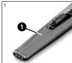
Refer to fig. 1.
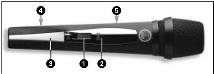
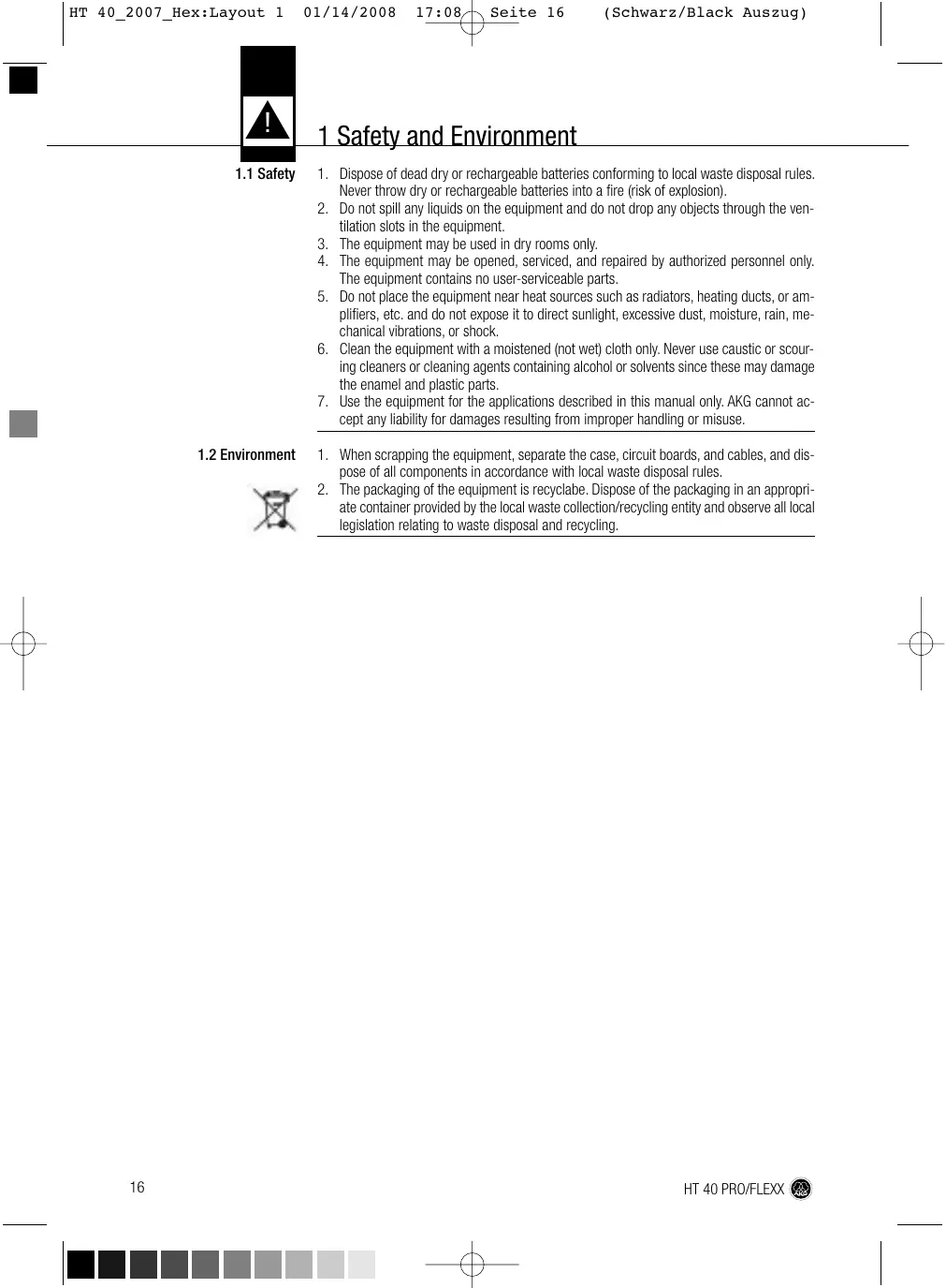
Fig. 1: Controls on HT 40 PRO handheld transmitter
1 On/off switch: This slide switch provides three positions indicated in the display window:
ON: Power to the transmitter is on.
MUTE: The signal delivered by the microphone element is muted while power and the RF carrier frequency remain on.
OFF: Power to the transmitter is off.
2 Status LED: Indicates the transmitter's operating status.
LED lit green: Battery is OK.
LED lit red: From the moment the LED changes to red, the battery capacity will provide a maximum of two operating hours. We recommend replacing the battery with a new one as soon as possible.
- If you use a rechargeable battery, the LED will change to red 15 minutes before the battery will be dead!
3 Color code clip: The color of this plastic clip indicates the carrier frequency of your transmitter. Receiver channels tuned to the same frequency are marked with the same color. Refer to the Manual Supplement sheet for a color code table.
You can remove the color code clip on the HT 40 PRO and replace it with the supplied semitransparent clip.
Note:

2 Description
2.5 HT 40 FLEXX Handheld Transmitter
4 Battery compartment lid: Refer to section 3.1.
5 Carrier frequency label: The label above the battery compartment indicates the carrier frequency and approval marks of your transmitter.
Operating in the 660 MHz to 865 MHz UHF range, the HT 40 FLEXX provides three selectable, quartz stabilized carrier frequencies within the 3-MHz-wide frequency band for which you ordered your WMS 40 FLEXX. The antenna is integrated in the body.
The microphone element permanently mounted on the transmitter uses a high quality cardioid transducer from AKG. It provides low handling noise sensitivity, high gain before feedback, and brilliant sound quality, as well as a built-in wind and pop filter to reduce wind and breath noise.
2.5.1 Controls
Refer to fig. 2.
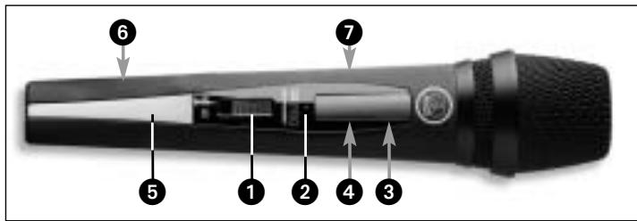
Fig. 2: Controls on HT 40 FLEXX handheld transmitter
1 On/off switch: This slide switch provides three positions:
ON: Power to the transmitter is on.
MUTE: The signal delivered by the microphone element is muted while power and the RF carrier frequency remain on.
OFF: Power to the transmitter is off.
2 Status LED: Indicates the transmitter's operating status.
LED lit green: Battery is OK.
LED lit red: From the moment the LED changes to red, the battery capacity will provide a maximum of two operating hours. We recommend replacing the battery with a new one as soon as possible.
Note:
If you use a rechargeable battery, the LED will change to red 15 minutes before the battery will be dead!
3 Frequency selector: This slide switch tunes the transmitter to one of three different carrier frequencies within the transmitter's carrier frequency band.
4 GAIN: This slide switch sets the transmitter's audio input gain in two stages, "HIGH" (high gain) or "LOW" (low gain).
5 Color code clip: The color of this plastic clip indicates the carrier frequency band of your transmitter. Receivers tuned to the same frequency band are marked with the same color. Refer to the Manual Supplement sheet for a color code table.
You can remove the color code clip on the HT 40 FLEXX and replace it with the supplied semitransparent clip.
6 Battery compartment lid: Refer to section 3.1.
7 Carrier frequency label: The label above the battery compartment indicates the name of the carrier frequency band and the three carrier frequencies of your transmitter.
3 Setting Up
3.1 Inserting and Testing Batteries (HT 40 RPO and HT 40 FLEXX)
- Depress the snap hook on the battery compartment lid (1).
- Pull the battery compartment lid (1) off the transmitter in the direction of the arrow.
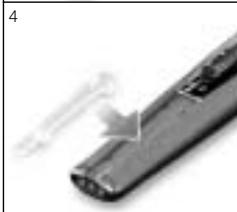
- Insert the supplied battery (2) into the battery compartment conforming to the polarity marks.
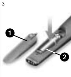
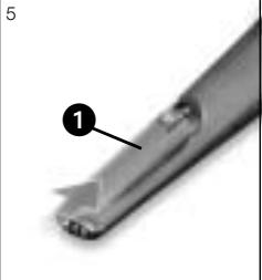
Fig. 3: Inserting batteries into the HT 40 PRO or HT 40 FLEXX handheld transmitter.
The transmitter will not function if you insert the battery the other way round.
- Set the on/off switch to "ON" to switch power to the transmitter on. If the battery is in good condition, the status LED will be lit green. If the status LED) is lit red, the battery will be dead within about two hours. Replace the battery with a new one as soon as possible.
- If you use a rechargeable battery, the LED will switch to red 15 minutes before the battery will be dead!
If the status LED fails to illuminate the battery is dead. Insert a new battery.
-
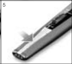
To close the battery compartment, slide the battery compartment lid (1) onto the battery compartment from below to the point that the snap hook will engage.
-
Switch power to the receiver (SR 40 SINGLE or DUAL) on.
- To switch power to the transmitter on, set the on/off switch to "ON".
- Since the HT 40 PRO handheld transmitter has been designed specifically for the integrated microphone element, there is no need to set gain on the handheld transmitter. Therefore, the handheld transmitter has no level or gain control.
- Switch power to your sound system or amplifier on.
- Talk or sing into the microphone and set the levels on your mixer or amplifier referring to the appropriate instruction manual, or by ear.
- Set the frequency selector on the transmitter and the frequency selector on the SR 40 FLEXX receiver to the same positions (1 - 1, 2 - 2, or 3 - 3). If you tune the transmitter and receiver to different frequencies, no signal will be transmitted!
- Set the SQUELCH control on the SR 40 FLEXX receiver to minimum and switch power to the receiver on.
- To switch power to the transmitter on, set the on/off switch to "ON".
- Switch power to your sound system or amplifier on.
-
Talk or sing into the microphone, watching the AF LEDs on the receiver.
-
If the OK LED flashes rarely and the CLIP LED will not flash at all, the transmitter input gain is too low. Set GAIN to "HIGH".
Refer to fig. 3.
Note:
3.2 Setting Up the HT 40 PRO
Note:
Also refer to section 4 Microphone Technique.
3.3 Setting Up the HT 40 FLEXX
Also refer to section 4 Microphone Technique.
3 Setting Up
-
If OK (6a) is lit constantly and CLIP (6b) flashes frequently or is lit constantly, the transmitter input gain is too high. Set GAIN (18) to "LOW".
-
Set the levels on your mixer or amplifier referring to the appropriate instruction manual, or by ear.
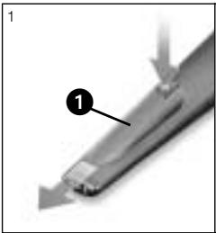
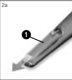
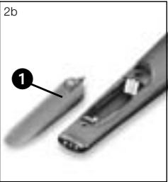
3.4 Replacing the Color Code Clip (HT 40 PRO and HT 40 FLEXX)
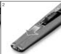
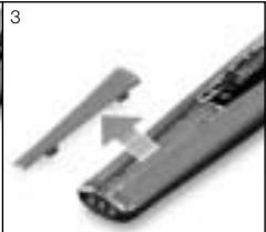
Fig. 4: Replacing the color code clip on the transmitter.
Refer to fig. 4, 1-3. Refer to fig. 4, 4-5.
3.5 Before the Soundcheck (HT 40 PRO and HT 40 FLEXX)
- Pull the color code clip (1) off the transmitter case in the direction of the arrow.
-
Slide the supplied semitransparent replacement clip onto the transmitter to the point that it snaps into place with an audible click.
-
SR 40 FLEXX only.
-
Move the transmitter around the area where you will use the system to check the area for "dead spots", i.e., places where the field strength seems to drop and reception deteriorates.
If you find any dead spots, try to eliminate them by repositioning the receiver. If this does not help, avoid the dead spots.
- The RF OK LED on the receiver going out means no signal is being received or the squelch* is active.
Switch the transmitter on, move closer to the receiver, or set the squelch threshold* to the point that the green RF OK LED will be lit.
- HT 40 FLEXX + SR 40 FLEXX: If the received signal is noisy, set the squelch threshold to a level where the noise will stop.

3.9 Multichannel Systems (HT 40 FLEXX + SR 40 FLEXX)
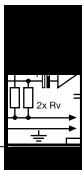
- HT 40 FLEXX + SR 40 FLEXX: Never set the squelch threshold any higher than absolutely necessary. The higher the squelch threshold (-70dB = ., -100dB = .) , the lower the sensitivity of the receiver and thus the usable range between transmitter and receiver.
Note:
In each frequency band, the spacing between the three carrier frequencies of all WMS 40 FLEXX transmitters and receivers is wide enough for operating three radio channels simultaneously with no mutual interference.
Refer to fig. 8 on page 74.
For systems with up to nine channels you will need WMS 40 FLEXX kits in up to three different frequency bands. Please ask your dealer which frequency bands are suited for multichannel use and approved for the place where you will use the system. Perform steps 1 through 6 below for each frequency band separately.
- Switch power to all transmitters and receivers off.
- Set the frequency selectors on the transmitter and receiver for channel 1 to "1".
- Set the frequency selectors on the transmitter and receiver for channel 2 to "2".
3 Setting Up
- Set the frequency selectors on the transmitter and receiver for channel 3 to "3".
- Set up the transmitter and receiver for channel 1.
-
Repeat steps 1 through 5 for channels 2 and 3.
-
Never operate two or more wireless channels on the same frequency at the same time and location. This would cause unwanted noise due to radio interference.
- Prior to changing a carrier frequency, be sure to switch the transmitter off. To activate the new carrier frequency, switch the transmitter back on.

3.7 Changing
Carrier Frequencies

4.1 Introduction
4 Microphone Technique
A handheld vocal microphone provides many ways of shaping the sound of your voice as it is heard over the sound system.
The following sections contain useful hints on how to use your HT 40 Pro or HT 40 FLEXX handheld transmitter for best results.
4.2 Working Distance and Proximity Effect
Basically, your voice will sound the bigger and mellower, the closer you hold the microphone to your lips. Moving away from the microphone will produce a more reverberant, more distant sound as the microphone will pick more of the room's reverberation.
You can use this effect to make your voice sound aggressive, neutral, insinuating, etc. simply by changing your working distance.
Proximity effect is a more or less dramatic boost of low frequencies that occurs when you sing into the microphone from less than 2 inches. It gives more "body" to your voice and an intimate, bass-heavy sound.
4.3 Angle of Incidence
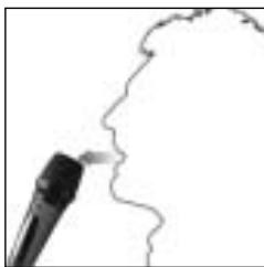
Sing to one side of the microphone or above and across the microphone's top. This provides a well-balanced, natural sound.
If you sing directly into the microphone, it will not only pick up excessive breath noise but also overemphasize "sss", "sh", "tch", "p", and "t" sounds.
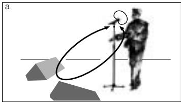
Fig. 5: Sing across the microphone's top.
4.4 Feedback
Fig. 6: Never point any microphone at a monitor!
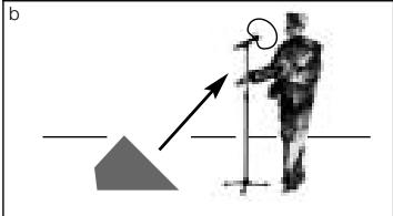
Feedback is the result of part of the sound projected by a speaker being picked up by a microphone, fed to the amplifier, and projected again by the speaker. Above a specific volume or "system gain" setting called the feedback threshold, the signal starts being regenerated indefinitely, making the sound system howl and the sound engineer desperately dive for the master fader to reduce the volume and stop the howling.
To increase usable gain before feedback, the microphone elements of the HT 40 FLEXX and HT 40 PRO handheld transmitters have a cardioid polar pattern. This means that the microphone is most sensitive to sounds arriving from in front of it (your voice) while
picking up much less of sounds arriving from the sides or rear (from monitor speakers for instance).
To maximize gain before feedback, place the main ("FOH") speakers in front of the microphones (along the front edge of the stage).
If you use monitor speakers, be sure never to point any microphone directly at the monitors, or at the FOH speakers.
Feedback may also be triggered by resonances depending on the acoustics of the room or hall. With resonances at low frequencies, proximity effect may cause feedback. In this case, it is often enough to move away from the microphone a little to stop the feedback.
4 Microphone Technique
- Never let more than two persons share a microphone.
- Ask your backing vocalists never to sing more than 35 degrees off the microphone axis.
The microphone is very insensitive to off-axis sounds. If the two vocalists were to sing into the microphone from a wider angle than 35 degrees, you may end up bringing up the fader of the microphone channel far enough to create a feedback problem.
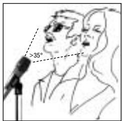

4.5 Backing Vocals
Fig. 7: Two vocalists max., 35 degrees max.

5.2 Internal Windscreen (HT 40 PRO and HT 40 FLEXX)
5.1 Surfaces
5 Cleaning
-
Use a soft cloth moistened with water to clean the surfaces of the HT 40 PRO and HT 40 FLEXX transmitters.
-
Unscrew the wire-mesh cap of the handheld transmitter CCW and remove the wire-mesh cap from the transmitter.
- Remove the windscreen (foam sheet) from the wire-mesh cap.
- Wash the windscreen in mild soap suds.
- As soon as the windscreen has dried, replace it in the wire-mesh cap and screw the wire-mesh cap back onto the transmitter CW.
6 Troubleshooting
| Problem | Possible Cause | Remedy |
| No sound. | 1. AC adapter is not connected to receiver and/or power outlet.
2. Receiver is OFF.
3. Receiver is not connected to mixer or amplifier.
4. VOLUME control on receiver is at zero.
5. Microphone or instrument is not connected to bodypack transmitter.
6. Transmitter is tuned to different frequency than receiver.
7. Transmitter on/off switch is at "OFF" or "MUTE".
8. Transmitter batteries are not inserted properly.
9. Transmitter batteries dead.
10. Transmitter is too far away from receiver or squelch threshold setting is too high.
11. Obstructions between transmitter and receiver.
12. Receiver is invisible from transmitter location.
13. Receiver is too close to metal objects. | 1. Connect AC adapter to receiver and/or power outlet.
2. Push ON/OFF switch to switch receiver ON.
3. Connect receiver output to mixer or amplifier input.
4. Turn up VOLUME control.
5. Connect microphone or instrument to audio input on bodypack.
6. Tune transmitter and receiver to same frequency.
7. Set transmitter on/off switch to "ON".
8. Insert batteries conforming to "+" and "-" marks.
9. Replace batteries.
10. Move closer to receiver or reduce squelch threshold setting.
11. Remove obstructions.
12. Avoid spots where you cannot see receiver.
13. Move receiver away from or remove interfering objects. |
| Noise, crackling, unwanted signals. | 1. Antenna location.
2. Interference from other wireless systems, TV, radio, CB radios, or defective electrical appliances or installations. | 1. Relocate receiver.
2. Switch off interference sources or defective appliances, use a WMS 40 SINGLE/DUAL tuned to a different frequency, or switch WMS 40 FLEXX to different frequency; have electrical installation checked. |
| Distortion. | 1. GAIN control is set too high or too low.
2. Interference from other wireless systems, TV, radio, CB radios, or defective electrical appliances or installations. | 1. Set GAIN to alternative position.
2. Switch off interference sources or defective appliances, use a WMS 40 SINGLE/DUAL tuned to a different frequency, or switch WMS 40 FLEXX to different frequency; have electrical installation checked. |
| Momentary loss of sound ("drops") at some locations within performance area. | • Antenna location. | • Relocate receiver. If dead spots persist, mark and avoid them. |

7 Specifications

HT 40 PRO and HT 40 FLEXX
| Carrier frequency range: | 660 to 865 MHz; HT 40 FLEXX: 3 selectable frequencies |
| Modulation: | FM |
| Audio bandwidth: | 65 to 20,000 Hz |
| Frequency stability(-10°C to +50°C): | ±15 kHz |
| Rated deviation: | 15 kHz |
| T.H.D. at 1 kHz: | typ. 0.8% |
| Compander: | Yes |
| Signal/noise ratio: | typ. 110 dB(A) |
| RF output: | 10 mW |
| Current consumption: | typ. 70 mA |
| Power requirement: | 1 x 1.5 V AA size battery (LR 6 to IEC 86-L) |
| Battery life: | typ. 31 hours (for 2200 mAh) |
| Size: | 229 x 53 x 53 mm (9 x 2.1 x 2.1 in.) |
| Net weight: | 214 g (7.6 oz.) |
This product conforms to the standards listed in the Declaration of Conformity. To order a free copy of the Declaration of Conformity, visit http://www.akg.com or contact sales@akg.com.
Page
For other products and distributors worldwide visit www.akg.com


ROHS OK
HA Harman International Company
Technische Änderungen vorbehalten. Specifications subject to change without notice. Ces caractéristiques sont susceptibles de modifications. Ci riserviamo il diritto di effettuare modifiche tecniche. Nos reservamos el dato de introduir modificaciones tícnicas. Especificações sujeitas a mudancas sem avis prévio.
Printed in China (P.R.C.)
01/08/9100 U 12670