
640I - Paint gun TITAN - Free user manual and instructions
Find the device manual for free 640I TITAN in PDF.
| Product Type | Airless Paint Sprayer |
| Brand | TITAN |
| Model | 640I |
| Maximum Working Pressure | 3200 psi (221 bar) |
| Maximum Flow Rate | 0.57 gpm (2.2 L/min) |
| Motor | 1.3 hp DC Motor |
| Power Supply | 115 V AC, 60 Hz, 15 A min. circuit |
| Weight | 15.9 kg (35 lb) |
| Maximum Recommended Tip | 0.023 inch |
| Maximum Recommended Hose | 91.4 m (300 ft) |
| Maximum Recommended Power Cord | 91.4 m (300 ft) |
| Pressure Indicator | Electronic (flashing yellow, solid yellow, solid green) |
| Pressure Relief Procedure | Yes, manual via PRIME/SPRAY valve |
| Maintenance | Filters, motor brushes, gears, fluid section |
| Warranty | 25 months against defects in materials and workmanship |
Frequently Asked Questions - 640I TITAN
User questions about 640I TITAN
0 question about this device. Answer the ones you know or ask your own.
Ask a new question about this device
Download the instructions for your Paint gun in PDF format for free! Find your manual 640I - TITAN and take your electronic device back in hand. On this page are published all the documents necessary for the use of your device. 640I by TITAN.
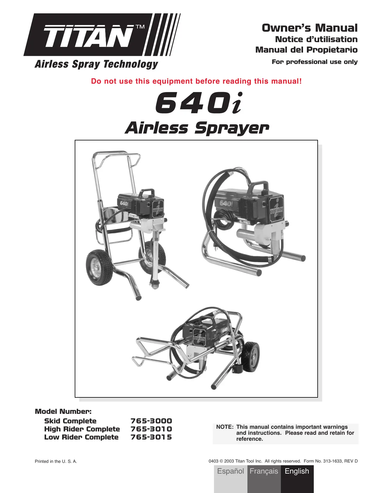
USER MANUAL 640I TITAN
Do not use this equipment before reading this manual!
640i
Airless Sprayer
Model Number:
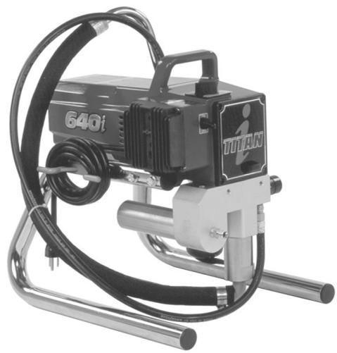
Skid Complete
765-3000
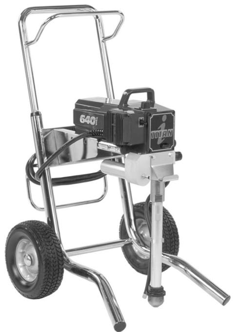
High Rider Complete
765-3010
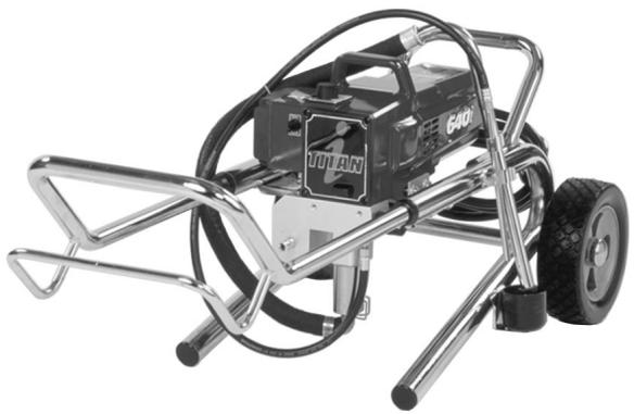
Low Rider Complete
765-3015
NOTE: This manual contains important warnings and instructions. Please read and retain for reference.
Table of Contents
Safety Precautions 2
General Description 4
Operation 4
Setup 4
Preparing to Paint 4
Painting 5
Electronic Pressure Control Indicators 5
Pressure Relief Procedure 6
Spraying 6
Spraying Technique 6
Practice 7
7
Maintenance 7
General Repair and Service Notes. 7
Replacing the Motor 8
Replacing the Motor Brushes 8
Replacing the Gears 8
Replacing the Transducer. 9
Replacing the PRIME/SPRAY Valve. 9
Servicing the Fluid Section 10
Replacing the Filters 11
Troubleshooting 12
Warranty 13
Parts Listings 38
Main Assembly. 38
Motor Assembly 39
Gear Box Assembly 40
Fluid Section Assembly 42
Suction Set Assembly 44
Stand Assembly 44
Low Rider Assembly 45
High Rider Assembly 46
Siphon Tube Assembly (High Rider Assembly) 46
Accessories 47
Electrical Schematic 49
Safety Precautions
This manual contains information that must be read and understood before using the equipment. When you come to an area that has one of the following symbols, pay particular attention and make certain to heed the safeguard.
WARNING
This symbol indicates a potential hazard that may cause serious injury or loss of life. Important safety information will follow.
CAUTION
This symbol indicates a potential hazard to you or to the equipment. Important information that tells how to prevent damage to the equipment or how to avoid causes of minor injuries will follow.
NOTE: Notes give important information which should be given special attention.
WARNING
HAZARD: Injection injury - A high pressure fluid stream produced by this equipment can pierce the skin and underlying tissues, leading to serious injury and possible amputation. See a physician immediately.
DO NOT TREAT AN INJECTION INJURY AS A SIMPLE CUT! Injection can lead to amputation. See a physician immediately.
The maximum operating range of the sprayer is 3200 PSI/221BAR fluid pressure.
PREVENTION:
-
NEVER aim the gun at any part of the body.
-
NEVER allow any part of the body to touch the fluid stream. DO NOT allow body to touch a leak in the fluid hose.
- NEVER put hand in front of the gun. Gloves will not provide protection against an injection injury.
- ALWAYS lock gun trigger, shut pump off, and release all pressure before servicing, cleaning tip or guard, changing tip, or leaving unattended. Pressure will not be released by turning off the motor. The PRIME/SPRAY valve handle must be turned to PRIME to relieve the pressure. Refer to the PRESSURE RELIEF PRESSURE described in the pump manual.
- ALWAYS keep tip guard in place while spraying. The tip guard provides some protection but is mainly a warning device.
- ALWAYS remove the spray tip before flushing or cleaning the system.
- Paint hose can develop leaks from wear, kinking and abuse. A leak can inject material into the skin. Inspect the hose before each use.
- NEVER use a spray gun without a working trigger lock and trigger guard in place.
- All accessories must be rated at or above 3200 PSI/221 BAR. This includes spray tips, guns, extensions, and hose.
NOTE TO PHYSICIAN:
Injection into the skin is a traumatic injury. It is important to treat the injury as soon as possible. DO NOT delay treatment to research toxicity. Toxicity is a concern with some coatings injected directly into the blood stream. Consultation with a plastic surgeon or reconstructive hand surgeon may be advisable.
HAZARD: EXPLOSION AND FIRE - Solvent and paint fumes can explode or ignite. Severe injury and/or property damage can occur.
PREVENTION:
- Provide extensive exhaust and fresh air introduction to keep the air within the spray area free from accumulation of flammable vapors.
- Avoid all ignition sources such as static electricity sparks, electrical appliances, flames, pilot lights, hot objects, and sparks from connecting and disconnecting power cords or working light switches.
- Do not smoke in spray area.
- Fire extinguisher must be present and in good working order.
- Place pump at least 20 feet (6.1 m) from the spray object in a well ventilated area (add more hose if necessary). Flammable vapors are often heavier than air. Floor area must be extremely well ventilated. The pump contains arcing parts that emit sparks and can ignite vapors.
- The equipment and objects in and around the spray area must be properly grounded to prevent static sparks.
- Use only conductive or grounded high-pressure fluid hose. Gun must be grounded through hose connections.
- Power cord must be connected to a grounded circuit.
- Always flush unit into separate metal container, at low pump pressure, with spray tip removed. Hold gun firmly against side of container to ground container and prevent static sparks.
- Follow material and solvent manufacturer's warnings and instructions.
- Use extreme caution when using materials with a flashlight below 70^ F (21^ C). Flashpoint is the temperature at which a fluid can produce enough vapors to ignite.
- Plastic can cause static sparks. Never hang plastic to enclose spray area. Do not use plastic drop cloths when spraying flammable materials.
- Use lowest possible pressure to flush equipment.
GAS ENGINE (WHERE APPLICABLE)
Always place sprayer outside of structure in fresh air. Keep all solvents away from engine exhaust. Never fill fuel tank with a running or hot engine. Hot surface can ignite spilled fuel. Always attach ground wire from pump to a grounded object. Refer to engine owner's manual for complete safety information.
HAZARD: EXPLOSION HAZARD DUE TO INCOMPATIBLE MATERIALS - will cause severe injury or property damage.
PREVENTION:
- Do not use materials containing bleach or chlorine.
- Do not use halogenated hydrocarbon solvents such as bleach, mildewcide, methylene chloride and 1,1,1 - trichloroethane. They are not compatible with aluminum.
- Contact your coating supplier about the compatibility of material with aluminum.
HAZARD: HAZARDOUS VAPORS - Paints, solvents, insecticides, and other materials can be harmful if inhaled or come in contact with body. Vapors can cause severe nausea, fainting, or poisoning.
PREVENTION:
- Use a respirator or mask if vapors can be inhaled. Read all instructions supplied with the mask to be sure it will provide the necessary protection.
- Wear protective eyewear.
- Wear protective clothing as required by coating manufacturer.
HAZARD: GENERAL - Can cause severe injury or property damage.
PREVENTION:
- Read all instructions and safety precautions before operating equipment.
- Follow all appropriate local, state, and national codes governing ventilation, fire prevention, and operation.
- The United States Government Safety Standards have been adopted under the Occupational Safety and Health Act (OSHA). These standards, particularly part 1910 of the General Standards and part 1926 of the Construction Standards, should be consulted.
- Use only manufacturer authorized parts. User assumes all risks and liabilities when using parts that do not meet the minimum specifications and safety devices of the pump manufacturer.
- Before each use, check all hoses for cuts, leaks, abrasion or bulging of cover. Check for damage or movement of couplings. Immediately replace hose if any of those conditions exist. Never repair a paint hose. Replace with a grounded high-pressure hose.
- All hoses, swivels, guns, and accessories must be pressure rated at or above 3200PSI/221 BAR.
- Do not spray outdoors on windy days.
- Wear clothing to keep paint off skin and hair.
- Always unplug cord from outlet before working on equipment.
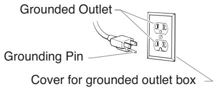
Grounding Instructions
This product must be grounded. In the event of an electrical short circuit, grounding reduces the risk of electric shock by providing an escape wire for the electric current. This product is equipped with a cord having a grounding wire with an appropriate grounding plug. The plug must be plugged into an outlet that is properly installed and grounded in accordance with all local codes and ordinances.
DANGER — Improper installation of the grounding plug can result in a risk of electric shock. If repair or replacement of the cord or plug is necessary, do not connect the green grounding wire to either flat blade terminal. The wire with insulation having a green outer surface with or without yellow stripes is the grounding wire and must be connected to the grounding pin.
Check with a qualified electrician or serviceman if the grounding instructions are not completely understood, or if you are in doubt as to whether the product is properly grounded. Do not modify the plug provided. If the plug will not fit the outlet, have the proper outlet installed by a qualified electrician.
CAUTION
Use only a 3-wire extension cord that has a 3-blade grounding plug and a 3-slot receptacle that will accept the plug on the product. Make sure your extension cord is in good condition. When using an extension cord, be sure to use one heavy enough to carry the current your product will draw. An undersized cord will cause a drop in line voltage resulting in loss of power and overheating. A 12 gauge cord is recommended. If an extension cord is to be used outdoors, it must be marked with the suffix W-A after the cord type designation. For example, a designation of SJTW-A would indicate that the cord would be appropriate for outdoor use.
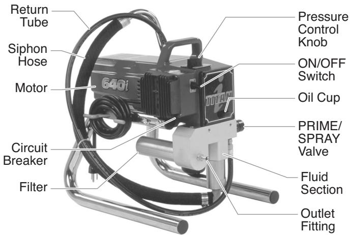
General Description
This airless sprayer is a precision power tool used for spraying many types of materials. Read and follow this instruction manual carefully for proper operating instructions, maintenance, and safety information.
Operation
WARNING
This equipment produces a fluid stream at extremely high pressure. Read and understand the warnings in the Safety Precautions section at the front of this manual before operating this equipment.
Setup
Perform the following procedure before plugging in the power cord of an electric unit.
- Ensure that the suction set/siphon tube and the return hose are attached and secure.
- Using a wrench, attach a minimum of 50^ of 1/4 ” nylon airless spray hose to the unit. Tighten securely.
- Attach an airless spray gun to the spray hose. Using two wrenches (one on the gun and one on the hose), tighten securely.
NOTE: Do not attach the tip to the spray gun yet. Remove the tip if it is already attached.
WARNING
Make sure all airless hoses and spray guns are electrically grounded and rated for at least 3200 psi (220 bar) fluid pressure.
- Make sure the pressure control knob is in its OFF position in the black zone.
- Make sure the ON/OFF switch is in its OFF position.
- Fill the oil cup with one tablespoon of piston seal lubricant (Piston Lube).
CAUTION
Never operate unit for more than ten seconds without fluid. Operating this unit without fluid will cause unnecessary wear to the packings.
- Make sure the electrical service is 120V, 15 amp minimum.
- Plug the power cord into a properly grounded outlet at least 25' from the spray area.
CAUTION
Always use a minimum 12 gauge, three-wire extension cord with a grounded plug. Never remove the third prong or use an adapter.
Preparing a New Sprayer
If this unit is new, it is shipped with test fluid in the fluid section to prevent corrosion during shipment and storage. This fluid must be thoroughly cleaned out of the system with mineral spirits before you begin spraying.
CAUTION
Always keep the trigger lock on the spray gun in the locked position while preparing the system.
- Place the suction tube into a container of mineral spirits that has a flash point of 140^ (60^) or above.
- Place the return hose into a metal waste container.
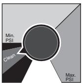
- Set the pressure to minimum by turning the pressure control knob to the "Min" setting in the yellow zone.
- Move the PRIME/SPRAY valve down to the PRIME position.
- Turn the unit on by moving the ON/OFF switch to the ON position.
- Allow the sprayer to run for 15-30 seconds to flush the test fluid out through the return hose and into the waste container.
- Turn the unit off by moving the ON/OFF switch to the OFF position.
Preparing to Paint
Before painting, it is important to make sure that the fluid in the system is compatible with the paint that is going to be used.
NOTE: Incompatible fluids and paint may cause the valves to become stuck closed, which would require disassembly and cleaning of the sprayer's fluid section.
CAUTION
Always keep the trigger lock on the spray gun in the locked position while preparing the system.
- Place the suction tube into a container of the appropriate solvent for the material being sprayed (refer to recommendations of the material manufacturer). An example of the appropriate solvent is water for latex paint.
-
Place the return hose into a metal waste container.
-
Set the pressure to minimum by turning the pressure control knob to the "Min" setting in the yellow zone.
- Move the PRIME/SPRAY valve down to the PRIME position.
- Turn the unit on by moving the ON/OFF switch to the ON position.
- Allow the sprayer to run for 15-30 seconds to flush the old solvent out through the return hose and into the metal waste container.
- Turn the unit off by moving the ON/OFF switch to the OFF position.
NOTE: Make sure that the spray gun does not have a tip or tip guard installed.
- Move the PRIME/SPRAY valve up to the SPRAY position.
- Turn the unit on.
- Unlock the gun by turning the gun trigger lock to the unlocked position.
WARNING
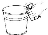
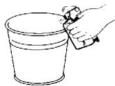
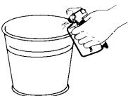
Ground the gun by holding it against the edge of the metal container while flushing. Failure to do so may lead to a static electric discharge, which may cause a fire.
- Trigger the gun into the metal waste container until the old solvent is gone and fresh solvent is coming out of the gun.
- Lock the gun by turning the gun trigger lock to the locked position.
- Set down the gun and increase the pressure by turning the pressure control knob slowly clockwise into the green zone.
- Check the entire system for leaks. If leaks occur, follow the "Pressure Relief Procedure" in this manual before tightening any fittings or hoses.
- Follow the "Pressure Relief Procedure" in this manual before changing from solvent to paint.
WARNING
Be sure to follow the pressure relief procedure when shutting the unit down for any purpose, including servicing or adjusting any part of the spray system, changing or cleaning spray tips, or preparing for cleanup.
Painting
- Place the suction tube into a container of paint.
- Place the return hose into a metal waste container.
- Set the pressure to minimum by turning the pressure control knob to the "Min" setting in the yellow zone.
- Move the PRIME/SPRAY valve down to the PRIME position.
- Turn the unit on by moving the ON/OFF switch to the ON position.
- Allow the sprayer to run until paint is coming through the return hose into the metal waste container.
- Turn the unit off by moving the ON/OFF switch to the OFF position.
- Remove the return hose from the waste container and place it in its operating position above the container of paint.
- Move the PRIME/SPRAY valve up to the SPRAY position.
- Turn the unit on.
- Unlock the gun by turning the gun trigger lock to the unlocked position.
WARNING
Ground the gun by holding it against the edge of the metal container while flushing. Failure to do so may lead to a static electric discharge, which may cause a fire.
- Trigger the gun into the metal waste container until all air and solvent is flushed from the spray hose and paint is flowing freely. from the gun.
- Lock the gun by turning the gun trigger lock to the locked position.
- Turn the unit off.
- Attach tip guard and tip to the gun as instructed by the tip guard or tip manuals.
Trigger lock in locked position.
WARNING
POSSIBLE INJECTION HAZARD. Do not spray without the tip guard in place. Never trigger the gun unless the tip is in either the spray or the unclog position. Always engage the gun trigger lock before removing, replacing or cleaning tip.
- Turn the unit on.
- Increase the pressure by turning the pressure control knob slowly clockwise toward the green zone and test the spray pattern on a piece of cardboard. Adjust the pressure control knob until the spray from the gun is completely atomized. Try to keep the pressure control knob at the lowest setting that maintains good atomization.
NOTE: Turning the pressure up higher then needed to atomize the paint will cause premature tip wear and additional overspray.
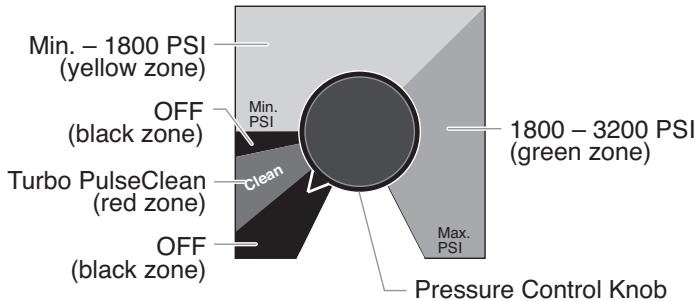
Electronic Pressure Control Indicators
The following is a description of the indicators on the electronic pressure control.
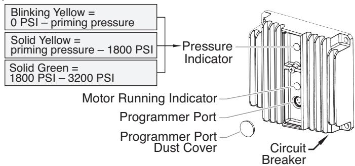
Pressure Indicator
The pressure indicator shows the current operating pressure of the sprayer. It has three different indications: blinking yellow, solid yellow, and solid green.
Blinking Yellow
When the pressure indicator is blinking yellow, the sprayer is operating between 0 and 200 PSI. A blinking yellow pressure indicator means:
- The sprayer is plugged in and turned "ON"
- The sprayer is at priming pressure (little or no pressure)
- It is safe to move the PRIME/SPRAY valve between positions
- It is safe to change or replace the spray tip (refer to gun manual for tip replacement instructions).
NOTE: If the pressure indicator begins blinking yellow when the pressure control knob is set at a higher pressure and the PRIME/SPRAY valve is in the SPRAY position, either the spray tip is worn, there is a leak, or the sprayer is in need of service/repair.
Solid Yellow
When the pressure indicator is solid yellow, the sprayer is operating between 200 and 1800 PSI. A solid yellow pressure indicator means:
- The sprayer is at the proper pressure setting for spraying stain, lacquer, varnish, and multi-colors
- If the pressure indicator goes to solid yellow when the pressure is set so that it starts at solid green, it indicates one of the following:
a. Tip Wear Indicator — when spraying with latex or at high pressure the solid yellow appears. This means the tip is worn and needs to be replaced.
b. Tip Too Large — when a tip that is too large for the sprayer is put in the gun, the pressure indicator will turn from solid green to solid yellow.
c. Fluid Section Wear — if a solid yellow pressure indicator appears when using a new tip and the pressure is set at maximum, service may be required (worn packings, worn piston, stuck valve, etc...).
Solid Green
When the pressure indicator is solid green, the sprayer is operating between 1800 and 3200 PSI. A solid green pressure indicator means:
- The sprayer is at the proper pressure setting for spraying oil-based and latex house paints
- The sprayer is operating at peak performance at a high pressure setting
Motor Running Indicator
The Motor Running indicator is on when the motor is commanded to run. This indicator is used by service centers to troubleshoot motor problems.
Pressure Relief Procedure
WARNING
Be sure to follow the pressure relief procedure when shutting the unit down for any purpose, including servicing or adjusting any part of the spray system, changing or cleaning spray tips, or preparing for cleanup.
- Lock the gun by turning the gun trigger lock to the locked position.
- Turn the unit off by moving the ON/OFF switch to the OFF position.
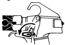
- Turn the pressure control knob counterclockwise to its OFF position in the black zone.
- Unlock the gun by turning the gun trigger lock to the unlocked position.
- Hold the metal part of the gun firmly to the side of a metal container to ground the gun and avoid a build up of static electricity.
- Trigger the gun to remove any pressure that may still be in the hose.
- Lock the gun by turning the gun trigger lock to the locked position.
- Move the PRIME/SPRAY valve down to the PRIME position.

Trigger lock in locked position.
Spraying
WARNING
POSSIBLE INJECTION HAZARD. Do not spray without the tip guard in place. Never trigger the gun unless the tip is in either the spray or the unclog position. Always engage the gun trigger lock before removing, replacing, or cleaning tip.
Spraying Technique
The following techniques, if followed, will assure professional painting results.
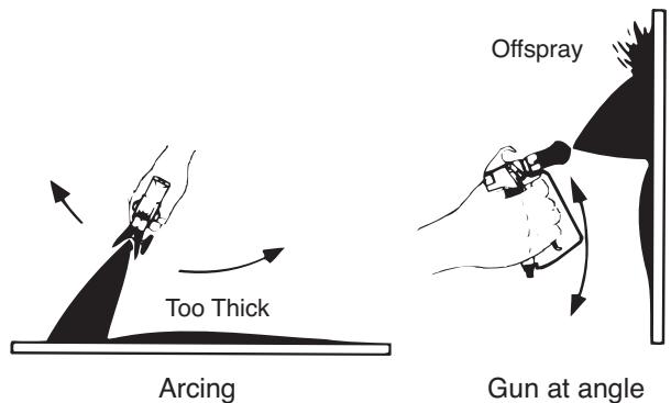
Hold the gun perpendicular to the surface and always at equal distance from the surface. Depending on the type of material, surface, or desired spray pattern, the gun should be held at a distance of 12 to 14 inches (30 to 35 cm).
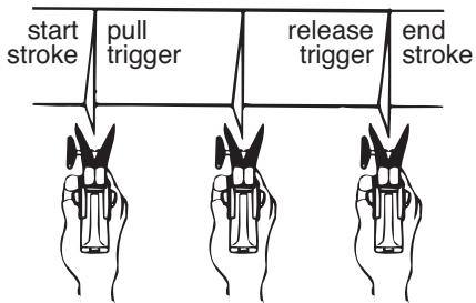
Move the gun either across or up and down the surface at a steady rate. Moving the gun at a consistent speed conserves material and provides even coverage. The correct spraying speed allows a full, wet coat of paint to be applied without runs or sags.
Holding the gun closer to the surface deposits more paint on the surface and produces a narrower spray pattern. Holding the gun farther from the surface produces a thinner coat and wider spray pattern. If runs, sags, or excessive paint occur, change to a spray tip with a smaller orifice. If there is an insufficient amount of paint on the surface or you desire to spray faster, a larger orifice tip should be selected.
Maintain uniform spray stroke action. Spray alternately from left to right and right to left. Begin movement of the gun before the trigger is pulled.
Avoid arcing or holding the gun at an angle. This will result in an uneven finish.
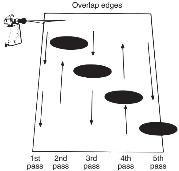
Proper lapping (overlap of spray pattern) is essential to an even finish. Lap each stroke. If you are spraying horizontally, aim at the bottom edge of the preceding stroke, so as to lap the previous pattern by 50% .
For corners and edges, split the center of the spray pattern on the corner or edge and spray vertically so that both adjoining sections receive approximately even amounts of paint.
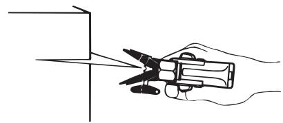
When spraying with a shield, hold it firmly against the surface. Angle the spray gun slightly away from the shield and toward the surface. This will prevent paint from being forced underneath.
Shrubs next to houses should be tied back and covered with a canvas cloth. The cloth should be removed as soon as possible. Titan gun extensions are extremely helpful in these situations.
Nearby objects such as automobiles, outdoor furniture, etc. should be moved or covered whenever in the vicinity of a spray job. Be careful of any other surrounding objects that could be damaged by overspray.
Practice
- Be sure that the paint hose is free of kinks and clear of objects with sharp cutting edges.
- Turn the pressure control knob counterclockwise to its to its lowest setting.
- Turn the PRIME/SPRAY valve up to its SPRAY position.
- Turn the pressure control knob clockwise to its highest setting. The paint hose should stiffen as paint begins to flow through it.
- Unlock the gun trigger lock.
- Trigger the spray gun to bleed air out of the hose.
-
When paint reaches the spray tip, spray a test area to check the spray pattern.
-
Use the lowest pressure setting necessary to get a good spray pattern. If the pressure is set too high, the spray pattern will be too light. If the pressure is set too low, tailing will appear or the paint will spatter out in gobs rather than in a fine spray.

Good spray pattern

Paint tailing pattern
Cleanup
WARNING
Special cleanup instructions for use with flammable solvents:
Always flush spray gun preferably outside and at least one hose length from spray pump.
- If collecting flushed solvents in a one gallon metal container, place it into an empty five gallon container, then flush solvents.
- Area must be free of flammable vapors.
- Follow all cleanup instructions.
CAUTION
The sprayer, hose, and gun should be cleaned thoroughly after daily use. Failure to do so permits material to build up, seriously affecting the performance of the unit.
WARNING
Always spray at minimum pressure with the gun nozzle tip removed when using mineral spirits or any other solvent to clean the sprayer, hose, or gun. Static electricity buildup may result in a fire or explosion in the presence of flammable vapors.
- Follow the "Pressure Relief Procedure" found in the Operation section of this manual.
- Remove the gun tip and tip guard and clean with a brush using the appropriate solvent.
- Place the suction tube into a container of the appropriate solvent (refer to recommendations of the material manufacturer). An example of the appropriate solvent is water for latex paint.
- Place the return hose into a metal waste container.
- Move the PRIME/SPRAY valve down to its PRIME position.
- Set the pressure to Turbo PulseClean by turning the pressure control knob to its CLEAN position in the red zone.
- Turn the unit on by moving the ON/OFF switch to the ON position.
- Allow the solvent to circulate through the unit and flush the paint out of the return hose into the metal waste container.
- Turn the unit off by moving the ON/OFF switch to the OFF position.
- Move the PRIME/SPRAY valve up to its SPRAY position.
- Turn the unit on.
WARNING
Ground the gun by holding it against the edge of the metal container while flushing. Failure to do so may lead to a static electric discharge, which may cause a fire.
- Trigger the gun into the metal waste container until the paint is flushed out of the hose and solvent is coming out of the gun.
- Continue to trigger the spray gun into the waste container until the solvent coming out of the gun is clean.
NOTE: For long-term or cold weather storage, pump mineral sprits through the entire system. For short-term storage when using latex paint, pump water mixed with Titan Liquid Shield through the entire system (see the Accessories section of this manual for part number).
- Follow the "Pressure Relief Procedure" found in the Operation section of this manual.
- Unplug the unit and store in a clean, dry area.
CAUTION
Do not store the unit under pressure.
Maintenance
WARNING
Before proceeding, follow the Pressure Relief Procedure outlined previously in this manual. Additionally, follow all other warnings to reduce the risk of an injection injury, injury from moving parts or electric shock. Always unplug the sprayer before servicing!
General Repair and Service Notes
The following tools are needed when repairing this sprayer:
Phillips Screwdriver 3/8" Hex Wrench
Needle Nose Pliers 5/16" Hex Wrench
Adjustable Wrench 1/4" Hex Wrench
Rubber Mallet 3/16" Hex Wrench
Flat-blade Screwdriver 5/32" Hex Wrench
- Before repairing any part of the sprayer, read the instructions carefully, including all warnings.
CAUTION
Never pull on a wire to disconnect it. Pulling on a wire could loosen the connector from the wire.
- Test your repair before regular operation of the sprayer to be sure that the problem is corrected. If the sprayer does not operate properly, review the repair procedure to determine if everything was done correctly. Refer to the Troubleshooting Charts to help identify other possible problems.
-
Make certain that the service area is well ventilated in case solvents are used during cleaning. Always wear protective eyewear while servicing. Additional protective equipment may be required depending on the type of cleaning solvent. Always contact the supplier of solvents for recommendations.
-
If you have any further questions concerning your TITAN Airless Sprayer, call TITAN:
Customer Service (U.S.) 1-800-526-5362
Fax 1-800-528-4826
Customer Service (Canada) 1-800-565-8665
Fax 1-905-856-8496
Customer Service (International) 1-201-337-1240
Fax 1-201-405-7449
Replacing the Motor
- Unplug the unit.
- Loosen and remove the four motor cover screws. Remove the motor cover.
- Disconnect the black and red wires coming from the pump housing. Disconnect the black and red wires from the capacitors. Disconnect the black and red wires from the motor.
- Remove the capacitors from their mounting clip.
- Loosen and remove the four motor mounting screws.
- Pull the motor out of the pump housing.
NOTE: If the motor will not dislodge from the pump housing:
- Remove the front cover plate.
-
Using a rubber mallet, carefully tap on the front of the motor crankshaft that extends through the connecting rod.
-
With the motor removed, inspect the gears in the pump housing for damage or excessive wear. Replace the gears, if necessary.
- Install the new motor into the pump housing.
NOTE: Rotate the motor fan manually until the armature gear engages with the mating gear in the pump housing.
- Secure the motor with the four motor mounting screws.
- Push the capacitors into their clip on the new motor.
- Reconnect the wires (refer to the electrical schematic in the Parts List section of this manual).
- Slide the motor cover over the motor. Secure the motor cover with the four motor cover screws.
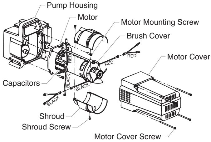
Replacing the Motor Brushes
Perform this procedure using Motor Brush Kit P/N 704-276.
- Loosen and remove the four motor cover screws. Remove the motor cover.
- Loosen and remove the two shroud screws. Remove the shroud.
- Using a small screwdriver, pry off the two plastic brush covers.
- Disconnect the black and red wires from the motor brushes. Remove the motor brushes.
- Install the new motor brushes and snap on the plastic brush covers.
- Reconnect the black and red wires from the motor brushes (refer to the electrical schematic in the Parts List section of this manual).
- Position the shroud over the motor fan. Secure the shroud with the two shroud screws.
- Slide the motor cover over the motor. Secure the motor cover with the four motor cover screws.
Replacing the Gears
- Loosen and remove the four motor cover screws. Remove the motor cover.
- Disconnect the black and red wires coming from the pump housing.
- Loosen and remove the four motor mounting screws.
- Pull the motor out of the pump housing.
NOTE: If the motor will not dislodge from the pump housing:
- Remove the front cover plate.
-
Using a rubber mallet, carefully tap on the front of the motor crankshaft that extends through the connecting rod.
-
Inspect the armature gear on the end of the motor for damage or excessive wear. If this gear is completely worn out, replace the entire motor.
- Remove and inspect the 2nd stage gear for damage or excessive wear. Replace if necessary.
- Remove and inspect the gear and crank assembly for damage or excessive wear. Replace if necessary.
- Reassemble the pump by reversing the above steps. During reassembly, make sure the thrust washers is in place.
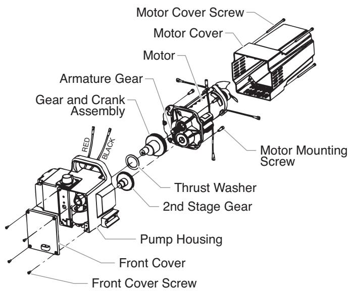
NOTE: Refill the gear box with five ounces of Lubriplate (P/N 314-171).
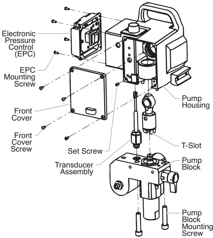
Replacing the Transducer
- Loosen and remove the four front cover screws. Remove the front cover.
- Stop the sprayer at the bottom of its stroke so that the piston is in its lowest position. Turn off and unplug the sprayer.
WARNING
Before proceeding, follow the Pressure Relief Procedure outlined previously in this manual. Additionally, follow all other warnings to reduce the risk of an injection injury, injury from moving parts or electric shock. Always unplug the sprayer before servicing!
- Tilt the pump back for easy access to the fluid section.
- Using a 3/8 hex wrench, loosen and remove the two pump block mounting screws.
- Pull the pump block down approximately 1/2 from the pump housing to clear the transducer.
- Slide the pump block and piston rod forward until the piston rod is out of the T-slot on the connecting rod.
- Loosen and remove the four electronic pressure control (EPC) mounting screws.
- Pull back the EPC for access to the transducer plug-in.
- Unplug the transducer connection from EPC board location "JP3" (refer to the electrical schematic in the Parts List section of this manual).
- Using an 1/8 hex wrench, loosen and remove the set screw from the bottom of the pump housing.
- Slide the transducer assembly out of the bottom of the pump housing.
- Install the new transducer assembly into the pump housing.
- Thread the set screw into the pump housing and tighten securely.
- Plug the transducer connection into the EPC board at location "JP3" (refer to the electrical schematic in the Parts List section of this manual).
- Reassemble the pump by reversing steps 1-8.
CAUTION
Make sure the transducer is aligned properly with the hole in the pump block during reassembly. Improper alignment may cause damage to the transducer gasket.
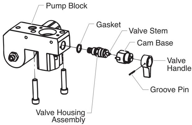
Replacing the PRIME/SPRAY Valve
Perform the following procedure using PRIME/SPRAY valve replacement kit P/N 700-258.
- Push the groove pin out of the valve handle.
- Remove the valve handle and the cam base.
- Using a wrench, loosen and remove the valve housing assembly.
- Make sure the gasket is in place and thread the new valve housing assembly into the pump block. Tighten securely with wrench.
- Place the cam base over the valve housing assembly. Lubricate the cam base with grease and line up the cam with the pump block.
- Line up the hole on the valve stem with the hole in the valve handle.
- Insert the groove pin into the valve handle and through the valve stem to secure the valve handle in position.
Servicing the Fluid Section
Use the following procedures to service the valves and repack the fluid section. Perform the following steps before performing any maintenance on the fluid section.
- Loosen and remove the four front cover screws. Remove the front cover.
- Stop the sprayer at the bottom of its stroke so that the piston is in its lowest position. Turn off and unplug the sprayer.
WARNING
Before proceeding, follow the Pressure Relief Procedure outlined previously in this manual. Additionally, follow all other warnings to reduce the risk of an injection injury, injury from moving parts or electric shock. Always unplug the sprayer before servicing!
- Unscrew the return hose assembly from the pump block.
- Remove the retaining clip that holds the suction set in the foot valve. Pull the suction set out of the foot valve.
- Tilt the pump back for easy access to the fluid section.
Servicing the Valves
The design of Titan's fluid section allows access to the foot valve and seat as well as the outlet valve and seat without completely disassembling the fluid section. It is possible that the valves may not seat properly because of debris stuck in the foot valve seat or outlet valve seat. Use the following instructions to clean the valves and reverse or replace the seats.
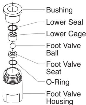
- Using a wrench, loosen and remove the foot valve housing from the pump block.
- Clean out any debris in the foot valve housing and examine the valve housing and seat. If the seat is damaged, reverse or replace the seat.
- Using a 3/8'' hex wrench, loosen and remove the outlet valve housing from the piston rod.
NOTE: Always service the outlet valve with the piston rod attached to the pump. This will prevent the piston rod from rotating during disassembly of the outlet valve.
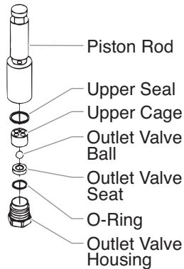
- Clean out any debris and examine the valve housing and seat. If the seat is damaged, reverse or replace the seat.
- Remove, clean, and inspect the housing upper cage and upper ball. Replace if they are worn or damaged.
- Reassemble the valves by reversing the steps above.
Repacking the Fluid Section
NOTE: The factory-installed packings are black in color. The replacement packings in the packing replacement kit are white.
- Remove the foot valve and outlet valve assemblies using the steps in the "Servicing the Valves" procedure above.
- Using 3 / 8 a hex wrench, loosen and remove the two pump block mounting screws.
- Pull the pump block down approximately 1 / 2 from the pump housing.
- Slide the pump block and piston rod forward until the piston rod is out of the T-slot on the connecting rod.
- Slide the piston rod out through the bottom of the pump block
- Loosen and remove the retainer nut and piston guide from the pump block.
- Remove the upper and lower packings from the pump block.
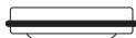
- Clean the pump block and install the new upper and lower packings. Refer to the illustration below for proper packing orientation.
Install upper packing with raised lip and O-ring facing down.
Install lower packings with raised lip and O-ring facing up.

O-Ring
Raised Lip
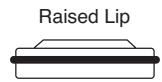
O-Ring

- Inspect the piston rod for wear and replace if necessary.
- Reassemble the outlet valve assembly into the piston rod. Tighten the outlet valve housing with a wrench until secure.
NOTE: Use the T-slot on the connecting rod to hold the piston rod in position while securing the outlet valve housing.
CAUTION
Never use a wrench on the piston itself. This could cause damage to the piston and cause leakage.
- Insert the piston guide into the retainer nut. Thread the retainer nut into the pump block until it is hand tight.
- Slide the piston guide tool (included in the repacking kit) over the top of the piston rod and insert the piston rod through the bottom of the pump block. Using a rubber mallet, tap the bottom of the piston rod lightly until the piston rod is in position in the pump block.
NOTE: Coat the piston guide tool and the piston rod with grease before inserting them into the pump block.
- Using a wrench, tighten the retainer nut securely.
- Slide the top of the piston rod into the T-slot on the connecting rod.
- Position the pump block underneath the pump housing and push up until it rests against the pump housing.
CAUTION
Make sure the transducer is aligned properly with the hole in the pump block during reassembly. Improper alignment may cause damage to the transducer gasket.
- Thread the pump block mounting screws through the pump block and into the pump housing. Tighten securely.
- Reassemble the foot valve assembly into the pump block.
- Insert the elbow on the suction set into the bottom of the foot valve. Position the retaining clip into the foot valve to secure the suction set assembly.
- Thread the return hose into the pump block and tighten securely.
- Place the front cover on the pump housing and secure in position using the four front cover screws.
- Turn on the sprayer by following the procedure in the "Operation" section of this manual and check for leaks.
NOTE: Repacking kit P/N 730-401 is available. For best results use all parts supplied in this kit.
Replacing the Filters
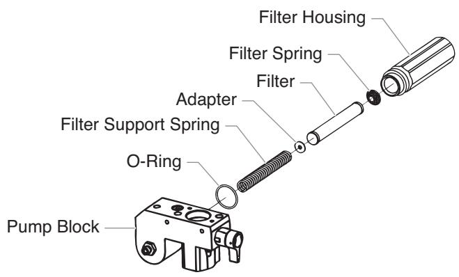
Pump Filter
- Loosen and remove the filter housing by hand.
- Slip the filter off of the filter support spring.
- Inspect the filter. Based on inspection, clean or replace the filter.
- Inspect the o-ring. Based on inspection, clean or replace the o-ring.
- Slide the new or cleaned filter over the filter support spring with the adapter in place. Push the filter into the center of the pump block.
- Slide the filter housing over the filter and thread it into the pump block until secure.
NOTE: The filter housing should be hand-tightened, but make sure the filter housing is seated fully into the pump block.
Gun Filter
- Move the gun trigger lock to the unlocked position.
- Loosen and remove the handle from the gun head.
- Turning clockwise, unscrew the filter from the gun head.
NOTE: Left-handed threads require turning the filter clockwise to remove.
- Turning counterclockwise, screw the new or cleaned filter into the gun head.
- Make sure the handle seal is in position and thread the handle into the gun head until secure.
- Move the gun trigger lock to the locked position.
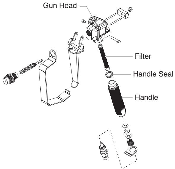
NOTE: For more detail, part number information, and assembly drawings at larger scale, please see the LX-80 II Professional Airless Gun Owner's Manual (P/N 313-2069).
Troubleshooting
Problem
The unit will not run.
The unit will not prime.
The unit will not build or maintain pressure.
Fluid leakage at the upper end of the fluid section.
Cause
- The unit is not plugged in.
- Tripped breaker.
- The pressure is set too low (pressure control knob set at minimum setting does not supply power to unit).
- Faulty or loose wiring.
- Excessive motor temperature.
- ON/OFF switch is defective.
- The PRIME/SPRAY valve is in the SPRAY position.
- Air leak in the siphon tube/suction set.
- The pump filter and/or inlet screen is clogged.
- The siphon tube/suction set is clogged.
- The spray tip is worn.
- The spray tip is too large.
- The pressure control knob is not set properly.
- The pump filter, gun filter, or inlet screen is clogged.
- Material flows from the return hose when the PRIME/SPRAY valve is in the SPRAY position.
- Air leak in the siphon tube/suction set.
- There is external fluid leak.
- There is an internal fluid section leak (packings are worn and/or dirty, valve balls are worn).
- Worn valve seats
- Motor powers but fails to rotate
- The upper packings are worn.
- The piston rod is worn.
Solution
- Plug the unit in.
- Reset the breaker.
- Turn the pressure control knob clockwise to supply power to the unit and increase the pressure setting.
- Inspector or take to a Titan authorized service center.
- Allow motor to cool.
-
Replace the ON/OFF switch.
-
Rotate the PRIME/SPRAY valve clockwise to the PRIME position.
- Check the siphon tube/suction set connection and tighten or re-tape the connection with Teflon tape.
- Remove the pump filter element and clean. Remove the inlet screen and clean.
-
Remove the siphon tube/suction set and clean.
-
Replace the spray tip following the instructions that came with the spray gun.
- Replace the spray tip with a tip that has a smaller orifice following the instructions that came with the spray gun.
- Turn the pressure control knob clockwise to increase the pressure setting.
- Remove the pump filter element and clean. Remove the gun filter and clean. Remove the inlet screen and clean.
- Clean or replace the PRIME/SPRAY valve.
- Check the siphon tube/suction set connection and tighten or re-tape the connection with Teflon tape.
- Check for external leaks at all connections. Tighten connections, if necessary.
- Clean the valves and service the fluid section following the "Servicing the Fluid Section" procedure in the Maintenance section of this manual.
- Reverse or replace the valve seats following the "Servicing the Fluid Section" procedure in the Maintenance section of this manual.
- Take unit to a Titan authorized service center.
- Repack the pump following the "Servicing the Fluid Section" procedure in the Maintenance section of this manual.
- Replace the piston rod following the "Servicing the Fluid Section" procedure in the Maintenance section of this manual.
Troubleshooting
Problem
Excessive surge at the spray gun.
Cause
- Wrong type of airless spray hose.
- The spray tip worn or too large.
- Excessive pressure.
Poor spray pattern.
- The spray tip is too large for the material being used.
- Incorrect pressure setting.
- Insufficient fluid delivery.
- The material being sprayed is too viscous.
The unit lacks power.
- The pressure adjustment is too low.
- Improper voltage supply.
Solution
- Replace hose with a minimum of 50' of 1/4" grounded textile braid airless paint spray hose.
- Replace the spray tip following the instructions that came with the spray gun.
-
Rotate the pressure control knob counterclockwise to decrease spray pressure.
-
Replace the spray tip with a new or smaller spray tip following the instructions that came with the spray gun.
- Rotate the pressure control knob to adjust the pressure for a proper spray pattern.
- Clean all screens and filters.
-
Add solvent to the material according to the manufacturer's recommendations.
-
Rotate the pressure control knob clockwise to increase the pressure setting.
- Reconnect the input voltage for 120V AC.
Warranty
Titan Tool, Inc., "Titan") warrants that at the time of delivery to the original purchaser for use ("End User"), the equipment covered by this warranty is free from defects in material and workmanship. Titan's obligation under this warranty is limited to replacing or repairing without charge those parts which, to Titan's reasonable satisfaction, are shown to be defective within twenty-five (25) months after sale to the End User. This warranty applies only when the unit is installed and operated in accordance with the recommendations and instructions of Titan.
This warranty does not apply in the case of damage or wear caused by abrasion, corrosion or misuse, negligence, accident, faulty installation, substitution of non-Titan component parts, or tampering with the unit in a manner to impair normal operation.
Defective parts are to be returned to an authorized Titan sales/service outlet. All transportation charges, including return to the factory, if necessary, are to be borne and prepaid by the End User. Repaired or replaced equipment will be returned to the End User transportation prepaid.
THERE IS NO OTHER EXPRESS WARRANTY. TITAN HEREBY DISCLAIMS ANY AND ALL IMPLIED WARRANTYES INCLUDING, BUT NOT LIMITED TO, THOSE OF MERCHANTABILITY AND FITNESS FOR A PARTICULAR PURPOSE, TO THE EXTENT PERMITTED BY LAW. THE DURATION OF ANY IMPLIED WARRANTYES WHICH CANNOT BE DISCLAIMED IS LIMITED TO THE TIME PERIOD SPECIFIED IN THE EXPRESS WARRANTY. IN NO CASE SHALL TITAN LIABILITY EXCEED THE AMOUNT OF THE PURCHASE PRICE. LIABILITY FOR CONSEQUENTIAL, INCIDENTAL OR SPECIAL DAMAGES UNDER ANY AND ALL WARRANTYES IS EXCLUDING TO THE EXTENT PERMITTED BY LAW.
TITAN MAKES NO WARRANTY AND DISCLAIMS ALL IMPLIED WARRANTY OF MERCHANTABILITY AND FITNESS FOR A PARTICULAR PURPOSE WITH RESPECT TO ACCESSORIES, EQUIPMENT, MATERIALS OR COMPONENTS SOLD BUT NOT MANUFACTURED BY TITAN. THOSE ITEMS SOLD, BUT NOT MANUFACTURED BY TITAN (SUCH AS GAS ENGINES, SWITCHES, HOSES, ETC.) ARE SUBJECT TO THE WARRANTY, IF ANY, OF THEIR MANUFACTURER. TITAN WILL PROVIDE THE PURCHASER WITH REASONABLE ASSISTANCE IN MAKING ANY CLAIM FOR BREACH OF THESE WARRANTY.
Patents
These products are covered by one or more of the following U.S. patents:
4,500,119 4,768,929
Material Safety Data Sheets (MSDS) are available on Titan's website or by calling Customer Service.
Table des matières
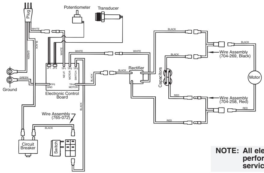
NOTE: All electrical work should be performed by an authorized service center.
Install upper packing with raised lip and O-ring facing down.
Raised Lip
O-Ring
NOTE: Packing kit P/N 730-401 includes those items marked with an *. Also included are packing grease P/N 700-203 and piston guide tool P/N 700-793.
| Item | Part # | Description | Quantity |
| 1 | 704-263 | Return tube assembly. | 1 |
| 2 | 704-121 | O-ring. | 2 |
| 704-109 | O-ring (for hot solvents, optional) | ||
| 3 | 700-1024 | Elbow. | 1 |
| 4 | 704-127 | Retaining clip. | 1 |
| 5 | 700-1023 | Siphon hose (includes items 2-4, and 7). | 1 |
| 6 | 755-135 | Clip. | 1 |
| 7 | 700-805 | Inlet screen. | 1 |
Français
Tips are selected by the orifice size and fan width. The proper selection is determined by the fan width required for a specific job and by the orifice size that will supply the desired amount of fluid and accomplish proper atomization.
For light viscosity fluids, smaller orifice tips generally are desired. For heavier viscosity materials, larger orifice tips are preferred. Please refer to the chart below.
NOTE: Do not exceed the sprayer's recommended tip size.
The following chart indicates the most common sizes and the appropriate materials to be sprayed.
| Tip Size | Spray Material | Filter Type |
| .011 – .013 | Lacquers and stains | 100 mesh filter |
| .015 – .019 | Oil and latex | 60 mesh filter |
| .021 – .026 | Heavy bodied latex and blockfillers | 30 mesh filter |
Fan widths measuring 8" to 12" (20 to 30 cm) are preferred because they offer more control while spraying and are less likely to plug.
Liquid Shield Plus
Cleans and protects spray systems against rust, corrosion and premature wear. Now with -25^ anti-freeze protection.
Part #
314-483
Description
314-482
.....4 ounce bottle
.....1 quart bottle
Piston Lube
Specially formulated to prevent materials from adhering to the piston rod, which becomes abrasive to the upper seals. Piston Lube will break down any material that may accumulate in the oil cup and keep it from drying.
Part # Description
314-481............4 ounce bottle
314-480. 8 ounce bottle
Miscellaneous
Part No.
Description
490-012......Hose Coupling, 1/4" x 1/4"
730-397......High Pressure Fl. Gauge
314-171.......Lubriplate, 14 ounce individual
314-172.......Lubriplate, 6 lb. can
700-1037.....Electrostatic discharge (ESD) wrist strap
Accessoires
NOTE: All electrical work should be performed by an authorized service center.
Français
Weight, skid. 35 lbs. (15.9kg)
Weight, high/low rider.....55 lbs. (25.9kg)
Capacity .Up to .57 gallons/min.(2.2 liters/min.)
Power source 1.3 hp DC motor
Power requirement.....15 amp minimum circuit on 115
VAC, 60 Hz current.
Spraying pressure.......Up to 3200 psi/221 bar
Max. tip size .0.023
Max. hose length. 300 ft. (91.4m)
Max. power cord length....300 ft. (91.4m)
Spécifications
Poids, support 35 lbs. (15,9kg)
Poids, chariot/
basse chariot. 55 lbs. (25,9kg)
Airless Spray Technology

United States Sales & Service
1-800-526-5362
Fax 1-800-528-4826
107 Bauer Drive
Oakland, NJ 07436
www.titantool.com
Canadian Branch
1-800-565-8665
Fax 1-905-856-8496
200 Trowers Road, Unit 7B
Woodbridge, Ontario L4L 5Z8
International
1-201-337-1240
Fax 1-201-405-7449
107 Bauer Drive
Oakland, NJ 07436 USA