
BE7II - Motherboard ABIT - Free user manual and instructions
Find the device manual for free BE7II ABIT in PDF.

| Product Type | Motherboard for desktop computer |
| Brand | ABIT |
| Model | BE7II |
| CPU Socket | Socket 478 for Intel Pentium 4 |
| Chipset | Intel 845E |
| Memory Type | DDR SDRAM, 2 DIMM slots, max 2 GB |
| Expansion Slots | 1 AGP 4x slot, 5 PCI slots |
| Storage Connectors | 2 IDE connectors, 1 FDD connector |
| USB Connectors | 4 USB 2.0 ports (2 rear, 2 via header) |
| Integrated Audio | AC'97 with headphone, microphone and line-in jacks |
| Network | Integrated 10/100 Mbps Ethernet controller |
| Dimensions (Form Factor) | Standard ATX, 305 mm x 244 mm |
| Net Weight | Approximately 0.8 kg |
| Power Requirement | 20-pin ATX connector and 4-pin ATX12V connector |
| Key Features | Supports Pentium 4, AGP 4x, USB 2.0, integrated audio and network |
| Maintenance and Cleaning | Use a dry, lint-free cloth; avoid any liquid |
| Safety | Discharge static electricity before handling |
| Spare Parts and Repairability | CPU heatsink, fan, IDE cables and FDD cable included |
Frequently Asked Questions - BE7II ABIT
User questions about BE7II ABIT
0 question about this device. Answer the ones you know or ask your own.
Ask a new question about this device
Download the instructions for your Motherboard in PDF format for free! Find your manual BE7II - ABIT and take your electronic device back in hand. On this page are published all the documents necessary for the use of your device. BE7II by ABIT.
USER MANUAL BE7II ABIT
Socket 478 System Board User's Manual
Copyright and Warranty Notice
The information in this document is subject to change without notice and does not represent a commitment on part of the vendor, who assumes no liability or responsibility for any errors that may appear in this manual.
No warranty or representation, either expressed or implied, is made with respect to the quality, accuracy or fitness for any particular part of this document. In no event shall the manufacturer be liable for direct, indirect, special, incidental or consequential damages arising from any defect or error in this manual or product.
Product names appearing in this manual are for identification purpose only and trademarks and product names or brand names appearing in this document are the property of their respective owners.
This document contains materials protected under International Copyright Laws. All rights reserved. No part of this manual may be reproduced, transmitted or transcribed without the expressed written permission of the manufacturer and authors of this manual.
If you do not properly set the motherboard settings, causing the motherboard to malfunction or fail, we cannot guarantee any responsibility.
Table Of Contents
快速安装指引 1
Kiyuckinnsut-ullgaiid 3
KpaTkoe pyKOBoCTBO IIO ycTaHOBKe 9
Chapter 2. Hardware Setup 2-1
2-1. Install The Motherboard.. 2-1
2-2. Install Pentium® 4 CPU and Heatsink Supporting-Base. 2-2
2-3. Install System Memory 2-3
2-4. Connectors, Headers and Switches 2-4
(1).ATX Power Input Connectors. 2-4
(2). FAN Connectors. 2-5
(3). CMOS Memory Clearing Header 2-6
(4). Front Panel Audio Connection Header 2-7
(5). Front Panel Switches & Indicators Headers 2-8
(6). Additional USB Port Headers 2-9
(7). System Management Bus Headers. 2-10
(8). Internal Audio Connectors 2-10
(9). Accelerated Graphics Port Slot 2-11
(10). Status Indicators. 2-11
(11). Floppy Disk Drive Connector. 2-12
(12). IDE Connectors. 2-13
(13). Back Panel Connectors 2-14
Chapter 3. BIOS Setup 3-1
3-1. SoftMenu Setup.. 3-2
3-2. Standard CMOS Features.. 3-4
3-3. Advanced BIOS Features 3-7
3-4. Advanced Chipset Features 3-9
3-5. Integrated Peripherals 3-11
3-6. Power Management Setup 3-15
3-7. PnP/PCI Configurations 3-17
3-8. PC Health Status 3-19
3-9. Load Fail-Safe Defaults 3-20
3-10. Load Optimized Defaults.. 3-20
3-11. Set Password 3-20
3-12. Save & Exit Setup 3-20
3-13. Exit Without Saving 3-20
Appendix A. Install Intel Chipset Software Utility.. 4-1
Appendix B. Install Intel Application Accelerator.. 2
Appendix C. Install Audio Driver..
Appendix D. Install LAN Driver.... .D-1
Appendix E. Install USB 2.0 Driver..
Appendix F. ABIT EQ (The Hardware Doctor Utility)
Appendix G. Troubleshooting (Need Assistance?) 1
Appendix H. How to Get Technical Support..
快速安装指引
- HaJIHTe Ha cHCTeMHoI IJIaTe 478-BbIBOJHOI pa3bEm TIIa ZIF. 3aKpeINTe OCHOBaHHe paHaTopa Ha cHCTeMHoI IJIaTe.
BHHMaHHe: YcTaHaBJIHbAa IIaTy B KOpIYc, pa3pa6oTaAHbI cIIeuaJIbHO IJIa Pentium 4, o6paTHTe BHHMaHHe Ha yJke yCTaHOBJeHNbI KpeIeK (MeTaJIInueCKHe cToKN, 3aJHMbI). Y6eINTEcb, YTO yCTaHOBJeHNbI KpeIeK He Kacaetcsc nCTeMHo IIJIaTbI HII ee BBIOOB.
- OTTHHTe pbyar fHKcaHHIpoeeccopa B CTPOHY HIOHNHMTe ero Ha 90 rpaYcoB BBepx. PaioJIOXHBIpoeeccop COOTBETCTBYIOHM O6pa3OM, BCTaBBte ero B pa3bEm. He IprHaarite H3JIHHHX yCHIN, YTO6bI BCTaBBtB Ipoeeccop. IIpoeeccop JeTKO yCTaHABIIHBAeTcA, cEiIN Bbl IpaBHbHO cOBMeCTHIN ero C pa3bEMOM. YCTaHOBBIpoeeccop ONyCTHHe pbyar fHKcaHHIpoeeccopa Ha MeTo.
3.Плжнту на поцesscop радатор tak,чтобу onпліноctьн haкрьвал поцesscop.
4.ПлJOKHTe Ha paДHATop BeHTHJIATOp H ФнКсчpyIOIIH mexaHn3M. Y6eIITecb, YTO BCE ЧeТыpe ФнКсATopa BeHTHJIATOpa H ФнКсчpyIOIIeFO mexaHn3Ma BOIIJIN B ПпeДиAЗHAчЕHьIE OTBepCTHЯ 3aIIeJIKNHJIHCb. - 3aΦHKChpyTe BeHTHJIArTop Ha OCHOBAHn paHaTopa, onYCTHB pbuKaKh, paCIOJOKeHHbIe c o6eHX cTOpOH φHKChpyIOJIero mexAHN3Ma.
- BeHTHJIaTOp, ΦHKcHpyUOIIH mExaHH3m H oChOBaHHe paJHaTopa JIoJKHbI 6bITb HaJeKHO 3aKpeJIeHb BMeCTe C BeHTHJIaTOpom.
BHHMaHHe: YcTaHOBHTe COOTBeTCTByIOIIne HaCTOTy H KpaTHOcTB IIHHbI IpoIeccopa.
YcTaHOBKa MaTePHHCKo IIJaTbI B KopIIvC
IocJe yctAHOBKN IpoIeCCopa Ha MaTePHHcKyo IJIaTy MOKHO HauHHaTHy cTaHOBKy MaTePHHcKOI IJIaTbB KOpIyc. BoJIbIIaA qacTh B KopIycob O6OpYIOBaHa OCHOBaHHem, B KOToPOM IpoJdeJaHbMOHTaXHBe OTBepCTHn, KOTOpbIE IO3BOJIaHOT HaIdekHO 3aKpeINITb MaTePHHcKyo IJIaTy H IpEIoTbPaHTbKOpOTKHe 3aMbKaHHa.ДЯ KpeIJIeHHaMaTePHHcKo IJIaTbK OCHOBaHHIO HcIOJIb3yOTcB BHTbI HIpOKlaIKn.
UcTaHOBKa MoVJeIaMaTn
- HaJIHTe Ha cHCTeMHoH IJIaTe pa3bEm JIIM MOyJIeI IIAMrTH DIMM.
- AkkypaTHO, 3a Два KOHua, BO3bMHTe MOdYJIb IIamTn, He KaCaaCb KOHTaKTOB.
- CoBmecTHTe BbIeMky B MoIyJIe IaMaTHn C BbICTYIOB Bpa3bEme.
- HaKMHTe Ha MOyJb TaK, YTO6bI JeIeCTKN BbITaIKHBateJIc o6eHX cTOpOH pa3BeMa
aBTOMaTHUeCKH 3aIeJIKNJINb H BOIIIN B Ia3bl. He IIpHMEnHrTe IIpn yCTaHOBKe H3JIINIIIHOIO cHJy. MoYJb BXoINT B pa3bEm TOJIbKO B OIDHom IOJOXKeHH.
5.ДИЯ H3BJIeueHЯ MOnIyIeI IaMЯTH DIMM OdHOBpeMeHHO HaKMHTe Ha JIeIeCTKN BbITaIKHBaTeJIA N BbITaIIHTe MoIyJIb.
BHHMaHHe: CtaTHueckoe 3JIeKTPnuecTBO MOKeT cTaTb IIpNHyHOI BbIXoHa H3 cTpOa 3JIeKTPoHHbIX KOMIIHOHTOB KOMIIbIOTepa. IpeE HaayAIOM DaHHO IIpoUeDpybI ChHMITE c ce6a cTaTHueCKHI 3apJ,I KCHyBIIIcB 3a3eMJIeHHOro MeTAJIINueckOTo IIpeDMeta.
Pa3bEmbl, HepeKJIIOuATEHn H aIaIITepbl
BHytpn Koprnyca KOMIIbIOTepa Heo6xOJHMO pacIOJIooKeHb HecKOJIbKO Ka6eJIe N BHNIOK, KOtOpBle Heo6xOJHMO IOIKIIOUHTb. O6bIyHO 3TH Ka6eJIIN IOKJIIOUHaOTcK pa3bEmAM, pacIOJIIOKeHHbIM Ha MaTePHNCKO IIATE. PPh IOKJIIOUeHHN IIO6Oro Ka6eJIa Heo6xOJHMO o6paIaTb BHNMaHHe Ha pacIOJIIOKeHHe IEPBOrO KOHTAKTa pa3bema.ДЯ OOC6bIX IeJIe MOrYT IOTpe6OBaTcBc CIEIIaJIbHBe aADITepb, HapnMep, aadITep SCSI, aadITep AGP n T.I.. PPh yCTaHOBke aadITepOB B rHe3Ja MaTePHNCKO IIATb 3akpeINrte Hx Ha 3aIDNe IaHEJIc NOMOIIbBO BVHTOB.
3a 6oJIee IIOJIO6HOn HnΦopMaIeH O6paIaItec b K IOJIHOmy pyKOBOCTBy IOJIb3OBATeJIa.
1-1. Features & Specifications
1. CPU
Supports Intel Pentium 4/Celeron Socket 478 processors (Northwood P4, Celeron 2G and higher) with 533MHz / 400MHz FSB
Supports Intel Hyper-Threading Technology
2. Chipset
Intel 82845PE (MCH) + 82801DB (ICH4)
Supports Universal Serial Bus (USB 2.0)
3. Memory
- Two 184-pin DDR DIMM sockets (un-buffered Non-ECC DIMM)
Supports 2 DIMM DDR 333/266/200 (Max. 2GB)
4. Audio
AC'97 6-channel Audio CODEC onboard
5. LAN
Onboard 10/100M PCI Ethernet Controller
6. Internal I/O Connectors
1x AGP slot
- 5x PCI slots
1x Floppy port supports up to 2.88MB
2x Ultra ATA 100/66/33 connectors
- 2x USB 2.0 headers
1x FP-AUDIO header
1x CD-IN, 1x AUX-IN header
7. Back Panel I/O
1x PS/2 Keyboard, 1x PS/2 mouse
1x Serial port connector, 1x Parallel port connector
1x Audio connector (Line-out, Line-in, Mic-in)
- 2x USB connectors, 1x RJ-45 LAN connector
8. Miscellaneous
ATX form factor (305mm× 190mm)
- Hardware Monitoring - including Fan Speed, Voltages, CPU and system temperature
Supports Wake Up by LAN, Modem Ring, RTC Alarm, Keyboard and Mouse Power On
- The Switching Power Supply must meet ATX 2.03 specification with ATX12V and AUX Power connectors.
- Specifications and information contained herein are subject to change without notice.
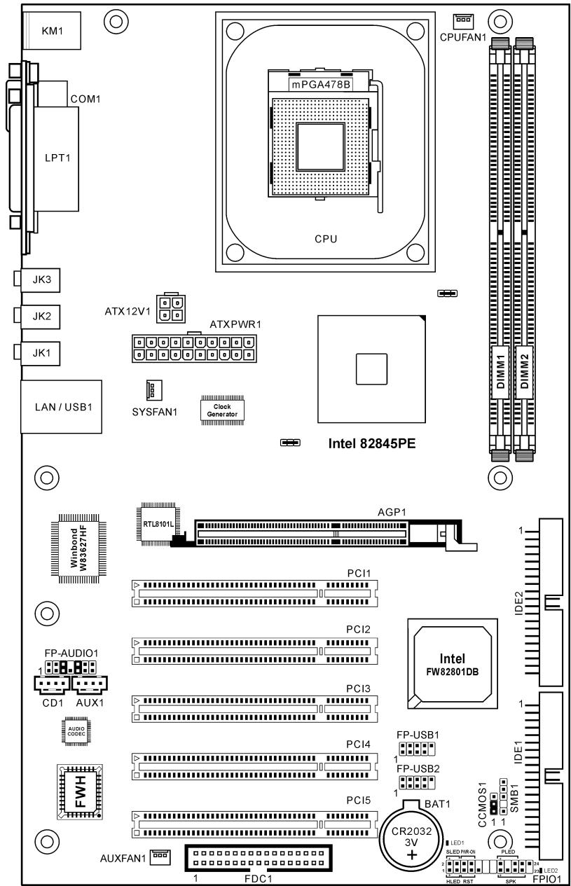
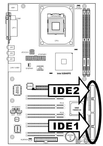
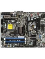
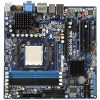
1-2. Layout Diagram
Chapter 2. Hardware Setup
Before the Installation: Turn off the power supply switch (fully turn off the +5V standby power), or disconnect the power cord before installing or unplugging any connectors or add-on cards. Failing to do so may cause the motherboard components or add-on cards to malfunction or damaged.
2-1. Install The Motherboard
Most computer chassis have a base with many mounting holes to allow motherboard to be securely attached on and at the same time, prevented from short circuits. There are two ways to attach the motherboard to the chassis base:
- use with studs
- or use with spacers
In principle, the best way to attach the board is to use with studs. Only if you are unable to do this should you attach the board with spacers. Line up the holes on the board with the mounting holes on the chassis. If the holes line up and there are screw holes, you can attach the board with studs. If the holes line up and there are only slots, you can only attach with spacers. Take the tip of the spacers and insert them into the slots. After doing this to all the slots, you can slide the board into
position aligned with slots. After the board has been positioned, check to make sure everything is OK before putting the chassis back on.

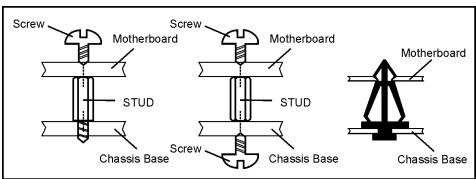
ATTENTION: To prevent shorting the PCB circuit, please REMOVE the metal studs or spacers if they are already fastened on the chassis base and are without mounting-holes on the motherboard to align with.
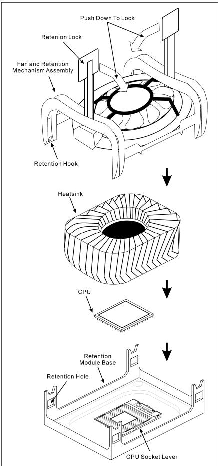
2-2. Install Pentium® 4 CPU and Heatsink Supporting-Base
This motherboard provides a ZIF (Zero Insertion Force) Socket 478 to install Intel Pentium CPU. The CPU you bought should have a kit of heatsink and cooling fan along with. If that's not the case, buy one specially designed for Pentium 4 Socket 478.
- Locate the 478-pin ZIF socket on the motherboard. Fasten the Retention Module Base onto the motherboard.
ATTENTION: If you are using chassis specially designed for Pentium 4, please pay attention to the location of metal studs or spacers if they are already installed on the chassis. Be careful not let the metal studs or spacers contact the printed circuit wire or parts on the PCB.
- Pull the CPU socket lever sideways away from the socket and then upwards to 90 degree. Insert the CPU with the correct orientation. Do not use extra force to insert CPU; it only fits in one orientation. Close down the socket lever while holding down the CPU.
- Put the heatsink faces down onto the CPU until it completely covers the CPU.
- Put the Fan and Retention Mechanism Assembly onto the heatsink. Make sure all the four Retention Locks at each side of the Fan and Retention Mechanism Assembly snap into the Retention Holes.
- Push down the Retention Lock at both sides of the Fan and Retention Mechanism Assembly to lock up together with the Retention Module Base.
- The Fan and Retention Mechanism Assembly and Retention Module Base should now firmly lock up with each other with the heatsink inside.

ATTENTION: Do not forget to set the correct bus frequency and multiple for your processor.
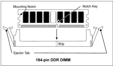
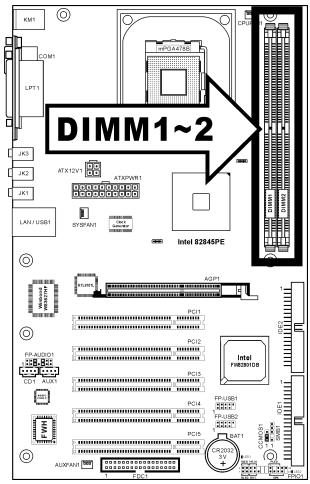
2-3. Install System Memory
This motherboard provides two 184-pin DDR DIMM slots for maximum memory expansion up to 2GB.
Table 2-1. Valid Memory Configurations
| Bank | Memory Module | Total Memory |
| Bank 0, 1 (DIMM1) | 128, 256, 512MB, 1GB | 128MB ~ 1GB |
| Bank 2, 3 (DIMM2) | 128, 256, 512MB, 1GB | 128MB ~ 1GB |
| Total System Memory | 128MB ~ 2GB | |
NOTE: No hardware or BIOS setup required after adding or removing memory modules.
Power off the computer and unplug the AC power cord before installing or removing memory modules.

- Locate the DIMM slot on the board.
- Hold two edges of the DIMM module carefully, keep away of touching its connectors.
- Align the notch key on the module with the rib on the slot.
- Firmly press the module into the slots until the ejector tabs at both sides of the slot automatically snaps into the mounting notch. Do not force the DIMM module in with extra force as the DIMM module only fit in one direction.
- To remove the DIMM modules, push the two ejector tabs on the slot outward simultaneously, and then pull out the DIMM module.
ATTENTION: Static electricity can damage the electronic components of the computer or optional boards. Before starting these procedures, ensure that you are discharged of static electricity by touching a grounded metal object briefly.
2-4. Connectors, Headers and Switches
Here we will show you all of the connectors, headers and switches, and how to connect them. Please read the entire section for necessary information before attempting to finish all the hardware installation inside the computer chassis. A complete enlarged layout diagram is shown in Chapter 1 for all the position of connectors and headers on the board that you may refer to.
WARNING: Always power off the computer and unplug the AC power cord before adding or removing any peripheral or component. Failing to so may cause severe damage to your motherboard and/or peripherals. Plug in the AC power cord only after you have carefully checked everything.
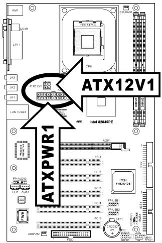
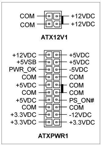
(1).ATX Power Input Connectors
The Pentium 4 requires a power supplier different from the regular one. It's a newly designed ATX12V power with 300W , 20A + 5VDC capacity at least for heavily loaded system, and 720mA + 5VSB at least for supporting Wake-On-LAN feature.
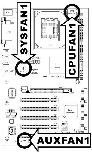
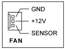
(2). FAN Connectors
These 3-pin connectors each provide power to the cooling fans installed in your system.
The CPU must be kept cool by using a powerful fan with heatsink. The system is capable of monitoring the speed of the CPU fan.
- CPUFAN1: CPU Fan
- SYSFAN1: System Fan
AUXFAN1: Auxiliary Fan
WARNING: These fan connectors are not jumpers. DO NOT place jumper caps on these connectors.
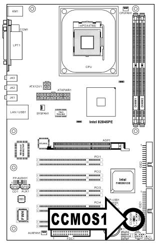
(3). CMOS Memory Clearing Header
This header uses a jumper cap to clear the CMOS memory.
Pin 1-2 shorted (default): Normal operation.
Pin 2-3 shorted: Clear CMOS memory.
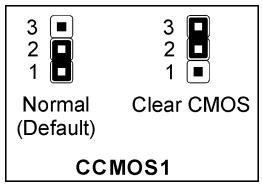
WARNING: Turn the power off first (including the +5V standby power) before clearing the CMOS memory. Failing to do so may cause your system to work abnormally or malfunction.
(4). Front Panel Audio Connection Header
This header provides the connection to audio connector at front panel.
- To use the audio connector at front panel, remove all the jumpers on this header, and then connect to front panel by the extension cable provided with the chassis.
- To use the audio connector at rear panel, disconnect the extension cable, attach the jumpers back at pin 5-6, and pin 9-10 (default setting).
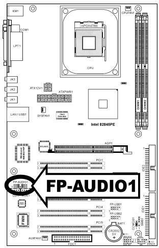
| 2 4 6 10 12 14 1 3 5 7 9 11 13 FP-AUDIO1 | Pin | Pin Assignment | Pin | Pin Assignment |
| 1 | Audio Mic. | 2 | Ground | |
| 3 | Audio Mic. Bias | 4 | VCC | |
| 5 | Speaker Out Right Channel | 6 | Speaker Out Right Channel Return | |
| 7 | X | 8 | NC | |
| 9 | Speaker Out Left Channel | 10 | Speaker Out Left Channel Return | |
| 11 | Ground | 12 | S/PDIF In | |
| 13 | VCC | 14 | S/PDIF Out |
(5). Front Panel Switches & Indicators Headers
This header is used for connecting switches and LED indicators on the chassis front panel.
Watch the power LED pin position and orientation. The mark "+" align to the pin in the figure below stands for positive polarity for the LED connection. Please pay attention to connect these headers. A wrong orientation will only cause the LED not lighting, but a wrong connection of the switches could cause system malfunction.
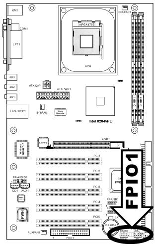
HLED (Pin 1,3):
Connects to the HDD LED cable of chassis front panel.
RST (Pin 5,7):
Connects to the Reset Switch cable of chassis front panel.
- SPK (Pin 15, 17, 19, 21):
Connects to the System Speaker cable of chassis.
- SLED (Pin 2, 4):
Connects to the Suspend LED cable (if there is one) of chassis front panel.
PWR-ON (Pin 6,8):
Connects to the Power Switch cable of chassis front panel.
- PLED (Pin 16, 18, 20):
Connects to the Power LED cable of chassis front panel.
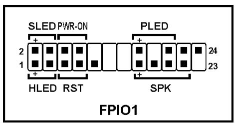
(6). Additional USB Port Headers
These headers each provide 2 additional USB 2.0 ports connection through an USB cable designed for USB 2.0 specifications.
| 2 4 6 8 10 1 3 5 7 FP-USB1 FP-USB2 | Pin | Pin Assignment | Pin | Pin Assignment |
| 1 | VCC | 2 | VCC | |
| 3 | Data0 - | 4 | Data1 - | |
| 5 | Data0 + | 6 | Data1 + | |
| 7 | Ground | 8 | Ground | |
| 9 | NC | 10 | NC |
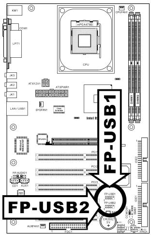
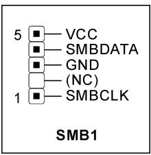
(7). System Management Bus Headers
This header is reserved for system management bus (SM bus). The SM bus is a specific implementation of an I^2C bus. I^2C is a multi-master bus, which means that multiple chips can be connected to the same bus and each one can act as a master by initiating a data transfer. If more than one master simultaneously tries to control the bus, an arbitration procedure decides which master gets priority.
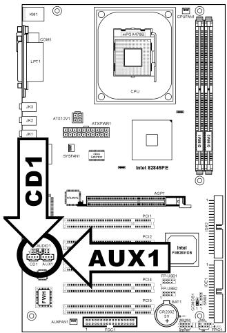
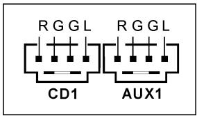
(8). Internal Audio Connectors
These connectors connect to the audio output of internal CD-ROM drive or add-on card.
(9). Accelerated Graphics Port Slot
This slot supports an optional AGP graphics card up to AGP 4X mode. Please refer to our Web site for more information on graphics cards.
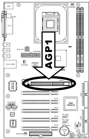
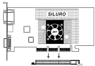
ATTENTION: This motherboard does not support 3.3V AGP cards. Use only 1.5V AGP cards.
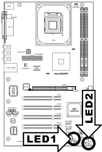
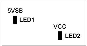
(10). Status Indicators
- LED1 (5VSB): This LED lights up when the power supply is connected with power source.
- LED2 (VCC): This LED lights up when the system power is on.
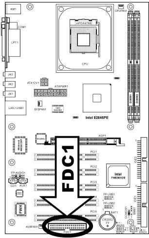
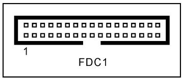
(11). Floppy Disk Drive Connector
This connector supports two standard floppy disk drives via a 34-pin 34-conductor ribbon cable.
Connecting the Floppy Disk Drive Cable:
- Install one end of the ribbon cable into the FDC1 connector. The colored edge of the ribbon cable should be aligned with pin-1 of FDC1 connector.
- Install the other end(s) of ribbon cable into the disk drive connector(s). The colored edge of the ribbon cable should be also aligned with pin-1 of disk drive connector. The endmost connector should be attached to the drive designated as Drive A.
(12). IDE Connectors
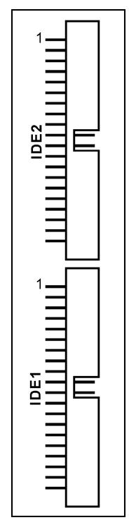
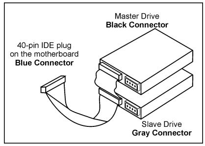
This motherboard provides two IDE ports to connect up to four IDE drives at Ultra ATA/100 mode by Ultra ATA/66 ribbon cables. Each cable has 40-pin 80-conductor and three connectors, providing two hard drives connection with motherboard. Connect the single end (blue connector) at the longer length of ribbon cable to the IDE port on motherboard, and the other two ends (gray and black connector) at the shorter length of the ribbon cable to the connectors on hard drives.
If you want to connect two hard drives together through one IDE channel, you must configure the second drive to Slave mode after the first Master drive. Please refer to the drives' documentation for jumper settings. The first drive connected to IDE1 is usually referred to as "Primary Master", and the second drive as "Primary Slave". The first drive connected to IDE2 is referred to as "Secondary Master" and the second drive as "Secondary Slave".
Keep away from connecting one legacy slow speed drive, like CD-ROM, together with another hard drive on the same IDE channel; this will drop your integral system performance.
(13). Back Panel Connectors
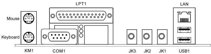
- Mouse: Connects to PS/2 mouse.
- Keyboard: Connects to PS/2 keyboard.
- LPT1: Connects to printer or other devices that support this communication protocol.
COM1: Connects to external modem, mouse or other devices that support this communication protocol. - JK3 (Line Out): Connects to headphone or an external powered stereo speaker.
- JK2 (Line In): Connects to the line out from external audio sources.
- JK1 (Mic In): Connects to the plug from external microphone.
LAN: Connects to Local Area Network. - USB1: Connects to USB devices such as scanner, digital speakers, monitor, mouse, keyboard, hub, digital camera, joystick etc.
Chapter 3. BIOS Setup
This motherboard provides a programmable EEPROM that you can update the BIOS utility. The BIOS (Basic Input/Output System) is a program that deals with the basic level of communication between processor and peripherals. Use the BIOS Setup program only when installing motherboard, reconfiguring system, or prompted to "Run Setup". This chapter explains the Setup Utility of BIOS utility.
After powering up the system, the BIOS message appears on the screen, the memory count begins, and then the following message appears on the screen:
PRESS DEL TO ENTER SETUP
If this message disappears before you respond, restart the system by pressing <Ctrl> + <Alt> + <Del> keys, or by pressing the Reset button on computer chassis. Only when it failed by these two methods can you restart the system by powering it off and then back on.
After pressing <Del> key, the main menu screen appears.
NOTE: In order to increase system stability and performance, our engineering staffs are constantly improving the BIOS menu. The BIOS setup screens and descriptions illustrated in this manual are for your reference only, may not completely match what you see on your screen.
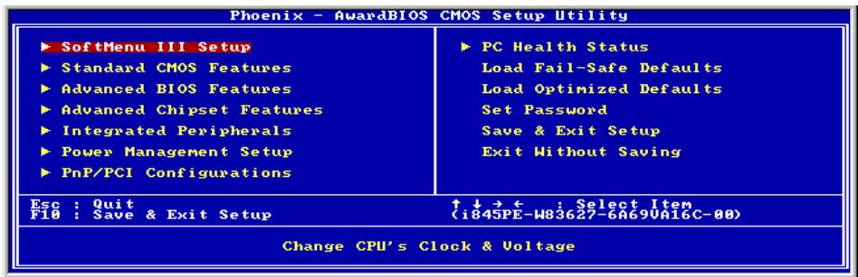
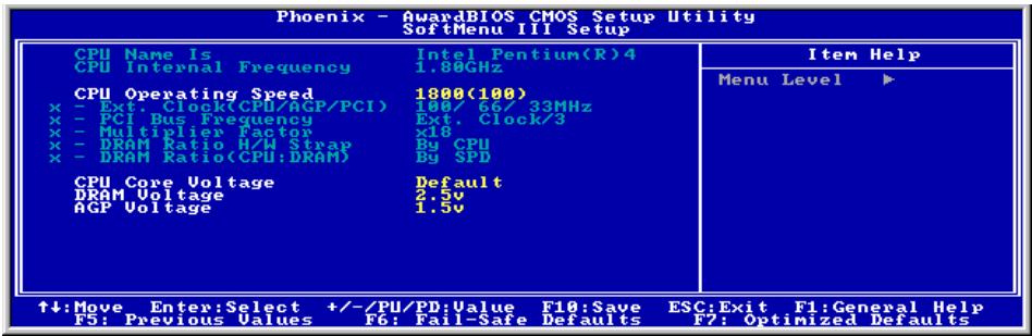
3-1. SoftMenu Setup
The SoftMenu utility is ABIT's exclusive and ultimate solution in programming the CPU operating speed. All the parameters regarding CPU FSB speed, multiplier factor, the AGP & PCI clock, and even the CPU core voltage are all available at your fingertips.
CPU Name Is:
This item displays the CPU model name, for example: Intel Pentium (R) 4.
CPU Internal Frequency:
This item displays the processor speed.
CPU Operating Speed:
This item displays the CPU operating speed according to the type and speed of your CPU. You can also select the [User Define] option to enter the manual option.
User Define:
WARNING: The wrong settings of the multiplier and external clock in certain circumstances may cause CPU damage. Setting the working frequency higher than the PCI chipset or processor specs, may cause abnormal memory module functioning, system hangs, hard disk drive data lose, abnormal functioning of the VGA card, or abnormal functioning with other add-on cards. Using non-specification settings for your CPU is not the intention of this explanation. These should be used for engineering testing, not for normal applications.
There will be no guaranty for the settings beyond specification, any damage of any component on this motherboard or peripherals result therein is not our responsibility.
\* Ext. Clock (CPU/AGP/PCI):
After choosing the "CPU Operating Speed" option as "User Define", you can choose the external clock frequency from 100MHz to 250 MHz.
管 PCI Bus Frequency:
This item determines the PCI bus frequency.
\* Multiplier Factor:
This item selects the multiplier factors for your CPU if it is not locked.
* DRAM Ratio H/W Strap:
This item sets the external hardware reset strap assigned to MCH (Memory Controller Hub).
To set this option manually:
- Select [Low] for CPU of 400MHz FSB frequency.
- Select [High] for CPU of 533MHz FSB frequency.
* DRAM Ratio (CPU:DRAM):
This item determines the frequency ratio between CPU and DRAM. The options are: 1:1 and 3:4 (under Low "DRAM Ratio H/W Strap" setting), or 4:5 and 1:1 (under High "DRAM Ratio H/W Strap" setting).
CPU Core Voltage:
This item selects the CPU core voltage.
ATTENTION: A wrong voltage setting may cause the system unstable or even damage the CPU. Please leave it to default setting unless you are fully aware of its consequences.
DRAM Voltage:
This item selects the voltage for DRAM slot.
AGP Voltage:
This item selects the voltage for AGP slot.
3-2. Standard CMOS Features
This section contains the basic configuration parameters of the BIOS. These parameters include date, hour, VGA card, FDD and HDD settings.
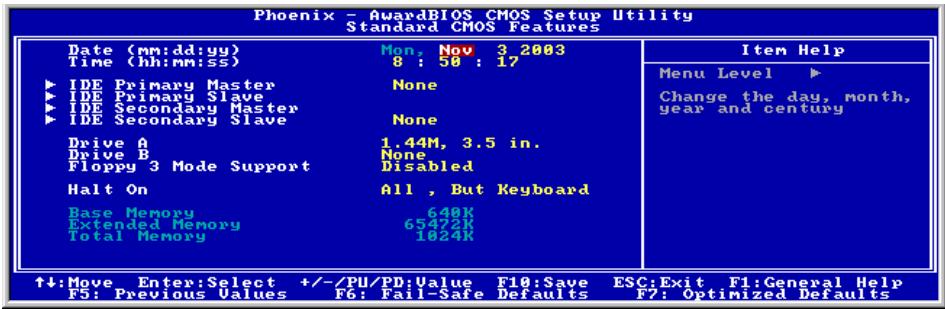
Date (mm:dd:yy):
This item sets the date you specify (usually the current date) in the format of [Month], [Date], and [Year].
Time (hh:mm:ss):
This item sets the time you specify (usually the current time) in the format of [Hour], [Minute], and [Second].

IDE Primary Master/Slave, IDE Secondary Master/Slave:
Click
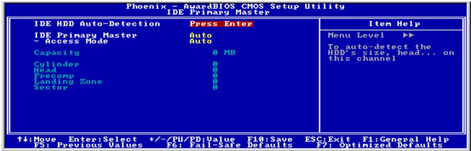
IDE HDD Auto-Detection:
This item allows you to detect the parameters of IDE drives by pressing
IDE Primary/Secondary Master/Slave
When set to [Auto], the BIOS will automatically check what kind of IDE drive you are using. If you want to define your own drive by yourself, set it to [Manual] and make sure you fully understand the meaning of the parameters. Please refer to the instruction manual provided by the device's manufacturer to get the setting right.
Access Mode:
This item selects the mode to access your IDE devices. Leave this item to its default [Auto] setting to detect the access mode of your HDD automatically.
Capacity:
This item displays the approximate capacity of the disk drive. Usually the size is slightly greater than the size of a formatted disk given by a disk-checking program.
Cylinder:
This item configures the numbers of cylinders.
Head:
This item configures the numbers of read/write heads.
Precomp:
This item displays the number of cylinders at which to change the write timing.
Landing Zone:
This item displays the number of cylinders specified as the landing zone for the read/write heads.
Sector:
This item configures the numbers of sectors per track.

Back to Standard CMOS Features Setup Menu:
Drive A & Drive B:
This item sets the type of floppy drives (usually only Drive A) installed.
Floppy 3 Mode Support:
This item allows you to use "3 Mode Floppy Drive" in Japanese computer system by selecting drive A, B, or both. Leave this item to its default [Disabled] setting if you are not using this Japanese standard floppy drive.
Halt On:
This item determines whether the system stops if an error is detected during system boot-up.
[All Errors]: The system-boot will stop whenever the BIOS detect a non-fatal error.
[No Errors]: The system-boot will not stop for any error detected.
[All, But Keyboard]: The system-boot will stop for all errors except a keyboard error.
[All, But Diskette]: The system-boot will stop for all errors except a diskette error.
[All, But Disk/Key]: The system-boot will stop for all errors except a diskette or keyboard error.
Base Memory:
This item displays the amount of base memory installed in the system. The value of the base memory is typically 640K for system with 640K or more memory size installed on the motherboard.
Extended Memory:
This item displays the amount of extended memory detected during system boot-up.
Total Memory:
This item displays the total memory available in the system.
3-3. Advanced BIOS Features
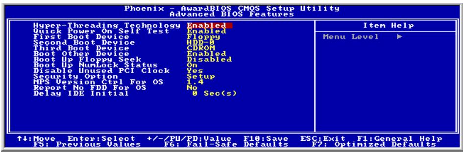
Hyper-Threading Technology
This item is used to enable the functionality of the processor with Hyper-Threading Technology and will appear only when using such processor.
The Hyper-Threading Technology helps your PC work more efficiently by maximizing processor resources and enabling a single processor to run two separate threads of software simultaneously, bringing forth greater performance and system responsiveness when running multiple applications at once.
Quick Power On Self Test:
When set to [Enabled], this item speeds up the Power On Self Test (POST) after powering on the system. The BIOS shorten or skip some check during the POST.
First Boot Device / Second Boot Device / Third Boot Device / Boot Other Device:
Select the drive to boot first, second and third in the [First Boot Device], [Second Boot Device], and [Third Boot Device] items respectively. The BIOS will boot the operating system according to the sequence of the drive selected. Set [Boot Other Device] to [Enabled] if you wish to boot from another device other than these three items.
Boot Up Floppy Seek:
When set to [Enabled], the BIOS will check whether the floppy disk drive is installed or not.
Boot Up NumLock Status:
This item determines the default state of the numeric keypad at system booting up.
[On]: The numeric keypad functions as number keys.
[Off]: The numeric keypad functions as arrow keys.
Disable Unused PCI Clock:
This option disables the clock of PCI slot that is not in use.
[Yes]: The system automatically detect the unused DIMM and PCI slots, and stop sending clock signal to these unused PCI slots.
[No]: The system always send clock signal to all PCI slots.
NOTE: Set this option to [No] setting if there are adapters that cannot be automatically detected by the system and will cause malfunction.
Security Option:
This item determines when the system will prompt for password - every time the system boots or only when enters the BIOS setup.
[Setup]: The password is required only when accessing the BIOS Setup.
[System]: The password is required each time the computer boots up.
NOTE: Don't forget your password. If you forget the password, you will have to open the computer case and clear all information in the CMOS before you can start up the system. But by doing this, you will have to reset all previously set options.
MPS Version Ctrl For OS:
This item specifies which version of MPS (Multi-Processor Specification) this motherboard will use. Leave this item to its default setting.
Report No FDD For OS:
When set to [Yes], this item allows you to run some older operating system without floppy disk drive. Leave this item to its default setting.
Delay IDE Initial (Secs):
This item allows the BIOS to support some old or special IDE devices by prolonging this delay time. A larger value will give more delay time to the device for which to initialize and to prepare for activation.
3-4. Advanced Chipset Features
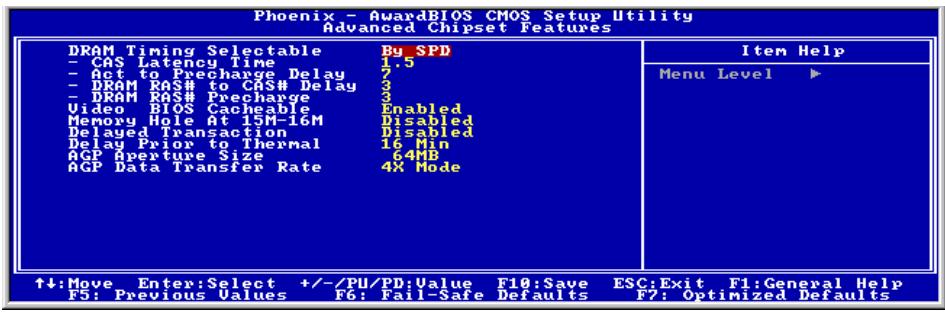
DRAM Timing Selectable:
This item sets the optimal timings for the following four items, depending on the memory module you are using. The default setting "By SPD" configures these four items by reading the contents in the SPD (Serial Presence Detect) device. The EEPROM on the memory module stores critical parameter information about the module, such as memory type, size, speed, voltage interface, and module banks.
\* CAS Latency Time:
This item controls the latency between the DRAM read command and the time that the data becomes actually available.
\* Act to Precharge Delay:
This item controls the number of DRAM clocks used for the DRAM parameters.
DRAM RAS# to CAS# Delay
This item controls the latency between the DRAM active command and the read/write command.
* DRAM RAS# Precharge:
This item controls the idle clocks after issuing a precharge command to the DRAM.
Video BIOS Cacheable:
As with caching the system BIOS, enabling the Video BIOS cache will allow access to video BIOS addressed at C0000H to C7FFFH to be cached, if the cache controller is also enabled. The larger the range of the Cache RAM, the faster the video performance will be.
Memory Hole At 15M-16M:
When set to [Enabled], the memory address space at 15M-16M will be reserved for ISA expansion cards that specifically requires this setting. This makes the memory from 15MB and up unavailable to the system. Leave this item to its default setting.
Delayed Transaction:
Two options are available: Enabled and Disabled. The default setting is Disabled. Set the option to enabled or disabled PCI 2.1 features including passive release and delayed transaction for the chipset. This function is used to meet the latency of PCI cycles to or from the ISA bus. This option must be enabled to provide PCI 2.1 compliance. If you have an ISA card compatibility problem, you can try to enable or disable this option for optimal results.
Delay Prior to Thermal:
This item selects the delay time before thermal activation.
AGP Aperture Size:
This option specifies the amount of system memory that can be used by the AGP device. The aperture is a portion of the PCI memory address range dedicated for graphics memory address space.
AGP Data Transfer Rate:
This item selects the data transfer rate of AGP device. A higher rate delivers faster and better graphics to your system. Make sure your graphics card supports the mode you select.
3-5. Integrated Peripherals
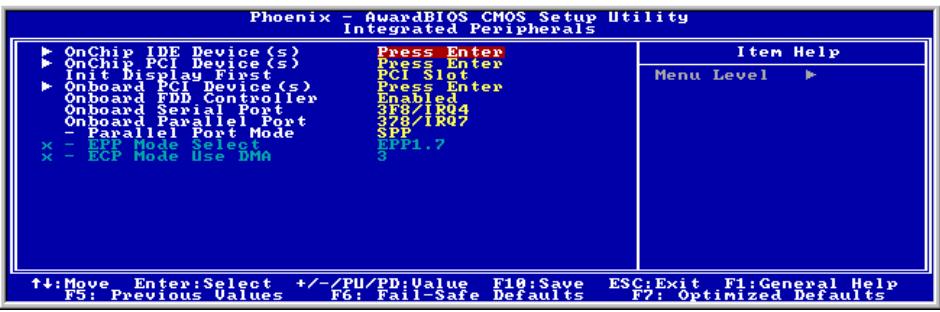

OnChip IDE Device(s):
Click
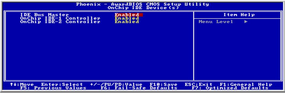
IDE Bus Master:
This option enables or disables the IDE Bus Master controller.
OnChip IDE-1 Controller:
This item allows you to enable or disable the primary and secondary IDE controller. Select [Disabled] if you want to add a different hard drive controller.
OnChip IDE-2 Controller:
The description is same as the OnChip IDE-1 Controller.

OnChip PCI Device(s):
Click
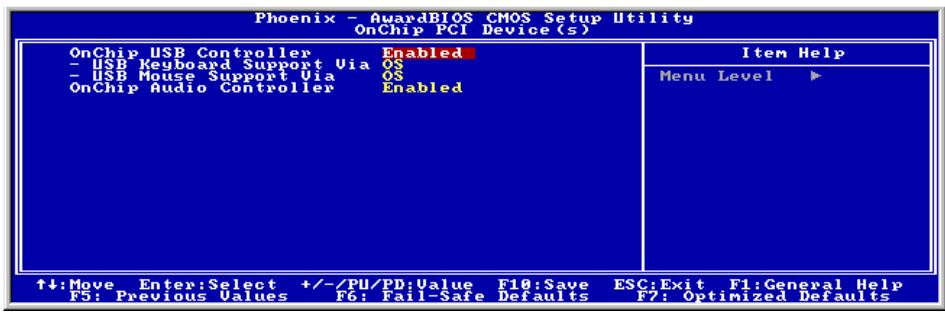
OnChip USB Controller:
This option enables or disables the USB controller.
\* USB Keyboard Support Via:
This item allows you to select [BIOS] for using USB keyboard in DOS environment, or [OS] in OS environment.
\* USB Mouse Support Via:
This item allows you to select [BIOS] for using USB mouse in DOS environment, or [OS] in OS environment.
OnChip Audio Controller:
This option enables or disables the audio controller.

Back to Integrated Peripherals Setup Menu:
Init Display First:
This item selects to initialize AGP or PCI Slot first when the system boots.
[AGP]: When the system boots, it will first initialize AGP.
[PCI Slot]: When the system boots, it will first initialize PCI.

Onboard PCI Device(s):
Click
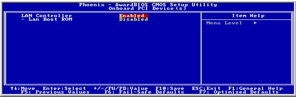
LAN Controller:
This option enables or disables the LAN controller.
\* LAN Boot ROM:
This item allows you to use the boot ROM (instead of a disk drive) to boot-up the system and access the local area network directly.

Back to Integrated Peripherals Setup Menu:
Onboard FDD Controller:
This option enables or disables the onboard FDD controller.
Onboard Serial Port:
This item determines which I/O addresses the onboard Serial Port controller will access.
[Auto]: The system automatically select an I/O address for the onboard Serial Port.
[3F8/IRQ4, 2F8/IRQ3, 3E8/IRQ4, 2E8/IRQ3]: Allows you to manually select an I/O address for the onboard Serial Port.
[Disabled]: Disables the onboard Serial Port.
Onboard Parallel Port:
This item specifies the I/O address used by the parallel port.
[Disabled]: This option prevents the parallel port from accessing any system resources. When the value of this option is set to [Disabled], the printer port becomes unavailable.
[378/IRQ7]: This option allows the parallel port to use [378/IRQ7] as its I/O port address. The majority of parallel ports on computer systems use IRQ7 and I/O Port 378H as the standard setting.
[278/IRQ5]: This option allows the parallel port to use [278/IRQ5] as its I/O port address.
[3BC/IRQ7]: This option allows the parallel port to use [3BC/IRQ7] as its I/O port address.
* Parallel Port Mode:
This item specifies the parallel port mode.
[Normal]: Allows the standard parallel port mode to be used.
[SPP]: (Standard Parallel Port) Allows bi-directional parallel port operation at normal speed.
[EPP]: (Enhanced Parallel Port) Allows bi-directional parallel port operation at maximum speed.
[ECP]: (Extended Capabilities Port) Allows bi-directional parallel port operation at a speed faster than the normal mode's data transfer rate.
[ECP+EPP]: Allows parallel port operation at ECP and EPP mode.
* EPP Mode Select:
This item selects the EPP mode.
* ECP Mode Use DMA:
This item selects the DMA channel of the parallel port.
3-6. Power Management Setup
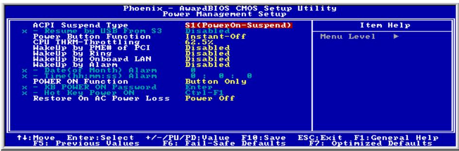
ACPI Suspend Type:
This item selects the type of Suspend mode.
[S1(PowerOn-Suspend)]: Enables the Power On Suspend function.
[S3(Suspend-To-RAM)]: Enables the Suspend to RAM function.
*Resume by USB From S3:
When set to [Enabled], this item allows you to use a USB device to wake up a system that is in the S3 (STR - Suspend To RAM) state. This item can be configured only if the item "ACPI Suspend Type" is set to [S3(STR)].
Power Button Function:
This item selects the method of powering off your system:
[Delay 4 Sec.]: Pushing the power button for more than 4 seconds will power off the system. This will prevent the system from powering off in case you accidentally hit or pushed the power button.
[Instant-Off]: Pressing and then releasing the power button at once will immediately power off the system.
CPU THRM-Throttling
This item controls the CPU speed by cutting down its regular power to a percentage during the STR (Suspend To RAM) state.
WakeUp by PME# of PCI:
When set to [Enabled], access to the onboard LAN or a PCI card such as a modem or LAN card will cause the system to wake up. The PCI card must support the wake up function.
WakeUp by Ring:
When set to [Enabled], telephone calls coming through an external or internal modem will power-on your system.
WakeUp by Onboard Lan:
When set to [Enabled], you can remotely wake up a PC in Soft-Off condition via a LAN card that supports the wake up function.
WakeUp by Alarm:
When set to [Enabled], you can set the date and time you would like the Soft-Off PC to power-on in the "Date (of Month) Alarm" and "Time (hh:mm:ss) Alarm" items. However, if the system is being accessed by incoming calls or the network (Resume On Ring/LAN) prior to the date and time set in these items, the system will give priority to the incoming calls or network instead.
\* Date (of Month) Alarm
[0]: This option power-on the system everyday according to the time set in the "Time (hh:mm:ss) Alarm" item.
[1-31]: This option selects a date you would like the system to power-on. The system will power-on on the date set, and the time set in the "Time (hh:mm:ss) Alarm" item.
* Time (hh:mm:ss) Alarm
This item sets the time you would like the system to power-on.
POWER ON Function:
This item selects the way you want your system to power on.
[Password]: Use a password to power on the system, select this option then press
[Hot Key]: Use any of the function keys between < F1 > to < F12 > to power on the system.
[Mouse Left]: Double click the mouse left button to power on the system.
[Mouse Right]: Double click the mouse right button to power on the system.
[Any KEY]: Use any keyboard keys to power on the system.
[Button Only]: Use only the power button to power on the system.
[Keyboard 98]: Use the power-on button on the "Keyboard 98" compatible keyboard to power on the system.
NOTE: The mouse wake up function can only be used with the PS/2 mouse, not with the COM port or USB type. Some PS/2 mice cannot wake up the system because of compatible problems. If the specs of your keyboard are too old, it may fail to power on.
* KB Power ON Password:
This item sets the password required in order to power on your computer.
NOTE: Do not forget your password, or you will have to clear the CMOS and reset all parameters in order to utilize this function again.
Hot Key Power ON:
This item powers on the system by pressing Ctrl key plus one of each function key ( F1 F12 ) simultaneously.
Restore On AC Power Loss:
This item selects the system action after an AC power failure.
[Power Off]: When power returns after an AC power failure, the system's power remains off. You must press the Power button to power-on the system.
[Power On]: When power returns after an AC power failure, the system's power will be powered on automatically.
[Last State]: When power returns after an AC power failure, the system will return to the state where you left off before power failure occurs. If the system's power is off when AC power failure occurs, it will remain off when power returns. If the system's power is on when AC power failure occurs, the system will power-on when power returns.
3-7. PnP/PCI Configurations
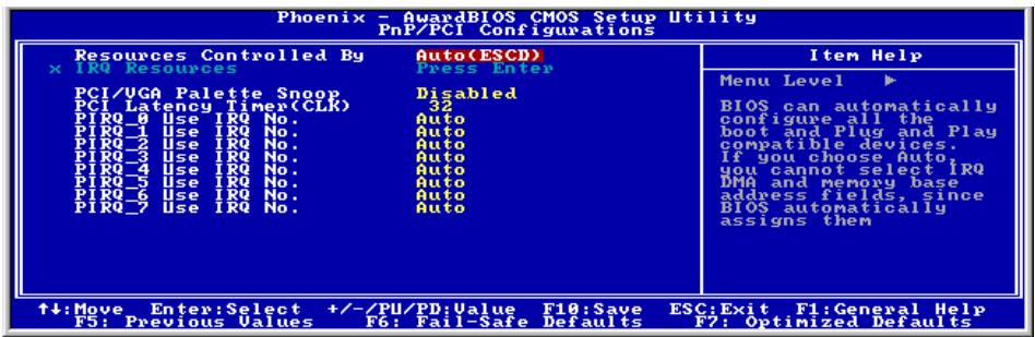
Resources Controlled By:
This item configures all of the boot and Plug-and-Play compatible devices.
[Auto(ESCD)]: The system will automatically detect the settings.
[Manual]: Choose the specific IRQ resources in the "IRQ Resources" menu.
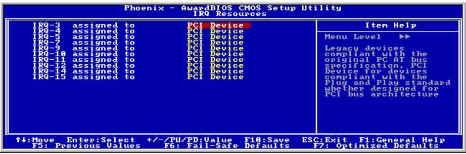
* IRQ Resources:
Click
This item sets each system interrupt to either [PCI Device] or [Reserved].
PCI/VGA Palette Snoop:
This item determines whether the MPEG ISA/VESA VGA cards can work with PCI/VGA or not.
[Enabled]: MPEG ISA/VESA VGA cards work with PCI/VGA.
[Disabled]: MPEG ISA/VESA VGA cards do not work with PCI/VGA.
PCI Latency Timer(CLK):
This item controls how long each PCI device can hold the bus before another takes over. When set to higher values, every PCI device can conduct transactions for a longer time and thus improve the effective PCI bandwidth. For better PCI performance, you should set the item to higher values.
PIRO 0 Use IRO No.~PIRO 7 Use IRO No.:
This item specifies the IRQ number manually or automatically for the devices installed on PCI slots.
For the relations between the hardware layout of PIRQ (the signals from the ICH chipset), INT# (means PCI slot IRQ signals) and devices, please refer to the table below:
| Signals | AGP | LAN | PCI-1 | PCI-2 | PCI-3 | PCI-4 | PCI-5 |
| PIRQ_0 Assignment | INT A | INT D | |||||
| PIRQ_1 Assignment | INT B | INT A | |||||
| PIRQ_2 Assignment | INT B | ||||||
| PIRQ_3 Assignment | INT A | INT C | |||||
| PIRQ_4 Assignment | INT A | INT B | INT C | INT D | |||
| PIRQ_5 Assignment | INT B | INT C | INT D | INT A | |||
| PIRQ_6 Assignment | INT C | INT D | INT A | INT B | |||
| PIRQ_7 Assignment | INT D | INT A | INT B | INT C |
3-8. PC Health Status
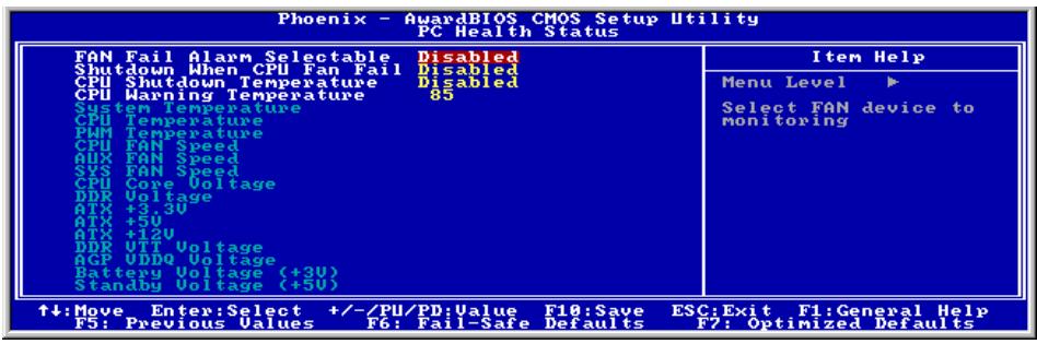
FAN Fail Alarm Selectable:
This item selects the fan that will be monitored for malfunction.
Shutdown When CPUFAN Fail:
When set to [Enabled], the system will be shut down if the CPU fan is not running.
CPU Shutdown Temperature:
This item sets the temperature that would shutdown the system automatically in order to prevent system overheats.
CPU Warning Temperature:
This item selects the CPU's warning temperature limit. Once the system has detected that the CPU's temperature exceeded the limit, warning beeps will sound.
NOTE: The onboard hardware monitor function is capable of detecting these system health conditions. If you want a warning message to pop-up or a warning alarm to sound when an abnormal condition occurs, you must install the "Hardware Doctor" utility. This utility is included in the "Driver & Utility CD" that came packed with this motherboard.
All Voltages, Fans Speed and Thermal Monitoring:
These unchangeable items list the current status of the CPU and environment temperatures, fan speeds, and system power voltage.
NOTE: The hardware monitoring features for temperatures, fans and voltages will occupy the I/O address from 294H to 297H. If you have a network adapter, sound card or other add-on cards that might use those I/O addresses, please adjust your add-on card I/O address to avoid using these addresses.
3-9. Load Fail-Safe Defaults
This option loads the BIOS default values for the most stable, minimal-performance system operations.
3-10. Load Optimized Defaults
This option loads the BIOS default values that are factory settings for optimal-performance system operations.
3-11. Set Password
This option protects the BIOS configuration or restricts access to the computer itself.
3-12. Save & Exit Setup
This option saves your selections and exits the BIOS setup menu.
3-13. Exit Without Saving
This option exits the BIOS setup menu without saving any change.
Appendix A. Install Intel Chipset Software Utility
NOTE: Please install this Intel Chipset driver first after having installed the Windows operating system.
The installation procedures and screen shots in this section are based on Windows 2000 operating system. For those of other OS, please follow its on-screen instruction.
Insert the Driver & Utility CD into CD-ROM drive, it should execute the installation program automatically. If not, double-click the execution file at the main directory of this CD to enter the installation menu.
After entering the installation menu, move your curser to [Drivers] tab. Click [Intel Chipset Software Utility]. The following screen appears.
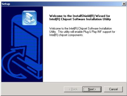
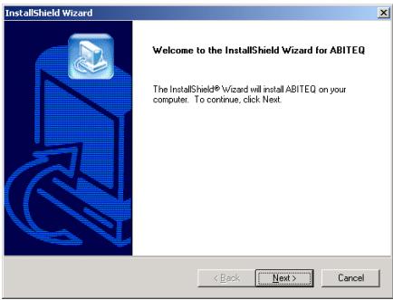
1. Click [Next].
![ABIT BE7II - Click [Next]. - 1](/content/2025/01/174520/images/d6d4d2996a1e53762fa42017827aaac1a1e85d6edfda2dcedfa8a2af1a5c9377.jpg)
2. Click [Yes].
![ABIT BE7II - Click [Yes]. - 1](/content/2025/01/174520/images/f8148fb35e674b12134d405e84f279179c935eb0b3b67186366aab90feac3798.jpg)
3. Click [Next].
![ABIT BE7II - Click [Next]. - 1](/content/2025/01/174520/images/26bf64e53dc6f31c784bcd7cbd68ea86309cc8b98eed207865018caf5f354e15.jpg)
- Choose [Yes, I want to restart my computer now.], and click [Finish] to complete setup.
![ABIT BE7II - Click [Next]. - 2](/content/2025/01/174520/images/72ff6c2500f36ce2d5ac29708d78290abe43681652f0ff2fbd85bb3fca39c5fd.jpg)
Appendix B. Install Intel Application Accelerator
The installation procedures and screen shots in this section are based on Windows 2000 operating system. For those of other OS, please follow its on-screen instruction.
Insert the Driver & Utility CD into CD-ROM drive, it should execute the installation program automatically. If not, double-click the execution file at the main directory of this CD to enter the installation menu.
After entering the installation menu, move your curser to [Drivers] tab. Click [Intel Application Accelerator]. The following screen appears.
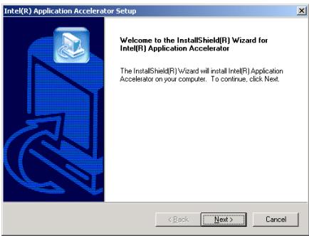
1. Click [Next].
![ABIT BE7II - Click [Next]. - 1](/content/2025/01/174520/images/51bdcb2b2d04c88c2822f353189a43ab9aa9746fb24ce17529523485b36954fa.jpg)
2. Click [Yes].
![ABIT BE7II - Click [Yes]. - 1](/content/2025/01/174520/images/ffeed636eb86e2ecc53f7def27e7057ada701757e6b2ee0eadfeb0bdff13ebfb.jpg)
3. Click [Next].
![ABIT BE7II - Click [Next]. - 1](/content/2025/01/174520/images/7f70d79a9dd4f754ebdb40f8cc75a48499965d21d960a2b45bed7677c9714f80.jpg)
4. Click [Next].
![ABIT BE7II - Click [Next]. - 1](/content/2025/01/174520/images/e760c906fc440012d961194ed2d068f6e0e5bec64a3ba91f10a6035b2e09e0bf.jpg)
- Choose [Yes, I want to restart my computer now.], and click [Finish] to complete setup.
![ABIT BE7II - Click [Next]. - 2](/content/2025/01/174520/images/2936a6e84af00b557fbb5809682588d57524ece1c496e687a517098864e0cb86.jpg)
Appendix C. Install Audio Driver
The installation procedures and screen shots in this section are based on Windows 2000 operating system. For those of other OS, please follow its on-screen instruction.
Insert the Driver & Utility CD into CD-ROM drive, it should execute the installation program automatically. If not, double-click the execution file at the main directory of this CD to enter the installation menu.
After entering the installation menu, move your curser to [Drivers] tab. Click [Audio Driver]. The following screen appears.
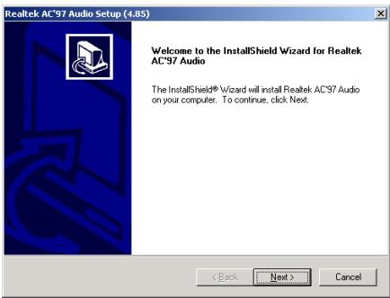
- Click [Next].
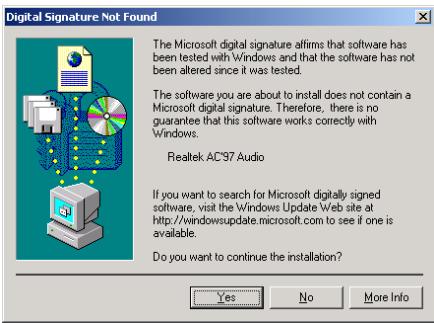
- Click [Yes].
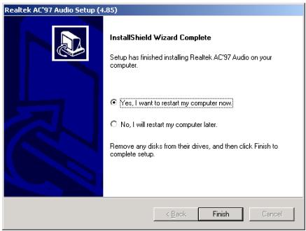
- Choose [Yes, I want to restart my computer now.], and click [Finish] to complete setup.

- After the system restarted, a shortcut icon appears at the right corner of Windows task bar.
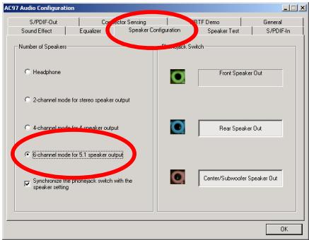
- In this Speaker Configuration tab, select [6 channels mode for 5.1 speakers output] to enable 6-channel audio system.

Appendix D. Install LAN Driver
The installation procedures and screen shots in this section are based on Windows 2000 operating system. For those of other OS, please follow its on-screen instruction.
Insert the Driver & Utility CD into CD-ROM drive, it should execute the installation program automatically. If not, double-click the execution file at the main directory of this CD to enter the installation menu.
After entering the installation menu, move your cursor to [Drivers] tab. Click [LAN Driver]. The following screen appears.
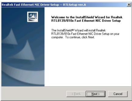
- Click [Next].
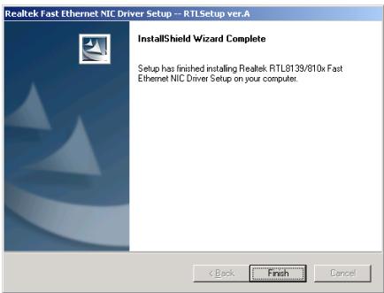
- Click [Finish] to complete setup.

Appendix E. Install USB 2.0 Driver
NOTE: The "USB 2.0 Driver" packed in the "Driver & Utility CD" is currently available for Windows 9x and ME only. To install this driver for Windows XP or Windows 2000, you have to download their latest service pack first from Microsoft's web site.
To install the USB 2.0 driver for Windows 9x and ME, please insert the Driver & Utility CD into CD-ROM drive. It should execute the installation program automatically. If not, double-click the execution file at the main directory of this CD to enter the installation menu. The following screen appears.
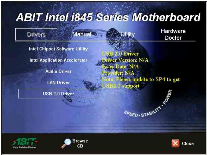
Click [USB 2.0 Driver], and then follow the on-screen instruction to complete the driver installation.

Appendix F. ABIT EQ (The Hardware Doctor Utility)
ABIT EQ is a self-diagnostic system for PC based on motherboards designed and manufactured by ABIT Computer Corporation. It will protect PC Hardware by monitoring critical items of Power Supply Voltage, CPU & System Fans Speed, and CPU & System Temperature.
The installation procedures and screen shots in this section are based on Windows 2000 operating system. For those of other OS, please follow its on-screen instruction.
Insert the Driver & Utility CD into CD-ROM drive, it should execute the installation program automatically. If not, double-click the execution file at the main directory of this CD to enter the installation menu.
After entering the installation menu, move your curser to [Hardware Doctor] tab. Click [ABIT EQ]. The following screen appears.
1. Click [Next].
![ABIT BE7II - Click [Next]. - 1](/content/2025/01/174520/images/a624810cc59a5f54fe9249c057d1ff271c7033977b6ac9f823a1c0e72c6d466a.jpg)
2. Click [Next].
![ABIT BE7II - Click [Next]. - 1](/content/2025/01/174520/images/972d7e5022411ce77553fdd2ec7e5c67c58f5f679ad532ba487fd847b4ae60f5.jpg)
3. Click [Next].
![ABIT BE7II - Click [Next]. - 1](/content/2025/01/174520/images/9045d5f770836db880b8df3a147138cab152377047596d3eb6e316c68f7c1afe.jpg)
4. Choose [Yes, I want to restart my computer now.] and click [Finish] to complete setup.
![ABIT BE7II - Choose [Yes, I want to restart my computer now.] and click [Finish] to complete setup. - 1](/content/2025/01/174520/images/8490e409cf4484baba44f9201d6321050dfcb63d5af58c2d9abfff784b49f504.jpg)
5. Execute the ABIT EQ by entering the Windows Menu [Start] [Programs] [ABIT] [ABIT EQ].
![ABIT BE7II - Execute the ABIT EQ by entering the Windows Menu [Start] [Programs] [ABIT] [ABIT EQ]. - 1](/content/2025/01/174520/images/10c973a99e52191c11e0142f026519bd88e4ea936a7e04993b9c4003c8df7c7a.jpg)
- This screen appears. ABIT EQ shows you the status of Voltage, Fan Speed, and Temperature readings as well.
Appendix G. Troubleshooting (Need Assistance?)
Q & A:
Q: Do I need to clear the CMOS before I use a new motherboard to assemble my new computer system?
A: Yes, we highly recommend that you clear the CMOS before installing a new motherboard. Please move the CMOS jumper from its default 1-2 position to 2-3 for a few seconds, and then back. When you boot up your system for the first time, follow the instructions in the user's manual to load the optimized defaults.
Q: If my systems hang when I update the BIOS or set the wrong CPU parameters, what should I do?
A: Whenever you update the BIOS or if the system hangs due to wrong CPU parameters setting, always clear CMOS jumper before booting up again.
Q: Why the system failed to boot up and nothing was displayed on the screen after I did some over-clocking or non-standard settings inside the BIOS? Is the motherboard dead? Do I need to return it to where I bought from or go through an RMA process?
A: It should not cause hardware or permanent damage to motherboard when BIOS settings were changed from default to over-clocking or non-standard status.
We suggest the following three troubleshooting methods to discharge CMOS data, recover the hardware default status, and then make the motherboard working again. No need to bother returning the motherboard to where you bought from or go through an RMA process.
Step 1. Switch off the power supply unit and then switch it on again after one minute. If there is no power switch on the power supply unit, disconnect its power cord for one minute and then connect it back.
Press and hold the key to enter the BIOS setup page to do the correct settings.
If the situation remains the same, repeat the procedures in Step 1 for three times, or try Step 2.
Step 2. Switch off the power supply unit or disconnect the power cord. Open the chassis cover.
Locate the CCMOS jumper near the button battery. Change the jumper position from default 1-2 to 2-3 for one minute to discharge the CMOS data, and then put it back to default 1-2 position.
Close the chassis and switch on the power supply unit or plug in the power cord. Press the power-on button to boot up system. If it works, hit <Del> key to enter the BIOS setup page to do the correct settings.
If the situation remains the same, try Step 3.
Step 3. The same procedure as Step 2, but in the meantime of discharging the CMOS data, pull out ATX power connectors from motherboard and remove the button battery during CMOS discharging.
Q: How can I get a quick response to my request for technical support?
A: Be sure to follow the guidelines as stated in the "Technical Support Form" section of this manual.
If you have a problem during operation, in order to help our technical support personnel quickly determine the problem with your motherboard and give you the answers you need, before filling in the technical support form, eliminate any peripheral that is not related to the problem, and indicate it on the form. Fax this form to your dealer or to the company where you bought the hardware in order to benefit from our technical support. (You can refer to the examples given below)
Example 1:
With a system including: motherboard (with CPU, DRAM, COAST...) HDD, CD-ROM, FDD, VGA CARD, MPEG CARD, SCSI CARD, SOUND CARD, etc. After the system is assembled, if you cannot boot up, check the key components of the system using the procedure described below. First remove all interface cards except the VGA card and try to reboot.
If you still cannot boot up: Try installing another brand/model VGA card and see if the system will start. If it still does not start, note the VGA card model, motherboard model, Bios identification number, CPU on the technical support form (refer to main instructions), and describe the problem in the problem description space provided.
If you can boot up: Insert the interface cards you have removed back into the system, one by one and try to start the system each time you insert a card, until the system will not start. Keep the VGA card and the interface card that caused the problem inserted on the motherboard, remove any other cards or peripheral, and start again. If you still cannot start, note the information related to both cards in the add-on Card space provided, and don't forget to indicate the motherboard model, version, BIOS identification number, CPU (refer to main instructions), and give a description of the problem.
Example 2:
With a system including the motherboard (with CPU, DRAM, COAST...) HDD, CD-ROM, FDD, VGA CARD, LAN CARD, MPEG CARD, SCSI CARD, SOUND CARD, after assembly and after having installed the Sound Card Driver, when you restart the system, when it runs the Sound Card Driver, it resets automatically. This problem may be due to the Sound Card Driver. During the Starting DOS... procedure, press SHIFT (BY-PASS) key, to skip CONFIG.SYS and AUTOEXEC.BAT; edit CONFIG.SYS with a text editor, and in function the line that loads the Sound Card Driver, add a remark REM, in order to disable the Sound Card Driver. See the example below.
CONFIG.SYS:
DEVICE=C:\DOS\HIMEM.SYS
DEVICE=C:\DOS\EMM386.EXE HIGHSCAN
DOS=HIGH, UMB
FILES=40
BUFFERS=36
REM DEVICEHIGH=C:\PLUGPLAY\DWCFGMG.SYS
LASTDRIVE = Z
Restart the system. If the system starts and does not reset, you can be sure that the problem is due to the Sound Card Driver. Write down the Sound Card model, motherboard model, BIOS identification number on the technical support file (refer to main instructions), and describe the problem in the space provided.
We will show you how to fill the "Technical Support Form".
Main instructions:
To fill in this "Technical Support Form", refer to the step-by-step instructions given below:
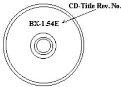
1*.MODEL: Note the model number given in your user's manual.
Example: BE7II.
2. Motherboard model number (REV): Note the motherboard model number labeled on the motherboard as "REV:**".
Example: REV: 1.01
-
BIOS ID and Part Number: See the on screen message.
-
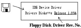
DRIVER REV: Note the driver version number indicated on the DEVICE DRIVER disk (if any) as "Release .*". For example:
5*. OS/APPLICATION: Indicate the operating system and applications you are running on the system.
Example: MS-DOS® 6.22, Windows® 98 SE, Windows® 2000, etc....
6^* CPU: Indicate the brand and the speed (MHz) of your CPU.
Example:(A) In the "Brand" space, write "Intel"; in the "Specifications" space, write "Pentium® 4 1.9GHz".
- HDD: Indicate the brand and specifications of your HDD(s); specify if the HDD is using IDE1 or IDE2. If you know the disk capacity, indicate it and check ("✓") "☐"; in case you give no indication, we will consider that your HDD is "IDE1" Master.
Example: In the "HDD" space, check the box; in the Brand space, write "Seagate"; in the Specifications space, write "ST31621A (1.6GB)".
- CD-ROM Drive: Indicate the brand and specifications of your CD-ROM drive. Specify if it uses IDE1 or IDE2, and check ("✓") "☐"; in case you give no indication, we will consider that your CD-ROM is "IDE2" Master.
Example: In the "CD-ROM drive" space, check the box, in the Brand space, write "Mitsumi", in the Specifications space, write "FX-400D".
- System Memory (DDR SDRAM): Indicate the brand and specifications (DDR DIMM) of your system memory. Such as Density, Description, Module Components, Module Part Number, CAS Latency, and Speed (MHz).
For example: In the Brand space, write "Micron"; in the Specifications space, write: Density: 128MB, Description: SS 16 Megx72 2.5V ECC Gold, Module Components: (9) 16 Megx 8, Module Part Number: MT9VDDT1672AG, CAS Latency: 2, Speed (MHz): 200 MHz.
Please give us the detailed information of your DDR SDRAM module; it will help us to simulate the problems you met.
- ADD-ON CARD: Indicate which add-on cards you are absolutely sure are related to the problem.
If you cannot identify the problem's origin, indicate all the add-on cards inserted into your system.
NOTE: Items between the “*” are absolutely necessary.

Technical Support Form

Company Name:

Phone Number:

Contact Person:

Fax Number:

E-mail Address:
| Model | * | BIOS ID # | * |
| Motherboard Model No. | DRIVER REV | ||
| OS/Application | * | ||
| Hardware Name | Brand | Specifications | |
| CPU | * | ||
| HDD IDE1IDE2 | |||
| CD-ROM-Drive IDE1IDE2 | |||
| System Memory | |||
| ADD-ON CARD | |||
Problem Description:
Appendix H. How to Get Technical Support
(From our website) http://www.abit.com.tw
(In North America) http://www.abet-usa.com
(In Europe) http://www.abit.nl
Thank you for choosing ABIT products. ABIT sells all our products through distributors, resellers and system integrators; we have no direct sales to end-users. Before sending email for tech support please check with your resellers or integrators if you need any services, they are the ones who sold you your system and they should know best as to what can be done, how they serve you is a good reference for future purchases.
We appreciate every customer and would like to provide the best service to you. Providing fast service to our customers is our top priority. However we receive many phone calls and a huge amount of email from all over the world. At the present time it is impossible for us to respond to every single inquiry. Therefore it is quite possible that if you send an email to us that you may not receive a response.
We have done many compatibility tests and reliability tests to make sure our products have the best quality and compatibility. In case you need service or technical support, please understand the constraint we have and always check with the reseller who sold the product to you first.
To expedite service, we recommend that you follow the procedures outlined below before contacting us. With your help, we can meet our commitment to provide the best service to the greatest number of ABIT customers:
- Check the Manual. It sounds simple but we have taken a lot of care in making a well-written and thorough manual. It is full of information that doesn't only pertain to motherboards. The CD-ROM included with your board will have the manual as well as drivers. If you don't have either one, go to our Program Download Area of the Website or FTP server.
- Download latest BIOS, software or drivers. Please go to our Program Download area on our Website to check to see if you have the latest BIOS. They are developed over periods of time to fixes bugs or incompatibilities. Also please make sure you have the latest drivers from your peripheral cards makers!
-
Check the ABIT Technical Terms Guide and FAQ on our Website. We are trying to expand and make the FAQs more helpful and information rich. Let us know if you have any suggestions. For hot topics check out our HOT FAQ!
-
Internet Newsgroups. They are a great source of information and many people there can offer help. ABIT's Internet News group, alt.comp.periphs.mainboard.abit, is an ideal forum for the public to exchange information and discuss experiences they have had with ABIT products. Many times you will see that your question has already been asked before. This is a public Internet news group and it is reserved for free discussions. Here is a list of some of the more popular ones:
alt.comp.periphs.mainboard.abit
comp.sys.ibm.pc.hardware.chips
alt.comp.hardware.overlocking
alt.comp.hardware.homebuilt
alt.comp.hardware.pc-homebuilt
- Ask your reseller. Your ABIT authorized distributor should be able to provide the fastest solution to your technical problem. We sell our products through distributors who sell to resellers and stores. Your reseller should be very familiar with your system configuration and should be able to solve your problem much more efficiently than we could. After all, your reseller regards you as an important customer who may purchase more products and who can urge your friends to buy from him or her as well. They integrated and sold the system to you. They should know best what your system configuration is and your problem. They should have reasonable return or refund policies. How they serve you is also a good reference for your next purchase.
- Contacting ABIT. If you feel that you need to contact ABIT directly you can send email to the ABIT technical support department. First, please contact the support team for the branch office closest to you. They will be more familiar with local conditions and problems and will have better insight as to which resellers offer what products and services. Due to the huge number of emails coming in every day and other reasons, such as the time required for problem reproduction, we will not be able to reply to every email. Please understand that we are selling through distribution channels and don't have the resources to serve every end-user. However, we will try to do our best to help every customer. Please also remember that for many of our technical support team English is a second language, you will have a better chance of getting a helpful answer if your question can be understood in the first place. Be sure to use very, simple, concise language that clearly states the problem, avoid rambling or flowery language and always list your system components. Here is the contact information for our branch offices:
North America and South America:
ABIT Computer (U.S.A.) Corporation
45531 Northport Loop West,
Fremont, California 94538, U.S.A.
Tel: 1-510-623-0500
Fax: 1-510-623-1092
sales@abit-usa.com
technical@abit-usa.com
http://www.ubit-usa.com
U.K. and Ireland:
ABIT Computer (U.K.) Corporation Ltd.
Unit 3, 24-26 Boulton Road,
Stevenage, Herts SG1 4QX, U.K.
Tel: 44-1438-228888
Fax: 44-1438-226333
sales@abitcomputer.co.uk
technical@abitcomputer.co.uk
Germany, Benelux (Belgium,
Netherlands, Luxembourg), Denmark,
Norway, Sweden, Finland, and
Switzerland:
AMOR Computer B.V. (ABIT's European Office)
Austria, Czech, Romania, Bulgaria,
Yugoslavia, Slovakia, Slovenia, Croatia,
Bosnia, Serbia, and Macedonia:
Asguard Computer Ges.m.b.H
Schmalbachstrasse 5,
A-2201 Gerasdorf/Wien, Austria
Tel: 43-1-7346709
Fax: 43-1-7346713
asguard@asguard.at
Japan:
ABIT Computer (Japan) Co. Ltd.
Fax: 81-3-5396-5110
http://www.abit4u.jp
Shanghai:
ABIT Computer (Shanghai) Co. Ltd.
Tel: 86-21-6235-1829
Fax: 86-21-6235-1832
http://www.abit.com.cn
Russia:
ABIT Computer (Russia) Co. Ltd.
Fax: 7-095-937-2837
techrussia@abit.com.tw
http://www.abit.ru
France, Italy, Spain, Portugal, and
Greece:
ABIT Computer France SARL
Tel: 33-1-5858-0043
Fax: 33-1-5858-0047
http://www.abit.fr
All other territories not covered above
please contact Taiwan Head Office:
When contacting our headquarters please
Note we are located in Taiwan and we are
8+ GMT time. In addition, we have
holidays that may be different from those
in your country.
ABIT Computer Corporation
No.323, Yang Guang St., Neihu, Taipei,
114, Taiwan
Tel: 886-2-8751-8888
Fax: 886-2-8751-3382
sales@abit.com.tw
market@abit.com.tw
technical@abit.com.tw
http://www.abit.com.tw
- RMA Service. If your system has been working but it just stopped, but you have not installed any new software or hardware recently, it is likely that you have a defective component. Please contact the reseller from whom you bought the product. You should be able to get RMA service there.
- Reporting Compatibility Problems to ABIT. Because of tremendous number of email messages we receive every day, we are forced to give greater weight to certain types of messages than to others. For this reason, any compatibility problem that is reported to us, giving detailed system configuration information and error symptoms will receive the highest priority. For the other questions, we regret that we may not be able to reply directly. But your questions may be posted to the Internet news group in order that a larger number of users can have the benefit of the information. Please check the news group from time to time.
- The information listed below are some chipset vendors' WEB site addresses for your reference:
HighPoint Technology Inc.'s WEB site: http://www.highpoint-tech.com/
Intel's WEB site: http://www.intel.com/
Silicon Image's WEB site: http://www.siimage.com/

- Socket 478 System Board User's Manual
- Copyright and Warranty Notice
- Table Of Contents
- Chapter 2. Hardware Setup 2-1
- Chapter 3. BIOS Setup 3-1
- 快速安装指引
- YcTaHOBKa MaTePHHCKo IIJaTbI B KopIIvC
- UcTaHOBKa MoVJeIaMaTn
- Pa3bEmbl, HepeKJIIOuATEHn H aIaIITepbl
- 1-1. Features & Specifications
- CPU
- Chipset
- Memory
- Audio
- LAN
- Internal I/O Connectors
- Back Panel I/O
- Miscellaneous
- Chapter 2. Hardware Setup
- 2-1. Install The Motherboard
- 2-2. Install Pentium® 4 CPU and Heatsink Supporting-Base
- 2-3. Install System Memory
- 2-4. Connectors, Headers and Switches
- (1).ATX Power Input Connectors
- (2). FAN Connectors
- (3). CMOS Memory Clearing Header
- (4). Front Panel Audio Connection Header
- (5). Front Panel Switches & Indicators Headers
- (6). Additional USB Port Headers
- (7). System Management Bus Headers
- (8). Internal Audio Connectors
- (9). Accelerated Graphics Port Slot
- (10). Status Indicators
- (11). Floppy Disk Drive Connector
- (13). Back Panel Connectors
- Chapter 3. BIOS Setup
- PRESS DEL TO ENTER SETUP
- 3-1. SoftMenu Setup
- CPU Name Is:
- CPU Internal Frequency:
- CPU Operating Speed:
- User Define:
- \* Ext. Clock (CPU/AGP/PCI):
- 管 PCI Bus Frequency:
- \* Multiplier Factor:
- * DRAM Ratio H/W Strap:
- * DRAM Ratio (CPU:DRAM):
- CPU Core Voltage:
- DRAM Voltage:
- AGP Voltage:
- 3-2. Standard CMOS Features
- Date (mm:dd:yy):
- Time (hh:mm:ss):
- IDE Primary Master/Slave, IDE Secondary Master/Slave:
- IDE HDD Auto-Detection:
- IDE Primary/Secondary Master/Slave
- Access Mode:
- Capacity:
- Cylinder:
- Head:
- Precomp:
- Landing Zone:
- Sector:
- Back to Standard CMOS Features Setup Menu:
- Drive A & Drive B:
- Floppy 3 Mode Support:
- Halt On:
- Base Memory:
- Extended Memory:
- Total Memory:
- 3-3. Advanced BIOS Features
- Hyper-Threading Technology
- Quick Power On Self Test:
- First Boot Device / Second Boot Device / Third Boot Device / Boot Other Device:
- Boot Up Floppy Seek:
- Boot Up NumLock Status:
- Disable Unused PCI Clock:
- Security Option:
- MPS Version Ctrl For OS:
- Report No FDD For OS:
- Delay IDE Initial (Secs):
- 3-4. Advanced Chipset Features
- DRAM Timing Selectable:
- \* CAS Latency Time:
- \* Act to Precharge Delay:
- DRAM RAS# to CAS# Delay
- * DRAM RAS# Precharge:
- Video BIOS Cacheable:
- Memory Hole At 15M-16M:
- Delayed Transaction:
- Delay Prior to Thermal:
- AGP Aperture Size:
- AGP Data Transfer Rate:
- 3-5. Integrated Peripherals
- OnChip IDE Device(s):
- IDE Bus Master:
- OnChip IDE-1 Controller:
- OnChip IDE-2 Controller:
- OnChip PCI Device(s):
- OnChip USB Controller:
- \* USB Keyboard Support Via:
- \* USB Mouse Support Via:
- OnChip Audio Controller:
- Back to Integrated Peripherals Setup Menu:
- Init Display First:
- Onboard PCI Device(s):
- LAN Controller:
- \* LAN Boot ROM:
- Onboard FDD Controller:
- Onboard Serial Port:
- Onboard Parallel Port:
- * Parallel Port Mode:
- * EPP Mode Select:
- * ECP Mode Use DMA:
- 3-6. Power Management Setup
- ACPI Suspend Type:
- Power Button Function:
- CPU THRM-Throttling
- WakeUp by PME# of PCI:
- WakeUp by Ring:
- WakeUp by Onboard Lan:
- WakeUp by Alarm:
- \* Date (of Month) Alarm
- * Time (hh:mm:ss) Alarm
- POWER ON Function:
- * KB Power ON Password:
- Hot Key Power ON:
- Restore On AC Power Loss:
- 3-7. PnP/PCI Configurations
- Resources Controlled By:
- * IRQ Resources:
- PCI/VGA Palette Snoop:
- PCI Latency Timer(CLK):
- PIRO 0 Use IRO No.~PIRO 7 Use IRO No.:
- 3-8. PC Health Status
- FAN Fail Alarm Selectable:
- Shutdown When CPUFAN Fail:
- CPU Shutdown Temperature:
- CPU Warning Temperature:
- All Voltages, Fans Speed and Thermal Monitoring:
- 3-9. Load Fail-Safe Defaults
- 3-10. Load Optimized Defaults
- 3-11. Set Password
- 3-12. Save & Exit Setup
- 3-13. Exit Without Saving
- Appendix A. Install Intel Chipset Software Utility
- Click [Next].
- Click [Yes].
- Click [Next].
- Appendix B. Install Intel Application Accelerator
- Click [Next].
- Appendix C. Install Audio Driver
- Appendix D. Install LAN Driver
- Appendix E. Install USB 2.0 Driver
- Appendix F. ABIT EQ (The Hardware Doctor Utility)
- Click [Next].
- Choose [Yes, I want to restart my computer now.] and click [Finish] to complete setup.
- Execute the ABIT EQ by entering the Windows Menu [Start] → [Programs] → [ABIT] → [ABIT EQ].
- Appendix G. Troubleshooting (Need Assistance?)
- Q & A:
- Q: How can I get a quick response to my request for technical support?
- Example 1:
- Example 2:
- Main instructions:
- Technical Support Form
- Appendix H. How to Get Technical Support
Brand : ABIT
Model : BE7II
Category : Motherboard