
AN9-32X - Motherboard ABIT - Free user manual and instructions
Find the device manual for free AN9-32X ABIT in PDF.

User questions about AN9-32X ABIT
0 question about this device. Answer the ones you know or ask your own.
Ask a new question about this device
Download the instructions for your Motherboard in PDF format for free! Find your manual AN9-32X - ABIT and take your electronic device back in hand. On this page are published all the documents necessary for the use of your device. AN9-32X by ABIT.
USER MANUAL AN9-32X ABIT
Copyright and Warranty Notice
The information in this document is subject to change without notice and does not represent a commitment on part of the vendor, who assumes no liability or responsibility for any errors that may appear in this manual.
No warranty or representation, either expressed or implied, is made with respect to the quality, accuracy or fitness for any particular part of this document. In no event shall the manufacturer be liable for direct, indirect, special, incidental or consequential damages arising from any defect or error in this manual or product.
Product names appearing in this manual are for identification purpose only and trademarks and product names or brand names appearing in this document are the property of their respective owners.
This document contains materials protected under International Copyright Laws. All rights reserved. No part of this manual may be reproduced, transmitted or transcribed without the expressed written permission of the manufacturer and authors of this manual.
If you do not properly set the motherboard settings, causing the motherboard to malfunction or fail, we cannot guarantee any responsibility.
Contents
1. Introduction 1-1
1.1 Features & Specifications 1-1
1.2 Motherboard Layout 1-3
2. Hardware Setup 2-1
2.1 Choosing a Computer Chassis 2-1
2.2 Installing Motherboard 2-1
2.3 Checking Jumper Settings 2-2
2.3.1 CMOS Memory Clearing Header and Backup Battery 2-3
2.3.2 Wake-up Headers.. 2-5
2.4 Connecting Chassis Components 2-6
2.4.1 ATX Power Connectors 2-6
2.4.2 Front Panel Switches & Indicators Headers 2-7
2.4.3 FAN Power Connectors 2-8
2.5 Installing Hardware 2-9
2.5.1 CPU Socket AM2 2-9
2.5.2 DDR2 Memory Slots 2-11
2.5.3 PCI Express X16 Add-on Slots (Install Graphics Card) 2-13
2.5.4 AudioMAX Connection Slot 2-15
2.6 Connecting Peripheral Devices 2-18
2.6.1 Floppy and IDE Disk Drive Connectors 2-18
2.6.2 Serial ATA Connectors 2-19
2.6.3 Additional USB 2.0 Port Headers.. 2-20
2.6.4 Additional IEEE1394 Port Headers 2-20
2.6.5 PCI Express X1 Add-on Slots 2-21
2.6.6 PCI Add-on Slot 2-21
2.6.7 GURU Panel Connection Header 2-22
2.7 Onboard Status Display 2-23
2.7.1 POST Code Displayer 2-23
2.7.2 Power Source Indicators 2-24
2.8 Connecting I/O Devices 2-25
3. BIOS Setup 3-1
3.1 μGuru™ Utility 3-2
3.1.1 OC Guru 3-2
3.1.2 ABIT EQ 3-4
3.2 Standard CMOS Features 3-11
3.3 Advanced BIOS Features 3-14
3.4 Advanced Chipset Features 3-16
3.5 Integrated Peripherals 3-18
3.6 Power Management Setup 3-22
3.7 PnP/PCI Configurations 3-25
3.8 Load Fail-Safe Defaults 3-27
3.9 Load Optimized Defaults 3-27
3.10 Set Password 3-27
3.11 Save & Exit Setup 3-27
3.12 Exit Without Saving 3-27
4. Driver & Utility CD 4-1
4.1 nVidia nForce Chipset Driver 4-2
4.2 Realtek HD Audio Driver 4-3
4.3 Silicon Image 3132 RAID Driver 4-4
4.4 Cool'n'Quiet Driver 4-5
4.5 USB 2.0 Driver 4-7
4.6 ABIT μGuru Utility 4-7
4.7 NVRaid Floppy Disk 4-8
5. Appendix 5-1
5.1 POST Code Definitions 5-1
5.1.1 AWARD POST Code Definitions 5-1
5.1.2 AC2005 POST Code Definitions 5-4
5.2 Troubleshooting (How to Get Technical Support?) 5-5
5.2.1 Q & A. 5-5
5.2.2 Technical Support Form 5-8
5.2.3 Universal ABIT Contact Information 5-9
1. Introduction
1.1 Features & Specifications
CPU
Supports Socket 940 AM2 Processor with 2GHz system bus using Hyper-Transport™ Technology
Supports AMD CPU Cool 'n' Quiet Technology
Chipset
- Northbridge: NVIDIA®C51XE Chipset
- Southbridge: NVIDIA® MCP55PXE Chipset
Memory
Four 240-pin DIMM slots
Supports Dual Channel DDR2 800 Un-buffered ECC/Non-ECC memory
Supports maximum memory capacity up to 8GB
ABIT Engineered
- ABIT Guru ™ Technology
- ABIT Silent OTES™ Technology
NVIDIA SLI Technology
- Two PCI-Express X16 slots support NVIDIA Scalable Link Interface
SATA 3Gb/s RAID
Supports 6 ports NV SATA 3Gb/s RAID 0/1/0+1/5/JBOD
2nd SATA 3Gb/s RAID
- 1x Internal SATA 3Gb/s port
- 1x External SATA 3Gb/s port
Dual GbE LAN
- Dual NVIDIA® Gigabit Ethernet
IEEE 1394
Supports 2 Ports IEEE 1394a at 400Mb/s transfer rate
Audio
- ABIT AudioMAX HD 7.1 CH
Supports auto jack sensing and optical S/PDIF In/Out
Expansion Slots
- 2x PCI Express x16 slots
- 2x PCI Express x1 slots
-
1x PCI slot
-
1x AudioMAX slot
Internal I/O Connectors
- 1x Floppy port
1xUDMA 133/100/66/33 connector - 7x SATA connectors
- 3x USB 2.0 headers
- 2x IEEE1394a headers
Rear Panel I/O
- Silent OTES™
- 1x eSATA connector
- 1x PS/2 Keyboard connector
- 1x PS/2 Mouse connector
- 2x RJ-45 Gigabit LAN ports
- 4x USB 2.0 ports
RoHS Compliancy
100% Lead-free process and RoHS compliancy
Miscellaneous
ATX form factor (305mm× 245mm)
※ Specifications and information contained herein are subject to change without notice.
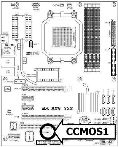
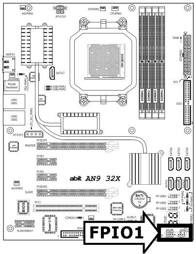
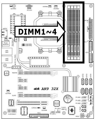
1.2 Motherboard Layout
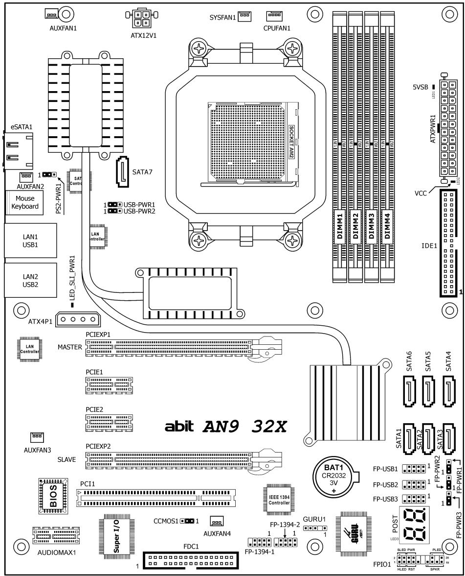
2. Hardware Setup
In this chapter we will elaborate all the information you need upon installing this motherboard to your computer system.
Always power off the computer and unplug the AC power cord before adding or removing any peripheral or component. Failing to so may cause severe damage to your motherboard and/or peripherals. Plug in the AC power cord only after you have carefully checked everything.
2.1 Choosing a Computer Chassis
- This motherboard carries an ATX form factor of 305 × 245 ~mm . Choose a chassis big enough to install this motherboard.
- As some features for this motherboard are implemented by cabling connectors on the motherboard to indicators and switches or buttons on the chassis, make sure your chassis supports all the features required.
- If there is possibility of adopting some more hard drives, make sure your chassis has sufficient power and space for them.
- Most chassis have alternatives for I/O shield located at the rear panel. Make sure the I/O shield of the chassis matches the I/O port configuration of this motherboard. You can find an I/O shield specifically designed for this motherboard in its package.
2.2 Installing Motherboard
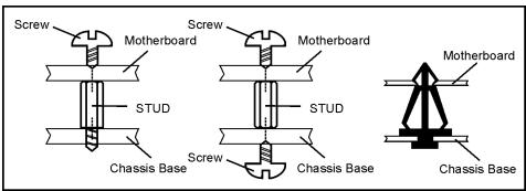
Most computer chassis have a base with many mounting holes to allow the motherboard to be securely attached, and at the same time, protected the system from short circuits. There are two ways to attach the motherboard to the chassis base:
- with studs,
- or with spacers
In principle, the best way to attach the board is with studs. Only if you are unable to do this should you attach the board with spacers.
Line up the holes on the board with the mounting holes on the chassis. If the holes line up and there are screw holes, you can attach the board with studs. If the holes line up and there are only slots, you can only attach with spacers. Take the tip of the spacers and insert them into the slots. After doing this to all the slots, you can slide the board into position aligned with slots. After the board has been positioned, check to make sure everything is OK before putting the chassis back on.

To install this motherboard:
- Locate all the screw holes on the motherboard and the chassis base.
- Place all the studs or spacers needed on the chassis base and have them tightened.
- Face the motherboard's I/O ports toward the chassis's rear panel.
- Line up all the motherboard's screw holes with those studs or spacers on the chassis.
- Install the motherboard with screws and have them tightened.
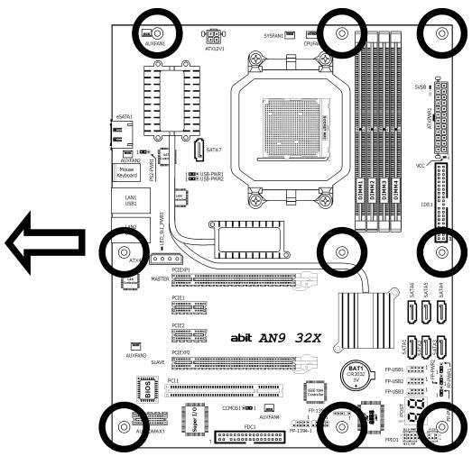
Face the chassis's rear panel.
To prevent shorting the PCB circuit, please REMOVE the metal studs or spacers if they are already fastened on the chassis base and are without mounting-holes on the motherboard to align with.
2.3 Checking Jumper Settings
For a 2-pin jumper, plug the jumper cap on both pins will make it CLOSE (SHORT). Remove the jumper cap, or plug it on either pin (reserved for future use) will leave it at OPEN position.
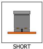
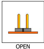
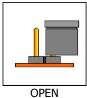
For 3-pin jumper, pin 1 2 or pin 2 3 can be shorted by plugging the jumper cap in.
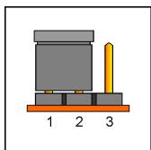
Pin 1~2 SHORT
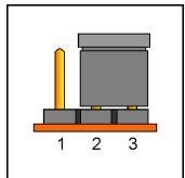
Pin 2~3 SHORT
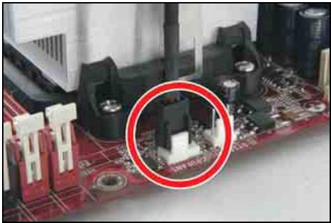
2.3.1 CMOS Memory Clearing Header and Backup Battery
The time to clear the CMOS memory occurs when (a) the CMOS data becomes corrupted, (b) you forgot the supervisor or user password preset in the BIOS menu, (c) you are unable to boot-up the system because the CPU ratio/clock was incorrectly set in the BIOS menu, or (d) whenever there is modification on the CPU or memory modules.
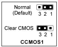
This header uses a jumper cap to clear the CMOS memory and have it reconfigured to the default values stored in BIOS.
- Pins 1 and 2 shorted (default): Normal operation.
- Pins 2 and 3 shorted: Clear CMOS memory.
To clear the CMOS memory and load in the default values:
- Power off the system and disconnect with AC power source.
- Set pin 2 and pin 3 shorted by the jumper cap. Wait for a few seconds. Set the jumper cap back to its default settings --- pin 1 and pin 2 shorted.
- Power on the system.
- For incorrect CPU ratio/clock settings in the BIOS, press
key to enter the BIOS setup menu right after powering on system. - Set the CPU operating speed back to its default or an appropriate value.
- Save and exit the BIOS setup menu.
CMOS Backup Battery:
An onboard battery saves the CMOS memory to keep the BIOS information stays on even after disconnected your system with power source. Nevertheless, this backup battery exhausts after some five years. Once the error message like "CMOS BATTERY HAS Failed" or "CMOS checksum error" displays on monitor, this backup battery is no longer functional and has to be renewed.
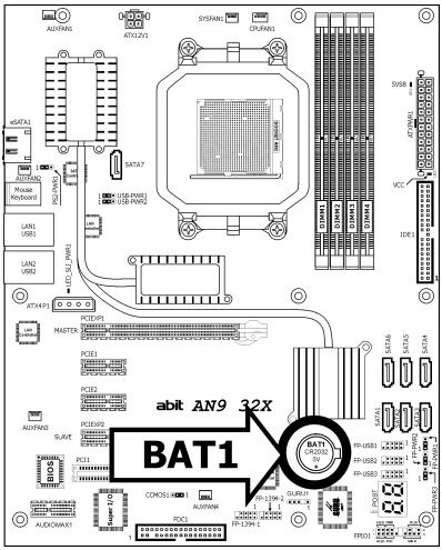
To renew the backup battery:
- Power off the system and disconnect with AC power source.
- Remove the exhausted battery.
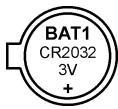
- Insert a new CR2032 or equivalent battery. Pay attention to its polarity. The "+" side is its positive polarity.
- Connect AC power source and power on the system.
- Enter the BIOS setup menu. Reconfigure the setup parameters if necessary.
CAUTION:
Danger of explosion may arise if the battery is incorrectly renewed.
Renew only with the same or equivalent type recommended by the battery manufacturer.
※ Dispose of used batteries according to the battery manufacturer's instructions.
2.3.2 Wake-up Headers
These headers use a jumper cap to enable/disable the wake-up function.
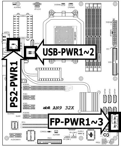
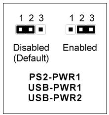
PS2-PWR1:
Pin 1-2 shorted (Default): Disable wake-up function support at Keyboard/Mouse port.
Pin 2-3 shorted: Enable wake-up function support at Keyboard/Mouse port.
USB-PWR1:
Pin 1-2 shorted (Default): Disable wake-up function support at USB1 port.
Pin 2-3 shorted: Enable wake-up function support at USB1 port.
USB-PWR2:
Pin 1-2 shorted (Default): Disable wake-up function support at USB2 port.
Pin 2-3 shorted: Enable wake-up function support at USB2 port
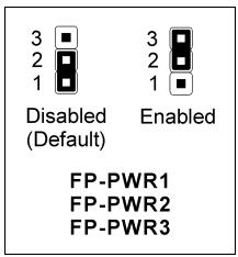
FP-PWR1:
Pin 1-2 shorted (Default): Disable wake-up function support at FP-USB1 port.
Pin 2-3 shorted: Enable wake-up function support at FP-USB1 port.
FP-PWR2:
Pin 1-2 shorted (Default): Disable wake-up function support at FP-USB2 port.
Pin 2-3 shorted: Enable wake-up function support at FP-USB2 port
FP-PWR3:
Pin 1-2 shorted (Default): Disable wake-up function support at FP-USB3 port.
Pin 2-3 shorted: Enable wake-up function support at FP-USB3 port
2.4 Connecting Chassis Components
2.4.1 ATX Power Connectors
These connectors provide the connection from an ATX power supply. As the plugs from the power supply fit in only one orientation, find the correct one and push firmly down into these connectors.
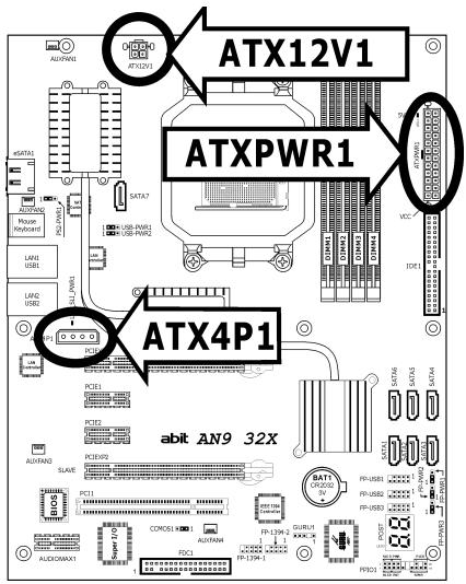
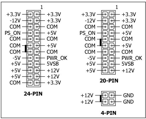
ATX 24-Pin Power Connector:
The power supply with 20-pin or 24-pin cables can both be connected to this 24-pin connector. Connect from pin-1 for either type. However, a 20-pin power supply may cause the system unstable or even unbootable for the sake of insufficient electricity. A minimum power of 300W or higher is recommended.
ATX 12V 4-Pin Power Connector:
This connector supplies power to CPU. The system will not start without connecting power to this one.
Auxiliary 12V Power Connector:
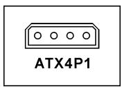
This connector provides an auxiliary power source for devices added on PCI Express slots.
2.4.2 Front Panel Switches & Indicators Headers
This header is used for connecting switches and LED indicators on the chassis front panel.
Watch the power LED pin position and orientation. The mark "+" align to the pin in the figure below stands for positive polarity for the LED connection. Please pay attention when connecting these headers. A wrong orientation will only cause the LED not lighting, but a wrong connection of the switches could cause system malfunction.
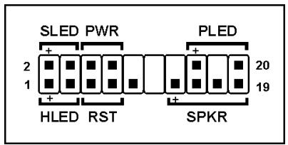
- HLED (Pin 1, 3):
Connects to the HDD LED cable of chassis front panel.
RST (Pin 5, 7):
Connects to the Reset Switch cable of chassis front panel.
SPKR (Pin 13, 15, 17, 19):
Connects to the System Speaker cable of chassis.
- SLED (Pin 2, 4):
Connects to the Suspend LED cable (if there is one) of chassis front panel.
PWR (Pin 6, 8):
Connects to the Power Switch cable of chassis front panel.
- PLED (Pin 16, 18, 20):
Connects to the Power LED cable of chassis front panel.
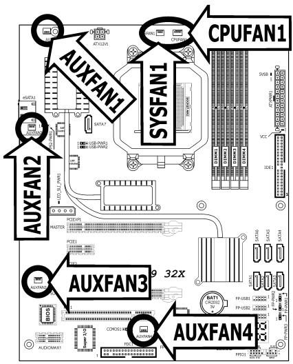
2.4.3 FAN Power Connectors
These connectors each provide power to the cooling fans installed in your system.
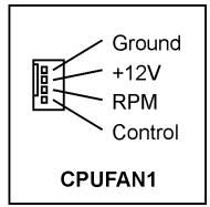
- CPUFAN1: CPU Fan Power Connector
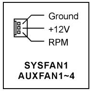
- SYSFAN1: System Fan Power Connector
- AUXFAN1~4: Auxiliary Fan Power Connector
These fan connectors are not jumpers. DO NOT place jumper caps on these connectors.
2.5 Installing Hardware
DO NOT scratch the motherboard when installing hardware. An accidentally scratch of a tiny surface-mount component may seriously damage the motherboard.
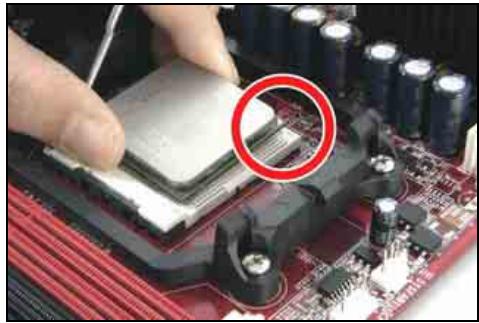
2.5.1 CPU Socket AM2
※ DO NOT touch or bend the delicate pins on the CPU whenever you are holding it.
The installation procedures vary with different types of CPU fan-and-heatsink assembly. The one shown here is served for DEMO only. For detailed information on how to install the one you bought, refer to its installation guidelines.
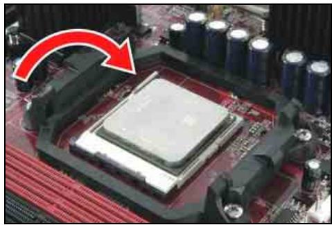
- Pull out the socket lever away from the socket and fully lift it up over 90-degree angle.
Locate and align the triangle mark with both the CPU and the socket body. Vertically place the CPU with its pin-side down into the socket.
Be careful to insert the CPU into the socket. The CPU only fits in one orientation with the socket. DO NOT force the CPU into the socket. - After placing the CPU into position, push the socket lever down into its locked position to secure the CPU. The lever clicks when it's locked into position.
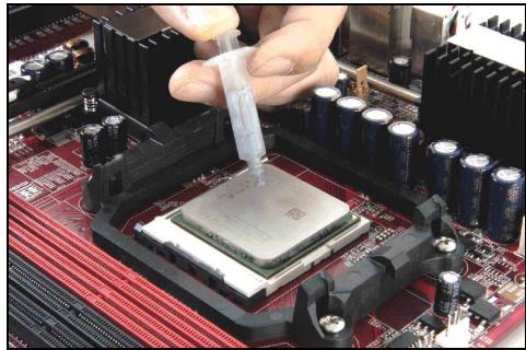
- The heatsink for CPU may have thermal interface material attached to its bottom. If not, applying a few squeeze of thermal paste to the CPU die will help to increase the contact.
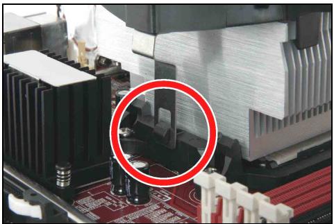
- Place the heatsink and fan assembly onto the retention frame. Match the heatsink clip with the socket mounting-lug. Hook the spring clip to the mounting-lug.
- On the other side, push the retention clip straight down to lock into the plastic lug on the retention frame.
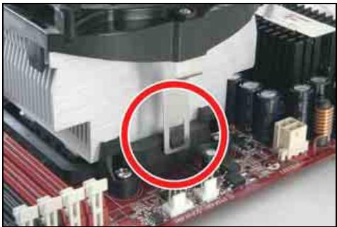
- Connect the CPU cooling fan power cable to the CPUFAN1 connector on this motherboard.
※ The "CPUFAN1" connector can be connected either with a 3-Pin or 4-Pin CPU cooling fan. For a 3-Pin connection, there will be no speed control available in the BIOS setup menu; the CPU fan will run at full speed.
Also, please watch out for the orientation when inserting 3-Pin plug into this 4-Pin fan connector.
The motherboard in this illustration is served for DEMO only, may not be the same type or model as the one described in this user's manual.
A higher fan speed will be helpful for better airflow and heat-dissipation. Nevertheless, stay alert to touch any heatsink since the high temperature generated by the working system is still possible.
2.5.2 DDR2 Memory Slots
This motherboard provides four 240-pin DIMM slots for Dual Channel DDR2 800 memory modules with memory expansion size up to 8GB.
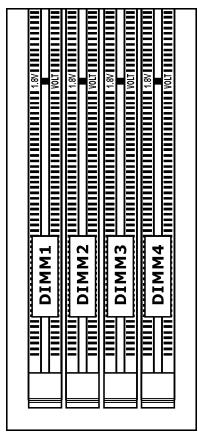
To reach the performance of Dual Channel DDR2, the following rules must be obeyed:
For a 2-DIMM dual-channel installation:
Populate DIMM modules of the same type and size on slots [DIMM1] + [DIMM2], or slots [DIMM3] + [DIMM4].
For a 4-DIMM dual-channel installation:
Populate 2 DIMM modules of the same type and size on slots [DIMM1] + [DIMM2], and another 2 DIMM modules of the same type and size on slots [DIMM3] + [DIMM4].
※ [DIMM1] and [DIMM2] slots are made of the same color.
[DIMM3] and [DIMM4] are made of another same color.
Usually there is no hardware or BIOS setup required after adding or removing memory modules, but you will have to clear the CMOS memory first if any memory module related problem occurs.
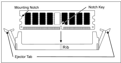
To install system memory:
- Power off the computer and unplug the AC power cord before installing or removing memory modules.
- Locate the DIMM slot on the board.
- Hold two edges of the DIMM module carefully, keep away from touching its connectors.
- Align the notch key on the module with the rib on the slot.
- Firmly press the module into the slots until the ejector tabs at both sides of the slot automatically snap into the mounting notch. Do not force the DIMM module in with extra force as the DIMM module only fits in one direction.
- To remove the DIMM modules, push the two ejector tabs on the slot outward simultaneously, and then pull out the DIMM module.
Static electricity can damage the electronic components of the computer or optional boards. Before starting these procedures, ensure that you are discharged of static electricity by touching a grounded metal object briefly.
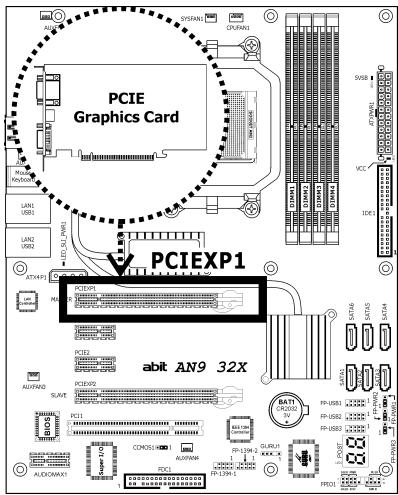
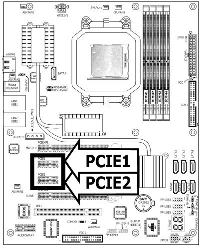
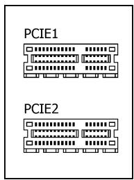
2.5.3 PCI Express X16 Add-on Slots (Install Graphics Card)
These slots support the connections of graphics cards that comply with PCI Express specifications. This motherboard provides dual PCI-Express X16 slots for one or two graphics cards installation:
One PCIE graphics card installation (Normal Mode):
Insert your PCIE graphics card into [PCIEXP1] slot.
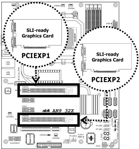
Two PCIE graphics cards installation (SLI Mode):
To install two SLI-ready graphics cards under SLI Mode, you will need to:
- Prepare two identical NVIDIA certified, SLI-ready PCI Express x16 graphics cards (the same model from the same manufacturer).
- Make sure the graphics card driver supports the NVIDIA SLI technology. Download the latest driver form NVIDIA website (www.nvidia.com).
- Make sure your power supply unit is sufficient to provide the minimum power required.
The following illustration is served for DEMO only. All the devices, including the motherboard, the graphics cards, the SLI Bridge Connector, or the SLI bracket, may not be exactly the same type, shape, or model as the one you bought.
- Insert two identical SLI-ready graphics cards into both PCIEXP1 and PCIEXP2 slots.
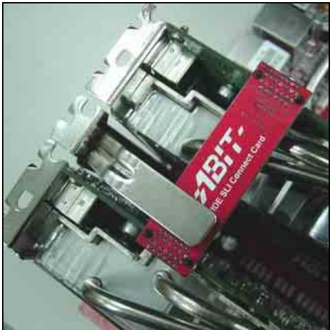
※ The NVIDIA SLI technology currently supports the Windows XP operating system only.
- Bridge connecting two graphics cards with the "SLI Connector Card" (fit in both direction).
Insert and secure the SLI supporting bracket.
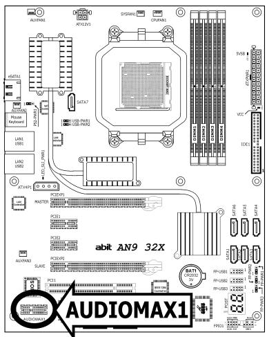
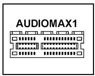
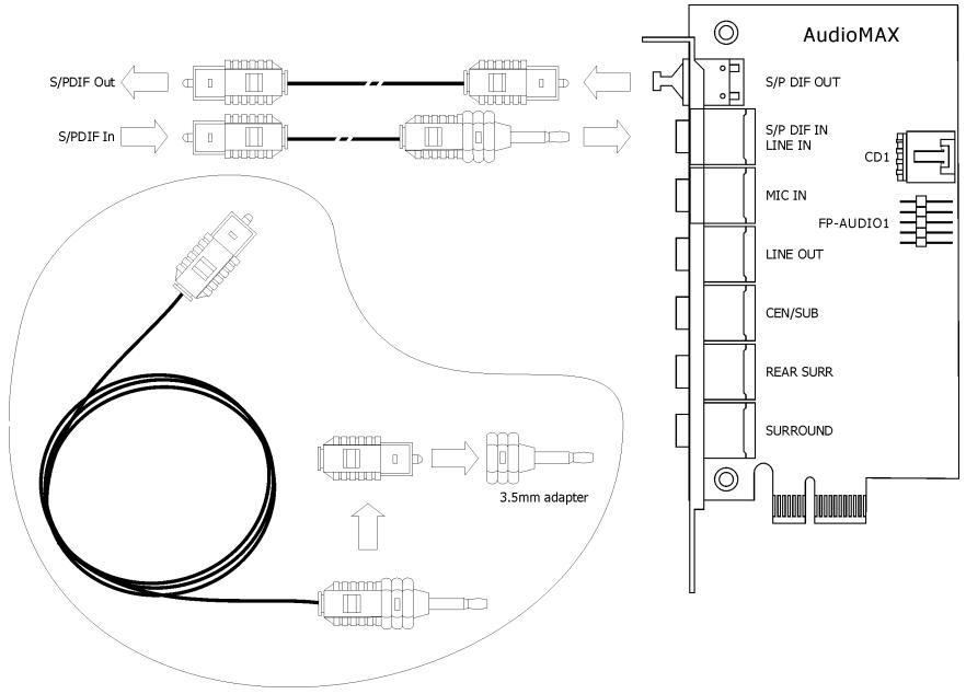
2.5.4 AudioMAX Connection Slot
This slot provides the audio input/output connection over the rear I/O part through an add-on daughter-card. Find your "AudioMAX" daughter-card and its driver in the motherboard package.
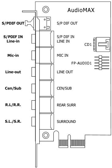
- S/PDIF Out: This connector provides an S/PDIF-Out connection through optical fiber to digital multimedia devices.
- S/PDIF In: This connector provides an S/PDIF-In connection through optical fiber to digital multimedia devices.
Line-In: Connects to the line out from external audio sources.
- Mic-In: Connects to the plug from external microphone.
- Line-Out: Connects to the front left and front right channel in the 7.1-channel or regular 2-channel audio system.
- Cen/Sub: Connects to the center and subwoofer channel in the 7.1-channel audio system.
- R.L./R.R. (Rear Left / Rear Right): Connects to the rear left and rear right channel in the 7.1-channel audio system.
- S.L./S.R. (Surround Left / Surround Right): Connects to the surround left and surround right channel in the 7.1-channel audio system.
- CD1: This connector connects to the audio output of internal CD-ROM drive or add-on card.
CD1

LGGR
- FP-AUDIO1: This header provides the connection to audio connector at front panel.
This header provides the front panel connection for HD (High Definition) Audio, yet for AC'97 Audio CODEC connection, you must carefully check the pin assignment before connecting from the front panel module. An incorrect connection may cause malfunction or even damage the motherboard.
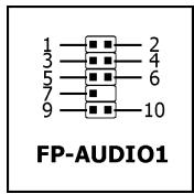
※ Please do not connect the "Ground" cable or "USB VCC" cable from the front panel module to the Pin 4 "AVCC" of this header.
| Pin | Pin Assignment (HD AUDIO) |
| 1 | MIC2_L |
| 2 | AGND |
| 3 | MIC2_R |
| 4 | AVCC |
| 5 | FRO-R |
| 6 | MIC2_JD |
| 7 | F_IO_SEN |
| 9 | FRO-L |
| 10 | LINE2_JD |
| Pin | Pin Assignment (AC'97 AUDIO) |
| 1 | MIC In |
| 2 | GND |
| 3 | MIC Power |
| 4 | NC |
| 5 | Line Out (R) |
| 6 | NC |
| 7 | NC |
| 9 | Line Out (L) |
| 10 | NC |
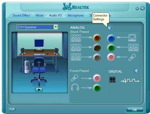
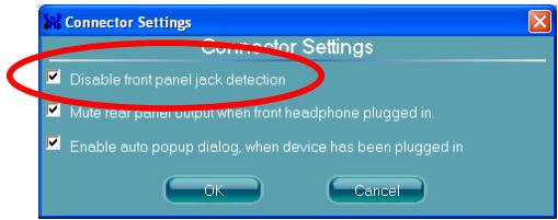
Driver Configuration for AC'97 audio connection:
The audio driver is originally configured to support HD Audio. For AC'97 audio connection, you may:
- Right-click the "Realtek HD Audio Manager" icon in system tray.

- Click "Audio I/O" tab, and then click "Connector Settings".
S/PDIF Connection:
In the motherboard package you can find one audio daughter-card and one optical-fiber cable.
S/PDIF Input Connection:
- Remove the rubber protection-cap. Attach one end of the optical cable with the 3.5mm Optical-to-Stereo adapter, and have it plugged into the [Line-In] jack on this daughter-card. (This jack is served for either optical or line input.)
- Connect the other end of the optical cable to the [Digital-Out] (SPDIF-Out) jack on your digital multimedia device.
S/PDIF Output Connection:
- Remove the rubber protection-cap. Plug one end of the optical cable into the [SPDIF-Out] jack on this daughter-card.
- Connect the other end of the optical cable to the [Digital-In] (SPDIF-In) jack on your digital multimedia device.
2.6 Connecting Peripheral Devices
2.6.1 Floppy and IDE Disk Drive Connectors
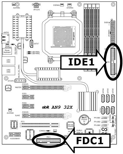
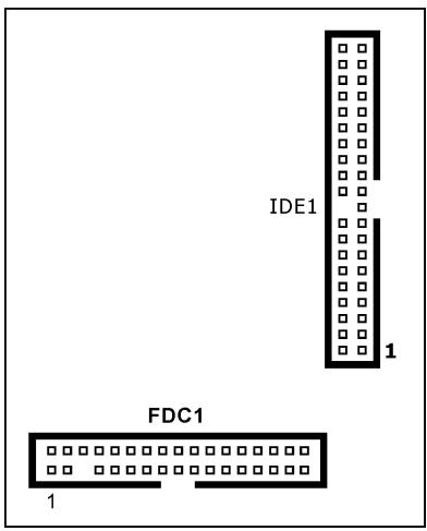
The FDC1 connector connects up to two floppy drives with a 34-wire, 2-connector floppy cable. Connect the single end at the longer length of ribbon cable to the FDC1 on the board, the two connectors on the other end to the floppy disk drives connector. Generally you need only one floppy disk drive in your system.
The red line on the ribbon cable must be aligned with pin-1 on both the FDC1 port and the floppy connector.
Each of the IDE port connects up to two IDE drives at Ultra ATA/100 mode by one 40-pin, 80-conductor, and 3-connector Ultra ATA/66 ribbon cables.
Connect the single end (blue connector) at the longer length of ribbon cable to the IDE port of this board, the other two ends (gray and black connector) at the shorter length of the ribbon cable to the connectors of your hard drives.
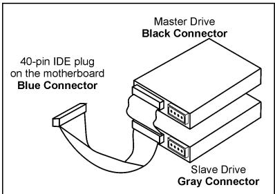
※ Make sure to configure the "Master" and "Slave" relation before connecting two drives by one single ribbon cable. The red line on the ribbon cable must be aligned with pin-1 on both the IDE port and the hard-drive connector.
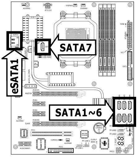
2.6.2 Serial ATA Connectors
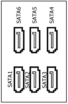
Each SATA connector serves as one single channel to connect one SATA device by a thin SATA cable.
- SATA1~SATA6: Available for RAID 0, RAID 1, RAID 0+1, RAID 5, or RAID 10 configuration by the utility "Intel Matrix Storage Manager".
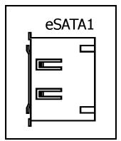
- SATA7、eSATA1: Available for RAID 0 or RAID 1 configuration by the utility "Sil3132 SATA RAID Driver".

To connect SATA device:
- Attach either end of the signal cable to the SATA connector on motherboard. Attach the other end to SATA device.
- Attach the SATA power cable to the SATA device and connect the other end from the power supply.
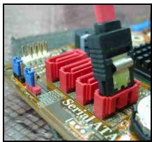
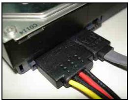
The motherboard in this illustration is served for DEMO only, may not be the same type or model as the one described in this user's manual.
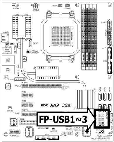
2.6.3 Additional USB 2.0 Port Headers
Besides the 4x USB 2.0 ports located at rear I/O part, this motherboard also features 3x more USB 2.0 headers onboard. Each header supports 2x additional USB 2.0 ports by connecting bracket or cable to the rear I/O panel or the front-mounted USB ports of your chassis.
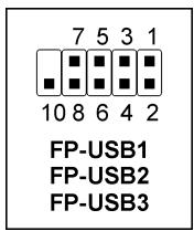
| Pin | Pin Assignment | Pin | Pin Assignment |
| 1 | VCC | 2 | VCC |
| 3 | Data0 - | 4 | Data1 - |
| 5 | Data0 + | 6 | Data1 + |
| 7 | Ground | 8 | Ground |
| 10 | NC |
※ Make sure the connecting cable bears the same pin assignment.
2.6.4 Additional IEEE1394 Port Headers
Each header supports 1x additional IEEE1394 port by connecting bracket or cable to the rear I/O panel or the front-mounted IEEE1394 port of your chassis.
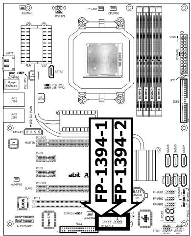
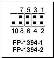
| Pin | Pin Assignment | Pin | Pin Assignment |
| 1 | TPA0 + | 2 | TPA0 - |
| 3 | Ground | 4 | Ground |
| 5 | TPB0 + | 6 | TPB0 - |
| 7 | +12V | 8 | +12V |
| 10 | Ground |
※ Make sure the connecting cable bears the same pin assignment.
2.6.5 PCI Express X1 Add-on Slots
These slots provide the connection of add-on cards that comply with PCI Express specifications.
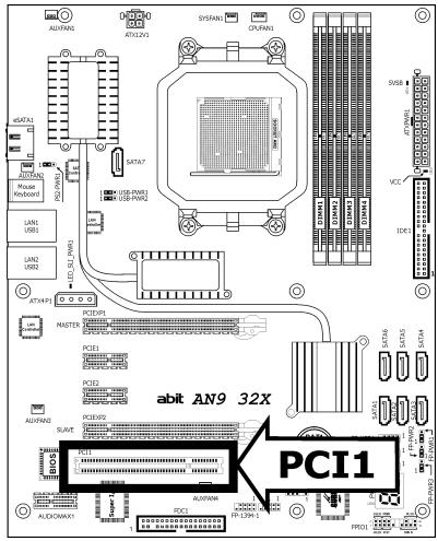
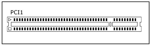
2.6.6 PCI Add-on Slot
This slot provides the connection of add-on cards that comply with PCI specifications.
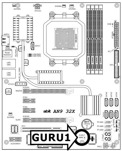
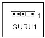
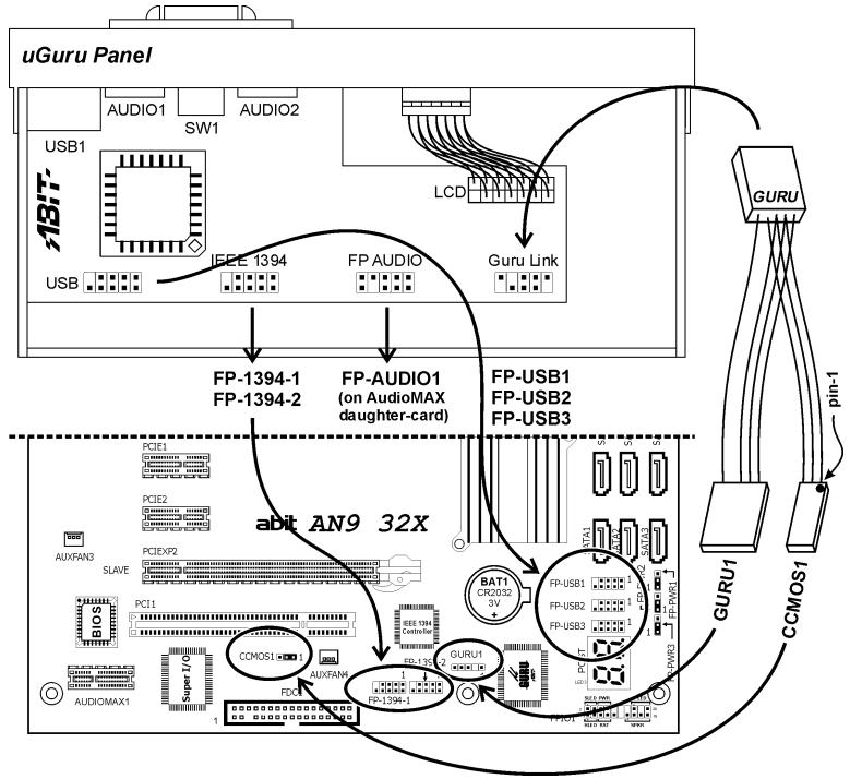
2.6.7 GURU Panel Connection Header
This header is reserved for connecting ABIT's exclusive GURU Panel. For more information, please refer to the included GURU Panel Installation Guide.
2.7 Onboard Status Display
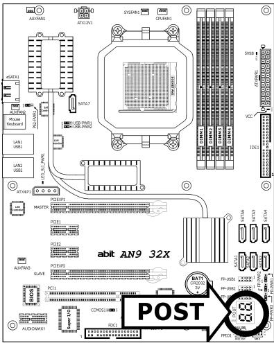
2.7.1 POST Code Displayer
This is an LED device to display the "POST" Code, the acronym for Power On Self Test. The computer will execute the POST action whenever you power on the computer. The POST process is controlled by the BIOS. It is used to detect the status of the computer's main components and peripherals. Each POST Code corresponds to different checkpoints that are also defined by the BIOS in advance. For example, "memory presence test" is an important checkpoint and its POST Code is "C1". When the BIOS execute any POST item, it will write the corresponding POST Code into the address 80h. If the POST passes, the BIOS will process the next POST item and write the next POST Code into the address 80h. If the POST fails, we can check the POST Code in address 80h to find out where the problem lies.
This LED device also displays the "POST" Code of AC2005, an "uGuru" chipset developed exclusively by Universal ABIT.
※ The decimal point lights up during the AC2005 POST action.

See Appendix for both AWARD and AC2005 POST Code definitions.
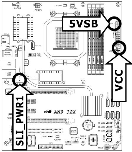
2.7.2 Power Source Indicators
These indicators work as a reminding device to display the power status of this motherboard with power source connected.
5VSB:
Lights On: Your ATX power supplier is connected with power source, and its power switch is on.
Lights Off: Your ATX power supplier is not connected with power source, or connected with power source but its power switch is off.
VCC:
Lights On: The system power is on.
Lights Off: The system power is off.
- SLI_PWR1:
Lights On: The system power is on.
Lights Off: The "ATX4P1" connector is connected with power source from your ATX power supplier.
2.8 Connecting I/O Devices
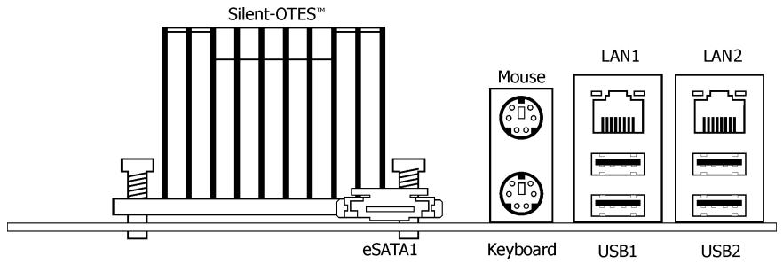
- Silent OTES™: The Silent OTES™ (Silent Outside Thermal Exhaust System) is a device specifically designed to silently cool the motherboard's North Bridge chipset. (Keep the area for outgoing heat wave open.)
- eSATA1: This connector supports the external SATA connection.
- Mouse: Connects to PS/2 mouse.
- Keyboard: Connects to PS/2 keyboard.
- LAN1/LAN2: Connects to Local Area Network.
- USB1/USB2: Connects to USB devices such as scanner, digital speakers, monitor, mouse, keyboard, hub, digital camera, joystick etc.
3. BIOS Setup
This motherboard provides a programmable EEPROM so that you can update the BIOS utility. The BIOS (Basic Input/Output System) is a program that deals with the basic level of communication between processor and peripherals. Use the BIOS Setup program only when installing motherboard, reconfiguring system, or prompted to "Run Setup". This chapter explains the Setup Utility of BIOS utility.
After powering up the system, the BIOS message appears on the screen, the memory count begins, and then the following message appears on the screen:
PRESS DEL TO ENTER SETUP
If this message disappears before you respond, restart the system by pressing <Ctrl> + <Alt> + <Del> keys, or by pressing the Reset button on computer chassis. Only when these two methods fair should you restart the system by powering it off and then back on.
After pressing <Del> key, the main menu screen appears.
After pressing <Del> key, the main menu screen appears.
| Phoenix - Award BIOS CMOS Setup Utility | |
| uGuru Utility | PnP/PCI Configurations |
| Standard CMOS Features | Load Fail-Safe Defaults |
| Advanced BIOS Features | Load Optimized Defaults |
| Advanced Chipset Features | Set Password |
| Integrated Peripherals | Save & Exit Setup |
| Power Management Setup | Exit Without Saving |
| Esc: Quit | ↓↑→← : Select Item |
| F10: Save & Exit Setup | (C51XE/MCP55-6A61JA1BC-00) |
| F6: Save PROFILE To BIOS | F7 : Load PROFILE From BIOS |
| Change CPU's Clock & Voltage | |
In order to increase system stability and performance, our engineering staff is constantly improving the BIOS menu. The BIOS setup screens and descriptions illustrated in this manual are for your reference only, and may not completely match with what you see on your screen.
3.1 μGuru™ Utility
There are two setup menus in this µGuru utility. You may switch between these two by clicking the left or right arrow key on keyboard:
3.1.1 OC Guru
| μGuru Utility V1.00C | ||
| OC Guru | ||
| AMD Athlon(tm) 64 X2 Dual Core Processor 3800+ Frequency : 2000MHz | Item Help ▶ | |
| SLI-Ready Memory | Disabled | |
| CPU Operating Speed | 2000(200) | |
| X - Multiplier Factor | x10.0 | |
| X - External Clock | Auto | |
| Voltages Control | Auto Detect | |
| X - CPU Core Voltage | 1.3500V | |
| X - DDR2 Voltage | 1.85 V | |
| X - NB 1.2V Voltage | 1.20 V | |
| X - NB PCIE 1.2V Voltage | 1.20 V | |
| X - SB 1.5V Voltage | 1.50 V | |
| X - HyperTransport Voltage | 1.20 V | |
| X - DDR2 Reference Voltage | -20 mv | |
| Power Cycle Statistics | Press Enter | |
| |←:Move Enter:Select +/-/PU/PD:Value | F10:Save ESC:Exit | |
Brand Name
This item displays the CPU model name installed on this motherboard.
Frequency
This item displays the processor speed of the CPU installed on this motherboard.
SLI-Ready Memory
This item allows you to select the SPD profile for SLI-Ready memory modules of EPP standard. The default setting is [Disabled]. You may determine the percentage of how much you would like to raise up according to the type of memory module you installed.
CPU Operating Speed
This item displays the CPU operating speed according to the type and speed of your CPU. You can also select the [User Define] option to enter the manual option.
User Define:
※ The wrong settings of the multiplier and external clock in certain circumstances may cause CPU damage. Setting the working frequency higher than the PCI chipset or processor specs, may cause abnormal memory module functioning, system hangs, hard disk drive data lose, abnormal functioning of the VGA card, or abnormal functioning with other add-on cards. Using non-specification settings for your CPU is not the intention of this explanation. These should be used for engineering testing, not for normal applications.
※ There will be no guaranty for the settings beyond specification. Any damage of any component on this motherboard or peripherals resulting therein is not our responsibility.
Multiplier Factor
This item displays the multiplier factor for the CPU installed.
External Clock
This item selects the external clock frequency. Due to the specification limit of the CPU you installed, the speed you set over its standard bus speed is supported, but not guaranteed.
Voltages Control
This option allows you to switch between the default and user-defined voltages. Leave this setting at default unless the current voltage setting cannot be detected or is not correct. The option "User Define" enables you to select the following voltages manually.
CPU Core Voltage
DDR2 Voltage
NB 1.2V Voltage
- NB PCIE 1.2V Voltage
- SB 1.5V Voltage
HyperTransport Voltage
DDR2 Reference Voltage
Power Cycle Statistics
Click
| μGuru Utility V1.00C | ||
| OC Guru | ||
| Power Cycle Statistics | ||
| PC Up Time | 0 Hours | Item Help ▶ |
| PC Up Time Total | 119 Hours | |
| PC Reset Button Cycles | 123 Cycles | |
| PC Power Cycles | 538 Cycles | |
| AC Power On Total Time | 288 Hours | |
| AC Power Cycles | 228 Cycles | |
| |←:Move Enter:Select +/-/PU/PD:Value F10:Save ESC:Exit | ||
These items display the power cycle statistics for each element.
3.1.2 ABIT EQ
Click right-arrow < > key to switch from OC Guru setup menu to ABIT EQ setup menu:
| μGuru Utility V1.00C | ||
| ABIT EQ | ||
| ABIT EQ Beep Control | Enabled | Item Help ▲ |
| ►Temperature Monitoring | Press Enter | |
| ►Voltage Monitoring | Press Enter | |
| ►Fan Speed Monitoring | Press Enter | |
| ►FanEQ Control | Press Enter | |
| {|←:Move Enter:Select +/-/PU/PD:Value F10:Save ESC:Exit | ||
ABIT EQ Beep Control
This item allows you to enable or disable ABIT EQ Beep Control function.

Temperature Monitoring
Click
| μGuru Utility V1.00C | |||||
| ABIT EQ | |||||
| Temperature Monitoring | |||||
| Reading | Shutdown Enable | Shutdown Temp. | Beep Enable | Beep Temp. | |
| (*)CPU Temperature | 34°C/93°F | (*) | 85°/185°F | (*) | 75°C/167°F |
| (*)System Temperature | 29°C/84°F | () | 65°C/149°F | (*) | 55°C/131°F |
| (*)PWM Temperature | 36°C/96°F | () | 90°C/194°F | (*) | 88°C/176°F |
| ↑→←:Move Enter:Select +/-/PU/PD:Value F10:Save ESC:Exit | |||||
CPU Temperature/System Temperature/PWM Temperature
These items display the temperature of CPU, System, and Power Module.
- Shutdown Enable
Use
- Shutdown Temp.
This items sets the temperature that will shutdown the system automatically in order to prevent system overheating.
- Beep Enable
Use
- Beep Temp.
This item selects the warning temperature limit.
※ The shutdown temperature must be set above the warning temperature.

Voltage Monitoring
Click
| μGuru Utility V1.00C | |||||
| ABIT EQ | |||||
| Voltage Monitoring | |||||
| Reading | Shutdown Enable | Beep Enable | High Limit | Low Limit | |
| (*)CPU Core Voltage | 1.40 | V(*) | (*) | 1.60 V | 0 V |
| (*)DDR2 Voltage | 1.80 | V() | (*) | 2.20 V | 1.50 V |
| (*)DDR2 VTT Voltage | 0.90 | V() | (*) | 1.10 V | 0.75 V |
| (*)HyperTransport Voltage | 1.20 | V() | (*) | 1.45 V | 0.95 V |
| (*)NB Voltage | 1.20 | V() | (*) | 1.45 V | 0.95 V |
| (*)CPU VDDA 2.5V Voltage | 2.50 | V() | (*) | 3.00 V | 2.00 V |
| (*)SB Voltage | 1.50 | V() | (*) | 1.00 V | 1.20 V |
| (*)ATX +12V (24-Pin Connector) | 12.00 | V() | (*) | 14.40 V | 9.60 V |
| (*)ATX +12V (4-Pin Connector) | 12.00 | V() | (*) | 14.40 V | 9.60 V |
| (*)ATX +5V | 5.00 | V() | (*) | 6.00 V | 4.00 V |
| (*)ATX +3.3V | 3.30 | V() | (*) | 3.95 V | 2.65 V |
| (*)ATX 5VSB | 5.00 | V() | (*) | 6.00 V | 4.00 V |
| |↑←:Move Enter:Select +/-/PU/PD:Value | F10:Save ESC:Exit | ||||
All Voltages
These items display the voltage of each element.
- Shutdown Enable
Use
- Beep Enable
Use
High/Low Limit
These items set the high and low voltage limit.
The value of high limit must be set above the one of low limit.

Fan Speed Monitoring
Click
| μGuru Utility V1.00C | ||||
| ABIT EQ | ||||
| Fan Speed Monitoring | ||||
| Reading | Shutdown Enable | Beep Enable | Low Limit | |
| (*)CPU FAN Speed | 7440 RPM | (*) | (*) | 300 RPM |
| ()SYS FAN Speed | N/A | () | () | 300 RPM |
| ()AUX1 FAN Speed | N/A | () | () | 300 RPM |
| ()AUX2 FAN Speed | N/A | () | () | 300 RPM |
| ()AUX3 FAN Speed | N/A | () | () | 300 RPM |
| ()AUX4 FAN Speed | N/A | () | () | 300 RPM |
| ↑|→←:Move Enter:Select +/-/PU/PD:Value | F10:Save | ESC:Exit | ||
CPU/SYS/AUX1~4 FAN Speed
These items display the speed of the fans connected to CPU, SYS, and AUX1~4 FAN headers.
- Shutdown Enable
Use
- Beep Enable
Use
Low Limit
These items set the low limit of fan speed.

FanEQ Control
| μGuru Utility V1.00C | ||
| ABIT EQ | ||
| FanEQ Control | ||
| CPU FanEQ Control | Press Enter | Item Help |
| SYS FanEQ Control | Press Enter | |
| AUX1 FanEQ Control | Press Enter | |
| AUX2 FanEQ Control | Press Enter | |
| AUX3 FanEQ Control | Press Enter | |
| AUX4 FanEQ Control | Press Enter | |
| ||→←:Move Enter:Select +/-/PU/PD:Value F10:Save ESC:Exit | ||
Click
| μGuru Utility V1.00C | ||
| ABIT EQ | ||
| CPU FanEQ Control | ||
| CPU FanEQ Control | Enabled | Item Help ▶□ |
| -Reference Temperature | CPU Temperature | |
| -Control Temperature High | 65°C/149°F | |
| -Control Temperature Low | 35°C/95°F | |
| -DC Fan Voltage High | 12.0 V | |
| -DC Fan Voltage Low | 8.0 V | |
| |←:Move Enter:Select +/-/PU/PD:Value F10:Save ESC:Exit | ||
CPU FanEQ Control
When set to [Enabled], these items control the CPU fan speed by the following setting combinations.
Reference Temperature
This item selects the reference point for taking temperature among the available options of CPU, SYS, and PWM Temperature, but there is only one "CPU Temperature" item to choose for the "CPU FanEQ Control".
- Control Temperature High/Low
These items set the high and low temperature limit that you want to do the fan speed control.
DC Fan Voltage High/Low
These items set the high and low voltage limit that you want to provide the fan with.
※ The value of high limit must be set above the one of low limit.
Click
| μGuru Utility V1.00C | ||
| ABIT EQ | ||
| SYS FanEQ Control | ||
| SYS FanEQ Control | Enabled | Item Help ▷□□ |
| -Reference Temperature | System Temperature | |
| -Control Temperature High | 40°C/104°F | |
| -Control Temperature Low | 30°C/86°F | |
| -DC Fan Voltage High | 12.0 V | |
| -DC Fan Voltage Low | 8.0 V | |
| ||→←:Move Enter:Select +/-/PU/PD:Value F10:Save ESC:Exit | ||
SYS FanEQ Control
When set to [Enabled], these items control the SYS fan speed by the following setting combinations.
Reference Temperature
This item selects the reference point for taking temperature among the available options of CPU, SYS, and PWM Temperature.
- Control Temperature High/Low
These items set the high and low temperature limit that you want to do the fan speed control.
DC Fan Voltage High/Low
These items set the high and low voltage limit that you want to provide the fan with.
The value of high limit must be set above the one of low limit.
Click
| μGuru Utility V1.00C | ||
| ABIT EQ | ||
| AUX1 FanEQ Control | ||
| AUX1 FanEQ Control | Enabled | Item Help ▶ ▶ |
| -Reference Temperature | System Temperature | |
| -Control Temperature High | 40°C/104°F | |
| -Control Temperature Low | 30°C/86°F | |
| -DC Fan Voltage High | 12.0 V | |
| -DC Fan Voltage Low | 8.0 V | |
| |←:Move Enter:Select +/-/PU/PD:Value F10:Save ESC:Exit | ||
AUX1 FanEQ Control AUX4 FanEQ Control
When set to [Enabled], these items control the AUX1~4 fan speed by the following setting combinations.
Reference Temperature
This item selects the reference point for taking temperature among the available options of CPU, SYS, and PWM Temperature.
- Control Temperature High/Low
These items set the high and low temperature limit that you want to do the fan speed control.
DC Fan Voltage High/Low
These items set the high and low voltage limit that you want to provide the fan with.
※ The value of high limit must be set above the one of low limit.
3.2 Standard CMOS Features
| Phoenix - Award BIOS CMOS Setup Utility Standard CMOS Features | ||
| Date (mm:dd:yy) | Mon. Jul 03 2006 | |
| Time (hh:mm:ss) | 12 : 34 : 56 | |
| IDE Channel 1 Master | None | |
| IDE Channel 1 Slave | None | |
| IDE Channel 3 Master | None | |
| IDE Channel 4 Master | None | |
| IDE Channel 5 Master | None | |
| IDE Channel 6 Master | None | |
| IDE Channel 7 Master | None | |
| IDE Channel 8 Master | None | |
| Drive A | 1.44M, 3.5 in. | |
| Drive B | None | |
| Floppy 3 Mode Support | Disabled | |
| Halt On | All, But keyboard | |
| Base Memory | 640K | |
| Extended Memory | 1046520K | |
| Total Memory | 1047552K | |
| |←:Move Enter:Select +/-/PU/PD:Value F10:Save ESC:Exit F1:GeneralHelp F5:Previous Values F6:Fail-Safe Defaults F7:Optimized Defaults | ||
Date (mm:dd:yy)
This item sets the date you specify (usually the current date) in the format of [Month], [Date], and [Year].
Time (hh:mm:ss)
This item sets the time you specify (usually the current time) in the format of [Hour], [Minute], and [Second].

IDE Channel 1 Master/Slave, IDE Channel 3 8 Master:
Click
| Phoenix - Award BIOS CMOS Setup Utility IDE Channel 1 Master | ||
| IDE HDD Auto-Detection | Press Enter | Item Help |
| IDE Channel 1 Master | Auto | |
| Access Mode | Auto | |
| Capacity | 0 MB | |
| Cylinder | 0 | |
| Head | 0 | |
| Precomp | 0 | |
| Landing Zone | 0 | |
| Sector | 0 | |
| ←:Move Enter:Select +/-/PU/PD:Value F10:Save ESC:Exit F1:GeneralHelp F5:Previous Values F6:Fail-Safe Defaults F7:Optimized Defaults | ||
IDE HDD Auto-Detection
This item allows you to detect the parameters of IDE drives by pressing
IDE Channel 1 Master/Slave, IDE Channel 3 8 Master
When set to [Auto], the BIOS will automatically check what kind of IDE drive you are using. If you want to define your own drive by yourself, set it to [Manual] and make sure you fully understand the meaning of the parameters. Please refer to the instruction manual provided by the device's manufacturer to get the setting right.
Access Mode
This item selects the mode to access your IDE devices. Leave this item at its default [Auto] setting to detect the access mode of your HDD automatically.
Capacity
This item displays the approximate capacity of the disk drive. Usually the size is slightly greater than the size of a formatted disk given by a disk-checking program.
Cylinder
This item configures the number of cylinders.
Head
This item configures the number of read/write heads.
Precomp
This item displays the number of cylinders at which to change the write timing.
Landing Zone
This item displays the number of cylinders specified as the landing zone for the read/write heads.
Sector
This item configures the number of sectors per track.

Back to Standard CMOS Features Setup Menu:
Drive A & Drive B
This item sets the type of floppy drives (usually only Drive A) installed.
Floppy 3 Mode Support
This item allows you to use "3 Mode Floppy Drive" in Japanese computer system by selecting drive A, B, or both. Leave this item at its default [Disabled] setting if you are not using this Japanese standard floppy drive.
Halt On
This item determines whether the system stops if an error is detected during system boot-up.
[All Errors]: The system-boot will stop whenever the BIOS detect a non-fatal error.
[No Errors]: The system-boot will not stop for any error detected.
[All, But Keyboard]: The system-boot will stop for all errors except a keyboard error.
[All, But Diskette]: The system-boot will stop for all errors except a diskette error.
[All, But Disk/Key]: The system-boot will stop for all errors except a diskette or keyboard error.
Base Memory
This item displays the amount of base memory installed in the system. The value of the base memory is typically 640K for system with 640K or more memory size installed on the motherboard.
Extended Memory
This item displays the amount of extended memory detected during system boot-up.
Total Memory
This item displays the total memory available in the system.
3.3 Advanced BIOS Features
| Phoenix - Award BIOS CMOS Setup Utility Advanced BIOS Features | ||
| Quick Power on Self Test | Enabled | Item Help |
| Hard Disk Boot Priority | Press Enter | |
| First Boot Device | Floppy | |
| Second Boot Device | Hard Disk | |
| Third Boot Device | CDROM | |
| Boot Other Device | Enabled | |
| Boot Up Floppy Seek | Disabled | |
| Boot Up NumLock Status | On | |
| Security Option | Setup | |
| MPS Version Ctrl For OS | 1.4 | |
| Full Screen Logo Show | Enabled | |
| ↔→←:Move Enter:Select +/-/PU/PD:Value F10:Save ESC:Exit F1:GeneralHelp F5:Previous Values F6:Fail-Safe Defaults F7:Optimized Defaults | ||
Quick Power On Self Test
When set to [Enabled], this item speeds up the Power On Self Test (POST) after powering on the system. The BIOS shorten or skip some check during the POST.
Hard Disk Boot Priority
This item selects the hard disks booting priority. By pressing
This item functions only when there is the option of [Hard Disk] in any one of the First/Second/Third Boot Device items.
First Boot Device / Second Boot Device / Third Boot Device / Boot Other Device
Select the drive to boot first, second and third in the [First Boot Device], [Second Boot Device], and [Third Boot Device] items respectively. The BIOS will boot the operating system according to the sequence of the drive selected. Set [Boot Other Device] to [Enabled] if you wish to boot from another device other than these three items.
Boot Up Floppy Seek
When the computer boots up, the BIOS detects if the system has a FDD or not. When this item is set to Enabled, if the BIOS detects no floppy drive, it will display a floppy disk drive error message. If this item is disabled, the BIOS will skip this test. The default setting is Disabled.
Boot Up NumLock Status
This item determines the default state of the numeric keypad at system booting up.
[On]: The numeric keypad functions as number keys.
[Off]: The numeric keypad functions as arrow keys.
Security Option
This item determines when the system will prompt for password - every time the system boots or only when it enters the BIOS setup.
[Setup]: The password is required only when accessing the BIOS Setup.
[System]: The password is required each time the computer boots up.
To disable security, select Set Password at main menu and then you will be asked to enter the password. Do not type anything and just press the
Don't forget your password. If you forget the password, you will have to open the computer case and clear all information in the CMOS before you can start up the system. But by doing this, you will have to reset all previously set options.
MPS Version Ctrl For OS
This item specifies which version of MPS (Multi-Processor Specification) this motherboard will use. Leave this item at its default setting.
Full Screen LOGO Show
This item determines if the full screen logo is shown when booting.
3.4 Advanced Chipset Features
| Phoenix - Award BIOS CMOS Setup Utility Advanced Chipset Features | ||
| K8<-->NB HT Speed | Auto | Item Help |
| K8<-->NB HT Width | Auto | |
| NB-->SB HT Speed | Auto | |
| NB<-->SB HT Width | Auto | |
| PCI Express bus(SB) | Hyperclk GPU | |
| NB<-->SB Reference clock | Auto | |
| PCI Express bus(NB) | Hyperclk GPU | |
| DRAM Configuration | Press Enter | |
| SSE/SSE2 Instructions | Enable | |
| System BIOS Cacheable | Enable | |
| NVIDIA GPU Ex | Disabled | |
| →←:Move Enter:Select +/-/PU/PD:Value F10:Save ESC:Exit F1:GeneralHelp F5:Previous Values F6:Fail-Safe Defaults F7:Optimized Defaults | ||
K8<->NB HT Speed:
This item selects the LDT Bus Frequency between CPU and NB.
K8<-->NB HT Width:
This item selects the LDT Bus Width between CPU and NB.
NB-->SB HT Speed:
This item selects NB to SB LDT Bus Frequency.
NB<->SB HT Width:
This item selects the LDT Bus Width between NB and SB.
PCI Express bus(SB)
This item adjusts the bus clock for "PCIEXP2" slot.
NB<- >SB Reference clock
This item adjusts the bus clock between NB and SB.
PCI Express bus(NB)
This item adjusts the bus clock for "PCIEXP1" slot.
DRAM Configuration:
Click
You may manually set the DRAM timing parameters through the following sub-items, or leave them at their default settings according to the SPD (Serial Presence Detect) data stored in the DRAM.
| Phoenix - Award BIOS CMOS Setup Utility DRAM Configuration | ||
| DRAM Timing Selectable | Auto | Item Help |
| X - DRAM Clock | DDR2 533 | |
| - DQS Timing Training | Skip DQS | |
| - CKE Base Power Down Mode | Enabled | |
| - CKE Base Power Down by | Channel | |
| - Memclock Tri-Stating | Disabled | |
| X - TwTr Command Delay | 2 Clocks | |
| X - Trfc0 for DIMM1 | 105 ns | |
| X - Trfc1 for DIMM2 | 75 ns | |
| X - Trfc2 for DIMM3 | 75 ns | |
| X - Trfc3 for DIMM4 | 75 ns | |
| X - Write Recovery Time(Twr) | 4 Clocks | |
| X - Precharge Time(Trtp) | 2 Clocks | |
| X - Row Cycle Time(Trc) | 17 Clocks | |
| X - RAS2CAS R/W Delay(Trcd) | 4 Clocks | |
| X - RAS to RAS Delay(Trrd) | 2 Clocks | |
| X - Row Precharge Time(Trp) | 4 Clocks | |
| X - Min. RAS Act-Time(Tras) | 12 Clocks | |
| Memory Hole Remapping | Enabled | |
| DRAM ECC Enable | Disabled | |
| X - DRAM MCE Enable | Disabled | |
| X - Chip-Kill Mode Enable | Disabled | |
| X - DRAM ECC Redirection | Disabled | |
| X - DRAM Scrub Rate | Disabled | |
| X - L2 Cache Scrub Rate | Disabled | |
| X - DCache Scrub Rate | Disabled | |
| Auto Optimize Bottom IO | Enabled | |
| X - [31:24] IO Space | F0 | |
| ←→:Move Enter:Select +/-/PU/PD:Value F10:Save ESC:Exit F1:GeneralHelp F5:Previous Values F6:Fail-Safe Defaults F7:Optimized Defaults | ||

Back to Advanced Chipset Features Setup Menu:
SSE/SSE2 Instructions
This item allows you to Enable or Disable the SSE/SSE2 (Streaming SIMD Extensions) instruction set.
System BIOS Cacheable
This item enables or disables caching the system BIOS for faster execution.
NVIDIA GPU Ex
Stands for "GPU Extra Performance". Enable this item to work for certain NVIDIA SLI graphics cards with certain driver version, but only minor performance will be expected. Leave this item at its default setting (Disabled).
3.5 Integrated Peripherals
| Phoenix - Award BIOS CMOS Setup Utility Integrated Peripherals | ||
| ►OnChip IDE/RAID Function | Press Enter | Item Help |
| Init Display First | PCIEXP1 | |
| OnChip USB | V1.1+V2.0 | |
| - USB Keyboard Support | OS | |
| - USB Mouse Support | OS | |
| OnChip Audio Controller | Auto | |
| OnChip LAN1 Controller | Auto | |
| OnChip LAN2 Controller | Auto | |
| Onboard LAN Boot ROM | Disabled | |
| Onboard FDD Controller | Enabled | |
| Onboard SATA Controller | Enabled | |
| - Onboard SATA Mode | IDE | |
| - SATA Option ROM | Enabled | |
| Onboard 1394 Controller | Enabled | |
| ↔→←:Move Enter:Select +/-/PU/PD:Value F10:Save ESC:Exit F1:GeneralHelp F5:Previous Values F6:Fail-Safe Defaults F7:Optimized Defaults | ||

OnChip IDE/RAID Function
Click
| Phoenix - Award BIOS CMOS Setup Utility OnChip IDE/RAID Function | |
| IDE Function Setup Press Enter RAID Configuration Press Enter | Item Help |
| Move Enter:Select +/-/PU/PD:Value F10:Save ESC:Exit F1:GeneralHelp F5:Previous Values F6:Fail-Safe Defaults F7:Optimized Defaults | |

IDE Function Setup:
Click
| Phoenix - Award BIOS CMOS Setup Utility IDE Function Setup | ||
| IDE 1 Controller | Enabled | Item Help |
| IDE DMA transfer access | Enabled | |
| IDE HDD Block Mode | Enabled | |
| Serial-ATA Controller | All Enabled | |
| ↔←:Move Enter:Select +/-/PU/PD:Value F10:Save ESC:Exit F1:GeneralHelp F5:Previous Values F6:Fail-Safe Defaults F7:Optimized Defaults | ||
IDE 1 Controller
This item allows you to enable or disable the IDE1 controller.
IDE DMA transfer access:
This item selects the DMA mode for devices connected through IDE channels.
IDE HDD Block Mode
This item enables or disables the IDE HDD Block Mode.
Serial-ATA Controller
This item enables or disables the on-chip SATA controller.

RAID Configuration:
Click
| Phoenix - Award BIOS CMOS Setup Utility RAID Configuration | ||
| RAID Function | Disabled | Item Help |
| X - Serial-ATA 1 RAID | Disabled | |
| X - Serial-ATA 2 RAID | Disabled | |
| X - Serial-ATA 3 RAID | Disabled | |
| X - Serial-ATA 4 RAID | Disabled | |
| X - Serial-ATA 5 RAID | Disabled | |
| X - Serial-ATA 6 RAID | Disabled | |
| X - OnChip SATA Boot ROM | Enabled | |
| ↔→←:Move Enter:Select +/-/PU/PD:Value F10:Save ESC:Exit F1:GeneralHelp F5:Previous Values F6:Fail-Safe Defaults F7:Optimized Defaults | ||
RAID Function
This item allows you to enable or disable the RAID function for Serial-ATA 1~6 ports.
Serial-ATA 1 RAID Serial-ATA 6 RAID
This item allows you to enable or disable the RAID function for each of the Serial-ATA 1~6 port individually.
- OnChip SATA Boot ROM
This item allows you to use the boot ROM of OnChip SATA to boot up system.

Back to Integrated Peripherals Setup Menu:
Init Display First
This item selects which display slot to initialize first when the system boots.
OnChip USB
Select the type of USB controller. Three options are available: Disabled V1.1+V2.0 V1.1. The default setting is V1.1+V2.0. If you choose to disable this item, the "USB Keyboard Support" and "USB Mouse Support" items will not be available to select in Integrated Peripherals menu.
USB Keyboard Support
Select [BIOS] for the legacy operating system (such as DOS) that does not support USB keyboard.
- USB Mouse Support
Select [BIOS] for the legacy operating system (such as DOS) that does not support USB mouse.
OnChip Audio Controller
This option enables or disables the audio controller.
OnChip LAN1 Controller
This option enables or disables the LAN1 controller.
OnChip LAN2 Controller
This option enables or disables the LAN2 controller.
Onboard LAN Boot ROM
This item allows you to use the boot ROM (instead of a disk drive) to boot-up the system and access the local area network directly.
Onboard FDD Controller
Two options are available: Enabled and Disabled. The default setting is Enabled. You can enable or disable the onboard FDD controller.
Onboard SATA Controller
This item enables or disables the Onboard SATA controller.
- Onboard SATA Mode
This item determines the mode for Onboard Serial ATA.
[IDE]: The on-chip Serial ATA served as IDE mode.
[RAID]: The on-chip Serial ATA served as RAID mode.
- SATA Option ROM
This item allows you to use the boot ROM of onboard Serial ATA RAID to boot up system.
Onboard 1394 Controller
This option enables or disables the IEEE 1394 controller.
3.6 Power Management Setup
| Phoenix - Award BIOS CMOS Setup Utility Power Management Setup | ||
| ACPI Suspend Type | S3(Suspend-To-RAM) | Item Help |
| - USB Resume from S3 | Disabled | |
| Power Button Function | Instant-Off | |
| Wakeup by PME# of PCI | Enabled | |
| Wakeup by OnChip LAN | Enabled | |
| Wakeup by Alarm | Disabled | |
| X - Day (of Month) Alarm | 0 | |
| X - Time (hh:mm:ss) Alarm | 0:0:0 | |
| Cool'n'Quiet Technology | Auto | |
| Power On Function | Button Only | |
| X - KB Power On Password | Enter | |
| X - Hot Key Power On | Ctrl-F1 | |
| Restore on AC Power Loss | Power Off | |
| ↔←:Move Enter:Select +/-/PU/PD:Value F10:Save ESC:Exit F1:GeneralHelp F5:Previous Values F6:Fail-Safe Defaults F7:Optimized Defaults | ||
ACPI Suspend Type
This item selects the type of Suspend mode.
[S1(PowerOn-Suspend)]: Enables the Power On Suspend function.
[S3(Suspend-To-RAM)]: Enables the Suspend to RAM function.
USB Resume from S3
When set to [Enabled], this item allows you to use a USB device to wake up a system that is in the S3 (STR - Suspend To RAM) state. This item can be configured only if the item "ACPI Suspend Type" is set to [S3(STR)].
Power Button Function
This item selects the method of powering off your system:
[Delay 4 Sec.]: Pushing the power button for more than 4 seconds will power off the system. This will prevent the system from powering off in case you accidentally hit or pushed the power button.
[Instant-Off]: Pressing and then releasing the power button at once will immediately power off the system.
Wakeup by PME# of PCI
When set to [Enabled], access through the add-on PCI card can remotely wake up the system that was in Soft-Off condition. The PCI card must support the wake up function.
Wakeup by OnChip LAN
When set to [Enabled], you can remotely wake up a PC in Soft-Off condition via a LAN card that support the wake up function.
Wakeup by Alarm
When set to [Enabled], you can set the date and time you would like the Soft-Off PC to power-on in the "Date (of Month) Alarm" and "Time (hh:mm:ss) Alarm" items. However, if the system is being accessed by incoming calls or the network (Resume On Ring/LAN) prior to the date and time set in these items, the system will give priority to the incoming calls or network instead.
- Date (of Month) Alarm
[0]: This option power-on the system everyday according to the time set in the "Time (hh:mm:ss) Alarm" item.
[1-31]: This option selects a date you would like the system to power-on. The system will power-on on the date set, and the time set in the "Time (hh:mm:ss) Alarm" item.
Time (hh:mm:ss) Alarm
This item sets the time you would like the system to power-on.
Cool 'n' Quiet Technology:
This option enables or disables the AMD K8 cool and quiet function.
Power On Function
This item selects the way you want your system to power on.
[Password]: Use a password to power on the system, select this option then press
[Hot KEY]: Use any of the function keys between <F1> to <F12> to power on the system.
[Mouse Left]: Double click the mouse left button to power on the system.
[Mouse Right]: Double click the mouse right button to power on the system.
[Any KEY]: Use any keyboard keys to power on the system.
[Button Only]: Use only the power button to power on the system.
[Keyboard 98]: Use the power-on button on the "Keyboard 98" compatible keyboard to power on the system.
The mouse wake up function can only be used with the PS/2 mouse, not with the COM port or USB type. Some PS/2 mice cannot wake up the system because of compatible problems. If the specs of your keyboard are too old, it may fail to power on.
KB Power ON Password
This item sets the password required in order to power on your computer.
Do not forget your password, or you will have to clear the CMOS and reset all parameters in order to utilize this function again.
Hot Key Power ON
This item powers on the system by pressing
Restore on AC Power Loss
This item selects the system action after an AC power failure.
[Power Off]: When power returns after an AC power failure, the system's power remains off. You must press the Power button to power-on the system.
[Power On]: When power returns after an AC power failure, the system's power will be powered on automatically.
[Last State]: When power returns after an AC power failure, the system will return to the state where you left off before power failure occurs. If the system's power is off when AC power failure occurs, it will remain off when power returns. If the system's power is on when AC power failure occurs, the system will power-on when power returns.
3.7 PnP/PCI Configurations
| Phoenix - Award BIOS CMOS Setup Utility PnP/PCI Configurations | |
| Resources Controlled By X - IRQ Resources | Auto(ESCD) Press Enter |
| PCI/VGA Pallete Snoop | Disbaled |
| ** PCI Express relative items | ** |
| Maximum Payload Size | 4096 |
| |←:Move Enter:Select +/-/PU/PD:Value F10:Save ESC:Exit F1:GeneralHelp F5:Previous Values F6:Fail-Safe Defaults F7:Optimized Defaults | |
Resources Controlled By
This item configures all of the boot and Plug-and-Play compatible devices.
[Auto(ESCD)]: The system will automatically detect the settings.
[Manual]: Choose the specific IRQ resources in the "IRQ Resources" menu.
- IRQ Resources
Click
This item sets each system interrupt to either [PCI Device] or [Reserved].
| Phoenix - Award BIOS CMOS Setup Utility - IRQ Resources | ||
| IRQ-4 assigned to | Reserved | Item Help |
| IRQ-5 assigned to | PCI Device | |
| IRQ-7 assigned to | PCI Device | |
| IRQ-10 assigned to | PCI Device | |
| IRQ-11 assigned to | PCI Device | |
| ↓→←:Move Enter:Select +/-/PU/PD:Value F10:Save ESC:Exit F1:GeneralHelp F5:Previous Values F6:Fail-Safe Defaults F7:Optimized Defaults | ||

Back to PnP/PCI Configurations Setup Menu:
PCI/VGA Palette Snoop
This item determines whether the MPEG ISA/VESA VGA cards can work with PCI/VGA or not.
[Disabled]: MPEG ISA/VESA VGA cards do not work with PCI/VGA.
[Enabled]: MPEG ISA/VESA VGA cards work with PCI/VGA.
Maximum Payload Size
This item sets the maximum TLP payload size for the PCI Express devices.
3.8 Load Fail-Safe Defaults
This option loads the BIOS default values for the most stable, minimal-performance system operations.
3.9 Load Optimized Defaults
This option loads the BIOS default values that are factory settings for optimal-performance system operations.
3.10 Set Password
This option protects the BIOS configuration or restricts access to the computer itself.
3.11 Save & Exit Setup
This option saves your selections and exits the BIOS setup menu.
3.12 Exit Without Saving
This option exits the BIOS setup menu without saving any changes.
4. Driver & Utility CD
The "Driver & Utility CD" that came packed with this motherboard contains drivers, utilities and software applications required for its basic and advanced features.
Place the "Driver & Utility CD" into the CD-ROM drive in your system. The following installation auto-run screen appears. If not, browse the root directory of the CD-ROM via the File Manager, and double click the "AUTORUN" file.
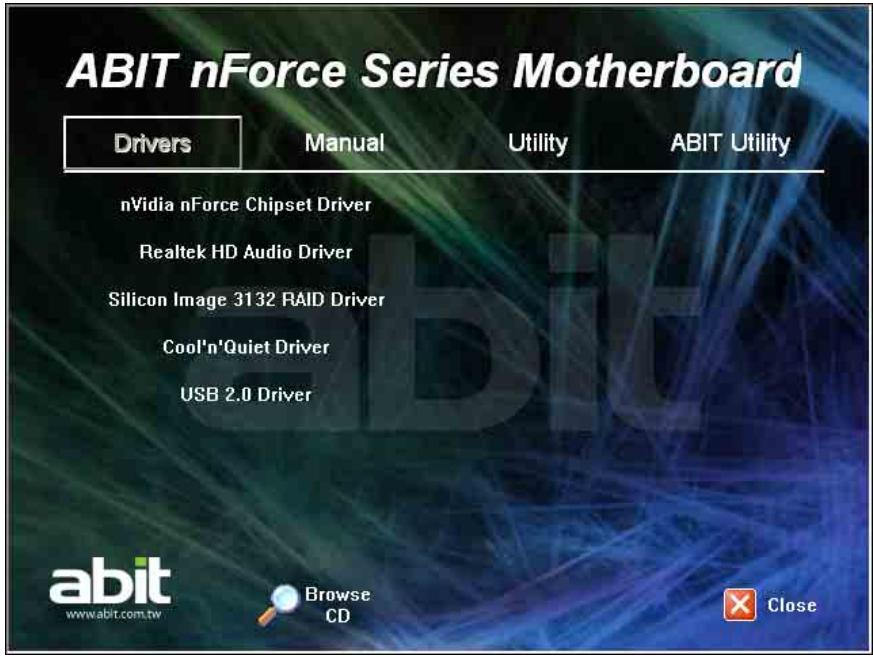
- [Drivers]: Click to enter the driver installation menu.
- [Manual]: Click to enter the user's manual menu.
- [Utility]: Click to enter the utilities installation menu.
- [ABIT Utility]: Click on this tab to enter the menu for installing utilities exclusively developed by ABIT.
- [Browse CD] : Click to browse the contents of this "Driver & Utility CD".
- [Close Close]: Click to exit this installation menu.
4.1 nVidia nForce Chipset Driver
To install this driver:
- Click on the [Drivers] tab in the installation menu screen.
- Click the [nVidia nForce Chipset Driver]. The following screen appears:
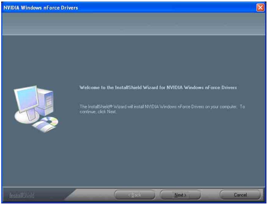
- Follow the prompts on the screen to complete installation.
- Restart the system for the driver to take effect.
※ Please install this nVidia nForce Chipset Driver first after having installed the Windows operating system.
4.2 Realtek HD Audio Driver
To install this driver:
- Click on the [Drivers] tab in the installation menu screen.
- Click the [Realtek HD Audio Driver] item. The following screen appears:
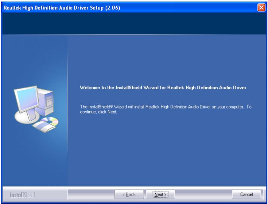
- Follow the prompts on the screen to complete installation.
- Restart the system for the driver to take effect.
Install this Driver after having installed the "AudioMAX" daughter-card.
4.3 Silicon Image 3132 RAID Driver
To install this driver:
- Click on the [Drivers] tab in the installation menu screen.
- Click the [Silicon Image 3132 RAID Driver] item. The following screen appears:
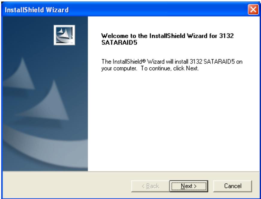
- Follow the prompts on the screen to complete installation.
- Restart the system for the driver to take effect.
4.4 Cool'n'Quiet Driver
To install this driver:
- Click on the [Drivers] tab in the installation menu screen.
- Click the [Cool'n'Quiet Driver] item. The following screen appears:
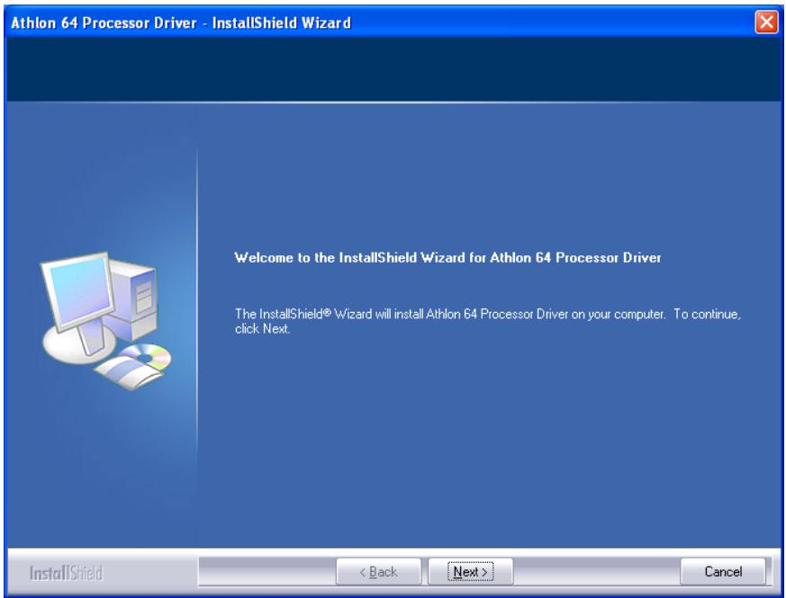
- Follow the prompts on the screen to complete installation.
-
Restart the system for the driver to take effect.
-
After the system restarted, open the "Power Options" from the control panel and choose the power scheme "Minimal Power Management" to enable Cool 'n' Quiet.
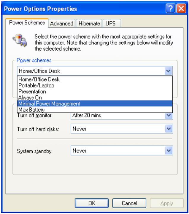
For Windows 2000 or ME system, an AMD Cool 'n' Quiet tab will appear under "Power Options" when the Cool 'n' Quiet software for Windows 2000 and ME is installed. This must be set to "Automatic Mode" for Cool 'n' Quiet to be enabled.
4.5 USB 2.0 Driver
There is no need to install this driver for Windows 2000 with Service Pack 4, Windows XP with Service Pack 1, or their later version.
4.6 ABIT μGuru Utility
The μGuru Utility combined with the optional Guru Clock allows you to access and select system performance of your system while playing games, listening music, browsing Internet or office applications in full screen with no need to stop or close the running application.
To install this utility:
- Click on the [ABIT Utility] tab in the installation menu screen.
- Click the [ABIT Guru] item. The following screen appears:

- Follow the prompts on the screen to complete installation.
- Restart the system for the driver to take effect.
4.7 NVRaid Floppy Disk
If you lost or damaged the SATA Driver Disk that came with the package, use the NVRaid Floppy Disk to create another one.
To install this utility:
- Click on the [ABIT Utility] tab in the installation menu screen.
- Click the [Generate NVRaid Floppy Disk[32bit]]. The following screen appears:
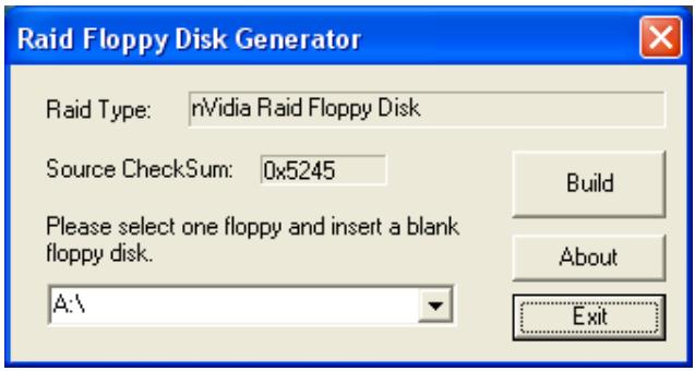
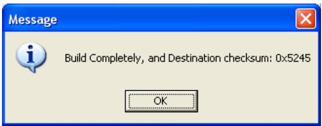
Insert one blank floppy disk to the selected floppy drive and click [Build].
- Click [OK] to finish building the SATA Driver Disk.
If you are using a windows 2000 operating system, please update your system to Service Pack 4 before starting to setup the NVIDIA RAID.
5. Appendix
5.1 POST Code Definitions
5.1.1 AWARD POST Code Definitions
| POST (hex) | Description |
| CF | Test CMOS R/W functionality |
| C0 | Early chipset initialization: -Disable shadow RAM -Disable L2 cache (socket 7 or below) -Program basic chipset registers |
| C1 | Detect memory -Auto-detection of DRAM size, type and ECC -Auto-detection of L2 cache (socket 7 or below) |
| C3 | Expand compressed BIOS code to DRAM |
| C5 | Call chipset hook to copy BIOS back to E000 & F000 shadow RAM |
| 01 | Expand the Xgroup codes locating in physical address 1000:0 |
| 03 | Initial Superio_Early_Init switch |
| 05 | 1. Blank out screen 2. Clear CMOS error flag |
| 07 | 1. Clear 8042 interface 2. Initialize 8042 self-test |
| 08 | 1. Test special keyboard controller for Winbond 977 series Super I/O chips 2. Enable keyboard interface |
| 0A | 1. Disable PS/2 mouse interface (optional) 2. Auto detect ports for keyboard & mouse followed by a port & interface swap (optional) 3. Reset keyboard for Winbond 977 series Super I/O chips |
| 0E | Test F000h segment shadow to see whether it is R/W-able or not. If test fails, keep beeping the speaker |
| 10 | Auto detect flash type to load appropriate flash R/W codes into the run time area in F000 for ESCD & DMI support |
| 12 | Use walking 1's algorithm to check out interface in CMOS circuitry. Also set real-time clock power status, and then check for override |
| 14 | Program chipset default values into chipset. Chipset default values are MODBINable by OEM customers |
| 16 | Initial onboard clock generator if Early_Init_Onboard_Generator is defined. See also POST 26. |
| 18 | Detect CPU information including brand, SMI type (Cyrix or Intel) and CPU level (586 or 686) |
| 1B | Initial interrupts vector table. If no special specified, all H/W interrupts are directed to SPURIOUS_INT_HDLR & S/W interrupts to SPURIOUSsoft_HDLR. |
| 1D | Initial EARLY PM_INIT switch |
| 1F | Load keyboard matrix (notebook platform) |
| 21 | HPM initialization (notebook platform) |
| 23 | 1. Check validity of RTC value: e.g. a value of 5Ah is an invalid value for RTC minute. 2. Load CMOS settings into BIOS stack. If CMOS checksum fails, use default value instead. |
| 24 | Prepare BIOS resource map for PCI & PnP use. If ESCD is valid, take into consideration of the ESCD's legacy information. |
| 25 | Early PCI Initialization: -Enumerate PCI bus number. -Assign memory & I/O resource -Search for a valid VGA device & VGA BIOS, and put it into C000:0 |
| 26 | 1. If Early_Init_Onboard_Generator is not defined Onboard clock generator initialization. Disable respective clock resource to empty PCI & DIMM slots. 2. Init onboard PWM 3. Init onboard H/W monitor devices |
| 27 | Initialize INT 09 buffer |
| 29 | 1. Program CPU internal MTRR (P6 & PII) for 0-640K memory address. 2. Initialize the APIC for Pentium class CPU. 3. Program early chipset according to CMOS setup. Example: onboard IDE controller. 4. Measure CPU speed. |
| 2B | Invoke Video BIOS |
| 2D | 1. Initialize double-byte language font (Optional) 2. Put information on screen display, including Award title, CPU type, CPU speed, full screen logo. |
| 33 | Reset keyboard if Early_SettKB is defined e.g. Winbond 977 series Super I/O chips. See also POST 63. |
| 35 | Test DMA Channel 0 |
| 37 | Test DMA Channel 1. |
| 39 | Test DMA page registers. |
| 3C | Test 8254 |
| 3E | Test 8259 interrupt mask bits for channel 1 |
| 40 | Test 8259 interrupt mask bits for channel 2 |
| 43 | Test 8259 functionality |
| 47 | Initialize EISA slot |
| 49 | 1. Calculate total memory by testing the last double word of each 64K page 2. Program writes allocation for AMD K5 CPU |
| 4E | 1. Program MTRR of M1 CPU 2. Initialize L2 cache for P6 class CPU & program CPU with proper cacheable range 3. Initialize the APIC for P6 class CPU 4. On MP platform, adjust the cacheable range to smaller one in case the cacheable ranges between each CPU are not identical |
| 50 | Initialize USB |
| 52 | Test all memory (clear all extended memory to 0) |
| 53 | Clear password according to H/W jumper (Optional) |
| 55 | Display number of processors (multi-processor platform) |
| 57 | Display PnP logo Early ISA PnP initialization -Assign CSN to every ISA PnP device |
| 59 | Initialize the combined Trend Anti-Virus code |
| 5B | (Optional Feature) Show message for entering AWDFLASH.EXE from FDD (optional) |
| 5D | 1. Initialize Init_Onboard_Super_IO 2. Initialize Init_OnboardAUDIO |
| 60 | Okay to enter Setup utility; i.e. not until this POST stage can users enter the CMOS setup utility |
| 63 | Reset keyboard if Early_SettKB is not defined |
| 65 | Initialize PS/2 Mouse |
| 67 | Prepare memory size information for function call: INT 15h ax=E820h |
| 69 | Turn on L2 cache |
| 6B | Program chipset registers according to items described in Setup & Auto-configuration table |
| 6D | 1. Assign resources to all ISA PnP devices 2. Auto assign ports to onboard COM ports if the corresponding item in Setup is set to "AUTO" |
| 6F | 1. Initialize floppy controller 2. Set up floppy related fields in 40:hardware |
| 75 | Detect & install all IDE devices: HDD, LS120, ZIP, CDROM ... |
| 76 | (Optional Feature) Enter AWDFLASH.EXE if: -AWDFLASH is found in floppy drive -ALT+F2 is pressed |
| 77 | Detect serial ports & parallel ports. |
| 7A | Detect & install co-processor |
| 7C | Init HDD write protect |
| 7F | Switch back to text mode if full screen logo is supported -If errors occur, report errors & wait for keys -If no errors occur or F1 key is pressed to continue: Clear EPA or customization logo |
| E&POST.ASM starts | |
| 82 | 1. Call chipset power management hook 2. Recover the text font used by EPA logo (not for full screen logo) 3. If password is set, ask for password |
| 83 | Save all data in stack back to CMOS |
| 84 | Initialize ISA PnP boot devices |
| 85 | 1. USB final Initialization 2. Switch screen back to text mode |
| 87 | NET PC: Build SYSID Structure |
| 89 | 1. Assign IRQs to PCI devices 2. Set up ACPI table at top of the memory. |
| 8B | 1. Invoke all ISA adapter ROMs 2. Invoke all PCI ROMs (except VGA) |
| 8D | 1. Enable/Disable Parity Check according to CMOS setup 2. APM Initialization |
| 8F | Clear noise of IRQs |
| 93 | Read HDD boot sector information for Trend Anti-Virus code |
| 94 | 1. Enable L2 cache 2. Program Daylight Saving 3. Program boot up speed 4. Chipset final initialization. 5. Power management final initialization 6. Clear screen & display summary table 7. Program K6 write allocation 8. Program P6 class write combining |
| 95 | Update keyboard LED & typematic rate |
| 96 | 1. Build MP table 2. Build & update ESCD 3. Set CMOS century to 20h or 19h 4. Load CMOS time into DOS timer tick 5. Build MSIRQ routing table |
| FF | Boot attempt (INT 19h) |
5.1.2 AC2005 POST Code Definitions
| POST (hex) | Description |
| Power On Sequence | |
| 8.1. | Start power on sequence |
| 8.2. | Enable ATX power supply |
| 8.3. | ATX power supply ready |
| 8.4. | DDR voltage ready |
| 8.5. | Setup PWM for CPU core voltage |
| 8.6. | Assert PWM for CPU core voltage |
| 8.7. | Check CPU core voltage |
| 8.8. | CPU core voltage ready |
| 8.9. | Initial clock generator IC |
| 8.A. | North Bridge chipset voltage ready |
| 8.B. | AGP voltage ready |
| 8.C. | 3VDUAL voltage ready |
| 8.D. | VDDA 2.5V voltage ready |
| 8.D. | GMCHVTT voltage ready |
| 8.E. | Check CPU fan speed |
| 8.F. | Assert all power ready |
| 9.0. | Complete μGuru initial processAWARD BIOS take over booting job |
| Power Off Sequence | |
| 9.1. | Start power off sequence |
| 9.2. | De-Assert all power |
| 9.3. | De-Assert power on |
| 9.4. | De-Assert LDT Bus power |
| 9.5. | De-Assert PWM for CPU core voltage |
| 9.6. | De-Assert CPU core voltage |
| 9.7. | Check CPU core voltage |
| 9.8. | De-Assert ATX power supply |
| 9.9. | Complete power off sequence |
| Others | |
| F.0. | Button reset |
| F.1. | SoftMenu reset |
| F.2. | Power on sequence timeout |
| F.3. | Power off sequence timeout |
5.2 Troubleshooting (How to Get Technical Support?)
5.2.1 Q & A
Q: Do I need to clear the CMOS before I use a new motherboard to assemble my new computer system?
A: Yes, we highly recommend that you clear the CMOS before installing a new motherboard. Please move the CMOS jumper from its default 1-2 position to 2-3 for a few seconds, and then back. When you boot up your system for the first time, follow the instructions in the user's manual to load the optimized defaults.
Q: If my system hangs when I update the BIOS or set the wrong CPU parameters, what should I do?
A: Whenever you update the BIOS or if the system hangs due to wrong CPU parameters setting, always clear CMOS jumper before booting up again.
Q: Why does the system fail to boot up again right after a mechanical power-off?
A: Please keep a 30-second interval between each mechanical power On/Off.
Q: Why does the system fail to boot up and nothing displays on the screen after I did some over-clocking or non-standard settings inside the BIOS?
A: It should not cause hardware or permanent damage to motherboard when BIOS settings were changed from default to over-clocking or non-standard status.
We suggest the following three troubleshooting methods to discharge CMOS data, recover the hardware default status, and then making the motherboard work again. There is no need to bother returning the motherboard to where you bought it from or go through an RMA process.
Step 1. Switch off the power supply unit and then switch it on again after one minute. If there is no power-switch on the power supply unit, disconnect its power cord for one minute and then reconnect.
Press and hold the key to enter the BIOS setup page to apply the correct settings.
If the situation remains the same, repeat the procedures in Step 1 for three times, or try Step 2.
Step 2. Switch off the power supply unit or disconnect the power cord. Open the chassis cover. Locate the CCMOS jumper near the button battery. Change the jumper position from default 1-2 to 2-3 for one minute to discharge the CMOS data, and then put it back to default 1-2 position.
Close the chassis and switch on the power supply unit or plug in the power cord. Press the power-on button to boot up system. If it works, hit key to enter the BIOS setup page to do the correct settings.
If the situation remains the same, try Step 3.
Step 3. The same procedure as Step 2, but while discharging the CMOS data, pull out the ATX power connectors from motherboard and remove the button battery during CMOS discharge.
Q: How to get a quick response for my request on technical support?
A: Please carry out a simple troubleshooting before sending "Technical Support Form":
System boot-up fails after the system had been assembled:
Check the motherboard's supporting specifications first to see if all the key components attached in your system can meet.
To do so, you may:
Remove all the unnecessary add-on devices (except the CPU, VGA card, DRAM, and Power Supply), and then reboot.
If the trouble still exists, try another VGA card of different brand/model to see if the system will start.
If the trouble still exists, try another memory module of different brand/model.
If the trouble still exists, try another CPU and Power Supply.
If the system runs successfully, shut it down and start re-installing the interface cards and devices that were previously installed in the system. Re-install and start the system one at a time until the system won't start.
Malfunction in the OS:
If the system hangs after resuming from S3 or some testing program, if the CPU cannot be recognized properly, if the display resolution mixed, or if a certain program cannot be executed, etc, you may:
Upgrade the motherboard's latest BIOS version.
Upgrade the add-on device's latest driver version.
Check if there is any conflict in the "Control Panel/System Properties".
Q: How to fill in the "Technical Support Form"?
A: To fill in this "Technical Support Form", please refer to the following instructions:
-
Subject: Type in the model name and the problem of your motherboard.
-
Region: Type in your country name.
E-mail: Type in your contact E-mail information. - First name: Type in your first name.
- Last name: Type in your last name.
Example 1: AA8XE and SCSI 29160 malfunction
Example 2: AA8XE boot fails, POST code AF
Example 3: AA8XE (system hang when S3 resume)
- Motherboard: Type in the model name and revision number of your motherboard.
Example: AA8XE REV: 1.00
BIOS Version: Type in the BIOS version of your motherboard. (You can find it on the screen during the POST sequence.)
- CPU: Type in the brand name and the speed (MHz) of your CPU. (Illustrate the over-clocking status if you had done so.)
Example: Intel 650 3.4GHz (OC FSB=220MHz)
- Memory brand: Type in the brand and model name of your memory module.
Example: Memory brand: Kingston (KVR533D2N4/1G)
Memory size: Type in the size of your memory module.
Example: 512M* 4PCS
Memory configuration: Type in the memory configuration in BIOS setting.
Example: Memory Timing: 2.5-3-3-7 @533MHz
- Graphics information: Note Graphics card's brand, model and driver version
- Graphics card: Type in the brand and model name of your graphics card.
Example: ATI RADEON X850 XT PE
- Graphics driver version: Type in the driver version of your graphics card
Example: Catalyst 5.12V
- Power supply maker: Type in the brand and model name of your power supply unit.
- Power supply wattage: Type in the power wattage of your power supply unit.
- Storage devices: Type in the brand and specifications of your HDD drive and quantity.
Specify if it was inserted on IDE (Master or Slave) or SATA ports, including the RAID allocation status.
Example 1: WD Caviar WD600 60GB (on IDE2 master), Maxtor DiamondMax 10 SATA 300GB (on SATA 3)
Example 2: Maxtor DiamondMax 10 SATA 300GB *2 (on SATA 3, SATA 4 RAID 1)
- Optical devices: Type in the brand and specifications of your optical drives and quantity. Specify if it was inserted on IDE (Master or Slave) or SATA ports.
- Other devices: Indicate which add-on cards or USB devices that you absolutely sure are related to the problem. If you cannot identify the problem's origin, indicate all the add-on cards or USB devices inserted on your system.
Example: AHA 29160 (on PCI 2), Sandisk Cruzer mini 256MB USB Flash-disk.
- Operating system: Indicate which OS and language version
Example: Microsoft Windows XP SP2, English version
Example: Microsoft Media Center Edition 2005, Korean version
- Problem description: Describe the problem of your system configuration. Indicate
the steps to duplicate problem if possible.
See the next page for a blank Technical Support Form, or visit our website to fill in the
form on line (http://www.ubit.com.tw/page/en/contact/technical.php).
Q. Is the motherboard dead? Do I need to return it to where I bought from or go through an RMA process?
A: After you had gone through the troubleshooting procedures, yet the problem still exists, or you find an evident damage on the motherboard. Please contact our RMA center.
(http://www2.abit.com.tw/page/en/contact/index.php?pFUN KEY=18000&pTITLE IMG)
5.2.2 Technical Support Form
| Region: | |
| E-mail: | |
| First name: | |
| Last Name: | |
| Subject: | |
| Motherboard: | |
| BIOS Version: | |
| CPU: | |
| Memory brand: | |
| Memory size: | |
| Memory configuration: | |
| Graphics card: | |
| Graphics driver version: | |
| Power supply maker: | |
| Power supply wattage: | |
| Storage devices: | |
| Optical devices: | |
| Other devices: | |
| Operating system: | |
| Problem description: |
5.2.3 Universal ABIT Contact Information
Taiwan Head Office
Universal ABIT Co., Ltd.
No. 323, Yang Guang St., Neihu,
Taipei, 114, Taiwan
Tel: 886-2-8751-3380
Fax: 886-2-8751-3381
Sales: sales@abit.com.tw
Marketing: market@abit.com.tw
North America, South America
Universal ABIT (USA) Corporation
2901 Bayview Drive,
Fremont, CA 94538, U.S.A.
Tel: 1-510-623-0500
Fax: 1-510-623-1092
Website: http://www.ubit-usa.com
Latin America: ventas@abit-usa.com
RMA Center: http://rma.abit-usa.com
UK, Ireland
Universal ABIT UK Corporation
Unit 3, 24-26 Boulton Road, Stevenage, Herts SG1 4QX, UK
Tel: 44-1438-228888
Fax: 44-1438-226333
Germany and Benelux (Belgium, Netherlands, Luxembourg), France, Italy, Spain, Portugal, Greece, Denmark, Norway, Sweden, Finland, Switzerland
Universal ABIT NL B.V.
Jan van Riebeeckweg 15, 5928LG, Venlo, The Netherlands
Tel: 31-77-3204428
Fax: 31-77-3204420
Austria, Czech, Romania, Bulgaria, Slovakia, Croatia, Bosnia, Serbia, Macedonia, Slovenia
Universal ABIT Austria Computer GmbH
Schmalbachstrasse 5, A-2201 Gerasdorf / Wien, Austria
Tel: 43-1-7346709
Fax: 43-1-7346713
Contact: office@abit-austria.at
Website: http://www.abit-austria.at
Shanghai
Universal ABIT (Shanghai) Co. Ltd.
FL 19 Xuhui Yuan BLOG NO.1089
ZhongShan s 2 RD, ShangHai 200030
The People's Republic of China
Tel: (86-21) 54102211
Fax: (86-21) 54104791
Website: http://www.abit.com.cn
Poland
Universal ABIT Poland (Rep. office)
Strzemogska 310/2, 54-432 Wroclaw
Tel: +48-71-718-12-39
Contact: Grzegorz Morgiel
Russia
Universal ABIT Russia (Rep. office)
Contact: info@abit.ru
Website: www.abit.ru
Turkey
Universal ABIT Turkey (Rep. office)
Tel: 90 532 211 6860
abit
UNIVERSAL ABIT Co., Ltd.
http://www.ubit.com.tw