USER MANUAL M1 INFORAD
natural_image
Line drawing of a connector housing with 'INFORAD' branding and mounting tabs (no text or symbols beyond label)
Quick Start-up guide
Guide de démarrage rapide
Guía rápida de utilización
Handleiding voor snelle start
GB
Quick start-up guide
INFORAD is designed to raise awareness of dangerous traffic zones and incite driver caution. Its purpose is to help you better observe the rules of the highway code and reduce the chance of accidents. INFORAD is not a detection device and does not interfere with Police doppler or laser radars. Its usage is perfectly legal.
FR
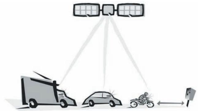
How does INFORAD work?
INFORAD uses the GPS (Global Positioning System) satellite network to constantly monitor your position and compare it with an onboard database of fixed speed cameras. This database is preloaded and will operate straight out of the box. Nevertheless, since speed camera locations may change from time to time, we advise you to register your device on our web site and update this database every so often using INFORAD MANAGER; an MS® Windows 98SE (or greater) application that connects you over the Internet to a central database maintained by INFORAD personnel.
natural_image
Diagram showing satellite coverage from a truck, car, and motorcyclist (no text or symbols)
When approaching a fixed speed camera, INFORAD will warn you visually 20 seconds ahead of time and 200 yards beyond it. These parameters are configurable by INFORAD MANAGER, which can be downloaded from the INFORAD web site: www.gpsinforad.com.
Quick start-up guide
Please read the following instructions carefully before installing your INFORAD.
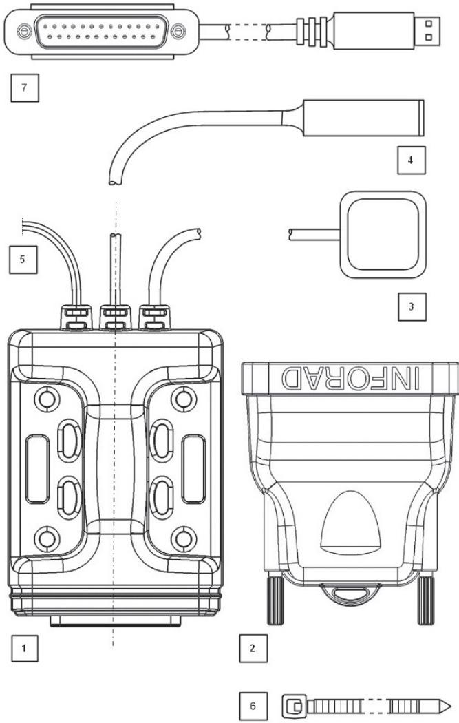
1 • Verify the contents of your package. Your box should contain:
- An INFORAD docking station (1) fitted with 3 electric cables (3, 4, 5)
• An INFORAD processor (2)
- An INFORAD USB cable designed for the processor (7)
• An INFORAD LED warning lamp (4)
- 6 plastic mounting strips (6)
2 • Downloading the INFORAD MANAGER PC application
INFORAD MANAGER enables you to a) modify certain parameters such as i) the approach and escape distance, ii) insert your own danger zones, iii) determine whether you have the latest version of the speed camera database and b) to register your device to receive database updates. It will also enable you to run diagnostic tests to ensure your device is functioning properly.
Go to the web site www.gpsinforad.com now and download INFORAD MANAGER.
Once downloaded to your PC's hard disk, install INFORAD MANAGER by clicking on the downloaded file and consult the help files on the main menu. The installation process will prompt you when to connect the INFORAD processor (2) to your PC via the supplied USB cable (7). During this installation phase you will need to register the serial number of your device from the one-years free access to database updates.
N.B. Please do not connect your INFORAD USB cable (7) to your PC before being prompted by the installation software.
3 • Installing INFORAD on your motor bike
INFORAD has been designed to enable maximum fitting flexibility on your vehicle. The docking station (1) and the fitted cables (3,4,5) are designed to remain permanently fitted. The INFORAD processor (2) detaches for PC database update and reconfiguring purposes.
(a) Installing the docking station:
The docking station (1) can be fitted by either tightening the supplied plastic strips (6), with screws (not supplied) or self-adhesive strip (not supplied). Be sure to choose a spot that will avoid accidents should the docking station come loose. We advise you consider the compartment beneath the rider's seat.
If you don't wish to mount the docking station permanently, you may use a self-adhesive strip. We strongly advise that you mount the device some where where vibrations won't shake it loose. We strongly recommend you avoid adhesives strips if you decide to attach the docking station to the outside of your bike.
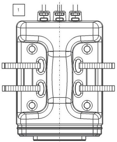
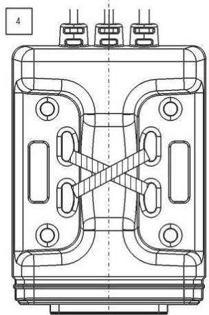
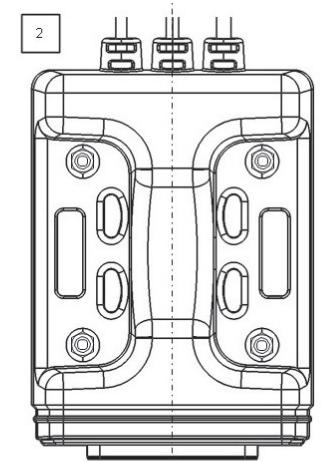
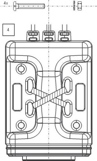
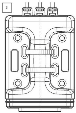
The following diagramme shows the various ways to mount the device :
(1,3,4): by tightening the plastic strips
(2) : with screws
natural_image
Technical line drawing of a mechanical component with symmetrical slots and mounting holes (no text or symbols)

natural_image
Technical line drawing of a mechanical component with symmetrical cutouts and mounting holes (no text or symbols)

natural_image
Technical line drawing of a mechanical component with symmetrical slots and mounting holes (no text or symbols)
natural_image
Technical line drawing of a mechanical component with symmetrical slots and mounting holes (no text or symbols)
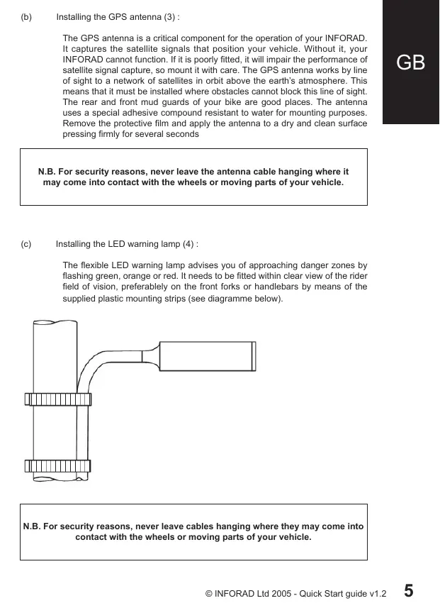
(b) Installing the GPS antenna (3):
The GPS antenna is a critical component for the operation of your INFORAD. It captures the satellite signals that position your vehicle. Without it, your INFORAD cannot function. If it is poorly fitted, it will impair the performance of satellite signal capture, so mount it with care. The GPS antenna works by line of sight to a network of satellites in orbit above the earth's atmosphere. This means that it must be installed where obstacles cannot block this line of sight. The rear and front mud guards of your bike are good places. The antenna uses a special adhesive compound resistant to water for mounting purposes. Remove the protective film and apply the antenna to a dry and clean surface pressing firmly for several seconds
N.B. For security reasons, never leave the antenna cable hanging where it may come into contact with the wheels or moving parts of your vehicle.
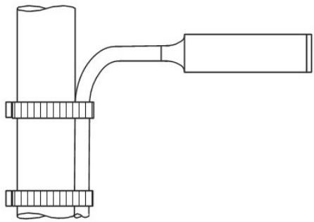
(c) Installing the LED warning lamp (4):
The flexible LED warning lamp advises you of approaching danger zones by flashing green, orange or red. It needs to be fitted within clear view of the rider field of vision, preferably on the front forks or handlebars by means of the supplied plastic mounting strips (see diagramme below).
natural_image
Pure mechanical assembly diagram showing a lever and base components without any text or symbols
N.B. For security reasons, never leave cables hanging where they may come into contact with the wheels or moving parts of your vehicle.
INFORAD requires an electrical power source of 5 to 24 V (400mW) provided through the cable (5). Fit the red cable to the positive and the black cable to the negative or earth.
IMPORTANT: In the event that you fit the power cable directly to the bike's battery, always disconnect the INFORAD processor to avoid discharging it.
4 • Starting your INFORAD
Once the INFORAD processor (2) is connected to the docking station (1), the LED lamp (4) will start flashing green. This tells you that the device is on and the process of 'satellite capture' has started. This process, depending on the line of sight with the satellite network, will take from between 1 and 5 minutes. The presence of tall buildings or tree cover will delay the satellite capture process. Once sufficient satellites have been captured (a minimum of 3 are required for operation), the LED lamp will emit a constant green light.
Visual warning signals
| Lamp colour | Meaning |
| Flashing green | Device not yet operational, searching for satellites. |
| Fixed green | INFORAD is operational. |
| Flashing orange | User defined danger zone (Point of Interest) approaching. |
| Fixed red | Warning – Approaching speed camera. |
| Flashing red | Warning – Speed exceeds authorised limit. |
Troubleshooting
1. The green light never stops flashing:
If your INFORAD's green light continues to flash for a sustained period of time (greater than 15 minutes), this indicates the unit cannot find the necessary number of satellites (3 minimum) and the following should be checked:
- When you plug your Inforad in for the very first time it can sometimes take a little longer to acquire satellites. Please be patient; it should not take more than 5 minutes at most.
- It is easier for your Inforad to first acquire satellites when your vehicle is stationary. A brief wait before setting off is all that is normally required.
- If the green light continues to flash, check that there is a clear line of sight between the antenna and the sky. Perhaps a saddle or luggage strapped to the back of your bike is blocking the signal.
- You may be too close to a tall building, tree coverage or some other obstacle that impairs the GPS signal. Make sure your Inforad is mounted to ensure a clear line of sight.
2. INFORAD MANAGER cannot detect the device
Before contacting Technical Support, we would ask that you read the following notice beforehand, as many issues can be quickly resolved:
- Please check that the INFORAD MANAGER has been correctly downloaded to your PC/Laptop/Notebook. If this has not been done or you cannot find the programme on your system, please refer to the 'Download & Register' section on the website www.gpsinforad.com and follow the on-screen instructions. If you have correctly downloaded please read on.
- INFORAD MANAGER needs to be connected to the INFORAD processor via your PC to perform all of its functions. Please ensure that the USB cable is properly inserted if INFORAD MANAGER has problems detecting the device. The INFORAD MANAGER 'Welcome' page gives you the status of the device's connection. If the software cannot detect or connect to your INFORAD, please try another USB 'com' port. If the device is recognised by INFORAD MANAGER, please read the next point.
N.B. INFORAD must be connected directly to your PC and not to a PC docking bay or USB hub.
-
Once the INFORAD MANAGER has detected the INFORAD processor, an Internet connection needs to be established to our web site. Please check that your 'Broadband' or 'Dial Up' connections are working properly. If you find that you do not have a connection, reinstate the connection. If your broadband or dial up connection is working please read the final point.
-
In some cases, antivirus or personal firewall software can impair downloads or registration and can even block connections from and to the INFORAD MANAGER application. Temporarily disable or lower the security settings of this software and attempt to reconnect again.
If the above points fail to resolve your problem please go to the 'Contact Technical Support' link which can be found in the 'About' section of your INFORAD MANAGER application. There you will complete a brief form describing your problem. When you submit the problem, detailed information about your configuration will be automatically transmitted to our technical support staff. We will investigate your problem and contact you as soon as possible.
On-line technical support
If you encounter installation or operational difficulties with your INFORAD, you may refer to the on-line help section in INFORAD MANAGER or consult the section Frequently Asked Questions (FAQ) on our web site: www.gpsinforad.com or send us an email to support@gpsinforad.com.
natural_image
Diagram showing satellite coverage from a truck, car, and motorcyclist (no text or symbols)
natural_image
Technical line drawing of a mechanical component with symmetrical slots and mounting holes (no text or symbols)
natural_image
Technical line drawing of a mechanical component with symmetrical cutouts and mounting holes (no text or symbols)

natural_image
Technical line drawing of a mechanical component with symmetrical slots and mounting holes (no text or symbols)

text_image
4x
4
natural_image
Pure mechanical assembly diagram showing a lever and shaft assembly without any text or symbols
natural_image
Diagram showing satellite coverage from a truck, car, and motorcyclist (no text or symbols)
(1,3,4): by tightening the plastic strips
(2) : with screws

natural_image
Technical line drawing of a mechanical component with symmetrical slots and mounting holes (no text or symbols)

natural_image
Technical line drawing of a mechanical component with symmetrical cutouts and mounting holes (no text or symbols)

natural_image
Technical line drawing of a mechanical component with symmetrical slots and mounting holes (no text or symbols)
text_image
4x
4
natural_image
Pure mechanical assembly diagram showing a lever and base components without any text or symbols
natural_image
Diagram showing satellite coverage from a truck, car, and motorcyclist (no text or symbols)
1 • Verify the contents of your package. Your box should contain:
natural_image
Technical line drawing of a mechanical component with symmetrical slots and mounting holes (no text or symbols)

natural_image
Technical line drawing of a mechanical component with symmetrical cutouts and mounting holes (no text or symbols)
natural_image
Technical line drawing of a mechanical component with symmetrical slots and mounting holes (no text or symbols)

text_image
4x
4
natural_image
Pure mechanical assembly diagram showing a lever and shaft assembly without any text or symbols
SiRF 12 channels capable of tracking 12 satellites simultaneously
Average acquisition time\*
Initialisation: \~3 mn, 38 s when cold and 8 s after warming up
Update time
1.0 s
Accuracy
Position 10 meters (10.9 yards) RMS - speed < 1 Km/h (0.62 mph)
Processor
RISC 32 bits ARM7 at 50MHz
Memory
Processor 128Kb - RAM 8Mb
Antenna
Active external
Alarm
Visual (6000 to 8000 mcd)
Power supply
Input: from 5V DC to 24V DC – (400 mW)
Weight
120 grammes (4.23 oz)
INFORAD
driving road safety ■ ■ ■
INFORAD Ltd
Unit L6, Smithstown Industrial Estate,
Shannon, County Clare,
Ireland
Tel: +353 61 719750
Fax: +353 61 719747
Contact: info@gpsinforad.com
Technical support: support@gpsinforad.com