B&W CASA SYSTEM - Audio System B&W - Free user manual and instructions
Find the device manual for free B&W CASA SYSTEM B&W in PDF.

User questions about B&W CASA SYSTEM B&W
0 question about this device. Answer the ones you know or ask your own.
Ask a new question about this device
Download the instructions for your Audio System in PDF format for free! Find your manual B&W CASA SYSTEM - B&W and take your electronic device back in hand. On this page are published all the documents necessary for the use of your device. B&W CASA SYSTEM by B&W.
USER MANUAL B&W CASA SYSTEM B&W
Disabling IR receiver 33
Ancillaries 33
T-pieces 33
Local Input 33
Remote Output module 33
Sub-zone Volume Module (AWM65/70) 33/34
CASA Interface 35
Cabling
RJ45 Connector Pin Assignment 36
4/4 Connector Pin Assignment 36
SYSTEM DESIGN
Designing 37/38
Loading Considerations 39/40
Adding...
Additional Speakers/Keypads 41
Local Sources 42
Remote Output 43
Additional Controllers 44
Sub-zones 45/46
Casa Interface 47
Two Identical source components 48
Two RC5 code controlled source components
48
Source with lower than average output 48
Home automation 48
INITIAL SYSTEM SET-UP
Remote 49
General Remarks 49
Clock Set-up 49
System Sources 49
Review 50
Tone Control and Balance 51
Zone Set-up 52
SYSTEM OPERATION
Reviewing System Sources 53
Timer 53
Sleep 53
Keypad controls 54
General Remarks 54
Switching on 54
OFF 54
VOL 54
MUTE 54
FAVSTN 54
RANDOM 54
and keys 55
and keys 55
LOCAL key 55
Source Keys 55
key 56
Remote control
STOP key 56
ALL OFF key 56
ZONE OFF key 56
Small Keypad controls
Switching on 57
ON/OFF key 57
Volume + key 57
key 57
Source keys 57
Using with...
Any source components 58
Any IR controlled source components 58
Tuners 58
CD players/Hard Disc Server 58
Cassette decks 58
DSS 58
Laserdisc and DVD players 58
Video recorders 58
Multiple User/Multiple Zones 59
Party Mode 59
Sub-zones 59
SAFETY INSTRUCTIONS
Read this page carefully to ensure safe operation.

CAUTION
To reduce the risk of electric shock, do not remove the cover or back panel. No user-serviceable parts inside. Refer servicing to qualified service personnel.
EXPLANATION OF GRAPHICAL SYMBOLS
The lightning flash with arrowhead symbol within an equilateral triangle is intended to alert you to the presence of uninsulated edangerous voltage within the product's enclosure that may be of sufficient magnitude to constitute an electric shock to persons.

The exclamation point within an equilateral triangle is intended to alert you to the presence of important operating and maintenance (servicing) instructions in the literature accompanying the equipment.
WARNING
TO PREVENT FIRE OR SHOCK HAZARD, DO NOT EXPOSE THIS EQUIPMENT TO RAIN OR MOISTURE.
OBSERVE ALL WARNINGS ON THE EQUIPMENT ITSELF. TO AVOID ELECTRICAL SHOCK, DO NOT OPEN THE CONTROLLER ENCLOSURE. THERE ARE NO USER SERVICEABLE PARTS INSIDE. REFER ALL SERVICE QUESTIONS TO AN AUTHORISED B&W DEALER.
TO PREVENT ELECTRIC SHOCK, DO NOT USE THIS (POLARISED) POWER PLUG WITH AN EXTENSION CORDRECEPTACLE OR OTHER OUTLET UNLESS THE BLADES CAN BE FULLY INSERTED TO PREVENT BLADE EXPOSURE.
ENSURE THAT THE VOLTAGE INDICATED ON THE CONTROLLER PANEL MATCHES THAT OF THE POWER SUPPLY.
THE EQUIPMENT MUST BE EARTHED (GROUNDED).
DO NOT INSERT OBJECTS THROUGH THE CONTROLLER VENTILATION HOLES.
VENTILATION - THE APPLIANCE SHOULD BE SITUATED SO
THAT ITS LOCATION OR POSITION DOES NOT INTERFERE WITH ITS PROPER VENTILATION:
A. FOR THE CONTROLLER: ENSURE AT LEAST 2 INCHES (50 MM) OF UNRESTRICTED AIR SPACE EITHER SIDE OF THE CONTROLLER AND 5 INCHES (125 MM) OF UNRESTRICTED AIR SPACE ABOVE THE CONTROLLER.
B. FOR THE SPEAKERS: ENSURE AT LEAST 2 INCHES (50 MM) OF UNRESTRICTED AIR SPACE IMMEDIATELY AROUND THE AREA OF THE REAR OF THE LOUDSPEAKER BAFFLE.
ENSURE SUFFICIENT SPACING BETWEEN CASA CONNECTION CABLES AND SINGLE INSULATED MAINS CABLING.
DO NOT RUN CASA CONNECTION CABLES AND TELECOMMUNICATIONS OR SINGLE INSULATED MAINS CABLING IN THE SAME TRUNKING.
USE CONNECTOR PLUGS AND SOCKETS WITH B&W APPROVED CASA COMPATIBLE EQUIPMENT ONLY.
DO NOT USE CONNECTOR PLUGS OR SOCKETS TO CONNECT TO COMPUTER OR TELEPHONY NETWORKS OR EQUIPMENT.
UK ONLY
Please follow these instructions for fitting a mains plug.
The wires in the mains plug are coloured with the following code:
$$ \text {B L U E} = \text {N e u t r a l} (N) $$
$$ B R O W N = \text {L i v e} (L) $$
GREEN and YELLOW = Earth (E)
As the colours of the mains lead in this appliance may not correspond with the colour markings identifying the terminals in your plug, proceed as follows:
The wire that is coloured BLUE must be connected to the terminal that is marked with the letter 'N' or
coloured black.
The wire that is coloured BROWN must be connected to the terminal that is marked with the letter 'L' or coloured red.
Neither of these wires may be connected to the Earth terminal.
The wire that is coloured GREEN and YELLOW must be connected to the terminal that is marked with the letter 'E', or by the earth symbol 1黄 or coloured GREEN or GREEN and YELLOW.
The 13 amp mains plug must be fitted with a 5 amp fuse.
IMPORTANT SAFEGUARDS
Read this page carefully to ensure safe operation.
Please read all the safety and operating instructions before operating this equipment. Adhere to all warnings on the equipment and in the installation/instruction manuals. Follow all the safety and operating instructions. These safety and operating instructions should be retained for future reference.
Power sources
The equipment should be connected to a power supply only of the type described in the installation/instruction manual or as marked on the equipment. For equipment intended to operate from battery power refer to the installation/instruction manual.
Power cord protection
Power supply cords should be routed so that they are not likely to be walked on or pinched by items placed over or against them. Particular attention should be paid to cords at plugs, convenience receptacles, and the point where they exit from the equipment. Never pull or stretch power cords.
Ventilation
Slots and openings in the equipment enclosure are provided for ventilation. To ensure reliable operation and to protect the equipment from overheating these openings must not be blocked or covered. The equipment should be situated so that its location and position does not interfere with proper ventilation. The equipment should not be used on a bed, sofa, rug, or similar surface that may block the ventilation openings. This equipment should not be placed in a built-in installation, such as a bookcase, cabinet or rack unless proper ventilation is provided or the manufacturer's instructions have been adhered to.
Carts and Stands
The equipment should be used only with a cart or stand that is recommended by the manufacturer.
Wall or Ceiling Mounting
The equipment should be mounted to a wall or ceiling only as recommended by the manufacturer.
Water and Moisture
The appliance should not be used near water - for example, near a bathtub, washbowl, kitchen sink, laundry tub, in a wet basement, or near a swimming pool and the like.
Temperature
The equipment may not function properly at extremely low, or freezing temperatures. The ideal ambient temperature is above +5^ (41^) .
Heat
The appliance should be situated away from heat sources such as radiators, heat registers, stoves, or other appliances (including amplifiers) that produce heat.
Electric shock
Care should be taken so that objects do not fall and liquid is not spilled into the enclosure through openings. If a metal
object such as a hair pin or needle comes into contact with the insides of this equipment, a dangerous electric shock may result. For families with children: never permit children to put anything, especially metal objects, inside this equipment.
Grounding or Polarisation
The equipment must be grounded (earthed). When using an extension power supply cord or a power supply cord other than that supplied, it should be 3-core, fitted with the appropriate moulded-on plug and carry safety approval appropriate to the country of use.
Cleaning
Use only a clean dry cloth. Do not use any solvents or liquids to clean the equipment.
Abnormal smell
If an abnormal smell or smoke is detected, immediately turn the power off and unplug the equipment from the wall outlet. Contact your supplier or service centre immediately.
Non-use Periods
The power cord should be unplugged from the wall outlet when the equipment is to be left unused for a long period of time.
Damage Requiring Service
The appliance should be serviced by qualified personnel when: the power supply cord or the plug has been damaged; or objects have fallen, or liquid has been spilled into the equipment; or the equipment has been exposed to rain; or the equipment does not appear to operate normally, or exhibits a marked change in performance; or the equipment has been dropped, or the enclosure damaged.
Servicing
The user should not attempt to service the equipment beyond that described in the installation/operating instructions. If servicing of any of the units making up the CASA System is required they should be returned for repair or replacement to:
B&W Loudspeakers Ltd, Meadow Road,
Worthing, BN11 2RX England
B&W Loudspeakers of America, 54 Concord
Street, North Reading, MA USA 01864-2699
INSTRUCTIONS DE SECURITE
CASA is a radically different multi-source, multi-room system. It is designed to offer a high quality, permanent audio installation, reliably and independently serving many rooms in one home through a simple yet powerful user-interface. For the installer it also offers simplicity of installation and reliability in use.
B&W Loudspeakers has an outstanding reputation for quality audio products. In designing its CASA multi-room system B&W set outstanding sound quality as an overriding priority.
Conventional multi-room systems use centralised power amplifiers to drive remote passive loudspeakers. This approach often limits the size and scope of a system and its architecture. Remote powered speakers are one obvious solution. However, the industry has avoided powered speaker systems because of the need to install both power and signal cabling to each speaker. There is an additional problem involved with powered speakers in needing to switch them on and off remotely through separate control wiring.
The CASA System side-steps these issues by using Active Speakers driven by remote DC power supplies in a central Controller. Output lines are driven in balanced form by independent amplifiers in the Controller. This form of working permits far longer cable runs than can generally be provided in domestic audio systems without loss of quality due to cable impedance effects or interference.
The connection requirement is for five signals between Active Speaker and Controller, namely two power, two signal and a ground. The adoption of Category 5 shielded RJ45 plugs and cables means the CASA System relies on just one proven connector type and cabling, familiar from the computer and telecommunications industries. This neatly satisfies all requirements for reliability and ease of installation.
The provision of DC power wiring to each Active Speaker gave the CASA design team an easy route down which to run data from infra red (IR) receivers in the speakers back to the central Controller. This IR data is carried at high frequencies and 'piggy backs' the power supply lines, eliminating the need for separate control conductors. Third-party IR remotes can also send back their IR data to the central Controller through this route.
Considerable effort has been put into designing the controlling software and the CASA Keypad Displays. The number of control keys has been reduced without putting limitations on flexibility or expandability. The design criterion for the operating software was intuitive, first-time use. Usability was also enhanced by taking the opportunity to provide a remote handset that could be used in place of a wall-mounted Keypad by communicating with the central controller through an IR receiver in a Active Speaker or Keypad.
The CASA Interface is a two-channel power supply that opens up the possibilities of using CASA through large buildings and widely distributed sites. The Interface can relieve the load on CASA Controllers and cost-effectively deliver extra power to system designs featuring many loudspeakers neatly by-passing loading issues. The open architecture of the CASA System allows for
endless possibilities of control via the RS-232 port. These connections allow integration with home automation products providing limitless configurability as defined by the home automation control system.
CASA is the first domestic audio system to use true, in-wall Active Speakers. Provision for multiple Controllers; a range of Active Speakers (some with active crossovers); additional power supplies; ancillary input and output modules and the division of zones into Sub-zones for the independent control of volume, all make CASA one of the most flexible, expandable, yet high quality multi-room systems available.
DEFINITIONS
The CASA multi-source, multi-room system is built around a central Controller driving Active Loudspeakers. Control over source switching and volume is by wall mounted Keypad/Display units (often referred to here simply as Keypads) and/or by hand-held Remote Controls.
Each Controller comprises of four independent digitally controlled pre-amplifiers selecting from four possible sources. Low-voltage power supplies feed four stereo outputs driving Active Loudspeakers. Each stereo output is under the control of a connected Keypad or IR remote control and comprises a CASA Zone.
The CASA Interface is an additional two-channel power supply to drive long cable runs and provide more power for elaborate systems. The CASA Interface can also be used to power CASA active speakers outside a CASA system to provide a superb sound quality installation. CASA Controllers can be linked one to another via the CANbus (Controller Area Network bus). All Controllers are shipped set as Slave Units. One Controller in a CANbus connected group must be designated a Master Controller during set-up - see section System Sources in the chapter Initial System Set-up.
The CASA System can relay its own IR (infra red) codes (CASA codes) from its own remote controls and from third-party remotes (Native codes). This enables CASA Controllers to pass native IR codes from one to another and out via either the Flood IR (a high power, wide area IR output) or electrical IR outputs to control connected third-party equipment from their own remote controls.
CASA Active Loudspeakers have their own on-board power amplification. Some use passive crossover networks for drive unit integration, others feature full active electronic crossovers. The first speakers (nearest the Controller) in a particular zone are called the Master speakers. More than one pair of speakers can be connected in a zone to receive the same signal (subject to certain operating limitations - see section Loading Considerations in the chapter System Design).
Subsidiary speakers may be connected to the buffered outputs (marked '2nd Speaker') on an ACM60 master speaker pair. They will operate at the same volume as the master speakers and are called 'Daisy chained' speakers.
The RJ45 sockets marked '2nd Speaker' on the AWM70, AWM65, have a function when the Sub-zone Module is added (or activated in the case of the AWM650 and ACM80), as does the 4/4 socket marked 'Volume'. When no Sub-zone Module is fitted or activated these connectors have no function. A subsidiary pair of speakers with their own volume control is termed a Sub-zone.
A Sub-zone may be connected beyond the master speakers only if the optional volume control modules are present or enabled on the master speakers. Certain operational limitations will apply:
The ACM60/65 cannot be used as a master speaker for a Sub-zone as it has no option to fit a Sub-zone Module. The AWM650 and ACM80 have the subzone fitted. To use please ensure the dip switch is in the correct position (See System Components, Sub-zone Volume Module section).
SYSTEM COMPONENTS
CONTROLLER (Figure 1a and 1b)
The CASA Controller is at the heart of the CASA multi-source, multi-room system. It contains four independent, digitally controlled preamplifiers, each of which can select from four available sources. In place of conventional power amplifiers the CASA Controller is equipped with low voltage power supplies feeding balanced output lines independently to four zones. The choice of low-voltage balanced working permits the Controller to drive cable lengths far in excess of that generally provided by domestic audio equipment. Each zone amplifier can drive its Active Speakers over anything up to 600 feet (200 metres) (including any 'daisy chained' loudspeakers). This is typically an order of magnitude higher than can be achieved with conventional speaker wiring without loss of quality.
Power outlets (one switched and one un-switched socket) are provided on the rear of the Controller. The Controller runs third-party equipment from a comprehensive but restricted number of reliable code sets based on the most popular equipment available. There is no means of adding codes for other equipment. Four line level inputs are provided with 'loop through' permitting the sources connected to the Controller to be used locally to it, in an independent high-quality audio/video system for example. An additional main zone line level Pre-Out is provided.
The CASA System provides a means by which other equipment can be controlled by transmission of locally received IR codes. Received at either Keypad or Active Speaker (AWM70, AWM65 and AWM650 only), the third-party IR codes are 'looped through' the Controller and transmitted both by the Flood IR on the Controller front panel, and by the IR output jack marked 'All'. IR output jacks marked 'Tun', 'CD', 'Aux 1' and 'Aux 2' drive 'stick-on' IR output devices (window emitters) that can be positioned over the IR receivers on equipment to be controlled. Two independent channels of IR information are available with Tun and Aux 1 carrying one channel and CD and Aux 2 the other. This means that two pieces of equipment of the same make and type (two Denon tuners for example) can be controlled independently.
A pair of RCA phono sockets, marked 'IR In' and 'IR Out', provide a 'loop through' facility for native IR codes to be passed from one Controller to another in multiple Controller installations. A single RCA phono socket is provided on the rear panel of the Controller for the control of equipment using RC5 codes. Each of the four zones is equipped with three RJ45 connectors, one to the Keypad and one each to the first stereo pair of speakers.Status LEDs (marked 'Left' and 'Right') show if power is being taken by a speaker to help diagnosis of installation problems.
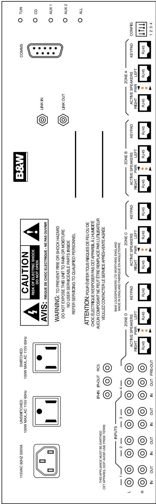
Figure 1a 110V model
Front panel indication is by LED and shows Zone On/Off, Zone receiving code and a Zone OK indicator, which illuminates when everything is fine. Each Controller preamplifier provides volume, tone and a balance control.
Overdriving is prevented by the speakers shutting off at maximum volume. In addition to a built-in current limiter each of the eight outputs (four zones, left and right) is protected by a polyswitch re-settable fuse. The Controller provides sufficient power for four 100W AWM70 speakers, eight 50W AWM65/AWM650 speakers or twenty 20W ACM60/ACM65/ACM80 speakers - see section Loading Considerations for further details.
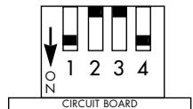
Controllers can be 'daisy chained' through the CANbus In/Out 3.5mm jack sockets marked 'Link In' and 'Link Out'. This high-speed serial link permits a seamless expansion of the CASA System to include up to eight Controllers. A 9-pin serial D connector (RS-232) permits in-field updates of the operating firmware held in flash EPROM - the Controller is switched into Software Upgrade mode by setting Switch 2 on the rear panel DIP switch in the Down position as shown in Figure 2a/b and subsequently power cycling the controller. This bi-directional serial port will also allow the CASA System to be integrated with other home automation products and offers the future possibility of computer software control.
1234
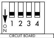
Figure 2a Normal

1234
Figure 2b Software upgrade mode
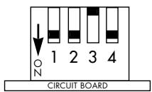
The front panel Flood IR emitter is a high power, wide coverage infra red output that can operate third-party equipment with native IR codes relayed through the CASA System. The Flood IR can be disabled by setting Switch 1 on the rear panel DIP switch in the Up position as shown in Figure 3a / b - see sub-sections Adding...Additional Controllers and Using With...Any IR controlled source component for further considerations.
1234
Figure 3a Flood IR enabled
1234
Figure 3b Flood IR disabled
Battery backed RAM is used to store all system and clock settings. See General Remarks section within the System Setup chapter.
240VAC 50Hz 500VA
UNSWITCHED
100W MAX.AC 240V 50Hz
SWITCHED
100W MAX.AC 240V 50Hz

Figure 1b 240V model - Mains, Unswitched and Switched sockets
KEYPAD/DISPLAY
(Figure 4)
The CASA integrated Keypad/Display fits in a double J-box. The Keypad incorporates an 8 character alphanumeric matrix display. A light sensor automatically adjusts display brightness to the ambient light conditions. An IR receiver is also incorporated. When the Keypad/Display is in a zone that is switched off, or if the CASA System is All off, the Keypad/Display can display either the present time (11:32 (for example)) or two dots (±) .
The time taken for the display to revert to showing the selected source after another command is issued is 3 seconds.
A Volume toggle key vol and 13 additional keys in three banks are featured. The top row of five keys provides source switching for four remote and one local source. Positions 1 and 2 always control the remote Tuner and CD, positions 3 and 4 can be customised to a number of remote sources. Position 5 provides source switching of the Local source only if a CASA Local Input Module is installed in the zone and connected to this Keypad.
The second bank of four keys 1< , >1 , << and >> performs various 'step up' and 'step down' functions depending on the source selected.
The bottom row of keys always features the OFF (Zone off/All off) and MUTE keys in positions 1 and 4 while positions 2 and 3 can be customised to work with source components having Favourite Station or Random Track selection features. Blank keys, FAV.STN and RANDOM keys and keys labelled with a range of alternative sources are supplied with every Keypad to permit customisation. When sources have been correctly set blank keys inserted into the Keypad produce no display response when pressed.
The case key in the top right of the display area can be used to display and set clock, alarm and sleep functions. The system Timer function can be used to set the system on and off times. In addition, a Sleep function can be set for 20 minute increments, up to 1 hour, that will turn off all sources including the Local source after that time has elapsed.
The rear panel of the Keypad/Display is provided with two RJ45 connectors (Next Keypad and Controller) through which the Keypad is connected to the CASA Controller and other Keypads. Keypads can be 'daisy chained' using these connections to provide additional Keypad control in any zone. There is a recommended maximum of three Keypads per zone.
A single 4/4 connector (Telephone Handset plug) carries serial data and clock information and is currently used only in conjunction with a Local Input module.
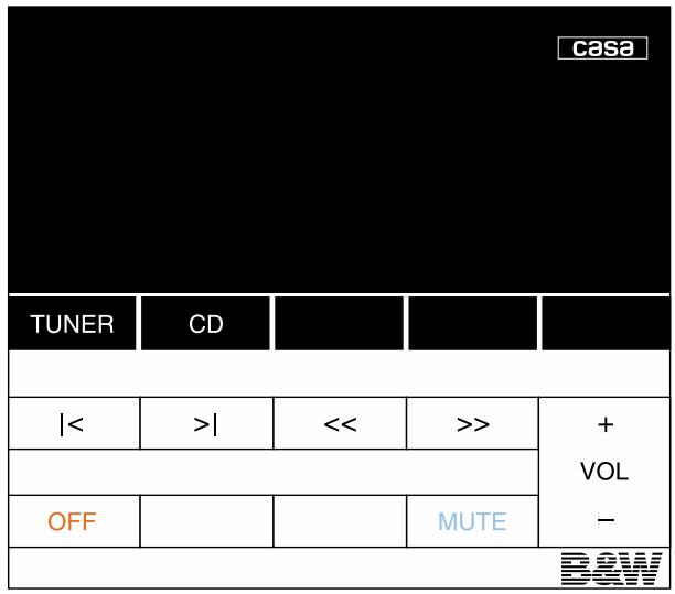
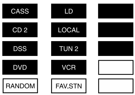
Figure 4 CASA Keypad/Display as shipped with optional key set to be fitted by installer.
SMALL KEYPAD
(Figure 5 and 6)
The CASA Small Keypad has been designed to be directly substituted for the CASA Keypad/Display in situations where a local input is not installed and where the display, timer and IR input features are not required. The Small Keypad fits in a single J-box. The Keypad has ten keys arranged in two banks of five. Four source buttons are featured.
The second group of three keys (<, > and >> ) performs various 'step up' and certain 'step down' functions depending on the source selected.
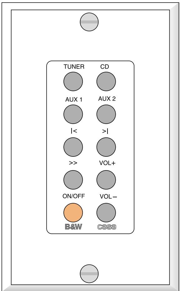
The paired keys to the bottom right offer volume up and volume down functions. There is an ON/OFF key to the lower left. Note: that the ON/OFF key has a slightly different mode of operation from the OFF key (Zone off/All off) on the Keypad/Display.
The rear of the Small Keypad is provided with two RJ45 connectors (Next Keypad and Controller) through which the Keypad is connected to the CASA Controller and other Keypads. Keypads can be 'daisy-chained' using these connections to provide additional Keypad control in any zone but there is a recommended maximum of three Keypad/Displays or 10 Small Keypads per zone.
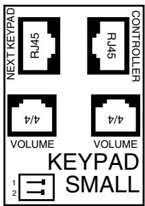
The two 4/4 connectors (Telephone Handset plug) are for connection to the volume connector on the speakers. One socket connects to the Left speaker and one to the Right. A dual DIP switch is used to configure the Small Keypad for use in any one of four Sub-zones A, B, C or D as shown in Figure 7.

Figure 5 - Key layout of Small Keypad
Figure 7a - Sub-Zone A

Figure 7b - Sub-Zone B

Figure 7c - Sub-Zone C

Figure 7d - Sub-Zone D
CASA REMOTE CONTROL
(Figure 8)
The CASA hand-held Remote control is an elegant and robust unit powered by two AAA batteries. It duplicates the functions of the Keypad keys though has an additional STOP key that puts any selected source into stop from any other mode (should this function be appropriate to the source selected). The Remote also features separate ZONE OFF and ALL OFF keys.
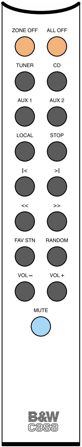
Figure 8
LOUDSPEAKERS
ACM™60
The ACM60 is a 20w, Active ceiling-mounted speaker using a 165 mm mid/bass driver with a 25 mm co-axially placed tweeter. No IR input is provided and there is no volume control option.
Two RJ45 connectors (Controller and 2nd Speaker) are provided which can be used to 'daisy chain' up to five pairs of ACM60s in any zone. See section Loading Considerations for further details.
ACM™65
The ACM^TM65 is a 2× 25w , Active ceiling mounted speaker using a 6.5-inch Kevlar mid/bass driver with a 1-inch coaxially placed tweeter. No IR input is provided and there is no volume control option.
Two RJ45 Connectors on the rear of the amplifier board enables stereo from mono capability.
If the speakers are overloaded the LED will flash red. If the system conversely is running into clipping the LED will emit a green flash.
ACM™80
The ACM^TM80 is a 2× 30w Active ceiling mounted speaker using a 8-inch Kevlar mid/bass driver with a 1-inch coaxially placed tweeter. No IR input is provided.
Three RJ45 connectors (Controller, 2nd Speaker, and local) are provided to connect to the controller and to use a Local source (in conjunction with the local Input module). The RJ45 socket market '2nd speaker' is used to provide a Subzone.
A single 4/4 connector marked volume is used when the speaker is configured to operate in subzone mode. If the speakers are overloaded the LED will flash red. If the system conversely is running into clipping the LED will emit a green flash.
The AWM65 is a wall-mounted 1 x 50w Active Speaker using a 6.5-inch Kevlar® mid/bass driver and a 1-inch aluminium dome tweeter. A high-quality passive crossover is used to integrate the mid/bass driver and tweeter.
An IR receiver/modulator is mounted in the bottom centre of the baffle. This receives IR codes from the remote control and transmits those codes back to the Controller by way of the power supply. An LED tell-tale flashes to show when an IR command has been received.
The AWM65 motherboard supports an option to add a volume controlled Sub-zone Module.
Three RJ45 connectors (Controller, 2nd Speaker and Local) are provided to connect to the Controller and to use a Local source (in conjunction with the Local Input module). The RJ45 socket marked '2nd speaker' is used to provide a Sub-zone when a Sub-zone Module is fitted.
A single 4/4 connector (Telephone Handset plug) marked 'Volume' is used in conjunction with the Sub-zone Volume Module mentioned above.
AWM™650
The AWM™650 is a wall-mounted 2 x 50w Active Speaker using a 6-inch Kevlar® mid/bass driver and a 1-inch aluminium dome tweeter. An active crossover is used to integrate the mid/bass driver and tweeter.
An IR receiver is mounted in the bottom centre of the baffle. This receives IR codes from the remote control and relays back to the controller by way of the power supply. An LED telltale flashes to show when an IR command has been received.
The AWM^TM650 motherboard includes a Sub-zone Module. This permits 'daisy chained' speakers on this output to be independently volume controlled.
Three RJ45 connectors (Controller, 2nd Speaker, and local) are provided to connect to the controller and to use a Local source (in conjunction with the local Input module). The RJ45 socket market '2nd speaker' is used to provide a Subzone.
A single 4/4 connector marked volume is used in conjunction with the Sub-zone Volume Module mentioned above.
If the speakers are overloaded the LED will flash red. If the system conversely is running into clipping the LED will emit a green flash.
AWM™70
The AWM70 is a wall-mounted 2 × 100w Active Speaker using a 7-inch Kevlar® mid/bass driver and a 1-inch aluminium dome tweeter. Two 100w channels of amplification are provided to power the HF and LF outputs of the active crossover. Amplifier power of this order requires substantial heatsinking which is provided both by a finned rear extrusion and the ribbed baffle itself.
The crossover has a damped 2nd-order network for the mid/bass unit and a 3rd-order slope for the tweeter. Active equalisation is used to enhance bass output and to perform drive unit correction and phase compensation giving smooth drive unit integration and good off-axis frequency response. The crossover also features overload and DC offset protection together with a power-on mute sequence (not using relays) that ensures power-up is free from clicks and bangs.
An IR receiver/modulator is mounted in the bottom centre of the baffle. This receives IR codes from the remote control and transmits those codes back to the Controller by way of the power supply. An LED tell-tale flashes to show when an IR command has been received.
The AWM70 motherboard supports an option to add a volume controlled Sub-zone Module. This will permit 'daisy chained' speakers on this output to be independently volume controlled.
Three RJ45 connectors (Controller, 2nd Speaker and Local) are provided to connect to the Controller and to use a Local source (in conjunction with the Local Input module). The RJ45 socket marked '2nd speaker' is used to provide a Sub-zone when a Sub-zone Module is fitted.
A single 4/4 connector (Telephone Handset plug) marked 'Volume' is used in conjunction with the Sub-zone Volume Module mentioned above.
Disabling IR receiver/modulator
AWM70/65/650 (Figure 9a)
If IR reception is a problem in a particular location it may be necessary to disable IR reception on a speaker. Locate the IR board behind the IR lens at the bottom of the rear of the baffle. To disable the IR receiver locate the jumper shown in the diagrams below and remove it taking care not to damage any components.
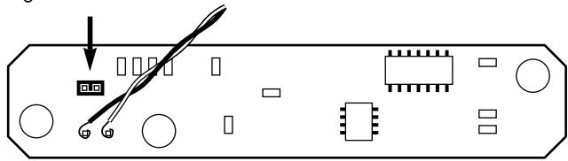
Figure 9
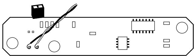
AWM650 Figure 9a

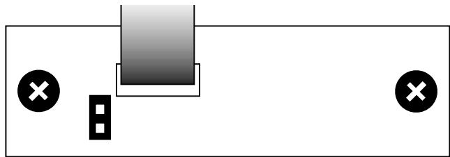
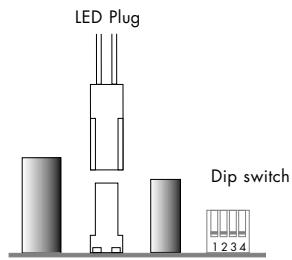
Disabling LED
(ACM65/80) see figure 9b
To disable the LED locate the plug shown in the diagram below.
- Hold speaker with drive unit facing upwards with RJ45 plugs to the right of the board.
- The plug is located to the left of the dip switches.
- Carefully unclip the plug.
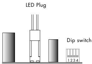
Figure 9b
ANCILLARIES
T-pieces
T-pieces comprise three RJ45 connectors wired in parallel. They are used to add the CASA Interface or Remote Output to systems and may have to be used when 'daisy chaining' loudspeakers, depending on the system topography. See the sub-sections Adding...Additional Speakers and Adding...CASA Interface for more details.
Local Input Module
The Local Input is a single pair of stereo RCA phono jacks on a panel that fits a single J-box. It connects to both speakers and the Keypad in its zone. Only volume and mute functions of the actual source connected to the Local Input can be controlled by the Keypad. Two RJ45 connectors are used to connect to the left and right speakers in the zone. The AWM70, AWM65, AWM650 and ACM80 have sockets that support this option. A 4/4 connector (Telephone Handset plug) is provided to connect to the zone Keypad at the end of the Keypad 'daisy chain'.
Remote Output Module
The Remote Output is a single pair of stereo RCA phono jacks panel that fits a single J-box and takes the place of a pair of speakers in a zone. The Remote Output converts the balanced high level CASA transmission to unbalanced line-level output. This option allows a zone to operate with an external power amplifier and passive loudspeakers in place of CASA Active Speakers. Additionally the Remote Output features an IR 3.5mm input jack that accepts IR commands from a third-party or CASA Remote unit and relays them back to the CASA Controller.
Sub-zone Volume Module (AWM65/70 only)
The Sub-zone Volume Modules are always supplied in pairs. These double-sided printed circuit boards fit the expansion slot on an AWM65/70 loudspeaker. Each Sub-zone Volume Module contains two volume controls which can be allocated to either Sub-zones A and B or to C and D using the switch settings on the PCB. Sub-zone A or C always relate to a speaker with a Sub-zone Volume Module installed. Sub-zone B or D will then be available from the '2nd speaker' socket of this speaker. In order to fit the Sub-zone Volume Module the finned heatsink must be detached from the front panel by removing the four allen-head bolts. The amplifier motherboard and Sub-zone Volume Module connector can then be accessed. The Sub-zone Volume Module PCB has a locating tab so it cannot be inserted in the wrong orientation. Before fitting, the links LK2 / 3 must be removed. These have been arranged so that the PCB simply cannot be pushed into its socket without their removal.
1 Figure 10a - Sub-Zone A 2
1 Figure 10b - Reserved 2
1 Figure 10c - Sub-Zone C
1 Figure 10d - Reserved 2
A dual DIP switch (Figure 10) is used to configure the Sub-zone Volume Modules in each speaker. The diagrams show the DIP switch when the Sub-zone Module is orientated with the pins up. The On position for the DIP switch is then to the right-hand side. The DIP switch setting must correspond to the Sub-zone in which the speaker will eventually reside. This may not be the same Sub-zone as the Small Keypad to which it connects.
Both left and right channel speakers in a Sub-zone need to be given the same switch setting.
Note: currently only A and C are valid settings for the Sub-zone Volume Modules since daisy-chaining of Sub-Zone Modules is not supported. Two other options are provided for future expansion.
When reassembling the speaker take care to reconnect the two pin connector to the IR receiver in the front baffle in the correct orientation. (In some Sub-Zone installations it is recommended that the IR receiver be disabled—see Figure 9 of the CASA Installation Manual.)
The AWM^TM650 and ACM^TM80 have the subzone module built into the amplifier PCB board. The subzone modules have the following settings enabling subzones to be activated/deactivated.
To set the subzone in the AWM650 and ACM80 the following dip switch settings are required.
Speaker used in zone that has not been split into subzones (normal use):
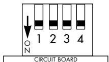
Local Input connected:
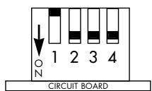
Subzone A:
Subzone B - same configuration as normal use since it is taking its volume control feed from the speaker in sub-zone

Subzone C:
Subzone D - same configuration as normal use since it is taking its volume control feed from the speaker in sub-zone
A:
CASA Interface
(Figure 11a/b)
The Casa Interface is a two-channel power supply and can be used to increase the power available in complex CASA systems enabling additional speakers to be used or maximum replay levels to be retained when using additional speakers. The output power of one interface will effectively support one pair of AWM70 loudspeakers. A local mains power supply for the interface will be required. See Figure 11a/b.
Two rear panel DIP switches control operation. The upper switch sets the unit to Normally On or Normally Standby and is used in conjunction with the 3.5mm trigger socket. The second DIP switch controls the Master/Slave function of the interface. The Slave mode is required for connection to a CASA Controller. The unit is shipped with both switches in the off (left) position set as Master/Normally On. See Figure 12a/b.

Figure 12a - Normally On
Figure 12a - Master

Figure 12b - Normally Off
Figure 12b - Slave
Figure 11a - Interface front panel

Figure 11b - Interface rear panel
CABLING
The CASA System is designed to use shielded Category 5 cable with RJ45 connectors (24 or 26 AWG with certain loading considerations - 120 foot runs for the AWM70 for instance). Longer runs can be considered with the CASA Interface power supply.
Twisted-pair cables comprise copper cores surrounded by an insulator twisted together to form a pair. The cable is a bundle of twisted pairs surrounded by an insulator. Unshielded twisted pair cable (UTP) is common in telephony applications but is unsuitable for use in CASA installations.
Shielded twisted pair cable (STP) offers better cross-talk and interference performance.
The EIA/TIA 568 Commercial Building Wiring Standard defines five categories of network cabling. CASA is designed for shielded Category 5 cable which is 100-ohm, four-wire twisted-pair cable (eight cores) certified to 100 Mbps (Mega bits per second) transmission rates in network installations. The cable has low capacitance and low cross-talk characteristics.
Of the eight cores available six (three pairs) are dedicated to providing a low impedance supply to the speakers. The remaining two cores carry the audio signal. The high frequency IR data is 'piggy backed' on the DC power supply lines. The screen of the shielded cable makes a required ninth connection.
All cables and terminations must conform to specifications to eliminate cross-talk and interference problems. Old style connectors and jacks are not suitable. Additionally, twists in the cable pairs must be maintained up to the connection point.
One other cable characteristic needs to be considered which relates to where the cable is installed. To comply with the National Electrical Code (NEC), all cable installed into the ceiling void (plenum space) must be in metal conduit or must meet local fire codes. Two types of insulation are used: PVC (polyvinyl chloride) insulation for normal use and fluoropolymer (Teflon) insulation for plenum-rated cable. We recommend the latter for CASA in-wall and ceiling installations.
There are no twists in the cable terminations which are wired straight through. The only criterion is that the pairs are adjacent, for example: Brown is alongside Brown/White; Blue is alongside Blue/White and Green is alongside Green/White, etc.
The 4/4 Serial Data connectors (Telephone Handset plugs) do not carry an audio signal and can use unscreened FCC-68 flat data cable (26 AWG). These cables are also wired straight through.
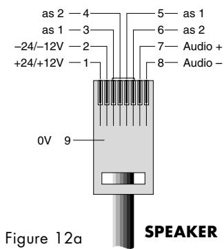
RJ45 Connector Pin Assignment
(Figure 12a/b)
Pin assignment for the RJ45 connector (Speaker):
| Pin | Signal | Comment |
| 1 | +24/+12V | 12V in Standby mode |
| 2 | -24/-12V | 12V in Standby mode |
| 3 | as 1 | |
| 4 | as 2 | |
| 5 | as 1 | |
| 6 | as 2 | |
| 7 | + Audio | |
| 8 | - Audio | |
| 9 | 0V Screen |
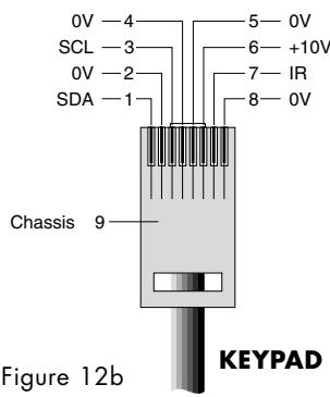
Pin assignment for the RJ45 connector (Keypad):
| Pin | Signal | Comment |
| 1 | SDA | Serial Data |
| 2 | OV | |
| 3 | SCL | Serial Clock |
| 4 | OV | |
| 5 | OV | |
| 6 | +10V | |
| 7 | IR | Infra red data |
| 8 | OV | |
| 9 | Chassis |
4/4 Connector Pin Assignment (Figure 13)
Pin assignment for the 4/4 Telephone Handset plug:
| Pin | Signal | Comment |
| 1 | 0V | |
| 2 | SDA | Serial Data |
| 3 | 0V | |
| 4 | SCL | Serial Clock |
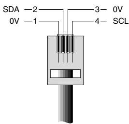
Figure 13
SYSTEM DESIGN
DESIGNING (Figure 14)
The CASA multi-source, multi-room system can be as simple as one Controller, one pair of Active Speakers and a Remote or Keypad/ Display. However, modular design and the ability to 'daisy chain' components mean a CASA System could easily comprise eight Controllers, feeding two sources to all 32 master zones and two further independent sources available for each set of four zones governed by each Controller (14 other sources in total) – this all feeding 64 Active Speakers and 96 Keypad/Displays. Local inputs could add 32 further inputs specific to each zone.
In planning complex CASA installations using more than one Controller, it is important to understand that sources can be made available globally to the whole system, to the four zones of one Controller only, or locally. Sources that are to be used globally must be 'looped through' each Controller. It follows that if the two main sources (Tuner and CD) are to be looped through to a second Controller six sources will be available, not the potential eight, if two Controllers were to be used independently. Sources to be added locally (an existing TV/Video system for example) need a Local Input module for connection to the CASA System.
The Remote Output module allows for the use of CASA connected sources and Keypad controls with existing power amplifiers and passive speakers.
Zones are divisible into a main zone and additional Sub-zones with independent control of volume and simple source switching within the Sub-zone. Sockets for these features are provided on some CASA speakers (AWM70, AWM65 AWM650 and ACM80).
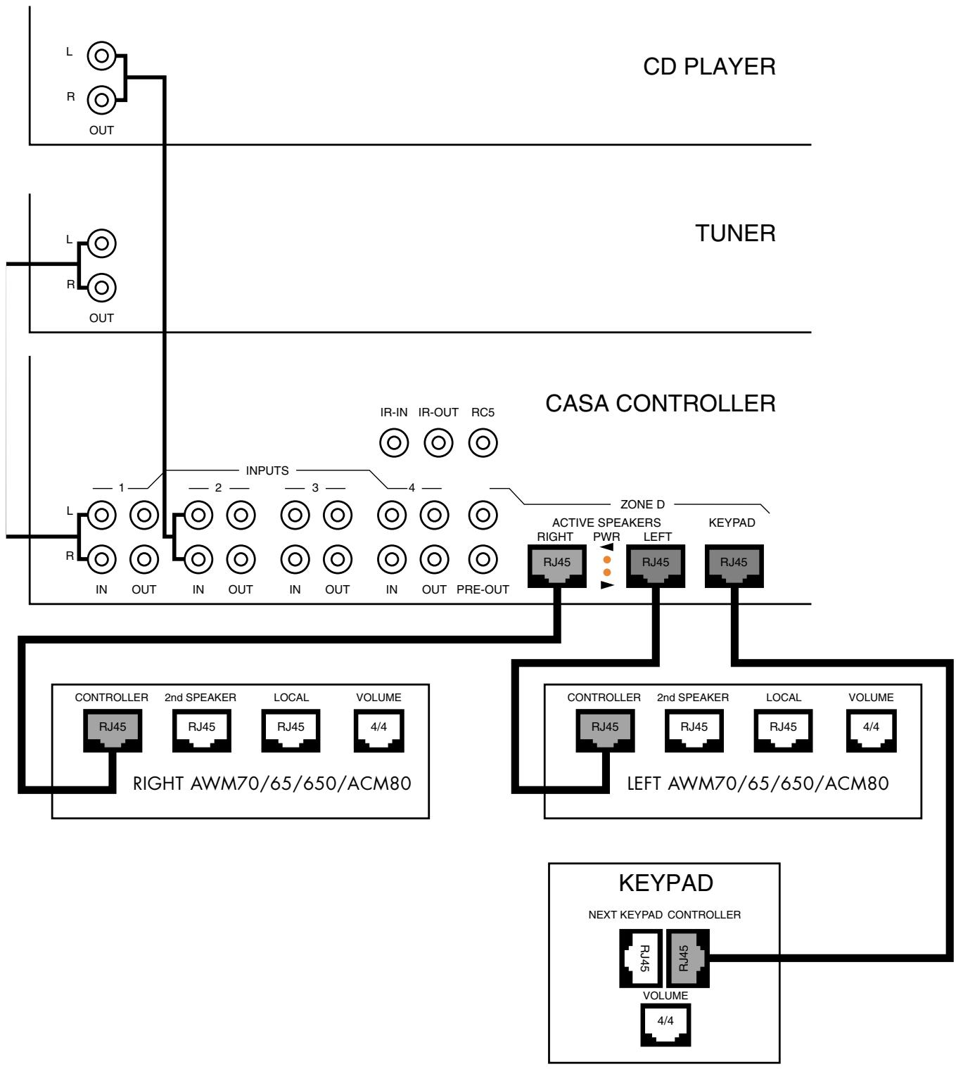

Key
In use

Figure 14
Not used
LOADING CONSIDERATIONS
System design is governed by the permitted number of speakers in any zone and, in a complete installation, by the loading constraints of the speakers on the Controller.
The loading units of individual speakers in the CASA System are as follows:
| Speaker Icon (each) | Loading units | |
| AWM70 | 70 | 100 |
| AWM650 | 650 | 50 |
| AWM65 | 65 | 50 |
| ACM65 | 65 | 25 |
| ACM80 | 80 | 30 |
| ACM60 | 60 | 25 |
The maximum total load on one Controller for full power capability is 400 loading units. Exceeding the total loading will not render an installation unsafe. The effect will be that all speakers cannot be played at maximum power output simultaneously. We do not consider this to be a major limitation though systems designed for full-house party use would be best designed within the limitation to achieve full power output. Maximum loading on any one output (ie. the left or right channel for each zone) of the Controller is 125 units. This loading must not be exceeded.
CASA Interface
The loading of speakers for one CASA Interface is as follows:
1 pair of AWM70 OR
2 pairs of AWM65 OR
2 pairs AWM650 OR
5 pairs of ACM60 OR
4 pairs ACM65 OR
4 pairs ACM80
Exceeding this loading will not make an installation unsafe but will limit the maximum volume at which loudspeakers can be played simultaneously.
Permitted permutations of speakers in a single zone are as follows:
| Master speakers | 'Daisy chained' | and | and |
| 70 | - | - | - |
| 70 | 80 | - | - |
| 70 | 65 | - | - |
| 650 | - | - | - |
| 650 | 650 | 80 | 80 |
| 650 | 650 | 650 | 60 |
| 650 | 650 | 80 | 80 |
| 650 | 650 | 65 | - |
| 650 | 650 | 80 | 80 |
| 650 | 650 | 65 | 65 |
| 650 | 650 | 80 | 80 |
Typical installation with maximum loading (400 units) all speakers simultaneous full volume
| Zone | Speakers | ‘Daisy chained’ | Sub-zone | Loading |
| A | 70 | - | - | 200 |
| B | 650 | - | - | 100 |
| C | 65 | - | - | 50 |
| D | 65 | - | - | 50 |
| Total | 400 |
Installation exceeding maximum loading (650 units) which will not allow all speakers to play to their maximum power outputs at the same time for instance in Party Mode — maximum volume will be down by about 4dB
| Zone | Speakers | 'Daisy chained' | Sub-zone | Loading |
| A | 70 | - | - | 200 |
| B | 650 | - | - | 100 |
| C | 650 | - | 650 | 200 |
| D | 65 | 65 | 65 | 150 |
| Total | 650 |
Installation exceeding maximum loading (800 units) which will certainly not allow all speakers to play to their maximum power outputs at the same time
| Zone | Speakers | 'Daisy chained' | Sub-zone | Equivalent Load |
| A | 70 | - | - | 200 |
| B | 650 | - | 650 | 200 |
| C | 650 | - | 650 | 200 |
| D | 65 | 65 | 65 | 200 |
| Total | 800 |
ADDING...
Additional Speakers
Additional speakers can be connected using RJ45 T-pieces.
The total loading on a Controller should not be exceeded if simultaneous maximum volume levels are required - see section Loading Considerations.
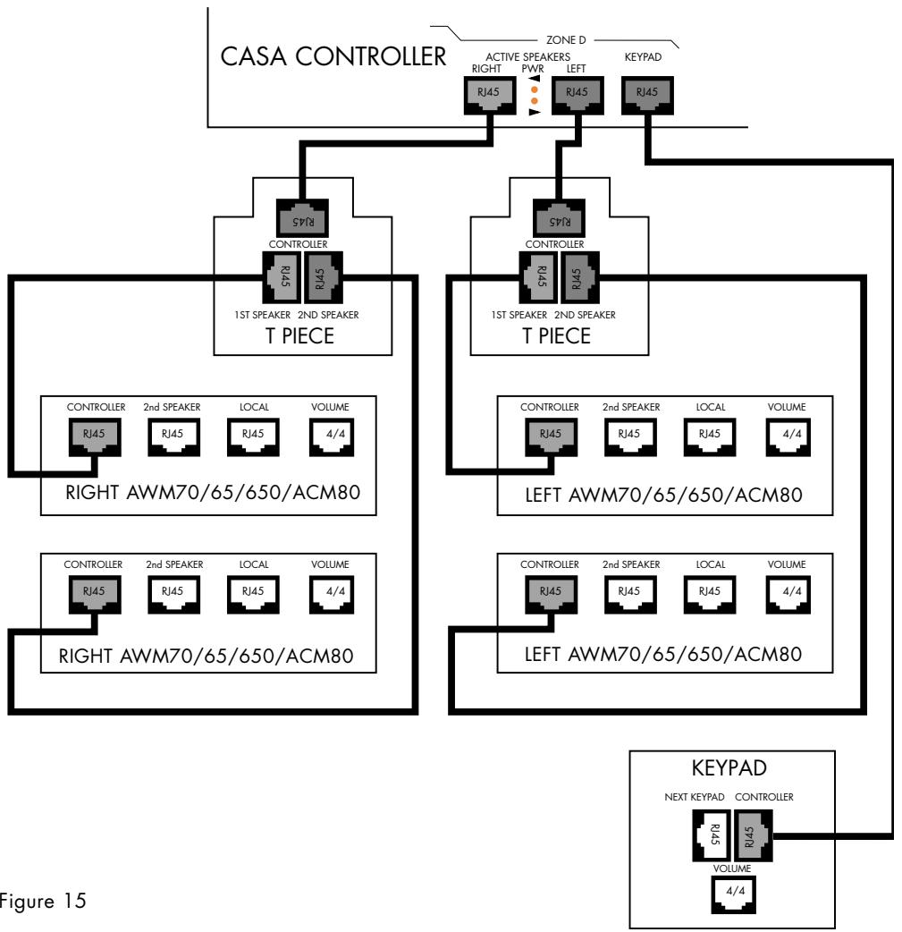
Figure 15
ADDING...
Additional Keypads
Additional Keypads can be used to provide additional control flexibility within larger or awkwardly shaped rooms. They can also be used as additional IR 'pickup points' in installations using predominantly ACM60/65/80 speakers that do not feature IR receiver/modulators. Up to three Keypads can be used in any zone. Additional Keypads are simply connected to the empty RJ45 connector marked Next Keypad on the last (or only) Keypad in the chain (as shown in Figure 16).
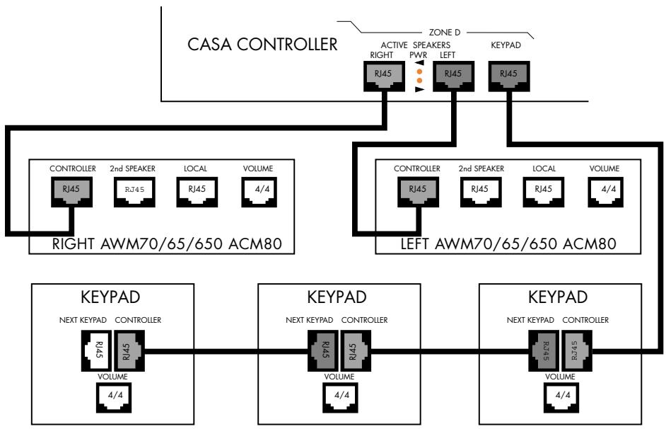
Figure 16
ADDING...
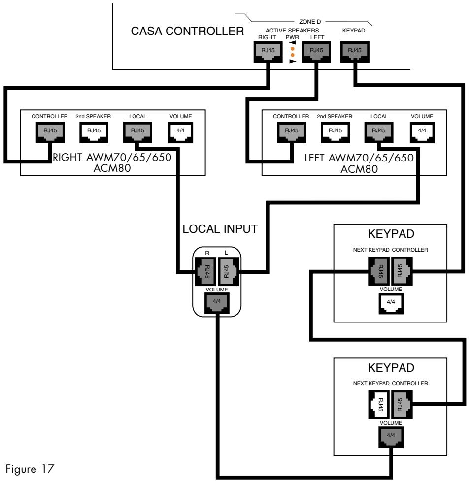
Local Sources
The Local Input module makes provision for a source to be connected locally within a zone rather than to the Controller and to be available to local speakers. This would allow, for example, an existing TV/video installation to be connected locally for replay through CASA speakers. Taking a feed from the TV fixed volume outlet would allow any connected source to be switched through the TV pre-amplifier for CASA replay, massively extending the number of connected sources.
RJ45 sockets marked 'R' and 'L' are connected to the sockets marked Local on the right and left speakers in the zone. The controlling Keypad connects to the Keypad socket of the same zone on the Controller.
An 4/4 connector (Telephone Handset plug) is provided to connect to the zone Keypad to provide local volume control. The 4/4 connector on the Local Input module and the 4/4 connector on the Keypad (both marked 'Volume') are to be connected (as shown in Figure 17).
If the variable volume of the local input needs to be fixed this can be done as part of the Initial Set-up procedure See the sub-section Initial System Set-up-System Sources for details.
ADDING...
Remote Output
This ancillary allows a zone to operate with a conventional external power amplifier and passive loud-speakers in place of CASA Active Speakers. It can be thought of as a local CASA System Pre-out socket. The Remote Output takes the place of a pair of speakers in a zone. RJ45 sockets marked 'R' and 'L' are connected back to the right and left sockets of one zone on the Controller. The controlling Keypad connects to the Keypad socket of the same zone on the Controller (as shown in Figure 18). Alternatively if the Remote Output is to be used in conjunction with other CASA speakers the feed from the Controller can be split using T-pieces (as shown in Figure 19). The feeds from the T-piece connected to the left socket on the Controller would go to both the left speaker and socket marked 'L' on the Remote Output; similarly for the right channel. In addition, the Remote Output features an IR 3.5mm input jack that accepts IR commands from a third-party and CASA Remote unit and relays them back to the CASA Controller.
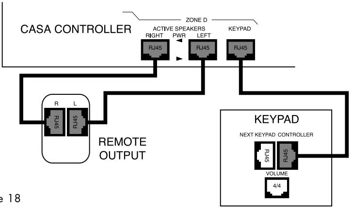
Figure 18
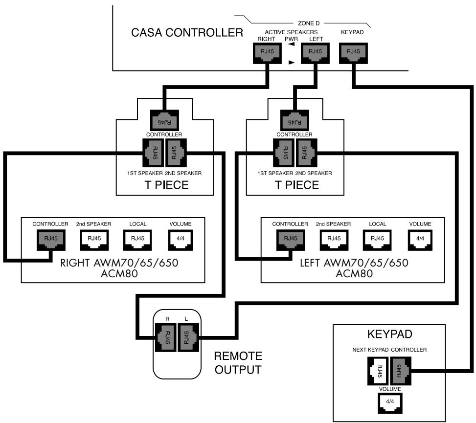
Figure 19
ADDING...
Additional Controllers (Figure 20)
Controllers can be 'daisy chained' up to a maximum of eight units. All Controllers are shipped set as Slave units. The first Controller in a system needs to be set up as a Master unit. Subsequent Controllers need only connecting through the CANbus jacks. See section System Sources in the chapter Initial System Set-up for details.
Note that 'looped through' sources available to every connected Controller restrict the total number of sources available.
If two or more Controllers are used in the same system we suggest you connect them so that only one Flood IR emitter works. This will avoid potential interference that may cause erratic or intermittent operation see sub-section Using With...Any IR controlled source component for further considerations. Some systems may benefit from the increased signal strength provided by multiple Flood IRs. As there are no hard and fast rules, experimentation will be needed.
Adding a 2nd Controller with CD and Tuner inputs 'looped through' available to all Zones 1A-1D and 2A-2D but with Laserdisc and Cassette sources only available to Zones 2A-2D
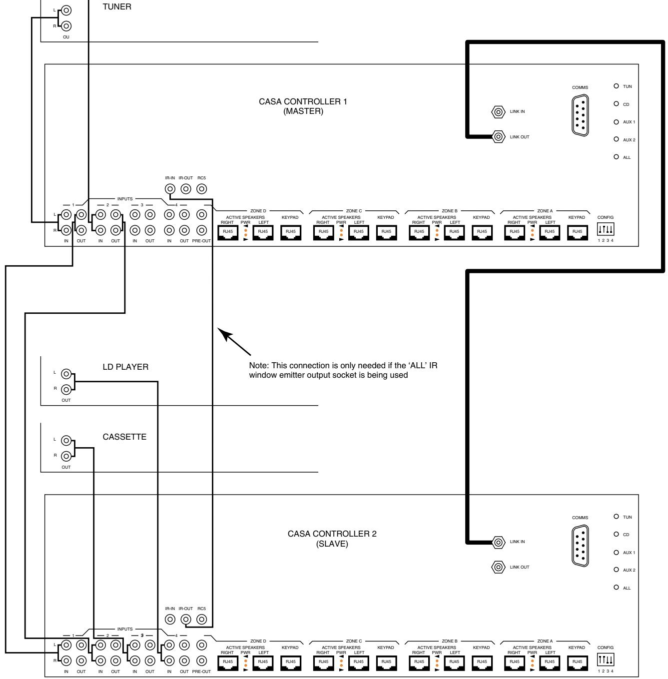
Figure 20
ADDING...
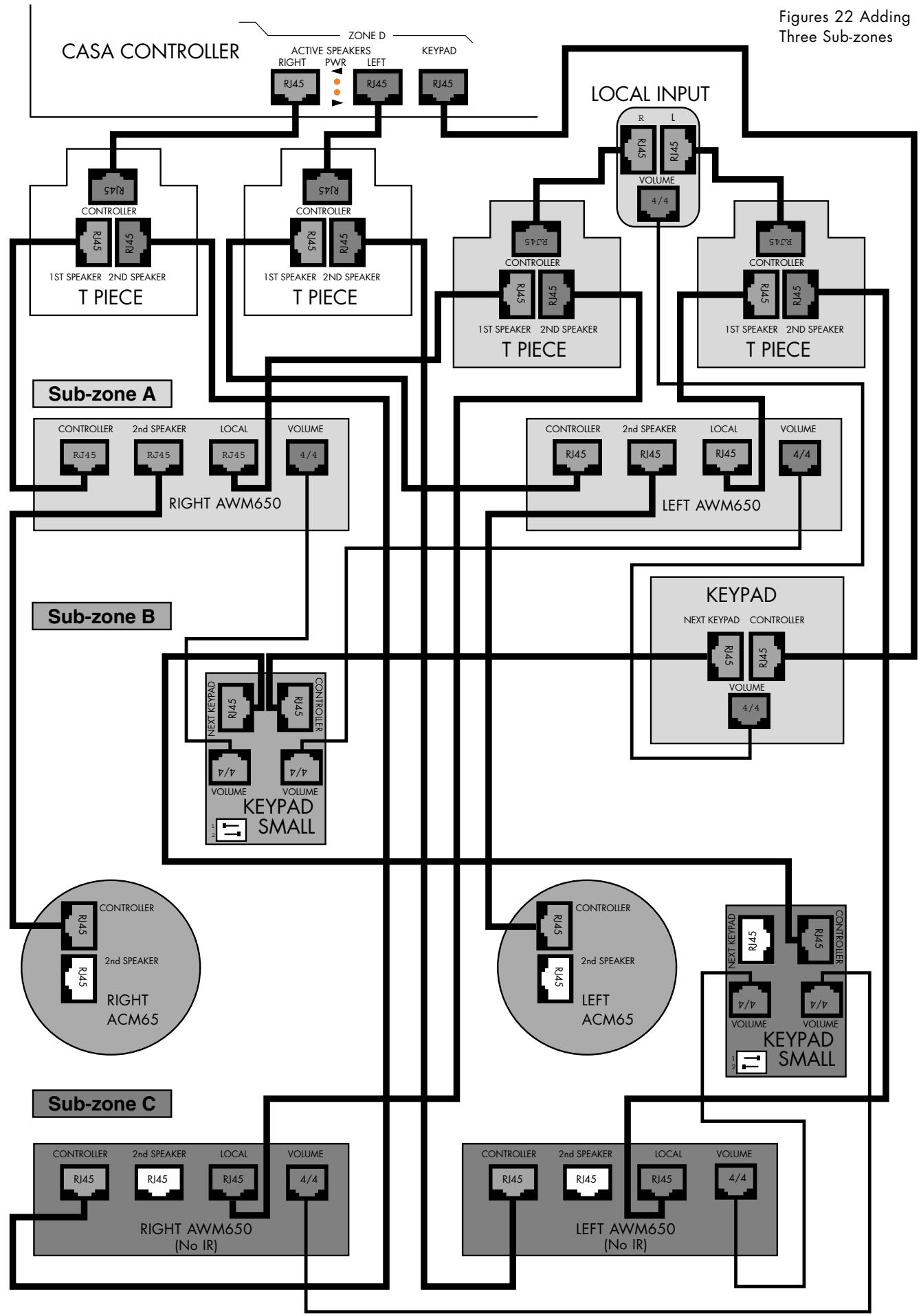
Sub-zones (Figures 21 and 22)
Figure 21 shows the simplest of Sub-zones. Figure 22 shows one of the more complex configurations with a local input available to three Sub-zones (A, B and C). Both pairs of AWM loudspeakers need to be fitted, or have the Sub-zone module activated, with Sub-zone Volume Modules switched to the correct addresses. Sub-zone C must have the IR receiver disabled since confusion will result if a remote handset is used with these speakers. Sub-zone D could be created by connecting a pair of ACM65s to the AWM650/70s in Sub-zone C. The daisy-chain order of all Keypads is unimportant, remember that when using Sub-zone C the audio output from the controller is split to A and C by a T-piece in each channel.
IR remote control can only be implemented in Sub-zone A. The Small Keypad has no IR sensors and speakers with IR receivers operating in Sub-zones other than Sub-zone A need to have their IR receiver disabled by removal of the IR links — see Figure 9 Page 33 of the CASA Installation Manual.
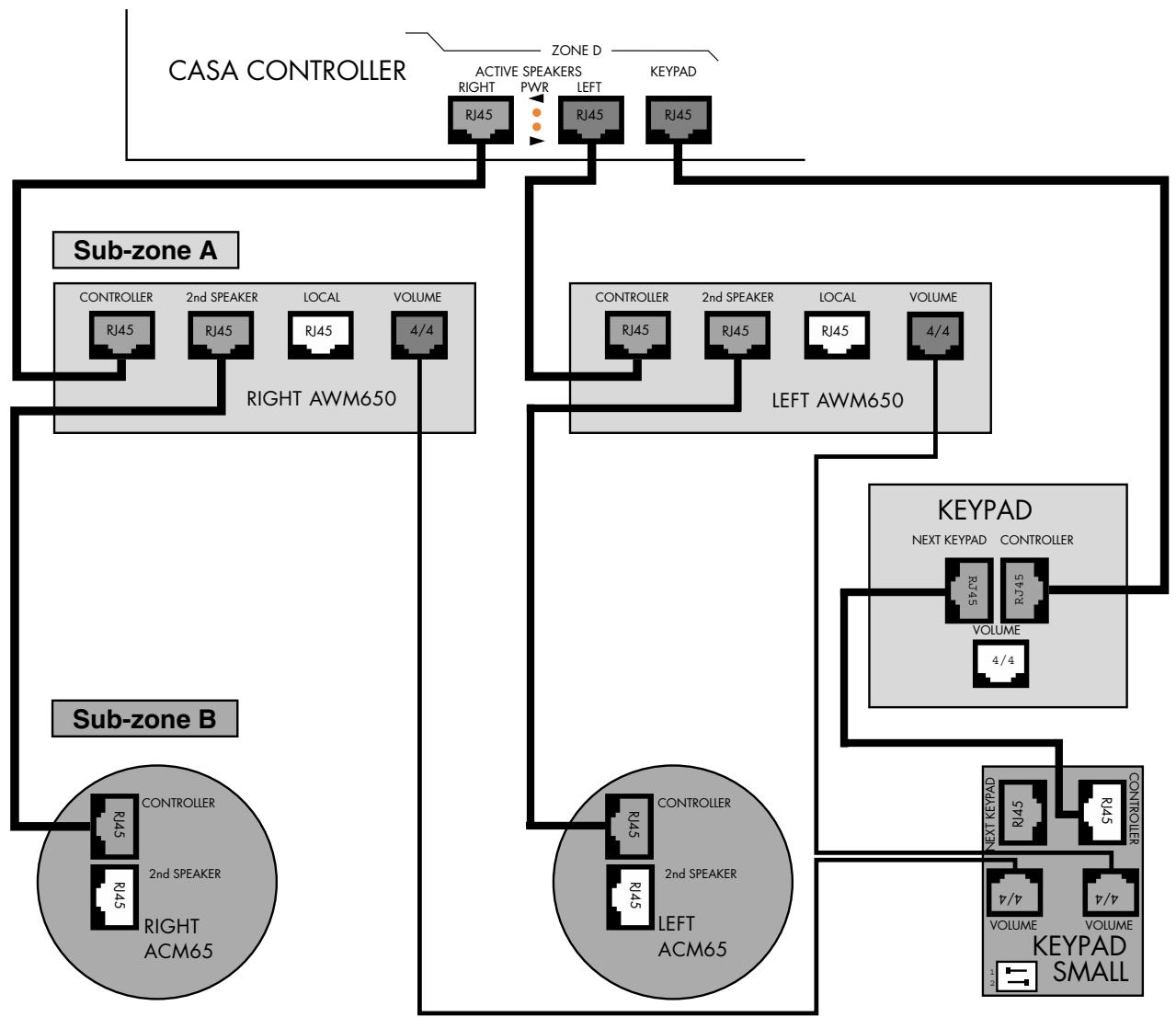
Figure 21 Simplest possible Sub-zone
ADDING...
The CASA Interface
The CASA Interface power supply is added using two T-pieces (as shown in Figure 23). The left socket on one zone of the Controller is connected to the T-piece which
Speaker socket. The speakers are then connected to the 1st Speaker socket on the T-piece. Channel orientation is not important as the Interface is not being fed via its own Audio In sockets, however for clarity L-L and R-R connections are shown. A local mains power supply will be needed for the Interface.
Figure 23 Adding The CASA Interface
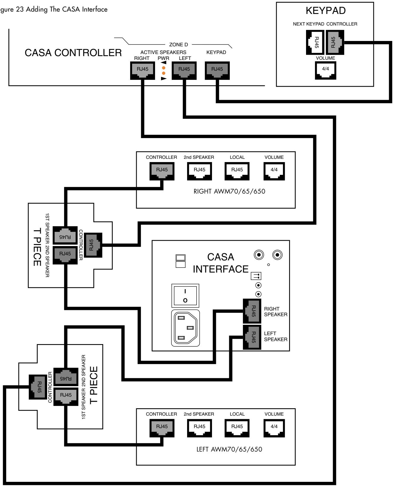
is in turn connected to the CASA Interface by the 2nd
ADDING...
Two identical source components
Two identical source components can be successfully used with the CASA System under remote control. When using two identical sources the front panel Flood IR must be de-activated.
Identical tuners may be used to extend the number of available presets for example. The IR outputs Tun and Aux 1 carry one channel of IR information while CD and Aux 2 carry another. As long as the two identical components are used one each on these separate channels they can be independently controlled.
ADDING...
Two RC5 code controlled source components
If two pieces of RC5 equipment of different types are to be used it is recommended that one is connected to the dedicated RCA phono output carrying RC5 codes and that the other be controlled either using a 'stick-on' IR window emitter or 'looped through' via the RCA sockets carrying RC5 codes from the first piece of equipment.
If two identical pieces of RC5 equipment are to be used 'stick-on' IR window emitter must be used for both pieces of equipment.
ADDING...
Source with lower than average output
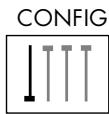
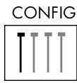
Figure 24a/b/c/d)
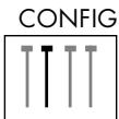
To accommodate source components with lower than average output the sensitivity of the two Auxiliary inputs (Aux 1 and Aux 2) can be independently increased by 9dB relative to the Tuner and CD inputs. Set switches 3 and 4 on the DIP switch marked 'Config' on the rear panel on the Controller in the down position.
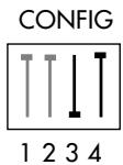
Figure 24a
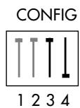
Figure 24b
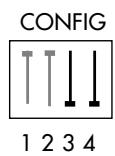
Figure 24c
Figure 24d
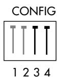
Figure 24c/d
Figure 24a/b
Aux 1 +9dB Aux 2 +0dB (left)
Aux 1 +0dB Aux 2 +9dB (right)
Aux 1 and Aux 2 + 9dB (left)
Aux 1 and Aux 2 +0dB (right)
Home automation
The RS-232 socket offers open architecture control of and feedback from the CASA System components.
INITIAL SYSTEM SET-UP
REMOTE
If they have not already been fitted or to fit replacement batteries: remove the two screws from the base of the remote control and remove the bottom cover. A conventional 2 × AAA battery carrier is tucked inside. Slide out the battery carrier with its two wires attached. Insert the appropriate batteries noting correct polarity. Carefully insert the battery carrier into the bottom of the handset and push gently inside, taking care not to trap or damage any wires. Fit and secure the bottom cover.
Check the remote operation by looking for the red LED tell-tale lighting on the master speaker when a keypress is made on the remote (AWM70, AWM65 and AWM650).
GENERAL REMARKS
The installer set-up modes require a combination of long keypress sequences and should not be accidentally chosen by the user. With the system in set-up mode any 'illegal' keypress will be ignored and will elicit no display response. Any set-up functions left with no key presses for 1 minute will revert without saving any settings that had been changed.
The standard time for the display reverting (to displaying the time for example) is 3 seconds
Sources can be set-up individually and do not all have to be set-up and stored at one time. Changes can be made to individual source settings, if for example a CD player is upgraded or a component moved to another input, without affecting the rest. You do not have to set-up all sources each time set-up mode is initiated. All source and clock settings are protected by battery back-up.
In all set-up modes (both consumer and installer) ZONE OFF and ALL OFF key presses will elicit the display Cancel and the system will be taken out of set-up mode.
CLOCK SET-UP
The zone has to be off. Press the 35 key for 6 seconds to put system into clock set-up mode. The display will show Set clk and will then flash the time 11:32 (example) indicating it can be changed. The and keys are used to set the hours; the and keys are used to set the minutes.
Press the key again (short press) to show the 'hide clock' status. Each zone can display either the clock on each Keypad (show clock) or a simple double dot indicator ( ) (hide clock). The < and > keys will toggle between Hide clk and show clock. Choose which is required and press the key again (short press) to save the time and 'hide clock' status. The Keypad/Display will show that the system is saving the settings (Savine) and the display will then revert.
SYSTEM SOURCES
With the system all off, three long presses (3 seconds) on the, <, MUTE and > keys in sequence (on either the Keypad/Display or Remote control) will take the CASA System into set-up mode. The display will show Set-up. The << and >> keys are then used to toggle between Master? and Slave?. All Controllers are shipped set as Slave units.
Pressing either the TUNER or CD keys on either the Keypad or Remote will change the display to either Tn type?or CD type?. The and keys can then be used to select the appropriate manufacturer and type from the list. Manufacturer's names are restricted to five letters only; CD players also show if the machine is a single or multi-disc player (CD=Pions3 Pioneer single disc CD player, for example). Products using RC5 compatible codes can also be selected in this way.
If the Controller has been defined as a Slave, Aux 1 and Aux 2 are already set up with the Master Controller sources. Keypresses on either TUNER or CD source keys will elicit the response master on the display and these cannot be changed.
To set up a source for either Aux 1 or Aux 2 keys, press the key in either Aux 1 or Aux 2 position (Keypads will be shipped without keys fitted in these positions but an appropriate key for the new source component should be selected and fitted from those provided - see Keypad Installation sheet) to change the display to either A1 or A2. The 串 and 串 keys can then be used to select the appropriate source from the list of source types (A1=CD Aux 1 set for CD player for example). The 串 and 串 keys can then be used to select the appropriate manufacturer and type from the list as above. In the case where Aux 1 or 2 are set to source type Server (A1 = Server) the volume buttons + and - can be used to select alternative outputs where these are available. The available source names for use and during set-up are as follows:
For use
During set-up
| CD | CD |
| Tuner | Tn |
| CD2 | CD2 |
| Tunr2 | Tunr2 |
| LD | LD |
| Cass | Cass |
| DSS | DSS |
| VCR | VCR |
| DVD | DVD |
| - | A1 |
| - | A2 |
| None | None |
One long press (3 seconds) on the MUTE key (on either the Keypad/Display or Remote control) will save the new source settings (display will show Saving) and take the system out of set-up mode.
If there is a local input present press LOCAL and the display will show Lvol. This indicates a variable volume for the local input. If this needs to be fixed - if the volume control of a local device needs to be used, for instance - press the vol- key. (A typical example of where a fixed input may be useful is when taking the L and R channels from an AV processor and doubling up Casa speakers as left and right with the volume controlled as normal from the processor when the Local input is selected.) The display will show Lvol=00 and will decrement in volume units of 5 down to the desired fixed level. A long press on MUTE will save all settings in the normal way.
Review
To review source settings with the system All off, three long presses (3 seconds) on the <<, MUTE and >> keys in sequence (on either the Keypad/Display or Remote control) will automatically cycle through the settings for each source. See section Reviewing System Sources in the chapter System Operation.
Dip switches
Please note: If the dip switches are altered with the system live, the change will only be recognised if the configured component is powered down and up again. This can be done by disconnecting it and then reconnecting, or power cycling the controller.
TONE CONTROL AND BALANCE
Tone control and balance are set on a zone by zone basis. When the zone is off one long press (3 seconds) first on the + and then the - key (on either the Keypad/Display or Remote control) will take the CASA System into tone control set-up mode. As this will also take the system into CD1 play mode any CD listening material you wish to use for tone control setting should be loaded beforehand in CD Player 1. The degree of Treble and Bass cut or boost can be judged from the CD source playing as the CASA tone controls operate in real-time.
The CASA tone controls are not designed to replicate the Treble and Bass controls provided on the average preamplifier. They have been specifically tailored to provide installers with a solution to many room acoustic problems. Architectural constraints may dictate that speakers will be too close to corners or conversely without the necessary bass reinforcement from room boundaries. The bass cut and boost centred below 100Hz can help here. For speakers in acoustically highly reflective or overdamped rooms the shelving treble cut and boost will assist. (See Figure 26 for details of roll-over frequencies and the precise degree of cut/boost available.)
The display will initially show the current volume. The and keys can be used to cut or boost bass. The initial keypress will show the current bass setting (Bass - if no changes have been stored or Bass-1 (example)) further single keypresses will take the system from Bass-7 to Bass+7.
The < and >1 keys can be used to cut or boost treble (see Figure 26 for details of roll-over frequency and degree of cut/boost). The initial keypress will show the current treble setting (Treble - if no changes have been stored or Treble-1 (example)) further single key presses will take the system from Treble-7 to Treble+7.
The FAV.STN and RANDOM keys can be used to adjust the balance. The initial keypress will show the current balance setting (-B 1 - if no changes have been stored or +1B 1 - 1 (example)) further single key-presses will take the system from +7B 1 + 7 (balance hard over to left) to +7B 1 + 7 (balance hard over to right). A single keypress changes both numbers.
A long press on the MUTE key on either the Keypad or Remote control will save the Tone and Balance settings for the zone. The Keypad/Display will show Saving.
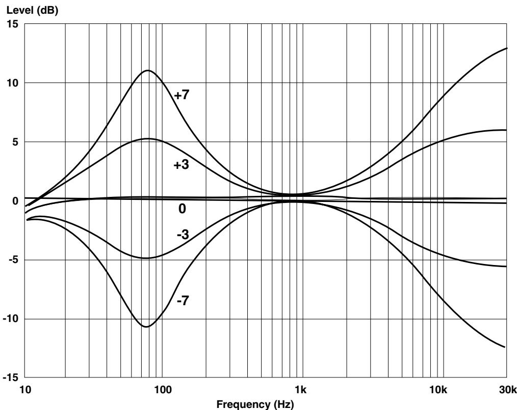
Figure 25
ZONE SETUP
With the system off long presses (3 seconds) on the , MUTE and the key in sequence (on either the Keypad/Display or Remote control) will take the CASA System into Zone Setup mode. The display will automatically show Zone Set before showing the default setting NoSubs?. The and keys can then be used to toggle between NoSubs? and UseSubs?. Pressing the key again permits the Zone to be included or excluded from Party Mode. The display shows Parte? as default. The and keys can then be used to toggle between Parte? and NoParte?. Pressing the key again permits the Zone to be configured for use with an Output module. The display shows NoOutPM? as default. The and keys can then be used to toggle between NoOutPM? and OutPM?.
Pressing the key again permits a selection of turn on volume options for that zone. The display shows LastVol? as default. The and keys can then be used to scroll through LastVol?, Ypreset? and Fixed?. For these last two options the volumecontrol can then be used to set either a preset turn on or fixed volume for that zone.
Pressing the >> key again permits the Zone to be set to have a maximum volume. The display shows MaxV=80? as default. The and keys can then be used to toggle between MaxV=80? and MaxV=7?. The volume control can then be used to set maximum volume for that zone.
If a Fixed volume level has been set before this maximum volume option effectively 'disappears' from the menu.
One long press (3 seconds) on the MUTE key (on either the Keypad/Display or Remote control) will save the new Zone settings (display will show Saving) and take the Zone out of set-up mode.
SYSTEM OPERATION
REVIEWING SYSTEM SOURCES
With the system All off, three long presses (3 seconds) on the , MUTE and keys in sequence (on either the Keypad/Display or Remote control) will take the CASA System into review mode. The display will automatically show Review and the current firmware version V 1.00 (for example) before showing the source set-up details for Tuner, CD, Aux 1 and Aux 2 in order (CD=PionS [pause] Tn=Denon [pause] A1=CD [pause] A1=RC5 [pause] A2=Cass [pause] A2=Song (for example)). The display will then revert.
TIMER
With the zone on or off, a single press on the case key will automatically cycle through the current settings (Time on [pause] 911:32 (Time On example) or n11:32 (if timer has not been set) [pause] CD (selected timer source for example) [pause] Time off [pause] 912:01 (Time Off example) or n12:01 (if timer has not been set)).
A long press on the case key for 3 seconds with the zone off puts the system into timer set-up mode. The display will cycle through the current settings until it reaches the timer setting when it will flash to show that a change can be made (Set timer [pause] Time on [pause] y11:32 (Time On example) [ case key press] CD (selected timer source for example) [ case key press] Time off [pause] y12:01 (Time Off example) or n12:01 (if timer has not been set) case key press to save Saving).
The Vol key is used to toggle between on/off (91132 n1132) for each timer event. The < and keys can then be used to set the hours and the < and keys used to set the minutes for each event. The source for timer operation can be selected using the appropriate source key. The chosen source then shows in the display. The final case key press will save the new timer settings, the display will show saving and then revert.
The tilde symbol will appear on the far left of the display when the zone is switched off to indicate that the timer is set for that zone. All sources other than a locally connected source can be turned on by the Timer function.
SLEEP
With the zone on, a long press on the keys key for 3 seconds puts the system into sleep set-up mode and the display will show Sleep? The and keys can then be used to select Disabled, 20 mins, 40 mins, or 60 mins settings. A short keys key press will save the new sleep settings (display will show Saving if the status has been changed) and the display will then simply read Sleep until the zone automatically turns off.
The system will remain switched on and sources can be changed until the Sleep time has expired. At that time the volume will automatically turn down and the zone switch off. The Keypad/Display will operate as normal but will revert to the Sleep display while Sleep time has yet to run.
If sleep set-up mode is accessed a second time while the system is in sleep mode the display will show the remaining minutes before sleep as its first choice in the Disabled, 20 mins, 40 mins, 60 mins display. Sleep delay can be reset or disabled at any time. The Sleep function can turn off all sources, including the Local source output through the system.
KEYPAD CONTROLS
General Remarks
As a general rule key presses that do not perform any function at the time they are pressed will elicit the display message Can't do. This display will revert after 1 second.
In set-up mode, functions left with no key press for one minute will revert to the previous mode without saving any changed information.
If commands are actioned on two Keypads simultaneously in zones with more than one Keypad, the Keypad in the circuit nearest the Controller has priority.
Switching on
Any source key (including the LOCAL key), the FAV.STN or RANDOM can be used to switch the CASA System on. The system will go from standby to playing or selecting the appropriate source and will turn up the volume to the last set volume level unless the volume on has been pre-set. The display will revert to showing the chosen source.
OFF key
A short press on the OFF key will turn the volume down and switch the zone off. The display will show the Source and volume level ramping down ( Tuner [example]) before showing Zone off and then reverting to the normal standby display, showing or hiding the clock as set by the user ( 1132 or #).
A long 3-sec press on the OFF key will turn the volume down and switch the system to standby. The CASA System automatically sends the appropriate Stop and Standby commands to connected source equipment when this keystress is made. The display will show the Source and volume level ramping down ( Tuner 串串 [example]) before showing A11 off and then reverting to the normal standby display, showing or hiding the clock as set by the user (11#32 or #).
In a normal Zone a short press on the OFF key will switch the Zone off. A long press (3 sec) will switch off all zones with the message All Off appearing on all Displays. In contrast when Sub-zones have been set-up three degrees of 'off' can be achieved. The Display/Keypad in Sub-zone A will additionally respond to a medium keystress on the OFF key which switches off all the speakers playing within the Zone. The Keypad/Display will show Zone Off. The ON/OFF key on the Small Keypad does not have this intermediate function.
A further consideration is whether just Sub-zone A is playing or whether other Sub-zones are playing. The operation of the OFF key in the Keypad/Display is best shown in the following matrix.
| Sub-zone speakers other than A playing | Just Sub-zone A playing | |
| short keypress | Only Sub-zone speakers off Off | Zone switched off Zone off |
| mid keypress (1.5 sec) | Zone switched off Zone off | NO FUNCTION |
| long keypress (3 sec) | System off All off | System off All off |
VOL key (Volume)
The vol key is a rocker marked ^+ at the top and - at the bottom that gently increases or decreases the volume from its previous level. The display will show the level counting up or down (Vol 26 (example)) as the vol key is used. The display will then revert to show the currently selected source.
MUTE key
The MUTE key toggles between the normal listening volume and the muted volume (40 dB below listening level). The display will show the Source and volume level ramping down (Tuner # (example)) before showing Muted. All functions work normally even if the system is muted except the VOL + key which takes the system out of mute before turning up the volume.
The keypress reduces the volume and will display the normal volume display before reverting to the muted display. Both the muted, listened to, volume and the normal unmuted level will be reduced.
A second press on the MUTE key will restore the normal listening volume. The display will show the Source and volume level ramping up to the previously set numerical level (Tuner 27 (example)). The display then reverts to the currently selected source name CD or Tuner P1 (example).
key (Favourite Station)
The FAV.STN (Favourite Station) key selects Preset 1 on the selected tuner or Channel 1 if the selected source is a satellite receiver. The display will show Fav stn and then revert to Tuner P1 if the source was the tuner or DSS if the source was satellite. Installers should ensure that the tuner Favourite Station is tuned to Preset 1.
RANDOM key
The RANDOM key toggles the selected CD source in and out of Random Play mode (Shuffle) if that source was already selected. If the RANDOM key is pressed when a source other than CD is selected the system will search out the 'most random' mode available on the player, i.e. a random track from a random disc on a multi-CD player will take priority over random track choice from a single disc.
and keys
The 1< and >1 keys perform slightly different functions depending on the source selected when they are pressed. For
tuner or satellite sources the 1< key will select one preset or channel down from the current choice, the >1 key will select one preset or channel up. The display will show Preset or Preset*if Tuner is selected) and Channel or Channel* (if a satellite source is selected) reverting to display the new channel or preset number selected ( Tuner P3 or DSS Ch01 (examples)).
If a Laserdisc, DVD player or video recorder is the selected source, the and keys perform search with picture backwards and search forwards respectively (the display will change to # Search or Search). The search function will only operate while the key is being held down. When the key is released play is resumed and the display will revert to the appropriate source name (LD, DVD or VCR (examples)).
Note: because of the repeating nature of the IR code for the search function other IR functions in the Controller will be blocked. If a keypress is made while the selected source is searching the display will show Buses and the request will not be actioned.
If a cassette deck is the selected source and if the function is supported by the machine, the 1 and 2 keys will operate as previous and next track keys (the display will change to 4 Track or Track). Note that the display will revert to showing the source 5 without waiting for the machine to find a track.
If a sound server is the selected source the < and >1 keys will operate as the Next track and Previous track function.
and keys
As with the < and >1 keys, the < and >1 keys perform slightly different functions depending on the source selected when they are pressed. For CD and Tuner sources there is no appropriate function and the display will simply show Can't do.
If a multi-disc CD player is the selected source the and keys function as previous Disc ( disc) and next Disc (disc) keys. A long press on the key will change the display to a flashing CD 1, the number will increment at increasing speed up to the maximum number of CDs in the multi-disc player. When the correct number is reached CD 23 (example) the button should be released. Only after 3 seconds free from up and down key-presses will the code be sent to select that disc. During that period the CD number can be adjusted using the and keys. The display will then revert.
If a satellite receiver is the selected source the < and keys will skip down or up 10 channels. The display will show #10Chann or Chann#10 and revert to showing the newly selected channel DSS Ch21 (example).
If a video recorder or cassette deck is the selected source then the and keys function as rewind (VCR reu and Cass rew) and fast forward (VCR ffud and Cess ffud) keys. This function can be stopped by the STOP key on the remote handset (Stop appears on the display which then reverts to showing the selected source). Pressing the VCR or CASS source key on the Keypad/Display takes the selected source out of fast forward/rewind and into play mode, the display reflects this showing either VCR play or Cass play before reverting to the source name.
If a Laserdisc or DVD player is the selected source the « and » keys operate as previous and next Chapter keys. The display will show Chapter or Chapter before reverting to show the source LD or DVD.
If a Server is the selected source the and keys performs a Previous and Next album function.
LOCAL key
Pressing the Local key switches the zone to operate on the Local source. The volume is turned down (the display shows the initial source and the volume decrementing Tuner). The display shows the Local source is selected and turns up the volume to the previously set level (Local ). The display then reverts to show the source Local .
Source keys
In addition to their On functions the Source keys all switch to and actuate the appropriate component. The display reflects this by showing Cass Play or CD Play before reverting to simple source names Cass and CD.
If the system is in Local mode the system will turn the volume down (the display shows the Local source and the volume decrementing Local). The display then shows the selected source Cas play and turns up the volume to the previously set level (Cass). The display then reverts to show the selected source Cass.
Note: When the system receives a CD play command from a CD keypress it disregards subsequent CD play key presses from anywhere in the system for 5 seconds. This is to allow the chosen CD source to go into play without interruption or confusing subsequent key presses that may be interpreted as Replay commands by some CD players.
See the chapter Party mode for special information on operation of the source keys in party mode.
key
The base key can be used to review or set the timer and sleep functions. On a short keypress the display will automatically cycle through the current settings. If the Time Off function of the timer has not been set and the Time On function has been set, the display will show Time on [pause] 11:32 [pause] CD (selected timer source for example) [pause] Time off [pause] n12:01 . The display will then revert.
If the Time On function of the timer has not been set and the Time Off function has been set, the display will show Time on [pause] n11:32 [pause] CD (selected timer source for example) [pause] Time off [pause] y12:01 . The display will then revert.
For long press responses see Timer and Sleep sections of the System Set-up chapter.
REMOTE CONTROL
STOP key
The Remote control duplicates all functions of the Keypad keys with the exception of the case key. There is, however, an additional STOP key provided. This puts any selected source into stop from any other mode (should this function be appropriate to the source selected).
ALL OFF key
This duplicates the effect of a long 2-second press on the Keypad OFF key - the volume is turned down and the system is switched to standby. The appropriate Stop command is sent by the CASA Controller to connected source equipment and the switched mains outlet turns off after 1 minute.
The Keypad in the zone (if fitted) will show the Source and volume level ramping down (Tuner # (example)) before showing all off and then reverting to the normal standby display, showing or hiding the clock as set by the user (1132 or #).
ZONE OFF key
This duplicates the effect of a short press on the Keypad OFF key - the volume is turned down and the zone is switched off. The Keypad in the zone (if fitted) will show the Source and volume level ramping down (Tuner # (example)) before showing Zone off and then reverting to the normal standby display, showing or hiding the clock as set by the user (11:03 or #).
SMALL KEYPAD
Switching on
Any source key can be used to switch the CASA System on. The system will go from standby to playing or selecting the appropriate source.
ON/OFF key
If the Small Keypad resides in a Sub-zone other than Sub-zone A a long press on the ON/OFF key will turn the volume down and switch the whole zone off. Note: this means that the All Off capability of the Keypad/Display is not available from the Small Keypad other than in Sub-zone A.
A short press on the ON/OFF key will switch off the Sub-zone.
If the Small Keypad resides in Sub-zones B to D and Sub-zone A is not playing pressing the ON/OFF key will switch on the last selected source in that Zone.
When Sub-zone A is already playing the ON/OFF key supports a 'follow' facility bringing up the volume in the resident Sub-zone with the Sub-zone A source. This is the only way to hear the local source connected in Sub-zone A from a Sub-zone controlled by a Small keypad.
VOLUME+ and VOLUME- keys
The VOLUME+ and VOLUME- keys gently increase or decrease the volume from its previous level.
< and > keys
The < and > keys perform slightly different functions depending on the source selected when they are pressed. For tuner or satellite sources the < key will select one preset or channel down from the current choice, the > key will select one preset or channel up. If a Laserdisc, DVD player or video recorder is the selected source, the < and > keys perform search with picture backwards and search forwards respectively. The search function will only operate while the key is being held down. When the key is released play is resumed. If a cassette deck is the selected source and if the function is supported by the machine, the < and > keys will operate as previous and next track keys.
If a sound server is the selected source the < and > keys will operate as the Next track and Previous track function.
>>key
As with the < and > keys, the key performs slightly different functions depending on the source selected when it is pressed. For CD and Tuner sources there is no appropriate function. If a multi-disc CD player is the selected source the key functions as a next Disc key. If a satellite receiver is the selected source the key will skip up 10 channels per keystress. If a video recorder or cassette deck is the selected source then the key function as a fast forward key. If a Laserdisc or DVD player is the selected source the key operates as a next Chapter key.
If a Server is selected source the >> key performs a Next album function from the Server.
Source keys
In addition to their On functions the Source keys all switch to and actuate the appropriate component. Note: When the system receives a CD play command it disregards subsequent CD play keypresses from any-where in the system for 5 seconds to allow the chosen CD source to go into play without interruption or con-fusing subsequent keypresses that may be interpreted as Replay commands by some CD players.
USING WITH...
Any source components
Before selecting source equipment you should study the source equipment addendum and choose equipment that is both supported by the CASA code set and which is functionally best suited to the system(s) in which it will be used.
It is recommended that the source equipment should be plugged into the switched mains outlet. If the source equipment is being used for other duties and consequently not plugged into the CASA Controller's switched mains outlet the CASA System will not be able to turn it on or off.
Note: due to potential functional reliability problems the CASA System does not send Standby commands to put the source equipment from On into Standby.
Any IR controlled source components
As a general rule 'stick-on' IR window emitters should be used in preference to the Flood IR for maximum operational reliability.
Tuners
Tuners that do not support both Favourite Station and direct preset access functions will not display a preset number as part of the source display ( Tuner and not Tuner P2 for example).
Only the first nine presets will be shown in the CASA display (Tuner P1 through Tuner P9). Customers' preferred stations should therefore be tuned to the first nine presets on the tuner.
The and keys perform no function.
CD players
The and keys have no function on single-disc CD players. On multi-disc CD players these keys perform Previous and Next Disc functions.
The RANDOM key will put a connected single-disc CD player into random track replay (Shuffle) mode but will attempt to find a random track choice from a random disc on an appropriately equipped multi-disc player if one is the selected source.
The system disregards subsequent CD play keypresses from anywhere in the system for 5 seconds after it receives an initial CD play command from a CD source keypress. Subsequent keypresses may be interpreted as Replay commands by some CD players and this delay permits the chosen CD source to go into play without interruption. The STOP key (Remote only), OFF key (Zone off (short press) or All off (long press)) or another source key pressed in that zone will all be actioned within the 5 second 'window'.
Hard Disc Server
If a Server is the selected source the 1< and >1 keys will operate as the Next track and Previous track function.
The and keys performs a Previous and Next album function from the Server. The RANDOM key will find random tracks throughout the sound Server unit.
Cassette decks
The 1 < 1 and ≥ 1 keys only perform Search Back and Search Forward if this function is supported by the connected cassette deck. The display will revert without waiting for the cassette deck to find the track.
The and keys are used for Rewind and Fast Forward functions. The cassette deck can only be stopped from the Remote handset, though pressing the CASS source key will put the cassette deck from rewind or fast forward into play mode.
DSS
The < and keys jump down or up 10 channels. Laserdisc and DVD players
The and keys perform Previous and Next Chapter functions.
Laserdisc and DVD players
The and keys perform Previous and Next Chapter functions.
Video recorders
The and keys are used for Rewind and Fast Forward functions. The video recorder can only be stopped from the Remote handset, though pressing the VCR source key will put the video recorder from rewind or fast forward into play mode.
MULTIPLE USERS/MULTIPLE ZONES
With either one or multiple CASA Controllers in use a symbol will appear in the display to warn the user that the source selected is in use in another zone or zones. A +symbol will appear if the system is in use by another zone with a different source. A symbol will appear if the system is in use by another zone with the same source. This warning is to prevent inadvertent source changes that would affect other users in different parts of the house.
No zone has priority over control of sources except in party mode (see the following section).
PARTY MODE
With the zone on or off, a long press on any one of the four main source keys for 3 seconds puts the whole system into party mode with that source and the display will show Part 1. All other Keypad/Displays will show Party and will be turned on with the party source. The volume setting will be dependent on the chosen volume options in Zone setup. This will not work from a zone that has been set to exclude Party Mode nor from a Small Keypad in other than Sub-zone A
The master zone Keypads will then have full functional control of all sources and volume with any changes being reflected across the system. Volume changes made in the master zone will change relatively in the slave zones. For example if the volume was turned up from 20 to 25 in the master zone a slave zone set to a volume level of 12 would increment 5 units to 17.
Either the Zone off or All off (short or long key press on the OFF key) commands on any Keypad in the master zone will perform All off and take the system out of party mode. If one of the slave zones is switched off when the system is in party mode and then switched back on it will still be in party mode. In a slave zone the All off command performs All off and takes the system out of party mode.
Slave zone Keypads are limited in their operation to Volume up and down, Mute, Zone off and All off and Local input selection (if connected). Any other operation attempted will elicit no display change. The master zone status can be transferred to another zone by a long 3 second press on the currently playing source key in the slave zone. The display will show PartuM.
Sub-zones
The Display/Keypad in Sub-zone A can be used as a Party Master and will control both Party Volume and Source. The Small Keypad in one of the Sub-zones will control only local volume when in Party mode.
SPECIAL KEY SEQUENCES/PRESSES
| Key sequence | Status | Press | Function | Keypad | Remote |
| G888 | Zone off | 6 sec | Clock Set-up | x | - |
| < >1 | In Clock Set-up | short | Hours Up/Down | x | x |
| < >> | In Clock Set-up | short | Minutes Up/Down | x | x |
| G889 | In Clock Set-up | short | Save Clock settings | x | - |
| < MUTE >1 | System off | long (3 sec) | System Source Set-up | x | x |
| < MUTE >> | System off | long (3 sec) | Review Source settings | x | x |
| LOCAL | In Source Set-up | short | Set fixed local volume | x | x |
| MUTE | In Source Set-up | long (3 sec) | Save Source settings | x | x |
| VOL + VOL - | Zone off | long (3 sec) | Tone control and balance Set-up | x | x |
| < >> | In Tone control and balance Set-up | short | Bass Up/Down | x | x |
| < >1 | In Tone control and balance Set-up | short | Treble Up/Down | x | x |
| FAV.STN | In Tone control and balance Set-up | short | Balance L/R | x | x |
| MUTE | In Tone control and balance Set-up | long (3 sec) | Save Tone control and balance settings | x | x |
| G888 | Zone on or off | short | Cycle current Timer settings | x | - |
| G888 | Zone off | long (3 sec) | Timer Set-up | x | - |
| VOL + VOL - | In Timer Set-up | short | Toggle Events On/Off | x | x |
| < >1 | In Timer Set-up | short | Hours Up/Down | x | x |
| < >> | In Timer Set-up | short | Minutes Up/Down | x | x |
| G888 | In Timer Set-up | short | Save Timer settings | x | - |
| G888 | Zone on | long (3 sec) | Sleep Set-up | x | - |
| < >1 | In Sleep Set-up or 60 min settings | short | Pick Disabled, 20, 40 | x | x |
| G888 | In Sleep Set-up | short | Save Sleep settings | x | - |
| Any source | Zone on or off | long (3 sec) | Party Mode | x | x |
| Current source in slave zone | long | Transfer Master zone Status | x | x | |
| < MUTE < | System off | long (3 sec) | Zone Set-up | x | x |
| < >> | In Zone Set-up | short | Toggle No Subs/Use Subs | x | x |
| >1 | In Zone Set-up | short | Party Mode Set-up | x | x |
| < >> | In Party Mode Set-up | short | Toggle Include/Exclude | x | x |
| >1 again | In Zone Set-up | short | Configure Output Module | x | x |
| < >> | In Output Module Set-up | short | Toggle No Output/Output | x | x |
| >1 again | In Zone Set-up | short | Volume Option Setup | x | x |
| < >> | In Volume Option Setup | short | Pick Last volume, Preset Volume turn-on or Fixed | x | x |
| >1 again | In Zone Set-up | short | Max Volume Setup | x | x |
| < >> | In Max Volume Set-up | short | Toggle Default/Set Max vol | x | x |
| VOL | In Max Volume Set-up | short | Set Max volume for zone | x | x |
| MUTE | In Zone Set-up | long (3 sec) | Save Zone settings | x | x |
| OFF | Zone on (No Sub-zones) | short | Zone off | x | x |
| OFF | Zone on (No Sub-zones) | long (3 sec) | All off | x | x |
| OFF | Just Sub-zone A plays | short | Zone off | x | x |
| OFF | Just Sub-zone A plays | mid (1.5 sec) | NO FUNCTION | x | x |
| OFF | Just Sub-zone A plays | long (3 sec) | All off | x | x |
| OFF | Sub-zone A and others play | short | Sub-zone off | x | x |
| OFF | Sub-zone A and others play | mid (1.5 sec) | Zone off | x | x |
| OFF | Sub-zone A and others play | long (3 sec) | All off | x | x |
B&W Loudspeakers Ltd. reserves the right to amend details of the specification without notice in line with technical
developments. Kevlar® is a registered trademark of Dupont. E & OE.
Copyright © B&W Loudspeakers Ltd. Printed in England.
B&W Loudspeakers Ltd, Meadow Road, Worthing, BN11 2RX, England
Telephone: +44 (0) 1903 524801 Fax: +44 (0) 1903 524725
B&W Loudspeakers of America, 54 Concord Street, North Reading, MA 01864-2699, USA
Telephone: (1978) 664 2870 Fax: (1978) 664 4109 http://www.bwspeakers.com
B&W