
800 FME - Power tool KRESS - Free user manual and instructions
Find the device manual for free 800 FME KRESS in PDF.
| Product type | Milling and grinding motor (router/grinder) |
| Brand | KRESS |
| Model | 800 FME |
| Power input | 800 W |
| Power output | 420 W |
| No-load speed | 10,000 to 30,000 rpm (adjustable) |
| Speed under load | 25,000 rpm |
| Tool holder | Collet chuck Ø 8 mm |
| Max. grinding wheel diameter | 40 mm |
| Max. router bit diameter | 36 mm |
| Dimensions (L x Ø) | 262 x 73 mm |
| Weight | 1.4 kg |
| Protection class | II (double insulation) |
| Power supply | Mains (power cord) |
| Speed adjustment | Full-wave electronic with tachometer generator |
| Overload protection | Electronic with automatic speed reduction |
| Sound pressure level | 77 dB(A) |
| Sound power level | 88 dB(A) |
| Evaluated acceleration | 11.6 m/s² |
| Wear parts | Collet, collet chuck, locking nut, locking finger, brushes, power cord |
| Warranty | 24 months |
| Maintenance | Clean air inlets, blow out dust |
| Application | Routing wood, plywood, plastics; grinding; driving flexible shafts |
| Manufacturer | Kress-Elektrik GmbH & Co. KG, Germany |
Frequently Asked Questions - 800 FME KRESS
User questions about 800 FME KRESS
0 question about this device. Answer the ones you know or ask your own.
Ask a new question about this device
Download the instructions for your Power tool in PDF format for free! Find your manual 800 FME - KRESS and take your electronic device back in hand. On this page are published all the documents necessary for the use of your device. 800 FME by KRESS.
USER MANUAL 800 FME KRESS
Operating instructions
Milling and Grinding Motor 9-13
F
n = 3, 1 4
The milling and grinding motor is an all-purpose device that is suitable for use as a routing machine in a drill stand or in a mill/drill system (possibly in connection with a milling table) for all milling work in wood, laminated wood and synthetic materials when the specified milling tools are being used. The milling and grinding motor can also be used for hand sanding and as a mechanism for high-speed flexible shafts.
This machine must only be used in accordance with the specified regulations.
You must not operate the motor manually without appropriate milling attachments.
This machine is manufactured in Germany by Kress-Elektrik GmbH & Co.KG.
Address: Hechinger Str. 48, D-72406 Bisingen, Germany.
2. Safety

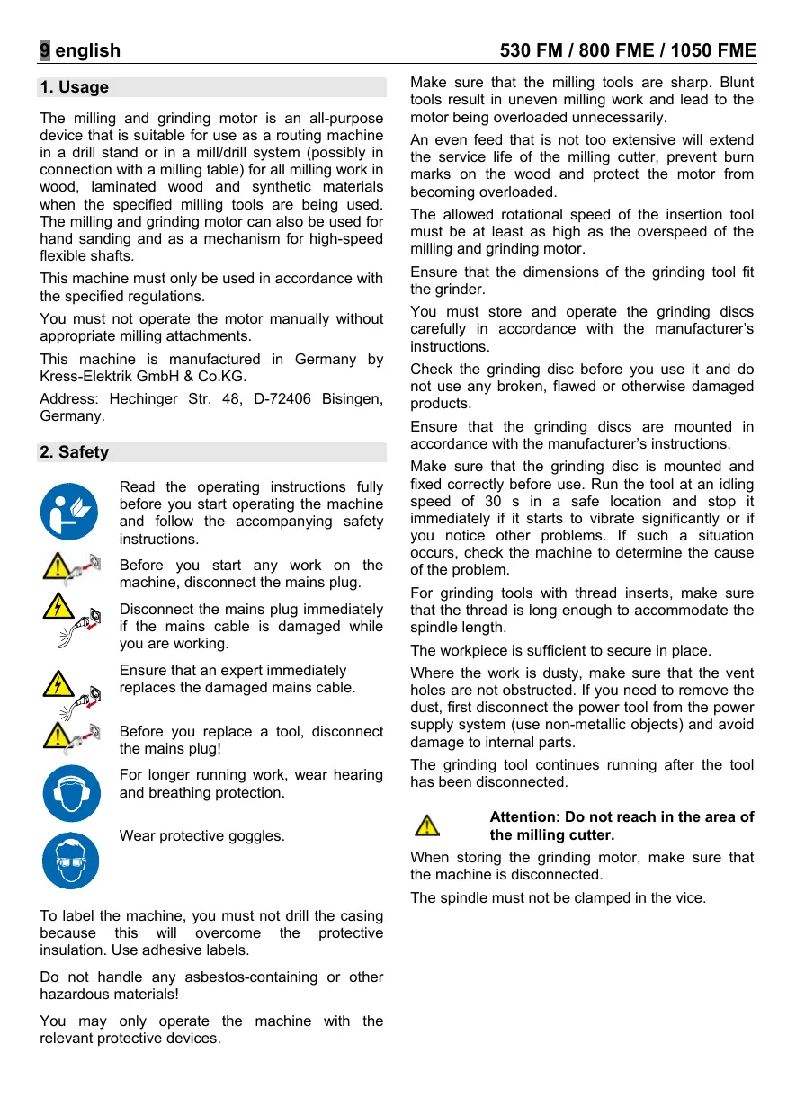
Read the operating instructions fully before you start operating the machine and follow the accompanying safety instructions.

Before you start any work on the machine, disconnect the mains plug.

Disconnect the mains plug immediately if the mains cable is damaged while you are working.

Ensure that an expert immediately replaces the damaged mains cable.

Before you replace a tool, disconnect the mains plug!

For longer running work, wear hearing and breathing protection.

Wear protective goggles.
To label the machine, you must not drill the casing because this will overcome the protective insulation. Use adhesive labels.
Do not handle any asbestos-containing or other hazardous materials!
You may only operate the machine with the relevant protective devices.
Make sure that the milling tools are sharp. Blunt tools result in uneven milling work and lead to the motor being overloaded unnecessarily.
An even feed that is not too extensive will extend the service life of the milling cutter, prevent burn marks on the wood and protect the motor from becoming overloaded.
The allowed rotational speed of the insertion tool must be at least as high as the overspeed of the milling and grinding motor.
Ensure that the dimensions of the grinding tool fit the grinder.
You must store and operate the grinding discs carefully in accordance with the manufacturer's instructions.
Check the grinding disc before you use it and do not use any broken, flawed or otherwise damaged products.
Ensure that the grinding discs are mounted in accordance with the manufacturer's instructions.
Make sure that the grinding disc is mounted and fixed correctly before use. Run the tool at an idling speed of 30 s in a safe location and stop it immediately if it starts to vibrate significantly or if you notice other problems. If such a situation occurs, check the machine to determine the cause of the problem.
For grinding tools with thread inserts, make sure that the thread is long enough to accommodate the spindle length.
The workpiece is sufficient to secure in place.
Where the work is dusty, make sure that the vent holes are not obstructed. If you need to remove the dust, first disconnect the power tool from the power supply system (use non-metallic objects) and avoid damage to internal parts.
The grinding tool continues running after the tool has been disconnected.

Attention: Do not reach in the area of the milling cutter.
When storing the grinding motor, make sure that the machine is disconnected.
The spindle must not be clamped in the vice.
Clamp the milling motor on the clamping collar with a round flange on the entire area (euroneck). Isolated clamping destroys the bearing.
Take into account the specified rotational direction on the motor flange. Hold the device in such a way that the dust caused by the grinding and the flying sparks are away from the body but cannot cause any fire or other damage.
For heavier use, you must clamp the tool on the spindle and locknut using 2 SW 14/17 open-ended spanners.
3. Double insulation
Our machines are built to the highest possible degree of safety for users in accordance with European regulations (EN standards). Double-insulated machines are always labelled with the international l safety symbol. The machines must not be earthed. A two-core cable is sufficient. The machines have interference suppression in accordance with EN 55014.
4. Spare parts/exploded views
For exploded views and lists of spare parts, refer to our home page at http://www.spareparts.kress-elektrik.de.
5. Description of picture
The numbering of the parts of the milling and grinding motor refers to the display on the fold-out page.
- Locknut
- Collet chuck
- Annular spring
- Spindle
- Locking button
- On/off switch
- Speed governor turning wheel
- Mains cable module
- Locking for mains cable module
Accessories displayed or described must not be part of the scope of delivery.
6. Wear parts
| Annular spring | 14348 |
| Collet chuck | 14820 |
| Locknut | 21208 |
| Arresting pin | 35370 |
| Carbon brush | 35635 |
| Mains cable (530 FM/800 FME) | 27794 |
| Mains cable module (1050 FME) | 27280 |
7. Noise/vibration information
Measured values are determined according to EN 50 144.
The A-rated noise level of the machine is typically as follows: sound pressure level 77 dB (A); sound power level 88 dB (A). Measurement uncertainty K = 3 dB.
Wear hearing protection!
The rated speed is typically 11.6m / s2
8. Technical data
| 530 FM | |
| Power consumption | 530 W |
| Power output | 270 W |
| Idling speed | 29,000 min-1 |
| Speed for rated load | 14,300 min-1 |
| Tool fitting with collet chuck Ø | 8 mm |
| Max. grinding tool Ø | 40 mm |
| Max. milling diameter | 30 mm |
| Dimension | 240x73 mm |
| Weight | 1.3 kg |
| Protection class | II / ☐ |
| 800 FME | |
| Power consumption | 800 W |
| Power output | 420 W |
| Idling speed | 10,000–30,000 min-1 |
| Speed for rated load | 25,000 min-1 |
| Tool fitting with collet chuck Ø | 8 mm |
| Max. grinding tool Ø | 40 mm |
| Max. milling diameter | 36 mm |
| Dimension | 262x73 mm |
| Weight | 1.4 kg |
| Protection class | II / ☐ |
| 1050 FME | |
| Power consumption | 1050 W |
| Power output | 560 W |
| Idling speed | 10,000-30,000 min-1 |
| Speed for rated load | 28,300 min-1 |
| Tool fitting with collet chuck Ø | 8 mm |
| Max. grinding tool Ø | 40 mm |
| Max. milling diameter | 36 mm |
| Dimension | 289x73 mm |
| Weight | 1.7 kg |
| Protection class | II / ☑ |
9. Mounting a mains cable module (1050 FME)

Before you start any work on the machine, disconnect the mains plug.
Connect the mains cable module to the machine. The plug must lock into place.
You must not use damaged mains cables. These must be replaced immediately. Press the two locking buttons 9 and disconnect mains cable module 8.
Only use the mains cable module for Kress power tools. Do not attempt to use it with other devices.
Only use original Kress mains cable modules.
10. Before the initial operation
CLAMPING THE TOOLS
The spindle 4 of the milling and grinding motor is equipped with a precision collet chuck 2 to hold the tools. A spindle lock enables you to tighten and loosen the locknut 1. To clamp the tool, you lock the spindle 1 by pressing the locking button 5. You tighten the locknut 1 using a SW 17 open-ended spanner. When you unclamp the tool, the spindle 4 in turn is locked. You loosen the locknut 1 by turning the open-ended spanner. You can remove the tool by continually turning the open-ended spanner.
REPLACING A COLLET CHUCK
An annular spring 3 holds the collet chuck 2 in the locknut 1. By forceful turning, you can loosen the collet chuck 2 from the locknut 1. Press down heavily to lock the new collet chuck into place in the locknut 1.

Caution! Lightly unscrew the locknut to protect the thread on the spindle but never tighten it if a tool is not being used. This might compress the collet chuck too much, which could lead to it becoming damaged.
11. Initial operation

Before you start operating the machine, check whether the mains voltage corresponds to the information on the machine's tool identification plate.
SWITCHING ON THE MACHINE
Push the on/off switch 6 forward until the tilt lever is automatically locked into place.
SWITCHING OFF THE MACHINE
Press down and backwards on the on/off switch 6. The switch returns to the Off position and the machine stops.
12. Operation
WORKING WITH THE MILLING MOTOR


Attention! goggles protection!
Wear and
protective hearing
When you use a drill stand or a mill/drill unit (possibly with a milling table), you must refer to the notes in the instructions for use provided there.
Also note that you must add the alignment fences as far as possible on the milling cutter, the hand deflector (screen) must be set down as tightly as possible on the workpiece surface and, for milling work, you must always use equipment that can guarantee safe use of the tool, for example, alignment fence, auxiliary bearings, automatic feeders or a non-return block for milling work.
The feed direction of the tool must always be the opposite of the circulation direction of the milling cutter (counter direction):


Attention! Always mill in a counter direction!
HANDS-FREE WORK
Due to its low measurements and light weight, the milling and grinding motor is also extremely suitable for a lot of hands-free work. As a milling motor, the machine must only be operated using the appropriate attachments (tray router, laminate trimmers or stationary).
Only use milling, drill, polishing and grinding tools that are approved for high-speed operation (30,000min-1)
GRINDING WORK
When you use the milling and grinding motor as a grinder in a manual operation, you must take into account that the peripheral (circumference) speed must not exceed 80 m / s .
The peripheral (circumference) speed is calculated as follows:
V = dx πxn/6 0 0 0 0
V = Peripheral (circumference) speed m s
d = grinding tool in mm
I = 3. 1 4
n = ldling speed of the milling and grinding motor in revolutions/min.
Example: The grinding tool used has a diameter of 25mm .
V = 2 5 × π × 3 0 0 0 0/6 0 0 0 0 m/s = 3 9. 7 5 m/s
The accepted overspeed is not exceeded. The maximum peripheral (circumference) speed allowed is reached with a grinding tool of 50 mm . You must not use bigger grinding tools.

Attention! After you use the insertion tool, perform a test run with an overspeed and make sure that no-one is within reach of the rotating insertion tool. Damaged tools usually break in this test period.
Make sure that
the grinding tool used is bound with ceramic or resin.
the grinding tools are stored in such a way that they are not damaged (cracks in the grinding tool, damaged tool shanks and so on, mean that the user's life is in danger).
- before you use new grinding tools, you must carry out a test run for at least 5 minutes without the device being overloaded.
In practice

Note! Very high rotational speeds result in the tools wearing rapidly and consequently in low service lives for the tools!

Important! Only use sharp milling tools that are in good condition! Preferably use our original milling tools.
When you use other milling tools, the steady rotational speeds per minute indicated on the manufacturer's rotating tools must not be exceeded!
Subject to change without notice!
WORKING WITH FLEXIBLE SHAFTS
Due to its high rotational speed, the milling and grinding motor is also highly suitable as a drive motor for flexible shafts.
Note here that the maximum rotational speed of the flexible shaft must at least correspond to the rotational speed of the motor.

Attention! Wear protective goggles!
Full-wave electronic regulations (800 FME/ 1050 FME) with electronic motor protection monitoring (safety electronics). The following are integrated into these full-wave electronics with an built-in tachogenerator:
SOFT STARTER
The starting current limitation reduces the starting current. The motor revs up slowly until it reaches the preselected rotational speed. This can extend the service life of the machine.
ELECTRONIC OVERLOAD PROTECTION
With a load that is too high, which therefore implies a risk to the motor, the rotational speed of the milling motor is reduced by the integrated monitoring of the motor. The machine must be released (preferably remove it a short distance from the workpiece) to ensure that you can have full capacity again.
Electronic regulation with tachogenerator
The full-wave electronic regulation allows a large control range of 10,000-30,000 min -1 . If an overload situation occurs, the tachogenerator supplies the power. The preselected rotational speed is constantly adhered to. With the turning wheel 7 of the full-wave electronic regulations, irrespective of
material (for example, hardwood, softwood, synthetics) and
- milling or grinding tool (for example, smaller diameter, lower quality, high quality)
the optimum cutting speed or working rotational speed is used. The required cutting speed or work rotational speed depends on many factors (for example, different hardness of the material to be processed, milling quality, feed, and so on). The best setting should be determined through tests at the beginning of the work.
13. Cleaning and maintenance

Before you start any work on the machine, disconnect the mains plug.
Always keep the ventilation slots unobstructed and clean to guarantee constant ventilation.
- Regularly wipe the outside of synthetic parts with a detergent-free cloth.
After each job, blow the dust from the fan. This will increase your machine's service life.

After extensive operational demands over a longer period of time, the machine should undergo an inspection and thorough cleaning at a Kress service centre.
14. Environmental Protection

Do not dispose of electric tools together with household waste material!
Recycle raw materials instead of disposing as waste
The machine, accessories and packaging should be sorted for environmental-friendly recycling.
These instructions are printed on recycled paper manufactured without chlorine.
The plastic components are labelled for categorised recycling.
1. Utilisation
TRAVAUX AVEC FLEXIBLES
DEMARRAGE PROGRESSIF
TRABAJOS CON EJE FLEXIBLE
n = 3, 1 4
n = 3, 1 4
O Sistema electrónico de regulação de onda completeness, como a magnitude of the system's completeness, is a function of the number of components. The system is composed of a total of n components (10 components per unit) and a total of 2n components per unit. Each component has a value of 0 to 1. The system is also called the system of the system of the system of the system of the system of the system of the system of the system of the system of the system of the system of the system of the system of the system of the system of the system of the system of the system of the system of the system of the system of the system of the system of the system of the system of the system of the system of the system of the system of the system of the system of the system of the system of the system of
Ipeep npoBeDHeMnIObIx pa60tHa npnbOpe BbTaunTb ceTeBOI WTekep.

HemeIeHHo BbItauntce cTeBOI uTekep,ecnB BO BpeM pa60tI NOBpeNTcra cTeBOI Ka6enb.

He 6pa6aTaBbTa b ac6ecToCoedepkauni nn DpyroB BpeHbI dIg 3DOpOBb MaTePnAn!
PpH6Op MoXHO 3KcNJIpyATnPOBaT ToIbKO C OTHOCAUIMNC K HEmy 3aUHTbIMn PnpCnOC6NeHnAIMN.
Cneinte 3a tem, yTo6bI pfpe3epHbI INHCTpymeHT 6bln OCTpbIM. TyNoi INHCTpymeHT BBLIETcR npuHHoH HeTOUHOCTe Ipn Pfpe3epHbIX pa60tax n pInBOIDNT K HEnyHXoN neperpy3Ke DIBrataTeJIA.
PabHOMepnHa n He CnIshKom CnIbHa n oJaHa qpe3epa yBeyIeNHyBaET cPoK CnyJxbl ppe3epa, npdeTBPaUaET NOBHeNe pNkoROB Ha depeBe n 3aunuAET dBIrataTe b OT nepepy3kn.
Donycthmoe YncnO obopotOB DoabOCHoro INCTPYMEnTA DOnJXHO, NO MeHbSei Mepe, BbITb TAKIM JKe BbcOKM, KAK I MaKcImaJIbHOe YNCNO obopotOB ppeepo-UsnPobaIbHORO DBrataTeN.
Y6eIntecb, yTO pa3Mepbl 1JINFOBaJIbHOrO INHCTpymeHTa POJXODaT DnI JNFOBaJIbHO MaJINHbI.
IINIOPOBAJIbHbIE KpyrN CNeJeYeAkkypaTHO XpaHnTb INCNOJIb3OBAtB B COOTBeTCTBm C yka3a-HnRAIM npON3BOdnteJIa.
IpoBepaTe ⅢnDpOBaJIbHbIe Kpyr npeed NCIOB3OBAHmE, He NcOJIb3yIte CnOMaHbIe, IONHyBwIe INI INHbIM oBa3OM nobPexKeHbIe N3dEINIA.
Y6eIntecb, yTO IINFOBaJIbHbIe INHCTpyMeHTbl YcTaHOBJIeHbI CORNaCHO yKa3aHnIaM IpOu3- BOINTeJIa.
I03a60TbTeCb O TOM, yTO6bI nepei nCnOJb3oBAAHEM ⅢNFOBaIbHbI INHCTpMEnT 6blnpAINbHO yCTAHOBNeH I 3aKpeIeH, n DaJIte INHCTpMEnTy NopA60TaTb Ha XOIOCTOM XOyD 30 cekynd B 6e3Oanachom NIOXeHn, cpa3y BblKnIOHTe, eCN NORBATc3HaUNTEbHbIe KONE6aHn nn BydUT BByABHeNb Ipyfne HeNOCTaTKI. Ppi NOrBLeHn TAKoro COCTOHNr pNoBepbTe MaunHy, YTO6bI bIAIBNTb npuHHy.
Y6eIntecb, yTO y BCex UINFOBaJIbHbIX INHCTpyMEHTOB Cpe3b6OBoB BCTaBKo DOCTaTOUHO DInHHaPe3b6a, KOTopa COOTBeTCTByET DInHe UINHNen.
CneNyet Hndnexkaum 06pa3oM 3akpenTb 3arotOBky.
I03a60TbTeCb O TOM, YTO6bI BO BpEmЯ ПьЛьнБИХ pa60t BeHTUNLAIOHNBIE OTBepCTNЯ 6bln OTKpbTbI. Ecnn NOTpe6yETcYdANITb Nbl, Cha7aJIa OTCOeHNHTE 3NEKTPoHNCTpyMeNT OT 3NEKTPoHNTaHNI (NcNoJIb3yJTe HEmetAnLIueckne 6bEketb), N36eRaIte NOBpeXJdeH NByTpEHnX qacteI.
Iocne OTKnOHeHnIHCTpymeHaTbNIOPOBaJIbHbI INHCTpymeHT npoDoJkaet BpaaTaBc.

BHHMaHHe:He npOraRnBaTb pyKn B30HyΦpe3epa.
Chmma qpe3epnbl DbVraTeJIb, cneIte 3a TeM, yTo6bl np6bp6bl OTKJIOUeH.
IIHHneIb He DoJIkeH 6bITb 3aKaT B TnCKaX.
3aXmIte 4pe3epHbI DnBirateJIb B 3aXmHNoi
WeKe NocpeDCTBOM KpyrNoro 0naHua NO BCEmy
nepImeTp (eBPO-WeKa).ToueHbI 3axm pa3p
pywaet POnUnnHnK.
Ioxaunycta, cneinte 3a yka3aHbIM HnpaBHeHem BpaueHnna DnurTaTena. Depknte np6op Tak, YTObbluINFOBaBnA HnbN uNCKpbI He nonadaHn Ha TeNo, nHaue OHN MOrY CTaTb npUHHo NpOxapa nn dpynx NOpeXdeHn.
B Tpyndbix Cnyaay HNCTpymENT Heo6xOdmo 3axaTb npn nomoun 2 raeuHbIX KJIouye C OTKpbI- TbIM 3ebOM SW14/17 Ha uHHdeJe N 3aXmHOn raKe.
3.ДвовнаиЗолЯця.
Haun npnbopby pa3pa60TaHbI c zelbO MaKcMnMaJbHO B03MOxHoi 6e3oNaChOCTn NOJIb3OBaTeNBA COOTBeTCTBmC EBPOeNCKMn PpeDnCaHnIMn (CTaNDapTAMN EC). MaunHbI C DBOHNO H3OJIaueB CEGda NMEOT MExdYnapDHyO MapKnPobKy. MaunHbI He 3a3eMnTb. DoCTaTOUHO NCNoJb3OBaTb DByXnJIbHbI Ka6eIb. MaunHa BV NCKpOzAunuJeHHOM NCNoJIHeHHn CORnaCHO CTaNdApTy EN 55014.
4. 3anachbte yactn / nOKOMnoHHTHOe n3o6paxeHne
N3o6paXeHHbI NnONcaHHbI npHaJLJIeKHOCTN He DOJIaXHbI BXOaNTb B KOMJIeKT NOCTaBKn.
IpeepocyuaceCTBJIeHnEMJIIObIXpa60T C npnbopom BbITaUHTe CeTeBOI uTEkep.
IopknHouHTe K npBOpy MoDyIb ceTeBOrO Ka6eIa.
IteKepe DOnJKeH 3aUeNkHyTbcr.
He nCnoIb3ObaTb NOBpeXeHnHbI cTeBoi Ka6eIb. Ero CneJeYeT He3aMeIaNTeIbHo 3aMeHnTb. HaxaTb o6 bLOKIpOBoUHbI KHOJI K N BblTaUHTb MoDyIb cTeBOrO Ka6eJI8.
IcnoIb3yIte MoJyIbe cTeBoro Ka6eIa ToJIbKO dIra 3JIeKToPiHCTpyMeHTa QnPmbl Kress. He nbItai-TEcB 3KcNIIyaTnPOBaTb C Hm DpyrIe npIbOpbl.
IcnoIb3yIte TOnIbKO opnHaJIbHbIe MoUyn CTeBoro Ka6eJI qIpMbI Kress.
Piv n 8ieaywyn twv epyaiov ot n mXavn, aTTOOUVoTe to BuOa TPOPOooiaoc.

Eav, otn diapkeia twv epyaoiwv, uTOOTe zmu to KAALWIO TPOPOOOIac, aTOOUVDEOEaEOwG TO BUGa TPOPOOOIac.

Znntne aea tny avtikataoan tou kateotpamevou kaawoiu ato KaTIOv EIKO.

Pniv Tny aalayntou epyaieiou, aTTOOuvOeTeToBuaTPOpOoOiaC!
EPRAIA ME EAEYOEPA TA XEPIA
H mnxavn qpezapiauatos kai eiavans eivai, loyw twv miipwov iaotaeew tnq kai tou elaxiotou bapouc ts, ioiitepa katalkan yia TOnAe cypaaie cE eLeutheta pa ta xepia. Os mnxavn qpezapiauotos, pTeTI VA xpnaioTpoieitai movo tC KATALANe C Tpoo0hke (Baon kaetns qpezac, Tpoo0hkn yia qpezapiaumaakuw n otatiko).
XpnoiouoieIe mOvo epyaia qpezapiauatoC, diatponc, otlaawonkai laivons, ta oioia evai ykekiéva yia aietoupyia oe uynAES taxutntes (30.000 min-1).
EPΓΑΣΙΕΣ ΛΕΙΝΗΣ
n = 3, 1 4
- This electrical tool has been designed with high precision and was approved after undergoing strict quality control checks in the factory.
- We are therefore able to guarantee free servicing of any production or material faults which arise in the 24 months after the date of sale to the purchaser. We reserve the right to repair defective parts or else replace them with new parts. Parts which have been replaced become our property.
- The guarantee will be rendered void if the device is used improperly, mistreated or opened up by unauthorised repair personnel. Parts which are subject to wear are not covered by the guarantee.
- The guarantee may only be enforced when defects are reported without undue delay (including shipping damage). Guarantee implementation does not extend the guarantee period.
- If the tool is defective, please complete the guarantee card and return the unit, guarantee card and a brief description of the problem to the responsible service location. Please enclose your sales receipt.
- The guarantee obligations assumed by us shall exclude any further claims on the part of the buyer, in particular the right to recission of a sale, reduction and the assertion of damage claims.
- However, the buyer shall have the right to either a reduction (in the purchase price) or the recission of the sale (cancellation of the sales agreement) should we fail to eliminate any defects within a reasonable period of time.
- Damage claims in accordance with §§ 463, 480 Paragraph 2, 635 BGB due to absence of guaranteed quality shall not be excluded.
- The provisions defined in Items 7 and 8 only apply to the Federal Republic of Germany.
F Garantie
GB CE Declaration of conformity
We declare under our sole responsibility that this product is in conformity with the following standards or standardization documents: see below
GE CE AnwOn OuaOaTkoTnToC
Anwovoue UTUEUVOWOS TOI TPOIOV auto Eival KATAOKEAUOVEOUMFWVA ME TOUs EIGKAVOVIOUc N kataOKEAOTIKES OUATAEIC: BAETTE KATW

ME77
GOST R
TOCT 12.2.013.0-91 (M3K 745-1-82)
TOCT P 30699-2001 (M3K 745-2-17-89)
FOCT 12.2.030-2000, FOCT 17770-86
TOCT P 51317.3.2-99.
TOCT P 51317.3.3-99.
TOCT P 51318.14.1-99
CeptnnФКAT COOTBETCTBNA
No POCC DE.ME77.B02991
CpOK DeIcTBnA C
05.05.2005 r. no 05.05.2008 r.
EN 50144-2-3.
EN 55014-1, EN 55014-2, EN 61000-3-2, EN 61000-3-3
98/37/EG, 89/336/EWG
KRESS-elektrik GmbH & Co.KG, D-72406 Bisingen
Manager Current Product
Manager Current Product

Josef Leins
Quality Assurance Manager
Quality Assurance Manager
Service-Anschriften/After sales service/Service après-vente
Westcross Centre, 15 Shield Drive
Brentford TW8 9EX
Phone: +44-(0)208-560 0885
Telefax: +44-(0)208-847 0790
E-mail: njtoolsbrentford@btopenworld.com
France:
S.A.R.L. Induba
Nachimoyskyi prospect. 48
RU-117292 Moskau
Phone/Fax: +7 (0)95 - 741 25 17
Phone/Fax: +7 (0)95 - 125 17 25
E-mail: danga@globonet.ru


http://www.kress-elektrik.de
http:// spareparts.kress-elektrik.de

Garantie-Karte Warranty card Bon de Garantie
- SAFETY
- ATTENTION: DO NOT REACH IN THE AREA OF THE MILLING CUTTER
- DOUBLE INSULATION
- SPARE PARTS/EXPLODED VIEWS
- DESCRIPTION OF PICTURE
- WEAR PARTS
- NOISE/VIBRATION INFORMATION
- WEAR HEARING PROTECTION
- TECHNICAL DATA
- MOUNTING A MAINS CABLE MODULE (1050 FME)
- BEFORE THE INITIAL OPERATION
- CLAMPING THE TOOLS
- REPLACING A COLLET CHUCK
- INITIAL OPERATION
- SWITCHING ON THE MACHINE
- SWITCHING OFF THE MACHINE
- OPERATION
- WORKING WITH THE MILLING MOTOR
- HANDS-FREE WORK
- GRINDING WORK
- MAKE SURE THAT
- IN PRACTICE
- SUBJECT TO CHANGE WITHOUT NOTICE
- WORKING WITH FLEXIBLE SHAFTS
- ATTENTION! WEAR PROTECTIVE GOGGLES
- SOFT STARTER
- ELECTRONIC OVERLOAD PROTECTION
- ELECTRONIC REGULATION WITH TACHOGENERATOR
- CLEANING AND MAINTENANCE
- ENVIRONMENTAL PROTECTION
- UTILISATION
- TRAVAUX AVEC FLEXIBLES
- DEMARRAGE PROGRESSIF
- TRABAJOS CON EJE FLEXIBLE
- BHHMAHHE:HE NPORARNBATB PYKN B30HYΦPE3EPA
- 3.ДВОВНАИЗОЛЯЦЯ
- 3ANACHBTE YACTN / NOKOMNOHHTHOE N3O6PAXEHNE
- EPRAIA ME EAEYOEPA TA XEPIA
- EPΓΑΣΙΕΣ ΛΕΙΝΗΣ
- F GARANTIE
- GB CE DECLARATION OF CONFORMITY
- GE CE ANWON OUAOATKOTNTOC
- HTTP://WWW.KRESS-ELEKTRIK.DE
- HTTP:// SPAREPARTS.KRESS-ELEKTRIK.DE
- GARANTIE-KARTE WARRANTY CARD BON DE GARANTIE
Brand : KRESS
Model : 800 FME
Category : Power tool