
HGCA3000 - Electric generator HOMELITE - Free user manual and instructions
Find the device manual for free HGCA3000 HOMELITE in PDF.
| Product type | Electric generator |
| Brand | HOMELITE |
| Model | HGCA3000 |
| Dimensions (L x W x H) | 610 x 432 x 457 mm |
| Weight | 46 kg |
| Engine | 6.5 HP, OHV, 4-stroke |
| Start type | Recoil start |
| Recommended engine oil | SAE 10W-30, volume 0.61 L |
| Fuel tank capacity | 15.1 L (4 gallons) |
| Rated voltage | 120 V AC |
| Rated frequency | 60 Hz |
| Rated / maximum power | 3000 W / 3500 W |
| Rated amperage | 20 A / 25 A |
| Outlets | 1 x duplex 120 V 20 A, 2 x locking 120 V 30 A |
| Digital display | Voltage, frequency, operating hours, low oil alert |
| Safety devices | AC circuit breaker, low oil sensor, spark arrestor |
| Grounding | Grounding terminal on frame, 8 AWG wire recommended |
| Periodic maintenance | Oil change every 50 h, air filter every 20 h, spark plug every 100 h |
| Warranty | 2 years residential use, 1 year commercial use |
| Usage | Outdoor only, away from windows and doors |
Frequently Asked Questions - HGCA3000 HOMELITE
User questions about HGCA3000 HOMELITE
0 question about this device. Answer the ones you know or ask your own.
Ask a new question about this device
Download the instructions for your Electric generator in PDF format for free! Find your manual HGCA3000 - HOMELITE and take your electronic device back in hand. On this page are published all the documents necessary for the use of your device. HGCA3000 by HOMELITE.
USER MANUAL HGCA3000 HOMELITE
Your generator has been engineered and manufactured to our high standard for dependability, ease of operation, and operator safety. When properly cared for, it will give you years of rugged, trouble-free performance.

DANGER: You WILL be KILLED or SERIOUSLY HURT if you do not follow the instructions in this operator's manual.
Thank you for your purchase.
SAVE THIS MANUAL FOR FUTURE REFERENCE
See this fold-out section for all of the figures referenced in the operator's manual.
Introduction 2
Important Safety Instructions 3-4
Specific Safety Rules 4
Symbols 5-7
■ Electrical 8-9
Features 10
Assembly 11-12
Operation 12-14
■ Maintenance 15-17
Troubleshooting 18
■ Warranty. 19
Parts Ordering / Service. Back Page
INTRODUCTION
This product has many features for making its use more pleasant and enjoyable. Safety, performance, and dependability have been given top priority in the design of this product, making it easy to maintain and operate.

DANGER:
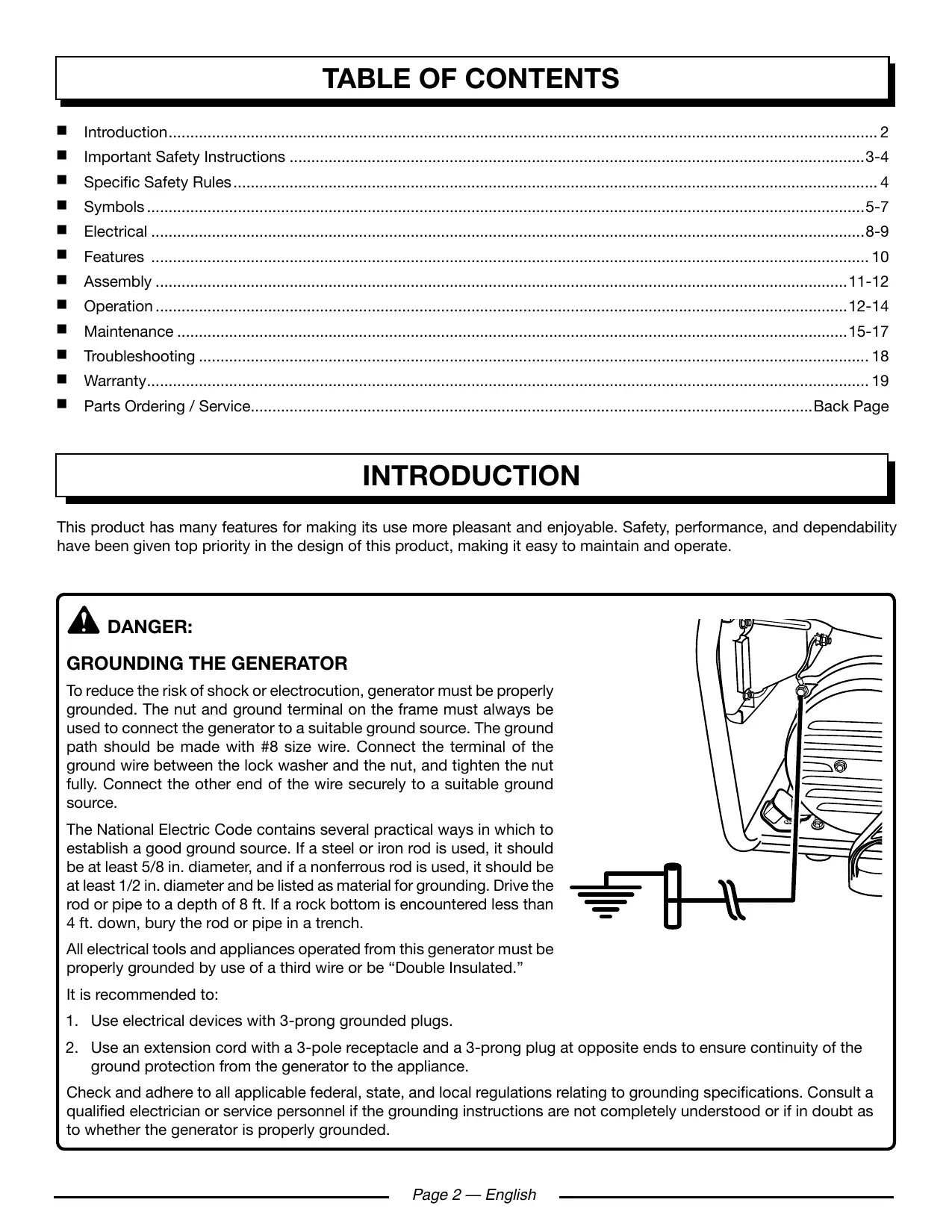
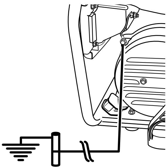
GROUNDING THE GENERATOR
To reduce the risk of shock or electrocution, generator must be properly grounded. The nut and ground terminal on the frame must always be used to connect the generator to a suitable ground source. The ground path should be made with #8 size wire. Connect the terminal of the ground wire between the lock washer and the nut, and tighten the nut fully. Connect the other end of the wire securely to a suitable ground source.
The National Electric Code contains several practical ways in which to establish a good ground source. If a steel or iron rod is used, it should be at least 5/8 in. diameter, and if a nonferrous rod is used, it should be at least 1/2 in. diameter and be listed as material for grounding. Drive the rod or pipe to a depth of 8 ft. If a rock bottom is encountered less than 4 ft. down, bury the rod or pipe in a trench.
All electrical tools and appliances operated from this generator must be properly grounded by use of a third wire or be "Double Insulated."
It is recommended to:
- Use electrical devices with 3-prong grounded plugs.
- Use an extension cord with a 3-pole receptacle and a 3-prong plug at opposite ends to ensure continuity of the ground protection from the generator to the appliance.
Check and adhere to all applicable federal, state, and local regulations relating to grounding specifications. Consult a qualified electrician or service personnel if the grounding instructions are not completely understood or if in doubt as to whether the generator is properly grounded.
IMPORTANT SAFETY INSTRUCTIONS

DANGER:
Carbon Monoxide. Using a generator indoors CAN KILL YOU IN MINUTES.
Generator exhaust contains high levels of carbon monoxide (CO), a poisonous gas you cannot see or smell. If you can smell the generator exhaust, you are breathing CO. But even if you cannot smell the exhaust, you could be breathing CO.
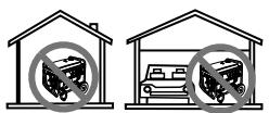
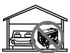
- Never use a generator inside homes, garages, crawl-spaces, or other partly enclosed areas. Deadly levels of carbon monoxide can build up in these areas. Using a fan or opening windows and doors does NOT supply enough fresh air.
- ONLY use a generator outdoors and far away from open windows, doors, and vents. These openings can pull in generator exhaust.
Even when you use a generator correctly, CO may leak into the home. ALWAYS use a battery-powered or battery-backup CO alarm in the home.
If you start to feel sick, dizzy, or weak after the generator has been running, move to fresh air RIGHT AWAY. See a doctor. You could have carbon monoxide poisoning.

WARNING:
Read and understand all instructions. Failure to follow all instructions listed below may result in electrocution, fire, and/or carbon monoxide poisoning, which will cause death or serious injury.

WARNING:
National Electric Code requires generator to be grounded to an approved earth ground. Before using the ground terminal, consult a qualified electrician, electrical inspector, or local agency having jurisdiction for local codes or ordinances that apply to the intended use of the generator.
SAVE THESE INSTRUCTIONS
This manual contains important instructions that should be followed during installation and maintenance of the generator and batteries.
- Do not connect to a building's electrical system unless the generator and transfer switch have been properly installed and the electrical output has been verified by a qualified electrician.
-
Do not allow children or untrained individuals to use this unit.
-
Never start or run the engine inside a closed or partially enclosed area. Breathing exhaust fumes will kill you.
Always wear eye protection with side shields marked to comply with ANSI Z87.1 as well as hearing protection when operating this equipment. - Keep all bystanders, children, and pets at least 10 feet away.
Wear sturdy and dry shoes or boots. Do not operate while barefoot. - Do not operate generator when you are tired or under the influence of drugs, alcohol, or medication.
- Keep all parts of your body away from any moving parts and all hot surfaces of the unit.
- Do not touch bare wire or receptacles.
- Do not use generator with electrical cords which are worn, frayed, bare, or otherwise damaged.
Before storing, allow the engine to cool and drain fuel from the unit. - Do not operate or store the generator in rain, snow, or wet weather.
- Store the generator in a well-ventilated area with the fuel tank empty. Fuel should not be stored near the generator.
- Empty fuel tank, close fuel valve, and restrain the unit from moving before transporting in a vehicle.
■ Allow engine to cool for five minutes before refueling.
To reduce the risk of fire and burn injury, handle fuel with care. It is highly flammable. - Do not smoke while handling fuel.
Store fuel in a container approved for gasoline.
Position the unit on level ground, stop engine, and allow to cool before refueling. - Loosen fuel cap slowly to release pressure and to keep fuel from escaping around the cap.
Tighten the fuel cap securely after refueling.
Wipe spilled fuel from the unit. - Never attempt to burn off spilled fuel under any circumstances.
- Generators vibrate in normal use. During and after the use of the generator, inspect the generator as well as extension cords and power supply cords connected to it for damage resulting from vibration. Have damaged items repaired or replaced as necessary. Do not use plugs or cords that show signs of damage such as broken or cracked insulation or damaged blades.
- For power outages, permanently installed stationary generators are better suited for providing back-up power to the home. Even a properly connected portable generator can become overloaded. This may result in overheating or stressing the generator components, possibly leading to generator failure.
IMPORTANT SAFETY INSTRUCTIONS
-
Use only authorized replacement parts and accessories and follow instructions in the Maintenance section of this manual. Use of unauthorized parts or failure to follow maintenance instructions may create a risk of shock or injury.
-
Maintain the unit per maintenance instructions in this Operator's Manual.
■ Inspect the unit before each use for loose fasteners, fuel leaks, etc. Replace damaged parts.
SPECIFIC SAFETY RULES

WARNING:
When this generator is used to supply a building wiring system: generator must be installed by a qualified electrician and connected to a transfer switch as a separately derived system in accordance with NFPA 70, National Electrical Code. The generator shall be connected through a transfer switch that switches all conductors other than the equipment grounding conductor. The frame of the generator shall be connected to an approved grounding electrode. Failure to isolate the generator from power utility can result in death or injury to electric utility workers.
Exhaust contains poisonous carbon monoxide, a colorless, odorless gas. Breathing exhaust can cause loss of consciousness and can lead to death. If running in a confined or partially-enclosed area, the air may contain a dangerous amount of carbon monoxide. To keep exhaust fumes from building up, always provide adequate ventilation.
Always use a battery-powered carbon monoxide detector when running the generator. If you begin to feel sick, dizzy, or weak while using the generator, shut it off and get to fresh air immediately. See a doctor. You may have carbon monoxide poisoning.
Place the generator on a flat, stable surface.
- Operate in a well-ventilated, well-lit area isolated from working areas to avoid noise interference.
- Operating the generator in wet conditions could result in electrocution. Keep the unit dry.
- Keep the generator a minimum of 3 feet away from all types of combustible material.
- Do not operate generator near hazardous material.
- Do not operate generator at a gas or natural gas filling station.
- Do not touch the muffler or cylinder during or immediately after use; they are HOT and will cause burn injury.
This generator has a neutral bonded condition. This means the neutral conductor is electrically connected to the frame of the machine.
- Do not allow the generator's gas tank to overflow when filling. Fill to 1 in. below the top neck of the gasoline tank to allow for fuel expansion. Do not cover the fuel tank cap when the engine is running. Covering the fuel tank cap during use may cause engine failure and/or damage to the tool.
- Do not smoke when filling the generator with gasoline.
- Shut down the engine and allow to cool completely before adding gasoline or lubricant to the generator.
- Do not remove the oil dipstick or the fuel tank cap when the engine is running.
Pay close attention to all safety labels located on the generator.
- Keep children a minimum of 10 feet away from the generator at all times.
The unit operates best in temperatures between 23^ F and 104^ F with a relative humidity of 90% or less.
- Specific modifications for high-altitude performance are needed if the generator will always be operated at altitudes above 5,000 feet. Contact your nearest authorized service center for more information and to have these modifications performed.
- Operating voltage and frequency requirement of all electronic equipment should be checked prior to plugging them into this generator. Damage may result if the equipment is not designed to operate within a +/- 10% voltage variation, and +/- 3 Hz frequency variation from the generator name plate ratings. To reduce the risk of damage, always have an additional load plugged into the generator if solid state equipment (such as a television set) is used. A power line conditioner is recommended for some solid state applications.
- Save these instructions. Refer to them frequently and use them to instruct others who may use this product. If you loan someone this product, loan them these instructions also.
SYMBOLS
| The following signal words and meanings are intended to explain the levels of risk associated with this product. | ||
| SYMBOL | SIGNAL | MEANING |
| A | DANGER: | Indicates an imminently hazardous situation, which, if not avoided, will result in death or serious injury. |
| A | WARNING: | Indicates a potentially hazardous situation, which, if not avoided, could result in death or serious injury. |
| A | CAUTION: | Indicates a potentially hazardous situation, which, if not avoided, may result in minor or moderate injury. |
| A | CAUTION: | (Without Safety Alert Symbol) Indicates a situation that may result in property damage. |
| Some of the following symbols may be used on this product. Please study them and learn their meaning. Proper interpretation of these symbols will allow you to operate the product better and safer. SYMBOL NAME DESIGNATION/EXPLANATION | ||
| Safety Alert | Indicates a potential personal injury hazard. | |
| Read Operator's Manual | To reduce the risk of injury, user must read and understand operator's manual before using this product. | |
| Wet Conditions Alert | Do not expose to rain or use in damp locations. | |
| Electric Shock | Failure to use in dry conditions and to observe safe practices can result in electric shock. | |
| Toxic Fumes | Running generator gives off carbon monoxide, an odorless, color-less, poison gas. Breathing carbon monoxide can cause nausea, fainting, or death. | |
| Fire/Explosion | Fuel and its vapors are extremely flammable and explosive. Fire or explosion can cause severe burns or death. | |
| Hot Surface | To reduce the risk of injury or damage, avoid contact with any hot surface. | |
| Lifting Hazard | To reduce the risk of serious injury, avoid attempting to lift the generator alone. | |
| Ground | Consult with local electrician to determine grounding requirements before operation. | |
| Electrocution | Failure to properly ground generator can result in electrocution, especially if the generator is equipped with a wheel kit. | |
SYMBOLS
| Some of the following symbols may be used on this product. Please study them and learn their meaning. Proper interpretation of these symbols will allow you to operate the product better and safer. SYMBOL NAME DESIGNATION/EXPLANATION | ||
| V | Volts | Voltage |
| A | Amperes | Current |
| Hz | Hertz | Frequency (cycles per second) |
| W | Watt | Power |
| hrs | Hours | Time |
| gal | Gallon | Volume |
| qt | Quart | Volume |
SAFETY LABELS
The information below can be found on the generator. For your safety, please study and understand all of the labels before starting the generator.
If any of the labels come off the unit or become hard to read, contact an authorized service center for replacement.
DANGER
Using a generator indoors CAN KILL YOU IN MINUTES. Generator exhaust contains carbon monoxide. This is a poison you cannot see or smell.
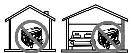
NEVER use inside a home or garage, EVEN IF doors and windows are open.

Only use OUTSIDE and far away from windows, doors, and vents.
DANGER
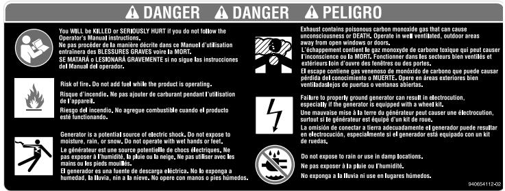
- You WILL be KILLED or SERIOUSLY HURT if you do not follow the Operator's Manual instructions.
■ Risk of Fire. Do not add fuel while the product is operating. - Generator is a potential source of electric shock. Do not expose to moisture, rain, or snow. Do not operate with wet hands or feet.
Exhaust contains poisonous carbon monoxide gas that can cause unconsciousness or DEATH. Operate in well-ventilated, outdoor areas away from open windows or doors.
Failure to properly ground generator can result in electrocution, especially if the generator is equipped with a wheel kit. - Do not expose to rain or use in damp locations.
Using a generator indoors CAN KILL YOU IN MINUTES. Generator exhaust contains carbon monoxide. This is a poison you cannot see or smell.
NEVER use inside a home or garage, EVEN IF doors and windows are open. - Only use OUTSIDE and far away from windows, doors, and vents.
FUEL WARNING
No smoking when filling with gasoline. Do not overfill. Full level is 1 in. below the top of the fuel neck. Stop the engine for five minutes before refueling to avoid the heat from the muffler igniting fuel vapors.
ENGINE LUBRICANT WARNING
You must add lubricant before first operating the generator. The oil reservoir capacity is 0.64 qt. Always check the lubricant level before each operation. The lubricant level should always register between the hatched areas on the dipstick. The unit is equipped with a sensor which will automatically shut off the engine if the lubricant level falls below a safe limit.
GROUNDING WARNING
National Electric Code requires generator to be grounded to an approved earth ground.
WARNING AVERTISSEMENT ADVERTENCIA
Product does not include ground rod or copper wire. National Electric Code requires generator to be properly grounded to an approved earth ground. Call an electrician for local grounding requirements.
Add lubricant to full mark to start. Engine will not start or will shut off if lubricant is too low.
WARNING Operation of this equipment may create sparks that can start fires around dry vegetation. A spark arrester may be required. The operator should contact local fire agencies for laws or regulations relating to fire prevention requirements.
Do not touch the muffler or aluminum cylinder of the engine. They are very HOT and will cause severe burns. Don't put any flammable or combustible materials in the direct path of the exhaust.
ELECTRICAL
EXTENSION CORD CABLE SIZE
Refer to the table below to ensure the cable size of the extension cords you use are capable of carrying the required load. Inadequate size cables can cause a voltage drop, which can damage the appliance and overheat the cord.
| Current in Amperes | Load in Watts | Maximum Allowable Cord Length | |||||
| At 120V | At 240V | #8 Wire | #10 Wire | #12 Wire | #14 Wire | #16 Wire | |
| 2.5 | 300 | 600 | 1000 ft. | 600 ft. | 375 ft. | 250 ft. | |
| 5 | 600 | 1200 | 500 ft. | 300 ft. | 200 ft. | 125 ft. | |
| 7.5 | 900 | 1800 | 350 ft. | 200 ft. | 125 ft. | 100 ft. | |
| 10 | 1200 | 2400 | 250 ft. | 150 ft. | 100 ft. | 50 ft. | |
| 15 | 1800 | 3600 | 150 ft. | 100 ft. | 65 ft. | ||
| 20 | 2400 | 4800 | 175 ft. | 125 ft. | 75 ft. | ||
| 25 | 3000 | 6000 | 150 ft. | 100 ft. | |||
| 30 | 3600 | 7200 | 125 ft. | 65 ft. | |||
| 40 | 4800 | 9600 | 90 ft. | ||||
ELECTRIC MOTOR LOADS
It is characteristic of common electric motors in normal operation to draw up to six times their running current while starting. This table may be used to estimate the watts required to start "Code G" electric motors; however, if an electric motor fails to start or reach running speed, turn off the appliance or tool immediately to avoid equipment damage. Always check the requirements of the tool or appliance being used compared to the rated output of the generator.
| Motor Size (H.P.) | Running Watts | Watts Required to Start Motor | ||
| Repulsion Induction | Capacitor | Split Phase | ||
| 1/8 | 275 | 600 | 850 | 1200 |
| 1/6 | 275 | 600 | 850 | 2050 |
| 1/4 | 400 | 850 | 1050 | 2400 |
| 1/3 | 450 | 975 | 1350 | 2700 |
| 1/2 | 600 | 1300 | 1800 | 3600 |
| 3/4 | 850 | 1900 | 2600 | - |
| 1 | 1100 | 2500 | 3300 | - |
CAUTION:
Operating voltage and frequency requirement of all electronic equipment should be checked prior to plugging them into this generator. Damage may result if the equipment is not designed to operate within a +/- 10% voltage variation, and +/- 3 Hz frequency variation from the generator name plate ratings. To avoid damage, always have an additional load plugged into the generator if solid state equipment (such as a television set) is used. A power line conditioner is recommended for some solid state applications.
GENERATOR CAPACITY
Make sure the generator can supply enough continuous (running) and surge (starting) watts for the items you will power at the same time. Follow these simple steps.
- Select the items you will power at the same time.
- Total the continuous (running) watts of these items. This is the amount of power the generator must produce to keep the items running. See the wattage reference chart at right.
- Estimate how many surge (starting) watts you will need. Surge wattage is the short burst of power needed to start electric motor-driven tools or appliances such as a circular saw or refrigerator. Because not all motors start at the same time, total surge watts can be estimated by adding only the item(s) with the highest additional surge watts to the total rated watts from step 2.
Example:
| Tool or Appliance | Continuous (Running) Watts | Surge (Starting) Watts |
| Window AC, 10,000 BTU | 1200 | 1800 |
| Refrigerator | 700 | 2200 |
| 1/3 HP Well Pump | 1000 | 2000 |
| 27 in. Television | 500 | 0 |
| Light (75 Watts) | 75 | 0 |
| 3475 Total Running Watts | 2200 Highest Surge Watts |
Total Continuous (Running) Watts 3475
Plus Highest Additional Surge Watts +2200
Equals Total Generator Output Required 5675
POWER MANAGEMENT
To prolong the life of the generator and attached devices, it is important to take care when adding electrical loads to the generator. There should be nothing connected to the generator outlets before starting its engine. The correct and safe way to manage generator power is to sequentially add loads as follows:
- With nothing connected to the generator, start the engine as described later in this manual.
- Plug in and turn on the first load, preferably the largest load you have.
- Permit the generator output to stabilize (engine runs smoothly and attached device operates properly).
- Plug in and turn on the next load.
- Again, permit the generator to stabilize.
- Repeat steps 4 and 5 for each additional load.
Never add more loads than the generator capacity. Take special care to consider surge loads in generator capacity as previously described.
CAUTION:
Do not overload the generator's capacity. Exceeding the generator's wattage/amperage capacity can damage the generator and/or electrical devices connected to it.
| Application/Equipment | Estimated Run Watts | Estimated Starting Watts |
| Emergency / Home Standby | ||
| Clock Radio | 50 | 50 |
| Lights (qty. 4 x 75 W) | 300 | 300 |
| Refrigerator | 700 | 2200 |
| Furnace Fan | 800 | 2350 |
| Water Well Pump | 1000 | 1500 |
| Microwave | 1000 | 1000 |
| Sump Pump | 1050 | 2200 |
| Electric Range (per element) | 2100 | 2100 |
| Job Site | ||
| Electric Drill – 1/2 HP | 600 | 900 |
| Airless Sprayer – 1/3 HP | 600 | 1200 |
| Quartz Halogen Work Light | 1000 | 1000 |
| Reciprocating Saw | 960 | 1920 |
| Air Compressor – 1 HP | 1600 | 4500 |
| Circular Saw – 7-1/4 in. | 1400 | 2300 |
| Planer/Jointer – 6 in | 1800 | 1800 |
| Miter Saw – 10 in. | 1800 | 1800 |
| Table Saw/Radial Arm Saw – 10 in. | 2000 | 2000 |
*Wattages listed are approximate. Check tool or appliance for actual wattage.
FEATURES
PRODUCT SPECIFICATIONS
ENGINE
Engine Type. 6.5 HP OHV
Cooling System . Forced Air
Starting System.
Ignition System. T.C.I.
Spark Plug... Champion N64Y
Engine Lubricant Volume. 0.64 qt.
Fuel Volume. 4 gal.
GENERATOR
Rated Voltage 120V
RatedAmps. 20A/25A
Rated Output. 3,000 W
Maximum Output. 3,500 W
Rated Frequency. 60 Hz
DIMENSIONS
Length 24 in.
Width 17 in.
Height 18 in.
Weight 101.5 lbs.
KNOW YOUR GENERATOR
See Figure 1.
The safe use of this product requires an understanding of the information on the product and in this operator's manual as well as a knowledge of the project you are attempting. Before use of this product, familiarize yourself with all operating features and safety rules.
AC CIRCUIT BREAKERS
The circuit breakers are provided to protect the generator against electrical overload. The circuit breaker may be reset by pressing the circuit breaker reset button.
AIR FILTER
The air filter helps to limit the amount of dirt and dust drawn into the unit during operation.
AIR INTAKE VALVE
This unit is equipped with an air intake valve to help improve engine performance during colder winter temperatures.
CHOKE LEVER
The choke lever is used when starting the engine.
DIGITAL DISPLAY
The digital display shows the voltage, frequency, the hour meter and the low lubricant alert.
FUEL TANK
The fuel tank has a capacity of 4 gallons.
FUEL VALVE
The flow of fuel through the generator is controlled by the position of the fuel valve.
GROUND TERMINAL
The ground terminal is used to assist in properly grounding the generator to help protect against electrical shock. Consult with a local electrician for grounding requirements in your area.
OIL CAP
Remove the oil fill cap to check and add lubricant to the generator when necessary.
OIL DRAINAGE BOLT
When changing the engine lubricant, the oil drainage bolt is loosened to allow old engine lubricant to be drained.
RECEPTACLES
Your generator has the following single phase, 60Hz outlets: one 120 Volt AC, 20 Amp duplex receptacle, and two 120 Volt AC, 30 Amp twist-lock receptacles. These can be used for operating appropriate appliances, electrical lighting, tools, and motor loads.
RECOIL STARTER GRIP
The recoil starter grip is used (along with the engine switch) to start the generator's engine.
ASSEMBLY

WARNING:
Do not attempt to operate the generator until assembly is complete. Failure to comply could result in possible serious personal injury.
LOOSE PARTS LIST
See Figure 2.
The following items are included with the generator:
Key
No. Description Qty.
1 Bolts (M10 x 17 mm) .2
2 Spacers 2
3 Lock Nuts (M8) 3
4 Wheel Covers 2
5 Wheels. 2
6 Lock Nuts (M10) 2
7 Rubber Feet. 2
8 Bolt (M8× 20mm)
9 Bolt (M8 x 40 mm)
10 Handle Assembly. 1
11 Handle Lock Pin 1
12 Lanyard. 1
13 Bottle of Engine Lubricant. 1
Operator's Manual (not shown) 1
TOOLS NEEDED
See Figure 3.
The following tools (not included or drawn to scale) are needed for assembly:
- Socket Wrench (12 mm and 13 mm)
Combination Wrench (10 mm, 12 mm, 13 mm, and 14 mm)
NOTE: Do not put fuel or lubricant in the generator before installing the legs and wheels.
UNPACKING
This product requires assembly.
- Carefully cut the box down the sides then remove the machine and any accessories from the box. Make sure that all items listed in the packing list are included.
NOTE: This machine is heavy and requires a minimum of two people to lift. To avoid back injury, lift with your legs and not your back.

WARNING:
Do not use this product if any parts on the Loose Parts List are already assembled to your product when you unpack it. Parts on this list are not assembled to the product by the manufacturer and require customer installation. Use of a product that may have been improperly assembled could result in serious personal injury.
Inspect the unit carefully to make sure no damage occurred during shipping.
- Do not discard the packing material until you have carefully inspected and satisfactorily operated the product.
If any parts are damaged or missing, please call 1-800-242-4672 for assistance.

WARNING:
If any parts are damaged or missing do not operate this product until the parts are replaced. Use of this product with damaged or missing parts could result in serious personal injury.

WARNING:
Do not attempt to modify this product or create accessories not recommended for use with this product. Any such alteration or modification is misuse and could result in a hazardous condition leading to possible serious personal injury.

WARNING:
Do not attempt to operate the generator until assembly is complete. Failure to comply could result in possible serious personal injury.
NOTE: Do not put fuel or lubricant in the generator before installing the feet and wheels.
INSTALLING FEET
See Figure 4.
- Raise the end of the generator opposite where the recoil starter is located high enough to gain access to the frame bottom; securely position props underneath to support.
Locate the following items:
2 rubber feet
2 lock nuts (M8)
2 bolts (M8 x 20 mm)
Insert bolt through the foot and frame as shown.
Then install nut and tighten securely.
NOTE: Be careful not to overtighten so that foot material collapses.
Repeat with remaining foot.
ASSEMBLY
INSTALLING THE WHEELS
See Figure 5.
Wheels are provided to assist in moving the generator to the desired location and should be installed on the same side as the recoil starter.
Locate the following items:
2 bolts (M10 x 17 mm)
2 spacers (.38 ID)
2 wheels
2 lock nuts (M10)
2 wheel covers
- Raise the end of the generator where the recoil starter is located high enough to gain access to the frame bottom; securely position props underneath to support.
Insert a wheel spacer into the center of the wheel. - Slide bolt through the wheel spacer, then through the wheel bracket on the frame, with the offset side of the wheel hub against the wheel bracket.
Install nut on bolt and tighten securely.
Install wheel cover.
Repeat the process on the other side to install second wheel.
ATTACHING THE HANDLE ASSEMBLY
See Figure 6.
- Locate the following items:
- Bolt (M8 x 40 mm)
- Handle Assembly
- Lock Nut (M8)
- Place the handle on the handle bracket, located on the generator frame on the side opposite the recoil starter.
- Slide the M8 x 40 mm bolt through the handle and handle bracket; install nut and tighten securely.
SECURING THE HANDLE
See Figures 7 - 8.
- Locate the following items: Handle lock pin Lanyard
- Attach the lanyard to the handle lock pin and the handle as shown.
- Insert the pin through the hole in the handle and the generator frame to secure handle in place.
WARNING:
Do not attempt to lift the unit by the handle assembly. If it is necessary to lift the generator, always grasp by the frame. Use proper lifting techniques to avoid back injury.
OPERATION

DANGER:
Carbon Monoxide. Using a generator indoors WILL CAN YOU IN MINUTES.
Generator exhaust contains high levels of carbon monoxide (CO), a poisonous gas you cannot see or smell. If you can smell the generator exhaust, you are breathing CO. But even if you cannot smell the exhaust, you could be breathing CO.
- Never use a generator inside homes, garages, crawlspaces, or other partly enclosed areas. Deadly levels of carbon monoxide can build up in these areas. Using a fan or opening windows and doors does NOT supply enough fresh air.
- ONLY use a generator outdoors and far away from open windows, doors, and vents. These openings can pull in generator exhaust.
Even when you use a generator correctly, CO may leak into the home. ALWAYS use a battery-powered or battery-backup CO alarm in the home.
If you start to feel sick, dizzy, or weak after the generator has been running, move to fresh air RIGHT AWAY. See a doctor. You could have carbon monoxide poisoning.
OPERATION

DANGER:
Failure to properly ground generator can result in electrocution, especially if the generator is equipped with a wheel kit. National Electric Code requires generator to be properly grounded to an approved earth ground. Call an electrician for local grounding requirements.

WARNING:
Do not allow familiarity with this product to make you careless. Remember that a careless fraction of a second is sufficient to inflict serious injury.

WARNING:
Do not use any attachments or accessories not recommended by the manufacturer of this product. The use of attachments or accessories not recommended can result in serious personal injury.
Before each use, inspect the entire product for damaged, missing, or loose parts such as screws, nuts, bolts, caps, etc. Tighten securely all fasteners and caps and do not operate this product until all missing or damaged parts are replaced. Please call 1-800-242-4672 or contact an authorized service center for assistance.
APPLICATIONS
This generator is designed to supply electrical power for operating compatible electrical lighting, appliances, tools, and motor loads.
- Only use OUTSIDE and far away from windows, doors, and vents.
NEVER use inside a home or garage, EVEN IF doors and windows are open.
Always position the generator on a flat firm surface.
CAUTION:
Attempting to start the engine before it has been properly filled with lubricant will result in equipment failure.
CHECKING/ADDING LUBRICANT
See Figure 9.
Engine lubricant has a major influence on engine performance and service life. For general, all-temperature use, SAE 10W-30 is recommended. Always use a 4-stroke motor lubricant that meets or exceeds the requirements for API service classification SJ. We recommend you use ONLY Homelite.
NOTE: Non-detergent or 2-stroke engine lubricants will damage the engine and should not be used.
Unscrew the oil cap/dipstick and remove.
■ Wipe dipstick clean and re-seat in hole; do not re-thread.
- Remove dipstick again and check lubricant level. Lubricant level should fall between the hatched areas on the dipstick.
If level is low, add engine lubricant until the fluid level rises to the upper portion of the dipstick.
Replace and secure the oil cap/dipstick.
CHECKING/ADDING FUEL
See Figure 10.
Remove the fuel cap.
Fill the fuel tank to 1 in. below the top of the fuel neck.
Replace and secure the fuel cap.
NOTE: Always use unleaded gasoline with a pump octane rating of 86 or higher. Never use old, stale, or contaminated gasoline, and do not use an oil/gas mixture. Do not allow dirt or water into the fuel tank.
USING FUEL STABILIZER
Fuel gets old, oxidizes, and breaks down over time. Adding a fuel stabilizer (not included) extends the usable life of fuel and helps prevent deposits from forming that can clog the fuel system. Follow fuel stabilizer manufacturer's directions for correct ratio of stabilizer to fuel.
- Add stabilizer to fuel tank, then fill with gasoline following previous instructions.
NOTE: Fuel stabilizer and gasoline can be mixed prior to filling the tank by using a gas can or other approved fuel container and shaking gently to combine.
Replace and secure the fuel tank cap.
Start and run the engine for at least 5 minutes to allow stabilizer to treat the entire fuel system.
OXYGENATED FUELS
DO NOT USE E85 FUEL. IT WILL Void YOUR WARRANTY.
NOTE: Fuel system damage or performance problems resulting from the use of an oxygenated fuel containing more than the percentages of oxygenates stated below are not covered under warranty.
Ethanol. Gasoline containing up to 10% ethanol by volume (commonly referred to as E10) or 15% ethanol by volume (commonly referred to as E15) are acceptable. E85 is not.
CAUTION:
On a level surface with the engine off, check the lubricant level before each use of the generator.
OPERATION
AIR INTAKE VALVE
See Figure 11.
This unit is equipped with an air intake valve to help improve engine performance during colder winter temperatures. As shown in figure 10, the air intake valve lever should be closed (horizontal) raised during summer months and open (vertical) during winter months. Pull the lever slightly toward you to allow it to move over the holding pins, then move the lever to the desired position and release.
STARTING THE ENGINE
See Figures 12 - 14.
NOTE: If location of generator is not level, the unit may not start or may shut down during operation.
Unplug all loads from the generator.
Turn the fuel valve to the ON position.
- Move the choke lever right to the START position.
NOTE: If engine is warm or the temperature is above 50^ , move the choke lever left to the RUN position.
Put the engine switch in the ON (I) position.
Pull the recoil starting grip until the engine runs (a maximum of 6 times).
NOTE: Do not allow the grip to snap back after starting; return it gently to its original place.
- Allow the engine to run for 30 seconds, then move the choke lever left to the RUN position.
STOPPING THE ENGINE
See Figures 12 - 13.
To stop the engine under normal operating conditions:
Remove any load from the generator.
Turn the fuel valve to the OFF position.
Put the engine switch in the OFF (O) position.
To stop the engine in an emergency situation:
Put the engine switch in the OFF (O) position.
UNDERSTANDING THE DIGITAL DISPLAY
See Figure 15.
The digital display shows AC voltage output, frequency, and the total number of hours used. To cycle through these displays, depress the select button. The indicators below the digital display will light in sequence to show which type of information is being displayed.
Hour meter: The hour meter keeps track of how many hours the unit has been used.
If an alarm condition exists, the button associated with the alarm will blink.
AC voltage: The AC voltage indicator will blink when the output voltage exceeds the rated voltage more than 10% . The light will stop blinking when the voltage returns to within the 10% range.
Frequency: The frequency indicator will blink when the rated frequency is more than 5% . Once the frequency has returned to within the 5% range, the indicator will stop blinking.
Low engine lubricant: The low engine lubricant light will blink and the engine will automatically shut off whenever the lubricant level in the engine becomes low. The engine may not be restarted until sufficient engine oil as been added to the generator.
NOTE: It is normal for the indicator lights to illuminate and/or blink each time the engine is started. Once the engine warms up, the lights should default to the pattern above.
MAINTENANCE

WARNING:
When servicing, use only identical Homelite replacement parts. Use of any other parts may create a hazard or cause product damage.

WARNING:
Always wear eye protection with side shields marked to comply with ANSI Z87.1. Failure to do so could result in objects being thrown into your eyes, resulting in possible serious injury.
Only the parts shown on the parts list are intended to be repaired or replaced by the customer. All other parts should be replaced at an authorized service center.
GENERAL MAINTENANCE
Before each use, inspect the entire product for damaged, missing, or loose parts such as screws, nuts, bolts, caps, etc. Tighten securely all fasteners and caps and do not operate this product until all missing or damaged parts are replaced. Please call 1-800-242-4672 or contact an authorized service center for assistance.
Keep the generator in a clean and dry environment where it is not exposed to dust, dirt, moisture, or corrosive vapors. Do not allow the cooling air slots in the generator to become clogged with foreign material such as leaves, etc.
Do not use a garden hose to clean the generator. Water entering the fuel system or other internal parts of the unit can cause problems that will decrease the life of the generator.
To clean the unit:
Use a soft bristle brush and/or vacuum cleaner to loosen and remove dirt and debris.
Clean air vents with low pressure air that does not exceed 25 psi.
■ Wipe the exterior surfaces of the generator with a damp cloth.
CHECKING/CLEANING AIR FILTER
See Figure 16.
For proper performance and long life, keep air filter clean.
- Loosen the screws on the top and bottom of the air filter cover. Remove cover and set aside.
Remove the filter element. -
Remove the filter gasket. Wipe with a clean cloth and replace in the air filter unit.
If the filter element is dirty, clean with warm, soapy water. Rinse and let dry. -
Apply a light coat of engine lubricant to the element, then squeeze it out.
Replace the element in the air filter unit. - Replace the air filter cover and tighten screws to secure.
NOTE: Do not run the generator without the air filter or gasket. Rapid engine wear will result.
CHANGING ENGINE LUBRICANT
See Figure 17.
Remove the oil cap/dipstick.
- Place a container underneath the oil drainage bolt to collect used lubricant as it drains.
■ Unscrew the oil drainage bolt and remove.
■ Allow lubricant to drain completely.
Reinstall the oil drainage bolt and tighten securely.
■ Refill with lubricant following the instructions in the Checking/Adding Lubricant section.
Reinstall the oil cap/dipstick.
NOTE: Used lubricant should be disposed of at an approved disposal site. See your local oil retailer for more information.
SPARK PLUG MAINTENANCE
See Figure 18.
The spark plug must be properly gapped and free of deposits in order to ensure proper engine operation. To check:
Remove the spark plug cap.
Clean any dirt from around base of spark plug.
Remove spark plug using wrench (not included).
- Inspect spark plug for damage, and clean with a wire brush before reinstalling. If insulator is cracked or chipped, spark plug should be replaced.
NOTE: If replacing, use the following recommended spark plug or equivalent: Champion N64Y.
Measure plug gap. The correct gap is 0.028-0.031 in. (0.7-0.8 mm). To widen gap, if necessary, carefully bend the ground (top) electrode. To lessen gap, gently tap ground electrode on a hard surface.
- Seat spark plug in position; thread in by hand to prevent cross-threading.
- Tighten with wrench to compress washer. If spark plug is new, use 1/2 turn to compress washer appropriate amount. If reusing old spark plug, use 1/8 to 1/4 turn for proper washer compression.
NOTE: An improperly tightened spark plug will become very hot and could damage the engine.
MAINTENANCE
CLEANING THE EXHAUST PORT AND MUFFLER
Depending on the type of fuel used, the type and amount of lubricant used, and/or your operating conditions, the exhaust port and muffler may become blocked with carbon deposits. If you notice a power loss with your gas-powered products, you may need to remove these deposits to restore performance. We highly recommend that only qualified service technicians perform this service.
SPARK ARRESTOR
See Figures 19.
The spark arrestor must be cleaned or replaced every 50 hours or yearly to ensure proper performance of your product. Spark arrestors may be in different locations depending on the model purchased. Please contact your nearest service dealer for the location of the spark arrestor for your model.
DRAINING FUEL TANK/CARBURETOR
See Figures 20 - 21.
To help prevent gum deposits in the fuel system, drain the fuel from the tank and carburetor before storing.
DRAINING THE FUEL TANK
Turn the engine switch OFF (O).
Turn the fuel valve to the OFF position.
Remove the fuel line from the petcock by squeezing the
ends of the retaining clip and sliding the fuel line off.
Install one end of a drain line over the petcock, and place the other end in a fuel container large enough to catch the fuel being drained from the tank.
Turn the fuel valve to the ON position.
- When the fuel has drained from the tank, close the fuel valve and reinstall fuel line on petcock.
DRAINING THE CARBURETOR
Turn the engine switch OFF (O).
Turn the fuel valve to the OFF position.
Position a suitable container under the carburetor drain screw to catch fuel; loosen the screw.
- Allow fuel to drain completely into container.
Retighten drain screw.
NOTE: Consult hazardous waste management guidelines in your area for the proper way to dispose of used fuel.
TRANSPORTING
Turn engine switch OFF (O).
Turn the fuel valve to the OFF position.
Make sure engine and exhaust of unit is cool.
Empty the fuel tank.
- Do not drop or strike unit or place under heavy objects.
MAINTENANCE
STORAGE
When preparing the generator for storage, allow the unit to cool completely then follow the guidelines below.
| STORAGE TIME | PRIOR TO STORING |
| Less than 2 months | ■ Drain gasoline from tank and dispose of in a suitable container according to state and local ordinances. |
| 2 months to 1 year | ■ Drain fuel from carburetor.■ Drain gasoline from tank and dispose of in a suitable container according to state and local ordinances. |
| 1 year or more | ■ Drain fuel from the carburetor.■ Remove spark plug.■ Drain gasoline from tank and dispose of in a suitable container according to state and local ordinances.■ Put a tablespoon of engine oil into the spark plug cylinder. Turn the engine slowly with the pull rope to distribute the oil.■ Reinstall spark plug.■ Change engine lubricant.After removal from storage:■ Fill with fresh gasoline. |
MAINTENANCE SCHEDULE
NOTE: If a separate engine manual is provided for this generator, please follow the maintenance schedule provided in the engine manual instead of the maintenance information listed below.
| Before each use | After 1st month or 20 hours of operation | Every 3 months or 50 hours of operation | Every 6 months or 100 hours of operation | Every year or after 300 hours of operation | |
| Check Engine Lubricant | ■ | ||||
| Change Engine Lubricant2 | ■ | ■ | |||
| Check Air Filter | ■ | ||||
| Clean Air Filter | ■ | ||||
| Change Air Filter2 | ■ | ||||
| Check/Adjust Spark Plug | ■ | ||||
| Replace Spark Plug2 | ■ | ||||
| Check/Adjust Idle Speed | ■ | ||||
| Check/Adjust Valve Clearance1,2 | ■ | ||||
| Clean Fuel Tank and Filter1,2 | ■ | ||||
| Check Fuel Tube | ■ |
- These items should only be carried out by an authorized service center.
- See engine manual for maintenance schedule for this item.
NOTE: Maintenance should be performed more frequently when generator is used in dusty areas.
When generator has exceeded the maximum figures specified in the table, maintenance should still be cycled according to the intervals of time or hours stated herein.
TROUBLESHOOTING
| PROBLEM | POSSIBLE CAUSE | SOLUTION |
| Engine will not start. | Engine switch is OFF. No fuel. Lubricant level is low. Fuel valve is OFF. Spark plug faulty, fouled, or improperly gapped. Choke lever is in RUN position. Engine stored without treating or draining gasoline, or refueled with bad gasoline. | Turn engine switch to ON. Fill fuel tank. Check engine lubricant level and fill, if necessary. Turn fuel valve ON. Replace spark plug. Move choke lever to START position. Drain fuel and carburetor. Refuel with fresh gasoline. |
| Engine lacks power. | Fuel element clogged. Engine stored without treating or draining gasoline, or refueled with bad gasoline. | Check air filter element. Clean or replace as needed. Drain fuel and carburetor. Refuel with fresh gasoline. If problem continues, contact your nearest authorized service center. |
| AC receptacle does not work. | Circuit breaker is OFF. Item plugged in is defective. | Turn ON the AC circuit breaker. Try a different item. |
| Generator makes a "spark knock" or "pinging" noise. | An occasional light "knocking" or "ping-ing" under heavy load is not a cause for concern. However, if the knocking or pinging occurs under normal load at a steady engine speed, the problem may be with the brand of gasoline being used. | Switch to a different brand of gasoline, making sure that the octane rating is 86 or higher. If problem continues, contact your nearest authorized service center. |
| If problem persists after trying the above solutions, contact your nearest authorized service center for assistance. | ||
| The following symptoms may indicate problems that will affect the emissions level of the unit: ■ Hard starting or stalling after starting ■ Rough idle ■ Misfiring or backfiring under load ■ Afterburning (backfiring) ■ Black exhaust smoke or high fuel consumption If you encounter any of these symptoms, have the unit inspected and repaired by the nearest authorized service center. | ||
LIMITED WARRANTY
WARRANTY COVERAGE
Homelite Consumer Products, Inc., (the Company) warrants to the original retail purchaser that this Homelite Product is free from defects in material and workmanship and agrees to repair or replace, at the Company's discretion, any defective Product free of charge within these time periods from the date of purchase:
Two years, if the Product is used solely for personal, family, or household use;
One year, if the Product is used for business or commercial use.
This warranty applies only to Products sold within the United States of America, the District of Columbia, Canada, Mexico, the Commonwealth of Puerto Rico, the Virgin Islands, or Guam.
This warranty is not transferable and does not cover damage resulting from defects other than in material or workmanship, or damage caused by unreasonable use, including the failure to provide reasonable and necessary maintenance.
Other items not covered under this warranty include:
■ Transportation charges for sending the product to the Company or its authorized service representative for warranty service, or for shipping repaired or replacement products back to the customer; these charges must be borne by the original retail purchaser.
- Damages caused by abuse, accident, misuse, neglect, alteration, modification, the effects of corrosion, erosion, normal wear and tear or repairs by other than the Company or its authorized service representative.
In addition this warranty does not cover:
- Tune-ups - Spark Plugs, Carburetor, Carburetor Adjustments, Ignition, Filters, Oil Change
- Wear items - Recoil Starter Rope, Engine Brushes, Cotter Pins, Wheels
Warranty is voided if the customer fails to install, maintain and operate the product in accordance with the instructions and recommendations of the Company as set forth in the Product's operator's manual or if the Product is used as rental equipment.
The Company will not pay for repairs or adjustments to the Product, or for any costs or labor, performed without the Company's prior authorization.
SAVE YOUR SALES SLIP
Proof of purchase in the form of your dated sales receipt, cash register slip, etc., will be required before the Company and/or its authorized service representatives can perform warranty service on the Product.
EXCLUSIONS AND LIMITATIONS
THIS LIMITED WARRANTY IS IN LIEU OF ALL OTHER EXPRESS WARRANTYES. ANY IMPLIED WARRANTY OF MERCHANTABILITY, FITNESS FOR A PARTICULAR PURPOSE, OR OTHERWISE, APPLICABLE TO THIS PRODUCT, SHALL BE LIMITED IN DURATION TO THE DURATION OF THIS LIMITED WARRANTY. THE WARRANTY SERVICE DESCRIBED ABOVE IS THE EXCLUSIVE REMEDY UNDER THIS WARRANTY. THE COMPANY SHALL NOT BE LIABILE FOR ANY SPECIAL, INCIDENTAL OR CONSEQUENTIAL DAMAGES.
SOME STATES DO NOT ALLOW A LIMITATION ON THE DURATION OF IMPLIED WARRANTYES, OR THE EXCLUSION OR LIMITATION OF INCIDENTAL, OR CONSEQUENTIAL DAMAGES, SO THE ABOVE LIMITATION OR EXCLUSION MAY NOT APPLY TO YOU.
HOW TO OBTAIN WARRANTY SERVICE
For warranty service: Call toll free 1-800-242-4672, or write to Homelite Consumer Products, Inc., 1428 Pearman Dairy Road, Anderson, SC 29625.
For warranty service outside the USA, please contact your local Homelite dealer.
EPA EMISSION CONTROL WARRANTY STATEMENT YOUR WARRANTY RIGHTS AND OBLIGATIONS
The EPA and SUMEC MACHINERY & ELECTRIC CO. LTD. are pleased to explain the emission (where "emissions" is understood to mean both exhaust and evaporative emissions) control system warranty on your 2010 model year small off-road engine (SORE). In USA, new SORE must be designed, built, and equipped to meet the State's stringent anti-smog standards. SUMEC MACHINERY & ELECTRIC CO. LTD. must warrant the ECS on your SORE for the period of time listed below provided there has been no abuse, neglect or improper maintenance of your SORE.
Your ECS may include parts such as the carburetor, fuel-injection system, the ignition system, catalytic converter, fuel tanks, fuel lines, fuel caps, valves, canisters, filters, vapor hoses, clamps, connectors, and other associated emission-related components.
Where a warrantable condition exists, SUMEC MACHINERY & ELECTRIC CO. LTD. will repair your SORE at no cost to you including diagnosis, parts and labor.
MANUFACTURER'S WARRANTY COVERAGE:
This emission (or emissions) control system is warranted for two years. If any emission-related part on your equipment is defective, the part will be repaired or replaced by SUMEC MACHINERY & ELECTRIC CO. LTD.
OWNER'S WARRANTY RESPONSIBILITIES:
As the SORE owner, you are responsible for performance of the required maintenance listed in your operator's manual. SUMEC MACHINERY & ELECTRIC CO. LTD. recommends that you retain all receipts covering maintenance on your SORE, but SUMEC MACHINERY & ELECTRIC CO. LTD. cannot deny warranty solely for the lack of receipts.
As the SORE owner, you should however be aware that SUMEC MACHINERY & ELECTRIC CO. LTD. may deny you warranty coverage if your SORE or a part has failed due to abuse, neglect, or improper maintenance or unapproved modifications.
You are responsible for presenting your SORE to SUMEC MACHINERY & ELECTRIC CO. LTD.'s distribution center or service center as soon as the problem exists. The warranty repairs should be completed in a reasonable amount of time, not to exceed 30 days. If you have a question regarding your warranty coverage, you should contact Sunright International of America at 770-729-9065, or write to the following address: Sunright International of America, Inc., 5965 Peachtree Corners E. Ste C-3, Norcross, GA 30071. ATTENTION WARRANTY DEPARTMENT.
GENERAL EMISSIONS WARRANTY COVERAGE:
SUMEC MACHINERY & ELECTRIC CO. LTD. warrants to the ultimate purchaser and each subsequent purchaser that the SORE is:
- Designed, built and equipped so as to conform with all applicable regulations; and
Free from defects in materials and workmanship that cause the failure of a warranted part to be identical in all material respects to that part as described in SUMEC MACHINERY & ELECTRIC CO. LTD.'s application for certification.
The warranty period begins on the date the SORE is delivered to an ultimate purchaser or first placed into service. The warranty period is two years.
Subject to certain conditions and exclusions as stated below, the warranty on emission-related parts is as follows:
(1) Any warranted part that is not scheduled for replacement as required maintenance in the written instructions supplied, is warranted for the warranty period stated above. If the part fails during the period of warranty coverage, the part will be repaired or replaced by SUMEC MACHINERY & ELECTRIC CO. LTD. According to subsection (4) below. Any such part repaired or replaced under warranty will be warranted for the remainder of the period.
(2) Any warranted part that is scheduled only for regular inspection in the written instructions supplied is warranted for the warranty period stated above. Any such part repaired or replaced under warranty will be warranted for the remaining warranty period.
(3) Any warranted part that is scheduled for replacement as required maintenance in the written instructions supplied is warranted for the period of time before the first scheduled replacement date for that part. If the part fails before the first scheduled replacement, the part will be repaired or replaced by SUMEC MACHINERY & ELECTRIC CO. LTD. according to subsection (4) below. Any such part repaired or replaced under warranty will be warranted for the remainder of the period prior to the first scheduled replacement point for the part.
(4) Repair or replacement of any warranted part under the warranty provisions herein must be performed at a warranty station at no charge to the owner.
(5) Notwithstanding the provisions herein, warranty services or repairs will be provided at all of our distribution centers that are franchised to service the subject engines or equipment.
(6) The SORE owner will not be charged for diagnostic labor that is directly associated with diagnosis of a defective, emission-related warranted part, provided that such diagnostic work is performed at a warranty station.
(7) SUMEC MACHINERY & ELECTRIC CO. LTD. is liable for damages to other engine or equipment components proximately caused by a failure under warranty of any warranted part.
(8) Throughout the SORE warranty period stated above, SUMEC MACHINERY & ELECTRIC CO. LTD. will maintain a supply of warranted parts sufficient to meet the expected demand for such parts.
(9) Any replacement part may be used in the performance of any warranty maintenance or repairs and must be provided without charge to the owner. Such use will not reduce the warranty obligations of SUMEC MACHINERY & ELECTRIC CO. LTD.
(10) Add-on or modified parts that are not exempted by the Air Resources Board may not be used. The use of any non-exempted add-on or modified parts by the ultimate purchaser will be grounds for disallowing warranty claims. SUMEC MACHINERY & ELECTRIC CO. LTD. will not be liable to warrant failures of warranted parts caused by the use of a non-exempted add-on or modified part.
WARRANTED PARTS:
The repair or replacement of any warranted part otherwise eligible for warranty coverage may be excluded from such warranty coverage if SUMEC MACHINERY & ELECTRIC CO. LTD. demonstrates that the SORE has been abused, neglected, or improperly maintained, and that such abuse, neglect, or improper maintenance was the direct cause of the need for repair or replacement of the part. That notwithstanding, any adjustment of a component that has a factory installed, and properly operating, adjustment-limiting device is still eligible for warranty coverage. The following emission warranty parts list are covered (use portions of this list applicable to your SORE:
1) Fuel Metering System:
a) Gasoline carburetor assembly and its internal components
b) Fuel filter (if so equipped)
c) Carburetor gaskets
d) Fuel pump (if so equipped)
2) Air Induction System including:
a) Intake pipe/ manifold
b) Air cleaner
3) Ignition System including:
a) Spark plug
b) Ignition module/coil
4) Miscellaneous Items Used in Above Systems:
a) Vacuum, temperature, and time sensitive valves and switches
b) Hoses, belts, connectors, and assemblies
5) Evaporate Control:
a) Fuel Line
b) Fuel Line Fittings
c) Clamps
NOTES / NOTAS
TABLE DES MATIÈRES
Using a generator indoors CAN KILL YOU IN MINUTES. Generator exhaust contains carbon monoxide. This is a poison you cannot see or smell.
NEVER use inside a home or garage, EVEN IF doors and windows are open.


Only use OUTSIDE and far away from windows, doors, and vents.
DANGER
You will be KILLED or SERIOUSLY HURT if you do not follow the Operator's Manual instructions. The instructions described in each manual of utilisation entraîtres des BLESSURES GRAVES VOILA REINT.
The operator must be trained (ANOVEMENT) so he signe les instructions du Manual de Operations.

Risk of Fire. Check for any fuel overflow or leaking. Stop the engine before refueling.
Product does not include ground rod or copper wire. National Electric Code requires generator to be properly grounded to an approved earth ground. Call an electrician for local grounding requirements.
Add lubricant to full mark to start. Engine will not start or will shut off if lubricant is too low.
SOUPAPE D'ADMISSION D'AIR
SOUPAPE D'ADMISSION D'AIR
Voir la figure 11.
Using a generator indoors CAN KILL YOU IN MINUTES. Generator exhaust contains carbon monoxide. This is a poison you cannot see or smell.

NEVER use inside a home or garage, EVEN IF doors and windows are open.


Only use OUTSIDE and far away from windows, doors, and vents.
DANGER
Do not expose to rain or use in damp locations, such as the sun, shade, or shade-treated plants. Do not expunge a Ehrby in use in figures hometo,
940654112-02
Add lubricant to full mark to start. Engine will not start or will shut off if lubricant is too low.
Product does not include ground rod or copper wire. National Electric Code requires generator to be properly grounded to an approved earth ground. Call an electrician for local grounding requirements.
| Corriente en Amperios | Carga en varios | LongitudINALMAXIMA PERMITIDA DEL CORDON | |||||
| A 120 V | A 240 V | Conduct. #8 | Conduct. #10 | Conduct. #12 | Conduct. #14 | Conduct. #16 | |
| 2,5 | 300 | 600 | 305 m (1000 pies) | 183 m (600 pies) | 114 m (375 pies) | 76 m (250 pies) | |
| 5 | 600 | 1200 | 152 m (500 pies) | 91 m (300 pies) | 61 m (200 pies) | 38 m (125 pies) | |
| 7,5 | 900 | 1800 | 107 m (350 pies) | 61 m (200 pies) | 38 m (125 pies) | 31 m (100 pies) | |
| 10 | 1200 | 2400 | 76 m (250 pies) | 46 m (150 pies) | 31 m (100 pies) | 15 m (50 pies) | |
| 15 | 1800 | 3600 | 46 m (150 pies) | 31 m (100 pies) | 20 m (65 pies) | ||
| 20 | 2400 | 4800 | 53 m (175 pies) | 38 m (125 pies) | 23 m (75 pies) | ||
| 25 | 3000 | 6000 | 46 m (150 pies) | 31 m (100 pies) | |||
| 30 | 3600 | 7200 | 38 m (125 pies) | 20 m (65 pies) | |||
| 40 | 4800 | 9600 | 27 m (90 pies) | ||||
CARGAS DE MOTORES ELECTRICOS
The engine exhaust from this product contains chemicals known to the State of California to cause cancer, birth defects, or other reproductive harm.
CALIFORNIA PROPOSITION 65

AVENTISSEMENT :
For parts or service, contact your nearest Homelite authorized service dealer. Be sure to provide all relevant information when you call or visit. For the location of the authorized service dealer nearest you, please call 1-800-242-4672 or visit us online at www.homelite.com.
REPAIR PARTS
The model number of this product is found on a plate or label attached to the housing. Please record the serial number in the space provided below.
MODEL NO.
SERIAL NO.