
C38D - Brush cutter POULAN - Free user manual and instructions
Find the device manual for free C38D POULAN in PDF.


| Product Type | Grass catcher for riding mower |
| Brand | POULAN |
| Model | C38D |
| Compatible cutting width | 38 inches |
| Number of containers | 2 |
| Container capacity | Not specified in the manual |
| Container material | Plastic |
| Attachment system | Rear bracket and chutes |
| Fill indicator | Yes, indicator ball |
| Discharge chute | Hinged upper and lower chute |
| Main functions | Collecting cut grass and leaves, easy unloading |
| Maintenance and cleaning | Clean after each use, empty containers, check attachments |
| Safety | Do not use without the complete grass catcher, stop the engine before any intervention |
| Spare parts available | Yes, full list in the manual (e.g., springs, chutes, latches) |
| Repairability | Repairable with original parts, standard tools |
| Storage | Clean and store in a dry place |
| Approximate weight | About 15 kg (estimate) |
Frequently Asked Questions - C38D POULAN
User questions about C38D POULAN
0 question about this device. Answer the ones you know or ask your own.
Ask a new question about this device
Download the instructions for your Brush cutter in PDF format for free! Find your manual C38D - POULAN and take your electronic device back in hand. On this page are published all the documents necessary for the use of your device. C38D by POULAN.
USER MANUAL C38D POULAN
Assembly
Operation
- Customer Responsibilities
Repair Parts
IMPORTANT: THIS CUTTING MACHINE IS CAPABLE OF AMPUTATING HANDS AND FEET AND THROWING OBJECTS. FAILURE TO OBSERVE THE FOLLOWING SAFETY INSTRUCTIONS COULD RESULT IN SERIOUS INJURY OR DEATH.
I. GENERAL OPERATION
- Read, understand, and follow all instructions in the manual and on the machine before starting.
- Only allow responsible adults, who are familiar with the instructions, to operate the machine.
- Clear the area of objects such as rocks, toys, wire, etc., which could be picked up and thrown by the blade.
- Be sure the area is clear of other people before mowing. Stop machine if anyone enters the area.
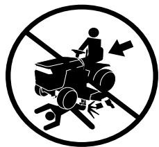
- Never carry passengers.
- Do not mow in reverse unless absolutely necessary. Always look down and behind before and while backing.
- Be aware of the mower discharge direction and do not point it at anyone. Do not operate the mower without either the entire grass catcher or the guard in place.
Slow down before turning. - Never leave a running machine unattended. Always turn off blades, set parking brake, stop engine, and remove keys before dismounting.
- Turn off blades when not mowing.
- Stop engine before removing grass catcher or unclogging chute.
Mow only in daylight or good artificial light. - Do not operate the machine while under the influence of alcohol or drugs.
- Watch for traffic when operating near or crossing roadways.
Use extra care when loading or unloading the machine into a trailer or truck. - Data indicates that operators, age 60 years and above, are involved in a large percentage of riding mower-related injuries. These operators should evaluate their ability to operate the riding mower safely enough to protect themselves and others from serious injury.
II. SLOPE OPERATION
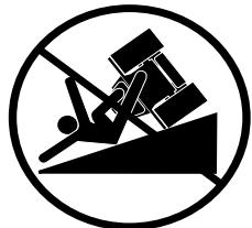
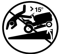
Slopes are a major factor related to loss-of-control and tipover accidents, which can result in severe injury or death. All slopes require extra caution. If you cannot back up the slope or if you feel uneasy on it, do not mow it.
DO:
Mow up and down slopes, not across.
- Remove obstacles such as rocks, tree limbs, etc.
- Watch for holes, ruts, or bumps. Uneven terrain could overturn the machine. Tall grass can hide obstacles.
- Use slow speed. Choose a low gear so that you will not have to stop or shift while on the slope.
- Follow the manufacturer's recommendations for wheel weights or counterweights to improve stability.
- Use extra care with grass catchers or other attachments. These can change the stability of the machine.
- Keep all movement on the slopes slow and gradual. Do not make sudden changes in speed or direction.
- Avoid starting or stopping on a slope. If tires lose traction, disengage the blades and proceed slowly straight down the slope.
DO NOT:
- Don't turn on slopes unless necessary, and then, turn slowly and gradually downhill, if possible.
- Do not mow near drop-offs, ditches, or embankments. The mower could suddenly turn over if a wheel is over the edge of a cliff or ditch, or if an edge caves in.
- Do not mow on wet grass. Reduced traction could cause sliding.
- Do not try to stabilize the machine by putting your foot on the ground.
- Do not use grass catcher on steep slopes.
III. CHILDREN
Tragic accidents can occur if the operator is not alert to the presence of children. Children are often attracted to the machine and the mowing activity. Never assume that children will remain where you last saw them.
- Keep children out of the mowing area and under the watchful care of another responsible adult.
- Be alert and turn machine off if children enter the area.
- Before and when backing, look behind and down for small children.
- Never carry children. They may fall off and be seriously injured or interfere with safe machine operation.
- Never allow children to operate the machine.
- Use extra care when approaching blind corners, shrubs, trees, or other objects that may obscure vision.
IV. SERVICE
-
Use extra care in handling gasoline and other fuels. They are flammable and vapors are explosive.
-
Use only an approved container.
- Never remove gas cap or add fuel with the engine running. Allow engine to cool before refueling. Do not smoke.
- Never refuel the machine indoors.
-
Never store the machine or fuel container inside where there is an open flame, such as a water heater.
-
Never run a machine inside a closed area.
-
Keep nuts and bolts, especially blade attachment bolts, tight and keep equipment in good condition.
- Never tamper with safety devices. Check their proper operation regularly.
- Keep machine free of grass, leaves, or other debris buildup. Clean oil or fuel spillage. Allow machine to cool before storing.
- Stop and inspect the equipment if you strike an object. Repair, if necessary, before restarting.
- Never make adjustments or repairs with the engine running.
- Grass catcher components are subject to wear, damage, and deterioration, which could expose moving parts or allow objects to be thrown. Frequently check components and replace with manufacturer's recommended parts, when necessary.
- Mower blades are sharp and can cut. Wrap the blade(s) or wear gloves, and use extra caution when servicing them.
- Check brake operation frequently. Adjust and service as required.
SAFETY RULES
Safe Operation Practices for Ride-On Mowers


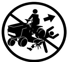
- Be sure the area is clear of other people before mowing. Stop machine if anyone enters the area.
- Never carry passengers or children even with the blades off.
- Do not mow in reverse unless absolutely necessary. Always look down and behind before and while backing.
- Never carry children. They may fall off and be seriously injured or interfere with safe machine operation.
- Keep children out of the mowing area and under the watchful care of another responsible adult.
- Be alert and turn machine off if children enter the area.
Before and when backing, look behind and down for small children.
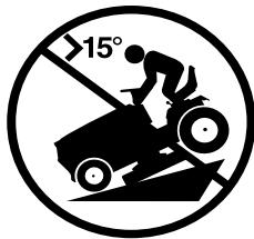
Mow up and down slopes (15irc Max), not across. - Remove obstacles such as rocks, tree limbs, etc.
- Watch for holes, ruts, or bumps. Uneven terrain could overturn the machine. Tall grass can hide obstacles.
- Use slow speed. Choose a low gear so that you will not have to stop or shift while on the slope.
- Avoid starting or stopping on a slope. If tires lose traction, disengage the blades and proceed slowly straight down the slope.
- If machine stops while going uphill, disengage blades, shift into reverse and back down slowly.
- Do not turn on slopes unless necessary, and then, turn slowly and gradually downhill, if possible.

Look for this symbol to point out important safety precautions. It means CAUTION!!! BECOME ALERT!!! YOUR SAFETY IS INVOLVED.

CAUTION: Do not coast down a hill in neutral, you may lose control of the tractor.

CAUTION: Tow only the attachments that are recommended by and comply with specifications of the manufacturer of your tractor. Use common sense when towing. Operate only at the lowest possible speed when on a slope. Too heavy of a load, while on a slope, is dangerous. Tires can lose traction with the ground and cause you to lose control of your tractor.

CAUTION: In order to prevent accidental starting when setting up, transporting, adjusting or making repairs, always disconnect spark plug wire and place wire where it cannot contact spark plug.
CONGRATULATIONS on your purchase of a Grass Catcher. It has been designed, engineered and manufactured to give you the best possible dependability and performance.
Should you experience any problems you cannot easily remedy, please contact your nearest authorized service center/department. They have competent, well trained technicians and the proper tools to service or repair this unit.
Please read and retain this manual. The instructions will enable you to assemble and maintain your Grass Catcher properly. Always observe the "SAFETY RULES".
TABLE OF CONTENTS
SAFETY RULES 2-3
BAG OF PARTS 4-5
ASSEMBLY 6
OPERATION 11
CUSTOMER RESPONSIBILITIES. 12
STORAGE 12
PREPARATION 13-14
REPAIR PARTS. Center of Manual
KNOW YOUR GRASS CATCHER
READ THIS OWNER'S MANUAL AND SAFETY RULES BEFORE ASSEMBLING OR OPERATING YOUR GRASS CATCHER. Compare the illustrations with the carton contents to familiarize yourself with the parts before starting the assembly. Study the operating instructions and safety precautions thoroughly to insure proper functioning of your Grass Catcher and to prevent injury to yourself and others. Save this manual for future reference.

The operation of any tractor can result in foreign objects thrown into the eyes, which can result in severe eye damage. Always wear safety glasses or eye shields before starting your tractor and while mowing. We recommend wide vision safety mask for over the spectacles or standard safety glasses.
UNPACKING INSTRUCTIONS
- Remove all parts and packing materials from carton.
- Fold flaps to inside of carton and turn carton upsidedown on floor of work area. To protect grass catcher cover during assembly place cover upsidedown on overturned carton.
- Check carton contents against list. Be sure all parts are there.
CARTON CONTENTS:
(2) Container Tops
(2) Container Bottoms
(1) Upper Chute
(1) Lower Chute
(1) Support Post
(1) Mounting Bracket
(1) Cover Assembly
(1) Cover Seal
(1) Bag of Parts
(1) Owner's Manual
NOTE: For ease of assembly, aside of your work area, lay out all hardware in the following groups. Each step of the assembly instructions will identify the group needed for that step.
| BAG OF PARTS CONTENTS | ||
| ASSEMBLY LOCATION | HARDWARE SHOWN ACTUAL SIZE | |
| MOWER DECK BAFFLE | GROUP "A" (1) Bolt 3/8-16 x 1-1/4 (1) Locknut 3/8-16 | |
| REAR MOUNTING BRACKET TO DRAW BAR | GROUP "B" (4) Shoulder Bolt - Self Tapping (4) Bolt 5/16 - 18 x 3/4 (4) Locknut 5/16-18 | |
| SUPPORT POST TO CONTAINER SUPPORT | GROUP "C" (3) Carriage Bolt 5/16-18 x 3/4 (3) Locknut 5/16-18 | |
| BAG OF PARTS CONTENTS (continued) | |
| SUPPORT POST TO MOUNTING BRACKET | GROUP "D" |
| (1) Bracket Support Pin | |
| (1) Retainer Spring | |
| (3) Tubing End Caps | |
| LOWER CHUTE ASSEMBLY TO MOWER DECK | GROUP "E" |
| (1) Washer 13/32 x 1 x 16 Ga. | |
| (1) Wing Nut | |
| CHUTE LATCH ASSEMBLY TO UPPER CHUTE | GROUP "F" |
| (1) Screw #10 x 1-1/8 | |
| (2) Washer 3/16 x 3/4 x 16 Ga. | |
| (1) Nut, Acorn #10 | |
| CHUTE LATCH ASSEMBLY TO LOWER CHUTE | GROUP "G" |
| (1) Rubber Latch | |
| (1) Screw #10 x 5/8 | |
| (1) Washer, Lock #10 | |
| (1) Washer 3/16 x 3/4 x 16 Ga. | |
ASSEMBLY
BEFORE YOU START TO ASSEMBLE THE GRASS CATCHER
Some tractor models may need minor modifications before you can mount the grass catcher to the tractor. Look carefully at the mower deck on your tractor and compare the deck mandrel to the illustrations below. If your mower deck mandrel looks like STYLE "A", your tractor is ready - proceed with the grass catcher assembly. If your mower deck mandrel looks like STYLE "B", go to the PREPARATION section in this manual.
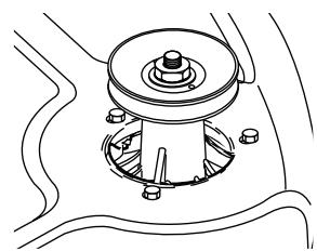
DECK MANDREL STYLE "A"
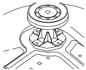
DECK MANDREL STYLE "B"
NOTE: When right hand (R.H.) and left hand (L.H.) are mentioned in this manual, it means when you are seated on the tractor, in the operator's position.
THESE ARE THE TOOLS YOU WILL NEED TO ASSEMBLE YOUR GRASS CATCHER:
(1) 3 / 8'' Wrench
(1) Drive Ratchet
(1) 1 / 2'' Wrench
(1) 3'' or longer Extension
(2) 9/16" Wrenches
(1) Short Handle
(1) 1 / 2 Socket
Phillips Screwdriver
(1) 9/16" Deep well Socket

CAUTION: BEFORE ASSEMBLING GRASS CATCHER TO TRACTOR:
- Depress clutch/brake pedal fully and set parking brake.
- Place gearshift/motion control lever in neutral (N) position.
- Place attachment clutch in "DISENGAGED" position.
- Turn ignition key "OFF" and remove key.
- Make sure the blade and all moving parts have completely stopped.
- Disconnect spark plug wire from spark plug and place wire where it cannot come in contact with plug.
1 MOWER DECK BAFFLE (See Fig. 1) Use Hardware - - GROUP "A"
- Raise your tractor mower deck to its highest position.
- Install the hex bolt, and locknut through mower deck baffle and tighten securely.
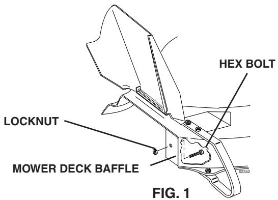
FIG. 1
2 REAR MOUNTING BRACKET (See Figs. 2A, 2B & 2C)
NOTE: If your tractor already has four (4) shoulder bolts installed on the rear drawbar, simply hang the mounting bracket, lanced tabs towards bottom, on the bolts. Discard hardware group "B" and disregard the remaining Step 2 instructions.
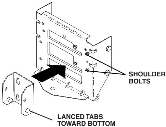
FIG. 2A
If your tractor does not have four (4) shoulder bolts installed on the drawbar, follow the instructions below.
Use Hardware - - GROUP "B"
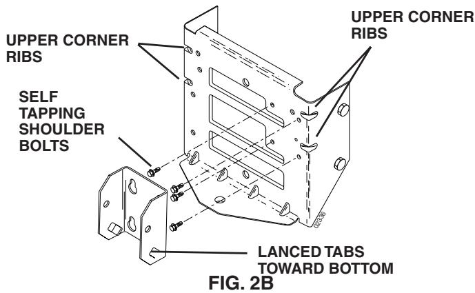
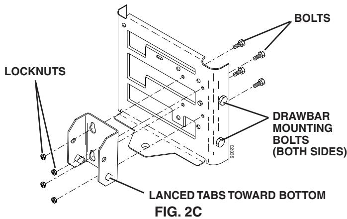
Only one set of hardware in GROUP "B" will be used to mount the rear mounting bracket. To determine which set is correct for your tractor, check to see if there are (2) two upper corner ribs on each side of drawbar. If your tractor has the upper corner ribs, use the (4) four self tapping shoulder bolts. If your tractor does not have the corner ribs, use the set of (4) four bolts and locknuts.
SELF TAPPING SHOULDER BOLTS (See Fig. 2B)
- Using the four formed holes in the drawbar, install the four shoulder bolts as shown and tighten securely.
- Hang the mounting bracket, lanced tabs towards bottom, on the bolts.
BOLTS AND LOCKNUTS (See Fig. 2C)
IMPORTANT: ON TRACTORS WITH FUEL TANK UNDER THE SEAT, THE DRAWBARMUST BE REMOVED FOR INSTALLATION OF MOUNTING BRACKET. TO REMOVE DRAWBAR, REMOVE TWO HEX BOLTS ON BOTH SIDES OF DRAWBAR.
- Assemble the mounting bracket, lanced tabs towards bottom, using the four smaller inside holes on the drawbar.
NOTE: If your tractor drawbar does not have the four correct holes for mounting the bracket, refer to the PREPARATION section of this manual.
- Install the four bolts and locknuts as shown and tighten securely.
- If drawbar was removed from tractor, reassemble to tractor at this time. Tighten securely.
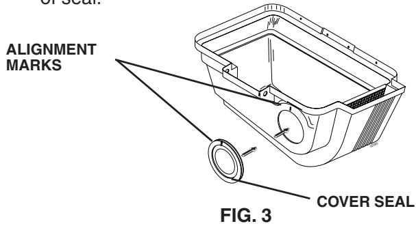
3 COVER SEAL (See Fig. 3) No hardware required
- Align mark on seal with mark at cover opening.
- Work seal into opening so cover sits between flanges of seal.
SUPPORT POST (See Fig. 4) Use Hardware -- GROUP "C"

4
CAUTION: Container support is spring loaded and locked to the cover. Handle cover assembly carefully so as not to unlatch the cover from the container support.
- Rotate cover assembly onto its side as shown.
- Assemble support post to container support with the three (3) carriage bolts and locknuts. Tighten securely.
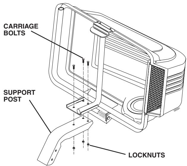
FIG. 4

MOUNTING TO TRACTOR (See Fig. 5) Use Hardware - - GROUP "D"
NOTE: For ease of assembly, you may wish to obtain the assistance of another person for mounting assembly to tractor.
- Raise seat on tractor to allow assembly to be mounted.
- With cover closed, lift assembly and place support post inside mounting bracket. Allow assembly to rest on lanced tabs of mounting bracket.
- Line up holes in mounting bracket with holes in support post and insert bracket support pin. Secure with retainer spring.
- Unlatch and open cover.
- Install the three (3) tubing end caps onto container support.
- Tap each end cap onto container support tubes to seat securely.
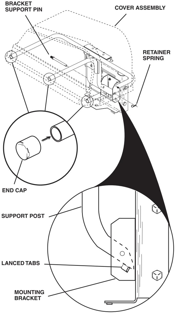
FIG. 5
6 CONTAINER ASSEMBLY (See Fig. 6) No hardware required
- Place bottom half inside of top half, as shown.
- Place one foot inside bottom half and lift top half to meet bottom half.
- Press halves tightly together while lifting top to lock into place as shown.
IMPORTANT:BEFORE LOCKING THE TABS, HOOKED EDGES ON BOTH HALVES MUST OVERLAP TO FORM SEAL AS SHOWN IN INSERT.
4. Repeat for second container.
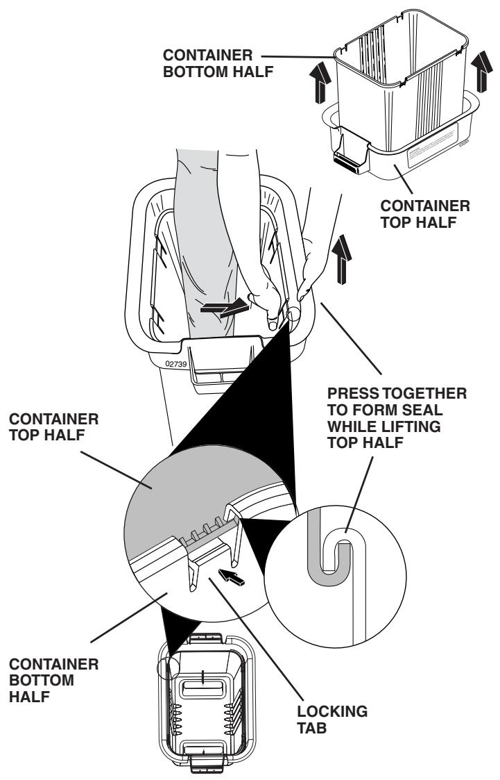
FIG. 6
ASSEMBLY CHECK: Squeeze sides of lower half of container and check that there is no gap between upper and lower halves. If a gap appears, unlock tabs to separate container halves and repeat instructions above.

7 CONTAINER MOUNTING (See Fig. 7)
No hardware required
- Install one container to left side first with warning to outside of unit. Install other container to right side.
NOTE: Right container should always overlap left container at center support. - Close cover and lock latch handle over center support tube.
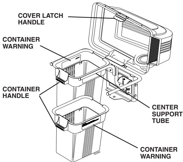
FIG. 7
8 LOWER CHUTE (See Fig. 8) Use Hardware - - GROUP "E"
- Raise and hold deflector shield in upright position.
- Slide back edge of chute over rear corner of mower deck and pivot forward.
- Align slot in lower chute with hex bolt in mower deck baffle and close chute over deck opening.
- Secure with washer and wing nut.

CAUTION: Do not remove discharge guard from mower. Raise and hold guard when attaching lower chute and allow it to rest on chute while in operation.
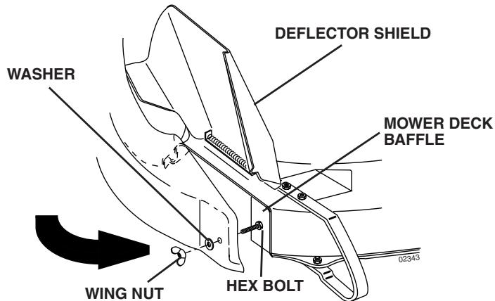
FIG. 8
9 CHUTE LATCH ASSEMBLY (See Fig. 9)
Use Hardware - - GROUPS "F & G"
- Assemble latch pin to upper chute, as shown.
- Press weld nut into rubber latch and assemble rubber latch to lower chute, as shown.
- Tighten all hardware securely.
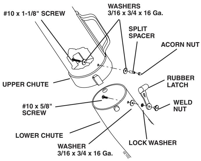
FIG. 9
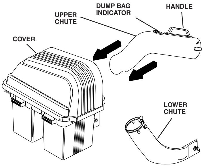
FIG. 10A
10 UPPER CHUTE (See Figs. 10A & 10B) No hardware required
- Lower mower deck to its lowest cutting position.
- Assemble upper chute by inserting curved end into hole in back of cover.
NOTE: Handle carefully so as not to damage dump bag indicator.
- Push in and turn upper chute until it is in line with lower chute.
- Align the bosses on lower chute with alignment slots on upper chute and slide together.
- Secure with rubber latch by hooking hole in latch over latch pin.
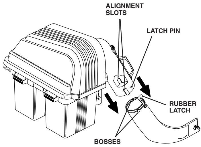
FIG. 10B
11 LEVEL MOWER DECK No hardware required
Be sure deck is properly leveled for best mower performance.
See your tractors owner's manual for instructions.
TIPS FOR IMPROVED BAGGING OPERATION:
Follow the mower operation instructions in your tractor owner's manual.
When operating your grass catcher on a lawn where grass and leaf bagging equipment has not been used, you are picking up thatch and debris that has accumulated for long periods of time. The amount collected and the total time of operation may be greater than you will experience with regular use of your grass catcher.
Always run throttle at full speed when bagging.
- Select a gear low enough to give good mower cutting performance, good quality cut and good bagging performance.
NOTE: It may be necessary to overlap width of cut to suit your conditions.
- If grass is extremely tall, it should be mowed twice. The first time relatively high, the second time to desired height.
Use left hand side of mower for trimming. - Plastic trash bags can be inserted inside grass catcher containers for ease of debris disposal. To remove the plastic trash bags when full:
a. Disengage blades, shift into neutral, engage the parking brake and stop the engine.
b. Raise seat. Unlatch and raise cover.
c. Remove one container at a time by grasping container handles and pulling toward the rear, off of the tube rails.
d. With the container resting on the ground, close and secure the top of the plastic lawn bag.
e. Tip the container on its side and slide the filled bag from the container.
f. Install a new plastic lawn bag with the edges of the bag draped over upper lip of the container.
g. Repeat for other containers.
h. Reinstall containers making sure right container overlaps left container at center supports.
j. Close cover and secure latches over center support tubes.
- Avoid cutting wet grass or in the morning while the dew is still heavy. Grass clippings collected under these conditions tend to be sticky and adhere to the walls of the flow path causing clogging.
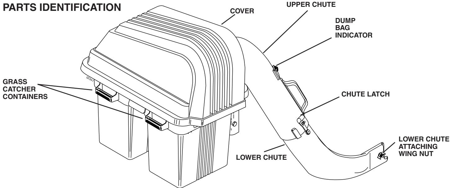
- Your dagger is equipped with a dump bag indicator. As the bags become full, the flow indicating ball will drop down in its slot, indicating that the bags are full or the chutes have become clogged. Care should be taken not to damage the parts and that the ball moves freely at the beginning of each use.
NOTE: To help prevent clogging of chutes, check/empty bags when ball begins to drop down in the slot. Experience will teach you the best time to empty the bags.
- If the grass catcher fails to pick up cut grass or leaves, it is an indication that clogging has occurred in the system or that the grass catcher containers are full.
a. Disengage blades, shift into neutral, engage the parking brake and stop the engine.
- Raise seat. Unlatch and raise cover.
- Slide out containers and dispose of clippings .
- Replace containers, close cover, and latch.
b. Unlatch chutes and check for clogging
- Remove all debris in chutes.
- Reassemble and latch chutes
c. Check to insure dump bag indicator has not become clogged.
- The air passage hole must be clear of debris. Gently insert a small twig or wire into passageway to clear.

CAUTION
- Do not operate mower with grass catcher partially installed.
- Disengage blades and stop engine before leaving tractor seat to empty containers, unclogging chutes, etc.
- Close cover before starting.
- Disengage mower when crossing driveways or gravel surfaces and other areas where thrown objects could be a hazard.
- Do not attempt to vacuum up cans or other potentially hazardous projectiles.
CUSTOMER RESPONSIBILITIES
GENERAL RECOMMENDATIONS
Always observe safety rules when performing any maintenance.
Before each use check for loose fasteners.
- Clean unit thoroughly after each use.
BLADE CARE
For best results mower blades must be kept sharp. Replace bent or damaged blades.
- See BLADE CARE instructions in your tractor owner's manual.

CAUTION: BEFORE PERFORMING ANY MAINTENANCE, SERVICE OR ADJUSTMENTS:
- Depress clutch brake pedal fully and set parking brake.
- Place gearshift/motion control lever in "NEUTRAL" position.
- Place clutch control in "DISENGAGED" position.
- Turn ignition key to "OFF" position.
Make sure blades and all moving parts have completely stopped. - Disconnect spark plug wire(s) from spark plug(s) and place wire where it cannot come in contact with plug.

CAUTION: Grass catcher components are subject to wear, damage and deterioration, which could expose moving parts or allow objects to be thrown. Frequently check components and replace with manufacturer's recommended parts, when necessary.
STORAGE
When grass catcher is to be stored for a period of time, clean it thoroughly, remove all dirt, grass, leaves, etc. Store in a clean, dry place.

CAUTION: Do not leave grass in bagger containers. Empty containers after each use and before storing. Failure to do so may result in spontaneous combustion which could develop into a fire.
CAUTION: BEFORE PROCEEDING WITH PREPARATION OF TRACTOR:
- Depress clutch/brake pedal fully and set parking brake.
- Place gearshift/motion control lever in neutral (N) position.
- Place attachment clutch in "DISENGAGED" position.
- Turn ignition key "OFF" and remove key.
- Make sure the blade and all moving parts have completely stopped.
- Disconnect spark plug wire from spark plug and place wire where it cannot come in contact with plug.

NOTE
ON SOME MODEL TRACTORS, MINOR MODIFICATIONS MAY BE NECESSARY TO MOUNT YOUR NEW GRASS CATCHER. NOT ALL MODEL TRACTORS WILL NEED THE FOLLOWING MODIFICATIONS. CHECK EACH STEP CAREFULLY TO DETERMINE IF MODIFICATION IS REQUIRED. ONCE YOUR MODEL TRACTOR CONFORMS TO THIS SECTION PROCEED TO ASSEMBLY.
To Prepare your Grass Catcher you may need:
(1) Heavy Shears
(1) 11 / 32 Drill Bit
or
(1) 13 / 32'' Drill Bit
(1) Hand Saw
(2) 7/16" Wrench
(1) Ruler
(2) 1 / 2'' Wrench
(1) Drill Motor
(1) 9/16" Wrench
(1) 9 / 32'' Drill Bit
A socket wrench set will make assembly easier. Standard wrench sizes are listed.
1 TRIM DEFLECTOR SHIELD (See Fig. 11)
On some model tractors, it may be necessary to trim the bottom corner of the deflector shield. If your deflector shield is not trimmed, use heavy shears or a hand saw to cut off corner as shown.
NOTE: To assist in proper cut off, there is a template in the back of this manual that may be used.
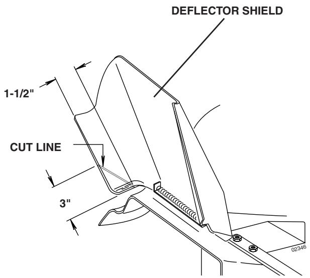
FIG. 11
2 DRILL HOLE IN DECK BAFFLE (See Fig. 12)
On some model tractors, it may be necessary to drill a hole in the mower deck baffle. If your mower deck baffle does not have a hole drill a 13/32th hole as shown.
NOTE: To assist in proper hole location, there is a template in the back of this manual that may be used.
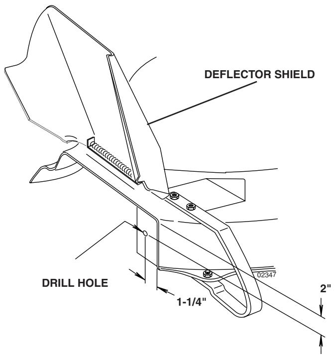
FIG. 12
3 DRILL 4 HOLE BOLT PATTERN (See Figs. 13,14 & 15)
On some model tractors, it may be necessary to drill new holes in drawbar for the mounting bracket. To determine if you need to drill holes in your drawbar, closely look at the illustration below.
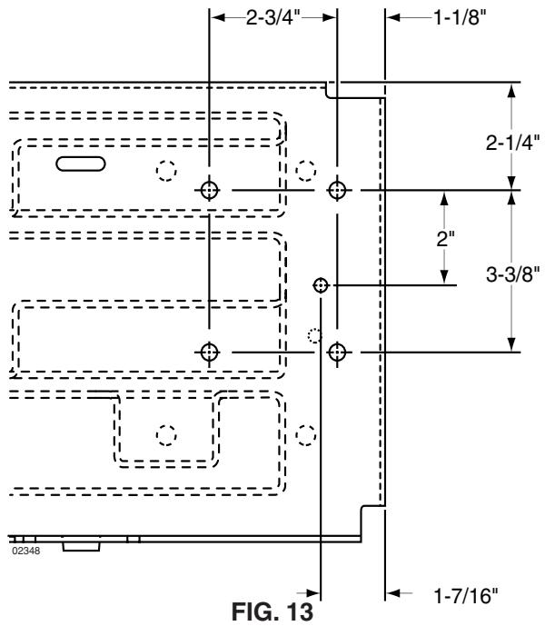
Your drawbar may or may not have some or all of the holes shown. For the assembly of your new grass catcher only the five holes dimensioned will be used. If your drawbar does not have the five holes in the correct positions continue with this section.
- Remove the drawbar by removing the two mounting bolts on each side. Keep hardware for remounting.
NOTE: If your tractor has a wire loop mounted to the drawbar, remove it at this time.
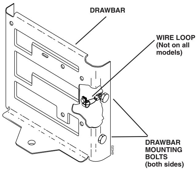
FIG. 14
- Place the drawbar in a vice or similar locking device.
- Cut out the 4 hole bolt pattern template from the back of this manual.
- Align top and right edge of template and drawbar.
- Tape in position.
- Mark and drill hole #1 only, using a 11/32" drill bit.
- Assemble mounting bracket to drilled hole in drawbar with one hex bolt and nut from hardware group "B".
NOTE: Mounting bracket must be assembled with lanced tabs to bottom as shown.
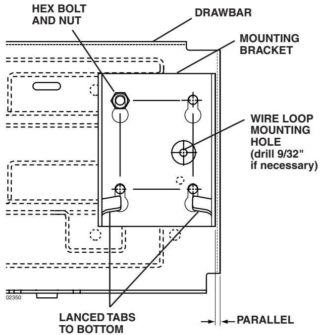
FIG. 15
- Align bracket so it is parallel with right edge of drawbar and tighten securely. Holes in bracket should line up with remaining holes in template.
- Using bracket as a template, drill remaining three (3) 11 / 32'' mounting holes.
NOTE: If your tractor is equipped with a wire loop, drill new mounting hole as shown, if necessary.
- For ease of assembly mounting bracket should be assembled at this time (refer to "REAR MOUNTING BRACKET" in ASSEMBLY section of this manual).
- Remount drawbar to tractor using hardware previously removed.
NOTE: Failure to reconnect the wire loop connection will result in not being able to start tractor.
PROCEED WITH ASSEMBLY INSTRUCTIONS IN THE FRONT OF THIS MANUAL
DEFLECTORTRIMTEMPLATE
MOWER DECK BAFFLE DRILL TEMPLATE
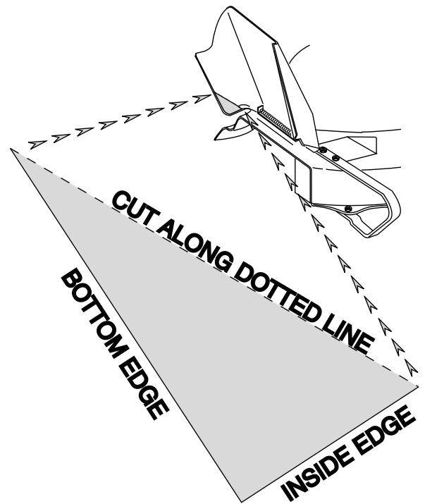
USETRIANGLE ABOVE FOR A GUIDETOTRIMMING YOUR DEFLECTOR SHIELD. CUT OUT SHADED AREA AND PLACE ON INSIDE BOTTOM EDGE OF DEFLECTOR. TRIM DEFLECTOR ALONG DOTTED LINE USING EITHER HEAVY SHEARS OR A HAND SAW.
TOP EDGE
RIGHT
EDGE
USE TEMPLATE ABOVE FOR A GUIDE TO DRILLING YOUR MOWER DECK BAFFLE.CUT OUT SHADED AREA AND ALIGN WITH TOP, AND RIGHT, EDGE OF BAFFLE. DRILL A 13/32" HOLE AT SPECIFIED LOCATION.
NOTES

NOTES
NOTES
REPAIR PARTS/PIÉCES DE RECHANGE
GRASS CATCHER - MODEL NUMBER C38D / RAMASSE-HERBE - - NUMÉRO DE MODELE C38D
PRODUCT NUMBER 954 14 00-50 / NUMÉRO DE PRODUIT 954 14 00-50
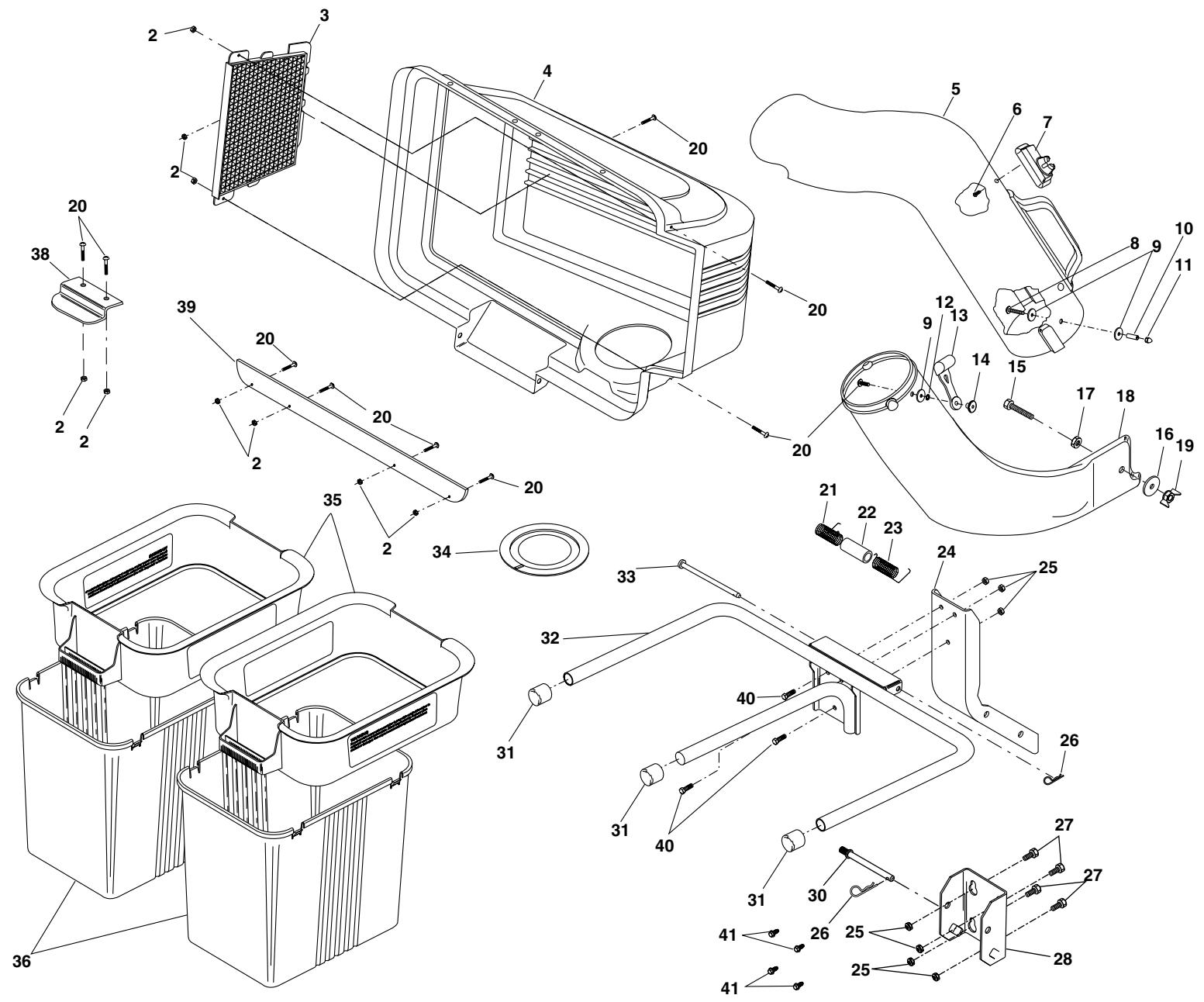
REPAIR PARTS/PIÉCES DE RECHANGE
GRASS CATCHER - MODEL NUMBER C38D / RAMASSE-HERBE - - NUMÉRO DE MODELE C38D
PRODUCT NUMBER 954 14 00-50 / NUMÉRO DE PRODUIT 954 14 00-50
| KEY NO. | PART NO. | DESCRIPTION | DESCRIPTION | KEY NO. | PART NO. | DESCRIPTION | DESCRIPTION |
| 2 | 532069180 | Nut, Crownlock #10-24 | Écrou auto-serrant #10-24 | 22 | 532133235 | Spacer, Cover | Entretoise de couvercle |
| 3 | 532127533 | Screen, Cover | Grillage de couvercle | 23 | 532132983 | Spring, Cover R.H. (gray) | Ressort de couvercle C.D. |
| 4 | 532171061 | Cover Asm.(Incl. 3,38,39) | Couvercle Ens. | 24 | 532126813 | Post, Support | Poteau de soutien |
| (Y combris 3,38,39) | 25 | 873800500 | Locknut 5/16 x 18 | Écrou frein 5/16 x 18 | |||
| 5 | 532139569 | Chute, Upper | Glissière supérieure | 26 | 532124670 | Spring, Retainer | Ressort de retenue |
| 6 | 818021008 | Screw, Special | Vis spéciale | 27 | 874760512 | Bolt, Hex 5/16-18 x 3/4 | Boulon H 5/16 -18 x 3/4 |
| 7 | 532140572 | Dump Bag Indicator | Indicateur de sac de déchéignment | 28 | 532170053 | Bracket, Mounting | Support de montage |
| 30 | 532131137 | Pin, Support Post | Goupille du poteau de soutien | ||||
| 8 | 532087175 | Screw, #10-24 x 1-1/8 | Vis #10-24 x 1-1/8 | 31 | 532174083 | Plug, Tubing End | Chapeau de l'extrémité de tuyau |
| 9 | 819061216 | Washer 3/16x3/4x16 Ga. | Rondelle 3/16x3/4x16 Ja. | ||||
| 10 | 532007206 | Spacer, Split | Entretoise fendue | 32 | 532126919 | Bagger, Frame | Cadre de ramasse-herbe |
| 11 | 532060867 | Nut, Acorn #10-24 | Écrou borgne #10-24 | 33 | 532128600 | Pin, Hinge | Goupille de charnière |
| 12 | 810071000 | Washer, lock | Rondelle frein | 34 | 532127534 | Gasket, Cover | Garniture de couvercle |
| 13 | 532109808 | Latch, Chute | Loquet de glissière | 35 | 532183286 | Container, Top | Conteneur supérieur |
| 14 | 532125004 | Nut, Weld | Axe du loquet | 36 | 532129586 | Container, Bottom | Conteneur inférieur |
| 15 | 874930620 | Bolt, Hex 3/8-16 x 1-1/4 | Boulon H 3/8-16 x 1-1/4 | 38 | 532130895 | Latch Handle, Cover | Poingnée de loquet de couvercle |
| 16 | 819131616 | Washer 13/32x1x16 Ga. | Rondelle 13/32x1x16 Ja. | ||||
| 17 | 873930600 | Locknut 3/8-16 | Écrou frein 3/8-16 | 39 | 532155042 | Strip, Reinforcement | Bande |
| 18 | 532131970 | Chute, Lower | Glissière inférieure | 40 | 872110506 | Carriage Bolt 5/16-18 x 3/4 | Boulon de chariot |
| 19 | 532135651 | Wingnut 3/8-16 | Écrou à oreilles 3/8-16 | 41 | 532170165 | Shoulder Bolt | Boulon |
| 20 | 871081010 | Screw #10-24 x 5/8 | Vis #10-24 x 5/8 | Hex, Self Tapping | 5/16-18 x 1/2 | ||
| 21 | 532132796 | Spring, Cover L.H. (black) | Ressort de couvercle C.G. | — | 532140603 | Owner's Manual | Manuel du proriétaire |
- GENERAL OPERATION
- SLOPE OPERATION
- DO:
- DO NOT:
- CHILDREN
- SERVICE
- SAFETY RULES
- Safe Operation Practices for Ride-On Mowers
- TABLE OF CONTENTS
- KNOW YOUR GRASS CATCHER
- UNPACKING INSTRUCTIONS
- CARTON CONTENTS:
- ASSEMBLY
- BEFORE YOU START TO ASSEMBLE THE GRASS CATCHER
- THESE ARE THE TOOLS YOU WILL NEED TO ASSEMBLE YOUR GRASS CATCHER:
- CAUTION: BEFORE ASSEMBLING GRASS CATCHER TO TRACTOR:
- MOWER DECK BAFFLE (See Fig. 1) Use Hardware - - GROUP "A"
- REAR MOUNTING BRACKET (See Figs. 2A, 2B & 2C)
- Use Hardware - - GROUP "B"
- SELF TAPPING SHOULDER BOLTS (See Fig. 2B)
- BOLTS AND LOCKNUTS (See Fig. 2C)
- COVER SEAL (See Fig. 3) No hardware required
- SUPPORT POST (See Fig. 4) Use Hardware -- GROUP "C"
- MOUNTING TO TRACTOR (See Fig. 5) Use Hardware - - GROUP "D"
- CONTAINER ASSEMBLY (See Fig. 6) No hardware required
- CONTAINER MOUNTING (See Fig. 7)
- No hardware required
- LOWER CHUTE (See Fig. 8) Use Hardware - - GROUP "E"
- CHUTE LATCH ASSEMBLY (See Fig. 9)
- Use Hardware - - GROUPS "F & G"
- UPPER CHUTE (See Figs. 10A & 10B) No hardware required
- LEVEL MOWER DECK No hardware required
- TIPS FOR IMPROVED BAGGING OPERATION:
- CAUTION
- CUSTOMER RESPONSIBILITIES
- GENERAL RECOMMENDATIONS
- BLADE CARE
- CAUTION: BEFORE PERFORMING ANY MAINTENANCE, SERVICE OR ADJUSTMENTS:
- STORAGE
- CAUTION: BEFORE PROCEEDING WITH PREPARATION OF TRACTOR:
- NOTE
- TRIM DEFLECTOR SHIELD (See Fig. 11)
- DRILL HOLE IN DECK BAFFLE (See Fig. 12)
- DRILL 4 HOLE BOLT PATTERN (See Figs. 13,14 & 15)
- PROCEED WITH ASSEMBLY INSTRUCTIONS IN THE FRONT OF THIS MANUAL
- NOTES
- REPAIR PARTS/PIÉCES DE RECHANGE
- GRASS CATCHER - MODEL NUMBER C38D / RAMASSE-HERBE - - NUMÉRO DE MODELE C38D
- PRODUCT NUMBER 954 14 00-50 / NUMÉRO DE PRODUIT 954 14 00-50
Brand : POULAN
Model : C38D
Category : Brush cutter