
TOWER 20 AM - Outdoor motion detector VISONIC - Free user manual and instructions
Find the device manual for free TOWER 20 AM VISONIC in PDF.
| Product Type | Outdoor motion detector |
| Brand | VISONIC |
| Model | TOWER 20 AM |
| Dimensions (H x W x D) | 157 x 147 x 124 mm |
| Weight | 600 g |
| Power Supply | 8-16 VDC |
| Standby Consumption | 15 mA @ 12 VDC |
| Alarm Consumption | 70 mA max |
| Detection Range | 12 m (40 ft) / 90° |
| Detection Technology | 8 independent quad PIR detectors (Octa-QUAD™) with TMR processing |
| Pet Immunity | Up to 18 kg (40 lb) |
| Anti-Masking Protection | Yes, intelligent detection (differentiates spray from rain) |
| Tamper Protection | Yes, against opening and wall removal |
| Protection Rating | IP55, environmental class IV |
| Operating Temperature | -35°C to +60°C |
| Maximum Humidity | 95% |
| White Light Immunity | >25,000 lux |
| Alarm Output | NC solid-state relay, 100 mA / 30 V |
| Fault Output | NC solid-state relay, 100 mA / 30 V |
| Tamper Output | NC contact, 50 mA / 30 V |
| Mounting Height | 1.5 to 3.0 m |
| Vertical Adjustment | 0° to -10° in 2.5° steps |
| Horizontal Adjustment | -45° to +45° in 5° steps |
| Remote LED Test Input (TST) | Yes, activates LEDs if internal switch is OFF |
| Standards | FCC Part 15, EN 50130-4, EN 60950, EN 50130-5 |
Frequently Asked Questions - TOWER 20 AM VISONIC
User questions about TOWER 20 AM VISONIC
0 question about this device. Answer the ones you know or ask your own.
Ask a new question about this device
Download the instructions for your Outdoor motion detector in PDF format for free! Find your manual TOWER 20 AM - VISONIC and take your electronic device back in hand. On this page are published all the documents necessary for the use of your device. TOWER 20 AM by VISONIC.
USER MANUAL TOWER 20 AM VISONIC
Outdoor Octa-Quad™ Mirror Detector with Anti-Mask [Grade 3]
1. INTRODUCTION
Detector's Features
- Patented 8 independent quad PIR detectors (Octa-QUAD™) operating in true Quad configuration with true motion recognition (TMR) processing for each of the 8 PIR detectors and central motion processing - can distinguish between a moving intruder and moving trees and bushes.
- Advance Obsidian Black Mirror™ optics (patent pending).
- High protection against snow, rain, dust, wind and direct sunlight.
- Tamper protection against opening and removal from wall.
-
Alarm LED is visible in sunlight.
-
Low voltage detection
Self test
Day & night or night only setting. - Robust housing with recessed window.
- Smart anti masking can distinguish between masking spray and rain.
- Immunity to pets weighing up to 18Kg (40lb), not pet alley.
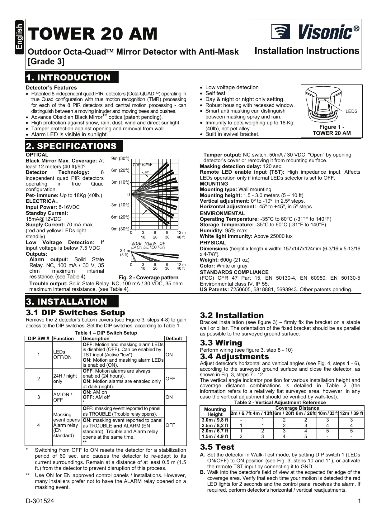
Built in swivel bracket.
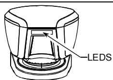
Figure 1 - TOWER 20 AM
2. SPECIFICATIONS
OPTICAL
Black Mirror Max. Coverage: At least 12 meters (40 ft)/90°.
Detector Technology: 8 independent quad PIR detectors operating in true Quad configuration.
Pet-immune:Up to 18Kg (40lb.)
ELECTRICAL
Input Power: 8-16VDC
Standby Current:
15mA@12VDC.
Supply Current: 70mA max.
(red and yellow LEDs light steadily)
Low Voltage Detection: If input voltage is below 7.5 VDC Outputs:
Alarm output: Solid State Relay. NC, 100 mA / 30 V, 35 ohm maximum internal resistance. (see Table 4).
Trouble output: Solid State Relay. NC, 100 mA / 30 VDC, 35 ohm maximum internal resistance. (see Table 4).
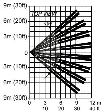
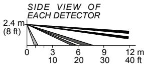
Fig. 2 - Coverage pattern
C, 100 mA / 30 VDC, 35 ohm (Table 4).
Tamper output: NC switch, 50mA / 30 VDC. "Open" by opening detector's cover or removing it from mounting surface.
Masking detection delay: 120 sec.
Remote LED enable input (TST): High impedance input. Affects LEDs operation only if internal LEDs selector is set to OFF.
MOUNTING
Mounting type: Wall mounting
Mounting height: 1.5 - 3.0 meters (5 - 10 ft)
Vertical adjustment: 0^ to -10^ , in 2.5^ steps.
Horizontal adjustment: -45^ to +45^ , in 5^ steps.
ENVIRONMENTAL
Operating Temperature: -35^ to 60^ (-31°F to 140°F)
Storage Temperature: -35^ to 60^ (-31°F to 140°F)
Humidity: 95% max.
White light immunity: Above 25000 lux
PHYSICAL
Dimensions (height x length x width: 157x147x124mm (6-3/16 x 5-13/16 x 4-7/8").
Weight: 600g (21 oz)
Color: White or gray
STANDARDS COMPLIANCE
(FCC) CFR 47 Part 15, EN 50130-4, EN 60950, EN 50130-5
Environmental class IV. IP 55.
US Patents: 7250605, 6818881, 5693943. Other patents pending.
3. INSTALLATION
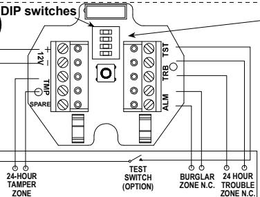
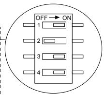
3.1 DIP Switches Setup
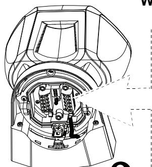
Remove the 2 detector's bottom covers (see Figure 3, steps 4-8) to gain access to the DIP switches. Set the DIP switches, according to Table 1:
Table 1 - DIP Switch Setup
| DIP SW # | Function | Description | Default |
| 1 | LEDs OFF/ON | OFF: Motion and masking alarm LEDs is disabled (OFF). Can be enabled by TST input (Active "low") ON: Motion and masking alarm LEDs is enabled (ON). | ON |
| 2 | 24H / night only | OFF: Motion alarms are always enabled (24 hours). ON: Motion alarms are enabled only at dark (night). | OFF |
| 3 | AM ON / OFF | ON: AM on OFF: AM off * | ON |
| 4 | Masking event opens Alarm relay (EN standard) | OFF: masking event reported to panel as TROUBLE (Trouble relay opens). ON: masking event reported to panel as TROUBLE and ALARM (EN standard). Trouble and Alarm relay opens at the same time. | OFF |
- Switching from OFF to ON resets the detector for a stabilization period of 60 sec. and causes the detector to re-adapt to its current surroundings. Remain at a distance of at least 0.5m (1.5 ft.) from the detector to prevent disruption of this process.
** Use ON for EN approved control panels / installations. However, many installers prefer not to have the ALARM relay opened on a masking event.
3.2 Installation
Bracket installation (see figure 3) – firmly fix the bracket on a stable wall or pillar. The orientation of the fixed bracket should be as parallel as possible to the surveyed ground surface.
3.3 Wiring
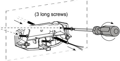
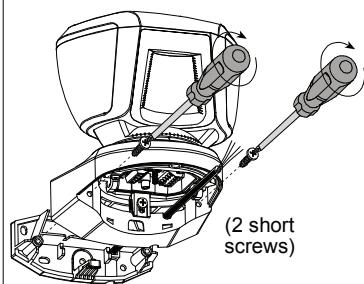
Perform wiring (see figure 3, step 8 - 10)
3.4 Adjustments
Adjust detector's horizontal and vertical angles (see Fig. 4, steps 1 - 6), according to the surveyed ground surface and close the detector, as shown in Fig. 3, steps 7 - 12. The vertical angle indicator position for various installation height and coverage distance combinations is detailed in Table 2 (the information refers to a relatively flat surveyed area. however, in any case the vertical adjustment should be verified by walk-test).
Table 2 - Vertical Adjustment Reference
| Mounting Height | Coverage Distance | |||||
| 2m / 6.7ft | 4m / 13ft | 6m / 20ft | 8m / 26ft | 10m / 33ft | 12m / 39 ft | |
| 3.0m / 9,8 ft | - | 1 | 2 | 2 | 3 | 3 |
| 2.5m / 8,2 ft | 1 | 1 | 2 | 3 | 4 | 4 |
| 2.0m / 6.7 ft | 1 | 2 | 3 | 4 | 5 | 5 |
| 1.5m / 4.9 ft | 2 | 3 | 4 | 5 | - | - |
3.5 Test
A. Set the detector in Walk-Test mode, by setting DIP switch 1 (LEDs ON/OFF) to ON position (see Fig. 3, steps 10 and 11), or activate the remote TST input by connecting it to GND.
B. Walk into the detector's field of view at the expected far edge of the coverage area. Verify that each time your motion is detected the red LED lights for 2 seconds and the control panel receives the alarm. If required, perform detector's horizontal / vertical readjustments.
Important! Instruct the user to perform walk test at least once a week, to verify proper operation of the detector.
C. Place a piece of cardboard on the detector's front side, to deliberately mask the optical window. After 2 minutes, the yellow LED should light (see Table 3) and the alarm control panel should receive the masking alarm.
D. Remove the masking from the detector's front side. The LED should extinguish (after about 30 seconds).
Table 3 - LED Operation
| Event / status | Indication |
| Low voltage | Red flashing |
| Warm-up (60sec.) | Yellow + Red flashing alternately |
| Self-test failure | Yellow + Red flashing simultaneously |
| AM detection | Yellow ON |
| ALARM | Red ON for 2 sec. |
Table 4 - Relay Outputs
| Event / status | Relay Output | |
| Trouble | Alarm | |
| Complete power failure | Open | Open |
| Standby | Closed | Closed |
| Low voltage | Open | Closed |
| Self-test failure | Open | Closed |
| AM detection DIP-SW4 = ON | Open | Open |
| AM detection DIP-SW4 = OFF | Open | Closed |
| Alarm | Closed | Open for 2 sec. |
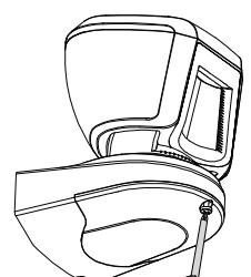
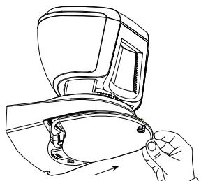
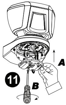
3.6 Cover Closure (see Fig. 4, steps 7 - 10)
1
2
3
Press firmly to release the bracket
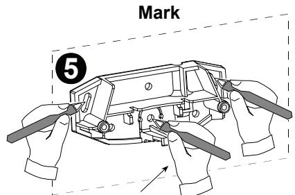
6
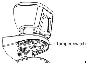
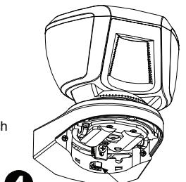
For wall Tamper switch
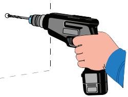
Drill
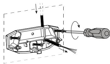
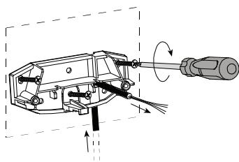
7 Bracket fastening (3 cable routing options)
Note
The 2 screw holes enable adjustment of the bracket on the wall, if needed as a result of the walk test.
Fasten
8
9
Wiring
10
ALARM CONTROL PANEL
Figure 3 - Installation
Mounting on bracket
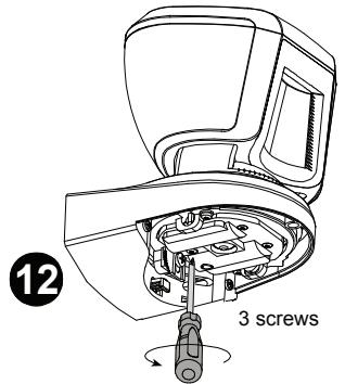
Figure 3 - Installation (Continued)
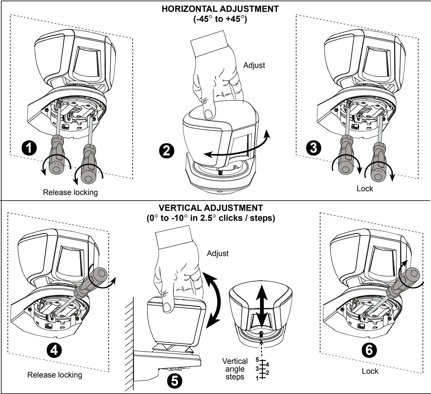
Figure 4 - Adjustment and Cover Closure
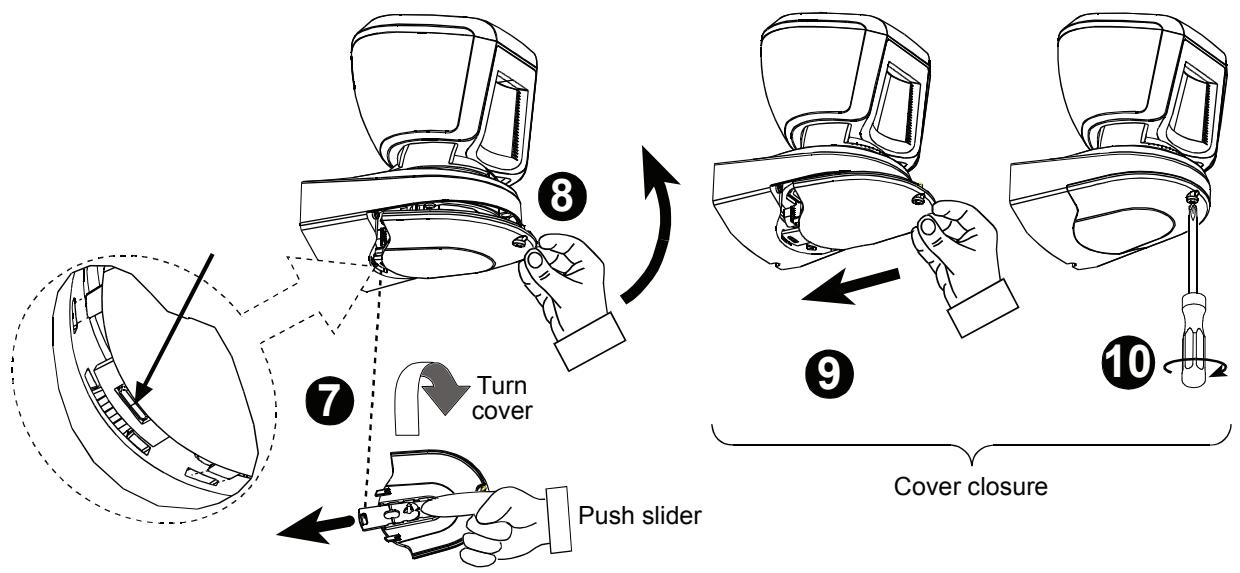
COVER CLOSURE
Figure 4 - Adjustment and Cover Closure (Continued)
4. MISCELLANEOUS COMMENTS
This equipment has been tested and found to comply with the limits for a Class B digital device, pursuant to Part 15 of the FCC Rules. These limits are designed to provide reasonable protection against harmful interference in a residential installation. This equipment generates, uses and can radiate radio frequency energy and, if not installed and used in accordance with the instructions, may cause harmful interference to radio communications. However, there is no guarantee that interference will not occur in a particular installation. If this equipment does cause harmful interference to radio or television reception, which can be determined by turning the equipment off and on, the user is encouraged to try to correct the interference by one or more of the following measures:
- Reorient or relocate the receiving antenna.
- Increase the separation between the equipment and receiver.
- Connect the equipment to an outlet on a circuit different from that to which the receiver is connected.
- Consult the dealer or an experienced radio/TV technician.
FCC Warning! Modifications not expressly approved by Visonic Ltd. could void the user authority to operate the equipment under FCC rules.
WARRANTY
Visonic Limited (the "Manufacturer") warrants this product only (the "Product") to the original purchaser only (the "Purchaser") against defective workmanship and materials under normal use of the Product for a period of twelve (12) months from the date of shipment by the Manufacturer.
This Warranty is absolutely conditional upon the Product having been properly installed, maintained and operated under conditions of normal use in accordance with the Manufacturers recommended installation and operation instructions. Products which have become defective for any other reason, according to the Manufacturers discretion, such as improper installation, failure to follow recommended installation and operational instructions, neglect, willful damage, misuse or vandalism, accidental damage, alteration or tampering, or repair by anyone other than the manufacturer, are not covered by this Warranty.
The Manufacturer does not represent that this Product may not be compromised and/or circumvented or that the Product will prevent any death and/or personal injury and/or damage to property resulting from burglary, robbery, fire or otherwise, or that the Product will in all cases provide adequate warning or protection. The Product, properly installed and maintained, only reduces the risk of such events without warning and it is not a guarantee or insurance that such events will not occur.
THIS WARRANTY IS EXCLUSIVE AND EXPRESSLY IN LIEU OF ALL OTHER WARRANTYES, OBLIGATIONS OR LIABILITIES, WHETHER WRITTEN, ORAL, EXPRESS OR IMPLIED, INCLUDING ANY WARRANTY OF MERCHANTABILITY OR FITNESS FOR A PARTICULAR PURPOSE, OR OTHERWISE. IN NO CASE SHALL THE MANUFACTURER BE LIABLE TO ANYONE FOR ANY CONSEQUENTIAL OR INCIDENTIAL DAMAGES FOR BREACH OF THIS WARRANTY OR ANY OTHER WARRANTYES WHATSOEVER, AS AFORESAID.
THE MANUFACTURER SHALL IN NO EVENT BE LIABLE FOR ANY SPECIAL, INDIRECT, INCIDENTAL, CONSEQUENTIAL OR PUNITIVE DAMAGES OR FOR LOSS, DAMAGE, OR EXPENSE, INCLUDING LOSS OF USE, PROFITS, REVENUE, OR GOODWILL, DIRECTLY OR INDIRECTLY ASRISING FROM PURCHASER'S USE OR INABILITY TO USE THE PRODUCT, OR FOR LOSS OR DESTRUCTION OF OTHER PROPERTY OR FROM ANY OTHER CAUSE, EVEN IF MANUFACTURER HAS BEEN ADVISED OF THE POSSIBILITY OF SUCH DAMAGE.
THE MANUFACTURER SHALL HAVE NO LIABILITY FOR ANY DEATH, PERSONAL AND/OR BODILY INJURY AND/OR DAMAGE TO PROPERTY OR OTHER LOSS WHETHER DIRECT, INDIRECT, INCIDENTAL, CONSEQUENTIAL OR OTHERWISE, BASED ON A CLAIM THAT THE PRODUCT FAILED TO FUNCTION.
However, if the Manufacturer is held liable, whether directly or indirectly, for any loss or damage arising under this limited warranty, THE MANUFACTURER'S MAXIMUM LIABILITY (IF ANY) SHALL NOT IN ANY CASE EXCEED THE PURCHASE PRICE OF THE PRODUCT, which shall be fixed as liquidated
dammages and not as a penalty, and shall be the complete and exclusive remedy against the Manufacturer. When accepting the delivery of the Product, the Purchaser agrees to the said conditions of sale and warranty and he recognizes having been informed of.
Some jurisdictions do not allow the exclusion or limitation of incidental or consequential damages, so these limitations may not apply under certain circumstances.
The Manufacturer shall be under no liability whatsoever arising out of the corruption and/or malfunctioning of any telecommunication or electronic equipment or any programs.
The Manufacturers obligations under this Warranty are limited solely to repair and/or replace at the Manufacturer's discretion any Product or part thereof that may prove defective. Any repair and/or replacement shall not extend the original Warranty period. The Manufacturer shall not be responsible for dismantling and/or reinstallation costs. To exercise this Warranty the Product must be returned to the Manufacturer freight pre-paid and insured. All freight and insurance costs are the responsibility of the Purchaser and are not included in this Warranty.
This warranty shall not be modified, varied or extended, and the Manufacturer does not authorize any person to act on its behalf in the modification, variation or extension of this warranty. This warranty shall apply to the Product only. All products, accessories or attachments of others used in conjunction with the Product, including batteries, shall be covered solely by their own warranty, if any. The Manufacturer shall not be liable for any damage or loss whatsoever, whether directly, indirectly, incidentally, consequentially or otherwise, caused by the malfunction of the Product due to products, accessories, or attachments of others, including batteries, used in conjunction with the Products. This Warranty is exclusive to the original Purchaser and is not assignable.
This Warranty is in addition to and does not affect your legal rights. Any provision in this warranty which is contrary to the Law in the state or country were the Product is supplied shall not apply.
Warning: The user must follow the Manufacturer's installation and operational instructions including testing the Product and its whole system at least once a week and to take all necessary precautions for his/her safety and the protection of his/her property.
1/08

13/14
W.E.E.E. Product Recycling Declaration
For information regarding the recycling of this product you must contact the company from which you originally purchased it. If you are discarding this product and not returning it for repair then you must ensure that it is returned as identified by your supplier. This product is not to be thrown away with everyday waste.
Directive 2002/96/EC Waste Electrical and Electronic Equipment
The technical documentation as required by the European Conformity Assessment procedure is kept at:
UNIT 6 MADINGLEY COURT CHIPPENHAM DRIVE KINGSTON MILTON KEYNES MK10 0BZ. Telephone number: 0870 7300800, Fax number: 0870 7300801

Visonic®
VISONIC LTD. (ISRAEL): P.O.B 22020 TEL-AVIV 61220 ISRAEL. PHONE: (972-3) 645-6789. FAX: (972-3) 645-6788
VISONIC INC. (U.S.A.): 65 WEST DUDLEY TOWN ROAD, BLOOMFIELD CT. 06002-1376. PHONE: (860) 243-0833, (800) 223-0020. FAX: (860) 242-8094
VISONIC LTD. (UK): UNIT 6 MADINGLEY COURT CHIPPENHAM DRIVE KINGSTON MILTON KEYNES MK10 0BZ. TEL: (0870) 7300800 FAX: (0870) 7300801
PRODUCT SUPPORT: (0870) 7300830
VISONIC GmbH (D-A-CH): KIRCHFELDSTR. 118, D-40215 DUSSELDORF, TEL.: +49 (0)211 600696-0, FAX: +49 (0)211 600696-19
VISONIC IBERICA: ISLA DE PALMA, 32 NAVE 7, POLIGONO INDUSTRIAL NORTE, 28700 SAN SEBASTIAN DE LOS REYES, (MADRID), ESPAÑA. TEL (34)
91659-3120, FAX (34) 91663-8468. www.visonic-iberica.es
INTERNET: www.visonic.com
©VISONIC LTD. 2010 TOWER 20 AM D-301524 (Rev 1, 6/10)

MADE IN ISRAEL