USER MANUAL POWERMASTER 30 VISONIC
PowerMaster-10/30 G2
PM-10 TRIPLE
Version 20.2
User's Guide
Table of Contents
V20.2 Updates 3
APPENDIX B. PARTITIONING 3
B4. Siren 3
1. Introduction 4
Preface 4
Overview. 4
System Features 4
PowerMaster-10 G2 Panel Indicator and
Controls 5
LED Indicators 5
Control Keys 6
Arming Keys 6
Other Keys. 6
PowerMaster-30 G2 Panel Indicator and
Controls 6
LED Indicators 7
Control Keys. 7
Arming Keys 7
Other Keys. 7
Built-in Alarm Sounder. 8
General Audible Indicators 8
Other Audible Indicators. 8
LCD Display. 8
Screen Saver Mode. 9
Proximity Tags 9
Users and Codes. 9
2. Operating the PowerMaster System............10
Preparing to Arm 10
Arming 'AWAY' / 'HOME'. 10
Disarming and Stopping Alarm. 10
Disarming under Duress. 11
Partition Selection Process. 11
Switching from 'HOME' to 'AWAY'. 11
Switching from 'AWAY' to 'HOME' 11
Arming AWAY or HOME 'Instant' 11
Forced Arming AWAY or HOME 12
Arming in the Latchkey Mode. 13
Initiating Panic Alarm. 13
Initiating Fire Alarm or Emergency Alarm.... 13
Chime ON/OFF 14
Adjusting the Speech Volume and the Volume of the Keypad Beeps 14
3. Speech and Sound Control 15
Speech & Sound Cont. Push Buttons 15
Voice ON/OFF 15
Message Exchange 15
MessagePlayback. 16
4. Electrical Appliance Control 17
Control Options and Pushbuttons. 17
Automatic ON/OFF Control. 17
5. Reviewing Troubles and Alarm memory .... 18
Alarm & Tamper Memory Indication 18
Clearing the Memory Indication 18
Troubles 18
General Indications 19
Correcting Trouble Situations 20
6. Menu and Functions 21
A.1 Entering the User Settings Menu &
Selecting a Setting Option 21
A.2 Returning to the Previous Step or Exiting the USER SETTINGS Menu 23
A.3 Buttons used for Navigation & Setting .. 23
B.1 Setting the Zone Bypass Scheme 23
B.2 Reviewing the Zone Bypass Scheme ... 25
B.3 Recalling the Zone Bypass Scheme..... 25
B.4 Programming User Codes 26
B.5 Programming the Duress Code 28
B.6 Add / Delete Proximity Tags 28
B.7 Add / Delete Keyfob Transmitters 30
B.8 Setting the Time & Time Format 33
B.9 Setting the Date & Date Format 34
B.10 Enabling / Disabling Auto-Arming 35
B.11 Setting the Auto-Arming Time 35
B.12 Programming Private Phone, Email, MMS and SMS Reporting 36
B.13 Enabling / Disabling the Squawk Option 43
B.14 Programming the Scheduler 44
B.15 Volume Control 47
B.16 Serial Number 50
B.17 PowerLink Parameters* 51
7. Event Reporting and Control by Telephone and SMS 52
Event notifications by Telephone 52
Event notifications by SMS. 53
Remote Control by Telephone 53
Remote Control by SMS. 55
8. Special Applications and Functions 56 Looking after People Left at Home 56
Acknowledging "low battery" condition in
Keyfobs. 56
9. Testing the System 57
Periodic Test. 57
Periodic Test per Partition 59
10. Maintenance 61
Replacing the Backup Battery. 61
Replacing Wireless Devices Batteries. 61
Accessing 24-Hour Zones 61
Cleaning the Control Panel 61
Event Log. 61
Exiting the Event Log. 62
APPENDIX A. FUNCTIONS OF CONTROLLING DEVICES 63
A1.KP-160PG2 63
A2. KP-140/141 PG2 64
A3.KF-234PG2 65
APPENDIX B. PARTITIONING 66
B1. Selecting a Partition 66
B2. Arming / Disarming the System 66
B3. The Show Function 66
B4. Siren 67
B5. Partition Status display 67
B6. Common Areas 67
APPENDIX C. GLOSSARY 69
APPENDIX D. HOME FIRE ESCAPE PLANNING 71
APPENDIX E. SPECIFICATIONS 72
E1. Functional 72
E2. Wireless 73
E3. Electrical 73
E4. Communication 75
E5. Physical Properties 75
E6. Peripherals and Accessory Devices 75
APPENDIX F. COMPLIANCE WITH STANDARDS 77
V20.2 Updates
Refer to the following changes that supersede the equivalent information in the user guide.
1. Introduction
Screen Saver Mode
For security reasons, it is sometimes required to hide the security system status, by both the LCD screen and any LED lighting. If the screen saver option is enabled by the installer, when no key is pressed for more than 30 seconds, the display will read "SECURITY SYSTEM" and the LEDs will stop indicating any status.
If you press any key, the normal status display will resume.
Press the fire or emergency key to initiate the fire or emergency alarm.
The installer can configure the system to request a user code before resuming the normal display for additional security.
The installer can configure the system so that if no key is pressed for more than 30 seconds, the date and time will appear in the display when a partition is enabled.
5. Reviewing Troubles and Alarm memory
With the version 20.2 update, the text "SECURITY SYSTEM" replaces the "POWERMASTER-10" or "POWERMASTER-30" text in the Resulting Display illustration and LCD screen.
APPENDIX B. PARTITIONING
B4. Siren
A partition alarms when it receives an event message from an alarmed device assigned to that partition.
Alarmed devices do not affect partitions that they are not assigned to.
Siren Activity
- For sirens common to all partitions, an alarm from one or more partitions activates the siren.
- If 'SRN PER PRTN' in the installer menu is set to disable and there is an alarm in any partition, all sirens will activate.
- If 'SRN PER PRTN' from the installer menu is set to enable, a siren will activate only if there is an alarm in its associated partition or partitions.
- A siren activates exit and entry beeps during the exit and entry delay of its associated partition or partitions.
- Overlapping siren activations from different partitions do not cause the duration of the siren to be extended.
- If 'SRN PER PRTN' from the installer menu is set to enable, a siren alarm in a particular partition can be stopped only if the user that disarms the system has permissions to the partition in question.
- A siren assigned to common partitions can be disarmed by any user who has permissions to one of the common partitions.
- An activated siren will not stop until all associated alarmed partitions are disarmed. However, if the siren is active due to an alarm from a common area zone and one of the partitions assigned to this area disarms the system, the siren will also stop. If the alarm is initiated from a common area but continues with zones that are not assigned to a common area, the siren will not stop until all partitions assigned to the alarmed zones are disarmed.
- If there is a siren that is common to two partitions and there is a fire in partition 1 and a burglary in partition 2, the siren will sound FIRE. When partition 1 is disarmed, the siren is deactivated.
1. Introduction
Preface
The PowerMaster-10/30 G2 is a highly advanced wireless alarm control system produced by Visonic Ltd.
Note: Make sure that you have the name and telephone number of the monitoring station your system will report to. When calling the monitoring station to ask questions, you should have access to your "ACCOUNT NUMBER" used to identify your alarm system to the monitoring station. Obtain this information from your installer and write it.
Note: "Pmaster" is used as an abbreviation for "PowerMaster". All PowerMaster-10 G2 model information contained in the manual also apply to the PM-10 TRIPLE model.
Overview
The PowerMaster is a wireless alarm system for detecting and alerting in case of burglary, fire and a variety of other security and safety hazards. In addition, it can be used to monitor the activity of disabled or elderly people left at home. System status information is presented visually and verbally1, and in most cases a recorded voice prompts you to take correct action.
The system includes an optional partition feature (for a description of this feature, refer to Appendix B).
The PowerMaster is governed by a control panel (Figure 1a and Figure 1b) designed to collect data from various sensors that are strategically located within and along the perimeter of the protected site.
The alarm system can be armed or disarmed by a variety of keyfobs and keypads using special codes.
In the disarmed state, the system provides you with visual status information, and initiates an alarm if smoke is detected or upon disturbance in a 24-hour zone (a zone which is active 24-hours a day).
In the armed state, the system initiates an alarm upon detection of disturbance in any one of the armed zones.
Proximity tags enable authorized people to enter restricted areas.
The system identifies a wide range of events - alarms, attempts to tamper with sensors and several types of trouble. Events are automatically reported via PSTN (telephone line) or optional Cellular communication to monitoring stations (in digital or IP form) and to private telephones (in tones and/or SMS messages). The person receiving such a message is expected to investigate the event and act accordingly.
IMPORTANT! All you need to know to secure your premises can be found in Chapters 2 and 3 of this manual.
If you are not familiar with some of the terms used here, refer to Appendix C at the end of this guide.
Note: This system must be checked by a qualified technician at least once a year.
System Features
Your PowerMaster offers a large number of unique features:
- Master / User Settings: Two user levels allow different access types (see Chapter 6. Menu and Functions, section B.4 Programming User Codes).
- 30 detector zones (PowerMaster-10 G2) / 64 detector zones (PowerMaster-30 G2): Each detector zone is identified by zone number and name (location).
- Multiple arming modes: AWAY, HOME, AWAY-INSTANT, HOME-INSTANT, LATCHKEY and BYPASS.
- Liquid crystal display (LCD): Plain-language status information and prompts are displayed on the front panel.
- Real-time clock: The present time is visible on the display. This feature is also used for the log file by providing the date and time of each event.
- Various reporting destinations: Events can be reported automatically to monitoring stations, private telephones and mobile phones of your choice, and even by SMS if a Cellular module is installed (see Chapter 6. Menu and Functions).
- Selective reporting: Your installer can determine what type of events will be reported to which destination.
- Latchkey mode: An automatic "Latchkey" message is sent to chosen telephones if the system is disarmed by a "latchkey" user (a junior family member, for instance). (See Chapter 2.)
- Spoken announcements and instructions1: Status-dependent, pre-recorded verbal messages are heard over the built-in loudspeaker (if the voice prompts are enabled - see Chapter 3).
- Message exchange1: Before leaving the premises, you may record a short verbal message for other users of the system who may arrive later. Upon arrival, you can listen to verbal messages left by others for you.
- Access from remote telephones: You may access the PowerMaster from a remote telephone and
Arm/Disarm it or receive system status information (see Chapter 7).
- Numerical keys serve as function keys: When the system is disarmed, the numerical keys are used also to control various system functions. A simple icon on each key identifies the task of that key.
- Data retrieval: You can obtain status information, trouble information and review memorized alarm events visually (see Chapter 5).
- Event log: System events are memorized in an event log that stores the most recent events, each tagged with the time and date of the event. You can access this log and review the past events in case of need such as after a burglary (see Chapter 10. Maintenance).
- Looking after elderly, physically handicapped and infirm individuals: The system can be programmed to monitor people activity within the protected area and send out an alert message if no movement is detected in the area for a predefined period of time (See Chapter 6. Menu and Functions).
Distress calls: Keyfobs may be used to activate this function by the simultaneous pressing of two buttons.
- Disarming under duress: If a user is forcibly compelled to disarm the system, he can do so using a special code ("Duress Code") that disarms the system as usual, but also sends a silent alarm to the monitoring station (see Chapter 2. Operating the PowerMaster System).
- System supervision: All wireless peripherals within the protected site send periodic keep alive supervision messages. If such a message is overdue, the PowerMaster displays a 'missing' trouble message. Your installer can disable this feature if so desired.
- Battery supervision: The PowerMaster continuously monitors the battery condition of the sensors and devices in the system and displays a 'Low Battery' message whenever a battery needs to be replaced within a maximum of 30 days. Wireless sirens can still provide 2 siren alarms before the siren becomes totally inactive. Note: When the 'Low Battery' message is received, the battery should be replaced within 7 days.
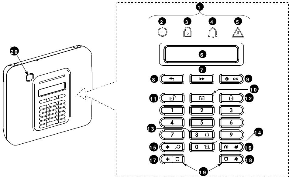
PowerMaster-10 G2 Panel Indicator and Controls
Figure 1a. PowerMaster-10 G2 Controls and Indicators
LED Indicators
| No. | Indication | Function |
| 2 | | Power (Green): Indicates that your system is properly connected to the power outlet. |
| 3 | | Arm (Red): Lights when the system is in the armed state. |
| 4 | | Chime (Green): Chime zones will chime when disturbed (see Chapter 2). |
| 5 | | Trouble (Orange): Lights when the system is in a state of trouble (see Chapter 5). |
INTRODUCTION
Control Keys
| No. | Indication | Function |
| 7 | → | NEXT: Advance from item to item within a given menu. |
| 8 | ← | BACK: Move one step back within a given menu. |
| 9 | OK | OK: Review status messages one by one and also select a displayed option. |
Arming Keys
| No. | Indication | Function |
| 12 | 8 | AWAY: Arming when nobody is at home |
| 10 | M | HOME: Arming when people remain at home. |
| 14 | 0 13 | INSTANT: Canceling the entry delay upon arming (AWAY or HOME) |
| 11 | M | DISARM / OFF: Disarming the system and stopping alarms |
| 16 | M # | PARTITION: Partition selection |
Other Keys
| No. | Indication | Function |
| 13 | 8 | Chime ON/OFF |
| 15 | * | Reviewing the event log |
| 17 | + | Emergency (hold for 2 sec.) |
| 18 | U | Fire (hold for 2 sec.) |
| 19 | + U + U | Press both buttons simultaneously for panic alarm |
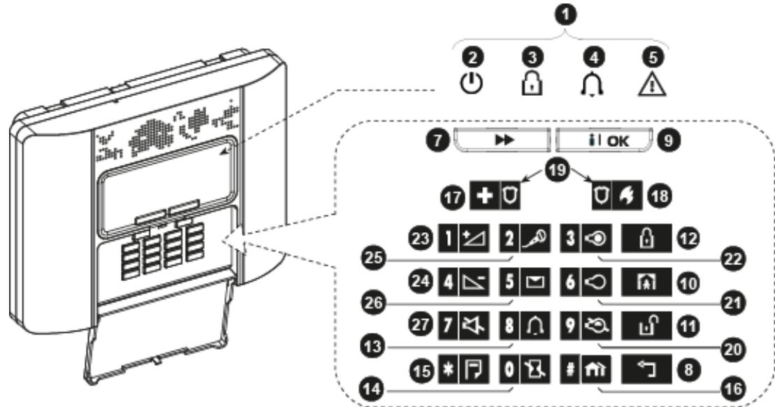
PowerMaster-30 G2 Panel Indicator and Controls
Figure 1b. PowerMaster-30 G2 Controls and Indicators
LED Indicators
| No. | Indication | Function |
| 2 | U | Power (Green): Indicates that your system is properly connected to the power outlet. |
| 3 | 9 | Arm (Red): Lights when the system is in the armed state. |
| 4 | | Chime (Green): Chime zones will chime when disturbed (see Chapter 2). |
| 5 | | Trouble (Orange): Lights when the system is in a state of trouble (see Chapter 5). |
Control Keys
| No. | Indication | Function |
| 7 | → | NEXT: Advance from item to item within a given menu. |
| 8 | ← | BACK: Move one step back within a given menu. |
| 9 | i OK | OK: Review status messages one by one and also select a displayed option. |
Arming Keys
| No. | Indication | Function |
| 12 | | AWAY: Arming when nobody is at home |
| 10 | | HOME: Arming when people remain at home. |
| 14 | | INSTANT: Canceling the entry delay upon arming (AWAY or HOME) |
| 11 | | DISARM / OFF: Disarming the system and stopping alarms |
| 16 | | PARTITION: Partition selection |
Other Keys
| No. | Indication | Function |
| 13 | 8 | Chime ON/OFF |
| 15 | * | Reviewing the event log |
| 17 | + | Emergency (hold for 2 sec.) |
| 18 | 0 | Fire (hold for 2 sec.) |
| 19 | + + + | Press both buttons simultaneously for panic alarm |
| 20 | 9 | PGM control |
| 21 | 6 | PGM output OFF |
| 22 | 3 | PGM output ON |
| 23 | 1 | Volume up * |
| 24 | 4 | Volume down * |
| 25 | 2 | Record message * |
| 26 | 5 | Play message * |
| 27 | 7 | Mute speaker * / ** |
- May not be functional on all versions of PowerMaster-30 G2.
** The Mute Speaker button is active only if the "Set Voice Option" function is enabled (see Chapter 6, section B.14).
Built-in Alarm Sounder
The PowerMaster panel has a high power siren built-in that sounds in case of alarm to deter intruders and to summon help.
The maximum operating time of the siren is configured by the installer according to local regulations.
Continuously ON when initiated by a burglar zone or a 24-hour zone, and when a user initiates a "panic alarm". When initiated by a fire zone (smoke is detected) ON - ON - ON - pause - ON - ON - ON - pause - ...... and so on. If there is nobody around to disarm the system upon alarm, the siren will sound for the time duration set by the installer - then will stop. If enabled, the strobe light will keep flashing until the system is disarmed or the siren will stop as configured by the installer.
| Alarm Type | Graphic Representation of Signal | Verbal Description of Signal |
| Burglar / 24 hour/ Panic | —— | ON continuously |
| Fire | —— —— —— —— —— —— —— | ON - ON - ON - pause - ON - ON - ON - pause...... |
| Gas (CO) | —— —— —— —— —— —— —— | ON - ON - ON - ON - pause - ON - ON - ON - ON - pause...... |
| Test* | — (both external and internal sirens) | ON for 2 seconds (once) |
- Not included in all models
General Audible Indicators
The sounds you will hear while using the control panel are:
| Sound | Definition |
| J | Single beep, heard whenever a key is pressed |
| J J | Double beep, indicates automatic return to the normal operating mode (by timeout). |
| J J J | Three beeps, indicates a trouble event |
| Success Tune (- - - ), indicates successful completion of an operation. |
| Failure Tune ( — — ), indicates a wrong move or rejection |
Other Audible Indicators²
Pre-recorded voice announcements respond to your commands by announcing what the system is doing and by prompting you to perform certain actions. They also announce alarms, troubles and identify the source of each event.
LCD Display
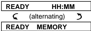
The display is a single line, backlit 16-character LCD used to display system status and events, time and date, programming instructions and also an event log file which is accompanied by the date and time of each event. The normal display alternates with the time and the system status, for example:
| READY HH:MM |
| (alternating) |
| READY MEMORY |
Screen Saver Mode
For security reasons, it is sometimes required to hide the status indication (LCD and LED display) from a potential intruder. If the Screen Saver option is enabled by the installer, then if no key is pressed for more than 30 seconds, the display will read "POWERMASTER-10 / POWERMASTER-30" and the LEDs will stop indicating any status. Pressing any key will resume the normal status display. Pressing the Fire or Emergency keys will also initiate the Fire or Emergency alarm.
If configured by the installer for additional security, the system will ask you to enter your user code as well before resuming the normal display.
When partition is enabled, the installer can configure the system so that if no key is pressed during more than 30 seconds the date and time will appear on the display.
Your system responds to valid proximity tags enrolled to the system. The proximity tag enables you to perform a variety of functions without entering user code, for example, arming, disarming, reading the event log, etc. Whenever the user code is required, you can simply present a valid proximity tag and perform the desired operation without the need to key-in your user code.
When the system is disarmed, after presenting a valid proximity tag to the control panel, the message " for AWAY" is displayed. Now you can press the OK button to immediately arm the control panel, or wait for 3 second for system automatic AWAY arming (the message "Please exit now" will be displayed). Presenting the proximity tag once again will DISARM the system.
Instead of pressing the 1 OK button (see above), you can press the >> button once / twice (the message " for HOME" / " for disarm" is displayed, accordingly) and then press the press 1 OK button for HOME arming / disarming.
Note: For UL Listed product, the proximity feature may only be used to arm or disarm the system.
Users and Codes
As a master User (User No.1) you will need a 4-digit security code to master the system (code 0000 is not allowed). You can also authorize 7 other persons (PowerMaster-10 G2) / 47 other persons (PowerMaster-30 G2) to use the system by providing them with their own security codes (see Chapter 6, B.4 Programming User Codes). Security codes are used mainly to arm and disarm the system or to access information that is restricted only to authorized users (see Chapter 6, B.4 Programming User Codes).
Moreover, you can obtain up to 8 (PowerMaster-10 G2) / 32 (PowerMaster-30 G2) multi-function portable keyfob transmitters that will allow you and the other users to easily arm, disarm and control the system without accessing the panel, including from outside the premises (see Chapters 2 and 6, B.7 Add / Delete Keyfob Transmitters).
The Duress Code enables you to disarm the system using a special code that sends a silent alarm to the monitoring station (See chapter 2).
2. Operating the PowerMaster System
For more information regarding terms used in this chapter, refer to APPENDIX C. GLOSSARY.
Note: This manual displays PowerMaster-10 G2 panel buttons only, even when instructions refer to both panels. When an instruction refers to PowerMaster-30 G2 only, the PowerMaster-30 G2 panel buttons are displayed.
Basic Arming and Disarming
Following are a set of procedures for performing basic arming and disarming of the alarm system.
Preparing to Arm
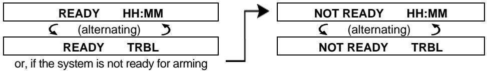
Before arming, make sure that READY is displayed.
| READY HH:MM | This indicates that all zones are secured and you may arm the system as desired. |
| If at least one zone is open (disturbed) the display will read: |
| NOT READY HH:MM | This indicates that the system is not ready for arming and in most cases that one or more zones are not secured. However, it can also mean that an unresolved condition exists such as certain trouble conditions, jamming etc., depending on system configuration. |
To review the open zones click OK. The details and location of the first open zone detector (usually an open door or window sensor) will be displayed. To fix the open zone, locate the sensor and secure it (close the door or window) - see "device locator" below. Each click of OK will display another open zone or trouble indication. It is highly recommended to fix the open zone(s), thus restoring the system to the state of "ready to arm". If you do not know how to do this, consult your installer.
Note: To quit at any stage and to revert to the "READY" display, click
Device Locator: The PowerMaster system has a powerful device locator that helps you to identify open or troubled devices indicated on the LCD display. While the LCD displays an open or faulty device, the LED on the respective device flashes indicating "it's me". The "it's me" indication will appear on the device within max. 16 seconds and will last for as long as the LCD displays the device.
Arming 'AWAY' / 'HOME'
If the system is READY and/or Forced Arming is enabled proceed as shown below. For more information on Forced Arming, see "Forced Arming AWAY or HOME" below.
If the system is NOT READY and Forced Arming is not permitted, review any open zone detectors to locate and secure them.
If you want to arm using partitions, see "Partition Selection Process" and then proceed as shown below. If the user has changed the state of the system from a high security mode to a lower security mode i.e. from ARM to DISARM, or from ARM to HOME, he will be prompted to enter the user code thus bypassing the QUICK ARM option.
| PRESS | RESULTING DISPLAY |
| If Quick Arm is disabled | ARMING AWAY/HOME |
| PRESENT TAG OR
ENTER CODE |
| PLEASE EXIT NOW |
| Vacate the premises (ARM AWAY) OR
Move to interior zone (ARM HOME) | ↓ (Exit delay) ↓ |
| AWAY/HOME |
ARM indicator lights steadily during the armed state.
Disarming and Stopping Alarm
Enter the protected premises via a delayed zone. Upon detecting your entrance, the system will start sounding the entry delay beeps alerting you to disarm the system before the entry delay ends.
After disarming, different displays may appear indicating that the system is in a state of alarm MEMORY. The MEMORY message will disappear only upon rearming the system. To disarm the system, proceed as shown:
| PRESS | RESULTING DISPLAY |
| [Enter Code] / [Present tag] | PRESENT TAG OR ENTER CODE Code / Present gag |
| READY HH:MM |
ARM indicator extinguishes during the disarmed state. Disarming the system also stops the siren alarm, irrespective of whether the alarm was initiated during the armed or the disarmed state.
Disarming under Duress
If you are forcibly compelled to disarm the system, enter the duress code (2580 by default) or another code set by the installer. Disarming will take place normally but a silent alarm will be transmitted to the monitoring station.
Partition Selection Process
Access to any desired partition is achieved through the use of an individual code or proximity tag. It is not possible to access the INSTALLER MENU if one or more partitions are in the AWAY or HOME modes. Before attempting to perform any operation on any given partition(s), it is necessary to perform the operation below which enable you to select the desired/allowed partition(s) using the individual code or proximity tag:
| PRESS | RESULTING DISPLAY |
| # | SELECT PARTITION |
| Enter partition # (1 - 3) | PARTITION 1 |
Note: The "Failure Tune" will be heard when selecting a partition to which no sensors / peripherals were enrolled.
Special Arming & Disarming Options
In addition to basic arming, PowerMaster provides you with several advanced arming and disarming options:
Switching from 'HOME' to 'AWAY'
You do not have to disarm the system - just press. The response will be the same as in ARMING AWAY above. Vacate the premises before the exit delay expires.
Switching from 'AWAY' to 'HOME'
You do not have to disarm the system - just press. Since this operation reduces the security level, PowerMaster will ask you to key in your master user code or user code, thus making sure that you are an authorized user.
| PRESS | RESULTING DISPLAY |
| [Enter code] / [Present tag] | PRESENT TAG OR ENTER CODE Code / Present tag |
| ARMING HOME |
| Move to interior zone | ↓ (Exit delay) ↓ |
| ARM HOME HH:MM |
ARM indicator flashes during the armed state.
Arming AWAY or HOME 'Instant'
Pressing 0 during the exit delay will arm the system in the "Instant" mode, i.e. without an entry delay. Therefore, any detection in any zone will trigger an immediate alarm. To arm AWAY-INSTANT, proceed as follows.
ARM indicator lights during the armed state.
Forced Arming AWAY or HOME
Forced arming allows you to arm the system even if the system is "NOT READY". Any open zones will be bypassed for the duration of arming.
Note: When forced arming is carried out, the buzzer "protests" by emitting a continuous tone during the exit delay until the last 10 seconds of the delay. You can silence this signal by pressing the arming button again. If forced arming is enabled and you wish to arm the system when NOT READY is displayed, proceed as shown:
| PRESS | RESULTING DISPLAY |
| [Enter code] / [Present tag] | PRESENT TAG OR ENTER CODE Code / Present tag |
| ARMING AWAY |
| PLEASE EXIT NOW |
| (to mute the buzzer) | ↓ (Exit delay) ↓ |
| Vacate the premises | AWAY |
ARM indicator lights during the armed state.
| Remember: Forced arming compromises security!! |
| Forced arming “HOME” is performed in a similar manner, as follows: |
| PRESS | RESULTING DISPLAY |
| [Enter code] / [Present tag] | PRESENT TAG OR ENTER CODE Code / Present tag |
| ARMING HOME |
| PLEASE EXIT NOW |
| (to mute the buzzer) | ↓ (Exit delay) ↓ |
| Go to interior zone | HOME HH:MM |
ARM indicator flashes during the armed state.
Arming in the Latchkey Mode
This mode, if enabled by the installer, is useful for a parent at work who wants to be sure that his children have returned from school and have disarmed the system. A special "latchkey" message will be sent out when the system is disarmed by a "latchkey user".
Latchkey users are holders of user codes or users of keyfob transmitters 5 through 8 (PowerMaster-10 G2) / 23-32 (PowerMaster-30 G2). The latchkey message is considered an alert and not an alarm, and is therefore sent to the private telephones programmed by the user as targets for alert messages.
Latchkey arming is possible only when you arm "AWAY". To arm in the Latchkey mode, proceed as follows:
| PRESS | RESULTING DISPLAY |
| ARMING AWAY |
| ARMING LATCHKEY |
| (Within 2 seconds) | (alternating) |
| Vacate the premises | PLEASE EXIT NOW |
| ↓ (Exit delay) ↓ |
| AWAY |
Note: Latchkey must be enabled by your installer.

ARM indicator lights during the armed state.
Initiating Alarms
Following are various methods that may be used for initiating alarms.
Initiating Panic Alarm
You can generate a panic alarm manually in the disarmed and armed states. The sequence will be as shown:
| PRESS | RESULTING DISPLAY |
| + U U simultaneously | PANIC ALARM |
| READY HH:MM |
To stop the alarm, press the button and then key in your valid user code.
Initiating Fire Alarm1 or Emergency Alarm
You can generate a fire alarm or a silent emergency alarm in disarmed & armed states, as follows:
| PRESS | RESULTING DISPLAY |
| OR
+ U
for 2 seconds | FIRE ALARM |
| EMERGENCY |
| Then, if or when the system is in the disarmed state: |
| READY HH:MM |
| (alternating) |
| READY MEMORY |
To stop the alarm, press and then key in your valid user code.
Note: For UL Listed product, Emergency is ancillary use only.
Disable / enable the chime zones (see Appendix C) by alternate clicking of the 8 key, as shown below:
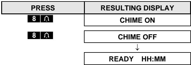
CHIME indicator lights steadily when "chime on" is selected.
Note: For UL Listed Product, the Chime setting must be set to "Chime ON".
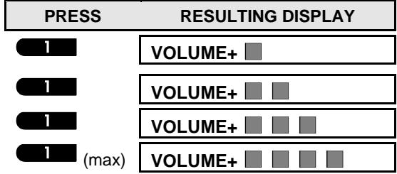
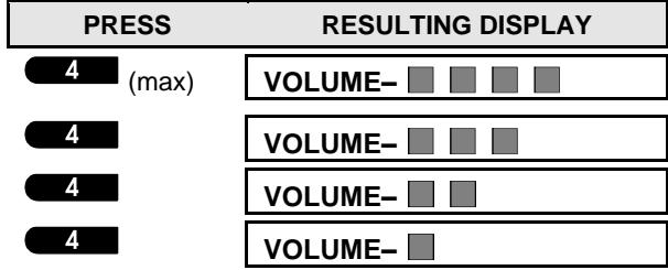
Adjusting the Speech Volume1 and the Volume of the Keypad Beeps
The following diagrams show how to increase or decrease the loudness by clicking the <1> or <4> key (assuming that the volume was at minimum/maximum to begin with).
3. Speech and Sound Control1
The sound and speech-related functions offered by the control panel are controlled with the keypad, as detailed in the following list.
When partitioning is enabled:
Sound and speech-related features only apply to the partition(s) where the control panel is present. An activity performed via the control panel from another partition will be displayed and the LED will light. The operation will be added to the log file but will not be heard over the control panel speaker.
Key Function
Increases the loudness of spoken messages
Decreases the loudness of spoken messages
7 Enables / disables the loudspeaker
2 Records a spoken message for other users of the alarm system
5 Allows listening to a recorded message left by another user of the alarm system
8 Enables / disables the chime function in chime zones
Voice ON/OFF
You can switch spoken announcements on and off by alternate clicking of the <7> key, as shown below.
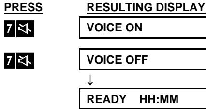
Note: The system will maintain the "Voice OFF" state until subsequent selection of "Voice ON".
Message Exchange
For message exchange you can record a verbal message for other users of the alarm system. Face the panel, press <2> and keep it pressed. When the display reads TALK NOW, start talking. The 5 dark boxes will slowly disappear one by one, from right to left, as shown in the diagram below.
ACTION RESULTING DISPLAY


SPEECH AND SOUND CONTROL
Once the last of the boxes disappears, RECORDING ENDED will be displayed.
When you release the button, the display will revert to the normal status-displaying mode, but will also indicate that a message is waiting. For example:
| READY HH:MM |
| (alternating) |
| READY MSG |
To check your own message, listen to it within one minute from the end of recording (see the next section - Message Playback). This way the MSG indication will not be erased.
Message Playback
To listen to a message left by another user of the system:
Click 5 and listen. PLAY will be displayed and the message will be played back over the built-in
loudspeaker. When the playback ends, the display will revert to the normal status-displaying mode. If more than 1 minute elapsed after recording, the MSG indication will disappear.
4. Electrical Appliance Control
The system allows manual or automatic remote control of a device connected to the PGM output.
The user defines the ON and OFF times via the Scheduler (see Chapter 6 - B.14 Programming the Scheduler). The installer determines which zone sensors will switch the remote controlled appliances on and off. However, the decision whether the remote controlled appliance will respond as programmed is up to you (see next table).
Key Function
3 Manual activation of a light or other household electrical appliance that is connected to PGM output.
6 Manual deactivation of a light or other household electrical appliance that is connected to PGM output.
9 Selecting the active automatic control method:
- Sensors: The appliance is controlled by sensors (assigned by the installer for this).
Timer: The appliance is controlled by timer (ON and OFF times are defined by the installer).
Both: The appliance is controlled by sensors as well as by a timer.
Examples of benefits gained by automatic remote control:
- Timer Control. When you are away, the timed activation / de-activation of an electrical appliance.
- Zone Control. Upon disturbance of a perimeter zone, the electrical device is switched on.
Notes:
- Automatic activation and deactivation of electrical appliance depends also on the Scheduler setup (see Chapter 6 - B.14 Programming the Scheduler).
- PGM not to be enabled in UL Listed Product.
Automatic ON/OFF Control
You can select two of four options:
- By Timer ON
- By timer OFF
- By sensor ON
- By sensor OFF
The presently active options are shown with a dark box (■) at the far right. To view the 2 other options click the button.
A presently inactive option is shown without a dark box at the far right. The dark box will appear if you click OK while the option is displayed. A "Success Tune" indicates successful saving of a new option.
PRESS
9
If not satisfied - press 9
If satisfied - press OK
OK
9
If not satisfied - Press 9
If satisfied - OK
OK
9
RESULTING DISPLAY
BY TIMER ON
(If this is the default)
BY TIMER OFF
BY TIMER OFF
BY TIMER OFF
BY SENSOR ON
BY SENSOR OFF
BY SENSOR OFF
BY SENSOR OFF
READY HH:MM


5. Reviewing Troubles and Alarm memory
Alarm & Tamper Memory Indication
The PowerMaster retains in its memory alarm and "tamper" events that occurred during the last arming period. Note: Alarm events are memorized only after the "abort period" (see Appendix C). This means that if you disarm the system immediately - before the abort period expires - there will be no memory indication
A. Indication of Alarm & Tamper Condition
If the system is disarmed following an alarm event, a flashing MEMORY message will be displayed, as follows:
To review memory content, click OK button.
EXAMPLE: An alarm was triggered because the garage door - zone No. 12 - was opened but then closed. In addition, the bedroom motion detector - zone No. 7 - sent a "Tamper" message because its cover had been removed.
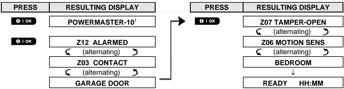
In response to additional clicking of the OK button, the display shows details of other events retained in open tamper (if any), or reverts to its initial state (see A above).
If the system is NOT READY, the display will first read the open zones and then alarm memory events.
Clearing the Memory Indication
To clear the 'Memory' indication you must first review the cause of alarm as described above. Once you return to the 'Ready' screen simply press Away and enter the code if requested, then press Disarm followed by the code. The memory message will now clear. Otherwise the memory indication and content will be cleared upon the next arming of the system.
Troubles
A. Indication of Trouble condition
If the system detected a trouble condition in any of the enrolled devices, the TROUBLE indicator illuminates, 3 beeps are sounded once per minute and a flashing TRBL message is displayed, as follows.
All trouble messages need to be reviewed and corrected as described below:
EXAMPLE: The kitchen device - zone No. 9 - has reported a low battery - the living room device zone No. 15 has been inactive, and an attempt to communicate a message to your telephone has failed. However, these troubles do not prevent the system from being "ready to arm".
To review the source of the current troubles one by one, click the OK button repeatedly as shown below:
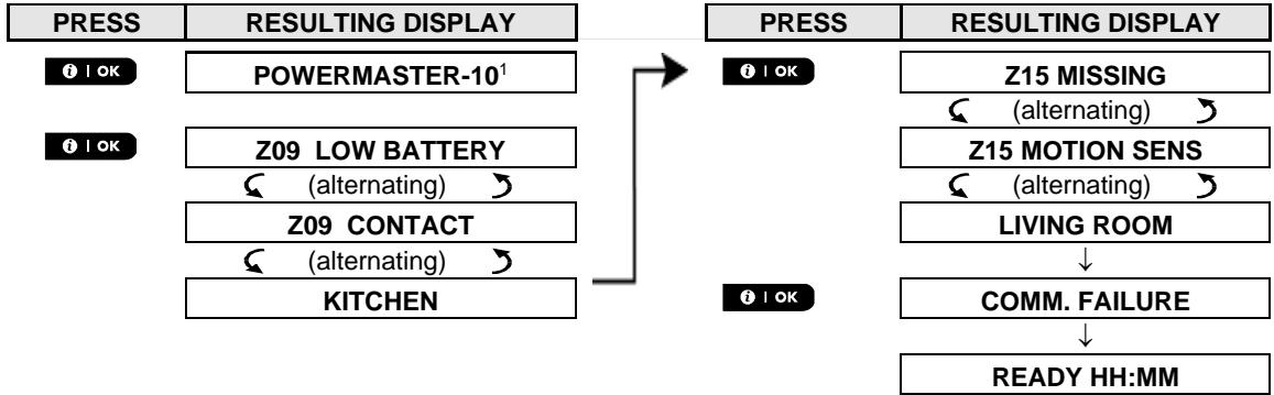
IMPORTANT! If the trouble beeps bother you, disarm the system again (even though it is already disarmed). This will cancel the trouble beeps for 4 hours.
C. Reviewing Memory & Troubles at the Same Time
If alarms / tamper events are retained in the alarm memory and at the same time a state of trouble exists, the display will first read the alarm memory followed by trouble events, as described in sections A & B above.
General Indications
Cellular connection indications
After all trouble messages have been reviewed and if a SIM card is installed in the panel, the PowerMaster displays the following indications:
GSM signal strength: indicated as CELL RSSI STRONG / CELL RSSI GOOD / CELL RSSI POOR.
Network Type: indicates the type of network the cellular modem is registered to. Represented by two characters, for example 2G or 3G.
- Cellular Provider: indicates the name of the cellular provider, which the cellular modem is registered to. Represented by 13 characters, for example Orange.
If a PIR camera is enrolled in the system, "GPRS initialize" is displayed following panel power-up to indicate that the modem is undergoing initialization. This message appears at the end of all TRBL messages and immediately following the GSM signal strength indication if a SIM card is installed.
Correcting Trouble Situations
The trouble indications (illuminated TROUBLE indicator and flashing TRBL message) are cleared once you eliminate the cause of trouble. The table below describes the system faults and respective corrective actions. If you do not know how to correct a trouble situation, report it to your installer and seek his advice.
| Fault | What it means |
| 1-WAY | The device functions but cannot "hear" the panel. The control panel cannot configure or control the device. Battery consumption increases. |
| AC FAILURE | There is no power supplied to the device. |
| CLEAN ME | The fire detector must be cleaned |
| COMM. FAILURE | A message could not be sent to the monitoring station or to a private telephone (or a message was sent but was not acknowledged) |
| CPU LOW BATTERY | The backup battery within the control panel is weak and must be replaced (see Chapter 10. Maintenance, "Replacing Backup Battery"). |
| CPU TAMPER OPEN | The control panel was physically tampered with or its cover was opened, or it was removed from wall. |
| GAS TROUBLE | Gas detector failure |
| GSM NET FAIL | The cellular communicator is not able to connect to the cellular network. |
| JAMMING | A radio-frequency signal which is blocking all communication frequency channels between the sensors and control panel is detected. |
| LINE FAILURE | There is a problem with the telephone line |
| LOW BATTERY | The battery of the indicated device is near the end of its useful life. |
| MISSING | A device or detector has not reported for some time to the control panel. |
| NOT NETWORKED | A device was not installed or not installed correctly, or, cannot establish communication with the control panel after installation. |
| RSSI LOW | The GSM communicator has detected that GSM network signal is weak |
| SIREN AC FAILURE | There is no power to the siren |
| TAMPER OPEN | The sensor has an open tamper |
| TROUBLE | The sensor reports trouble |
| SOAK TEST FAIL1 | Detector alarms when in Soak Test mode |
6. Menus and Functions
This chapter explains the user programming features of your PowerMaster system and allows you to tailor the PowerMaster system according to your specific needs. The chapter is divided into three sections, as follows:
Part A - Guides you how to enter/exit the User Settings menu and how to select the desired setting options.
Part B - Guides you to execute the selected settings.
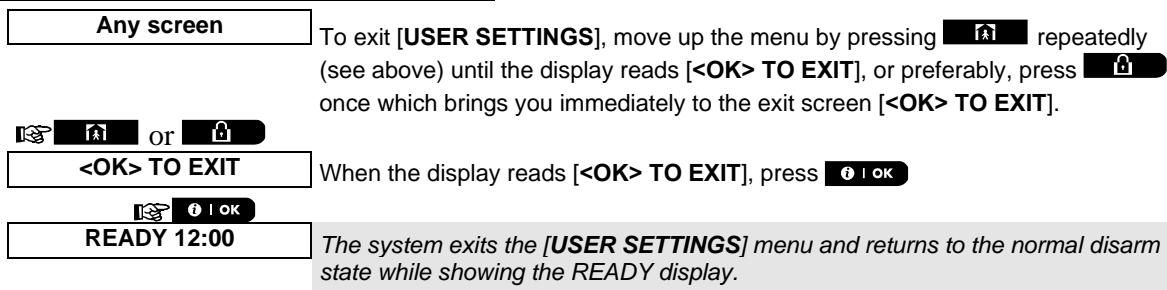
| The following procedure describes how to enter and move within the User Settings menu.
Detailed descriptions of the User Settings options are provided at the end of the procedure.
To exit the User Settings menu – see section A.2. |
| 1. You can enter the "USER SETTINGS" menu only when the system is disarmed.
2. Carefully read the section titled "Additional Information" according to the indicated references 1 etc. – see table at end of this section. |
Note: This manual displays PowerMaster-10 G2 control panel buttons only, even when instructions refer to both control panels. When an instruction refers to PowerMaster-30 G2 only, the PowerMaster-30 G2 control panel buttons are displayed.
| 1. | READY 00:00 | Make sure the system is disarmed and then press the >> button repeatedly until the display reads [USER SETTINGS].1 |
| 2. | USER SETTINGS | Press OK |
| OK |
| Present TAG OR ENTER CODE: | The screen will now prompt you to enter your user code or present your proximity tag. |
| 3. | CODE | Enter your User Code.2 |
| SET BYPASS | The display reads the first Setting option of the User Settings menu [SET BYPASS].3 |
B. To Select a Setting Option
| 4. | SET BYPASS | Click the >> or ← button until the display reads the desired setting option, for example, "TIME & FORMAT". |
| 5. | TIME & FORMAT | When the desired setting option appears on the display, press the OK button to enter the setting process. |
| Continue to the selected setting option in B.1 - B.16 | The remainder of the procedures for the selected setting options is pro in sections B.1 to B.16. |
| Additional Information (section B.1) |
| 1 | Display shown in disarm state when all zones are secured (00:00 or other digits show present time). |
| 2 | a. If you have not already changed your personal code number, use the default setting – 1111.
b. Master User has access to all User Settings options. Other users have access only to the Bypass options.
c. If you enter an invalid user code after 3 times, and after each next retry, the keypad will be automatically disabled for a pre-defined period of time and the message WRONG
password will be displayed. |
| 3 | The bypass options will be displayed in the User Settings menu only if enabled by the installer. Otherwise, the first User Settings option displayed will be [USER CODES]. |
EVENT REPORTING & CONTROL BY TELEPHONE AND SMS
Click until the display reads the desired setting option and then press OK.
| SET ZONE BYPASS | Use to set the Zone Bypass Scheme i.e. to bypass (exclude) faulty or unsecured ("disturbed") zones, or to clear a bypassed zone (unbypass). For further details and programming procedure see section B.1.3 |
| REVIEW BYPASS | Use to quickly review the Bypass Scheme i.e. which zones are bypassed. For further details and reviewing procedure see section B.2.3 |
| RECALL BYPASS | Use to Recall the last used bypassed scheme for reuse in next arming period. For further details and recalling procedure see section B.3.3 |
| USER CODES | Use to program your Master User secret access code and the seven codes of the other users. For further details and programming procedure see section B.4. |
| DURESS CODE1 | Use to program the Duress (ambush) code. For further details and programming procedure see section B.5. |
| PROXIMITY TAGS | Use to add new Proximity Tags to or to delete Proximity Tags when lost. For further details and programming procedure see section B.6. |
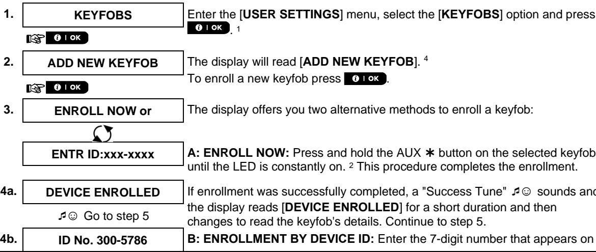
| KEYFOBS | Use to add new Keyfob Transmitters or to delete Keyfob Transmitters when lost. For further details and programming procedure see section B.7. |
| TIME & FORMAT | Use to set the time clock to show the correct time and time format. For further details and programming procedure see section B.8. |
| DATE & FORMAT | Use to set the calendar date to show the correct date and date format. For further details and programming procedure see section B.9. |
| AUTO-ARM ENABLE | Use to enable or disable the Automatic Daily Arming option at predefined times (see Auto-Arm Time setting). For further details and programming procedure see section B.10. |
| AUTO-ARM TIME | Use to set the predetermined time for the Automatic Daily Arming if enabled (see Auto-Arm Enable setting). For further details and programming procedure see section B.11. |
| PRIVATE REPORT | Use to program the four private telephone numbers for reporting alarm and other event messages to private subscribers. For further details and programming procedure see section B.12. |
| SQUAWK | Use to enable or disable the squawk sound i.e. arm / disarm feedback indication. For further details and programming procedure see section B.13. |
| SCHEDULER | Use to set the daily / weekly time schedule for start & stop activation of devices connected to the PGM output. For further details and programming procedure see section B.14. |
| VOLUME CONTROL | Use to adjust the volume level of the various system beeps, chime signal and voice prompts, and to enable or disable the Voice option. For further details and programming procedure see section B.15. |
| SERIAL NUMBER | Use to read the system serial number and similar data see section B.16. |
| PLINK curr. Params | Use to display the current IP addresses of the PowerLink. |
| <OK> TO EXIT | Use to exit from the "USER SETTINGS" menu back to Main Menu. For further details see section A.2. |
| Returns to first option | |
1 Duress Code is not applicable for UL installations
During the setting process it is frequently necessary to return to the previous setting step or option (i.e. "to go one level up") or to exit the User Settings menu.
A. To Move One Level Up
To move one level up during the setting process, click once or more. Each click will take you one level up or to the previous setting step:
The keypad's buttons are used for various functions when programming. The following table provides a detailed description of the function or use of each button.
| Button | Definition | Navigation / Setting Function |
| NEXT | Use to move / scroll forward to the next menu options. | |
| BACK | Use to move / scroll backward to the previous menu options. | |
| OK | Use to select a menu option or to confirm a setting or action. | |
| HOME | Use to move one level up in the menu or to return to previous setting step. | |
| AWAY | Use to jump back to the [<OK> TO EXIT] screen to quit programming. | |
| OFF | Use to cancel, delete, clear or erase setting, data, etc. | |
| 0-9 | | Numerical keypad used to enter numerical data. |
| PARTITION SELECTION | Use to change the status of partitions when programming user codes. | |
B.1 Setting the Zone Bypass Scheme
Bypassing permits arming only part of the system while allowing free movement of people within certain zones when the system is armed. It is also used to temporarily remove from service faulty zones that require repair work or to deactivate a sensor if, for example, you are decorating a room.
Here you can set the Zone Bypass Scheme i.e. to scroll through the list of registered (enrolled) sensors to your PowerMaster system and to Bypass (deactivate) faulty or disturbed sensors (either READY or NOT-READY) or to Clear (reactivate) BYPASSED zones (sensors).
Once you have set a Bypass Scheme you can use the following 3 options:
To quickly review the bypassed zones – refer to section B.2.
To quickly clear a bypassed zone i.e. to reactivate the bypassed zone – refer to section B.1.
To repeat (recall) the last used zone bypassing scheme – refer to section B.3.
Note: For UL Listed Product, zone bypassing must be conducted on an individual basis each time the system is armed.
EVENT REPORTING & CONTROL BY TELEPHONE AND SMS
①
- Zones will be bypassed throughout one disarm-arm period only. Disarming the system after arming will suspend the entire bypassing scheme but you can recall and reuse it as described in section B.3.
- Fire zones cannot be bypassed.
- Carefully read the section titled "Additional Information" according to the indicated references 1 etc. - see table at end of section B.3.
REMEMBER - ZONE BYPASSING COMPROMISES SECURITY!
A. To Bypass a Zone
- SET ZONE BYPASS
Enter the [USER SETTINGS] menu1, select the [SET ZONE BYPASS]2 option and press OK.

Z01: READY
The first zone, Z01, is displayed.

Z01: P1■ P2 P3

Living Room
- or
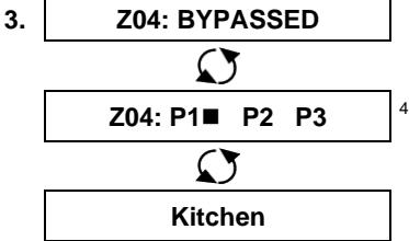
Click the or button until the display reads the zone you wish to bypass (or clear bypass), for example, "Z04" for Zone 04. After several seconds the LED on the respective device starts flashing indicating "it's me".

Z04: P1■ P2 P3

- Kitchen
When the display reads the zone you wish to bypass press OK

- TO BYPASS
The display now reads [ OK TO BYPASS]. 5

To bypass the selected zone press OK
- Z04: BYPASSED
A "Success Tune" sounds and the updated zone status is now displayed i.e. [Z04: BYPASSED].8
B. To Clear a Bypassed Zone
- Z04: BYPASSED

Z04: P1■ P2 P3

- Kitchen

TO CLEAR
Repeat steps 1 to 2 above.
8.
Z04: READY
When the zone you wish to clear bypass appears on the display (for example, "Z04"), press OK to confirm. You can also identify the device by looking for the "it's me" LED indication on the displayed device.
The display now reads [ OFF TO CLEAR].5
To clear the bypassed zone, press the button.
A "Success Tune" sounds and the updated zone status is now displayed, i.e. [Z04: READY] or [Z04: NOT READY].9
B.2 Reviewing the Zone Bypass Scheme
Here you can quickly review the Bypass Scheme i.e. the zones that are set to be bypassed during the next arming session.
-
REVIEW BYPASS Enter the [USER SETTINGS] menu and select the [REVIEW BYPASS] option and press OK.2
-
BYPASS LIST The display reads [BYPASS LIST] Click the or ← buttons repeatedly to review all bypassed zones in ascending numerical order. When done, click to exit.
B.3 Recalling the Zone Bypass Scheme
Use this option to repeat (recall) the most recent Bypassed Scheme for use during the next arming session.
- RECALL BYPASS Enter the [USER SETTINGS] menu, select the [RECALL BYPASS] 1 option and press OK 2,6
- TO RECALL The display now reads [ TO RECALL].7 OK To recall the last used bypass scheme press OK
- Bypass RECALLED A "Success Tune" sounds. The display reads [Bypass RECALLED] and then returns to "USER SETTINGS" step 1.
| Additional Information (section B.1 - B.3) |
| 1 | For detailed instructions on how to select User Settings –refer to sections A.1 and A.2. |
| 2 | This menu is displayed only if "BYPASS" was previously enabled by the installer. |
| 3 | a. The STATUS to the right of the zone number indicates whether the zone is READY, NOT-READY or BYPASSED.
b. In the example on the left the display reads [Z01: READY] alternating with [Living Room]. |
| 4 | This display will appear only if PARTITIONING was previously enabled. |
| 5 | a. If the zone you selected is "not bypassed", the display prompts you to press [<OK> TO BYPASS]. However, if the zone you selected is already "bypassed", the display prompts you to press [<OFF> TO CLEAR].
b. To abort and return to the previous step press ➔ or ⇕ |
| 6 | This menu is not displayed if Partition is enabled. |
| 7 | The display now prompts you to press [<OK> TO RECALL] i.e. to repeat the last used bypass scheme. To abort and return to the User Settings menu, press ⇑. |
| 8 | You can now repeat steps 2 - 5 to bypass or clear another zone. To end this session and to select other menu options or to quit programming - follow the instructions in section A.2. |
| 9 | You can now select another option in the User Settings menu (see section A.1), or quit programming (see section A.2). |
B.4 Programming User Codes
PowerMaster system allows you to authorize up to 8 people (PowerMaster-10 G2) / 48 people (PowerMaster-30 G2) to arm and disarm the system by providing each with a unique 4 digit personal security code, and assigning them with different security levels and functionalities. Moreover, you can obtain up to 8 (PowerMaster-10 G2) / 32 (PowerMaster-30 G2) multi-function portable keyfob transmitters that will allow you and the other users to easily arm, disarm and control the system without accessing the panel, including from outside the premises (see section B.7 Add / Delete Keyfob Transmitters). The Duress Code enables you to disarm the system using a special code that sends a silent alarm to the monitoring station.
There are two types of users: Master User and User. The table below summarizes the different operations that can be performed by different users:
| User type | Function |
| Master User | Arm/disarm |
| Zone bypass |
| Authorize other user codes |
| Set user codes |
| Report to private |
| Enroll/delete proximity tag |
| Enroll/delete keyfob |
| Automatic arming |
| Enable squawk |
| Set date and time format |
| Read event log |
| Programming the duress code |
| Programming the scheduler |
| Enabling/disabling voice option |
| Adjusting volume of system beeps, chime signal and voice prompts, |
| User | Arm/disarm |
| Zone bypass options |
The user codes are assigned as follows:
```java
User Code 1 is assigned to the Master User of the system (i.e. the owner). It is the only user code that allows access to the User Settings menu. The default setting of the Master User code is 1111. This code cannot be erased and must be replaced with a secret code as soon as possible.
User Codes 2-4 (PowerMaster-10 G2) / User Codes 2-22 and 33-48 (PowerMaster-30 G2) are assigned to family members, co-workers etc. They enable arming and disarming of the system or of selected partitions as defined by the Master User. They can access the "User Settings" menu only for "zone bypassing" provided this option is enabled in the Installer menu.
User Codes 5-8 (PowerMaster-10 G2) / User Codes 23-32 (PowerMaster-30 G2) are the same as user codes 2-4 / 2-22 but can be assigned to "Latchkey" (child monitor) users. For a detailed explanation of the Latchkey application see Chapter 2 (Arming in the Latchkey Mode) and Appendix C.
Partition Option (For information about Partition option - see Appendix B)
Your alarm system can divide zones into up to 3 parts (groups) via the installer menu. These parts are designated as partitions P1, P2 & P3. Each partition can be armed and disarmed separately providing protection to selected parts of the premises.
Each user out of the 8 (PowerMaster-10 G2) / 48 (PowerMaster-30 G2) system users can be authorized by the Master User to arm and disarm any combination of partitions including all 3 partitions.
Here you can program (or edit) the 8 (PowerMaster-10 G2) /48 (PowerMaster-30 G2) User Codes and thereby define which of these will be authorized to arm and disarm.
(1)
- The default setting 1111 of the Master User Code is the same for all PowerMaster systems and is known to many other people. Therefore, we highly recommend that you immediately replace it with a unique secret code. Never set any user code the same as any installer code.
- Code "0000" is not valid! Do not use it.
- The duress code (2580 by default), which is set in the installer menu, cannot be selected as a normal user code. Any attempt to program it will be rejected by the system.
- Carefully read the section titled "Additional Information" according to the indicated references 1 etc. - see table at end of this section.
EVENT REPORTING & CONTROL BY TELEPHONE AND SMS
A. To Program a User Code
- USER CODES
1 OK
- User 01 Code The first user code "User 01 Code" is displayed.
12/14
12/12
0
m = 311
13/14
Enter the [USER SETTINGS] menu, select the [USER CODES] option and press OK.1
The first user code "User 01 Code" is displayed.
At the blinking cursor position, key in the User Code you wish to program, for example, [06] for user code 6, or alternatively click the or button until the display reads, [User 06 Code].
- User 06 Code When the user code you wish to program appears on the display, press
0
1
DK
m = 311
OK
- User 06 : ■234 To program or edit the code, at the blinking cursor position enter the 4 digit code, for example, "1234", using the numerical keypad. ^3,4
5.
0
1
DK
m = 311 ;
To program or edit the code, at the blinking cursor position enter the 4 digit code, for example, "1234", using the numerical keypad.3, 4
When done, press
0
0
<
)
User 06 : 1234
R
e
U
n
tc
st
ep
A "Success Tune" sounds. The display confirms the saved code. 5, 6
B. To Set Partitions Authorization1
- SET PARTITIONS
OK
- U06: P1■ P2 P3
U06:P1■P2P3■
OK
Return to step 3
The display will read [SET PARTITIONS].7
Use the key pad keys 1, 2, 3 to change the status of the partitions P1, P2 & P3, respectively.
When you are satisfied with the setting, for example, User 6 is authorized with Partition 1 and 3 only, press OK to confirm.
A "Success Tune" sounds. The display confirms the Partition setting.
| Additional Information (section B.4) |
| 1 | For detailed instructions on how to select the setting options – refer to sections A.1 and A.2. |
| 2 | The display shows the 1stUser Code (Master User) in the list of 8 User Codes (in PowerMaster-10 G2 system) / 48 User Codes (in PowerMaster-30 G2). If you have not yet changed the default code 1111, we recommend that you change it now. |
| 3 | a. The display shows the user code currently programmed in this location (e.g. 5327).
b. The cursor blinks on the first digit of the code.
c. If the location is free the display will be blank (- - - ). |
| 4 | You can move the cursor to the next or previous digit by pressing → or ← . Pressing ← erases the digit of the cursor + all digits right of the cursor. |
| 5 | a. The new code is momentarily displayed without the cursor before reverting to step 3.
b. If Partition is enabled, continue to step 6. |
| 6 | You can now repeat steps 3 - 5 to program or edit another user code. To end this session and to select other menu options or to quit programming – follow the instructions in section A.2. |
| 7 | This setting can be performed only after completing steps 1 - 5 of section B.4A. |
| 8 | The ▪ symbol now appears next to the newly selected Partitions. |
| 9 | You can now repeat steps 3 - 7 to program or edit another user code. |
B.5 Programming the Duress Code1
A duress (ambush) alarm message can be sent to the Monitoring Station if you are forced to disarm the system under violence or menace. To initiate a duress message, you must disarm the system using a duress code (2580 by default).
A. To Program the Duress Code
- DURESS CODE Enter the [USER SETTINGS] menu, select the [DURESS CODE] option and press OK
- DURESS CODE 2580 At the blinking cursor position, key in the Duress Code you wish to program, for example, 6973.2,3
- DURESS CODE 6973 When the duress code you wish to program appears on the display, press OK
±b Return to step 1
A "Success Tune" sounds. The display confirms the saved code.4
| Additional Information (section B.5) |
| 1 | For detailed instructions on how to select the setting options – refer to sections A.1 and A.2. |
| 2 | The display shows the default duress code (2580). |
| 3 | Do not set the duress code the same as an installer or user code. |
| 4 | To end this session and to select other menu options or to quit programming – follow the instructions in section A.2. |
A proximity tag may be assigned to each of the PowerMaster-10 G2 user codes 1-8 / PowerMaster-30 G2 user codes 1-32 that can be used instead of the user codes to perform a variety of functions, for example, arming, disarming, reading the event log, etc.
Whenever a user code is required you can simply present a valid proximity tag instead of entering the user code. Each tag should be assigned with a serial No. 1-8 (PowerMaster-10 G2) / 1-32 (PowerMaster-30 G2) that corresponds to the User Code No. 1-8 (PowerMaster-10 G2) / 1-32 (PowerMaster-30 G2) and enrolled into the system correspondingly.
The partition* authorization of the tags is identical to their corresponding user codes. For example, proximity tag 3 is assigned to user code 3.
Here you can add (enroll) new proximity tags or delete tags as required.
Carefully read the section titled "Additional Information" according to the indicated references1 etc. - see table at end of this section.
A. To Add (Enroll) a Proximity Tag
- PROXIMITY TAGS Enter the [USER SETTINGS] menu, select the [PROXIMITY TAGS] option and press OK 1
- ADD NEW TAG The display will read [ADD NEW TAG]. 3 To begin the process of enrolling a new proximity tag press OK
- ENROLL NOW or ENTR ID:xxx-xxxx Present the proximity tag to the control panel within the timeout period.
EVENT REPORTING & CONTROL BY TELEPHONE AND SMS
- DEVICE ENROLLED
Go to step 5
- T01:Tag (Prox)

T05:Tag (Prox)

OK
Return to step 2
If enrollment was successfully completed, a "Success Tune" sounds and the display reads [DEVICE ENROLLED] for a short duration and then changes to read the tag's details.
The display shows the allocated tag serial No (user No.), which is always the first free number, for example: [T01:Tag (Prox)].
To assign the tag to another user, for example, "User No. 5", key in [05] or alternatively click the or button until the display reads [T05:Tag (Prox)] and then press OK to confirm.
The display reads [DEVICE ENROLLED] a "Success Tune" sounds and the display will then change to [T01:Tag (Prox)].56
B. To Set Partitions Authorization*
- T05:PARTITIONS
The display will read [T05:PARTITIONS].9

OK
- T05: P1■ P2■ P3■
Use the keypad keys 1, 2, 3 to change the status of the partitions P1, P2 & P3, respectively.
T05: P1■ P2 P3■
When you are satisfied with the setting, for example, User 5 is authorized with Partition 1 and 3 only, press OK to confirm.

OK
Return to step 2
A "Success Tune" sounds. The display confirms the Partition setting.11
C.To Delete a Proximity Tag
- PROXIVITY TAGS
Enter the [USER SETTINGS] menu, select the [PROXIVITY TAGS] option and press OK.

- ADD NEW TAG
The display will read [ADD NEW TAG].
Click the button until the display reads [DELETE TAG].
- DELETE TAG

T01:Tag (Prox)
Press OK
The display will read [T01:Tag (Prox)].2,7
- or
Key in the tag number you wish to delete, for example, [05] or alternatively click the or button until the display reads the tag number, [T05:Tag (prox)].
T05:Tag (Prox)
When the tag you wish to delete appears on the display, press OK.
- 01ok
to delete
The display now reads [ OFF to delete].8
6.
To delete the tag press the button.
DELETE TAG
A "Success Tune" sounds and the display reads [DELETE TAG] and returns to step 3.12
EVENT REPORTING & CONTROL BY TELEPHONE AND SMS
| Additional Information (section B.6) |
| 1 | For detailed instructions on how to select User Settings – refer to sections A.1 and A.2. |
| 2 | The display shows the first enrolled Tag (Tag No.1) of the 8 tags (PowerMaster-10 G2) / 32 tags (PowerMaster-30 G2). |
| 3 | To abort enrollment press the button. |
| 4 | If the tag was previously enrolled in the system, the PowerMaster display reads [ALREADY ENROLLED] and then switches to the name of the tag alternating with its ID number. |
| 5 | If Partition is enabled, continue to step 6. |
| 6 | You can now enroll another proximity tag. You can also select another option in the User Settings menu (see section A.1), or quit programming (see section A.2). |
| 7 | If no proximity tag is enrolled in the system, the display reads [NO EXISTING DEV.]. |
| 8 | To abort the procedure, press the button. |
| 9 | This setting can be performed only after completing steps 1 - 5 of section B.5A. |
| 10 | The symbol now appears next to the newly selected Partitions. |
| 11 | You can now repeat steps 2 - 7 to program or edit another Proximity tag. |
| 12 | You can now add or delete another proximity tag. You can also select another option in the User Settings menu (see section A.1 and section A.2), or quit programming (see section A.3). |
B.7 Add / Delete Keyfob Transmitters
| A portable keyfob transmitter may be assigned to each of the PowerMaster-10 G2 user codes 1-8 /
PowerMaster-30 G2 user codes 1-32 for better, quicker and safer arming/disarming and other control functions.
Each keyfob should be assigned with a serial No. 1-8 (PowerMaster-10 G2) / 1-32 (PowerMaster-30 G2) and
enrolled into the system correspondingly.
Partition Option (For information about Partition option - see Appendix B)
If the Partition option is enabled in the control panel, each of the 8 keyfobs (PowerMaster-10 G2) / 32 keyfobs
(PowerMaster-30 G2) can be authorized by the Master User to arm and disarm any combination, or all 3
partitions, irrespective of the authorization of its corresponding user code.
◆ Here you can add (enroll) the 8 (PowerMaster-10 G2) / 32 (PowerMaster-30 G2) Keyfob transmitters and
define which of the 3 partitions each of the keyfob will be authorized to arm and disarm, or delete keyfobs as
required. |
| ① | 1. Before anything else, gather up all keyfob units you intend to enroll and make sure they all have
batteries installed and that they are active (the LED blinks upon pressing any of the buttons).
2. Carefully read the section titled "Additional Information" according to the indicated references¹ etc. –
see table at end of this section. |
A. To Add (Enroll) a Keyfob
EVENT REPORTING & CONTROL BY TELEPHONE AND SMS

1 OK
ID ACCEPTED
Go to step 5
5.
F01:keyfob

ID No. 300-5786


F05:keyfob

1 OK

Return to step 2
the keyfob sticker and then press OK to confirm. To complete the enrollment procedure, see Note 9 in the Additional Information table below.
If a valid ID was entered, a "Success Tune" sounds and the display reads [ID ACCEPTED] for a short duration and then changes to read the keyfob's details. Continue to step 5.
The display shows the allocated keyfob serial No (user No.), which is always the first free number, and the keyfob's ID number; for example:
[F01:Keyfob] alternating with [ID No. 300-5786].
To assign the keyfob to another user, for example, "User No. 5", key in [05] or alternatively click the or button until the display reads
[F05:Keyfob] and then press to confirm.
The display reads [DEVICE ENROLLED] or [ID accepted] if the keyfob was enrolled manually by entering the ID number, a "Success Tune" sounds and the display will then change to [F01:Keyfob].56
B. To Set Partitions Authorization*
6.
F05:PARTITIONS

OK
7.
F05:P1
P2■ P3■
The display will read [F05:PARTITIONS]. To enter the menu, press OK.
Use the keypad keys 1, 2, 3 to change the status of the partitions P1, P2 & P3, respectively.
When you are satisfied with the setting, for example, User 5 is authorized with Partition 1 and 3 only, press OK to confirm.

F05: P1
P2 P3

OK
^念 Return to step 2
A "Success Tune" sounds. The display confirms the Partition setting. ^12
C. To Delete a Keyfob
1.
KEYFOBS

OK
2.
ADD NEW KEYFOB

3.
DELETE KEYFOB

OK

F01:keyfob
4.


Enter the [USER SETTINGS] menu, select the [KEYFOBS] option and press OK. 1
The display will read [ADD NEW KEYFOB].
Click the button until the display reads [DELETE KEYFOB].
Press OK.
The display will read [F01:Keyfob] alternating with the ID number of the keyfob.
Key in the keyfob number you wish to delete, for example, [06] or alternatively click the or button until the display reads the keyfob number, for example, "F06:Keyfob" and "ID No. 300-5799".
F06:keyfob

ID No. 300-6108
5.

to delete
When the keyfob you wish to delete appears on the display, press OK.
The display now reads [ TO DELETE].8
6.
To delete the keyfob press the button.13
Go to step 3
DELETE KEYFOB
A "Success Tune" sounds and the display reads [DELETE KEYFOB] and returns to step 3.14
| Additional Information (sectionB.7) |
| 1 | For detailed instructions on how to select User Settings – refer to sections A.1 and A.2. |
| 2 | The LED will extinguish after several seconds. In case of difficulties in communication with the control panel, the LED may blink for several seconds more while trying to establish communication. During this period of time the keyfob keys are disabled. |
| 3 | The display shows the first enrolled Keyfob (Keyfob No.1) of the 8 keyfobs (PowerMaster-10 G2) / 32 keyfobs (PowerMaster-30 G2). |
| 4 | To abort enrollment press the button. |
| 5 | If Partition is enabled, continue to step 6. |
| 6 | You can now enroll another keyfob. You can also select another option in the User Settings menu (see section A.1), or quit programming (see section A.2).k |
| 7 | If the keyfob was previously enrolled in the system, the PowerMaster display reads "ALREADY ENROLLED" and then switches to the name of the keyfob alternating with its ID number. |
| 8 | Before you delete a keyfob, identify the keyfob either by the keyfob No., for example, F06, or by the ID number of the keyfob that appears on the display, and then make sure that it is the keyfob you wish to delete. |
| 9 | Enrollment by Device ID:
Step 4b enables you to register the device ID and to complete the programming process without being in possession of the device itself (can also be performed off-site by the installer). Enrollment can then be completed at a later stage by following the same enrollment procedure described in Step 3 without entering the User Settings menu. |
| 10 | This setting can be performed only after completing steps 1 - 5 of section B.7A. |
| 11 | The symbol now appears next to the newly selected Partitions. |
| 12 | You can now repeat steps 2 - 7 to program or edit another keyfob. |
| 13 | To abort the procedure, press the button. |
| 14 | You can now add or delete another keyfob, select another option in the User Settings menu or quit programming (see sections A.1 A.2). |
Here you can program or adjust the built-in-clock to show the correct time in the desired time format.
You can select between a 24 hour and a 12 hour (AM/PM) time format.
Carefully read the section titled "Additional Information" according to the indicated references1 etc - see table at end of this section.
- TIME & FORMAT

- US FORMAT 12H The display shows the currently selected time format.


Enter the [USER SETTINGS] menu and select the [TIME & FORMAT] option and press OK.1
EU FORMAT-24H
- 1 OK
B. To Set the Time ^5
- TIME 12:40P
- 10OK
TIME 08:55A
Return to step 2
At the blinking cursor position, enter the correct time, for example, "8:55A", using the numerical keypad. 3 4
When you are satisfied with the setting, press OK to confirm.
A "Success Tune" sounds, the display reads the set time, returns to step 2 and then reads the selected time format.
| Additional Information (section B.8) |
| 1 | For detailed instructions on how to select User Settings – refer to sections A.1 and A.2.. |
| 2 | a. The display shows the currently selected format (indicated by a ▲ symbol), for example, "24 Hrs".b. You can now select either the 12 Hrs or 24 Hrs time format using the ▷ or ← buttons. |
| 3 | The display shows the Time in the selected Time Format, for example, "12:40 PM", with the cursor blinking on the first hour digit "1". The letter that follows the displayed time indicates one of the following:"A" = AM; "P" = PM and "none" for 24 Hrs time format.When the cursor is positioned on the AM/PM digit, you can set to "AM" with the ☑ button and the"PM" with the ☑ button |
| 4 | You can move the cursor to the next or previous digit using the ▷ or ← buttons. |
| 5 | This setting can be performed only after completing steps 1 – 3 of section B.8A. |
| 6 | The time saved is displayed without the cursor, for example, "08:55 A" followed by the selected time format. |
| 7 | You can now select another option in the User Settings menu (see section A.1 and section A.2), or quit programming (see section A.3). |
Here you can program or adjust the built-in-calendar to show the correct date in the desired date format.
You can select between a "mm/dd/yyyy" and a "dd/mm/yyyy" date format.
Carefully read the section titled "Additional Information" according to the indicated references1 etc - see table at end of this section.
- DATE & FORMAT

DATE MM/DD/YYYY
Enter the [USER SETTINGS] menu and select the [DATE & FORMAT] option and press OK.
-
or Click the button until the display reads the desired date format, for example, "DD/MM/YYYY" and press OK to confirm.
-
01OK
B. To Set the Date
- DATE 20/04/2011
At the blinking cursor position, enter the correct date, for example, "20/04/2011", using the numerical keypad. 3, 4, 5
- DATE 20/04/2011
When you are satisfied with the setting, press OK to confirm.
A "Success Tune" sounds, the display shows the set date and returns to step 2 and shows the selected date format.
| Additional Information (section B.9) |
| 1 | For detailed instructions on how to select User Settings – refer to sections A.1 and A.2. |
| 2 | The display shows the currently selected format (indicated by a ▲ symbol), for example, "MM/DD/YYYY".You can now select either the "MM/DD/YYYY" or "DD/MM/YYYY" date format by pressing ▷ or ←. |
| 3 | The display shows the Date and selected Date Format, for example, "30.12.2007", with the cursor blinking on the first digit. |
| 4 | You can move the cursor to the next or previous digit using the ▷ or ← button. |
| 5 | For the year, enter the two last digits only. |
| 6 | You can now select another option in the User Settings menu (see section A.1 and section A.2), or quit programming (see section A.3). |
| 7 | This setting can be performed only after completing steps 1 – 3 of section B.9A. |
B.10 Enabling / Disabling Auto-Arming
The PowerMaster system can be programmed to automatically arm itself on a daily basis at a predetermined time. This feature is useful especially in commercial applications, such as in stores, to ensure that the system is always armed and without having to assign security codes to employees.
Here you can enable (activate) and disable (stop) the Auto-Arming. To set the Auto-Arming time – see section B.11.
Auto-arming can arm a "NOT READY" system only if forced arming is enabled by the installer while programming your system.
Carefully read the section titled "Additional Information" according to the indicated references1 etc - see table at end of this section.
- AUTO-ARM ENABLE Enter the [USER SETTINGS] menu, select the [AUTO-ARM ENABLE] option and press OK. 1

enable autoarm
The display shows the currently selected setting.
2. or Click the or button until the display reads the desired setting, for example, [disable autoarm] and press OK to confirm.
- OK A "Success Tune" sounds. The display confirms the saved setting, and Return to step 1 then returns to the User Settings menu, step 1.
B.11 Setting the Auto-Arming Time
Here you can program the exact time of the Auto-Arming. Note: This feature is not to be not to be enabled in UL Listed product.
-
AUTO-ARM TIME Enter the [USER SETTINGS] menu, select the [AUTO-ARM TIME] option and press OK 1
-
arm time 12:00P The display shows the current setting of the Auto-Arm Time. At the blinking cursor position, enter the correct time, for example, "8:30A", using the numerical keypad.
- 01 OK When you are satisfied with the setting, press OK to confirm.
TIME 08:30A A "Success Tune" sounds. The display confirms the saved time, then returns to the User Settings menu, step 1.5,6
Return to step 1
| Additional Information (section B.10 - section B.11) |
| 1 | For detailed instructions on how to select User Settings – refer to sections A.1 and A.2. |
| 2 | The display shows the current setting (indicated by a ▲ symbol), for example, [enable autoarm]. You can now select either to enable or disable auto-arming using the ▷ or ▼ button. |
| 3 | The ▲ symbol now appears next to the newly selected option. |
| 4 | The display shows the current setting of the Auto-Arm Time, for example, "12:00 PM", with the cursor blinking on the first hour digit "1". For detailed explanation of how to set the time - refer to SectionB.8 B. |
| 5 | The saved auto arm time is displayed without the cursor, for example, "08:30 A". |
| 6 | You can now select another option in the User Settings menu (see section A.1 and section A.2), or quit programming (see section A.3). |
B.12 Programming Private Phone, Email, MMS and SMS Reporting
The PowerMaster system can be programmed to send various event notification messages such as alarm, arming or trouble events, to 4 private telephone subscribers by audible signal and, if a GSM option is installed, also to 4 SMS telephone numbers. In addition, for users who are connected to the PowerManage server, event notification messages can be sent to 4 private emails as well as to 4 private MMS and SMS telephone numbers via the server. These reports can be programmed either instead of or in addition to the reports transmitted to the monitoring company. Further details about the event notification by telephone and by SMS are provided in Chapter 7. Event Reporting and Control by Telephone and SMS.
You can also determine the number of times the private telephone number is dialed and whether a single acknowledge signal will stop the reporting process or an acknowledge signal from each telephone will be required before the current event is considered reported.
Here you can program:
The specific events you wish the system to report.
The 1^st , 2^nd , 3^rd , and 4^th private telephone, MMS, SMS numbers and emails for reporting alarm and other event messages to private subscribers.
The number of radial attempts, two-way voice communication*, and whether to use a single acknowledge signal or an acknowledge signal from each telephone before the current event is considered reported.
The SMS permission type, whether to accept SMS commands only from the four phone numbers configured in the system or from any number.
Notes: The notification of events to other 3rd party applications (SMS/IP/personal phones) is a supplementary feature that has not been investigated by UL and is not used in UL listed installations.
Carefully read the section titled "Additional Information" according to the indicated references1 etc. - see table at end of this section.
VOICE REPORT
A. To Program Events to be Reported to private telephone
- PRIVATE REPORT Enter the [USER SETTINGS] menu and select the [PRIVATE REPORT] option and press OK.
- VOICE REPORT The display will read [VOICE REPORT]. To enter this option press OK

- REPORTED EVENTS When the display reads [REPORTED EVENTS] press OK 2

disable report
- or ← Click the → or ← button until the display reads the event group you wish to be reported via private phones, for example, [alarms].3
- ① I OK When you are satisfied with the setting, press ① I OK to confirm.
alarms
Return to step 3
When you are satisfied with the setting, press OK to confirm. A "Success Tune" sounds. The display confirms the set events to be reported, and returns to step 3. 5,15
B. To Program a Private Phone


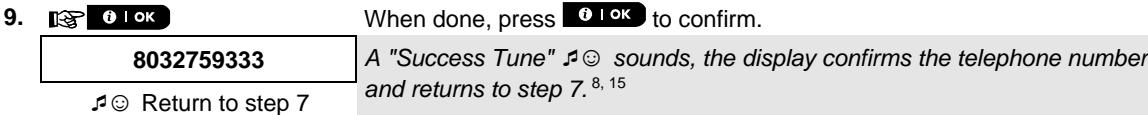
C. To Program the Number of Redial Attempts


D. To Program two-way voice communication*

Voice<- ->private


E. To Program the Acknowledge Method
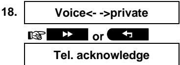
Click the or button until the display reads [Tel. acknowledge] and press OK to confirm. 12

The display shows the currently selected option.
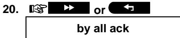
Click the or button until the display reads the desired acknowledge method, for example, "by all ack".11

A "Success Tune" sounds. The display confirms the set acknowledge method and returns to step 19.5,15
SMS REPORT
A. To Program Events to be Reported by SMS
- PRIVATE REPORT Enter the [USER SETTINGS] menu, select the [PRIVATE REPORT] option and press OK .1
- VOICE REPORT When the display reads [VOICE REPORTS] press
- SMS REPORT The display will read [SMS REPORT]. To enter this option, pres
- REPORTED EVENTS When the display reads [REPORTED EVENTS] press OK
1 OK disable report The display shows the currently selected option.
- or ← Click the → or ← button until the display reads the event group alarms you wish to be reported via SMS, for example, [alarms]. 4
- When you are satisfied with the setting, press OK to confirm.
alarms A "Success Tune" 1 sounds. The display confirms the set events to be reported, and returns to step 4.5,15
B. To Program SMS Telephone Numbers

Click the or button until the display reads the SMS phone number you wish to program or edit, for example, "2nd SMS tel#", and press OK
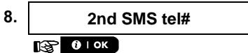
To program or edit the phone number, at the blinking cursor position enter the SMS phone number, for example, "5080168593", using the numerical keypad. 6,7
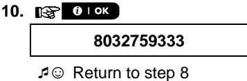
When done, press OK to confirm.
A "Success Tune" sounds, the display confirms the SMS phone number and returns to step 8.8,15
EMAIL BY SERVER
A. To Program Events to be Reported by Email via the server
- PRIVATE REPORT Enter the [USER SETTINGS] menu, select the [PRIVATE REPORT] option and press OK.
- VOICE REPORT When the display reads [VOICE REPORTS] press repeatedly until the display reads [EMAIL BY SERVER].
- EMAIL BY SERVER To enter this option, press OK . The display reads [1st E-MAIL].
1 OK
4. 1st E-MAIL Click the or button until the display reads the email you wish to program
, for example, [2nd E-MAIL] and then press OK
OK
Address
- Click the button. The display reads [E-MAIL Events].
- E-MAIL Events Press the 1ok button.
10 OK
disable report
7. or ← Click the → or ← button until the display reads the event group alarm you wish to be reported via email, for example, [alarm].13
8. ① I OK When you are satisfied with the setting, press ① I OK to confirm.
alarm A "Success Tune" sounds. The display confirms the set events to be reported, and returns to step 6. 5, 15
B. To Program Emails
- Continue from step 4 in the previous section.
- 1st E-MAIL
or
2nd E-MAIL
OK
- Address When the display reads [Address], press OK
OK
- info@visonic.com To program or edit the email, at the blinking cursor position enter the Email, for example, "info@visonic.com", using the alphanumeric keypad. 6,7
- 01ok When done, press 01ok to confirm.
info@visonic.com
Return to step 11
A "Success Tune" sounds, the display confirms the Email and returns to step 11.8,15
MMS/SMS BY SERVER
A. To Program Events to be Reported by SMS via the server
- PRIVATE REPORT Enter the [USER SETTINGS] menu, select the [PRIVATE REPORT] option and press OK .1
- VOICE REPORT When the display reads [VOICE REPORTS] press repeatedly until the display reads [SMS/MMS BY SRVR].
- SMS/MMS BY SRVR To enter this option, press OK. The display reads [1st SMS/MMS].
- 1st SMS/MMS Click the or button until the display reads the SMS phone number you wish to program, for example, [2nd SMS/MMS], and press
2nd SMS/MMS
OK
Telephone num.
- Click the button. The display reads [SMS Events].
6 SMS Events Press the OK button.
01OK
The display shows the currently selected option.
- or ← Click the → or ← button until the display reads the event group alarm you wish to be reported via SMS, for example, [alarm].13
- ① I OK When you are satisfied with the setting, press ① I OK to confirm.
alarm A "Success Tune" 4 sounds. The display confirms the set events to be reported, and returns to step 6. 5,15
B. To Program Events to be Reported by MMS via the server
- PRIVATE REPORT Enter the [USER SETTINGS] menu, select the [PRIVATE REPORT] option and press OK 1
- VOICE REPORT When the display reads [VOICE REPORTS] press repeatedly until the display reads [SMS/MMS BY SRVR].
- SMS/MMS BY SRVR To enter this option, press OK. The display reads [1st SMS/MMS].
OK
- 1st SMS/MMS Click the or button until the display reads the MMS phone number you wish to program, for example, [2nd SMS/MMS], and press OK
2nd SMS/MMS
OK
Telephone num.
- Click the button repeatedly until the display reads [MMS Events].
- MMS Events Press the OK button.
01OK
EVENT REPORTING & CONTROL BY TELEPHONE AND SMS
disable report
15.


alarm
16.


alarm
Re
turn
to s
The display shows the currently selected option.
Click the or button until the display reads the event group you wish to be reported via MMS, for example, [alarm].14
When you are satisfied with the setting, press OK to confirm.
A "Success Tune" sounds. The display confirms the set events to be reported, and returns to step 14. 5, 15
C. To Program MMS and SMS Telephone Numbers
17.
18.
1st SMS/MMS


Continue from step 4 in section A. "To Program Events to be Reported by SMS via the server"
Click the or button until the display reads the SMS/MMS telephone number you wish to program or edit, for example, "2nd SMS/MMS", and press OK.


19.
Telephone num.


20.
■895283584
When the display reads [Telephone num.], press OK
To program or edit the MMS/SMS number, at the blinking cursor position enter the MMS/SMS telephone number, for example, "895283584", using the alphanumeric keypad. 6,7
21.


When done, press OK to confirm.
A "Success Tune" sounds, the display confirms the MMS/SMS telephone number and returns to step 19.8,15
Rc
return
to step
C. To Program SMS Permission
10.


11.


12.
From Private #
Click the or button until the display reads the SMS Permission and press OK.
The display shows the currently selected setting
Click the or button until the display reads the option that you require.
When you select the 'From Any' option, SMS commands are accepted from any number.
To enter this option, press OK
When you select this option, the SMS commands are accepted only from the four numbers defined in the private SMS report.
13.


When done, press OK to confirm.
| Additional Information (section B.12) |
| 1 | For detailed instructions on how to select User Settings – refer to sections A.1 and A.2. |
| 2 | This option allows you to program the events to be reported. To program telephone numbers, click the ➔ or ➔ button until the display reads the desired option. |
| 3 | The display shows the currently selected option (indicated by a ▲ symbol), for example, "disable report". Using the ➔ or ➔ buttons you can now select the events you wish to be reported to private |
| telephones numbers according to the options provided in the tables below:PowerMaster-10 G2Event Group Option Events to be reportedalarms+ alerts Alarm and alert messagesalarms Alarm messages alerts disable report No message will be reportedPowerMaster-30 G2Event Group Option Events to be reporteddisable report No message will be reportedall All messages all (-op/cl) All messages, except arming & disarming all (-alerts) All messages, except alertsalarms Alarm messages only alerts op/cl Arming and disarming (Open/close) onlyNote: "all" means all events including the L. BAT and AC FAIL trouble messages (PowerMaster-30 G2 only). |
| 4 | The display shows the currently selected option (indicated by a ▲ symbol), for example, "disable report".Using the ▲ or ▲ buttons you can now select the events you wish to be reported to SMS numbers according to the options provided in the table below:Event Group Option Events to be reporteddisable report No message will be reportedall All messages all (-op/cl) All messages, except arming & disarming all (-alerts) All messages, except alertsalarms Alarm messages only alerts op/cl Arming and disarming (Open/close) only |
| 5 | The ▲ symbol now appears next to the new selected option. |
| 6 | a. The display shows the phone number or email currently programmed in this location (for example, 1032759641). The cursor blinks on the first digit of the code.b. If the location is free the display will be blank (---). |
| 7 | You can move the cursor to the next or previous location (digit) using the ▲ or ▲ button. |
| 8 | Within the private telephone menu, you can now repeat steps 7 - 9 to program or edit another phone number.Within the SMS menu, you can now repeat steps 8 - 10 to program or edit another SMS phone number.Within the Email menu, you can now repeat steps 10 - 13 to program or edit another email.To end this session and return to previous menu options, press the ▲ button. |
| 9 | You can select between: "1 attempt"; "2 attempts"; "3 attempts"; "4 attempts". |
| 10 | You can select between:"enable 2-way" - enables 2-way voice communication with private telephones."disable 2-way" - disables 2-way voice communication with private telephones. |
| 11 | You can select between:"by single ack" - an acknowledge signal from only a single telephone will stop the reporting process."by all ack" - an acknowledge signal from all telephones is required to stop the reporting process. |
| 12 | If the control panel is PowerMaster-10 G2 or PowerMaster-30 G2 without Voice option, the display reads "Redial attempts". |
| 13 | The display shows the currently selected option (indicated by a ▲ symbol), for example, "disable report".Using the ▲ or ▲ buttons you can now select the events you wish to be reported to emails or SMS by server according to the options provided in the table below: |
EVENT REPORTING & CONTROL BY TELEPHONE AND SMS
| Event Group Option | Events to be reported |
| disable report | No message will be reported |
| all | All messages |
| alarm | Alarm messages only |
| alarm+trbl | Alarm and trouble messages |
| alarm+o/c | Alarm messages, including arming & disarming |
| alarm+alrt | Alarm and alert messages |
| alarm+alrt+trbl | Alarm, alert and trouble messages |
| alarm+alrt+o/c | Alarm and alert messages, including arming & disarming |
| alarm+trbl+o/c | Alarm and trouble messages, including arming & disarming |
| alert | Alert messages only |
| alert+o/c | Alert messages, including arming & disarming |
| alert+o/c+trbl | Alert and trouble messages, including arming & disarming |
| alert+trbl | Alert and trouble messages |
| trouble | Trouble messages only |
| trouble+o/c | Trouble messages, including arming & disarming |
| open/close | Arming and disarming (open/close) only |
| 14 | The display shows the currently selected option (indicated by a ▲ symbol), for example, "disable report".Using the ➔ or ⇔ buttons you can now select the events you wish to be reported to MMStelephones numbers according to the options provided in the tables below: |
| Event Group Option | Events to be reported |
| alarms+alrt | Alarm and alert messages |
| alarm | Alarm messages |
| alert | Alert messages |
| disable report | No message will be reported |
| 15 | You can now, select other options, end this session – (see section A.1 and section A.2), or quitprogramming (see section A.3). |
B.13 Enabling / Disabling the Squawk Option
| The PowerMaster system (and its wireless sirens) can be set to produce a short "Squawk" of audible feedback to assist you when you use your keyfob to arm (1 beep) and disarm (2_beeps) the PowerMaster system (operates in a similar manner to a car alarm).
◆ Here you can enable / disable the Squawk. |
| ① Carefully read the section titled "Additional Information" according to the indicated references¹ etc – see table at end of this section. |
| SQUAWK | Enter the [USER SETTINGS] menu, select the [SQUAWK] option and press OK |
| Squawk on | The display shows the currently selected setting.2 |
| Squawk OFF | Click the ➔ or ← button until the display reads the desired setting, for example, "Squawk OFF" and press the OK button to confirm. |
| Squawk OFF | A "Success Tune" ⋅ sounds. The display confirms the saved setting, and then returns to the User Settings menu, step 1.3,4 |
| Return to step 1 |
| Additional Information (section B.13) |
| 1 | For detailed instructions on how to select User Settings – refer to sections A.1 and A.2. |
| 2 | a. The display shows the currently selected setting (indicated by a ▲ symbol), for example, [Squawk ON].b. You can now enable (ON) or disable (OFF) the Squawk option using the ➔ or ← button. |
EVENT REPORTING & CONTROL BY TELEPHONE AND SMS
| 3 | The ■ symbol now appears next to the new selected option. |
| 4 | You can now select another option in the User Settings menu (see section A.1 and section A.2), or quit programming (see section A.3). |
B.14 Programming the Scheduler
PGM outputs that are enrolled in the system can be used to open and close an electrically-controlled gate, or to control a preferred electrical device via keyfobs (refer to "Using keyfob transmitters" in Chapter 2) or according to a programmable weekly time schedule.
Here you can schedule the PGM output for up to 4 different ON/OFF time activations per any desired day or days of the week. In addition, you can schedule a "Daily" schedule that applies to every day of the week. It is recommended to complete the Scheduler table (placed at the end of this section) before programming the Scheduler.
Carefully read the section titled "Additional Information" according to the indicated references1 etc - see table at end of this section.
A. To Set the Scheduler
- SCHEDULER Enter the [USER SETTINGS] menu, select the [SCHEDULER] option. Press OK 1
- PGM No.-- Select the PGM number 01 to 16.Press OK
B. To Set the Day 2
Sunday
- or 2 Click the button until the display reads the day you wish to schedule or "Daily", for example, "Tuesday". 2 Tuesday
- ① I OK When the "day" to schedule appears on the display, press OK.
C. To Select the Activation No. ^3
- operation No 1 The 1^st operation (PGM output activation) of the scheduler is displayed. 3 or Click the or button until the display reads the operation you wish to schedule, for example, "operation No 3".
- 0 OK When the "operation No." to schedule appears on the display, press OK.
D. To Set the ON (Start) Time
- Start-HH:MM The "start time" screen is shown on the display. 4
1 OK To set the start time of the selected operation, press the OK button.
- TIME 10:00A The display shows the current setting of the start time. 5
TIME 12:30P
Use the numerical keypad to set or change the operation ON (start) time, for example, "00:30P".6
- 1 OK When you are satisfied with the setting, press OK to confirm.
Go to step 10 A "Success Tune" sounds. The display confirms the saved start time and returns to the "start time" screen as in step 7. To set the stop time, continue to step 10.
EVENT REPORTING & CONTROL BY TELEPHONE AND SMS
| E. To Set the OFF (Stop) Time |
| 10. | Start-HH:MM C |
| or ← |
| Stop HH:MM V |
11.


TIME
01:30P
Click the or button until the display reads "Stop-HH:MM".
When the display reads the desired setting, press OK to confirm.
The "stop time" of the selected operation is displayed.
12.
TIME
04:00P
Use the numerical keypad to set or change the operation OFF (stop) time, for example, "04:00P".6
When you are satisfied with the setting, press OK to confirm.
Return to step 5
A "Success Tune" sounds. The display confirms the saved stop time and returns to the "operation No" screen, as in step 5.
| Additional Information (section B.14) |
| 1 | For detailed instructions on how to select the Setting Options – refer to sections A.1 and A.2. |
| 2 | To activate the selected device on every day of the week at the same time(s), use the "Daily" option.
Otherwise, use the ➔ or ← buttons to select the specific day (Sunday, Monday, Tuesday...etc)
you wish to activate the PGM output. You can later repeat the process for other days of the week, if desired. |
| 3 | The display shows "operation No 1" which is the first of the 4 ON/OFF time activations you can schedule for the day selected in the previous step. You can later repeat the process for the other 3 activations on the selected day, if desired. |
| 4 | Here you can select either the "start time" or "stop time" using the ➔ or ← button. Select the time in 10 minute intervals only. To erase a displayed time, press the ☑ button.
The screen also displays the selected time format. |
| 5 | The display shows the current start or stop time setting of the selected activation with the cursor blinking on the first hour digit. If no time is programmed, the time display will be blank (- - - - ). |
| 6 | For detailed explanation of how to set the time - refer to Section B.8 B. |
| 7 | To end this session and return to the previous "operation" menu, press the ➔ button.
To select other menu options or to quit programming, follow the instructions in sections A.2 and A.3. |
Scheduler Table
| Device | Device Description | Day | Operation 1 | Operation 2 | Operation 3 | Operation 4 |
| PGM | | Monday | ON: _: _OFF: _: _ | ON: _: _OFF: _: _ | ON: _: _OFF: _: _ | ON: _: _OFF: _: _ |
| PGM | | Tuesday | ON: _: _OFF: _: _ | ON: _: _OFF: _: _ | ON: _: _OFF: _: _ | ON: _: _OFF: _: _ |
| PGM | | Wednesday | ON: _: _OFF: _: _ | ON: _: _OFF: _: _ | ON: _: _OFF: _: _ | ON: _: _OFF: _: _ |
| PGM | | Thursday | ON: _: _OFF: _: _ | ON: _: _OFF: _: _ | ON: _: _OFF: _: _ | ON: _: _OFF: _: _ |
| PGM | | Friday | ON: _: _OFF: _: _ | ON: _: _OFF: _: _ | ON: _: _OFF: _: _ | ON: _: _OFF: _: _ |
| PGM | | Saturday | ON: _: _OFF: _: _ | ON: _: _OFF: _: _ | ON: _: _OFF: _: _ | ON: _: _OFF: _: _ |
| PGM | | Sunday | ON: _: _OFF: _: _ | ON: _: _OFF: _: _ | ON: _: _OFF: _: _ | ON: _: _OFF: _: _ |
| PGM | | Daily | ON: _: _ | ON: _: _ | ON: _: _ | ON: _: _ |
EVENT REPORTING & CONTROL BY TELEPHONE AND SMS
| Device | Device Description | Day | Operation 1 | Operation 2 | Operation 3 | Operation 4 |
| | | OFF: __:__ | OFF: __:__ | OFF: __:__ | OFF: __:__ |
B.15 Volume Control
The system allows you to adjust the volume level of the various system beeps, chime signal and voice prompts, and to enable or disable status dependent, pre-recorded verbal messages (Voice option) that are heard over the built-in loudspeaker.
Here you can enable / disable the Voice option and change the volume level of the following:
Keypad beeps
Chime signal
Exit/Entry beeps
Confirmation beeps
Trouble beeps
Voice commands
Carefully read the section titled "Additional Information" according to the indicated references1 etc - see table at end of this section.
A. To Adjust the Volume Level of the Keypad Beeps
- VOLUME CONTROL Enter the [USER SETTINGS] menu, select the [VOLUME CONTROL] option and press OK.
- KP beeps vol. The display will read [KP beeps vol.]. To enter this option press OK
MID The display shows the currently selected option. 2
- or 15 Click the or button until the display reads the desired volume level for the keypad beeps, for example, [MAX].
- When you are satisfied with the setting, press OK to confirm.
MAX A "Success Tune" sounds. The display confirms the saved setting, then returns to step 2.4,7,8
Return to step 2
B. To Adjust the Volume Level of the Chime Signal
- or Click the or button until the display reads [Chime signal vol], and press OK
- Chime signal vol
OK
MID
- or 13 Click the or button until the display reads the desired volume level for the chime signal, for example, [MAX].3 MAX
- ① I OK When you are satisfied with the setting, press ② I OK to confirm. 6
MAX
Return to step 6
A "Success Tune" sounds. The display confirms the saved setting, then returns to step 6.
C. To Adjust the Volume Level of the Exit Entry Beeps
- or
Click the or button until the display reads [Exit Entry beeps], and press OK.
- Exit/Entry beeps

MID
The display shows the currently selected option. 2
- or
MAX
Click the or button until the display reads the desired volume level for the Exit/Entry beeps, for example, [MAX].3
- When you are satisfied with the setting, press OK to confirm.
MAX
A "Success Tune" sounds. The display confirms the saved setting, then returns to step 10.
Return to step 10
D. To Adjust the Volume Level of the Confirmation Beeps
- or
Click the or button until the display reads [Confirm. beep v.], and press OK.
- Confirm.beeps v.

MID
The display shows the currently selected option.
- or
MAX
Click the or button until the display reads the desired volume level for the confirmation beeps, for example, [MAX].3
- When you are satisfied with the setting, press OK to confirm.

A "Success Tune" sounds. The display confirms the saved setting, then returns to step 14.
Return to step 14
E. To Adjust the Volume Level of the Trouble Beeps
- or
Click the or button until the display reads [Trouble beeps v.], and press OK.
- Trouble beeps v.

MID
The display shows the currently selected option.
- or
MAX
Click the or button until the display reads the desired volume level for the trouble beeps, for example, [MAX].3
- 1 OK

Return to step 18
When you are satisfied with the setting, press OK to confirm.
A "Success Tune" sounds. The display confirms the saved setting, then returns to step 18.
F. To Adjust the Volume Level of the Voice Announcements
21.

Click the button until the display reads [Voice volume], and press OK.
22.


MID
23.

MAX
24.

MAX

Return to step 22
The display shows the currently selected option.
Click the button until the display reads the desired volume level for the voice announcements, for example, [MAX].3
When you are satisfied with the setting, press OK to confirm. 6
A "Success Tune" sounds. The display confirms the saved setting, then returns to step 22. 4,7,8
G. To Enable / Disable the Voice Option
25.

Click the or button until the display reads [Voice option], and press OK
26.


27.

disable prompts

disable prompts
Return to step 26
The display shows the currently selected setting.
Click the button until the display reads the desired setting, for example, "disable prompts" and press OK to confirm.
A "Success Tune" sounds. The display confirms the saved setting, then returns to step 26.
| Additional Information (section B.15) |
| 1 | For detailed instructions on how to select the Setting Options – refer to sections A.1 and A.2. |
| 2. | The display shows the currently selected setting (indicated by ■), for example, "MID ■". |
| 3 | a. Select between MAX, MID, MIN or OFF.
b. When you are selecting a level, you will hear a corresponding signal (beeps, chime, prompts, “1, 2, 3”) whose volume strength is according to the selected volume level. |
| 4 | The ▲ symbol now appears next to the newly selected option. |
| 5 | Refers to PowerMaster-30 G2 with voice option only. |
| 6 | If you have selected "enable prompts", make sure that the voice prompts can be heard over the loudspeaker by pressing the 7 key on the control panel keypad. |
| 7. | You can also adjust the volume level of the beeps or voice announcements by pressing the 1 or 4 buttons, (see Chapter 2 - Adjusting the Speech Volume and the Volume of the Keypad Beeps). |
| 8 | You can now select another option in the User Settings menu (see section A.1 and section A.2), or quit programming (see section A.3). |
B.16 Serial Number
| The SERIAL NUMBER menu enables reading the system serial number and similar data for support purposes only.
◆ Here you can read the system serial number and other relevant data. |
| ① Carefully read the section titled "Additional Information" according to the indicated references¹ etc – see table at end of this section. |
- SERIAL NUMBER Enter the [USER SETTINGS] menu, select the [SERIAL NUMBER] option and press OK.
-
090703000 Displays the control panel serial number.
-
JS702999 I19.412 Displays the PowerMaster-10 G2 panel software version. or JS702999 K19.412 Displays the PowerMaster-30 G2 panel software version.
-
JS700421 v1.0.02 Displays the control panel keypad software version. 2
-
Panel ID: 3061280924C5 Displays the control panel ID for PowerManage connectivity.
- PyTHON: Displays the GSM image transfer software version.
-
J-703002 I19.412 Displays the PowerMaster-10 G2 panel default version. or J-703002 K19.412 Displays the PowerMaster-30 G2 panel default version.
-
JS702412 K01.033 Displays the control panel boot version.
- JS702415 K02.036 Displays the control panel Remote Software Upgrade downloader version.
PL7.5.92.3 raw Displays the PowerLink software version, if installed.
- GE864-QUAD Displays the cellular modem type, if installed.
Return to step 2
3,4
| Additional Information (section B.16) |
| 1 | For detailed instructions on how to select the Setting Options – refer to sections A.1 and A.2. |
| 2 | Refers to PowerMaster-30 G2 only |
| 3 | To end this session and return to previous menu options, press the button. |
| 4 | You can now select another option in the User Settings menu (see section A.1 and section A.2), or quit programming (see section A.3). |
B.17 PowerLink Parameters*
| The PLNK curr.params menu shows the current IP address, subnet mask, default gateway and current mode of communication. The PowerLink information is for support purposes only.
◆ Here you can see the current IP address of the PowerLink and other relevant data. |
| ① Carefully read the section titled "Additional information" according to the indicated references¹ etc. - see table at end of this section. |
1.
PLNK curr.params
Enter the [USER SETTINGS] menu, select the [PLNK curr.params] option and press OK.1
2.
Curr.IP address

XXX.XXX.XXX.XXX
Displays the current PowerLink IP address.

3.
Curr.subnet mask

XXX.XXX.XXX.XXX
Displays the current PowerLink subnet mask.

4.
Current Gateway

XXX.XXX.XXX.XXX
Displays the current PowerLink default gateway.


Return to step 2
2,3
*If the Broadband Module is not registered to the PowerMaster, this menu is not displayed.
| Additional information (section B.15) |
| 1 | For detailed instructions on how to select the Setting Options – refer to sections A.1 and A.2. |
| 2 | To end this session and return to previous menu options, press the button. |
| 3 | You can now select another option in the User Settings menu (see section A.1 and section A.2), or quit programming (see section A.3). |
7. Event Reporting and Control by Telephone and SMS
Event notifications by Telephone
The PowerMaster can be programmed for selective notification of event messages to private telephone subscribers – See Chapter – 6, B.12 Programming Private Phone, Email, MMS and SMS Reporting. Messages are divided by type into the following groups:
| Group | Events Reported |
| 1 | Fire, Burglary, Panic, Tamper |
| 2* | Arming AWAY, Arming HOME, Disarming |
| 3 | No-activity, Emergency, Latchkey, Gas, Flood, Temperature |
| 4* | Low-battery AC failure |
- PowerMaster-30 G2 only
Note: For UL installations, SMS is a supplementary feature.
PowerMaster-10 G2 control panels
In case of alarm the following voice signal will be sent to private telephones upon event reporting:
- FIRE: ON - ON - ON - pause....(--- -- ...).
BURGLAR: ON continuously (——…).
* EMERGENCY: 2-tone siren; like an ambulance.
To stop the alarm notification - press the "2" key on your telephone keyboard. The alarm sound will stop immediately.
The called party must acknowledge the message (as explained later on). However, if there is no response the message will be repeated as many times as possible within a 45-second time limit. When the 45 seconds are up, the PowerMaster will disengage the line and call the next private telephone number on its list. The called party must acknowledge the message by pressing the "2" key on the telephone keypad. As a result, the PowerMaster may continue to notify the next programmed telephone number, or if so programmed, consider the event as reported - see Chapter - 6, B.11.
PowerMaster-30 G2 control panels
When the called party answers a call initiated by the PowerMaster, he will hear a verbal message composed of the "house identity" and the type of event that occurred. For example, once smoke is detected in the Smith residence, the message will be:
[The Smith Residence - Fire Alarm].
If a person under surveillance in the Watkins residence has been inactive, the message will be:
[The Watkins Residence - No Activity].
The called party must acknowledge the message (as explained later on), but if he does not respond, the message will be transmitted repeatedly as many times as possible within a 45-second time limit. When the 45 seconds are up, the PowerMaster will disengage the line and call the next private telephone number on its list.
The called party can acknowledge the message by pressing a key on the telephone keypad, as follows.
| Command | Key |
| Acknowledge only: The PowerMaster disengages the line and considers the event duly reported. | 2 |
| Acknowledge and listen-in: The protected site is “bugged” for sound for 50 seconds. The called party may prolong the listening session by pressing [3] again before the PowerMaster disengages the line, or by pressing [1] to speak. | 3 |
| Acknowledge and speak out: The called party may speak for 50 seconds to whoever is in the protected site. The called party may prolong the “speak out” session by pressing [1] again before the PowerMaster disengages the line, or by pressing [3] to listen. | 1 |
| Acknowledge and 2-way conversation: You and the called party can speak and listen without any necessity to switch the system from "listen-in" to "speak-out" and vice versa for 50 sec. (extendable). | 6 |
| Acknowledge and request a status report: The PowerMaster will issue a verbal report of system status. For example:[Disarm - ready to arm] or[Disarm - back door open] or[Disarm - alarm in memory]. | 9 |
Event notifications by SMS
Note: This feature is not to be not to be enabled in UL Listed product.
The PowerMaster system when equipped with a GSM unit can be programmed to send SMS event notification messages to 4 pre-selected telephone numbers - see Chapter - 6, B.11. The messages can be tagged with a "House ID" name, for example, "JOHN'S HOUSE", see Remote Control by SMS section, command no. 10.
Example of the reported SMS messages:
JOHN'S HOUSE
AWAY
JOHN'S HOUSE
DISARM
JOHN'S HOUSE POWERMASTER: LOW BATTERY GARAGE: LOW BATTERY
JOHN'S HOUSE STATUSMESSAGE 01 (Event list is displayed)
Note: Status messages can be sent only to a calling telephone whose identity number is not blocked by the user!
Remote Control by Telephone
Note: This feature is not to be not to be enabled in UL Listed product.
The PowerMaster allows you to initiate calls from your private telephone to the PowerMaster control panel via PSTN (landline) or GSM and to perform a variety of arming commands remotely using your telephone's keypad.
To connect to the PowerMaster when the PowerMaster is connected to the PSTN:
- Dial the PowerMaster PSTN tel. No.
- Wait for 2-4 rings then hang up.
- Wait 12-30 sec.
- Redial PowerMaster tel. No. (sound will be heard for 10 sec.).
- [^*] (to stop the sound)
- [User code], [#] 2
- [Desired command]
To connect to the PowerMaster when the PowerMaster is connected to the GSM:
- Dial the PowerMaster GSM tel. No. (sound will be heard for 10 sec.)
- [+] (to stop the sound)
- [User code], [#] 2
- [Desired command]
Notes:
(1) Entering of user code is required once only.
(2) If you wait more than 50 seconds (may change according to setup / use) without keying a command, the PowerMaster will disconnect the line.
A. Executable Commands
| Command | Single Partition Keying Sequence | All Partitions Keying Sequence |
| 1 | Disarming | [★]→[1]→[#] | [★]→[0]→[partition]→[1]→[#] |
| 2 | Arming Home | [★]→[2]→[#] | [★]→[0]→[partition]→[2]→[#] |
| 3 | Arming Home-Instant | [★]→[2]→[1]→[#] | [★]→[0]→[partition]→[2]→[1]→[#] |
| 4 | Arming Away | [★]→[3]→[#] | [★]→[0]→[partition]→[3]→[#] |
| 5 | Arming Away-Instant | [★]→[3]→[1]→[#] | [★]→[0]→[partition]→[3]→[1]→[#] |
| 6 | Arming Away-Latchkey | [★]→[4]→[#] | [★]→[0]→[partition]→[4]→[#] |
| 7 | Arming Away-Instant-Latchkey | [★]→[4]→[1]→[#] | [★]→[0]→[partition]→[4]→[1]→[#] |
EVENT REPORTING & CONTROL BY TELEPHONE AND SMS
| Command | Single Partition Keying Sequence | All Partitions Keying Sequence |
| 8 | Review status of specific partition (Voice version only)1,2 | | [★]→[0]→[partition]→[9]→[#] |
| 9 | Activating PGM output | [★]→[5]→[XX]→[1]→[#] | [★]→[5]→[device No.]→[1]→[#] |
| 10 | Deactivating PGM output | [★]→[5]→[XX]→[0]→[#] | [★]→[5]→[device No.]→[0]→[#] |
| 11 | Two-way voice communication1(see sub-par. C) | [★]→[7]→[#] | [★]→[7]→[#] |
| 12 | Recorded message playback1 | [★]→[8]→[1]→[#] | [★]→[8]→[1]→[#] |
| 13 | Recorded message start record1 | [★]→[8]→[2]→[#] | [★]→[8]→[2]→[#] |
| 14 | Recorded message stop record1 | [★]→[8]→[3]→[#] | [★]→[8]→[3]→[#] |
| 15 | Recorded message erase message1 | [★]→[8]→[4]→[#] | [★]→[8]→[4]→[#] |
| 16 | Investigating system status(Voice version only)1 | [★]→[9]→[#] | [★]→[9]→[#] |
| 17 | Quit (end communication)1 | [★]→[9]→[9]→[#] | [★]→[9]→[9]→[#] |
B. Two-Way Voice Communication
Note: This feature is not to be not to be enabled in UL Listed product.
Perform steps 1-6 in "To connect to the PowerMaster when the PowerMaster is connected to the PSTN" or steps 1-3 in "To connect to the PowerMaster when the PowerMaster is connected to the GSM" above and continue as follows:
- [★]→[7]→[#]
- Wait for 2 beeps
- [3] or [1] or [6] (see below)
The system will start to function in the "LISTEN IN" mode, letting you hear the sounds within your residence for 50 seconds. If the person under surveillance happens to speak or cry then, you will hear this. You can switch the system to Listen-In, Speak Out or Full Duplex, as shown in the next table.
| Command | Key |
| Listen-in (listening to the person at home) (*) | [3] |
| Speak-out (speaking to the person at home) (*) | [1] |
| Full-duplex (listening & speaking) (*) | [6] |
| Increase panel speaker volume | [1] |
| Decrease panel speaker volume | [4] |
Note: To prolong the communication session by 50 seconds, press [3], [1] or [6] again, as required.
- The 2-way communication can be terminated by anyone close to the PowerMaster, by disarming the system.
Listen-in & Speak-out modes allow one way speech at a time. Back and forth exchange of uninterrupted speech between two parties is a method normally used in military, commercial and amateur radio communication. Once you finish talking you should say "Go Ahead" or "Over" and then switch from speak-out to listen in. When the person at home finishes talking he should also say "Over", as a cue to you to switch back from Listen-in to speak out.
EXAMPLE:
You (at remote telephone): [1], "Hey, George, can you hear me? Are you in any trouble? Over".... [3] Person at home: "Yes, I am. I had a dizzy spell while trying to get out of bed and fell on the floor. I am unable to get up and my thigh hurts. Can you help me? Over"...
You (at remote telephone): [1], "Sure, I will send someone right away, stay put - over". [3]. Person at home: "Thanks, please hurry, over".
You (at remote telephone): [1], "All right, over and out".[★]→9]→[9] (END OF SESSION)
IMPORTANT! If you wish to exit the two-way communication mode and execute another command, just press [★] and then key your user code followed by the command (see "keying sequences" in Executable Commands table above).
Remote Control by SMS
Note: This feature is not to be not to be enabled in UL Listed product.
PowerMaster system with GSM unit can respond to SMS commands from any cellular telephone (a detailed SMS message sending process is described in the cellular telephone user's guide).
The various SMS commands are detailed in the following table.
In this table, "" means a 4-digit user code and simply means blank space (see Note).
SMS Command List
| Command | Individual Partition SMS Format | All Partitions SMS format |
| 1 | Arm AWAY | "AWAY☐<code>"or"AW☐<code>" | "P# AWAY☐<code>"or"P# AWI☐<code>" |
| 2 | Arm AWAY instant | "AWAY INST☐<code>"or"AWI☐<code>" | "P# AWAY INST☐<code>"or"P# AWI☐<code>" |
| 3 | Arm AWAYLatchkey | "LATCHKEY☐<code>"or"LK☐<code>" | "P# LATCHKEY☐<code>"or"P# LKI☐<code>" |
| 4 | Arm AWAYLatchkey instant | "LATCHKEY INST☐<code>"or"LKI☐<code>" | "P# LATCHKEY INST☐<code>"or"P# LKI☐<code>" |
| 5 | Arm HOME | "HOME☐<code>"or"HMI☐<code>" | "P# HOME☐<code>"or"P# HMI☐<code>" |
| 6 | Arm HOME instant | "HOME INST☐<code>"or"HMI☐<code>" | "P# HOME INST☐<code>"or"P# HMI☐<code>" |
| 7 | Disarm | "DISARM☐<code>"or"DA☐<code>" | "P# DISARM☐<code>"or"P# DA☐<code>" |
| 8 | Turn PGM on1 | "PGM☐XX☐ON☐<code>" | "PGM☐XX☐ON☐<code>" |
| 9 | Turn PGM off1 | "PGM☐XX☐OFF☐<code>" | "PGM☐XX☐OFF☐<code>" |
| 10 | Define customhouse identity2 | "HOUSE NAME☐<code>"or"HN☐<code>" | "P# HOUSE NAME☐<code>"or"P# HN☐<code>" |
| 11 | Query systemstatus | "STATUS☐<code>"or"ST☐<code>" | "P# STATUS☐<code>"or"P# ST☐<code>" |
Note: The PowerMaster may react with a delay to received SMS messages if a GPRS session is in progress at the same time.
8. Special Applications and Functions
Looking after People Left at Home
In addition to acting as an alarm system, the PowerMaster can also be used to monitor the movement of people at home when the system is in the disarmed state (or even when armed "HOME" with perimeter protection only), and report lack of motion in interior zones if there is no detection of motion within predetermined time limits.
To use this characteristic, you must ask your installer to program a specific time limit beyond which lack of motion will be reported as a "not active" alert. For example, let us assume that an elderly, sick or handicapped person is left unattended in a protected site. This person, disabled or sick as he may be, will not stay entirely still for hours and is expected to wander into the kitchen to eat or drink, or to the bathroom for other necessities. Upon doing so, the bedroom, bathroom and kitchen motion detectors will detect his movement.
Important!
To enable motion detectors to function during the disarmed state, all motion detectors must be configured by the installer to detect activity during disarmed state (i.e. "DISARM Activity" recommended setting ""YES + 5m delay"). For further details, refer to the motion detector's Installation Instructions.
If, for example, the "lack of motion" time limit is set by your installer to 6 hours, a virtual 6-hour clock will carry out a 6-hour "countdown".
If motion is detected within the 6-hour time frame, the countdown will restart from the beginning (the virtual 6-hour clock will be "reset") and no alert message will be sent out.
If no motion is detected within the 6-hour time frame in any interior zone, the control panel will send a "not-active" alert message to the monitoring station or to private telephones designated by the installer.
Note: Tracking inactivity of elderly (Looking after People Left at Home) not to be enabled in UL Listed product.
Acknowledging "low battery" condition in Keyfobs
Some regulations and institutions require the user to acknowledge when the keyfob enters the "low battery" condition. In such cases the installer will program the system to operate as follows:
If you try to disarm the system with a keyfob whose battery voltage is low, a protest beep will be heard for 15 seconds. During this period you should press again the disarm button of the keyfob or control panel (for the control panel, a user code is required) to disarm the system. If you perform this action during the 15 seconds period, a Low Bat acknowledge message will be stored in the event log.
If the disarm button is not pressed again during the 15 seconds period you will not be able to rearm the system unless you perform either one of the following actions:
A. Press AWAY twice to arm the system.
B. Press AWAY and then press disarm button.
Performing either of these two actions will also store the acknowledge message in the event log.
9. Testing the System
Periodic Test
The components of your security system are designed to be maintenance-free as much as possible. Nevertheless, it is mandatory to test the system at least once a week and after an alarm event to verify that all system sirens, detectors, keyfobs, keypads and other peripherals function properly. Proceed as described in this section and if there is any problem, notify your installer at once.
The test is performed in three parts:
Siren Test: Each siren of the system is automatically activated for 3 seconds (outdoor sirens with low volume). In addition, the system tests the siren of enrolled smoke sensors.
Temp/Light Test: For devices with temperature sensing, the panel displays the temperature of each zone in Celsius or Fahrenheit. For devices that have both temperature and light sensing, the panel displays the temperature and light intensity of each zone.
Other Device Test: Each of the other devices in the system is activated by the user and the display indicates which devices were not yet tested. The "it's me" indication helps to identify the untested devices if necessary. A counter also indicates the number of devices that remain untested.
Carefully read the section titled "Additional Information" according to the indicated references1 etc - see table at end of this section.
- READY 00:00


PERIODIC TEST
- 01OK
ENTERCODE:
3.CODE
Go to step 4
Make sure the system is disarmed and then press the button repeatedly until the display reads "PERIODIC TEST" and press OK. 1
B. To Test the Sirens
-
SIRENS TEST
-
1 OK

The screen will now prompt you to enter your user code.
Enter your User Code. 23
-
The display now reads [SIRENS TEST].
To initiate the siren test press OK. Immediately after pressing OK, all 5 LEDs on the panel should light (LED test).
The display now reads [SIREN N], where "N" indicates the zone location assigned to the siren that is currently being tested.
The first siren enrolled in the panel sounds for 3 seconds, after which the PowerMaster-360R system will automatically repeat the procedure for the next siren enrolled in the system until all sirens are tested.5
You should listen to the siren's sounds and make sure that all sirens sound. Once all the sirens have been tested, the control panel will then test the sirens if smoke sensors that are enrolled in the alarm system. The display now reads [Zxx: SMOKE SIREN], where "Zxx" indicates the zone number of the smoke sensor, and alternates with [ TO CONTINUE]. During this time, the siren of the tested smoke sensor will sound for up to one minute.
Press OK to test the siren of the next smoke sensor.
- SIRENS TESTS END


When the sirens test is complete, the display reads [SIREN TESTS END]. Press the OK or the button to confirm the test and then move the next step for zone temperature display.
C. To display the temperature and light intensity
TESTING THE SYSTEM
To display the temperature of zones on the control panel, press OK.
The control panel reads the temperature and light intensity of each zone. The display alternates between the temperature, the light intensity, the sensor number and the sensor location.
Repeatedly click the button to review the temperature and light intensity of each zone.
When the temperature of all zones has been reviewed, the display reads [DEVICE TESTS END]. Press the OK or the button to confirm the test and then move to the next step to test the other devices.
D. To Test all other Devices
TEST ALL DEVICES
10.

11.
NOT ACTIVE NNN

Z01 NOT ACTIVE NNN

Z01 CONTACT

FRONT DOOR
The display now reads [TEST ALL DEVICES].
To enter the devices test procedure, press OK.
The display reads [NOT ACTIVE NNN]. NNN indicates the number of enrolled devices in the panel that have not been tested yet. This number automatically drops one count for every tested device. To initiate devices test, press OK.
The display shows the 1^st device in the list of untested devices. The display alternates between the device number, the device type (e.g. magnetic contact, keyfob, keypad, etc.), and the device location.
The test is performed by activating each device as explained in point 9 in the Additional Information table below.
12.

13.
DEVICE TESTS END
READY 00:00
Click to scroll through the list of all untested devices.10
When all devices have been activated, the display reads [DEVICE TESTS END] followed by [READY 00:00].
| Additional Information (Periodic Test) |
| 1 | Display shown in disarm state when all zones are secured (00:00 or other digits show present time). |
| 2 | If you have not already changed your personal code number, use the default setting - 1111. |
| 3 | If the INSTALLER CODE is used to enter the Periodic Test instead of the USER CODE, the devices LED will also provide the link quality indication - see PowerMaster Installer's Guide. |
| 4 | To skip the SIRENS TEST and select the other devices TEST, press▶. |
| 5 | The Periodic test can be performed on a maximum of two wireless sirens and the sirens of enrolled smoke sensors. Outdoor sirens are activated with low volume. |
| 6 | The Periodic test can be performed on a maximum of two wireless sirens (including one internal siren) and the sirens of enrolled smoke sensors. Outdoor sirens are activated with low volume. |
| 7 | If no temperature sensor is enrolled in the system, the display reads "NO EXISTING DEV." |
| 8 | The displayed temperature can be in Celsius or Fahrenheit according to the programmed settings of the Temperature Sensor. |
| 9 | To activate system devices during the "Periodic Test"; make sure the device LED lights when activated:
Contact sensor: Open or close the door or window protected by the contact.
Motion sensors: Perform a "walk test" of the detector as explained in the detector's datasheet. |
| Smoke sensors: | Perform a "Diagnostic test" as explained in the detector's datasheet. |
| Keyfob: | Activate any of the keyfob buttons. |
| Keypads: | Perform a disarm or arm routine or press any other key that activates the LED. |
| Repeater: | Follow the "Diagnostic Tests" described in the repeater's datasheet. |
| Other devices: | In general, follow the "Diagnostic Tests" described in the device's datasheet or activate any of its functions. |
| 10 | a. Three seconds after the device is displayed, the device LED blinks to assist you to identify ("it's me"). |
| b. To end the session, press the ➔ button until the display reads [<OK> TO EXIT] then press ☑ I OK. |
Periodic Test per Partition
In addition to the regular Periodic Test, you can also test zones for enrolled sensors (excluding temperature sensors and sirens) that are assigned to a selected partition.
A. To Conduct the Periodic Test per Partition
- P1:R P2:N P3:- Make sure the selected partition is disarmed and the other partitions are not in exit or entry delay and then press the partition (# #) button.
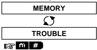
- SELECT PARTITION When the display reads [SELECT PARTITION], press the partition number of the zones you wish to test, for example, (Partition 1).
- Partition 1
- Press the >> button repeatedly until the display reads [PERIODIC TEST] and press OK.

- ENTER CODE: The screen will now prompt you to enter your Master user code.
- CODE Enter your Master user code. P1 SENSORS TEST 3
- To enter the devices test procedure per partition, press OK
- NOT ACTIVE NNN The display reads [NOT ACTIVE NNN]. NNN indicates the number of enrolled devices in the panel that have not been tested yet. This number automatically drops one count for every tested device.

After a device has been activated, the control panel reads [Zxx IS ACTIVATED] and the "N" indicator drops one count.
- Press OK. 5
Return to step 3
| Additional Information (Periodic Test per Partition) |
| 1 | Partitioning must be enabled by your installer. |
| 2 | If you have not already changed your personal code number, use the default setting – 1111. |
| 3 | To abort, press the ➔ button; the display reads [<OK> TO END]. Press the ☑ I OK button. |
| 4 | To activate system devices during the "Periodic Test Per Partition"; make sure the device LED lights when activated: |
TESTING THE SYSTEM
| Contact sensor: Open or close the door or window protected by the contact. Motion sensors: Perform a "walk test" of the detector as explained in the detector's datasheet. Smoke sensors: Perform a "Diagnostic test" as explained in the detector's datasheet. |
| 5 | Periodic test per partition will be interrupted (the panel returns to selected partition display) upon occurrence of one of the following: 1) Disarm event by keyfob, keypad or pendant assigned to a selected partition; 2) PANIC, FIRE or EMERGENCY event. |
10. Maintenance
Replacing the Backup Battery
There is generally no need to replace the battery since the battery is rechargeable. If a CPU LOW BATTERY trouble message is received when the control panel is connected to AC power and this trouble state continues for more than a few hours, the battery may need to be replaced. An original Visonic battery must be used of which there are a number of types. For assistance in battery replacement, contact Technical Support.
Replacing Wireless Devices Batteries
The wireless devices supplied with your system are powered by batteries that last several years, in normal use.
However, if and when a battery becomes weak, the device itself sends a "low battery" message to the control panel, and a low battery trouble message is displayed together with the zone information (see Chapter 5 - Correcting Trouble Situations).
The respective manuals of these sensors or devices should be consulted for proper battery replacement guidelines to be performed by the installer.
Accessing 24-Hour Zones
To access a sensor defined as a 24-hour zone without causing an alarm:
- Click - the display will read: USER SETTINGS.
- Click OK - the display will read: ENTER CODE
Key your secret 4-digit - the buzzer will play the "Success Tune" (---).
You have 4 minutes during which the 24-hour sensor can be opened and accessed. When the 4 minutes are up, the system will automatically revert to the normal mode.
Cleaning the Control Panel
The control panel may occasionally get stained if touched with greasy fingers, and may accumulate dust after a long period of use. Clean it only with a soft cloth or sponge moistened lightly with a mixture of water and mild detergent, and then wipe it dry.
The use of abrasives of any kind is strictly forbidden. Also never use solvents such as alcohol, kerosene, acetone or thinner. These will certainly ruin the external finish and damage the transparency of the top window.
Event Log
All events are memorized in an event log that contains up to 100 entries. You can access this log, review the events one by one and draw functional conclusions.
Note: Up to 250 events (PowerMaster-10 G2) / 1000 events (PowerMaster-30 G2) are stored in the event log that can be reviewed via the Remote Programmer PC software application or by the remote PowerManage server.
If the event log fills up completely, the oldest event is deleted upon registration of each new event.
The date and time of occurrence are memorized for each event. When reading the event log, events are shown in chronological order - from the newest to the oldest. The event description is shown first, then the date and time. The two displays are shown alternately several times, until you click OK to move on to an older event, or until the "no action" 4-minute timeout restores the system to the normal operating mode.
Access to the event log is provided by clicking the button and then keying your master user code. To read the event log, proceed as follows:
MAINTENANCE
READY 00:00
1.
ENTER CODE:
- CODE
LIST OF EVENTS
When the PowerMaster display reads [ENTER CODE: ], enter the current master user code.
The "Success Tune" will sound and the PowerMaster display will read [LIST OF EVENTS]. (see Important Note!)
- Click the 01ok button. The latest event will be shown.
The event is displayed in two parts, for example, "Z13 alarm" then "09/02/10 3:37 P".

09/02/10 3:37 P
The two displays will be shown alternately until clicking OK again to move to the next event or until the event log times out (4 minutes).
- Click the OK button as many times as necessary to read all the required data.
Important Note! Entering an incorrect code 3 times in a row, and after each next reentry, will initiate a 30-second penalty lockout of the keypad.
Attention: The system will not allow you to erase the event log. Only the installer is authorized to view and perform this function.
Exiting the Event Log
- or Click the button from anywhere within the event log. The PowerMaster display will read [ TO EXIT].
TO EXIT
- Click the OK button.
READY 00:00
APPENDIX A. FUNCTIONS OF CONTROLLING DEVICES
A1. KP-160 PG2
Arming and Disarming the System
| Step | Operation | User Actions | Keyboard & Panel Response |
| Optional | 1 | Select a PARTITION (if Partition is enabled) | Any combination of P2 P3 P4 | The selected key blinks. |
| 2 | Arm AWAY | + [ ] | The selected key and the "Present Prox Tag" icon ( ) begin to blink and prompt you to present your Tag. The keyprox's LED blinks red once to indicate transmission of the arming command to the control panel. The LED and the buzzer then indicate the control panel's response – see KP-160 PG2 User's Guide, "System Status and Indications" section 3.3. |
| Arm HOME | + [ ] |
| Disarm (OFF) | + [ ] |
| Optional | 3 | Quick arm AWAY (If Quick Arm is enabled) | (≈ 2 sec.) |
| Quick arm HOME (If Quick Arm is enabled) | (≈ 2 sec.) |
| Optional | 4 | INSTANT | (After arming HOME/ AWAY) [ ] |
| LATCHKEY | (After arming AWAY) [ ] |
Initiating Alarms
| Alarms | Actions | Response | Notes |
| Emergency alarm | (≈2 sec.) | See section 3.3. in KP-160 PG2 User's Guide | When pressing the Fire or Emergency icons, the KP-160 PG2 starts beeping. After pressing the button for approx. 2 seconds, the KP-160 PG2 sends the command. |
| Fire alarm | (≈2 sec.) |
| Panic alarm | (≈2 sec.) | When pressing the Fire and Emergency icons together, the KP-160 PG2 starts beeping. After pressing the button for approx. 2 seconds, the KP-160 PG2 sends the Panic command. |
Zone Status
| Alarms | Response | Notes |
| For NOT READY ( ) / BYPASSED ( ) | ⑤⑥ | Upon each press of the ☐ key, the next zone number appears on the zone # display, ☐ ☐. |
Zone Status when working with Partitions
| Alarms | Response | Notes |
| For NOT READY ( ) / BYPASSED ( ) | P1 / P2 / P3 / D | Upon each press of the ☑ key, the next zone number assigned to the pressed Partition number appears on the zone # display, ☐ ☐. |
A2. KP-140/141 PG2
Arming and Disarming the System
| Step | Basic Arming | User Actions | Keypad & Panel Response |
| 1 | Select a PARTITION (Partition enabled) | 1 or 2 or 3 | The selected button lights. |
| 2 | Arm AWAY | | The selected button starts blinking and prompts you to enter your "UserID" or present your Tag. See step 3. |
| Arm HOME | |
| Disarm (OFF) | |
| Quick arm AWAY | (≈ 2 sec.) | The keypad's LED blinks red once to indicate transmission of the arming command to the control panel. The control panel's response is then indicated on the keypad via the LED and the buzzer - see KP-140 PG2 User's Guide, "Panel Response to Keypad Commands" section 3.5 |
| Quick arm HOME | (≈ 2 sec.) |
| 3 | Enter USER CODE or present Proximity TAG. | [USER CODE] or [present TAG] |
| [DURESS CODE] (2580 by default) |
| 4 | INSTANT | (After arming HOME/ AWAY) | The keypad's LED blinks red once to indicate transmission of the command to the control panel. The control panel's response is then indicated on the keypad via the LED and the buzzer - see KP-140 PG2 User's Guide, "Panel Response to Keypad Commands" section 3.5. |
| LATCHKEY | (After arming AWAY) |
Automation
| Output Function | Actions | Response |
| PGM device ON | [XX] | The keypad's LED blinks red once to indicate transmission of the command to the control panel. The control panel's response is indicated on the keypad via the LED and the buzzer – see KP-140 PG2 User's Guide, “Panel Response to Keypad Commands” section 3.5. |
| PGM device OFF | [XX] |
| PGM device TOGGLE | [XX] |
Initiating Alarms
| Alarm | Actions | Response |
| Emergency alarm | (≈2 sec.) | See KP-140
PG2 User's Guide, “Panel Response to Keypad Commands” section 3.5 |
| Fire alarm | (≈2 sec.) |
| Panic alarm | (≈2 sec.) |
Other Functions
| Function | User Actions | Response |
| AUX Function (see Note) | * | See section 3.5 of KP-140 PG2 User's Guide. |
| STATUS indication | i | See section 3.6 of KP-140 PG2 User's Guide. |
Note: For the AUX button configuration, see the KP-140 PG2 Installation Instructions.
A3. KF-234 PG2
Keyfob Functionality
| Step | Functions | User Actions | Response |
| 1 | Arm AWAY | | When executing a command, the keyfob's LED blinks red once to indicate transmission of the command to the control panel. If the operation is successfully completed, the green LED lights momentarily and a "Success tune" is heard. If the operation fails or cannot be completed, for example, when the system is "not ready", the red LED lights steadily and a "Failure tune" is heard, see KF-234 PG2 User's Guide, "Panel Response to Keyfob Commands" section 3.2. |
| Arm HOME | |
| Disarm (OFF) | |
| 2 | LATCHKEY | |
| 3 | Panic alarm | (≈2 sec.) |
| 4 | AUX | | See section 2.2 of KF-234 PG2 User's Guide. |
APPENDIX B. PARTITIONING
The control panel includes an optional partition feature. Partitioning is available only if your installer has enabled the feature. Once partitioning is enabled Partitioning menus are added to the system which can be viewed on the control panel's LCD display. Partitioning allows you to divide the system into three independently controllable areas with different users assigned to each partition whereby each user can arm the partition to which they are assigned.
Each user code can be assigned to a combination of up to 3 partitions and each partition can be armed or disarmed regardless of the status of the other partitions within the system. For example, you can define the garage as partition 1, the basement as partition 2, and the house as partition 3. Since each partition is independent of other partitions, you can arm or disarm each partition as desired without altering the states of the other partitions.
The system also supports a situation where an area is used by two or more partitions. For example, a reception area which is common to two offices, each of which is assigned to a separate partition, will be armed only after both offices (partitions) are armed. In the armed state the reception area will be disarmed after either office (partitions) has been disarmed to allow the user of that office to use the reception area without generating an alarm. Such an area is termed a "common area".
Note: Remote operation is performed per partition, or per user code defined for a particular partition, when partition is enabled.
B1. Selecting a Partition
When operating in partition mode the first display will read:
P1: R P2: N P3: R
Press; the display will read:
SELECT PARTITION
Press 1, 2 and 3 to select the desired corresponding partition.
Note: After 5 seconds of no button press there will be a timeout and the display will revert to the All Partition display.
B2. Arming / Disarming the System
Before continuing, make sure that Partitioning has been enabled via the Installer Mode.
Arming/Disarming All Partitions
To arm/disarm all partitions in READY mode, press the button.
Arming/Disarming a Single Partition
To arm/disarm a single partition, press the # button on the control panel and then press the Partition number: 1; 2; or 3. Then, press the / button.
B3. The Show Function
The show function is enabled during single/all partition(s) status and displays information that is relevant to the selected or all partitions.
Show All Partitions
In Ready mode press OK, the display will show information on all partitions. Press OK repeatedly to view memory / status content.
Show Single Partition
In Ready mode, press # and then press the partition number. The display will show information relevant to the selected partition. Press OK repeatedly to view memory / status content.
Note: After 5 seconds of no button press there will be a timeout and the display will revert to the all partition display.
B4. Siren
A partition is alarmed when receiving an event from an alarmed device assigned to that partition. Alarmed devices do not affect partitions to which they are not assigned. A siren is common to all partitions; therefore, an alarm from one or more partitions will activate the siren.
Siren Activity
The siren will be activated when receiving an event from an alarmed device.
- Overlapping siren activations from different partitions will not cause the duration of the siren to be extended.
- When the siren sounds, it will not stop until all alarmed partitions are disarmed. However if the siren is active due to an alarm from a common area zone, and one of the partitions assigned to this area disarms the system, the siren will also stop. In case that the alarm is initiated from a common area but continues with zones that are not assigned to a common area, the siren will not stop until all partitions assigned to the alarmed zones are disarmed.
- In case that there is a fire in partition 1 and a burglary in partition 2, the siren will sound FIRE. When partition 1 is disarmed, the siren will sound BURGLAR for the remainder of the siren timeout period.
B5. Partition Status display
Partitions status is indicated in the following manner:
P1:X P2:X P3:X
Each X value indicates a different partition state, as follows:
| R | Ready |
| N | Not ready |
| A | Away |
| H | Home |
| E | Exit delay |
| D | Entry delay |
| - | Not used |
B6. Common Areas
Common areas are areas used as walkthrough zones to areas of 2 or more partitions. There may be more than one common area in an installation depending on the layout of the property. A common area is not the same as a partition; it cannot be armed / disarmed directly. Common areas are created when you assign a zone or zones to 2 or 3 partitions. Table A1 summarizes the behavior of the different zone types in a common area.
Table A1 - Common Area Definitions
| Common area zone types | Definition |
| Perimeter | ·Acts as defined only after the last assigned partition is armed AWAY or HOME.
·In case that one of the partitions is disarmed, an alarm initiated from this zone is ignored for all assigned partitions. |
| Delay zones | ·Delay zones will not trigger an entry delay unless all assigned partitions are armed. It is, therefore, not recommended to define delay zones as common areas. |
| Perimeter follower | ·Act as defined only after the last assigned partition is armed AWAY or HOME.
·In case that one of the partitions is disarmed, an alarm initiated from this zone is ignored for all assigned partitions.
·In case that one of the common area assigned partitions is in a delay state (and the other partitions are armed), the alarm will behave as a perimeter follower for this partition only. The event will be ignored for other assigned armed partitions. |
| Interior | ·Acts as defined only after the last assigned partition is armed AWAY.
·In case that one of the partitions is disarmed or armed HOME, an alarm initiated from this zone is ignored for all assigned partitions. |
| Interior follower | ·Acts as defined only after the last assigned partition is armed AWAY.
·In case that one of the partitions is disarmed or armed HOME, an alarm initiated from this zone is ignored for all assigned partitions.
·In case that one of the common area assigned partitions is in a delay state (and the other partitions are armed), the alarm will behave as an interior follower for this partition only. The event will be ignored for other assigned armed partitions. |
| Home / Delay | ·Acts as a Perimeter-Follower type when all assigned partitions are armed AWAY.
·Acts as a Delay type when at least one of the assigned partitions is armed HOME.
·Will be ignored when at least one of the assigned partitions is disarmed. |
| Emergency; Fire; Flood; Gas; Temperature; 24-hour silent; 24-hour audible; Non-alarm | ·Always armed. |
APPENDIX C. GLOSSARY
This list of terms is arranged in alphabetical order.
Abort Period: When an alarm is initiated, the internal built-in sounder is activated first for a limited period of time which is the abort period set by the installer. If you cause an alarm accidentally, you can disarm the system within the abort period before the real sirens start and before the alarm is reported to the remote responders.
Alarm: There are 2 kinds of alarm:
Loud alarm - both internal built-in and external sirens blare out constantly and the control panel reports the event by telephone or otherwise.
Silent alarm - the sirens remain silent, but the control panel reports the event by telephone or otherwise.
A state of alarm is caused by:
- Motion detected by a motion detector (when the system is in the Armed state)
- Change of state detected by a magnetic contact detector - a closed window or door is opened
- Detection of smoke by a smoke detector, detection of gas by a gas detector and detection of water based fluids by a flood detector (when in any state)
Tampering with any one of the detectors
- Pressing the two emergency buttons simultaneously on the panel's keypad.
Arming: Arming the alarm system is an action that prepares it to sound an alarm if a zone is "violated" by motion or by opening a door or window, as the case may be. The control panel may be armed in various modes (see AWAY, HOME, INSTANT and LATCHKEY).
Assigned: Refers to zones.
Associated: Refers to devices.
AWAY: This type of arming is used when the protected site is vacated entirely. All zones, interior and perimeter alike, are protected.
Bypass: Bypassed zones are zones that are not armed when arming the system. Bypassing permits arming only part of the system while allowing free movement of people within certain zones when the system is armed.
Chime Zones: Allow you to keep track of activity in the protected area while the alarm system is in the disarmed state. Whenever a chime zone is "opened", the buzzer beeps twice. The buzzer doesn't beep, however, upon closing the zone (return to normal). Residences can use this feature to annunciate visitors. Businesses can use it to signal when customers enter the premises or when personnel enter restricted areas.
Note: A 24-hour zone or a fire zone should not be designated as a chime zone, because both zone types actuate an alarm if disturbed while the system is in the disarmed state.
Although one zone or more are designated as chime zones, you can still enable or disable the chime function
using the chime ON/OFF button 8 and LED
Control Panel: The control panel is a cabinet that incorporates the electronic circuitry and microprocessor that control the alarm system. It collects information from various sensors, processes it and responds in various ways. It also includes the user-interface - control keys, numerical keypad, display, sounder and loudspeaker.
Default Settings: Settings that are applicable to a specific device group.
Detector: The device (apparatus) that sends an alarm, that communicates with the control panel (e.g. NEXT PG2 is a motion detector, SMD-426 PG2 is a smoke detector)
Disarming: The opposite of arming - an action that restores the control panel to the normal standby state. In this state, only fire and 24-hour zones will sound an alarm if violated, but an "emergency alarm" may also be initiated.
Disturbed Zone: A zone in a state of alarm (this may be caused by an open window or door or by motion in the field of view of a motion detector). A disturbed zone is considered "not secured".
Forced Arming: When any one of the system zones is disturbed (open), the alarm system cannot be armed. One way to solve this problem is to find and eliminate the cause for zone disturbance (closing doors and windows). Another way to deal with this is to impose forced arming - automatic de-activation of zones that are still disturbed upon termination of the exit delay. Bypassed zones will not be protected throughout the arming period. Even if restored to normal (closed), bypassed zones will remain unprotected until the system is disarmed.
Permission to "force arm" is given or denied by the installer while programming the system.
APPENDICES
HOME: This type of arming is used when people are present within the protected site. A classic example is night-time at home, when the family is about to retire to bed. With HOME arming, perimeter zones are protected but interior zones are not. Consequently, motion within interior zones will be ignored by the control panel, but disturbance of a perimeter zone will cause an alarm.
Instant: You can arm the system AWAY-INSTANT or HOME-INSTANT, thereby canceling the entry delay for all delay zones for the duration of one arming period.
For example, you may arm the control panel in the HOME-INSTANT mode and remain within the protected area. Only perimeter protection is active, and if you do not expect somebody to drop in while the system is armed, alarm upon entry via the main door is an advantage.
To disarm the system without causing an alarm, use your control keypad (which is normally accessible without disturbing a perimeter zone) or use a keyfob transmitter.
It's me: The PowerMaster system includes a powerful device locator that helps you to identify the actual device displayed on the LCD, as follows:
While the LCD displays a zone (device), the LED on the respective device flashes indicating "it's me". The "it's me" indication appears after a certain time delay (max. 16 seconds) and will last for as long as the LCD displays the device with a timeout of 2 minutes.
Latchkey: The Latchkey mode is a special arming mode in which designated "latchkey users" will trigger a "latchkey message" to be sent to a telephone when they disarm the system.
For example, if parents want to be sure that their child has returned from school and disarmed the system.
Latchkey arming is only possible when the system is armed in the AWAY mode.
Magnetic Contact Sensor: A Magnet-controlled switch and a wireless transmitter in a shared housing. The sensor is mounted on doors and windows to detect changes in state (from closed to open and vice versa). Upon sensing that a door or window is open, the sensor transmits an "alarm" signal to the control panel. The control panel, if not armed at that time, will consider the alarm system as "not ready for arming" until the door or window is secured and the panel receives a "restored" signal from the same sensor.
Motion Sensor: A passive Infrared motion sensor. Upon sensing motion, the sensor transmits an alarm signal to the control panel. After transmission, it stands by to sense further motion.
Non-Alarm Zone: Your installer can designate a zone for roles other than alarm. For instance, a motion sensor installed in a dark stairway may be used to switch on lights automatically when someone crosses the dark area. Another example is a miniature wireless transmitter linked to a zone that controls a gate opening mechanism.
Quick Arming: Arming without a user code. The control panel does not request your user code when you press one of the arming buttons. Permission to use this arming method is given or denied by the installer while programming the system.
Remote Responder: A responder can be either a professional service provider to which the home or business owner subscribes (a monitoring station) or a family relation/friend who agrees to look after the protected site during absence of its occupants. The control panel reports events by telephone to both kinds of responders.
Restore: When a detector reverts from the state of alarm to the normal standby state, it is said to have been "restored".
A motion detector restores automatically after detection of movement, and becomes ready to detect again. A magnetic contact detector restores only upon closure of the protected door or window.
Sensor: The sensing element: pyroelectric sensor, photo-diode, microphone, smoke optical sensor etc.
Smoke Detector, Wireless: A regular smoke detector and a wireless PowerG transceiver in a shared housing. Upon detection of smoke, the detector transmits its unique identification code accompanied by an alarm signal and various status signals to the control panel. Since the smoke detector is linked to a special fire zone, a fire alarm is initiated.
State: AWAY, HOME, AWAY-INSTANT, HOME-INSTANT, LATCHKEY, FORCED, BYPASS.
Status: AC fail, low battery, trouble, system state etc.
User Codes: The PowerMaster is designed to obey your commands, provided that they are preceded by a valid security access code. Unauthorized people do not know this code, so any attempt on their part to disarm or defeat the system is bound to fail. Some operations, however, can be carried out without a user code as they do not degrade the security level of the alarm system.
Zone: A zone is an area within the protected site under supervision of a specific detector. During programming, the installer allows the control panel to learn the detector's identity code and links it to the desired zone. Since the zone is distinguished by number and name, the control panel can report the zone status to the user and register in its memory all the events reported by the zone detector. Instant and delay zones are "on watch" only when the control panel is armed, and other (24-hour) zones are "on watch" regardless of whether the system is armed or not.
APPENDIX D. HOME FIRE ESCAPE PLANNING
Fire can spread rapidly through your home, leaving you a short time to escape safely. Your ability to get out depends on advance warning from smoke detectors and advance planning – a home fire escape plan that everyone in your family is familiar with and has practiced.
Pull together everyone in your household and make an evacuation plan.
- Draw a floor plan of your home, showing two ways out of each room, including windows. Don't forget to mark the location of every smoke detector.
Test all smoke detectors (by a qualified testing laboratory) periodically, to ensure their serviceability. Replace batteries as required.
- Make sure that everyone understands the escape plan and recognizes the sound of smoke alarm. Verify that the escape routes are clear and that doors and windows can be opened easily.
- If windows or doors in your home have security bars, make sure that the bars have quick-release mechanisms on the inside, so that they can be opened immediately in an emergency case. Quick release mechanisms won't compromise your security, but they will increase your chances of safely escaping a home fire.
- Practice the escape plan at least twice a year, making sure that everybody is involved – from kids to grandparents. Allow children to master fire escape planning and practice before holding a fire drill at night when they are sleeping. The objective is to practice, not to frighten, so telling children there will be a drill before they go to bed can be as effective as a surprise drill. If children or others do not readily waken to the sound of the smoke alarm, or if there are infants or family members with mobility limitations, make sure that someone is assigned to assist them in fire drill and in the event of an emergency.
- Agree on an outside meeting place where everyone can meet after they've escaped. Remember to get out first, and then call for help. Never go back inside until the fire department gives the OK.
- Have everyone memorize the emergency phone number of the fire department. That way any member of the household can call from a cellular phone or a neighbor's home.
- Be fully prepared for a real fire: when a smoke alarm sounds, get out immediately and once you are out, stay out - leave the firefighting to the professional!
- If you live in an apartment building, make sure that you are familiar with the building evacuation plan. In case of a fire, use the stairs, never the elevator.
Tell guests or visitors to your home about your family's fire escape plan. When visiting other people's home, ask about their escape plan. If they don't have a plan in place, offer to help them make one. This is especially important when children are permitted to attend "sleepovers" at friends' homes.
APPENDIX E. SPECIFICATIONS
E1. Functional
| PowerMaster-10 G2 | PowerMaster-30 G2 |
| Zones Number | 30 wireless zones (including 1 hard-wired input). | Up to 64 wireless zones, (including 2 hard-wired inputs). |
| Hard-wired Zone Requirements | 2.2 kΩ E.O.L. resistance (max. resistance of wires 220 Ω). | 2.2 kΩ E.O.L. resistance (max. resistance of wires 220 Ω). |
| Maximum Loop Current | 1.5 mA | 1.5 mA |
| Maximum Loop Voltage | 3.3 V | 3.3 V |
| Loop Shorted | 0.00 – 1.47 V (0.00 – 1.76 KΩ) | 0.00 – 1.47 V (0.00 – 1.76KΩ) |
| Loop Normal | 1.47 – 1.80 V (1.76-2.64 KΩ) | 1.47 – 1.80 V (1.76 – 2.64 KΩ) |
| Loop Tampered | 1.80 – 2.03 V (2.64-3.52 KΩ) | 1.80 – 2.03 V (2.64 – 3.52 KΩ) |
| Loop Alarm | 2.03 – 2.33 V (3.52-5.26 KΩ) | 2.03 – 2.33 V (3.52 – 5.26 KΩ) |
| Loop Open | 2.33 – 3.30 V (5.26 -∞ Ω) | 2.33 – 3.30 V (5.26 -∞ Ω) |
| Installer and User Codes | 1 master installer (9999 by default)*1 installer (8888 by default)*1 master user, no. 1 (1111 by default)Users nos. 2 - 8*Codes must not be identical | 1 master installer (9999 by default)*1 installer (8888 by default)*1 master user, no. 1 (1111 by default)Users nos. 2 - 48*Codes must not be identical |
| Control Facilities | -Integral keypad, wireless keyfobs and keycaps-SMS commands via optional GSM/GPRS module.Remote control by telephone.Note: For SIA CP-01 compliance, when using KF-234 PG2 an external siren must also be used. CP-01 features not to be enabled in UL Listed product. | - Integral keypad, wireless keyfobs and keycaps-SMS commands via optional GSM/GPRS module.- Remote control by telephone.Note: For SIA CP-01 compliance, when using KF-234 PG2 an external siren must also be used. CP-01 features not to be enabled in UL Listed product. |
| Display | Single line, backlit 16-large character LCD. | Single line, backlit 16-large character LCD. |
| Arming Modes | AWAY, HOME, AWAY-INSTANT, HOME-INSTANT, LATCHKEY, FORCED, BYPASS.Note: AWAY-INSTANT and HOME-INSTANT are not permissible for CP-01 installations. | AWAY, HOME, AWAY-INSTANT, HOME-INSTANT, LATCHKEY, FORCED, BYPASS.Note: AWAY-INSTANT and HOME-INSTANT are not permissible for CP-01 installations. |
| Alarm Types | Silent, personal panic/emergency, burglary, gas (CO), and fire. | Silent, personal panic/emergency, burglary, gas (CO), and fire. |
| Siren Signals | Continuous (intrusion / 24 hours / panic); triple pulse – short pause - triple pulse... (fire); four pulses – long pause – four pulses... (gas); long pulse – long pause – long pulse... (flood). | Continuous (intrusion / 24 hours / panic); triple pulse – short pause - triple pulse... (fire); four pulses – long pause – four pulses... (gas); long pulse – long pause – long pulse... (flood). |
| Siren (bell) Timeout | Programmable (4 min. by default) | Programmable (4 min. by default) |
| Internal Sounder Output | At least 85 dBA at 10 ft (3 m) | At least 85 dBA at 10 ft (3 m) |
| Supervision | Programmable time frame for inactivity alert | Programmable time frame for inactivity alert |
| Special Functions | - Chime zones-Diagnostic test and event log.- Local and Remote Programming over Telephone, GSM /GPRS connections.- Calling for help by using an emergency transmitter.- Tracking inactivity of elderly, physically handicapped and infirm people.Note: Tracking inactivity of elderly not to be enabled in UL Listed product. | - Chime zones-Diagnostic test and event log.- Local and Remote Programming over Telephone, GSM /GPRS connections.- Calling for help by using an emergency transmitter.- Tracking inactivity of elderly, physically handicapped and infirm people.- Message center (recording and playback)- Two-way voice communicationNote: Tracking inactivity of elderly not to be enabled in UL Listed product. |
| Data Retrieval | Alarm memory, trouble, event log | Alarm memory, trouble, event log |
| Real Time Clock (RTC) | The control panel keeps and displays time and date. This feature is also used for the log file by providing the date and time of each event | The control panel keeps and displays time and date. This feature is also used for the log file by providing the date and time of each event |
| Battery Test | Once every 10 seconds | Once every 10 seconds |
E2. Wireless
| PowerMaster-10 G2 | PowerMaster-30 G2 |
| RF Network | PowerG - 2-way synchronized Frequency Hopping (TDMA / FHSS) | PowerG - 2-way synchronized Frequency Hopping (TDMA / FHSS) |
| Frequency bands (MHz) | 433 - 434 | 868 - 869 | 912 - 919* | 433 - 434 | 868 - 869 | 912 - 919* |
| Maximum Tx Power | 10 dBm @ 433 MHz, 14 dBm @ 868 MHz |
| Hopping frequencies | 8 | 4 | 50 | 8 | 4 | 50 |
| Region | Worldwide | Europe | North America and selected countries | Worldwide | Europe | North America and selected countries |
| Encryption | AES-128
Note: AES-128 bit encryption for communication between control unit and initiating devices is not suitable as a means of Encrypted Line Security in UL Listed product. | AES-128
Note: AES-128 bit encryption for communication between control unit and initiating devices is not suitable as a means of Encrypted Line Security in UL Listed product. |
| Cellular Frequency (MHz) | 2G Band | 3G Band | 2G Band | 3G Band |
| 850, 900, 1800, 1900 | 850, 900, 1900, 2100 | 850, 900, 1800, 1900 | 850, 900, 1900, 2100 |
| Note: The above frequencies are dependent on country and operator. | Note: The above frequencies are dependent on country and operator. |
- For UL Listed product, enable this frequency band.
E3. Electrical
| PowerMaster-10 G2 | PowerMaster-30 G2 |
| External AC/AC adaptor | Europe: 230VAC 50Hz input, 9VAC 700mA output.
USA: 120VAC 60Hz input, 9VAC 1000mA output. | NA |
| External AC/DC adaptor | NA | External (wall-mounted) switching power supply 100VAC to 240VAC, 50/60 Hz, 0.5A / 12.5 VDC, 1.2A |
| Internal AC/DC | Internal switching power supply:
Input: 100-240VAC, 0.12 A Max.
Output: 7.5VDC, 1.2A Max. | Internal switching power supply:
Input: 100-240VAC, 0.75A
Output: 12.5 VDC, 1.6A. |
| Current Drain | Approx. 240 mA standby at the beginning (power ON) and then goes down to 90 mA standby, 1200 mA peak at full load.
The Plink module draws 200mA in quiescent condition and 350mA during communication.
The cellular modem draws 25mA in quiescent condition and 300mA during communication.
Note: When there is an AC fail, there are three PLINK options: shutdown (PLINK is turned off during AC failure), active 10 min.
(PLINK is turned off if AC failure duration is longer than 10 minutes), or active (PLINK will always be active). | Approx. 260 mA standby at the beginning (power ON) and then goes down to 60 mA., 1400 mA max. current drain during alarm. |
| Low Battery Threshold | 4.8 V | 7.2 V (6-cell battery pack)
9.6 V (8-cell battery pack) |
| Backup Battery Pack | · 4.8V 1300 mAh, rechargeable NiMH battery pack, p/n GP130AAM4YMX, manufactured by GP or p/n LTT-1300AA4Y, manufactured by LTT.
· 4.8V 1800 mAh, rechargeable NiMH battery pack, p/n GP180AAH4YMX, manufactured by GP or p/n LTT-1800AA4Y, manufactured by LTT.
· 4.8V 2200 mAh, rechargeable NiMH battery pack, p/n GP220AAH4YMX, manufactured | Backup Battery Options: |
| Backup period | Maximum external devices current (1) |
| 1300 mAh
6 Battery Pack (2) | 1800 mAh
8-Battery Pack (3) |
| 4h | 180 mA | 300 mA |
| 8h | 70 mA | 125 mA |
| 12h | 35 mA | 70 mA |
| 24h | max backup w/o load 22 | 12 mA |
| by GP or p/n LTT-2300AA4Y, manufactured by LTT. For UL Listed product, use these batteries only.
Caution! Risk of explosion if battery is replaced by an incorrect type. Dispose of used batteries according to the manufacturer's instructions.
Note: For compliance with CE standards the battery capacity must be at least 1300 mAh. | | hours | |
| 32h | no backup | 0 mA |
| 39h | no backup | no backup |
| (1) The external devices must be connected between 12V and ground. The current for each specified backup period can be drawn from the batteries with the internal GSM and the proximity reader connected to the PowerMaster-30 G2.
(2) 7.2V 1300 mAh, rechargeable NiMH battery pack, p/n 130AAM6BMX, manufactured by GP or p/n LTT-AA1300LSDX6B, manufactured by LTT.
(3) 9.6V 1800 mAh, rechargeable NiMH battery pack, p/n GP180AAH8BMX, manufactured by GP or p/n LTT-AA1800LSDX8B, manufactured by LTT.
(4) 9.6V 2200 mAh, rechargeable NiMH battery pack p/n 220AAH8BMX, manufactured by GP or p/n LTT-AA2200LSDX8B, manufactured by LTT.
Caution! Risk of explosion if battery is replaced by an incorrect type. Dispose of used batteries according to the manufacturer's instructions.
Notes:
1. For compliance with CE standards the battery backup period must be at least 12 hours.
2. For compliance with UL standards the battery backup period must be at least 24 hours.
Note: Only the LTT-AA2200LSDX8B battery pack is approved for use by UL. |
| Time to Charge | 80% (~13 Hrs) | 80% (~30 Hrs) for all battery types |
| Optional Backup Battery Pack | See "Backup Battery Options" above | See "Backup Battery Options" table above |
| Time to Charge (optional backup battery pack) | 80% (~24 Hrs) | NA |
| Wired Detectors Total (Sum) Current | NA | 36* mA max. |
| Site External Siren Current (EXT) | NA | 450* mA max @ 12.5 VDC when powered by AC/DC (10.5 VDC when in standby mode) |
| Site Internal Siren Current (INT) | NA | 450* mA max @ 12.5 VDC when powered by AC/DC (10.5 VDC when in standby mode) |
| | * Total PowerMaster-30 G2 output current (of INT & EXT sirens, PGM output and detectors) cannot exceed 550 mA. |
| PGM | Current sink to control panel GND 100 mA max.
Max. external DC voltage +30 VDC | Current sink to control panel GND 100 mA max.
Max. external DC voltage +15 VDC |
| High Current / Short Circuit Protection | NA | All outputs are protected (automatic reset fuse) |
E4. Communication
| PowerMaster-10 G2 | PowerMaster-30 G2 |
| Communication | PSTN; GSM; GPRS; IP | PSTN; GSM; GPRS; IP |
| Built-in Modem | 300 baud, Bell 103 protocol | 300 baud, Bell 103 protocol |
| Data Transfer to Local Computer | Via RS232 serial port | Via RS232 serial port |
| Report Destinations | 2 Monitoring Stations, 4 private telephones | 2 Monitoring Stations, 4 private telephones |
| Reporting Format Options | SIA, Contact ID, Scancom, SIA IP, Visonic PowerNet.
Note: For UL Listed product, the communication formats used are SIA and Contact ID. | SIA, Contact ID, Scancom, SIA IP, Visonic PowerNet.
Note: For UL Listed product, the communication formats used are SIA and Contact ID. |
| Pulse Rate | 10, 20, 33 and 40 pps - programmable | 10, 20, 33 and 40 pps - programmable |
| Message to Private Phones | Tone | Tone or voice |
| Ring Detection | The unit does not support ring detection without DC voltage present on the telephone lines. | The unit does not support ring detection without DC voltage present on the telephone lines |
E5. Physical Properties
| PowerMaster-10 G2 | PowerMaster-30 G2 |
| Operating Temp. Range | 14°F to 120°F (-10°C to 49°C)
Note: For UL Listed product, the ambient temperature is 32°F to 120°F (0°C to 49°C) | 14°F to 120°F (-10°C to 49°C)
Note: For UL Listed product, the ambient temperature is 32°F to 120°F (0°C to 49°C) |
| Storage Temp. Range | -4°F to 140°F (-20°C to 60°C) | -4°F to 140°F (-20°C to 60°C) |
| Humidity | 93% relative humidity, @ 30°C (86°F) | 93% relative humidity, @ 30°C (86°F) |
| Size | 196 x 180 x 55 mm (7-5/8 x 7 x 2 in.) | 266 x 201 x 63 mm (10-7/16 x 7-7/8 x 2-1/2 in.) |
| Weight | 658g (23 Oz) (with battery) | 1.44Kg (3.2 pounds) (with battery) |
| Color | White | White |
E6. Peripherals and Accessory Devices
| PowerMaster-10 G2 | PowerMaster-30 G2 |
| Modules | 3G / GSM (2G) GPRS, IP | 3G / GSM (2G) GPRS, IP |
| Additional wireless devices | 30 detectors, 8 keyfobs, 8 keypads, 4 sirens, 4 repeaters, 8 proximity tags | 64 detectors, 32 keyfobs, 32 keypads (10 KP-250 PG2), 8 sirens, 4 repeaters, 32 proximity tags |
| Wireless Devices and peripherals | Magnetic Contact: MC-302 PG2, MC-302E PG2, MC-302EL PG2, MC-302V PG2 Motion Detectors: Next PG2; Next K9 PG2, TOWER-20 PG2, TOWER-32AM PG2 (not UL listed), TOWER-32AM K9 PG2 (not UL listed), TOWER-30AM PG2, TOWER-30AM K9 PG2, CLIP PG2 (not UL listed), TOWER CAM PG2 PIR Camera Detectors: Next CAM PG2; Next CAM-K9 PG2 Smoke Detector: SMD-426 PG2, SMD-427 PG2 GSM Module: GSM-350 PG2 (optional) Keyfob: KF-234 PG2, KF-235 PG2 (not UL listed) Keypad: KP-140 PG2/KP-141 PG2 (with proximity tag), KP-160 PG2, KP-250 PG218 Indoor Siren: SR-720 PG2, SR-720B PG2 Outdoor Sirens: SR-730 PG2, SR-740 PG2, SR-740 HEX PG2 Repeater: RP-600 PG2 Gas: GSD-441 PG2 (not UL listed), GSD-442 PG2 Glass-break: GB-501 PG2 (not UL listed) Temperature: TMD-560 PG2 (not UL listed) Flood: FLD-550 PG2 (not UL listed), FLD-551 | Magnetic Contact: MC-302 PG2, MC-302E PG2, MC-302EL PG2, MC-302V PG2 Motion Detectors: Next PG2; Next K9 PG2, TOWER-20 PG2, TOWER-32AM PG2 (not UL listed), TOWER-32AM K9 PG2 (not UL listed), TOWER-30AM PG2, TPOWER-30AM K9 PG2, CLIP PG2 (not UL listed), TOWER CAM PG2 PIR Camera Detectors: Next CAM PG2; Next CAM-K9 PG2 Smoke Detector: SMD-426 PG2, SMD-427 PG2 GSM Module: GSM-350 PG2 (optional) Keyfob: KF-234 PG2, KF-235 PG2 (not UL listed) Keypad: KP-140 PG2/KP-141 PG2 (with proximity tag), KP-160 PG2, KP-250 PG21 Indoor Siren: SR-720 PG2, SR-720B PG2 Outdoor Sirens: SR-730 PG2, SR-740 PG2, SR-740 HEX PG2 Repeater: RP-600 PG2 Gas: GSD-441 PG2 (not UL listed), GSD-442 PG2 Glass-break: GB-501 PG2 (not UL listed) Temperature: TMDS-560 PG2 (not UL listed) Flood: FLD-550 PG2 (not UL listed), FLD-551 |
| PG2Shock: SD-304 PG2 (not UL listed)Note: UL requires that when using remote smoke/CO detectors and repeaters, each detector must be within range (STRONG) of 2 repeaters at all times (for path redundancy – UL 985). | PG2Shock: SD-304 PG2 (not UL listed)Note: UL requires that when using remote smoke/CO detectors and repeaters, each detector must be within range (STRONG) of 2 repeaters at all times (for path redundancy – UL 985). |
APPENDIX F. COMPLIANCE WITH STANDARDS

European Standards:
The PowerMaster G2 control panels are compatible with:
EN 300220, EN 301489, EN 50130-4, EN 60950-1, EN 50130-5, EN 50131-3EN 50131-6, EN 50136-1, 2,
The PowerMaster-10 Triple G2: EN 50131-4, EN 50131-10
The PowerMaster-30 G2: EN 50131-4
According to the European standard EN50131-1 and EN 50131-3, the PowerMaster G2 security grading is Grade 2 - "low to medium risk" and environmental classification is Class II - "indoor general"
According to EN 50131-6 the power supply type is A.

The PowerMaster-10 Triple G2 and PowerMaster-30 G2: ATS Category - DP4 when IP module primary SPT and GPRS- alternative SPT, according to EN50136-1 and Pass-through Operation Mode according to EN50136-2
PowerMaster-10 Triple G2: according to EN 50131-10 - Supervised Premises Transceiver (SPT) Type Z

Hereby, Visonic Ltd. declares that the radio equipment type PowerMaster-10/30 is in compliance with Directive 2014/53/EU.
The full text of the EU declaration of conformity is available at the following internet address: http://www.visonic.com/download-center.

UK standards:
This product is suitable for use in systems installed to conform to PD6662:2010 at Grade 2 and environmental class 2. DD243 and BS8243.
Applica T&C:
The PowerMaster-10 Triple G2 ATS Categories -DP4, Environmental Class II, Security Grade 2, and SPT type Z
The PowerMaster-30 G2- ATS Categories -DP4, Environmental Class II, Security Grade 2
Certified by Applica T&C in accordance with
EN 50131-1, EN 50131-3, EN 50131-6, EN 50131-5-3, EN 50130-5,
EN 50130-4, EN 50136-1, EN 50136-2
PowerMaster-10 Triple G2- EN 50131-10
Applica T&C has certified only the 868 MHz variant of this product.
U.S. Standards: PowerMaster-10 G2 and PowerMaster-30 G2
FCC-CFR 47 part 15 and part 68, UL 1023 and UL 985
Canada Standards: PowerMaster-10 G2 and PowerMaster-30 G2
IC-RSS210,ULC-C1023,ULC-S545-02
Note: Only devices operating at 912-919 MHz are tested and listed by UL/ULC.
SIA CP01 standards:
PowerMaster-10 G2 and PowerMaster-30 G2: for SIA CP01, a siren must be used in the system installation.
GSM standards:
Europe: Complies with CE standards: EN 301 511, EN301 489-7
USA: CFR 47 Part 22 (GSM850) and Part 24 (GSM 1900).
This device complies with Part 15 of the FCC Rules and with ISED license-exempt RSS standard(s). Operation is subject to the following two conditions:
(1) This device may not cause harmful interference, and (2) this device must accept any interference received, including interference that may cause undesired operation.
To comply with FCC and IC RF exposure compliance requirements, the device should be located at a distance of at least 20~cm from all persons during normal operation. The antennas used for this product must not be co-located or operated in conjunction with any other antenna or transmitter.
Note: This equipment has been tested and found to comply with the limits for a Class B digital device, pursuant to part 15 of the FCC Rules. These limits are designed to provide reasonable protection against harmful interference in a residential installation. This equipment generates uses and can radiate radio frequency energy and, if not installed and used in accordance with the instructions, may cause harmful interference to radio communications. However, there is no guarantee that interference will not occur in a particular installation. If this equipment does cause harmful interference to
WARNING! Changes or modifications to this unit not expressly approved by the party responsible for compliance could void the user's authority to operate the equipment.

W.E.E.E. Product Recycling Declaration
For information regarding the recycling of this product you must contact the company from which you originally purchased it. If you are discarding this product and not returning it for repair then you must ensure that it is returned as identified by your supplier. This product is not to be thrown away with everyday waste.
Directive 2002/96/EC Waste Electrical and Electronic Equipment.

Visonic
EMAIL:
info@visonic.com
INTERNET:
www.visonic.com
©VISONIC LTD. 2021
POWERMASTER-10/30 G2 User's Guide D-307502 Rev 2
(11/21)

D-307502