PRO9500 - Projector VIEWSONIC - Free user manual and instructions
Find the device manual for free PRO9500 VIEWSONIC in PDF.

User questions about PRO9500 VIEWSONIC
0 question about this device. Answer the ones you know or ask your own.
Ask a new question about this device
Download the instructions for your Projector in PDF format for free! Find your manual PRO9500 - VIEWSONIC and take your electronic device back in hand. On this page are published all the documents necessary for the use of your device. PRO9500 by VIEWSONIC.
USER MANUAL PRO9500 VIEWSONIC
IMPORTANT: Please read this User Guide to obtain important information on installing and using your product in a safe manner, as well as registering your product for future service. Warranty information contained in this User Guide will describe your limited coverage from ViewSonic Corporation, which is also found on our web site at http://www.viewsonic.com in English, or in specific languages using the Regional selection box in the upper right corner of our website. "Antes de operar su equipo lea cuidadosamente las instrucciones en este manual"
- User Guide
- Guide de l'utilisateur
- Bedienungsanleitung
- Guía del usuario
- Guida dell'utente
- Guia do usuário
- Användarhandbok
- Käyttöopas
- Podręcznik użytkownika
- Руководство пользователя
- 使用手册(简体)
-사용자 안내서
Compliance Information
FCC Statement
This device complies with part 15 of FCC Rules. Operation is subject to the following two conditions: (1) this device may not cause harmful interference, and (2) this device must accept any interference received, including interference that may cause undesired operation.
This equipment has been tested and found to comply with the limits for a Class B digital device, pursuant to part 15 of the FCC Rules. These limits are designed to provide reasonable protection against harmful interference in a residential installation. This equipment generates, uses, and can radiate radio frequency energy, and if not installed and used in accordance with the instructions, may cause harmful interference to radio communications. However, there is no guarantee that interference will not occur in a particular installation. If this equipment does cause harmful interference to radio or television reception, which can be determined by turning the equipment off and on, the user is encouraged to try to correct the interference by one or more of the following measures:
• Reorient or relocate the receiving antenna.
- Increase the separation between the equipment and receiver.
- Connect the equipment into an outlet on a circuit different from that to which the receiver is connected.
- Consult the dealer or an experienced radio/TV technician for help.
Warning: You are cautioned that changes or modifications not expressly approved by the party responsible for compliance could void your authority to operate the equipment.
For Canada
CE Conformity for European Countries

The device complies with the EMC Directive 2004/108/EC and Low Voltage Directive 2006/95/EC.
Following information is only for EU-member states:
The mark is in compliance with the Waste Electrical and Electronic Equipment Directive 2002/96/EC (WEEE).
The mark indicates the requirement NOT to dispose the equipment including any spent or discarded batteries or accumulators as unsorted municipal waste, but use the return and collection systems available.
If the batteries, accumulators and button cells included with this equipment, display the chemical symbol Hg, Cd, or Pb, then it means that the battery has a heavy metal content of more than 0.0005% Mercury or more than, 0.002% Cadmium, or more than 0.004% Lead.


This is a Class A product in European Union.
Warning: This is a Class A product. In a domestic environment this product may cause radio interference in which case the user may be required to take adequate measures.
Important Safety Instructions
- Read these instructions.
- Keep these instructions.
- Heed all warnings.
- Follow all instructions.
- Do not use this unit near water.
-
Clean with a soft, dry cloth.
-
Do not block any ventilation openings. Install the unit in accordance with the manufacturer's instructions.
-
Do not install near any heat sources such as radiators, heat registers, stoves, or other devices (including amplifiers) that produce heat.
-
Do not defeat the safety purpose of the polarized or grounding-type plug. A polarized plug has two blades with one wider than the other. A grounding type plug has two blades and a third grounding prong. The wide blade and the third prong are provided for your safety. If the provided plug does not fit into your outlet, consult an electrician for replacement of the obsolete outlet.
-
Protect the power cord from being walked on or pinched particularly at plugs. Convenience receptacles and the point where they exit from the unit. Be sure that the power outlet is located near the unit so that it is easily accessible.
-
Only use attachments/accessories specified by the manufacturer.
-
Use only with the cart, stand, tripod, bracket, or table specified by the manufacturer, or sold with the unit. When a cart is used, use caution when moving the cart/unit combination to avoid injury from tipping over.
-
Unplug this unit when unused for long periods of time.
-
Refer all servicing to qualified service personnel. Servicing is required when the unit has been damaged in any way, such as: if the power-supply cord or plug is damaged, if liquid is spilled onto or objects fall into the unit, if the unit is exposed to rain or moisture, or if the unit does not operate normally or has been dropped.
Declaration of RoHS Compliance
This product has been designed and manufactured in compliance with Directive 2002/95/EC of the European Parliament and the Council on restriction of the use of certain hazardous substances in electrical and electronic equipment (RoHS Directive) and is deemed to comply with the maximum concentration values issued by the European Technical Adaptation Committee (TAC) as shown below:
| Substance | Proposed Maximum Concentration | Actual Concentration |
| Lead (Pb) | 0.1% | < 0.1% |
| Mercury (Hg) | 0.1% | < 0.1% |
| Cadmium (Cd) | 0.01% | < 0.01% |
| Hexavalent Chromium ( Cr^6+ ) | 0.1% | < 0.1% |
| Polybrominated biphenyls (PBB) | 0.1% | < 0.1% |
| Polybrominated diphenyl ethers (PBDE) | 0.1% | < 0.1% |
Certain components of products as stated above are exempted under the Annex of the RoHS Directives as noted below:
Examples of exempted components are:
- Mercury in compact fluorescent lamps not exceeding 5 mg per lamp and in other lamps not specifically mentioned in the Annex of RoHS Directive.
- Lead in glass of cathode ray tubes, electronic components, fluorescent tubes, and electronic ceramic parts (e.g. piezoelectronic devices).
- Lead in high temperature type solders (i.e. lead-based alloys containing 85% by weight or more lead).
- Lead as an allotting element in steel containing up to 0.35% lead by weight, aluminium containing up to 0.4% lead by weight and as a cooper alloy containing up to 4% lead by weight.
Copyright Information
Copyright © ViewSonic® Corporation, 2010. All rights reserved.
Macintosh and Power Macintosh are registered trademarks of Apple Inc.
Microsoft, Windows, Windows NT, and the Windows logo are registered trademarks of Microsoft Corporation in the United States and other countries.
ViewSonic, the three birds logo, OnView, ViewMatch, and ViewMeter are registered trademarks of ViewSonic Corporation.
VESA is a registered trademark of the Video Electronics Standards Association. DPMS and DDC are trademarks of VESA.
PS/2, VGA and XGA are registered trademarks of International Business Machines Corporation.
Disclaimer: ViewSonic Corporation shall not be liable for technical or editorial errors or omissions contained herein; nor for incidental or consequential damages resulting from furnishing this material, or the performance or use of this product.
In the interest of continuing product improvement, ViewSonic Corporation reserves the right to change product specifications without notice. Information in this document may change without notice.
No part of this document may be copied, reproduced, or transmitted by any means, for any purpose without prior written permission from ViewSonic Corporation.
Product Registration
To meet your future needs, and to receive any additional product information as it becomes available, please register your product on the Internet at: www.viewsonic.com. The ViewSonic® Wizard CD-ROM also provides an opportunity for you to print the registration form, which you may mail or fax to ViewSonic.
For Your Records
Product Name:
Pro9500
Model Number:
ViewSonic LCD Projector
VS13835
Document Number:
Pro9500_UG_ENG Rev. 1A 11-02-10
Serial Number:
Purchase Date:
Personal Identification Number (PIN):
Product disposal at end of product life
The lamp in this product contains mercury which can be dangerous to you and the environment. Please use care and dispose of in accordance with local, state or federal laws.
ViewSonic respects the environment and is committed to working and living green. Thank you for being part of Smarter, Greener Computing. Please visit ViewSonic website to learn more.
USA & Canada: http://www.viewsonic.com/company/green/recycle-program/
Europe: http://www.viewsoniceurope.com/uk/support/recycling-information/
Taiwan: http://recycle.epa.gov.tw/recycle/index2.aspx
Projector
Pro9500
User's Manual (detailed)
Operating Guide

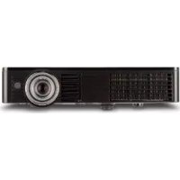
natural_image
Line drawing of a projector with visible screen and ventilation grille (no text or symbols)About this manual
Various symbols are used in this manual. The meanings of these symbols are described below.
WARNING
This symbol indicates information that, if ignored, could possibly result in personal injury or even death due to incorrect handling.
CAUTION
This symbol indicates information that, if ignored, could possibly result in personal injury or physical damage due to incorrect handling.
NOTICE
This entry notices of fear of causing trouble.
Please refer to the pages written following this symbol.
NOTE • The information in this manual is subject to change without notice.
- The manufacturer assumes no responsibility for any errors that may appear in this manual.
- The reproduction, transfer or copy of all or any part of this document is not permitted without express written consent.
Trademark acknowledgment
- Mac ^ is a registered trademark of Apple Inc.
- Windows ^ , DirectDraw ^ and Direct3D ^ are registered trademarks of Microsoft Corporation in the U.S. and/or other countries.
• VESA and DDC are trademarks of the Video Electronics Standard Association. - HDMI, the HDMI logo, and High-Definition Multimedia Interface are trademarks or registered trademarks of HDMI Licensing LLC in the United States and other countries.
- Trademark PJLink is a trademark applied for trademark rights in Japan, the United States of America and other countries and areas.
- Blu-ray Disc is a trademark.
All other trademarks are the properties of their respective owners.

Contents
Introduction 6
Features......6
Checking the contents of package....6
Part names....7
Setting up....8
Arrangement 8
Connecting with your devices 9
Connecting to a power supply.... 18
Using the security bar and slot.... 18
Remote control 19
Installing the batteries.... 19
About the remote control signal 19
Changing the frequency of remote control signal 20
Using as a simple PC mouse & keyboard.... 20
Power on/off 21
Turning on the power 21
Turning off the power 21
Operating 22
Adjusting the volume.... 22
Temporarily muting the sound.... 22
Selecting an input signal 22
Searching an input signal.... 24
Selecting an aspect ratio.... 24
Adjusting the projector's elevator 25
Adjusting the lens.... 26
Using the automatic adjustment feature.... 27
Adjusting the position.... 27
Correcting the distortion 28
Using the magnify feature 29
Temporarily freezing the screen.... 31
Temporarily blanking the screen 31
Using the menu function 32
EASY MENU....34
ASPECT, AUTO KEYSTONE, KEYSTONE, KEYSTONE, PERFECT FIT, PICTURE MODE, ECO MODE, MIRROR, RESET, FILTER TIME, LANGUAGE, ADVANCED MENU, EXIT
PICTURE menu....36
BRIGHTNESS, CONTRAST, GAMMA, COLOR TEMP, COLOR, TINT, SHARPNESS, ACTIVE IRIS, MY MEMORY
IMAGE menu....39
ASPECT, OVER SCAN, V POSITION, H POSITION, H PHASE, H SIZE, AUTO ADJUST EXECUTE
INPUT menu 42
PROGRESSIVE, VIDEO NR, COLOR SPACE, COMPONENT, VIDEO FORMAT, HDMI FORMAT, HDMI RANGE, COMPUTER IN, FRAME LOCK, RESOLUTION
SETUP menu 46
AUTO KEYSTONE, KEYSTONE, KEYSTONE, PERFECT FIT, AUTO ECO MODE, ECO MODE, MIRROR, STANDBY MODE, MONITOR OUT
Contents
AUDIO menu....49
VOLUME, SPEAKER, AUDIO SOURCE, HDMI AUDIO, MIC LEVEL, MIC VOLUME
SCREEN menu....51
LANGUAGE, MENU POSITION, BLANK, START UP, MyScreen, MyScreen Lock, MESSAGE, SOURCE NAME, TEMPLATE, C.C.
OPTION menu....57
AUTO SEARCH, AUTO KEYSTONE, DIRECT POWER ON, AUTO POWER OFF, USB TYPE B, LAMP TIME, FILTER TIME, MY BUTTON, MY SOURCE, SERVICE
NETWORK menu 67
SETUP, PROJECTOR NAME, MY IMAGE, AMX D.D., PRESENTATION, INFORMATION, SERVICE
SECURITY menu 74
SECURITY PASSWORD CHANGE, MYSCREEN PASSWORD, PIN LOCK, TRANSITION DETECTOR, MY TEXT PASSWORD, MY TEXT DISPLAY, MY TEXT WRITING, SECURITY INDICATOR, STACK LOCK
Presentation tools 80
PC-LESS Presentation 80
Thumbnail Mode, Full Screen Mode, Slideshow mode, Playlist
USB Display....89
Right-Click menu, Floating menu, Options window
Maintenance 92
Replacing the lamp 92
Cleaning and replacing the air filter 94
Replacing the internal clock battery 96
Other care 97
Troubleshooting....98
Related messages 98
Regarding the indicator lamps 99
Shutting the projector down 101
Resetting all settings.... 101
Phenomena that may be easy to be mistaken for machine defects.... 102
Specifications 106
Network Guide
1. Connection to the Network 108
1.1 System requirements 108
1.1.1 Required equipment preparation 108
1.1.2 Hardware and software requirement for computer 108
1.2 Installing the "LiveViewer" 110
1.2.1 Installing the "LiveViewer" 110
1.3 Process to connect the network 112
1.3.1 Process overview 112
1.3.2 Starting the "LiveViewer" 113
1.4 Selecting the network connection mode 114
1.4.1 Selecting either the wireless LAN or wired LAN 114
1.4.2 Selecting My Connection 116
1.5 Selecting the network connection method 116
1.5.1 Passcode connection 117
1.6 Manual Configuration 127
1.6.1 Profile connection 127
1.6.2 History connection 128
1.7 Configuring the network settings manually 129
1.8 Confirming the connection to your destination 134
1.8.1 Connection and transmission 134
1.8.2 Connection error 136
1.9 Profile data 137
1.9.1 Outline of Profile data 137
1.9.2 Making Profile data 137
1.9.3 Editing Profile data 138
1.9.4 Registering My Connection 139
2. Network Presentation ...... 141
2.1 Using the "LiveViewer" 141
2.1.1 Main menu and Operating buttons 141
2.1.2 Displaying the status 143
2.1.3 Switching the display mode 144
2.1.4 Option menu 145
2.2 Starting the Network Presentation 147
2.2.1 Display mode 147
2.2.2 Presenter mode 148
2.2.3 Display User Name 148
3. Web Control 149
3.1 Logon 150
3.2 Network Information 152
3.3 Network Settings 153
3.4 Port Settings 154
3.5 Mail Settings 156
3.6 Alert Settings 157
3.7 Schedule Settings 158
3.8 Date/Time Settings 162
3.9 Security Settings 164
3.10 Projector Control 165
3.11 Remote Control 171
3.12 Projector Status 172
3.13 Network Restart 173
4. My Image Function 174
5. Messeger Function 176
6. Network Bridge Function 178
6.1 Connecting devices 178
6.2 Communication setup 179
6.3 Communication port 179
6.4 Transmission method 180
6.4.1 HALF-DUPLEX 180
6.4.2 FULL-DUPLEX 181
7. Other Functions ...... 182
7.1 E-mail Alerts 182
7.2 Projector Management using SNMP 184
7.3 Event Scheduling 184
7.4 Command Control via the Network 188
8. Troubleshooting 193
Appendix 196
RS232 196
PJLink....219
Instant Stack Guide 221
End User License Agreement for the projector software 258
Introduction
Features
The projector provides you with the broad use by the following features.
√ This projector has a variety of I/O ports that supposedly cover for any business scene. The HDMI port can support various image equipment which have digital interface to get clearer pictures on a screen.
√ This projector has a 1.7 times optical zoom, horizontal and vertical manual lens shift, allowing flexible installation.
√ If you insert a USB storage device, such as a USB memory, into the USB TYPE A port and select the port as the input source, you can view images stored in the device.
√ This projector can be controlled and monitored via LAN connection.
√ The built-in 16W speaker can deliver sufficient sound volume in a large space like a classroom without external speakers.
Contents of package
Your projector should come with the items shown below. Check that all the items are included. Require of your dealer immediately if any items are missing.
(1) Remote control with two AA batteries
(2) Power cord
(3) Computer cable
(4) Lens cover
(5) User's manuals (Book x1, CD x1)
(1)
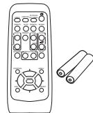
natural_image
Line drawing of a remote control with two rolled-up scrolls beside it (no text or symbols)(4)

(2)

(5)

(3)

NOTE • Keep the original packing materials for future reshipment. Be sure to use the original packing materials when moving the projector. Use special caution for the lens.
- The projector may make a rattling sound when tilted, moved or shaken, since a flap to control the air flow inside of the projector has moved. Be aware that this is not a failure or malfunction.
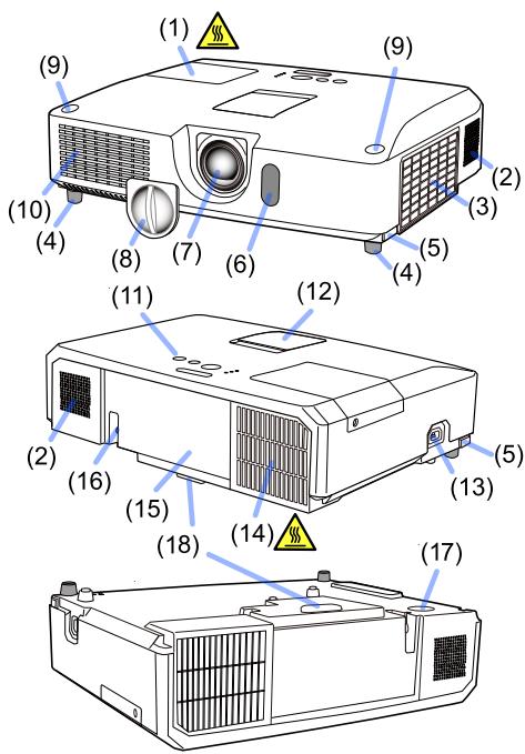
Part names
Projector
(1) Lamp cover
The lamp unit is inside.
(2) Speakers (x2)
(3) Filter cover
The air filter and intake vent are inside.
(4) Elevator feet (x2)
(5) Elevator buttons (x2)
(6) Remote sensor
(7) Lens
(8) Lens cover
(9) Pocket caps
(10) Intake vents
(11) Control panel
(12) Lens adjuster door
The adjusters for the lens are behind the door.
(13) AC IN (AC inlet)
(14) Exhaust vent
(15) Rear panel
(16) Security bar
(17) Battery cover
The internal clock battery is inside.
(18) Heel

⚠ WARNING ▶ Do not open or remove any portion of the product, unless the manuals direct it.
▶ Do not subject the projector to unstable conditions.
▶ Do not apply a shock or pressure to this product.
▶ Do not look into the lens and the openings on the projector while the lamp is on.
▶ Keep the pocket caps away from children and pets. Make sure they do not swallow the caps. If swallowed consult a physician immediately for emergency treatment.
⚠ CAUTION ▶ Do not touch around the lamp cover and the exhaust vents during use or just after use, since it is too hot.
▶ Do not attach anything onto the lens except the lens cover of this projector because it could damage the lens, such as melting the lens.
(continued on next page)
Part names (continued)
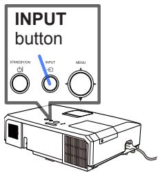
Control panel and Lens adjusters
(1) Lens adjuster door
(2) FOCUS ring
(3) ZOOM ring
(4) HORIZONTAL (horizontal) adjuster
(5) VERTICAL (vertical) adjuster
(6) LOCK (horizontal lens position lock)
(7) STANDBY/ON button
(8) INPUT button
(9) MENU button
(10) SECURITY indicator
(11) LAMP indicator
(12) TEMP indicator
(13) POWER indicator
(14) Cap storage pockets
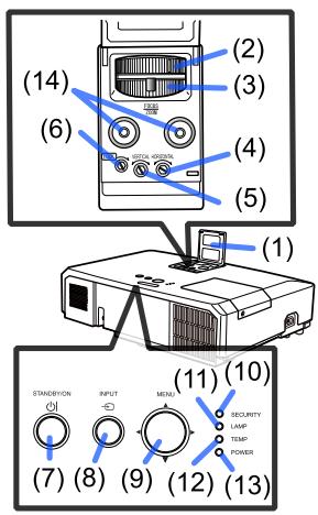
text_image
(14) (2) (3) (4) (5) (6) (1) STANDARD INPUT MEAL SECURITY LAMP TEMP POWER (7) (8) (9) (10) (11) (12) (13)Rear panel
(1) LAN port
(2) USB TYPE A port
(3) HDMI port
(4) USB TYPE B port
(5) MIC port
(6) AUDIO IN1 port
(7) AUDIO IN2 port
(8) AUDIO IN3 (R,L) ports
(9) AUDIO OUT (R,L) ports
(10) COMPUTER IN1 port
(11) COMPUTER IN2 ports
(G/Y, B/Cb/Pb, R/Cr/Pr, H, V)
(12) REMOTE CONTROL port
(13) MONITOR OUT port
(14) CONTROL port
(15) COMPONENT ports (Y,Cb/Pb, Cr/Pr)
(16) VIDEO port
(17) S-VIDEO ports
(18) Shutdown switch
(19) Security slot
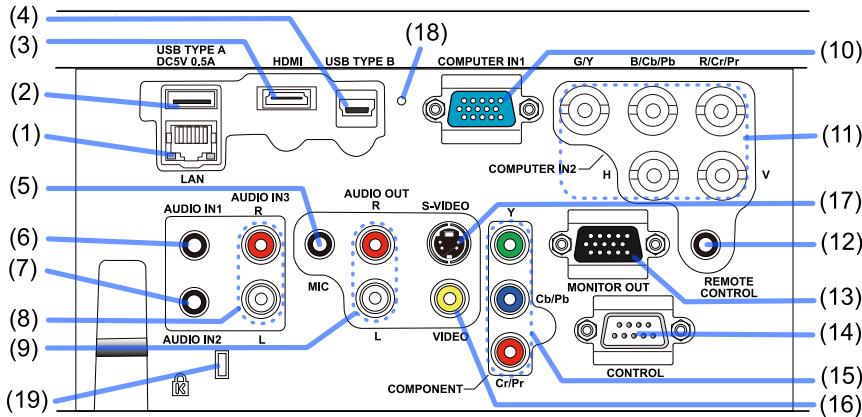
text_image
(4) (3) USB TYPE A DC5V 0.5A HDMI USB TYPE B COMPUTER IN1 G/Y B/Cb/Pb R/Cr/Pr (18) (2) (1) LAN COMPUTER IN2 H v (5) AUDIO IN1 AUDIO IN3 S-VIDEO Y MONITOR OUT REMOTE (6) R MIC L L VIDEO Crb/Pb CONTROL (7) (8) AUDIO IN2 L VIDEO COMPONENT (9) (10) (11) (12) (13) (14) (15) (16)(continued on next page)
ViewSonic
Part names (continued)
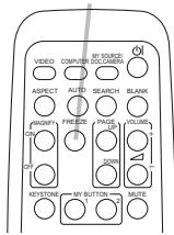
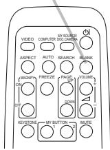
Remote control
(1) VIDEO button
(2) COMPUTER button
(3) SEARCH button
(4) STANDBY/ON button
(5) ASPECT button
(6) AUTO button
(7) BLANK button
(8) MAGNIFY - ON button
(9) MAGNIFY - OFF button
(10) MY SOURCE/DOC.CAMERA button
(11) VOLUME - button
(12) PAGE UP button
(13) PAGE DOWN button
(14) VOLUME + button
(15) MUTE button
(16) FREEZE button
(17) MY BUTTON - 1 button
(18) MY BUTTON - 2 button
(19) KEYSTONE button
(20) POSITION button
(21) MENU button
(22) ▲/▼/◄/► cursor buttons
(23) ENTER button
(24) ESC button
(25) RESET button
(26) Battery cover

natural_image
Line drawing of a remote control casing with a labeled component (26), no text or symbols present.Back of the remote control
Setting up
Install the projector according to the environment and manner the projector will be used in.
For the case of installation in a special state such as ceiling mount, the specified mounting accessories and service may be required.
Before installing the projector, consult your dealer about your installation.

natural_image
Interior view of a room with two lighting fixtures and a battery, no text or symbols visibleArrangement
Refer to the following tables T-1 to determine the screen size and projection distance. The values shown in the table are calculated for a full size screen.
(H) × (V) : Screen size
① : Projection distance (from the projector's end)
⑥, ⑤: Screen height

text_image
H V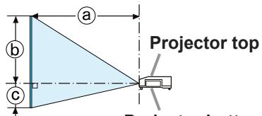
text_image
a b c Projector topProjector bottom
T-1
(1024X768) (±10%)
| Screen type | 4:3 | 16:9 | |||||||||||||||||
| Screen size | Projection distance | Screen height | Screen size | Projection distance | Screen height | ||||||||||||||
| H | V | a min. | a max. | b | c | H | V | a min. | a max. | b | c | ||||||||
| (inch) | m | m | m | inch | m | inch | cm | inch | cm | inch | m | m | m | inch | m | inch | cm | inch | cm |
| 30 | 0.6 | 0.5 | 0.9 | 34 | 1.5 | 57 | 46 | 18 | 0 | 0 | 0.7 | 0.4 | 0.9 | 37 | 1.6 | 63 | 44 | 17 | -6 |
| 40 | 0.8 | 0.6 | 1.2 | 46 | 2.0 | 77 | 61 | 24 | 0 | 0 | 0.9 | 0.5 | 1.3 | 50 | 2.1 | 84 | 58 | 23 | -8 |
| 50 | 1.0 | 0.8 | 1.5 | 58 | 2.5 | 97 | 76 | 30 | 0 | 0 | 1.1 | 0.6 | 1.6 | 63 | 2.7 | 106 | 73 | 29 | -10 |
| 60 | 1.2 | 0.9 | 1.8 | 70 | 3.0 | 117 | 91 | 36 | 0 | 0 | 1.3 | 0.7 | 1.9 | 76 | 3.2 | 128 | 87 | 34 | -12 |
| 70 | 1.4 | 1.1 | 2.1 | 82 | 3.5 | 137 | 107 | 42 | 0 | 0 | 1.5 | 0.9 | 2.3 | 90 | 3.8 | 150 | 102 | 40 | -15 |
| 80 | 1.6 | 1.2 | 2.4 | 94 | 4.0 | 157 | 122 | 48 | 0 | 0 | 1.8 | 1.0 | 2.6 | 103 | 4.3 | 171 | 116 | 46 | -17 |
| 90 | 1.8 | 1.4 | 2.7 | 106 | 4.5 | 177 | 137 | 54 | 0 | 0 | 2.0 | 1.1 | 2.9 | 116 | 4.9 | 193 | 131 | 51 | -19 |
| 100 | 2.0 | 1.5 | 3.0 | 118 | 5.0 | 197 | 152 | 60 | 0 | 0 | 2.2 | 1.2 | 3.3 | 129 | 5.5 | 215 | 145 | 57 | -21 |
| 120 | 2.4 | 1.8 | 3.6 | 142 | 6.0 | 237 | 183 | 72 | 0 | 0 | 2.7 | 1.5 | 3.9 | 155 | 6.6 | 258 | 174 | 69 | -25 |
| 150 | 3.0 | 2.3 | 4.5 | 179 | 7.5 | 297 | 229 | 90 | 0 | 0 | 3.3 | 1.9 | 5.0 | 195 | 8.2 | 323 | 218 | 86 | -31 |
| 200 | 4.1 | 3.0 | 6.1 | 239 | 10.1 | 396 | 305 | 120 | 0 | 0 | 4.4 | 2.5 | 6.6 | 261 | 11.0 | 432 | 291 | 114 | -42 |
| 250 | 5.1 | 3.8 | 7.6 | 300 | 12.6 | 496 | 381 | 150 | 0 | 0 | 5.5 | 3.1 | 8.3 | 327 | 13.7 | 541 | 363 | 143 | -52 |
| 300 | 6.1 | 4.6 | 9.1 | 360 | 15.1 | 596 | 457 | 180 | 0 | 0 | 6.6 | 3.7 | 10.0 | 393 | 16.5 | 650 | 436 | 172 | -62 |
Arrangement (continued)
⚠ WARNING ▶ Install the projector where you can access the power outlet easily. If an abnormality should occur, unplug the projector urgently. Otherwise it could cause a fire or electric shock.
▶ Do not subject the projector to unstable conditions. If the projector falls or topples over, it could result in injury or damage to the projector and the surrounding things. Using a damaged projector could result in a fire and an electric shock.
- Do not place the projector in unstable places, such as an inclined surface, places subject to vibration, on top of a wobbly table or cart, or a surface that is smaller than the projector.
- Do not put the projector on its side, front or rear position.
- Do not attach nor place anything on the projector unless otherwise specified in the manual.
- Do not use any mounting accessories except the accessories specified by the manufacturer. Read and keep the manuals of the accessories used.
- For special installation such as ceiling mounting, be sure to consult your dealer beforehand.
▶Do not install the projector near thermally conductive or flammable things. Such things when heated by the projector could result in a fire and burns.
- Do not place the projector on a metal stand.
▶ Do not place the projector where any oils, such as cooking or machine oil, are used. Oil may harm the product, resulting in malfunction, or falling from the mounted position.
▶ Do not place the projector in a place where it may get wet. Getting the projector wet or inserting liquid into the projector could cause a fire and an electric shock, and damage the projector.
- Do not place the projector near water, such as in a bathroom, kitchen, or poolside.
- Do not place the projector outdoors or by the window.
- Do not place anything containing liquid near the projector.
(continued on next page)
Arrangement (continued)
⚠️ CAUTION ▶ Place the projector in a cool place with sufficient
ventilation. The projector may shutdown automatically or may malfunction if its internal temperature is too high.
Using a damaged projector could result in a fire and an electric shock.
- Do not place the projector in direct sunlight or near hot objects such as heaters.
- Keep a space of 30 cm or more between a side of the projector and other objects such as walls.
- Do not place the projector on carpet, cushions or bedding.
- Do not stop up, block nor cover the projector's vent holes. Do not place anything around the projector that could be sucked in or stuck to the projector's intake vents.
- Do not place the projector at places that are exposed to magnetic fields, doing so can cause the cooling fans inside the projector to malfunction.
▶ Avoid placing the projector in smoky, humid or dusty place. Placing the projector in such places could cause a fire, an electric shock and malfunction of the projector.
- Do not place the projector near humidifiers. Especially for an ultrasonic humidifier, chlorine and minerals contained in tap water are atomized and could be deposited in the projector causing image degradation or other problems.
- Do not place the projector in a smoking area, kitchen, passageway or by the window.
NOTICE • Position the projector to prevent light from directly hitting the projector's remote sensor.
- Do not place the product in a place where radio interference may be caused.
- Check and correct the setting for FAN SPEED of SERVICE in the OPTION menu according to the usage environment. If the projector is used with a wrong setting, it may cause damage to the projector itself or the parts inside.
- Keep heat-sensitive things away from the projector. Otherwise, they may be damaged by the heat from the projector.
Connecting with your devices
Before connecting the projector to a device, consult the manual of the device to confirm that the device is suitable for connecting with this projector and prepare the required accessories, such as a cable in accord with the signal of the device. Consult your dealer when the required accessory did not come with the product or the accessory is damaged.
After making sure that the projector and the devices are turned off, perform the connection, according to the following instructions. Refer to the figures in subsequent pages.
Before connecting the projector to a network system, be sure to read Network Guide too.
⚠ WARNING ▶ Use only the appropriate accessories. Otherwise it could cause a fire or damage the projector and devices.
- Use only the accessories specified or recommended by the projector's manufacturer. It may be regulated under some standard.
- Neither disassemble nor modify the projector and the accessories.
- Do not use the damaged accessory. Be careful not to damage the accessories. Route a cable so that it is neither stepped on nor pinched out.
⚠️ CAUTION ▶ For a cable with a core at only one end, connect the end with the core to the projector. That may be required by EMI regulations.
NOTE • Do not turn on or off the projector while connected to a device in operation, unless that is directed in the manual of the device. Otherwise it may cause malfunction in the device or projector.
- The function of some input ports can be selected according to your usage requirements. Check the reference page indicated beside each port in the following illustration.
- Be careful not to mistakenly connect a connector to a wrong port. Otherwise it may cause malfunction in the device or projector.
- When connecting a connector to a port, make sure that the shape of the connector fits the port.
- Tighten the screws to connect a connector equipped with screws to a port.
- Use the cables with straight plugs, not L-shaped ones, as the input ports of the projector are recessed.
About Plug-and-Play capability
- Plug-and-Play is a system composed of a computer, its operating system and peripheral equipment (i.e. display devices). This projector is VESA DDC 2B compatible. Plug-and-Play can be used by connecting this projector to a computer that is VESA DDC (display data channel) compatible.
- Take advantage of this feature by connecting a computer cable to the COMPUTER IN1 port (DDC 2B compatible). Plug-and-Play may not work properly if any other type of connection is attempted.
- Please use the standard drivers in your computer as this projector is a Plug-and-Play monitor.
Connecting with your devices (continued)
Computer
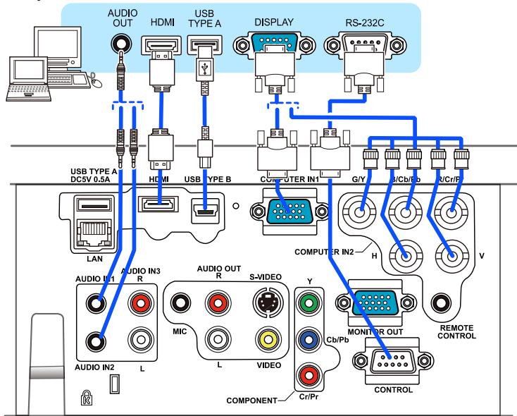
flowchart
graph TD
    A["Computer"] --> B["USB TYPE A DCSV 0.5A"]
    A --> C["USB TYPE B"]
    A --> D["COMPUTER IN1"]
    A --> E["COMPUTER IN2"]
    A --> F["MONITOR OUT"]
    A --> G["CONTROL"]
    A --> H["REMOTE CONTROL"]
    A --> I["COMPONENT"]
    A --> J["S-VIDEO"]
    A --> K["AUDIO OUT R"]
    A --> L["AUDIO IN3 R"]
    A --> M["AUDIO IN2 L"]
    A --> N["AUDIO OUT H"]
    A --> O["AUDIO IN2 V"]
    A --> P["RS-232C"]
NOTE • Before connecting the projector to a computer, consult the computer's manual and check the compatibility of the signal level, the synchronization methods and the display resolution output to the projector.
- Some signal may need an adapter to input this projector.
- Some computers have multiple screen display modes that may include some signals which are not supported by this projector.
- Although the projector can display signals with resolution up to UXGA (1600X1200), the signal will be converted to the projector's panel resolution before being displayed. The best display performance will be achieved if the resolutions of the input signal and the projector panel are identical.
- If you connect this projector and a notebook computer, you need output the display to an external monitor, or output simultaneously to the internal display and an external monitor. Consult the computer's manual for the setting.
- Depending on the input signal, the automatic adjustment function of this projector may take some time and not function correctly.
- Note that a composite sync signal or sync-on-green signal may confuse the automatic adjustment function of this projector.
- If the automatic adjustment function does not work correctly, you may not see the dialog to set the display resolution. In such a case, use an external display device. You may be able to see the dialog and set an appropriate display resolution.
(continued on next page)
Connecting with your devices (continued)
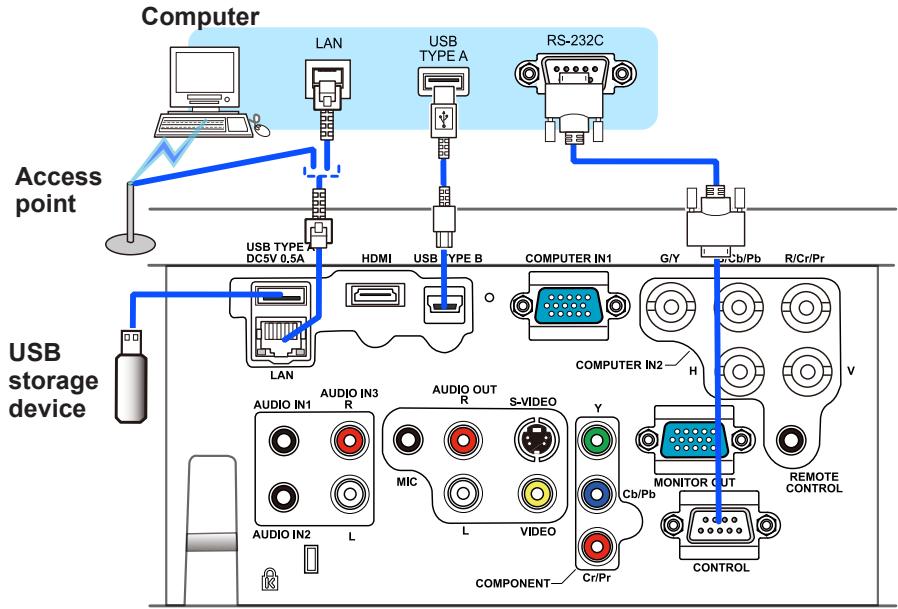
flowchart
graph TD
    A["Computer"] --> B["LAN"]
    B --> C["USB TYPE A"]
    B --> D["RS-232C"]
    C --> E["USB TYPE B"]
    D --> F["COMPUTER IN1"]
    D --> G["COMPUTER IN2"]
    E --> H["USB storage device"]
    F --> I["MONITOR OUT"]
    G --> J["REMOTE CONTROL"]
    H --> K["AUDIO IN1 R"]
    H --> L["AUDIO IN2 L"]
    H --> M["AUDIO OUT R S-VIDEO Y MIC L VIDEO CR/Pr COMPONENT"]
    I --> N["COMPONENT"]
    J --> O["CONTROL"]
⚠️ CAUTION ▶ Before connecting the projector to a network system be sure to obtain the consent of the administrator of the network.
▶ Do not connect the LAN port to any network that might have the excessive voltage.
▶ Before removing the USB storage device from the port of the projector, be sure to use the REMOVE USB function on the thumbnail screen to secure your data.
NOTE • If an oversized USB storage device blocks the LAN port, use a USB extension cable to connect the USB storage device.
(continued on next page)
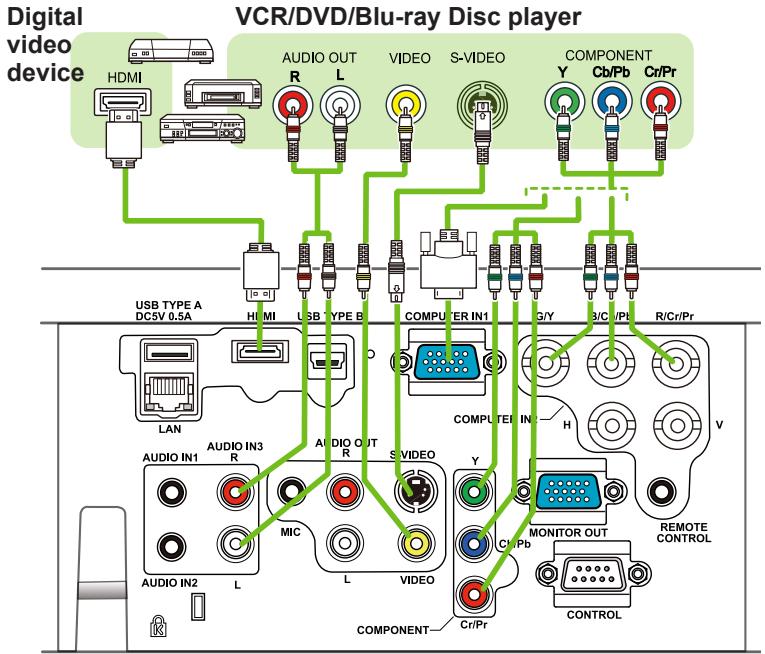
Connecting with your devices (continued)
flowchart
graph TD
    A["Digital video device"] --> B["HDMI"]
    B --> C["USB TYPE A DC5V 0.5A"]
    C --> D["LAN"]
    D --> E["AUDIO IN1"]
    E --> F["VIDEO IN2"]
    F --> G["COMPONENT"]
    G --> H["COMPUTER IN1"]
    H --> I["G/Y"]
    I --> J["3/C/Pt"]
    J --> K["R/Cr/Pr"]
    K --> L["CONTROL"]
    L --> M["REMOTE CONTROL"]
    M --> N["MONITOR OUT"]
    N --> O["COMPONENT"]
    O --> P["Cr/Pr"]
    P --> Q["S VIDEO"]
    Q --> R["VIDEO"]
    R --> S["MIC"]
    S --> T["AUDIO OUT R"]
    T --> U["COMPONENT"]
    U --> V["COMPUTER IN1"]
    V --> W["G/Y"]
    W --> X["3/C/Pt"]
    X --> Y["R/Cr/Pr"]
NOTE • The HDMI port of this model is compatible with HDCP (High-bandwidth Digital Content Protection) and therefore capable of displaying a video signal from HDCP compatible DVD players or the like.
- The HDMI supports the following video signals: 480i@60,480p@60,576i@50,576p@50,720p@50/60,1080i@50/60,1080p@50/60
- This projector can be connected with another equipment that has HDMI ^™ connector, but with some equipment the projector may not work properly, something like no video.
- Be sure to use an HDMI ^TM cable that has the HDMI ^TM logo.
- When the projector is connected with a device having DVI connector, use a DVI to HDMI™ cable to connect with the HDMI input.
(continued on next page)
Connecting with your devices (continued)
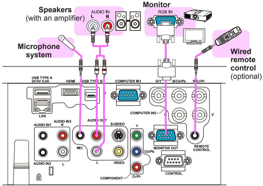
text_image
Speakers (with an amplifier) Audio IN L R Monitor RGB IN Microphone system USB TYPE A DC5V 0.5A HDMI USB TYPE B COMPUTER IN1 G/Y B/Cb/Pb R Cr/Pr Wired remote control (optional) LAN COMPUTER IN2 V AUDIO IN1 AUDIO IN3 R MIC AUDIO OUT S-VIDEO Y Cb/Pb COMPONENT Cr/Pr MONITOR OUT CONTROL REMOTE CONTROLNOTE • If a loud feedback noise is produced from the speaker, move the microphone away from the speaker.
Microphone function
- You can connect a dynamic microphone to the MIC port with a 3.5 mm mini-plug. In that case, the built-in speaker outputs the sound from the microphone, even while the sound from the projector is output. You can input line level signal to the MIC port from equipment such as wireless microphone. Select HIGH in the MIC LEVEL item of the AUDIO menu when you input line level audio signal to the MIC port. In the normal mode, the volume of the microphone can be adjusted separately from the volume of the projector using the menu.
In the standby mode, the volume of the microphone is adjustable with the VOLUME +/- buttons on the remote control, in synchronization with the volume of the projector.
Even when the sound of projector is set to mute mode by the AUDIO SOURCE function, the volume of the microphone is adjustable.
In both modes (standby or normal), the MUTE button on the remote control works on the sounds of the microphone and the projector.
- This projector doesn't support plug-in power for the microphone.
Connecting to a power supply
- Put the connector of the power cord into the AC IN (AC inlet) of the projector.
- Firmly plug the power cord's plug into the outlet. In a couple of seconds after the power supply connection, the POWER indicator will light up in steady orange.
Please remember that when the DIRECT POWER ON function activated, the connection of the power supply make the projector turn on.
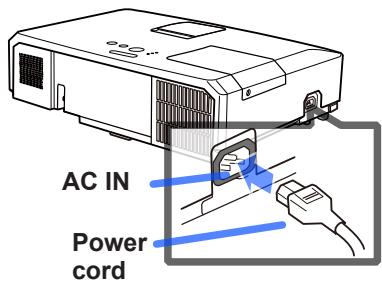
text_image
AC IN Power cord⚠ WARNING ▶ Please use extra caution when connecting the power cord, as incorrect or faulty connections may result in fire and/or electrical shock.
- Only use the power cord that came with the projector. If it is damaged, consult your dealer to get a new one.
- Only plug the power cord into an outlet whose voltage is matched to the power cord. The power outlet should be close to the projector and easily accessible. Remove the power cord for complete separation.
- Never modify the power cord.
Using the security bar and slot
A commercially available anti-theft chain or wire can be attached to the security bar on the projector. Refer to the figure to choose an anti-theft chain or wire.
Also this product has the security slot for the Kensington lock.
For details, see the manual of the security tool.
Anti-theft chain or wire 12mm
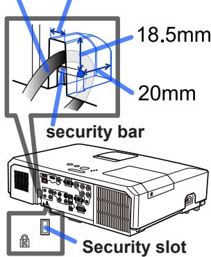
text_image
18.5mm 20mm security bar Security slot⚠ WARNING ▶ Do not use the security bar and slot to prevent the projector from falling down, since it is not designed for it.
⚠ CAUTION ▶ Do not place anti-theft chain or wire near the exhaust vents. It may become too hot.
NOTE • The security bar and slot is not comprehensive theft prevention measures. It is intended to be used as supplemental theft prevention measure.
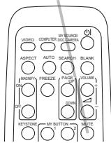
Remote control
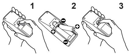
Installing the batteries
Please insert the batteries into the remote control before using it. If the remote control starts to malfunction, try to replace the batteries. If you will not use the remote control for long period, remove the batteries from the remote control and store them in a safe place.
- Holding the hook part of the battery cover, remove it.
- Align and insert the two AA batteries (HITACHI MAXELL, Part No.LR6 or R6P) according to their plus and minus terminals as indicated in the remote control.
- Replace the battery cover in the direction of the arrow and snap it back into place.
text_image
Illustration showing three-step instructions for using a handheld device, labeled 1, 2, and 3.⚠ WARNING ▶ Always handle the batteries with care and use them only as directed. Improper use may result in battery explosion, cracking or leakage, which could result in fire, injury and/or pollution of the surrounding environment.
- Be sure to use only the batteries specified. Do not use batteries of different types at the same time. Do not mix a new battery with used one.
- Make sure the plus and minus terminals are correctly aligned when loading a battery.
- Keep a battery away from children and pets.
- Do not recharge, short circuit, solder or disassemble a battery.
- Do not place a battery in a fire or water. Keep batteries in a dark, cool and dry place.
- If you observe battery leakage, wipe out the leakage and then replace a battery. If the leakage adheres to your body or clothes, rinse well with water immediately.
- Obey the local laws on disposing the battery.
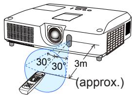
About the remote control signal
The remote control works with the projector's remote sensor. This projector has a remote sensor on the front. The sensor senses the signal within the following range when the sensor is active:
60 degrees (30 degrees to the left and right of the sensor) within 3 meters about.
text_image
30° 30° 3m (approx.)NOTE • The remote control signal reflected in the screen or the like may be available. If it is difficult to send the signal to the sensor directly, attempt to make the signal reflect.
- The remote control uses infrared light to send signals to the projector (Class 1 LED), so be sure to use the remote control in an area free from obstacles that could block the remote control's signal to the projector.
- The remote control may not work correctly if strong light (such as direct sun light) or light from an extremely close range (such as from an inverter fluorescent lamp) shines on the remote sensor of the projector. Adjust the position of projector avoiding those lights.
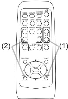
Changing the frequency of remote control signal
The accessory remote control has the two choices on signal frequency Mode 1:NORMAL and Mode 2:HIGH. If the remote control does not function properly, attempt to change the signal frequency. In order to set the Mode, please keep pressing the combination of two buttons listed below simultaneously for about 3 seconds.
(1) Set to Mode 1: NORMAL... VOLUME - and RESET buttons
(2) Set to Mode 2:HIGH... MAGNIFY OFF and ESC buttons
Please remember that the REMOTE FREQ. in the SERVICE item of the OPTION menu of the projector to be controlled should be set to the same mode as the remote control.
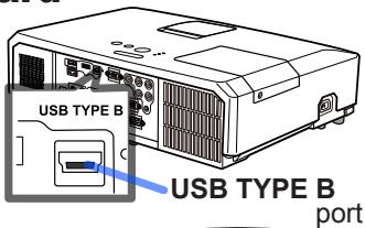
Using as a simple PC mouse & keyboard
The accessory remote control works as a simple mouse and keyboard of the computer, when the projector's USB TYPE B port and the computer's type A USB port are connected and MOUSE is selected for the USB TYPE B item in the OPTION menu.
(1) PAGE UP key: Press PAGE UP button.
(2) PAGE DOWN key: Press PAGE DOWN button.
(3) Mouse left button: Press ENTER button.
(4) Move pointer: Use the cursor buttons ▲, ▼, ◀ and ▶.
(5) ESC key: Press ESC button.
(6) Mouse right button: Press RESET button.
⚠ NOTICE ▶ Improper use of the simple mouse & keyboard function could damage your equipment. While using this function, please connect this product only to a computer. Be sure to check your computer's manuals before connecting this product to the computer.
text_image
USB TYPE B USB TYPE B port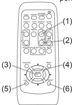
text_image
(1) (2) (3) (4) (5) (6)NOTE When the simple mouse & keyboard function of this product does not work correctly, please check the following.
- When a USB cable connects this projector with a computer having a built-in pointing device (e.g. track ball) like a laptop PC, open BIOS setup menu, then select the external mouse and disable the built-in pointing device, because the built-in pointing device may have priority to this function.
- Windows 95 OSR 2.1 or higher is required for this function. And also this function may not work depending on the computer's configurations and mouse drivers. This function can work with the computer which can operate general USB mouse or keyboard.
- You cannot do things like press two buttons at once (for instance, pressing two buttons at the same time to move the mouse pointer diagonally).
- This function is activated only when the projector is working properly. This function is not available in any of the following cases:
- While the lamp is warming up. (The POWER indicator blinks in green.)
- When either USB TYPE A or USB TYPE B port is selected.
- While displaying BLANK, TEMPLATE or MY IMAGE screen.
- When any menu is displayed on the screen.
- While using the cursor buttons to operate the sound or screen functions such as adjusting the sound volume, correcting the keystone, correcting the picture position and magnifying the screen.
Power on/off
Turning on the power
- Make sure that the power cord is firmly and correctly connected to the projector and the outlet.
- Make sure that the POWER indicator is steady orange. Then remove the lens cover.
- Press STANDBY/ON button on the projector or the remote control.
The projection lamp will light up and POWER indicator will begin blinking in green. When the
power is completely on, the indicator will stop blinking and light in steady green.
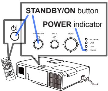
text_image
STANDBY/ON button POWER indicator SINDBY/ON INPUT MENU SECURITY LAMP TEMP POWERTo display the picture, select an input signal according to the section Selecting an input signal.
Turning off the power
- Press the STANDBY/ON button on the projector or the remote control. The message "Power off?" will appear on the screen for about 5 seconds.
- Press the STANDBY/ON button again while the message appears. The projector lamp will go off, and the POWER indicator will begin blinking in orange. Then POWER indicator will stop blinking and light in steady orange when the lamp cooling is complete.
- Attach the lens cover, after the POWER indicator turns in steady orange.
Do not turn the projector on for about 10 minutes or more after turning it off. Also, do not turn the projector off shortly after turning it on. Such operations might cause the lamp to malfunction or shorten the lifetime of some parts including the lamp.
WARNING
▶ A strong light is emitted when the projector's power is on.
Do not look into the lens of the projector or look inside of the projector through any of the projector's openings.
▶ Do not touch around the lamp cover and the exhaust vents during use or just after use, since it is too hot.
NOTE • Turn the power on/off in right order. Please power on the projector prior to the connected devices.
- This projector has the function that can make the projector automatically turn on/off. Please refer to the DIRECT POWER ON and AUTO POWER OFF items of the OPTION menu.
- Use the shutdown switch only when the projector is not turned off by normal procedure.
Operating
VOLUME +/- button
Adjusting the volume
1 Use the VOLUME +/VOLUME - buttons to adjust the volume.
- A dialog will appear on the screen to aid you in adjusting the volume. If you do not do anything, the dialog will automatically disappear after a few seconds.
- When ✗ is selected for current picture input port, the volume adjustment is disabled. Please see AUDIO SOURCE item of AUDIO menu.
- Even if the projector is in the standby mode, the volume is adjustable when both of the following conditions are true:
- An option other than ✗ is selected for STANDBY in the AUDIO SOURCE item of the AUDIO menu.
- NORMAL is selected in the STANDBY MODE item of the SETUP menu.
- In the standby mode, the volume of the microphone is adjustable with the VOLUME +/- buttons on the remote control, in synchronization with the volume of the projector.
Temporarily muting the sound
1 Press MUTE button on the remote control.
A dialog will appear on the screen indicating that you have muted the sound.
To restore the sound, press the MUTE, VOLUME + or VOLUME - button. Even if you do not do anything, the dialog will automatically disappear after a few seconds.
MUTE button
text_image
VIDEO COMPUTER MY SOURCE ASPECT AUTO SEARCH BLANK MOUNT FREEZE PAGE VOLUME ON UP ON DOWN KEystone MY BUTTON MUTE- When ✗ is selected for current picture input port, the sound is always muted. Please see AUDIO SOURCE item of AUDIO menu.
- C.C. (Closed Caption) is automatically activated when sound is muted and an input signal containing C.C. is received. This function is available only when the signal is NTSC for VIDEO or S-VIDEO, or 480i@60 for COMPONENT, COMPUTER IN1 or COMPUTER IN2, and when AUTO is selected for DISPLAY in the C.C. menu under the SCREEN menu.
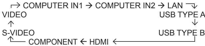
Selecting an input signal
1 Press INPUT button on the projector.
- Each time you press the button, the projector switches its input port from the current port as below.
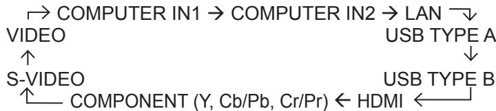
flowchart
graph TD
    A["→ COMPUTER IN1 → COMPUTER IN2 → LAN"] --> B["VIDEO"]
    B --> C["S-VIDEO"]
    C --> D["COMPONENT (Y, Cb/Pb, Cr/Pr) ← HDMI ←"]
    B --> E["USB TYPE A ↓"]
    C --> F["USB TYPE B"]
text_image
INPUT button STATION OUTPUT MDAU- While ON is selected for AUTO SEARCH item in OPTION menu, the projector will keep checking the ports in above order repeatedly till an input signal is detected.
- It may take several seconds to project the images from the USB TYPE B port.
Selecting an input signal (continued)
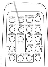
1 Press COMPUTER button on the remote control.
Each time you press the button, the projector switches its input port from the current port as below.

flowchart
graph TD
    A["→ COMPUTER IN1 → COMPUTER IN2 → LAN"] --> B["USB TYPE B ← USB TYPE A ←"]
- While ON is selected for AUTO SEARCH item in OPTION menu, the projector will keep checking every port sequentially till an input signal is detected. If COMPUTER button is pressed when VIDEO, S-VIDEO, COMPONENT or HDMI port is selected, the projector will check COMPUTER IN1 port first.
- It may take several seconds to project the images from the USB TYPE B port.
COMPUTER button
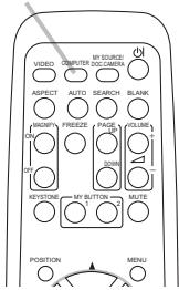
text_image
VIDEO COMPUTER SOCCAMBI ASPECT AUTO SEARCH BLANK MAGIFY FREEZE PAGE LINE ON GOBI KEYSTONE MY BUTTON MUTE 1 2 3 4 5 6 7 8 9 10 11 12 13 14 15 16 17 18 19 20 21 22 23 24 25 26 27 28 29 30 31 32 33 34 35 36 37 38 39 40 41 42 43 44 45 46 47 48 49 50 51 52 53 54 55 56 57 58 59 60 61 62 63 64 65 66 67 68 69 70 71 72 73 74 75 76 77 78 79 80 81 82 83 84 85 86 87 88 89 90 91 92 93 94 95 96 97 98 99 1001 Press VIDEO button on the remote control.
- Each time you press the button, the projector switches its input port from the current port as below.

flowchart
graph LR
    A["→ HDMI → COMPONENT → S-VIDEO → VIDEO"] --> B["—"]
- While ON is selected for AUTO SEARCH item in OPTION menu, the projector will keep checking every port sequentially till an input signal is detected. If VIDEO button is pressed when COMPUTER IN1, COMPUTER IN2, LAN, USB TYPE A or USB TYPE B port is selected, the projector will check HDMI port first.
VIDEO button
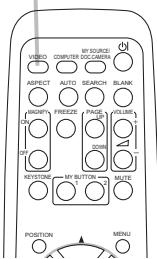
text_image
VIDEO ASPECT MAGNIFY ON BEYSTONE MY SOURCE COMPUTER COCAMERA AUTO SEARCH SLANK PAGE DOWN FUSE HOLE MOZZARES MOZZARES MOZZARES MOZZARES MOZZARES MOZZARES MOZZARES MOZZARES MOZZARES MOZZARES MOZZARES MOZZARES MOZZARES MOZZARES MOZZARES MOZZARES MOZZARES MOZZARES MOZZARES MOZZARES MOZZARE MOZZARES MOZZARES MOZZARES MOZZARES MOZZARES MOZZARES MOZZARES MOZZARES MOZZARES MOZZARES MOZZARES MOZZARES MOZZARES MOZZARES MOZZARES MOZZARES MOZZARES MOZZARES MOZZARES MOZZAREs MOZZAREs MOZZAREs MOZZAREs MOZZAREs MOZZAREs MOZZAREs MOZZAREs MOZZAREs MOZZAREs MOZZAREs MOZZAREs MOZZAREs MOZZAREs MOZZAREs MOZZAREs MOZZAREs MOZZAREs MOZZAREs MOZZAREs MOZZAREe MOZZAREe MOZZAREe MOZZAREe MOZZAREe MOZZAREe MOZZAREe MOZZAREe MOZZAREe MOZZAREe MOZZAREe MOZZAREe MOZZAREe MOZZAREe MOZZAREe MOZZAREe MOZZAREe MOZZAREe1. Press the MY SOURCE / DOC. CAMERA button on the remote control. The input signal will be changed into the signal you set as MY SOURCE.
- This function also can use for document camera. Select the input port that connected the document camera.
MY SOURCE / DOC. CAMERA button
text_image
VIDEO COMPUTER SOURCE ASPECT AUTO SEARCH BLANK MKNIFY FREEZE PAGE CLOSE OK D BESTONE MY BUTTON MUTE POSITION MENUSearching an input signal
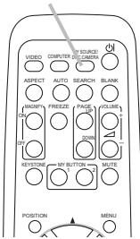
1 Press SEARCH button on the remote control.
- The projector will start to check its input ports as below in order to find any input signals.
When an input is found, the projector will stop searching and display the image. If no signal is found, the projector will return to the state selected before the operation.
flowchart
graph TD
    A["→ COMPUTER IN1 → COMPUTER IN2 → LAN"] --> B["VIDEO"]
    B --> C["S-VIDEO"]
    C --> D["COMPONENT ← HDMI ←"]
    D --> E["USB TYPE A"]
    E --> F["↓"]
    F --> G["USB TYPE B"]
SEARCH button
text_image
VIDEO MY SOURCE COMPUTER BEIJING ASPECT AUTO SEARCH BLANK MOUNT FREEZE PAGE VOLUME 01 02 03 04 05 06 07 08 09 10 11 12 13 14 15 16 17 18 19 20 21 22 23 24 25 26 27 28 29 30 31 32 33 34 35 36 37 38 39 40 41 42 43 44 45 46 47 48 49 50 51 52 53 54 55 56 57 58 59 60 61 62 63 64 65 66 67 68 69 70 KEYSTONE MY BUTTON MUTE 01 02 03 04 05 06 07 08 09 10 11 12 13 14 15 16 17 18 19 20 POSITION MENU- While ON is selected for AUTO SEARCH item in OPTION menu, the projector will keep checking the ports in above order repeatedly till an input signal is detected.
- It may take several seconds to project the images from the USB TYPE B port.
Selecting an aspect ratio
1 Press ASPECT button on the remote control.
Each time you press the button, the projector switches the mode for aspect ratio in turn.
○ For a computer signal
NORMAL ⇔ 4:3 ⇔ 16:9 ⇔ 16:10

○ For an HDMI™ signal
NORMAL ⇔ 4:3 ⇔ 16:9 ⇔ 16:10 ⇔ 14:9

ASPECT button

text_image
VIDEO ASPECT MACIFY ON/OFF BEET/STOCK MY SOURCE COMPUTER COCUMBERA AUTO SEARCH PAGE 1 PAGE 2 PAGE 3 PAGE 4 PAGE 5 PAGE 6 PAGE 7 PAGE 8 PAGE 9 PAGE 10 PAGE 11 PAGE 12 PAGE 13 PAGE 14 PAGE 15 PAGE 16 PAGE 17 PAGE 18 PAGE 19 PAGE 20 PAGE 21 PAGE 22 PAGE 23 PAGE 24 PAGE 25 PAGE 26 PAGE 27 PAGE 28 PAGE 29 PAGE 30 PAGE 31 PAGE 32 PAGE 33 PAGE 34 PAGE 35 PAGE 36 PAGE 37 PAGE 38 PAGE 39 PAGE 40 PAGE 41 PAGE 42 PAGE 43 PAGE 44 PAGE 45 PAGE 46 PAGE 47 PAGE 48 PAGE 49 PAGE 50 PAGE 51 PAGE 52 PAGE 53 PAGE 54 PAGE 55 PAGE 56 PAGE 57 PAGE 58 PAGE 59 PAGE 60 PAGE 61 PAGE 62 PAGE 63 PAGE 64 PAGE 65 PAGE 66 PAGE 67 PAGE 68 PAGE 69 PAGE 70 PAGE 71 PAGE 72 PAGE 73 PAGE 74 PAGE 75 PAGE 76 PAGE 77 PAGE 78 PAGE 79 PAGE 80 PAGE 81 PAGE 82 PAGE 83 PAGE 84 PAGE 85 PAGE 86 PAGE 87 PAGE 88 PAGE 89 PAGE 90 PAGE 91 PAGE 92 PAGE 93 PAGE 94 PAGE 95 PAGE 96 PAGE 97 PAGE 98 PAGE 99 PAGE 100○ For a video signal, s-video signal or component video signal
4:3 16:9 14:9

☐ For an input signal from the LAN, USB TYPE A or USB TYPE B port, or if there is no signal
- ASPECT button does not work when no proper signal is inputted.
- NORMAL mode keeps the original aspect ratio setting.
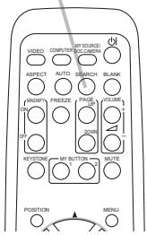
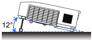
Adjusting the projector's elevator
When the place to put the projector is slightly uneven to the left or right, use the elevator feet to place the projector horizontally.
Using the feet can also tilt the projector in order to project at a suitable angle to the screen, elevating the front side of the projector within 12 degrees.
This projector has 2 elevator feet and 2 elevator buttons. An elevator foot is adjustable while pushing the elevator button on the same side as it.
- Holding the projector, push the elevator buttons to loose the elevator feet.
- Position the front side of the projector to the desired height.
- Release the elevator buttons in order to lock the elevator feet.
- After making sure that the elevator feet are locked, put the projector down gently.
- If necessary, the elevator feet can be manually twisted to make more precise adjustments. Hold the projector when twisting the feet.
text_image
12°
text_image
To loose an elevator foot, push the elevator button on the same side as it.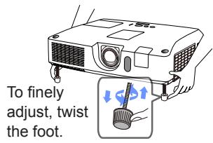
text_image
To finely adjust, twist the foot.⚠ CAUTION ▶ Do not handle the elevator buttons without holding the projector, since the projector may drop down.
▶ Do not tilt the projector other than elevating its front within 12 degrees using the adjuster feet. A tilt of the projector exceeding the restriction could cause malfunction or shortening the lifetime of consumables, or the projector itself.
Adjusting the lens
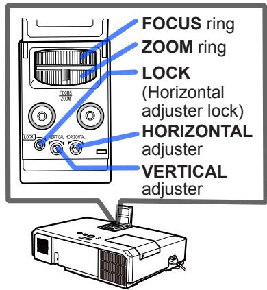
- Use the ZOOM ring to adjust the screen size.
- Use the FOCUS ring to focus the picture.
- Turn the VERTICAL adjuster fully counter clockwise. Then turn it clockwise and adjust the vertical lens position upward.
- Turn the LOCK counter clockwise to loosen the lock of the HORIZONTAL adjuster.
- Turn the HORIZONTAL adjuster clockwise or counter clockwise to adjust the horizontal lens position.
-
Use the FOCUS ring to focus the picture.
-
Turn the LOCK fully clockwise to tighten it and lock the horizontal lens position.
text_image
FOCUS ring ZOOM ring LOCK (Horizontal adjuster lock) HORIZONTAL adjuster VERTICAL adjuster⚠️ CAUTION ▶ Operate the lens adjusters gently as the lens may malfunction when subjected to shocks. It may need more strength to turn the adjusters near the adjustment limits. Be careful not to apply too much strength.
NOTE • Use a hexagon wrench to turn the VERTICAL, HORIZONTAL adjusters and LOCK. If you do not have a hexagon wrench, you can use a flathead screwdriver with more careful handling.
- Use the LOCK so that the lens does not shift from the adjusted horizontal lens position. Adjusting the vertical lens position may shift the horizontal lens position. This projector is not equipped with a lock for vertical lens position.
Using the automatic adjustment feature
- Press AUTO button on the remote control. Pressing this button performs the following
○ For a computer signal
The vertical position, the horizontal position and the horizontal phase will be automatically adjusted.
Make sure that the application window is set to its maximum size prior to attempting to use this feature. A dark picture may still be incorrectly adjusted. Use a bright picture when adjusting.
AUTO button
text_image
VIDEO COMPUTER C/CAMBR BY SOURCE ASPECT AUTO SEARCH BLANK INRIP FRIEZE PAGE VOLUME ON ON KEYSTONE MY BUTTON MUTE○ For a video signal and s-video signal
The video format best suited for the respective input signal will be selected automatically. This function is available only when the AUTO is selected for the VIDEO FORMAT item in the INPUT menu. The vertical position and horizontal position will be automatically set to the default.
○ For a component video signal
The vertical position and horizontal position will be automatically set to the default. The horizontal phase will be automatically adjusted.
- The automatic adjustment operation requires approx. 10 seconds. Also please note that it may not function correctly with some input.
- When this function is performed for a video signal, a certain extra such as a line may appear outside a picture.
- When this function is performed for a computer signal, a black frame may be displayed on the edge of the screen, depending on the PC model.
- The items adjusted by this function may vary when the FINE or DISABLE is selected for the AUTO ADJUST item of the SERVICE item in the OPTION menu.
Adjusting the position
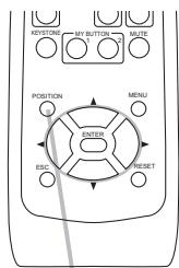
- Press POSITION button on the remote control when no menu is indicated.
The “POSITION” indication will appear on the screen.
2 Use the ▲/▼/◄/► cursor buttons to adjust the picture position.
- When you want to reset the operation, press RESET button on the remote control during the operation.
To complete this operation, press POSITION button again. Even if you do not do anything, the dialog will automatically disappear after a few seconds.
text_image
KEYSTONE MY BUTTON MUTE POSITION MENU ENTER ESC SHIFTPOSITION button
- When this function is performed on a video signal or an s-video signal, some image such as an extra-line may appear at outside of the picture.
- When this function is performed on a video signal or s-video signal, the range of this adjustment depends on OVER SCAN in IMAGE menu setting. It is not possible to adjust when OVER SCAN is set to 10.
- If POSITION button is pressed when a menu is indicated on screen, the displayed picture does not move its position but the menu does.
- This function is unavailable for a signal from the LAN, USB TYPE A, USB TYPE B or HDMI port.
Correcting the distortion
To correct the distortion of projected screen, you can select one of three options, AUTO, MANUAL and PERFECT FIT.
AUTO: performs the automatic vertical keystone correction.
MANUAL: allows you to adjust the vertical and horizontal keystone.
PERFECT FIT: allows you to adjust each of the screen corners and sides to correct the distortion.
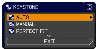
text_image
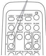
KEYSTONE AUTO MANUAL PERFECT FIT EXIT- First press the KEYSTONE button to display the KEYSTONE menu, and point at one of items with the ▲/▼ buttons. Then follow the procedure shown below for the item you selected.
NOTE • The menu or dialog will automatically disappear after several seconds of inactivity. Pressing the KEYSTONE button again finishes the operation and closes the menu or dialog.
- When the screen is adjusted by PERFECT FIT, neither AUTO nor MANUAL is selectable. If you wish to use these functions, refer to step 3 in the PERFECT FIT item to initialize the adjustment of PERFECT FIT.
- When TRANSITION DETECTOR is ON, these functions are not available.
AUTO
- When AUTO is pointed at, pressing the ▶ or ENTER button performs automatic vertical keystone correction. To close the operation, press the KEYSTONE button, or pointed at the EXIT in the dialog with ▲/▼ buttons and press the ▶ or ENTER button.
MANUAL
- When MANUAL is pointed at, pressing the ▶ or ENTER button displays the KEYSTONE_MANUAL dialog.
- Select the vertical or horizontal keystone (A / E) with the ▲/▼ buttons.
- Use the ◀/▶ buttons to adjust the keystone distortion.
- To close the operation, press the KEYSTONE button, or pointed at the EXIT in the dialog with ▲/▼ buttons and press the ▶ or ENTER button. Alternatively, point at RETURN in the dialog with the ▲/▼ buttons and press the ◀ or ENTER button to return to the menu in step 1.
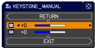
text_image
& KEYSTONE_MANUAL RETURN +0 +0 EXITPERFECT FIT
- When PERFECT FIT is pointed at, pressing the ▶ or ENTER button displays the KEYSTONE_PERFECT FIT dialog.
- If it is necessary to initialize the current adjustment, point at RESET in the dialog with the RESET button, and press the ENTER or INPUT button.
-
Select one of the corners or sides to be adjusted with the ▲/▼/◄/► buttons and press the ENTER or INPUT button.
-
Adjust the selected part as below.
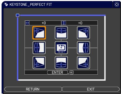
text_image
KEYSTONE_PERFECT FIT +0 +0 (↓) RESET ENTER RETURN EXIT- For adjusting a corner, use the ▲/▼/◄/► buttons to adjust the position of the corner.
- For adjusting the upper or lower side, use the ◀/▶ buttons to select any one point on the side, and use the ▲/▼ buttons to adjust the distortion of the side.
- For adjusting the left or right side, use the ▲/▼ buttons to select any one point on the side, and use the ◀/▶ buttons to adjust the distortion of the side.
- To adjust another corner or side press the ENTER or INPUT button and follow the procedure from step 4.
NOTE • Each corner and side can be adjusted individually but in some cases it may be adjusted in conjunction with another corner or side. This is due to control restrictions and not a malfunction.
- To close the operation, press the KEYSTONE button, or point at EXIT in the dialog with ▲/▼ buttons and press the ▶ or ENTER button. Alternatively, point at RETURN in the dialog with the ▲/▼ buttons and press the ◀ or ENTER button to return to the menu in step 1.
Using the magnify feature
- Press the MAGNIFY ON button on the remote control. The picture will be magnified, and the MAGNIFY dialog will appear on the screen. When the MAGNIFY ON button is pressed for the first time after the projector is turned on, the picture will be zoomed by 1.5 times. On the dialog, triangle marks to show each direction will be displayed.
- While the triangles are displayed on the dialog, use the ▲/▼/◄/► cursor buttons to shift the magnifying area.
- A magnifying glass icon will be displayed on the dialog when the MAGNIFY ON button is pressed while the dialog with the triangles is displayed.
- While the magnifying glass icon is displayed on the dialog, use the ▲/▼ cursor buttons to adjust the magnification ratio. The magnification ratio will be adjusted with fine steps. And changes in the ratio in single steps are subtle so they may be hard to recognize.
-
Press the MAGNIFY OFF button on the remote control to exit magnification.
-
The MAGNIFY dialog will automatically disappear in several seconds with no operation. The dialog will appear again if the MAGNIFY ON button is pressed when the dialog has automatically disappeared.
- While the MAGNIFY dialog is displayed, press the MAGNIFY ON button to switch the dialog between magnifying area shifting (with the triangles) and magnification ratio adjustment (with the magnifying glass icon).
- The magnification is automatically disabled when the displaying signal or its display condition is changed.
- While the magnification is active, the keystone distortion condition may vary. It will be restored when the magnification is disabled.
- Some horizontal stripes might be visible on the image while magnification is active.
-
This function is not available in the following cases:
-
The USB TYPE A port is selected as the input source.
- A sync signal in the range not supported is input.
- There is no input signal.
MAGNIFY
ON/OFF button
text_image
VIDEO COMPUTER MY SOURCE DC-COMBER ASPECT AUTO SEARCH BLANK AGNETT FREEZE PAGE ON VOLUME ON DOWN VEGETABLES KEystone MY BUTTON MUTETemporarily freezing the screen
FREEZE button
1 Press the FREEZE button on the remote control.
- The “FREEZE” indication will appear on the screen (however, the indication will not appear when the OFF is selected for the MESSAGE item in the SCREEN menu), and the projector will go into the FREEZE mode, which the picture is frozen. To exit the FREEZE mode and restore the screen to normal, press the FREEZE button again.
text_image
VIDEO COMPUTER COMPARA MY SOURCE DCC CHINA ASPECT AUTO SEARCH BLANK MAGIFY FREEZE PAGE USS VOLUME ON DOWN TOWN KEYSTONE MY BUTTON MUTE- The projector automatically exits from the FREEZE mode when some control buttons are pressed.
- If the projector continues projecting a still image for a long time, the LCD panel might possibly be burned in. Do not leave the projector in the FREEZE mode for too long.
- Images might appear degraded when this function is operated, but it is not a malfunction.
Temporarily blanking the screen
1 Press BLANK button on the remote control.
- The BLANK screen will be displayed instead of the screen of input signal. Please refer to BLANK item in SCREEN menu. To exit from the BLANK screen and return to the input signal screen, press BLANK button again.
- The projector automatically exits from the BLANK mode when some control buttons are pressed.
BLANK button
text_image
VIDEO COMPUTER OFFCHARGE ASPECT AUTO SEARCH BLANK IMONYL FREEZE PAGE FIGURE OK ON OK ON KEYSTONE MY BUTTON MUTE⚠️CAUTION ▶ If you wish to have a blank screen while the projector's lamp is on, use the BLANK function above.
Taking any other action may cause the damage on the projector.
NOTE • The sound is not connected with the BLANK screen function. If necessary, set the volume or mute first. To display the BLANK screen and mute the sound at one time, use AV MUTE function.
Using the menu function
This projector has the following menus:
PICTURE, IMAGE, INPUT, SETUP, AUDIO, SCREEN, OPTION, NETWORK, SECURITY and EASY MENU.
EASY MENU consists of functions often used, and the other menus are classified into each purpose and brought together as the ADVANCED MENU.
Each of these menus is operated using the same methods. While the projector is displaying any menu, the MENU button on the projector works as the cursor buttons. The basic operations of these menus are as follows.
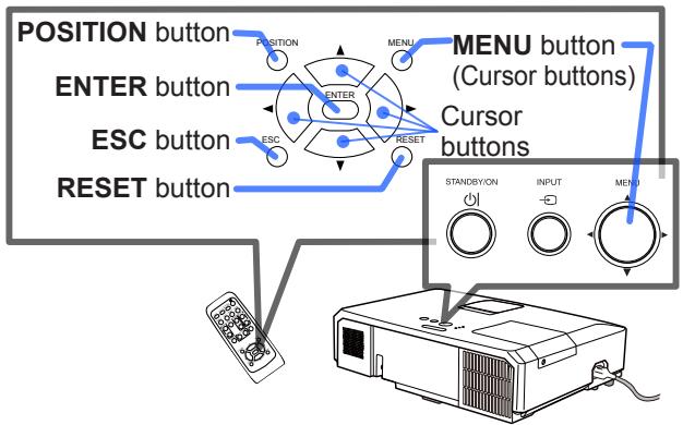
flowchart
graph TD
    A["Position button"] --> B["ENTER button"]
    B --> C["ESC button"]
    C --> D["RESET button"]
    E["MENU button (Cursor buttons)"] --> F["Cursor buttons"]
    G["STANDBYON"] --> H["INPUT"]
    I["MENU"] --> J["OUTPUT"]
-
To start the MENU, press the MENU button. The MENU you last used (EASY or ADVANCED) will appear. EASY MENU has priority to appear just after powered on.
-
In the EASY MENU
(1) Use the ▲/▼ cursor buttons to select an item to operate. If you want to change it to the ADVANCED MENU, select the ADVANCED MENU.
(2) Use the ◀/▶ cursor buttons to operate the item.
In the ADVANCED MENU
(1) Use the ▲/▼ cursor buttons to select a menu. If you want to change it to the EASY MENU, select the EASY MENU.
The items in the menu appear on the right side.
(2) Press the ▶ cursor button or ENTER button to move the cursor to the right side. Then use the
▲/▼ cursor buttons to select an item to operate and press the ▶ cursor button or ENTER button to progress. The operation menu or dialog of the selected item will appear.
(3) Use the buttons as instructed in the OSD to operate the item.
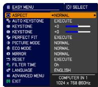
text_image
EASY MENU ASPECT AUTO KEYSTONE KEYSTONE PERFECT FIT PICTURE MODE ECO MODE MIRROR RESET FILTER TIME LANGUAGE ADVANCED MENU EXIT NORMAL EXECUTE +0 +0 EXECUTE NORMAL NORMAL EXECUTE Oh ENGLISH COMPUTER IN 1 1024 x 768 @0Hz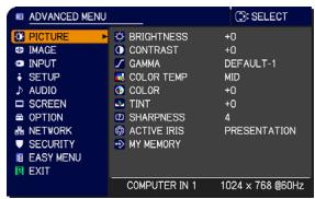
text_image
ADANCED MENU PICTURE BRIGHTNESS +0 IMAGE CONTRAST +0 INPUT PARAMETER DEFAULT-1 SETUP COLOR TEMP MID AUDIO COLOR +0 SCREEN TINT +0 OPTION SHARPNESS 4 NETWORK ACTIVE IRIS PRESENTATION SECURITY MY MEMORY EASY MENU EXIT COMPUTER IN 1 1024 x 768 @60Hz(continued on next page)
Using the menu function (continued)
-
To close the MENU, press the MENU button again or select EXIT and press the ◀ cursor button or ENTER button. Even if you do not do anything, the dialog will automatically disappear after about 30 seconds.
-
If you want to move the menu position, use the cursor buttons after pressing the POSITION button.
- Some functions cannot be performed when a certain input port is selected, or when a certain input signal is displayed.
- When you want to reset the operation, press RESET button on the remote control during the operation. Note that some items (ex. LANGUAGE, VOLUME) cannot be reset.
- In the ADVANCED MENU, when you want to return to the previous display, press the ◀ cursor button or ESC button on the remote control.
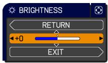
Indication in OSD (On Screen Display)
text_image
BRIGHTNESS RETURN +0 EXIT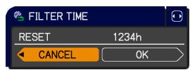
text_image
FILTER TIME RESET 1234h CANCEL OK
text_image
4 MY MEMORY_LOAD-4 TEMPORARY CONDITION ARE YOU SURE YOU WISH TO LOAD? NO YESThe meanings of the general words on the OSD are as follows.
| Indication | Meaning |
| EXIT | Selecting this word finishes the OSD menu. It's the same as pressing the MENU button. |
| RETURN | Selecting this word returns the menu to the previous menu. |
| CANCEL or NO | Selecting this word cancels the operation in the present menu and returns to the previous menu. |
| OK or YES | Selecting this word executes the prepared function or shifts the menu to the next menu. |
EASY MENU
From the EASY MENU, items shown in the table below can be performed.
Select an item using the ▲/▼ cursor buttons. Then perform it according to the following table.
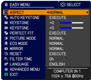
text_image
EASY MENU ASPECT AUTO KEYSTONE KEYSTONE PERFECT FIT PICTURE MODE ECO MODE MIRROR RESET FILTER TIME LANGUAGE ADVANCED MENU EXIT NORMAL EXECUTE +0 +0 EXECUTE NORMAL NORMAL NORMAL EXECUTE Oh ENGLISH COMPUTER IN 1 1024 x 768 @60Hz| Item | Description | ||
| ASPECT | Using the ◀/► buttons switches the mode for aspect ratio.See the ASPECT item in IMAGE menu. | ||
| AUTO KEYSTONE | Using the ► button executes the auto keystone function.See the AUTO KEYSTONE item in SETUP menu. | ||
| KEYSTONE | Using the ◀/► buttons corrects the vertical keystone distortion.See the KEYSTONE item in SETUP menu. | ||
| KEYSTONE | Using the ◀/► buttons corrects the horizontal keystone distortion.See the KEYSTONE in SETUP menu. | ||
| PERFECT FIT | Pressing the ► button displays the KEYSTONE_PERFECT FIT dialog. See the PERFECT FIT item in SETUP menu. | ||
| PICTURE MODE | Using the ◀/► buttons switches the picture mode.The picture modes are combinations of GAMMA and COLOR TEMP settings. Choose a suitable mode according to the projected source.NORMAL ⇔ CINEMA ⇔ DYNAMIC ⇔ BOARD(BLACK)DAYLIGHT ⇔ WHITEBOARD ⇔ BOARD(GREEN) | ||
| GAMMA | COLOR TEMP | ||
| NORMAL | 1 DEFAULT | 2 MID | |
| CINEMA | 2 DEFAULT | 3 LOW | |
| DYNAMIC | 3 DEFAULT | 1 HIGH | |
| BOARD(BLACK) | 4 DEFAULT | 4 Hi-BRIGHT-1 | |
| BOARD(GREEN) | 4 DEFAULT | 5 Hi-BRIGHT-2 | |
| WHITEBOARD | 5 DEFAULT | 2 MID | |
| Daylight Mode | 6 DEFAULT | 6 Hi-BRIGHT-3 | |
| When the combination of GAMMA and COLOR TEMP differs from pre-assigned modes above, the display on the menu for the PICTURE MODE is “CUSTOM”. Please refer to the GAMMA and COLOR TEMP items in PICTURE menu.Lines or other noise might appear on the screen when this function is operated, but it is not a malfunction. | |||
| Item | Description | ||
| ECO MODE | Using the ◀/► buttons turns off/on the Eco mode.See the ECO MODE item in SETUP menu. | ||
| MIRROR | Using the ◀/► buttons switches the mode for mirror status.See the MIRROR item in SETUP menu. | ||
| RESET | Performing this item resets all of the EASY MENU items except the FILTER TIME and LANGUAGE.A dialog is displayed for confirmation. Selecting the OK using the ► button performs resetting. | ||
| FILTER TIME | The usage time of the air filter is shown in the menu.Performing this item resets the filter time which counts usage time of the air filter.A dialog is displayed for confirmation. Selecting the OK using the ► button performs resetting.See the FILTER TIME item in OPTION menu. | ||
| LANGUAGE | Using the ◀/► buttons changes the display language.See the LANGUAGE item in SCREEN menu. | ||
| ADVANCED MENU | Press the ► or ENTER button to use the menu of PICTURE, IMAGE, INPUT, SETUP, AUDIO, SCREEN, OPTION, NETWORK or SECURITY. | ||
| EXIT | Press the ◀ or ENTER button to finish the OSD menu. | ||
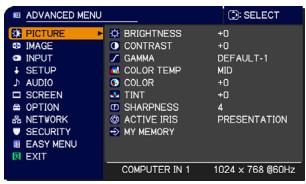
PICTURE menu
From the PICTURE menu, items shown in the table below can be performed.
Select an item using the ▲/▼ cursor buttons, and press the ▶ cursor button or ENTER button to execute the item. Then perform it according to the following table.
text_image
ADANCED MENU TITLE IMAGE INPUT SETUP AUDIO SCREEN OPTION NETWORK SECURITY EASY MENU EXIT BRIGHTNESS CONTRAST GAMMA COLOR TEMP TINY SHARNESS ACTIVE IRIS MY MEMORY +0 +0 DEFAULT-1 MID +0 +0 4. PRESENTATION COMPUTER IN 1 1024 x 768 @60Hz| Item | Description |
| BRIGHTNESS | Using the ◀/► buttons adjusts the brightness.Dark ⇔ Light |
| CONTRAST | Using the ◀/► buttons adjusts the contrast.Weak ⇔ Strong |
| GAMMA | Using the ▲/▼ buttons switches the gamma mode.1 DEFAULT ⇔ 1 CUSTOM ⇔ 2 DEFAULT ⇔ 2 CUSTOM ⇔ 3 DEFAULT6 CUSTOM 3 CUSTOM6 DEFAULT ⇔ 5 CUSTOM ⇔ 5 DEFAULT ⇔ 4 CUSTOM ⇔ 4 DEFAULTTo adjust CUSTOMSelecting a mode whose name includes CUSTOM and then pressing the ► button or the ENTER button displays a dialog to aid you in adjusting the mode.This function is useful when you want to change the brightness of particular tones. 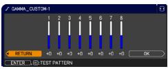 Choose an item using the ◀/► buttons, and adjust the level using the ▲/▼ buttons.You can display a test pattern for checking the effect of your adjustment by pressing the ENTER button.Each time you press the ENTER button, the pattern changes as below.No pattern ⇒ Gray scale of 9 steps Choose an item using the ◀/► buttons, and adjust the level using the ▲/▼ buttons.You can display a test pattern for checking the effect of your adjustment by pressing the ENTER button.Each time you press the ENTER button, the pattern changes as below.No pattern ⇒ Gray scale of 9 steps 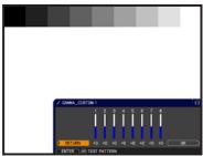 Ramp ⇔ Gray scale of 15 stepsThe eight equalizing bars correspond to eight tone levels of the test pattern (Gray scale of 9 steps) except the darkest in the left end. If you want to adjust the 2nd tone from left end on the test pattern, use the equalizing adjustment bar “1”. The darkest tone at the left end of the test pattern cannot be controlled with any of equalizing adjustment bar.• Lines or other noise might appear on the screen when this function is operated, but it is not a malfunction. Ramp ⇔ Gray scale of 15 stepsThe eight equalizing bars correspond to eight tone levels of the test pattern (Gray scale of 9 steps) except the darkest in the left end. If you want to adjust the 2nd tone from left end on the test pattern, use the equalizing adjustment bar “1”. The darkest tone at the left end of the test pattern cannot be controlled with any of equalizing adjustment bar.• Lines or other noise might appear on the screen when this function is operated, but it is not a malfunction. 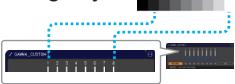 |
(continued on next page)
| Item | Description |
| COLOR TEMP | Using the ▲/▼ buttons switches the color temperature mode.1 HIGH ⇔ 1 CUSTOM ⇔ 2 MID ⇔ 2 CUSTOM6 CUSTOM 3 LOW6 Hi-BRIGHT-3 3 CUSTOM5 CUSTOM ⇔ 5 Hi-BRIGHT-2 ⇔ 4 CUSTOM ⇔ 4 Hi-BRIGHT-1To adjust CUSTOMSelecting a mode whose name includes CUSTOM and then pressing the ▶ buttonor the ENTER button displays a dialog to aid you in adjusting the OFFSET and GAIN of the selected mode.OFFSET adjustments change the color intensity on the whole tones of the test pattern.GAIN adjustments mainly affect color intensity on the brighter tones of the test pattern.Choose an item using the ◀/▶ buttons, and adjust the level using the ▲/▼ buttons.You can display a test pattern for checking the effect of your adjustment by pressing the ENTER button.Each time you press the ENTER button, the pattern changes as below.No pattern ⇒ Gray scale of 9 steps [IMAGE]Ramp ⇔ Gray scale of 15 steps• Lines or other noise might appear on the screen 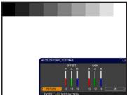 when this function is operated, but it is not a malfunction. when this function is operated, but it is not a malfunction. |
| COLOR | Using the ◀/▶ buttons adjusts the strength of whole color.Weak ⇔ Strong• This item can be selected only for a video, s-video and component video signal.• For an HDMITM signal, this item can also be selected if either (1) or (2) applies.(1) HDMI FORMAT item in the INPUT menu is set to VIDEO.(2) HDMI FORMAT item in the INPUT menu is set to AUTO, and the projector recognizes that it receives video signals. |
| TINT | Using the ◀/▶ buttons adjusts the tint.Reddish ⇔ Greenish• This item can be selected only for a video, s-video and component video signal.• For an HDMITM signal, this item can also be selected if either (1) or (2) applies.(1) HDMI FORMAT item in the INPUT menu is set to VIDEO.(2) HDMI FORMAT item in the INPUT menu is set to AUTO, and the projector recognizes that it receives video signals. |
(continued on next page)
| Item | Description |
| SHARPNESS | Using the ◀/► buttons adjusts the sharpness.Weak ⇔ StrongThere may be some noise and/or the screen may flicker for a moment when an adjustment is made. This is not a malfunction. |
| ACTIVE IRIS | Using the ▲/▼ cursor buttons changes the active iris control mode.PRESENTATION ⇔ THEATER ⇔ OFF PRESENTATION: The active iris displays the best presentation image for both bright and dark scenes.THEATER: The active iris displays the best theater image for both bright and dark scenes.OFF: The active iris is always open.The screen may flicker when the PRESENTATION or THEATER modes are selected. If this occurs select OFF. PRESENTATION: The active iris displays the best presentation image for both bright and dark scenes.THEATER: The active iris displays the best theater image for both bright and dark scenes.OFF: The active iris is always open.The screen may flicker when the PRESENTATION or THEATER modes are selected. If this occurs select OFF. |
| MY MEMORY | This projector has 4 memories for adjustment data (for all the items of the PICTURE menu).Selecting a function using the ▲/▼ buttons and pressing the ► or ENTER button performs each function. SAVE-1, SAVE-2, SAVE-3, SAVE-4Performing a SAVE function saves the current adjustment data into the memory linked in the number included in the function's name.Remember that the current data being stored of a memory will be lost by saving new data into the memory.LOAD-1, LOAD-2, LOAD-3, LOAD-4Performing a LOAD function loads the data from the memory linked in the number included in the function's name, and adjusts the picture automatically depending on the data.The LOAD functions whose linked memory has no data are skipped.Remember that the current adjusted condition will be lost by loading data. If you want to keep the current adjustment, please save it before performing a LOAD function.There may be some noise and the screen may flicker for a moment when loading data. This is not malfunction.You can perform the LOAD function using MY BUTTON. Please see MY BUTTON item in OPTION menu. SAVE-1, SAVE-2, SAVE-3, SAVE-4Performing a SAVE function saves the current adjustment data into the memory linked in the number included in the function's name.Remember that the current data being stored of a memory will be lost by saving new data into the memory.LOAD-1, LOAD-2, LOAD-3, LOAD-4Performing a LOAD function loads the data from the memory linked in the number included in the function's name, and adjusts the picture automatically depending on the data.The LOAD functions whose linked memory has no data are skipped.Remember that the current adjusted condition will be lost by loading data. If you want to keep the current adjustment, please save it before performing a LOAD function.There may be some noise and the screen may flicker for a moment when loading data. This is not malfunction.You can perform the LOAD function using MY BUTTON. Please see MY BUTTON item in OPTION menu. |
IMAGE menu
From the IMAGE menu, items shown in the table below can be performed.
Select an item using the ▲/▼ cursor buttons, and press the ▶ cursor button or ENTER button to execute the item. Then perform it according to the following table.
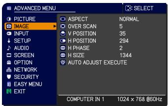
text_image
ADVANCED MENU PICTURE IMAGE INPUT SETUP AUDIO SCREEN OPTION NETWORK SECURITY EASY MENU EXIT ASPECT NORMAL OVER SCAN 5 V POSITION 35 H POSITION 294 H PHASE 2 H SIZE 1344 AUTO ADJUST EXECUTE COMPUTER IN 1 1024 x 768 @60Hz| Item | Description |
| ASPECT | Using the ▲/▼ buttons switches the mode for aspect ratio.For a computer signalNORMAL ⇔ 4:3 ⇔ 16:9 ⇔ 16:10For an HDMITM signalNORMAL ⇔ 4:3 ⇔ 16:9 ⇔ 16:10 ⇔ 14:9For a video signal, s-video signal or component video signal4:3 ⇔ 16:9 ⇔ 14:9For an input signal from the LAN, USB TYPE A or USB TYPE B port, or if there is no signal• The NORMAL mode keeps the original aspect ratio of the signal. |
| OVER SCAN | Using the ◀/► buttons adjusts the over-scan ratio.Small (It magnifies picture) ⇔ Large (It reduces picture)• This item can be selected only for a video, s-video and component video signal.• For an HDMITM signal, this item can also be selected if either (1) or (2) applies.(1) HDMI FORMAT item in the INPUT menu is set to VIDEO.(2) HDMI FORMAT item in the INPUT menu is set to AUTO, and the projector recognizes that it receives video signals. |
(continued on next page)
| Item | Description |
| V POSITION | Using the ◀/▶ buttons adjusts the vertical position. Down ⇔ UpOver-adjusting the vertical position may cause noise to appear on the screen. If this occurs, please reset the vertical position to the default setting. Pressing the RESET button when the V POSITION is selected will reset the V POSITION to the default setting.When this function is performed on a video signal or an s-video signal, the range of this adjustment depends on OVER SCAN setting. It is not possible to adjust when OVER SCAN is set to 10.This function is unavailable for a signal from the LAN, USB TYPE A, USB TYPE B or HDMI port. |
| H POSITION | Using the ◀/▶ buttons adjusts the horizontal position. Right ⇔ LeftOver-adjusting the horizontal position may cause noise to appear on the screen. If this occurs, please reset the horizontal position to the default setting. Pressing the RESET button when the H POSITION is selected will reset the H POSITION to the default setting.When this function is performed on a video signal or an s-video signal, the range of this adjustment depends on OVER SCAN setting. It is not possible to adjust when OVER SCAN is set to 10.This function is unavailable for a signal from the LAN, USB TYPE A, USB TYPE B or HDMI port. |
(continued on next page)
| Item | Description |
| H PHASE | Using the ◀/► buttons adjusts the horizontal phase to eliminate flicker.Right ⇔ LeftThis item can be selected only for a computer signal or a component video signal. This function is unavailable for a signal from the LAN, USB TYPE A, USB TYPE B or HDMI port. |
| H SIZE | Using the ◀/► buttons adjusts the horizontal size.Small ⇔ LargeThis item can be selected only for a computer signal. This function is unavailable for a signal from the LAN, USB TYPE A, USB TYPE B or HDMI port.When this adjustment is excessive, the picture may not be displayed correctly. In such a case, please reset the adjustment by pressing the RESET button on the remote control during this operation.Images might appear degraded when this function is operated, but it is not a malfunction. |
| AUTO ADJUST EXECUTE | Selecting this item performs the automatic adjustment feature.For a computer signalThe vertical position, the horizontal position and the horizontal phase will be automatically adjusted.Make sure that the application window is set to its maximum size prior to attempting to use this feature. A dark picture may still be incorrectly adjusted. Use a bright picture when adjusting.For a video signal and s-video signalThe video format best suited for the respective input signal will be selected automatically. This function is available only when the AUTO is selected for the VIDEO FORMAT item in the INPUT menu. The vertical position and horizontal position will be automatically set to the default.For a component video signalThe vertical position and horizontal position will be automatically set to the default. The horizontal phase will be automatically adjusted.The automatic adjustment operation requires approx. 10 seconds. Also please note that it may not function correctly with some input.When this function is performed for a video signal, a certain extra such as a line may appear outside a picture.When this function is performed for a computer signal, a black frame may be displayed on the edge of the screen, depending on the PC model.The items adjusted by this function may vary when the FINE or DISABLE is selected for the AUTO ADJUST item of the SERVICE item in the OPTION menu. |
INPUT menu
From the INPUT menu, items shown in the table below can be performed.
Select an item using the ▲/▼ cursor buttons, and press the ▶ cursor button or ENTER button to execute the item. Then perform it according to the following table.
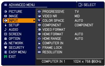
text_image
ADANCED MENU PICTURE IMAGE INPUT SETUP AUDIO SCREEN OPTION NETWORK SECURITY EASY MENU EXIT PROGRESSIVE TV VIDEO NR MID COLOR SPACE AUTO COMPONENT COMPONENT VIDEO FORMAT HDMI FORMAT AUTO HDMI RANGE AUTO COMPUTER IN FRAME LOCK RESOLUTION COMPUTER IN 1 1024 x 768 @60Hz| Item | Description |
| PROGRESSIVE | Using the ▲/▼ buttons switches the progress mode.TV ⇔ FILM ⇔ OFFThis function works only for a video signal, s-video signal, component video signal (of 480i@60 or 576i@50 or 1080i@50/60) and an HDMITMsignal (of 480i@60 or 576i@50 or 1080i@50/60).When TV or FILM is selected, the screen image will be sharp. FILM adapts to the 2-3 Pull-Down conversion system. But these may cause a certain defect (for example, jagged line) of the picture for a quick moving object. In such a case, please select OFF, even though the screen image may lose sharpness. |
| VIDEO NR | Using the ▲/▼ buttons switches the noise reduction mode.HIGH ⇔ MID ⇔ LOWThis function works only for a video signal, s-video signal, component video signal (of 480i@60 or 576i@50 or 1080i@50/60) and an HDMITM signal (of 480i@60 or 576i@50 or 1080i@50/60). |
| COLOR SPACE | Using the ▲/▼ buttons switches the mode for color space.AUTO ⇔ RGB ⇔ SMPTE240 ⇔ REC709 ⇔ REC601This item can be selected only for a computer signal (except for signals from the LAN, USB TYPE A and USB TYPE B ports) or a component video signal (except SCART RGB).The AUTO mode automatically selects the optimum mode.The AUTO operation may not work well at some signals. In such a case, it might be good to select a suitable mode except AUTO. |
| COMPONENT | Using the ▲/▼ buttons switches the function of the COMPONENT ports.COMPONENT ⇔ SCART RGBWhen the SCART RGB is selected, the COMPONENT (Y, Cb/Pb, Cr/Pr) and VIDEO ports will function as a SCART RGB port. A SCART adapter or SCART cable is required for a SCART RGB input to the projector. For details, contact your dealer. |
(continued on next page)
| Item | Description | |
| VIDEO FORMAT | The video format for S-VIDEO port and VIDEO port can be set.(1) Use the ▲/▼ buttons to select the input port.(2) Using the ◀/► buttons switches the mode for video format.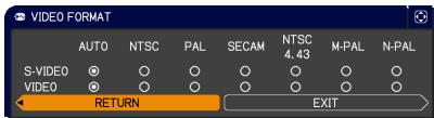 AUTO ⇔ NTSC ⇔ PAL ⇔ SECAMN-PAL ⇔ M-PAL ⇔ NTSC4.43 ↗This item is performed only for a video signal from theVIDEO port or theS-VIDEO port.The AUTO mode automatically selects the optimum mode.The AUTO operation may not work well for some signals. If the picture becomes unstable (e.g. an irregular picture, lack of color), please select the mode according to the input signal. AUTO ⇔ NTSC ⇔ PAL ⇔ SECAMN-PAL ⇔ M-PAL ⇔ NTSC4.43 ↗This item is performed only for a video signal from theVIDEO port or theS-VIDEO port.The AUTO mode automatically selects the optimum mode.The AUTO operation may not work well for some signals. If the picture becomes unstable (e.g. an irregular picture, lack of color), please select the mode according to the input signal. | |
| HDMI FORMAT | Using the ▲/▼ cursor buttons switches the video format for an input from theHDMI port.AUTO ⇔ VIDEO ⇔ COMPUTER↑ | |
| Feature | ||
| AUTO | automatically sets the optimum mode. | |
| VIDEO | sets the suitable mode for DVD signals. | |
| COMPUTER | sets the suitable mode for computer signals. | |
| When the COMPUTER is selected, the functions COLOR (PICTURE menu), TINT (PICTURE menu) and OVER SCAN (IMAGE menu) are unavailable. | ||
| HDMI RANGE | Using the ▲/▼ cursor buttons changes the digital range for input from theHDMI port.AUTO ⇔ NORMAL ⇔ ENHANCED↑ | |
| Feature | ||
| AUTO | automatically sets the optimum mode. | |
| NORMAL | sets the suitable mode for DVD signals. (16-235) | |
| ENHANCED | sets the suitable mode for computer signals. (0-255) | |
| If the contrast of the screen image is too strong or too weak, try finding a more suitable mode. | ||
(continued on next page)
| Item | Description |
| COMPUTER IN | The computer input signal type for COMPUTER IN1 and IN2 ports can be set.(1) Use the ▲/▼ buttons to select the COMPUTER IN port to be set.(2) Use the ◀/► buttons to select the computer input signal type. AUTO ⇔ SYNC ON G OFF 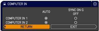 • Selecting the AUTO mode allows you to input a sync on G signal or component video signal from the port.• In the AUTO mode, the picture may be distorted with certain input signals. In such a case, remove the signal connector so that no signal is received and select the SYNC ON G OFF, and then reconnect the signal. • Selecting the AUTO mode allows you to input a sync on G signal or component video signal from the port.• In the AUTO mode, the picture may be distorted with certain input signals. In such a case, remove the signal connector so that no signal is received and select the SYNC ON G OFF, and then reconnect the signal. |
| FRAME LOCK | Set the frame lock function on/off for each port.(1) Use the ▲/▼ buttons to select the input ports.(2) Use the ◀/► buttons to turn the frame lock function on/off . ON ⇔ OFF 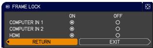 • This item can be performed only on a signal with a vertical frequency of 49 to 51Hz, 59 to 61 Hz.• When ON is selected, moving pictures are displayed more smoothly. • This item can be performed only on a signal with a vertical frequency of 49 to 51Hz, 59 to 61 Hz.• When ON is selected, moving pictures are displayed more smoothly. |
(continued on next page)
| Item | Description |
| RESOLUTION | The resolution for the COMPUTER IN1 and COMPUTER IN2 input signals can be set on this projector.(1) In the INPUT menu select the RESOLUTION using the ▲/▼ buttons and press the ▶ button.The RESOLUTION menu will be displayed.(2) In the RESOLUTION menu select the resolution you wish to display using the ▲/▼ buttons.Selecting AUTO will set a resolution appropriate to the input signal.(3) Pressing the ▶ or ENTER button when selecting a STANDARD resolution will automatically adjust the horizontal and vertical positions, clock phase and horizontal size.The INPUT_INFORMATION dialog will be displayed.(4) To set a custom resolution use the ▲/▼ buttons to select the CUSTOM and the RESOLUTION_CUSTOM box will be displayed.Set the horizontal (HORZ) and vertical (VERT) resolutions using the ▲/▼/◄/► buttons.This function may not support all resolutions.(5) Move the cursor to OK on screen and press the ▶ or ENTER button. The message "ARE YOU SURE YOU WISH TO CHANGE RESOLUTION?" appears. To save the setting, press the ▶ button.The horizontal and vertical positions, clock phase and horizontal size will be automatically adjusted.The INPUT_INFORMATION dialog will be displayed.(6) To revert back to the previous resolution without saving changes, move the cursor to CANCEL on screen and press the ◀ or ENTER button.The screen will then return to the RESOLUTION menu displaying the previous resolution.• For some pictures, this function may not work well. |
SETUP menu
From the SETUP menu, items shown in the table below can be performed.
Select an item using the ▲/▼ cursor buttons, and press the ▶ cursor button or ENTER button to execute the item. Then perform it according to the following table.
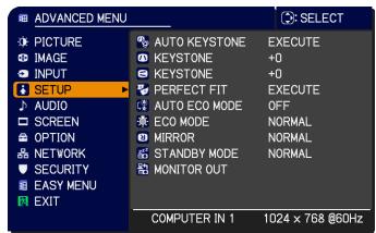
text_image
ADVANCED MENU PICTURE IMAGE INPUT SETUP AUDIO SCREEN OPTION NETWORK SECURITY EASY MENU EXIT AUTO KEYSTONE EXECUTE KEystone +0 KEYSTONE +0 PERFECT FIT EXECUTE AUTO ECO MODE OFF ECO MODE NORMAL MIRROR NORMAL STANDBY MODE NORMAL MONITOR OUT COMPUTER IN 1 1024 x 768 @60Hz| Item | Description |
| AUTO KEYSTONE | Selecting this item performs the Automatic keystone distortion correction. Projector automatically corrects vertical keystone distortion due to the (forward/backward) setup angle by itself. This function will be executed only once when selected in the menu. When the slant of the projector is changed, execute this function again.The adjustable range of this function will vary among inputs. For some input, this function may not work well.When V:INVERT or H&V:INVERT is selected to the MIRROR item in the SETUP menu, if the projector screen is inclined or angled downward, this function may not work correctly.When the zoom adjustment is set to the TELE (telephoto focus), this function may be excessive. This function should be used when the zoom adjustment is set to the full WIDE (wide-angle focus) whenever possible.When the projector is placed on the level (about ± 4^ ), this function may not work.When the projector is inclined to near ± 30 degree or over, this function may not work well.This function is unavailable when the TRANSITION DETECTOR is ON or the screen is adjusted by PERFECT FIT. |
| KEYSTONE | Using the ◀/► buttons corrects the vertical keystone distortion.Shrink the bottom of the image ⇔ Shrink the top of the imageThe adjustable range of this function will vary among inputs. For some input, this function may not work well.When the zoom adjustment is set to the TELE (telephoto focus), this function may be excessive. This function should be used when the zoom adjustment is set to the full WIDE (wide-angle focus) whenever possible.This function is unavailable when the TRANSITION DETECTOR is ON or the screen is adjusted by PERFECT FIT. |
(continued on next page)
| Item | Description |
| [2022] KEYSTONE | Using the ◀/▶ buttons corrects the horizontal keystone distortion. Shrink the right of the image ⇔ Shrink the left of the image• The adjustable range of this function will vary among inputs. For some input, this function may not work well.• When the horizontal lens shift is not set to the center, this function may not work well.• This function is unavailable when the TRANSITION DETECTOR is ON or the screen is adjusted by PERFECT FIT. |
| PERFECT FIT | Selecting this item displays the KEYSTONE_PERFECT FIT dialog. For details, see PERFECT FIT in Correcting the distortion.• This is unavailable when the TRANSITION DETECTOR is ON. |
| AUTO ECO MODE | Using the ▲/▼ buttons turns on/off the AUTO ECO MODE.ON ⇔ OFF• When ON is selected, the projector will always be set to Eco mode at start-up regardless of the ECO MODE setting. An OSD message “AUTO ECO MODE” will be displayed for tens of seconds when the projector starts with this function activated. |
| ECO MODE | Using the ▲/▼ buttons turns off/on the Eco mode.NORMAL ⇔ ECO• When the ECO is selected, acoustic noise and screen brightness are reduced.• When AUTO ECO MODE is set to ON, the projector will always be set to Eco mode at start-up regardless this setting. |
| MIRROR | Using the ▲/▼ buttons switches the mode for mirror status.    NORMAL ⇔ H:INVERT ⇔ V:INVERT ⇔ H&V:INVERTIf the Transition Detector is on and MIRROR status is changed, TRANSITION DETECTOR ON alarm will be displayed when projector is restarted after the AC power is turned off. NORMAL ⇔ H:INVERT ⇔ V:INVERT ⇔ H&V:INVERTIf the Transition Detector is on and MIRROR status is changed, TRANSITION DETECTOR ON alarm will be displayed when projector is restarted after the AC power is turned off. |
(continued on next page)
| Item | Description |
| STANDBY MODE | Using ▲/▼ buttons switches the standby mode setting between NORMAL and SAVING.NORMAL ⇔ SAVINGWhen SAVING is selected, the power consumption in the standby mode is lowered with some functional restriction as below:When SAVING is selected, the RS-232C communication control except to turn the projector on and the network function are disabled while the projector is in the standby mode. If the COMMUNICATION TYPE in the COMMUNICATION menu is set to NETWORK BRIDGE, all of the RS-232C commands are disabled.When SAVING is selected, STANDBY setting of AUDIO SOURCE is invalid, and no signal is output fromAUDIO OUTport in the standby mode.When SAVING is selected, STANDBY setting of MONITOR OUT is invalid, and no signal is output fromMONITOR OUTport in the standby mode. |
| MONITOR OUT | While the image signal from the input port chosen in step (1) is projected, the image signal from the input port selected in step (2) is output toMONITOR OUTport.(1) Choose a picture input port using ▲/▼ buttons.Choose STANDBY to select the picture output in the standby mode.(2) Select one of theCOMPUTER IN ports using◄/►buttons.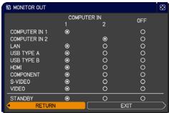 Select OFF to disable theMONITOR OUT port for the input port or standby mode chosen in the step (1).You cannot selectCOMPUTER IN1in step (1) andCOMPUTER IN2in step (2) and vice versa. Select OFF to disable theMONITOR OUT port for the input port or standby mode chosen in the step (1).You cannot selectCOMPUTER IN1in step (1) andCOMPUTER IN2in step (2) and vice versa. |
AUDIO menu
From the AUDIO menu, items shown in the table below can be performed. Select an item using the ▲/▼ cursor buttons, and press the ▶ cursor button or the ENTER button to execute the item. Then perform it according to the following table.
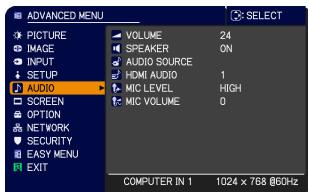
text_image
ADVANCED MENU PICTURE IMAGE INPUT SETUP AUDIO SCREEN OPTION NETWORK SECURITY EASY MENU EXIT VOLUME 24 SPEAKER ON AUDIO SOURCE HDMI AUDIO 1 MIC LEVEL HIGH MIC VOLUME 0 COMPUTER IN 1 1024 x 768 @60Hz| Item | Description |
| VOLUME | Using the ◀/► buttons adjusts the volume.Low ⇔ High |
| SPEAKER | Using the ▲/▼ buttons turns on/off the built-in speaker.ON ⇔ OFFWhen OFF is selected, the built-in speaker does not work. |
| AUDIO SOURCE | While the image signal from the input port chosen in step (1) is projected, the audio signal from the input port selected in step (2) is output to both theAUDIO OUTport and built-in speaker of this projector. However, the built-in speaker does not work when SPEAKER is set to OFF.(1) Choose a picture input port using the▲/▼ buttons.Choose STANDBY to select the sound output in the standby mode.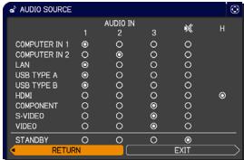 (2) Select one of theAUDIO INports using◄/► buttons.Select ≈ to mute the sound from the input port or in the standby mode chosen in the step (1).• In the AUDIO SOURCE window, “H” symbolizes the audio signal from theHDMIport. It can be selected only for the picture input from theHDMIport.• Even if the projector is in the standby mode, cooling fans may work and make noises when the built-in speaker is in operation.• C.C. (Closed Caption) is automatically activated when ≈ is selected and an input signal containing C.C. is received. This function is available only when the signal is NTSC forVIDEOorS-VIDEO, or 480i@60 forCOMPONENT, COMPUTER IN1or COMPUTER IN2, and when AUTO is selected for DISPLAY in the C.C. menu under the SCREEN menu. (2) Select one of theAUDIO INports using◄/► buttons.Select ≈ to mute the sound from the input port or in the standby mode chosen in the step (1).• In the AUDIO SOURCE window, “H” symbolizes the audio signal from theHDMIport. It can be selected only for the picture input from theHDMIport.• Even if the projector is in the standby mode, cooling fans may work and make noises when the built-in speaker is in operation.• C.C. (Closed Caption) is automatically activated when ≈ is selected and an input signal containing C.C. is received. This function is available only when the signal is NTSC forVIDEOorS-VIDEO, or 480i@60 forCOMPONENT, COMPUTER IN1or COMPUTER IN2, and when AUTO is selected for DISPLAY in the C.C. menu under the SCREEN menu. |
(continued on next page)
| Item | Description |
| HDMI AUDIO | Using the ▲/▼ buttons switches the mode for the HDMITM audio.Check each of the two modes provided and select the suitable one for your HDMITM audio device.1 ⇔ 2 |
| MIC LEVEL | Using the ▲/▼ buttons switches the input level to match that of the microphone connected to the MIC port.HIGH ⇔ LOWHIGH: for a microphone with an amplifier.LOW: for a microphone without an amplifier. |
| MIC VOLUME | Using the ◀/► buttons adjusts the volume of the microphone connected to the MIC port.Low ⇔ High |
SCREEN menu
From the SCREEN menu, items shown in the table below can be performed.
Select an item using the ▲/▼ cursor buttons, and press the ▶ cursor button or ENTER button to execute the item. Then perform it according to the following table.
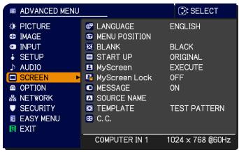
text_image
ADANCED MENU PICTURE IMAGE INPUT SETUP AUDIO SCREEN OPTION NETWORK SECURITY EASY MENU EXIT LANGUAGE MENU POSITION BLANK START UP MyScreen MyScreen Lock MESSAGE SOURCE NAME TEMPLATE C.C. SELECT ENGLISH BLACK ORIGINAL EXECUTE OFF ON TEST PATTERN COMPUTER IN 1 1024 x 768 @60Hz| Item | Description |
| LANGUAGE | Using the ▲/▼/◄/► buttons switches the OSD (On Screen Display) language.ENGLISH ⇔ FRANÇAIS ⇔ DEUTSCH ⇔ ESPAÑOL↑---- (shown in the LANGUAGE dialog) ...... ↑Press the ENTER or INPUT button to save the language setting. |
| MENU POSITION | Using the ▲/▼/◄/► buttons adjusts the menu position.To quit the operation, press the MENU button on the remote control or keep no operation for about 10 seconds. |
| BLANK | Using the ▲/▼ buttons switches the mode for the blank screen.The blank screen is a screen for the temporarily blanking feature. It is displayed by pressing the BLANK button on the remote control.MyScreen ⇔ ORIGINAL ⇔ BLUE ⇔ WHITE ⇔ BLACK↑MyScreen : Screen can be registered by the MyScreen item.ORIGINAL : Screen preset as the standard screen.BLUE, WHITE, BLACK : Plain screens in each color.• To avoid remaining as an afterimage, the MyScreen or ORIGINAL screen will change to the plain black screen after several minutes. |
| START UP | Using the ▲/▼ buttons switches the mode for the start-up screen.The start-up screen is a screen displayed when no signal or an unsuitable signal is detected.MyScreen ⇔ ORIGINAL ⇔ OFF↑MyScreen : Screen can be registered by the MyScreen item.ORIGINAL : Screen preset as the standard screen.OFF : Plain black screen.• To avoid remaining as an afterimage, the MyScreen or ORIGINAL screen will change to the BLANK screen after several minutes. If also the BLANK screen is the MyScreen or ORIGINAL, the plain black screen is instead used.• When the ON is selected to the MyScreen PASSWORD item in the SECURITY menu, the START UP is fixed to MyScreen. |
(continued on next page)
| Item | Description |
| MyScreen | This item allows you to capture an image for use as a MyScreen image which can be used as the BLANK screen and START UP screen. Display the image you want to capture before executing the following procedure.1. Selecting this item displays a dialog titled “MyScreen”. It will ask you if  you start capturing an image from the current screen.Please wait for the target image to be displayed, and press the ENTER or INPUT button when the image is displayed. The image will freeze and the frame for capturing will appear.To stop performing, press the RESET button on the remote control.2. Using the ▲/▼/◄/► buttons adjusts the frame position.Please move the frame to the position of the image which you want to use. The frame may not be able to be moved for some input signals.To start registration, press the ENTER or INPUT button on the remote control.To restore the screen and return to the previous dialog, press the RESET button on the remote control.Registration may take several minutes.When the registration is completed, the registered screen and the following message is displayed for several seconds:“MyScreen registration is finished.”If the registration failed, the following message is displayed:“A capturing error has occurred. Please try again.”This function cannot be selected when the ON is selected to the MyScreen Lock item.This function cannot be selected when the ON is selected to the MyScreen PASSWORD item in SECURITY menu.This function is unavailable for a signal from the LAN, USB TYPE A, USB TYPE B or HDMI port. you start capturing an image from the current screen.Please wait for the target image to be displayed, and press the ENTER or INPUT button when the image is displayed. The image will freeze and the frame for capturing will appear.To stop performing, press the RESET button on the remote control.2. Using the ▲/▼/◄/► buttons adjusts the frame position.Please move the frame to the position of the image which you want to use. The frame may not be able to be moved for some input signals.To start registration, press the ENTER or INPUT button on the remote control.To restore the screen and return to the previous dialog, press the RESET button on the remote control.Registration may take several minutes.When the registration is completed, the registered screen and the following message is displayed for several seconds:“MyScreen registration is finished.”If the registration failed, the following message is displayed:“A capturing error has occurred. Please try again.”This function cannot be selected when the ON is selected to the MyScreen Lock item.This function cannot be selected when the ON is selected to the MyScreen PASSWORD item in SECURITY menu.This function is unavailable for a signal from the LAN, USB TYPE A, USB TYPE B or HDMI port. |
(continued on next page)
| Item | Description |
| MyScreen Lock | Using the ▲/▼ buttons turns on/off the MyScreen lock function.ON ⇔ OFFWhen the ON is selected, the item MyScreen is locked. Use this function for protecting the current MyScreen.This function cannot be selected when the ON is selected to the MyScreen PASSWORD item in SECURITY menu. |
| MESSAGE | Using the ▲/▼ buttons turns on/off the message function.ON ⇔ OFFWhen the ON is selected, the following message function works.“AUTO IN PROGRESS” while automatically adjusting“NO INPUT IS DETECTED”“SYNC IS OUT OF RANGE”“INVALID SCAN FREQ.”“Searching....” while searching for the input“Detecting....” while an input signal is detected“AUTO ECO MODE” while starting up with AUTO ECO MODEThe indication of the input signal displayed by changingThe indication of the aspect ratio displayed by changingThe indication of the PICTURE MODE displayed by changingThe indication of the ACTIVE IRIS displayed by changingThe indication of the MY MEMORY displayed by changingThe indication of “FREEZE” and “II” while freezing the screen by pressing the FREEZE button.The indication of the TEMPLATE displayed by changing.When the OFF is selected, please remember if the picture is frozen. Do not mistake freezing for a malfunction. |
(continued on next page)
| Item | Description | |
| SOURCE NAME | Each input port for this projector can have a name applied to it.(1) Use the ▲/▼ buttons on the SCREEN menu to select SOURCE NAME and press the ▶ or ENTER button.The SOURCE NAME menu will be displayed.(2) Use the ▲/▼ buttons on the SOURCE NAME menu to select the port to be named and press the ▶ button. The SOURCE NAME dialog will be displayed.Right side of the menu is blank until a name is specified.(3) Select an icon you would like to assign to the port in the SOURCE NAME dialog.The name assigned to the port will also be automatically switched according to your icon selection. Press the ENTER or INPUT button to determine your icon selection.(4) Select a number you would like to assign to the port along with the icon. You can select the number either from blank (no number assigned), 1, 2, 3, or 4.Then press the ENTER or INPUT button.(5) If you would like to modify the name assigned to the port, select CUSTOM NAME and press the ENTER or INPUT button. | 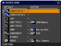 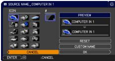 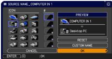 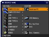 |
(continued on next page)
| Item | Description |
| SOURCE NAME(Continued) | (6) The current name will be displayed on the first line. Use the ▲/▼/◄/► buttons and the ENTER or INPUT button to select and enter characters. To erase 1 character at one time, press the RESET button or press the ◀ and INPUT button at the same time. Also if you move the cursor to DELETE or ALL CLEAR on screen and press the ENTER or INPUT button, 1 character or all characters will be erased. The name can be a maximum of 16 characters.(7) To change an already inserted character, press the ▲ button to move the cursor to the first line, and use the ◀/► buttons to move the cursor on the character to be changed.After pressing the ENTER or INPUT button, the character is selected. Then, follow the same procedure as described at the item (6) above.(8) To finish entering text, move the cursor to the OK on screen and press the ►, ENTER or INPUT button. To revert to the previous name without saving changes, move the cursor to the CANCEL on screen and press the ◀, ENTER or INPUT button. |
| TEMPLATE | Using the ▲/▼ cursor buttons switches the mode for the template screen.Press the ► cursor (or the ENTER) button to display the selected template, and press the ◀ cursor button to close the displayed screen.The last selected template is displayed when the MY BUTTON allocated to the TEMPLATE function is pressed.TEST PATTERN ⇔ DOT-LINE1 ⇔ DOT-LINE2 ⇔ DOT-LINE3 ↑↓ ↑↓STACK ⇔ MAP2 ⇔ MAP1 ⇔ CIRCLE2 ⇔ CIRCLE1 ⇔ DOT-LINE4 You can turn a map upside down and scroll it horizontally when MAP1 or MAP2 is selected. To invert or scroll the map, display the guidance by pressing the RESET button on the remote three seconds or more when MAP1 or MAP2 appears. |
(continued on next page)
| Item | Description |
| C.C.(Closed Caption) | The C.C. is the function that displays a transcript or dialog of the audio portion of a video, files or other presentation or other relevant sounds. It is required to have NTSC format video or 480i@60 format component video source supporting C.C. feature to utilize this function.It may not work properly, depending on equipment or signal source. In this case, please turn off the Closed Caption. |
| DISPLAYSelect Closed Caption DISPLAY setting from following options using ▲/▼ buttons.AUTO ⇔ ON ⇔ OFFAUTO : Closed Caption automatically displays when the volume is muted.ON : Closed Caption is on.OFF : Closed Caption is off.The caption is not displayed when the OSD menu is active.The Closed Caption is the function to display the dialogue, narration, and / or sound effects of a television program or other video sources. The Closed Caption availability is depending upon broadcaster and/or content. | |
| MODESelect Closed Caption MODE setting from following options using ▲/▼ buttons.CAPTIONS ⇔ TEXTCAPTIONS : Display Closed Caption.TEXT : Display Text data, which is for additional information such as news reports or a TV program guide. The information covers the entire screen. Not all of the C.C. program has Text information. | |
| CHANNELSelect Closed Caption CHANNEL from following options using ▲/▼ buttons.1 ⇔ 2 ⇔ 3 ⇔ 41: Channel 1, primary channel / language2: Channel 23: Channel 34: Channel 4The channel data may vary, depending on the content. Some channel might be used for secondary language or empty. |
OPTION menu
From the OPTION menu, items shown in the table below can be performed.
Select an item using the ▲/▼ cursor buttons, and press the ▶ cursor button or ENTER button to execute the item, except for the items LAMP TIME and FILTER TIME. Then perform it according to the following table.
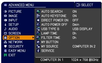
text_image
ADVANCED MENU TITLE PICTURE IMAGE INPUT SETUP AUDIO SCREEN OPTION NETWORK SECURITY EASY MENU EXIT AUTO SEARCH ON AUTO KEYSTONE ON DIRECT POWER ON OFF AUTO POWER OFF 0min USB TYPE B USB DISPLAY LAMP TIME 0h FILTER TIME 0h MY BUTTON MY SOURCE COMPUTER IN 2 SERVICE COMPUTER IN 1 1024 x 768 @60Hz| Item | Description |
| AUTO SEARCH | Using the ▲/▼ buttons turns on/off the automatic signal search function.ON ⇔ OFFWhen the ON is selected, detecting no signal automatically cycles through input ports in the following order. The search is started from the current port. Then when an input is found, the projector will stop searching and display the image.→ COMPUTER IN1 ⇌ COMPUTER IN2 ⇌ LAN ⇌ USB TYPE AVIDEO ⇌ S-VIDEO ⇌ COMPONENT ⇌ HDMI ⇌ USB TYPE B←• It may take several seconds to project the images from theUSB TYPE B port. |
| AUTO KEYSTONE | Using the ▲/▼ buttons turns on/off the automatic keystone function.ON ⇔ OFFON : Automatic keystone distortion correction will be executed whenever changing the slant of the projector.OFF : This function is disabled. Please execute the AUTO KEYSTONE (EXECUTE) in the SETUP menu for automatic keystone distortion correction.When the projector is suspended from the ceiling this feature will not function properly so select the OFF.This function will be unavailable when the Transition Detector is on. |
| DIRECT POWER ON | Using the ▲/▼ buttons turns on/off the DIRECT POWER ON function.ON ⇔ OFFWhen set to the ON, the lamp in projector will be automatically turned on without the usual procedure, only when the projector is supplied with the power after the power was cut while the lamp was on.This function does not work as long as the power has been supplied to the projector while the lamp is off.After turning the lamp on by the DIRECT POWER ON function, if neither input nor operation is detected for about 30 minutes, the projector is turned off, even though the AUTO POWER OFF function is disabled. |
(continued on next page)
| Item | Description |
| AUTO POWER OFF | Using the ▲/▼ buttons adjusts the time to count down to automatically turn the projector off.Long (max. 99 minutes) ⇔ Short (min. 0 minute = DISABLE)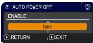 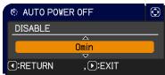 When the time is set to 0, the projector is not turned off automatically.When the time is set to 1 to 99, and when the passed time with no-signal or an unsuitable signal reaches at the set time, the projector lamp will be turned off.If one of the projector's buttons or the remote control buttons is pressed or one of the commands (except get commands) is transmitted to theCONTROL port during the corresponding time, projector will not be turned off.Please refer to the sectionTurning off the power. When the time is set to 0, the projector is not turned off automatically.When the time is set to 1 to 99, and when the passed time with no-signal or an unsuitable signal reaches at the set time, the projector lamp will be turned off.If one of the projector's buttons or the remote control buttons is pressed or one of the commands (except get commands) is transmitted to theCONTROL port during the corresponding time, projector will not be turned off.Please refer to the sectionTurning off the power. |
| USB TYPE B | Using the ▲/▼ buttons selects the function of USB TYPE B port.To use this function, you need to connect the USB TYPE B port of the projector and the type A USB port of a computer.MOUSE ⇔ USB DISPLAYMOUSE: The accessory remote control works as the simple mouse and keyboard of the computer.USB DISPLAY: The port works as an input port that receives image signals from the computer.It may take several seconds to project the images from the USB TYPE B port.In the following cases, a message to notify you that USB TYPE B port is not available for picture input appears together with the USB TYPE B dialog:- This setting is switched to MOUSE while a picture input from the USB TYPE B port is projected.- The USB TYPE B port is selected as the picture input source while this setting is set to MOUSE. Select USB DISPLAY in the dialog to project the picture input to the USB TYPE B port. In this case, you cannot use the simple mouse and keyboard function. Otherwise select other port for picture input. |
(continued on next page)
| Item | Description |
| LAMP TIME | The lamp time is the usage time of the lamp, counted after the last resetting. It is shown in the OPTION menu.Pressing the RESET button on the remote control or the ▶ button of the projector displays a dialog.To reset the lamp time, select the OK using the ▶ button.CANCEL ⇒ OKPlease reset the lamp time only when you have replaced the lamp, for a suitable indication about the lamp.For the lamp replacement, see the sectionReplacing the lamp |
| FILTER TIME | The filter time is the usage time of the air filter, counted after the last resetting. It is shown in the OPTION menu.Pressing the RESET button on the remote control or the ▶ button of the projector displays a dialog.To reset the filter time, select the OK using the ▶ button.CANCEL ⇒ OKPlease reset the filter time only when you have cleaned or replaced the air filter, for a suitable indication about the air filter.For the air filter cleaning, see the sectionCleaning and replacing the air filter. |
(continued on next page)
| Item | Description |
| MY BUTTON | This item is to assign one of the following functions to MY BUTTON 1/2 on the remote control.(1) Use the ▲/▼ buttons on the MY BUTTON menu to select a MY BUTTON - (1/2) and press the ▶ or ENTER button to display the MY BUTTON setup dialog.(2) Then using the ▲/▼/◄/► buttons sets one of the following functions to the chosen button. Press the ENTER or INPUT button to save the setting.LAN: Selects input from LAN port.USB TYPE A: Selects input from USB TYPE A port.USB TYPE B: Selects input from USB TYPE B port.HDMI: Selects input from HDMI port.COMPUTER IN1: Selects the input from COMPUTER IN1 port.COMPUTER IN2: Selects the input from COMPUTER IN2 port.COMPONENT: Selects the input from COMPONENT ports.S-VIDEO: Selects the input from S-VIDEO port.VIDEO: Selects the input from VIDEO port.SLIDESHOW: Selects the input from USB TYPE A, and starts a Slideshow.MY IMAGE: Displays the MY IMAGE menu.MESSENGER: Turns the messenger text displayed on the screen on/off (5. Messenger Function in the Network Guide).When there is no transferred text data to display, the message "NO MESSENGER DATA" appears.INFORMATION: Displays SYSTEM_INFORMATION, INPUT_INFORMATION, NETWORK_INFORMATION or nothing.AUTO KEYSTONE : Performs automatic keystone distortion correction.MY MEMORY: Loads one of adjustment data stored.When more than one data are saved, the adjustment changes every time the MY BUTTON is pressed.When no data is saved in memory, the dialog "No saved data" appears.When the current adjustment is not saved to memory, the dialog as shown in 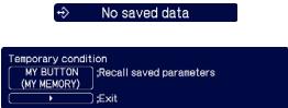 the right appears.If you want to keep the current adjustment, please press the ► button to exit. Otherwise loading a data will overwrite the current adjusted condition. the right appears.If you want to keep the current adjustment, please press the ► button to exit. Otherwise loading a data will overwrite the current adjusted condition. |
(continued on next page)
| Item | Description |
| MY BUTTON(Continued) | ACTIVE IRIS: Changes the active iris mode.PICTURE MODE: Changes the PICTURE MODE.FILTER RESET: Displays the filter time reset confirmation dialogue.TEMPLATE: Makes the template pattern selected to the TEMPLATE item appear or disappear.AV MUTE: Turns the picture and audio on/off.RESOLUTION: Turns on/off the RESOLUTION dialog.MIC VOLUME: Turns on/off the MIC VOLUME dialog.ECO MODE: Turns on/off the ECO MODE dialog. |
| MY SOURCE | Using ▲/▼ buttons selects the picture input port to be selected with pressing theMY SOURCE/DOC.CAMERAbutton on the remote control.You can use this function not only for document cameras but also computers and other equipment.COMPUTER IN1 ⇔ COMPUTER IN2 ⇔ LAN ⇔ USB TYPE A←VIDEO ⇔ S-VIDEO ⇔ COMPONENT ⇔ HDMI ⇔ USB TYPE B← |
(continued on next page)
| Item | Description | |
 | Selecting this item displays the SERVICE menu.Select an item using the ▲/▼ buttons, and press the ► button or the ENTER 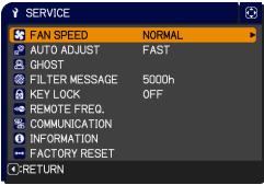 button on the remote control to execute the item. button on the remote control to execute the item. | |
| FAN SPEEDUsing the ▲/▼ buttons switches the rotation speed of the cooling fans. The HIGH is the mode for use at highlands etc. If the projector is used at an altitude of about 1200 m or higher, select HIGH. Otherwise, select NORMAL. Note that the projector is noisier when the HIGH is selected.HIGH ⇔ NORMAL | ||
| AUTO ADJUSTUsing the ▲/▼ buttons to select one of the mode. When the DISABLE is selected, the automatic adjustment feature is disabled.FINE ⇔ FAST ⇔ DISABLEFINE: Finer tuning including H.SIZE adjustment.FAST: Faster tuning, setting H.SIZE to prearranged data for the input signal.Depending on conditions, such as input image, signal cable to the projector, environment around the projector, etc., the automatic adjustment may not work correctly. In such a case, please choose DISABLE to disable the automatic adjustment, and make adjustment manually. | ||
GHOST1. Select a color element of ghost using the ◀/► buttons.2. Adjust the selected element using the ▲/▼ buttons to disappear ghost.  | ||
| FILTER MESSAGEUse the ▲/▼ button to set the timer for notifying by the message when to replace the filter unit100h ⇔ 200h ⇔ 500h ⇔ 1000h ⇔ 2000h ⇔ 5000h ⇔ OFFAfter choosing an item except OFF, the message “REMINDER *** HRS PASSED ....” will appear after the timer reaches the interval time set by this feature.When the OFF is chosen, the message will not appear. Utilize this feature to keep the air filter clean, setting the suitable time according to your environment of this projector.Please take care of the filter unit periodically, even if there is no message. If the air filter becomes to be blocked by dust or other matter, the internal temperature will rise, which could cause malfunction, or reduce the lifetime of the projector.Please be careful with the operating environment of the projector and the condition of the filter unit. | ||
| Item | Description | |
| SERVICE(continued) | KEY LOCK(1) Use the ▲/▼ buttons to choose the operations control.CONTROL PANEL ⇔ REMOTE CONTROL(2) Use the ◀/► buttons to select ON or OFF.ON ⇔ OFFSelecting ON in Step 2 locks the buttons except STANDBY/ON on the operations control selected in Step 1. Selecting OFF releases the locked buttons on the operations control selected in Step 1.· Please use this function to prevent tampering or accidental operation. | |
| REMOTE FREQ.(1) Use the ▲/▼ button to change the projector's remote sensor frequency setting.1:NORMAL ⇔ 2:HIGH(2) Use the ◀/► button to change the projector's remote sensor on or off.ON ⇔ OFFThe factory default setting is for both 1:NORMAL and 2:HIGH to be on. If the remote control does not function correctly, disable either of them.It's not possible to disable both options at the same time. | ||
| COMMUNICATION | Selecting this item displays COMMUNICATION menu.In this menu, you can configure the serial communication settings of the projector using the CONTROL port.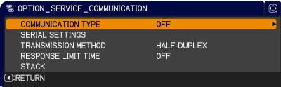 · Select an item using the cursor buttons ▲/▼. Then pressing the ► button opens the submenu for the setting item you selected. Or, pressing the ◀ button instead of the ► button makes the menu back to the previous one without changing the setup. Each submenu can be operated as described above.· When COMMUNICATION TYPE is set to OFF, the other items in COMMUNICATION menu are invalid.· For the function of serial communication, refer to the Network Guide. · Select an item using the cursor buttons ▲/▼. Then pressing the ► button opens the submenu for the setting item you selected. Or, pressing the ◀ button instead of the ► button makes the menu back to the previous one without changing the setup. Each submenu can be operated as described above.· When COMMUNICATION TYPE is set to OFF, the other items in COMMUNICATION menu are invalid.· For the function of serial communication, refer to the Network Guide. | |
(continued on next page)
| Item | Description | |
| SERVICE(continued) | COMMUNICATION(continued) | COMMUNICATION TYPESelect the communication type for transmission via theCONTROL port.NETWORK BRIDGE ⇔ OFFNETWORK BRIDGE: Select this type, if it is required to control an external device as a network terminal, via this projector from the computer.TheCONTROL port doesn't accept RS-232C commands (6. Network Bridge Function in the Network Guide)OFF: Select this mode to receive RS-232C commands using theCONTROL port.OFF is selected as the default setting.When you select the NETWORK BRIDGE, check the item, TRANSMISSTION METHOD. |
| SERIAL SETTINGSSelect the serial communication condition for the CONTROL port.BAUD RATE4800bps ⇔ 9600bps ⇔ 19200bps ⇔ 38400bps↑PARITYNONE ⇔ ODD ⇔ EVENThe BAUD RATE is fixed to 19200bps and PARITY is fixed NONE when the COMMUNICATION TYPE is set to OFF. | ||
| TRANSMISSION METHODSelect the transmission method for communication by the NETWORK BRIDGE from theCONTROL port.HALF-DUPLEX ⇔ FULL-DUPLEXHALF-DUPLEX: This method lets the projector make two way communication, but only one direction, either transmitting or receiving data, is allowed at a time.FULL-DUPLEX: This method lets the projector make two way communication, transmitting and receiving data at the same time.HALF-DUPLEX is selected as the default setting.If you select HALF-DUPLEX, check the setting of the item RESPONSE LIMIT TIME. | ||
(continued on next page)
| Item | Description | |
| SERVICE(continued) | COMMUNICATION(continued) | RESPONSE LIMIT TIMESelect the time period to wait for receiving response data from other device communicating by the NETWORK BRIDGE and the HALF-DUPLEX through theCONTROLport.OFF ⇔ 1s ⇔ 2s ⇔ 3s↑OFF: Select this mode if it is not required to check the responses from the device that the projector sends data to. In this mode, the projector can send out data from the computer continuously.1s /2s /3s: Select the time period to keep the projector waiting for response from the device that the projector sends data to. While waiting the response, the projector does not send out any data from theCONTROLport.This menu is available only when the NETWORK BRIDGE is selected for the COMMUNICATION TYPE and the HALF-DUPLEX is selected for the TRANSMISSION METHOD.OFF is selected as the default setting.STACKSelecting this item displays the STACK menu. For more information, please seeInstant Stack Guide. |
(continued on next page)
| Item | Description |
| SERVICE(continued) | INFORMATIONSelecting this item displays a dialog titled “INPUT_INFORMATION”. It shows the information about the current input.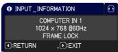  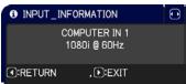 The “FRAME LOCK” message on the dialog means the frame lock function is working.The “SCART RGB” message means the COMPONENT ports is working as a SCART RGB input port. Please refer to the COMPONENT item in INPUT menu.This item can't be selected for no signal and sync out.When the MY TEXT DISPLAY is set to ON, the MY TEXT is displayed together with the input information in the INPUT_INFORMATION box. The “FRAME LOCK” message on the dialog means the frame lock function is working.The “SCART RGB” message means the COMPONENT ports is working as a SCART RGB input port. Please refer to the COMPONENT item in INPUT menu.This item can't be selected for no signal and sync out.When the MY TEXT DISPLAY is set to ON, the MY TEXT is displayed together with the input information in the INPUT_INFORMATION box. |
| FACTORY RESETSelecting OK using the ▶ button performs this function. By this function, all the items in all of menus will collectively return to the initial setting. Note that the items LAMP TIME, FILTER TIME, LANGUAGE, FILTER MESSAGE, NETWORK and SECURITY settings are not reset.CANCEL ⇒ OK |
NETWORK menu
Remember that incorrect network settings on this projector may cause trouble on the network. Be sure to consult with your network administrator before connecting to an existing access point on your network. Select “NETWORK” from the main menu to access the following functions.
Select an item using the ▲/▼ cursor buttons on the projector or remote control, and press the ▶ cursor button on the projector or remote control, or ENTER button on the remote control to execute the item. Then perform it according to the following table.
See the Network Guide for details of NETWORK operation.
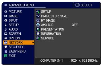
text_image
ADVANCED MENU PICTURE IMAGE INPUT SETUP AUDIO SCREEN OPTION NETWORK SECURITY EASY MENU EXIT SETUP PROJECTOR NAME MY IMAGE AMX D.D. OFF PRESENTATION INFORMATION SERVICE COMPUTER IN 1 1024 x 768 @60HzNOTE • If you are not utilizing SNTP (3.9 Date/Time Settings in the Network Guide), then you must set the DATE AND TIME during the initial installation.
- The network communication control is disabled while the projector is in standby mode if the STANDBY MODE item of SETUP menu is set to SAVING.
Please connect the network communication to the projector after setting the STANDBY MODE to NORMAL.
| Item | Description | |
| SETUP | Selecting this item displays the SETUPMenu for the network.Use the ▲/▼ buttons to select an item,and the ▶ or ENTER button on the remote control to perform the item. 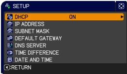 | |
| DHCP (Dynamic Host Configuration Protocol) | Use the ▲/▼ buttons to turn DHCP on/off.ON ⇔ OFFSelect OFF when the network does not have DHCP enabled.When the “DHCP” setting changes to “ON”, it takes a little time to obtain IP address from DHCP server.Auto IP function will be assigned an IP address if the projector could not obtain an IP address from server even if DHCP is “ON”. | |
(continued on next page)
| Item | Description | |
| SETUP(continued) | IP ADDRESS | Use the ▲/▼/◄/► buttons to enter the IP ADDRESS.This function can only be used when DHCP is set to OFF.The IP ADDRESS is the number that identifies this projector on the network. You cannot have two devices with the same IP ADDRESS on the same network.The IP ADDRESS “0.0.0.0” is prohibited. |
| SUBNET MASK | Use the ▲/▼/◄/► buttons to enter the same SUBNET MASK used by your computer.This function can only be used when DHCP is set to OFF.The SUBNET MASK “0.0.0.0” is prohibited. | |
| DEFAULT GATEWAY | Use the ▲/▼/◄/► buttons to enter the DEFAULT GATEWAY (a node on a computer network that serves as an access point to another network) address.This function can only be used when DHCP is set to OFF. | |
| DNS SERVER | Use the ▲/▼/◄/► buttons to input the DNS server address.The DNS server is a system to control domain names and IP addresses on the Network. | |
| TIME DIFFERENCE | Use the ▲/▼ buttons to enter the TIME DIFFERENCE.Set the same TIME DIFFERENCE as the one set on your computer. If unsure, consult your IT manager.Use the ► button to return to the menu after setting the TIME DIFFERENCE. | |
| DATE AND TIME | Use the ▲/▼/◄/► buttons to enter the Year (last two digits), Month, Date, Hour and Minute.The projector will override this setting and retrieve DATE AND TIME information from the Time server when SNTP is enabled. (3.9 Date/Time Settings in the Network Guide) | |
(continued on next page)
| Item | Description |
| PROJECTOR NAME | (1) Use the ▲/▼ buttons on the NETWORK menu to select the PROJECTOR NAME and press the ▶ button. The PROJECTOR NAME dialog will be displayed.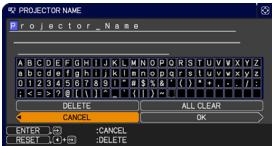 (2) The current PROJECTOR NAME will be displayed on the first 3 lines. Particular projector name is pre-assigned by default.Use the ▲/▼/◄/► buttons and the ENTER or INPUT button to select and enter characters.To erase 1 character at one time, press the RESET button or press the ◀ and INPUT button at the same time. Also if you move the cursor to DELETE or ALL CLEAR on screen and push the ENTER or INPUT button, 1 character or all characters will be erased.The PROJECTOR NAME can be input up to 64 characters.(3) To change an already inserted character, press the ▲/▼ button to move the cursor to one of the first 3 lines, and use the ◀/► buttons to move the cursor on the character to be changed. After pressing the ENTER or INPUT button, the character is selected.Then, follow the same procedure as described at the item (2) above. (2) The current PROJECTOR NAME will be displayed on the first 3 lines. Particular projector name is pre-assigned by default.Use the ▲/▼/◄/► buttons and the ENTER or INPUT button to select and enter characters.To erase 1 character at one time, press the RESET button or press the ◀ and INPUT button at the same time. Also if you move the cursor to DELETE or ALL CLEAR on screen and push the ENTER or INPUT button, 1 character or all characters will be erased.The PROJECTOR NAME can be input up to 64 characters.(3) To change an already inserted character, press the ▲/▼ button to move the cursor to one of the first 3 lines, and use the ◀/► buttons to move the cursor on the character to be changed. After pressing the ENTER or INPUT button, the character is selected.Then, follow the same procedure as described at the item (2) above.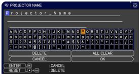 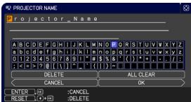 (4) To finish entering text, move the cursor to the OK on screen and press the ►, ENTER or INPUT button. To revert to the previous PROJECTOR NAME without saving changes, move the cursor to the CANCEL on screen and press the ◀, ENTER or INPUT button. (4) To finish entering text, move the cursor to the OK on screen and press the ►, ENTER or INPUT button. To revert to the previous PROJECTOR NAME without saving changes, move the cursor to the CANCEL on screen and press the ◀, ENTER or INPUT button. |
(continued on next page)
| Item | Description |
| MY IMAGE | Selecting this item displays the MY IMAGE menu.To store images in the projector, the application software 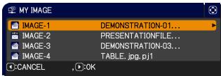 Image Tool that can be downloaded from our website is required.Use the ▲/▼ buttons to select an item which is a still image by the MY IMAGE (4. My Image Function in the Network Guide) and the ▶ or ENTER button to display the image.The item without image stored cannot be selected.The image names are each displayed in 16 characters or less.To switch the image displayedUse the ▲/▼ buttons.To return to the menuPress the ◀ button on the remote control.To erase the image displayed and its source file in the projector.(1) Press the RESET button on the remote control while displaying an image to display the MY IMAGE DELETE menu. Image Tool that can be downloaded from our website is required.Use the ▲/▼ buttons to select an item which is a still image by the MY IMAGE (4. My Image Function in the Network Guide) and the ▶ or ENTER button to display the image.The item without image stored cannot be selected.The image names are each displayed in 16 characters or less.To switch the image displayedUse the ▲/▼ buttons.To return to the menuPress the ◀ button on the remote control.To erase the image displayed and its source file in the projector.(1) Press the RESET button on the remote control while displaying an image to display the MY IMAGE DELETE menu. (2) Press the ▶ button to perform to erase.To stop erasing, press the ◀ button. (2) Press the ▶ button to perform to erase.To stop erasing, press the ◀ button. |
| AMX D.D.(AMX Device Discovery) | Use the ▲/▼ buttons to turn the AMX Device Discovery on/off.ON ⇔ OFFWhen ON is selected, the projector can be detected by controllers of AMX connected to the same network. For the details of AMX Device Discovery, visit the AMX web site.URL: http://www.amx.com/ (as of Aug. 2010) |
(continued on next page)
| Item | Description | |
| PRESENTATION | Selecting this item displays the PRESENTATION menu.Use ▲/▼ buttons to select one of the following items, then press ► or ENTER button to use the function. | |
| QUIT PRESENTER MODE | If you set a computer to the Presenter mode while its image is projected, the projector is occupied by the computer and access from any other computer is blocked.Use this function to quit the Presenter mode and allow other computers to access the projector.Select this item to display a dialog.Press ► button to choose OK in the dialog.The Presenter mode is cancelled and a message is displayed indicating the result.To make Presenter mode setting, use “LiveViewer”. For details, see the section 2.2.2 Presenter mode in the Network Guide. | |
| MULTI PC MODE | If you set one or more computers to the Multi PC mode on “LiveViewer” and send their images to the projector, you can select the display mode on the projector from two options below.- Single PC mode: displays the image of the selected computer on full screen.- Multi PC mode: displays the images sent from up to four computers on screen that is divided into quarter sections.Select this item to display a dialog.Use the dialog to change the display mode as explained below. | |
(continued on next page)
| Item | Description | |
| PRESENTATION(continued) | MULTI PC MODE(continued) | To change from Multi PC mode to Single PC mode, select one of computers in the dialog using the ▲/▼/◄/► buttons and press the ENTER or INPUT button.Press the ► button to choose OK, and then press ENTER or INPUT again. The image for the selected computer is displayed on full screen.To change from Single PC mode to Multi PC mode, press ► button to choose OK in the dialog and press the ENTER or INPUT button.The display mode is changed.For details on how to switch the display mode to Multi PC mode on your computer, see the section 2.1.3 Switching the display mode in the Network Guide.The Presenter mode setting of the selected computer becomes valid when the display mode is changed to Single PC mode.Also, the Presenter mode setting becomes invalid when the display mode is changed to Multi PC mode, regardless the setting on the computers.For details, see the section 2.2.2 Presenter mode in the Network Guide. |
| DISPLAY USER NAME | Selecting this item displays the user name. This function helps you identify from which computer the current image is sent.You can set user names for each computer on “LiveViwer”.For details, see the section 2.2.3 Display User Name in the Network Guide. | |
(continued on next page)
| Item | Description |
| INFORMATION | Selecting this item displays the NETWORK_INFORMATION dialog for confirming the network settings.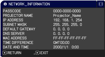 For the details of PASSCODE, see the section 1.5 Selecting the network connection method in the Network Guide.Only the first 16 characters of the projector name are displayed.When the voltage level of the battery for the built in clock decreases, the set time may become incorrect even though accurate date and time are input. Replace the battery suitably (93).IP ADDRESS, SUBNET MASK and DEFAULT GATEWAY indicate “0.0.0.0” when DHCP is ON and the projector has not gotten address from DHCP server. For the details of PASSCODE, see the section 1.5 Selecting the network connection method in the Network Guide.Only the first 16 characters of the projector name are displayed.When the voltage level of the battery for the built in clock decreases, the set time may become incorrect even though accurate date and time are input. Replace the battery suitably (93).IP ADDRESS, SUBNET MASK and DEFAULT GATEWAY indicate “0.0.0.0” when DHCP is ON and the projector has not gotten address from DHCP server. |
| SERVICE | Executing this item restarts and initializes the network functions.Choose the RESTART EXECUTE using the button ▶.Then use the b 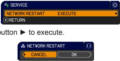 Network will be once cut off when choose restart.If DHCP is selected on, IP address may be changed.After selecting RESTART EXECUTE, NETWORK menu may not be controlled approx. 30 seconds. Network will be once cut off when choose restart.If DHCP is selected on, IP address may be changed.After selecting RESTART EXECUTE, NETWORK menu may not be controlled approx. 30 seconds. |
SECURITY menu
This projector is equipped with security functions. From the SECURITY menu, items shown in the table below can be performed.
To use SECURITY menu: User registration is required before using the security functions.
Enter to the SECURITY menu
- Press the ▶ button. The ENTER PASSWORD box will be displayed.
- Use the ▲/▼/◄/► buttons to enter the registered password. The factory default password is as follows.
Pro9500: 4501
This password can be changed. Move the cursor to the right side of the ENTER PASSWORD box and press the ▶ button to display the SECURITY menu.
- It is strongly recommended the factory default password to be changed as soon as possible.
-
If an incorrect password is input, the ENTER PASSWORD box will be displayed again. If incorrect password is input 3 times, the projector will turn off. Afterwards the projector will turn off every time an incorrect password is input.
-
Items shown in the table below can be performed.
If you have forgotten your password
(1) While the ENTER PASSWORD box is displayed, press and hold the RESET button on the remote control for about 3 seconds or press and hold the INPUT button for 3 seconds while pressing the ▶ button on the projector.
(2) The 10 digit Inquiring Code will be displayed. Contact your dealer with the 10 digit Inquiring Code. Your password will be sent after your user registration information is confirmed.
- If there is no key input for about 55 seconds while the Inquiring Code is displayed, the menu will close. If necessary, repeat the process from (1).
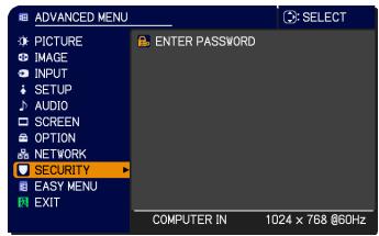
text_image
ADVANCED MENU PICTURE IMAGE INPUT SETUP AUDIO SCREEN OPTION NETWORK SECURITY EASY MENU EXIT ENTER PASSWORD COMPUTER IN 1024 x 768 @60Hz SELECT
text_image
SECURITY ENTER PASSWORD CANCEL 0 0 0 0 OK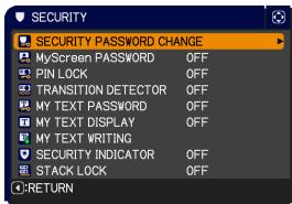
text_image
SECURITY SECURITY PASSWORD CHANGE MyScreen PASSWORD OFF PIN LOCK OFF TRANSITION DETECTOR OFF MY TEXT PASSWORD OFF MY TEXT DISPLAY OFF MY TEXT WRITING SECURITY INDICATOR OFF STACK LOCK OFF RETURN

text_image
SECURITY Inquiring Code 01 2345 6789 OK| Item | Description |
| SECURITY PASSWORD CHANGE | (1) Use the ▲/▼ buttons on the SECURITY menu to select SECURITY PASSWORD CHANGE and press the ▶ button to display the ENTER NEW PASSWORD box.(2) Use the ▲/▼/◄/► buttons to enter the new password.(3) Move the cursor to the right side of the ENTER NEW PASSWORD box and press the ► button to display the NEW PASSWORD AGAIN box, enter the same password again.(4) Move the cursor to the right side of the NEW PASSWORD AGAIN box and press the ► button and the NOTE NEW PASSWORD box will be displayed for about 30 seconds, please make note of the password during this time. Pressing the ENTER button on the remote control or ► button on the projector will close the NOTE NEW PASSWORD box.· Please do not forget your password. |
| MyScreen PASSWORD | The MyScreen PASSWORD function can be used to prohibit access to the MyScreen function and prevent the currently registered MyScreen image from being overwritten.1 Turning on the MyScreen PASSWORD1-1 Use the ▲/▼ buttons on the SECURITY menu to select MyScreen PASSWORD and press the ▶ button to display the MyScreen PASSWORD on/off menu.1-2 Use the ▲/▼ buttons on the MyScreen PASSWORD on/off menu to select ON.The ENTER NEW PASSWORD box (small) will be displayed.1-3 Use the ▲/▼/◄/► buttons to enter the password. Move the cursor to the right side of the ENTER NEW PASSWORD box (small) and press the ► button to display the NEW PASSWORD AGAIN box, enter the same PASSWORD again.1-4 Move the cursor to the right side of the NEW PASSWORD AGAIN box and press the ► button to display the NOTE NEW PASSWORD box for about 30 seconds, please make note of the password during this time.Pressing the ENTER button on the remote control or ► button on the projector will return to MyScreen PASSWORD on/off menu.When a password is set for MyScreen:· The MyScreen registration function (and menu) will be unavailable.· The MyScreen Lock menu will be unavailable.· The START UP setting will be locked on MyScreen (and the menu will be unavailable).Turning the MyScreen PASSWORD off will allow normal operation of these functions.· Please do not forget your MyScreen PASSWORD.2 Turning off the MyScreen PASSWORD2-1 Follow the procedure in 1-1 to display the MyScreen PASSWORD on/off menu.2-2 Select OFF to display the ENTER PASSWORD box (large). Enter the registered password and the screen will return to the MyScreen PASSWORD on/off menu.If an incorrect PASSWORD is input, the menu will close. If necessary, repeat the process from 2-1.3 If you have forgotten your password3-1 Follow the procedure in 1-1 to display the MyScreen PASSWORD on/off menu.3-2 Select OFF to display the ENTER PASSWORD box (large). The 10 digit Inquiring Code will be displayed inside the box.3-3 Contact your dealer with the 10 digit Inquiring Code. Your password will be sent after your user registration information is confirmed. |
(continued on next page)
| Item | Description |
| PIN LOCK | PIN LOCK is a function which prevents the projector from being used unless a registered Code is input.1 Turning on the PIN LOCK1-1 Use the ▲/▼ buttons on the SECURITY menu to select PIN LOCK and press the ▶ button or the ENTER button to display the PIN LOCK on/off  menu.1-2 Use the ▲/▼ buttons on the PIN LOCK on/off menu to select ON and the Enter PIN Code box will be displayed.1-3 Input a 4 part PIN code using the ▲/▼/◄/►, COMPUTER or INPUT button.The PIN Code again box will appear. Reenter the same PIN code. This will complete the PIN code registration.• If there is no key input for about 55 seconds while the Enter PIN Code box or the PIN Code again box is displayed, the menu will close. If necessary, repeat the process from 1-1.Afterwards, anytime the projector is restarted after AC power is turned off the Enter PIN Code box will be displayed. Enter the registered PIN code. The projector can be used after entering the registered PIN code. If an incorrect PIN code is input, the Enter PIN code box will be displayed again. If an incorrect PIN code is input 3 times, the projector will turn off. Afterwards the projector will turn off every time an incorrect PIN code is input. The projector will also turn off if there is no key input for about 5 minutes while the Enter PIN code box is displayed.This function will activate only when the projector is started after AC power is turned off.• Please do not forget your PIN code.2 Turning off the PIN LOCK2-1 Follow the procedure in 1-1 to display the PIN LOCK on/off menu.2-2 Use the ▲/▼ buttons to select OFF and the Enter PIN Code box will be displayed.Enter the registered PIN code to turn the PIN LOCK function off.If an incorrect PIN code is input 3 times, the projector will turn off.3 If you have forgotten your PIN code3-1 While the Enter PIN code box is displayed, press and hold the RESET button for three seconds or press and hold the INPUT button for 3 seconds while pressing the ▶ button on the projector.The 10 digit Inquiring Code will be displayed.• If there is no key input for about 5 minutes while the Inquiring Code is displayed, the projector will turn off.3-2 Contact your dealer with the 10 digit Inquiring Code. Your PIN code will be sent after your user registration information is confirmed. menu.1-2 Use the ▲/▼ buttons on the PIN LOCK on/off menu to select ON and the Enter PIN Code box will be displayed.1-3 Input a 4 part PIN code using the ▲/▼/◄/►, COMPUTER or INPUT button.The PIN Code again box will appear. Reenter the same PIN code. This will complete the PIN code registration.• If there is no key input for about 55 seconds while the Enter PIN Code box or the PIN Code again box is displayed, the menu will close. If necessary, repeat the process from 1-1.Afterwards, anytime the projector is restarted after AC power is turned off the Enter PIN Code box will be displayed. Enter the registered PIN code. The projector can be used after entering the registered PIN code. If an incorrect PIN code is input, the Enter PIN code box will be displayed again. If an incorrect PIN code is input 3 times, the projector will turn off. Afterwards the projector will turn off every time an incorrect PIN code is input. The projector will also turn off if there is no key input for about 5 minutes while the Enter PIN code box is displayed.This function will activate only when the projector is started after AC power is turned off.• Please do not forget your PIN code.2 Turning off the PIN LOCK2-1 Follow the procedure in 1-1 to display the PIN LOCK on/off menu.2-2 Use the ▲/▼ buttons to select OFF and the Enter PIN Code box will be displayed.Enter the registered PIN code to turn the PIN LOCK function off.If an incorrect PIN code is input 3 times, the projector will turn off.3 If you have forgotten your PIN code3-1 While the Enter PIN code box is displayed, press and hold the RESET button for three seconds or press and hold the INPUT button for 3 seconds while pressing the ▶ button on the projector.The 10 digit Inquiring Code will be displayed.• If there is no key input for about 5 minutes while the Inquiring Code is displayed, the projector will turn off.3-2 Contact your dealer with the 10 digit Inquiring Code. Your PIN code will be sent after your user registration information is confirmed. |
(continued on next page)
| Item | Description | |
| TRANSITION DETECTOR | If this function is set to ON when the vertical angle of the projector or MIRROR setting at which the projector is turned on is different than the previously recorded, the TRANSITION DETECTOR ON alarm will be displayed and the projector will not display the input signal. • To display the signal again, set this function OFF. • After about 5 minutes of displaying the TRANSITION DETECTOR ON alarm, the lamp will turn off. • Keystone adjustment feature has been prohibited as long as the Transition Detector function is on.1 Turning on the TRANSITION DETECTOR1-1 Use the ▲/▼ buttons on the SECURITY menu to select TRANSITION DETECTOR and press the ▶ or the ENTER button to display the TRANSITION DETECTOR on/off menu.1-2 Use the ▲/▼ buttons on the TRANSITION DETECTOR on/off menu to select ON. Select ON and the current angle and MIRROR setting will be recorded. The ENTER NEW PASSWORD box (small) will be displayed.1-3 Use the ▲/▼/◄/► buttons to enter a password. Move the cursor to the right side of the ENTER NEW PASSWORD box (small) and press the ▶ button to display the NEW PASSWORD AGAIN box, enter the same password again.1-4 Move the cursor to the right side of the NEW PASSWORD AGAIN box and press the ▶ button to display the NOTE NEW PASSWORD box for about 30 seconds, please make note of the password during this time. Pressing the ENTER button on the remote control or the ▶ button on the projector will return to the TRANSITION DETECTOR on/off menu. • Please do not forget your TRANSITION DETECTOR password. • This function will activate only when the projector is started after turning off the AC power. • This feature may not function properly if the projector is not in a stable position when ON is selected.2 Turning off the TRANSITION DETECTOR2-1 Follow the procedure in 1-1 to display the TRANSITION DETECTOR on/off menu.2-2 Select OFF to display the ENTER PASSWORD box (large). Enter the registered password and the screen will return to the TRANSITION DETECTOR on/off menu. If an incorrect password is input, the menu will close. If necessary, repeat the process from 2-1.3 If you have forgotten your password3-1 Follow the procedure in 1-1 to display the TRANSITION DETECTOR on/off menu.3-2 Select OFF to display the ENTER PASSWORD box (large). The 10 digit Inquiring Code will be displayed inside the box.3-3 Contact your dealer with the 10 digit Inquiring Code. Your password will be sent after your user registration information is confirmed. | 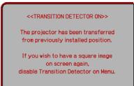 ______ ______ |
| Item | Description |
| MY TEXT PASSWORD | The MY TEXT PASSWORD function can prevent the MY TEXT from being overwritten. When the password is set for the MY TEXT;• The MY TEXT DISPLAY menu will be unavailable, which can prohibit changing the DISPLAY setting.• The MY TEXT WRITING menu will be unavailable, which can prevent the MY TEXT from being overwritten.1 Turning on the MY TEXT PASSWORD1-1 Use the ▲/▼ buttons on the SECURITY menu to select the MY TEXT PASSWORD and press the ► button to display the MY TEXT PASSWORD on/off menu.  1-2 Use the ▲/▼ buttons on the MY TEXT PASSWORD on/off menu to select ON. The ENTER NEW PASSWORD box (small) will be displayed. 1-2 Use the ▲/▼ buttons on the MY TEXT PASSWORD on/off menu to select ON. The ENTER NEW PASSWORD box (small) will be displayed.  1-3 Use the ▲/▼/◄/► buttons to enter the password. Move the cursor to the right side of the ENTER NEW PASSWORD box (small) and press the ► button to display the NEW PASSWORD AGAIN box, and then enter the same password again. ENTER NEW PASSWORD box (small)1-4 Move the cursor to the right side of the NEW PASSWORD AGAIN box and press ► button to display the NOTE NEW PASSWORD box for about 30 seconds, then please make note of the password during this time. 1-3 Use the ▲/▼/◄/► buttons to enter the password. Move the cursor to the right side of the ENTER NEW PASSWORD box (small) and press the ► button to display the NEW PASSWORD AGAIN box, and then enter the same password again. ENTER NEW PASSWORD box (small)1-4 Move the cursor to the right side of the NEW PASSWORD AGAIN box and press ► button to display the NOTE NEW PASSWORD box for about 30 seconds, then please make note of the password during this time.   Pressing the ENTER button on the remote control or ► button on the projector will return to the MY TEXT PASSWORD on/off menu.2 Turning off the MY TEXT PASSWORD2-1 Follow the procedure in 1-1 to display the MY TEXT PASSWORD on/off menu.2-2 Select OFF to display the ENTER PASSWORD box (large). Enter the registered password and the screen will return to the MY TEXT PASSWORD on/off menu. Pressing the ENTER button on the remote control or ► button on the projector will return to the MY TEXT PASSWORD on/off menu.2 Turning off the MY TEXT PASSWORD2-1 Follow the procedure in 1-1 to display the MY TEXT PASSWORD on/off menu.2-2 Select OFF to display the ENTER PASSWORD box (large). Enter the registered password and the screen will return to the MY TEXT PASSWORD on/off menu. 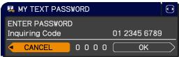 ENTER PASSWORD box (large)If an incorrect password is input, the menu will close. If necessary, repeat the process from 2-13 If you have forgotten your password3-1 Follow the procedure in 1-1 to display the MY TEXT PASSWORD on/off menu.3-2 Select OFF to display the ENTER PASSWORD box (large). The 10 digit inquiring code will be displayed inside the box.3-3 Contact your dealer with the 10 digit inquiring code. Your password will be sent after your user registration information is confirmed. ENTER PASSWORD box (large)If an incorrect password is input, the menu will close. If necessary, repeat the process from 2-13 If you have forgotten your password3-1 Follow the procedure in 1-1 to display the MY TEXT PASSWORD on/off menu.3-2 Select OFF to display the ENTER PASSWORD box (large). The 10 digit inquiring code will be displayed inside the box.3-3 Contact your dealer with the 10 digit inquiring code. Your password will be sent after your user registration information is confirmed. |
(continued on next page)
| Item | Description | |
| MY TEXT DISPLAY | (1) Use the ▲/▼ buttons on the SECURITY menu to select the MY TEXT DISPLAY and press the ▶ or ENTER button to display the MY TEXT DISPLAY on/off menu. |  |
| (2) Use the ▲/▼ buttons on the MY TEXT DISPLAY on/off menu to select on or off.ON ⇔ OFFWhen it is set ON, the MY TEXT will be displayed on the START UP screen and the INPUT INFORMATION when the INFORMATION on the SERVICE menu is chosen.· This function is available only when the MY TEXT PASSWORD function is set to the OFF. | 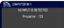 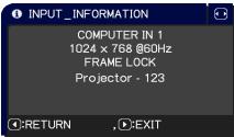 | |
| MY TEXT WRITING | (1) Use the ▲/▼ buttons on the SECURITY menu to select the MY TEXT WRITING and press the ▶ button. The MY TEXT WRITING dialog will be displayed.(2) The current MY TEXT will be displayed on the first 3 lines. If not yet written, the lines will be blank.Use the ▲/▼/◄/► buttons and the ENTER or INPUT button to select and enter characters. To erase 1 character at one time, press the RESET button or press the ◀ and INPUT button at the same time. Also if you move the cursor to DELETE or ALL CLEAR on screen and press the ENTER or INPUT button, 1 character or all characters will be erased. The MY TEXT can be input up to 24 characters on each line.(3) To change an already inserted character, press the ▲/▼ button to move the cursor to one of the first 3 lines, and use the ◀/► buttons to move the cursor on the character to be changed.After pressing the ENTER or INPUT button, the character is selected. Then, follow the same procedure as described at the item (2) above.(4) To finish entering text, move the cursor to the OK on screen and press the ►, ENTER or INPUT button. To revert to the previous MY TEXT without saving changes, move the cursor to the CANCEL on screen and press the ◀, ENTER or INPUT button.· The MY TEXT WRITING function is available only when the MY TEXT PASSWORD function is set to OFF. | 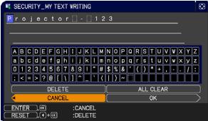 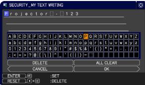 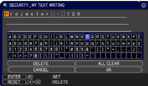 |
| SECURITY INDICATOR | Selecting this item displays the SECURITY INDICATOR dialog. Use the ▲/▼ buttons to select ON or OFF.ON ⇔ OFFWhen ON is selected while PIN LOCK or TRANSITION DETECTOR is ON, the SECURITY indicator blinks in the standby state (73, 74). | |
| STACK LOCK | Selecting this item displays the STACK LOCK dialog. For more information, please see Instant Stack Guide. | |
Presentation tools
The projector has the following two convenient tools that enable on-screen presentations easily and quickly:
- PC-LESS Presentation
- USB Display
PC-LESS Presentation
The PC-LESS Presentation reads image data from storage media inserted into the USB TYPE A port and displays the image on the following modes.
The PC-LESS Presentation can be started by selecting the USB TYPE A port as the input source. This feature allows you to make your presentations without using your computer.
- Thumbnail mode
- Full Screen mode
- Slideshow mode
[Supported storage media]
- USB memory (USB memory type, USB hard disk and USB card reader type)
NOTE • USB readers (adapters) that have more than one USB slot may not work (if the adapter is acknowledged as multiple devices connected).
- USB hubs may not work.
- USB devices with security software may not work.
- Be careful when inserting or removing a USB device.
[Supported format]
• FAT12, FAT16 and FAT32
NOTE • NTFS is not supported.
[Supported file format]
- JPEG (.jpeg, .jpg) * Progressive is not supported.
- Bitmap (.bmp) * 16bit mode and compressed bitmap is not supported.
- PNG (.png) * Interlace PNG is not supported.
- GIF (.gif)
NOTE • Files with a resolution larger than the following are not supported.
Pro9500: 1024X768
- Files with a resolution smaller than 36x36 are not supported.
- Files with a resolution smaller than 100x100 may not be displayed.
- Some supported files may not be displayed.
- Only a frame appears when the content of image data cannot be displayed in the Thumbnail mode.
PC-LESS Presentation (continued)
Thumbnail mode
The Thumbnail mode displays the images stored in a USB storage device on the Thumbnail screen. Maximum 20 images are displayed in a screen. If you wish, you can jump into the Full Screen mode or Slideshow mode, after you select some images in the Thumbnail mode. The Thumbnail mode will be started as the primary function of the PC-LESS Presentation after selecting the USB TYPE A port as the input source.

text_image
USB TYPE A 001/003pape SORT SLIDESHOW Folder_1 Folder_2 000.jpg 001.jpg 002.jpg 003.jpg 004.jpg 005.jpg 006.jpg 007.jpg 008.jpg 009.jpg 010.jpg 011.jpg 012.jpg 013.jpg 014.jpg 015.jpg 016.jpg 017.jpg INPUT MENU REMOVE USB ENTER SET Selected image Thumbnail menuPC-LESS Presentation (continued)
Operating by buttons or keys
You can control the images in the Thumbnail screen with the remote control or keypad or a web browser software. The following functions can be supported while the Thumbnail is displayed.
| Button operation | Functions | ||
| The remote control | The keypad on the projector | Web Remote in web browser software. | |
| ▲/▼/◄/► | ▲/▼/◄/► | ▲/▼/◄/► | Move cursor |
| PAGE UP PAGE DOWN | - | PAGE UP PAGE DOWN | Switches pages |
| ENTER | INPUT | ENTER | • Displays the selected image on the Full Screen mode when a cursor is on a thumbnail image.• Displays the SETUP menu for the selected image when a cursor is on a thumbnail image number. |
The SETUP menu for the selected image
| Item | Functions | |
| SETUP | Use the ◀/▶ cursor buttons to switch each setting or use the ▶ cursor button to execute the functions as follows. | |
| RETURN | Press the ▶ cursor button or ENTER to return to the Thumbnail screen. | |
| START | Switch to ON to set the selected image as the first image in the Slideshow. This setting information will be saved in the “playlist.txt” file. | |
| STOP | Switch to ON to set the selected image as the last image in the Slideshow. This setting information will be saved in the “playlist.txt” file. | |
| SKIP | Switch to ON to skip the selected image in the Slideshow. This setting information will be saved in the “playlist.txt” file. | |
| ROTATE | Press the ▶ cursor button or ENTER to rotate the selected image 90 degrees clockwise. This setting information will be saved in the “playlist.txt” file. | |
PC-LESS Presentation (continued)
Operating by the menu on the Thumbnail screen
You can also control the images by using the menu on the Thumbnail screen.
| Item | Functions | |
| Moves to an upper folder. | ||
| SORT | Allows you to sort files and folders as following. | |
| RETURN | Press the ▶ cursor button or ENTER to return to the Thumbnail screen. | |
| NAME UP | Sorts in ascending order by file name. | |
| NAME DOWN | Sorts in descending order by file name. | |
| DATE UP | Sorts in ascending order by file date. | |
| DATE DOWN | Sorts in descending order.by file date. | |
| ▲/▼ | Go to previous / next page. | |
| SLIDESHOW | Configures and starts the Slideshow. | |
| RETURN | Press the ▶ cursor button or ENTER to return to the Thumbnail screen. | |
| PLAY | Press the ▶ cursor button or ENTER to start the Slideshow. | |
| START | Sets the beginning number of the Slideshow. | |
| STOP | Sets the end number of the Slideshow. | |
| INTERVAL | Sets the interval time of the Slideshow. | |
| PLAY MODE | Selects the Slideshow mode. | |
| INPUT | Switches the input port. | |
| MENU | Displays the menu. | |
| REMOVE USB | Be sure to use this function before removing USB storage device from the projector. After that, the projector will not recognize a USB storage device until you insert it again into the USB TYPE A input port. | |
PC-LESS Presentation (continued)
NOTE • These operations are not accessible while the projector OSD is displayed.
- The Thumbnail mode shows 20 pictures in 1 page as maximum.
- It is not possible to change the input port by using the INPUT button when the Thumbnail screen, Slideshow, or Full Screen is displayed.
- Some error icons will be displayed in the Thumbnail.

This file seems to be broken or not supported format.


A file that cannot be displayed on the thumbnail screen is indicated by a file format icon.


PC-LESS Presentation (continued)
Full Screen Mode
The Full Screen mode shows a full display image. To display in Full Screen mode, select an image in the Thumbnail screen. Then press the ENTER button on the remote control or the INPUT button on the keypad, or click [ENTER] on the Web Remote Control.

text_image
Full screen displayThe following functions can be supported in the Full Screen mode.
| Button operation | Functions | ||
| The remote control | The keypad on the projector | Web Remote in web browser software. | |
| ▼►orPAGE DOWN | ▼or► | ▼►orPAGE DOWN | Shows the next picture. |
| ▲◄orPAGE UP | ▲or◄ | ▲◄orPAGE UP | Shows the previous picture. |
| ENTER | INPUT | ENTER | Displays Thumbnail. |
NOTE • These operations are not accessible while the projector OSD is displayed. • It is not possible to change the input port by using the INPUT button when the Thumbnail screen, Slideshow, or Full Screen is displayed.
PC-LESS Presentation (continued)
Slideshow mode
The Slideshow mode displays images in full screen and switches the images at intervals set in INTERVAL on the Thumbnail screen menu.
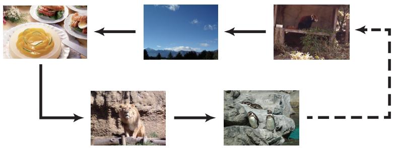
flowchart
graph TD
    A["Food with plate and dish"] <--> B["Landscape with blue sky and mountains"]
    B <--> C["Park with animal"]
    C <--> D["Animal with penguin"]
    D --> E["Rock with penguin"]
    E -.-> F["Environment with penguins"]
    F -.-> A
You can start this function from the Slideshow menu. To display the Slideshow menu, select the SLIDESHOW button in the Thumbnail mode and press the ENTER button on the remote control or INPUT button on the projector.
The following operations can be accessible while the Slideshow is displayed.
| Button operation | Functions | ||
| The remote control | The keypad on the projector | Web Remote in web browser software. | |
| ENTER | INPUT | ENTER | Displays thumbnail |
* These operations are not accessible while the projector OSD is displayed.
NOTE • It is not possible to change the input port by using the INPUT button when the Thumbnail screen, Slideshow, or Full Screen is displayed. • When the Slideshow mode is set to ONE TIME, the last slide of the presentation will be held on screen till the ENTER button on the remote control or Web Remote Control, or INPUT button on the projector is pushed.
PC-LESS Presentation (continued)
You can play the Slideshow at your desired configuration. Configure the Slideshow items in the Thumbnail.
1) RETURN : Returns to the thumbnail mode.
2) PLAY : Play the Slideshow.
3) START : Set the beginning number of the Slideshow.
4) STOP : Set the end number of the Slideshow.
5) INTERVAL : Set the interval time of the Slideshow. It is not recommend to set the interval time very short something like several seconds, because it may take more than several seconds to read and display an image file if it is stored in very deep layer directory or if so many files are stored in the same directory.
6) PLAY MODE : Select the Slideshow mode.
ONE TIME : Play the Slideshow one time.
ENDLESS : Play the Slideshow endless.
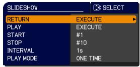
text_image
SLIDESHOW SELECT RETURN EXECUTE PLAY EXECUTE START #1 STOP #10 INTERVAL 1s PLAY MODE ONE TIMENOTE • The settings of the Slideshow are saved to the “playlist.txt” file that is stored in the storage media. If the file is not existed, it is generated automatically.
- The settings for the START, STOP, INTERVAL, and PLAY MODE are saved to the Playlist.
- If the storage media is under the write protection or the “playlist.txt” is the read only type file, it is impossible to change the settings of the Slideshow.
PC-LESS Presentation (continued)
Playlist
The Playlist is a DOS format text file, which decides the order of displayed still image files in the Thumbnail or Slideshow.
The playlist file name is “playlist.txt” and it can be edited on a computer.
It is created in the folder that contains the selected image files when the PC-LESS Presentation is started or the Slideshow is configured.
[Example of "playlist.txt" files]
START setting : STOP setting : INTERVAL setting : PLAY MODE setting :
img001.jpg: : : :
img002.jpg:600:::
img003.jpg:700:rot1::
img004.jpg: : :SKIP:
img005.jpg:1000:rot2:SKIP:
The "playlist.txt" file contains the following information.
Each piece of information requires to be separated by “:”, and “:” at the end of each line.
1st line: START, STOP, INTERVAL and PLAY MODE settings.
2nd line and after: file name, interval time, rotation setting and skip setting.
interval time: It can be set from 0 to 999900 (ms) with an increment of 100 (ms).
rotation setting: “rot1” means a rotation at 90 degrees clockwise; “rot2” and “rot3” increase another 90 degrees in order.
skip setting: "SKIP" means that the image will not be displayed in the Slideshow.
NOTE • The maximum length in a line on the "playlist.txt" file is 255 characters including linefeed. If any line exceeds the limit, the "playlist.txt" file becomes invalid.
- Up to 999 files can be registered to the Playlist. However, if some folders exist in the same directory the limit number is decreased by the number of folders.
Any files over the limit will not be shown in the Slideshow.
- If the storage device is protected or does not have sufficient space, the “playlist.txt” file cannot be created.
- For the Slideshow settings, refer to the section Slideshow mode.
USB Display
The projector can display images transferred from a computer via an USB cable. Hardware and software requirement for computer
- OS: One of the following. (32 bit version only)
Windows ^® XP Home Edition /Professional Edition
Windows Vista ^® Home Basic /Home Premium /Business /Ultimate /Enterprise
Windows ^® 7 Starter /Home Basic /Home Premium /Professional / Ultimate /Enterprise
• CPU: Pentium 4 (2.8 GHz or higher)
• Graphic card: 16 bit, XGA or higher
• Memory: 512 MB or higher
- Hard disk space: 30 MB or higher
- USB Port
- USB cable : 1 piece
Select the USB DISPLAY for the USB TYPE B item in the OPTION menu. When you connect your computer to the USB TYPE B port on the projector using a USB cable, the projector will be recognized as a CD-ROM drive on your computer. Then, the software in the projector, "LiveViewerLiteForUSB.exe", will run automatically and the application, "LiveViewer Lite for USB", will be ready on your computer for the USB Display. The application, "LiveViewer Lite for USB", will be automatically closed when the USB cable is unplugged.
NOTE • If the software does not start automatically (this is typically because CD-ROM autorun is disabled on your OS), follow the instructions below.
(1) Click on the [Start] button on the toolbar and select the "Run"
(2) Enter F:\LiveViewerLiteForUSB.exe and then press the [OK]
If your CD-ROM drive is not drive F on your computer, you will need to replace F with the correct drive letter assigned to your CD-ROM drive.
- CD-ROM autorun is disabled while the screen saver is running.
- The image transmission from the computer is suspended while the password-protected screen saver is running. To resume the transmission, exit the screen saver.
- Check our web site for the latest version of the software and its manual.
Follow the instructions that can be obtained at the site for updating.
This application will appear in the Windows notification area once it starts. You can quit the application from your computer by selecting “Quit” on the menu.

text_image
3:00 PMNOTE • The “LiveViewer” (refer to the Network Guide) and this application cannot be used at the same time. If you connect your computer to the projector by using a USB cable
while the "LiveViewer" is running, the following message will be displayed.
- If any application software having the firewall function is installed into your computer, make the firwall function invalid with following the user's manual.
- Some security software may block image transmission. Please change the security software setting to allow the use of "LiveViewer Lite for USB".
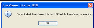
text_image
LiveViewer Lite for USB Cannot start LiveViewer Lite for USB while LiveViewer is running. OKUSB Display (continued)
Right-Click menu
The menu shown in the right will be displayed when you right-click the application icon in the Windows notification area.

text_image
Display Quit 3:00 PMDisplay : The Floating menu is displayed, and the icon disappears from the Windows notification area.
Quit : The application is closed, and the icon disappears from the Windows notification area.
NOTE • If you wish to restart the application, you need to unplug the USB cable and plug it again.
Floating menu
If you select "Display" on the Right-Click menu, the Floating menu shown in the right will appear on your computer screen.
① Start capture button
The transmission to the projector is started and the images will be displayed.
② Stop button
The image transmission is stopped.
③ Hold button
The image on the projector's screen is temporally frozen. The last image before the button is clicked is remained on the screen. You can revise the image data on your computer without showing it on the projector's screen.
④ Option button
The Options window is displayed.
⑤ Minimize button
The Floating menu is closed, and the icon reappears in the Windows notification area.
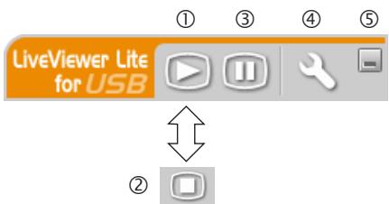
text_image
LiveViewer Lite for USB ① ③ ④ ⑤ ②NOTE • If you click the Start capture button and/or Stop button repeatedly, images may not be displayed on the screen.
USB Display (continued)
Options window
If you select the Option button on the Floating menu, the Options window is displayed.
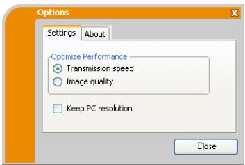
text_image
Options Settings About Optimize Performance Transmission speed Image quality Keep PC resolution CloseOptimize Performance
The “LiveViewer Lite for USB” captures screenshots in JPEG data and sends them to the projector. The “LiveViewer Lite for USB” has two options that have different compression rate of JPEG data.
Transmission speed
Speed takes priority over Image quality.
It makes JPEG compression rate higher.
The screen on the projector is rewritten quicker because the
transferred data is smaller, but the image quality is worse.
Image quality
Image quality takes priority over Speed.
It makes JPEG compression rate lower.
The screen on the projector is rewritten slower because the transferred data is larger, but the image quality is better.
Keep PC resolution
If you remove the check mark from the [Keep PC resolution] box, the screen resolution of your computer will be switched as follows, and the display speed may be faster.
Pro9500: 1024X768 (XGA)
If your computer does not support the display resolution specified above, a smaller resolution that is the largest among the resolutions that are supported by the computer will be selected.
NOTE • When the resolution is changed, the arrangement of icons on computer desktop screen may be changed.
About
The version information of the "LiveViewer Lite for USB".
Maintenance
Replacing the lamp
A lamp has finite product life. Using the lamp for long periods of time could cause the pictures darker or the color tone poor. Note that each lamp has a different lifetime, and some may burst or burn out soon after you start using them.
Preparation of a new lamp and early replacement are recommended. To prepare a new lamp, make contact with your dealer and tell the lamp type number.
Type number : RLC-063 (DT01175)
Replacing the lamp
- Turn the projector off, and unplug the power cord. Allow the projector to cool for at least 45 minutes.
- Prepare a new lamp. If the projector is mounted on a ceiling, or if the lamp has broken, also ask the dealer to replace the lamp.
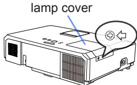
text_image
lamp coverIn case of replacement by yourself, follow the following procedure.
-
Loosen the screw (marked by arrow) of the lamp cover and then slide and lift the lamp cover to the side to remove it.
-
Loosen the 3 screws (marked by arrow) of the lamp, and slowly pick up the lamp by the handles. Never loosen any other screws.
-
Insert the new lamp, and retighten firmly the 3 screws of the lamp that are loosened in the previous process to lock it in place.
-
While putting the interlocking parts of the lamp cover and the projector together, slide the lamp cover back in place. Then firmly fasten the screw of the lamp cover.
-
Turn the projector on and reset the lamp time using the LAMP TIME item in the OPTION menu.
(1) Press the MENU button to display a menu.
(2) Point at the ADVANCED MENU in the menu using the ▼/▲ button, then press the ▶ button.
(3) Point at the OPTION in the left column of the menu using the ▼/▲button, then press the ▶ button.
(4) Point at the LAMP TIME using the ▼/▲ button, then press the ▶ button. A dialog will appear.
(5) Press the ▶ button to select "OK" on the dialog. It performs resetting the lamp time.
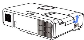
natural_image
Line drawing of a projector with ventilation slots and a blue arrow indicating direction (no text or symbols)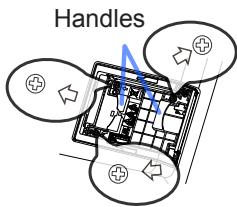
text_image
Handles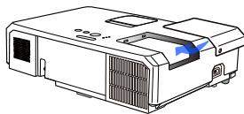
natural_image
Line drawing of a projector with ventilation slots and a blue arrow indicating direction (no text or symbols)⚠️ CAUTION ▶ Do not touch any inner space of the projector, while the lamp is taken out.
NOTE • Please reset the lamp time only when you have replaced the lamp, for a suitable indication about the lamp.
Replacing the lamp (continued)
Lamp warning

HIGH VOLTAGE

HIGH TEMPERATURE

HIGH PRESSURE
⚠ WARNING ▶ The projector uses a high-pressure mercury glass lamp. The lamp can break with a loud bang, or burn out, if jolted or scratched, handled while hot, or worn over time. Note that each lamp has a different lifetime, and some may burst or burn out soon after you start using them. In addition, if the bulb bursts, it is possible for shards of glass to fly into the lamp housing, and for gas containing mercury and dust containing fine particles of glass to escape from the projector's vent holes.
▶ About disposal of a lamp: This product contains a mercury lamp; do not put it in a trash. Dispose of it in accordance with environmental laws.
- For lamp recycling, go to www.lamprecycle.org (in the US).
- For product disposal, consult your local government agency or www.eiae.org (in the US) or www.epsc.ca (in Canada).
For more information, call your dealer.
 Disconnect the plug from the power outlet Disconnect the plug from the power outlet | ·If the lamp should break (it will make a loud bang when it does), unplug the power cord from the outlet, and make sure to request a replacement lamp from your local dealer. Note that shards of glass could damage the projector's internals, or cause injury during handling, so please do not try to clean the projector or replace the lamp yourself.·If the lamp should break (it will make a loud bang when it does), ventilate the room well, and make sure not to inhale the gas or fine particles that come out from the projector's vent holes, and not to get them into your eyes or mouth.·Before replacing the lamp, turn the projector off and unplug the power cord, then wait at least 45 minutes for the lamp to cool sufficiently. Handling the lamp while hot can cause burns, as well as damaging the lamp. |
 | ·Never unscrew except the appointed (marked by an arrow) screws.·Do not open the lamp cover while the projector is suspended from a ceiling. This is dangerous, since if the lamp's bulb has broken, the shards will fall out when the cover is opened. In addition, working in high places is dangerous, so ask your local dealer to have the lamp replaced even if the bulb is not broken.·Do not use the projector with the lamp cover removed. At the lamp replacing, make sure that the screws are screwed in firmly. Loose screws could result in damage or injury. |
 | ·Use only the lamp of the specified type. Use of a lamp that does not meet the lamp specifications for this model could cause a fire, damage or shorten the life of this product.·If the lamp breaks soon after the first time it is used, it is possible that there are electrical problems elsewhere besides the lamp. If this happens, consult your local dealer or a service representative.·Handle with care: jolting or scratching could cause the lamp bulb to burst during use.·Using the lamp for long periods of time, could cause it dark, not to light up or to burst. When the pictures appear dark, or when the color tone is poor, please replace the lamp as soon as possible. Do not use old (used) lamps; this is a cause of breakage. |
Cleaning and replacing the air filter
Please check and clean the air filter periodically. When the indicators or a message prompts you to clean the air filter, comply with it as soon as possible. The air filter of this projector consists of a filter cover and a filter unit with two types of filter. If one or both of the filters are damaged or heavily soiled, replace the filter unit with a new one.
The specified filter unit also comes with a replacement lamp for this projector. Please replace the filter unit as well when you replace the lamp.
- Turn the projector off, and unplug the power cord. Allow the projector to sufficiently cool down.
- Use a vacuum cleaner on and around the filter cover.
- Pick and pull up the filter cover knobs to take it off.
- Press up slightly the bottom side knobs to unlock the bottom side of the filter unit. Pull the center knob to take the filter unit off.
- Use a vacuum cleaner for the filter vent of the projector and the outer side of the filter unit.
- The filter unit consists of two parts. Press down around the interlocking parts to unlock, then separate the two parts.
- Use a vacuum cleaner for the inner side of each part of the filter unit to clean them up. If the filters are damaged or heavily soiled, replace them with the new ones.
- Combine the two parts to reassemble the filter unit.
- Put the filter unit back into the projector.
(continued on next page)
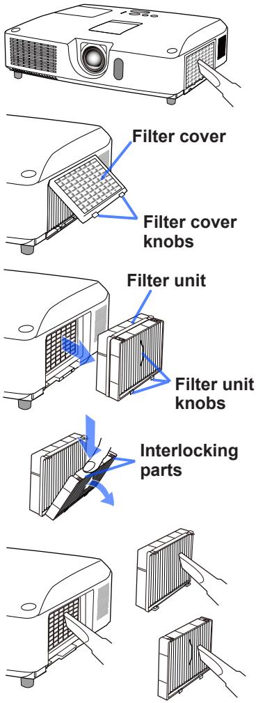
text_image
Filter cover Filter cover knobs Filter unit Filter unit knobs Interlocking partsCleaning and replacing the air filter (continued)
-
Put the filter cover back into the place.
-
Turn the projector on and reset the filter time using the FILTER TIME item in the EASY MENU.
(1) Press the MENU button to display a menu.
(2) Point at the FILTER TIME using the ▲/▼ cursor buttons, then press the ▶ cursor (or the ENTER / the RESET) button. A dialog will appear.
(3) Press the ▶ cursor button to select the "OK" on the dialog. It performs resetting the filter time.
⚠ WARNING ▶ Before taking care of the air filter, make sure the power cable is not plugged in, then allow the projector to cool sufficiently.
▶ Use only the air filter of the specified type. Do not use the projector without the air filter or the filter cover. It could result in a fire or malfunction to the projector.
▶ Clean the air filter periodically. If the air filter becomes clogged by dust or the like, internal temperatures rise and could cause a fire, a burn or malfunction to the projector.
NOTE • Please reset the filter time only when you have cleaned or replaced the air filter, for a suitable indication about the air filter.
- The projector may display the message such as the “CHECK THE AIR FLOW” or turn off the projector, to prevent the internal heat level rising.
Replacing the internal clock battery
This projector has internal clock that uses a battery. When the clock of the network function does not work correctly, please try solution by replacement of the battery: HITACHI MAXELL, part number CR2032 or CR2032H.
- Turn the projector off, and unplug the power cord. Allow the projector to cool sufficiently.
- After making sure that the projector has cooled adequately, slowly turn over the projector, so that the bottom is facing.
- There is a raised dot near the battery cover at the bottom of the projector. Turn the cover in the direction indicated OPEN to position one end of the slit on the cover with the dot, using a coin or the like. And then pick the cover up to remove it.
- Pry up the battery using a flathead screwdriver or the like to take it out. While prying it up, put a finger lightly on the battery since it may pop out of the holder.
- Replace with a new battery of the specified type. With the plus side facing up, slide the battery under the claw of the spring fitting. And press down on the battery until it snaps into place.
- Replace the battery cover in place, then turn it in the direction indicated CLOSE to position the knob of the cover with the dot on the bottom case to fix the cover, using a coin or the like.
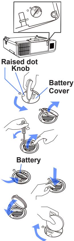
flowchart
graph TD
    A["Raised dot Knob"] --> B["Battery Cover"]
    B --> C["Battery"]
    C --> D["Final Discharge"]
NOTE • The internal clock will be initialized by removing the battery. For setting the clock, see the Network Guide.
⚠ WARNING ▶ Be careful of handling a battery, as a battery can cause explosion, cracking or leakage, which could result in a fire, an injury, and environment pollution.
- Use only the specified and perfect battery. Do not use a battery with damage, such as a scratch, a dent, rust or leakage.
- When replacing the battery, replace it with a new battery.
- When a battery leaked, wipe the leakage out well with a waste cloth. If the leakage adhered to your body, immediately rinse it well with water. When a battery leaked in the battery holder, replace the batteries after wiping the leakage out.
- Make sure the plus and minus terminals are correctly aligned when loading a battery.
- Do not work on a battery; for example recharging or soldering.
- Keep a battery in a dark, cool and dry place. Never expose a battery to a fire or water.
- Keep a battery away from children and pets. Be careful for them not to swallow a battery. If swallowed consult a physician immediately for emergency treatment.
- Obey the local laws on disposing a battery.
Other care
Inside of the projector
In order to ensure the safe use of your projector, please have it cleaned and inspected by your dealer about once every year.
Caring for the lens
If the lens is flawed, soiled or fogged, it could cause deterioration of display quality. Please take care of the lens, being cautious of handling.
- Turn the projector off, and unplug the power cord. Allow the projector to cool sufficiently.
- After making sure that the projector is cool adequately, lightly wipe the lens with a commercially available lens-cleaning wipe. Do not touch the lens directly with your hand.
Caring for the cabinet and remote control
Incorrect care could have adverse influence such as discoloration, peeling paint, etc.
- Turn the projector off, and unplug the power cord. Allow the projector to cool sufficiently.
- After making sure that the projector is cool adequately, lightly wipe with gauze or a soft cloth.
If the projector is extremely dirty, dip soft cloth in water or a neutral cleaner diluted in water, and wipe lightly after wringing well. Then, wipe lightly with a soft, dry cloth.
⚠ WARNING ▶ Before caring, make sure the power cord is not plugged in, and then allow the projector to cool sufficiently. The care in a high temperature state of the projector could cause a burn and/or malfunction to the projector.
▶ Never try to care for the inside of the projector personally. Doing is so dangerous.
▶ Avoid wetting the projector or inserting liquids in the projector. It could result in a fire, an electric shock, and/or malfunction to the projector.
- Do not put anything containing water, cleaners or chemicals near the projector.
- Do not use aerosols or sprays.
⚠️ CAUTION ▶ Please take right care of the projector according to the following. Incorrect care could cause not only an injury but adverse influence such as discoloration, peeling paint, etc.
▶ Do not use cleaners or chemicals other than those specified in this manual.
▶ Do not polish or wipe with hard objects.
NOTICE ▶ Do not directly touch the lens surface with hands.
Troubleshooting
If an abnormal operation should occur, stop using the projector immediately.
⚠ WARNING ▶ Never use the projector if abnormal operations such as smoke, strange odor, excessive sound, damaged casing or elements or cables, penetration of liquids or foreign matter, etc. should occur. In such cases, immediately disconnect the power plug from the power outlet. After making sure that the smoke or odor has stopped, contact to your dealer or service company.
Otherwise if a problem occurs with the projector, the following checks and measures are recommended before requesting repair.
If this does not resolve the problem, please contact your dealer or service company. They will tell you what warranty condition is applied.
Related messages
When some message appears, check and cope with it according to the following table. Although these messages will be automatically disappeared around several minutes, it will be reappeared every time the power is turned on.
| Message | Description |
 | There is no input signal.Please confirm the signal input connection, and the status of the signal source. |
  | The USB TYPE B port is selected as the picture input source even if MOUSE is selected for USB TYPE B.Select USB DISPLAY in the dialog to project the picture input to the USB TYPE B port. In this case, you cannot use the simple mouse and keyboard function. Otherwise select other port for picture input. |
 | Projector is waiting for an image file.Check the hardware connection, settings on the projector and network-related settings.The computer-Projector network connection might be disconnected. Please re-connect using “Connect button” of the “LiveViewer”. (2.1 Using the “LiveViewer” in the Network Guide) |
 | |
 | The horizontal or vertical frequency of the input signal is not within the specified range.Please confirm the specs for your projector or the signal source specs. |
 | An improper signal is input.Please confirm the specs for your projector or the signal source specs. |
(continued on next page)
Related messages (continued)
| Message | Description |
 | The internal temperature is rising.Please turn the power off, and allow the projector to cool down at least 20 minutes. After having confirmed the following items, please turn the power ON again.Is there blockage of the air passage aperture?Is the air filter dirty?Does the peripheral temperature exceed 35°C?Is the setting for FAN SPEED appropriate?For details on FAN SPEED, refer to FAN SPEED of SERVICE in the OPTION menu. If the projector is used with a wrong setting, it may cause damage to the projector itself or the parts inside. |
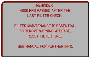 | A note of precaution when cleaning the air filter.Please immediately turn the power off, and clean or change the air filter referring to theCleaning and replacing the air filtersection of this manual. After you have cleaned or changed the air filter, please be sure to reset the filter timer. |
 | The button operation is not available. |
Regarding the indicator lamps
When operation of the LAMP, TEMP and POWER indicators differs from usual, check and cope with it according to the following table.
For the SECURITY indicator, see SECURITY INDICATOR in the SECURITY menu.
NOTE • When the interior portion has become overheated, for safety purposes, the projector is automatically shut down, and the indicator lamps may also be turned off. In such a case, disconnect the power cord, and wait at least 45 minutes. After the projector has sufficiently cooled down, please make confirmation of the attachment state of the lamp and lamp cover, and then turn the power on again.
| POWER indicator | LAMP indicator | TEMP indicator | Description |
| Lighting In Orange | Turned off | Turned off | The projector is in a standby state.Please refer to the section “Power on/off”. |
| Blinking In Green | Turned off | Turned off | The projector is warming up.Please wait. |
| Lighting In Green | Turned off | Turned off | The projector is in an on state. Ordinary operations may be performed. |
| Blinking In Orange | Turned off | Turned off | The projector is cooling down.Please wait. |
| Blinking In Red | (discretionary) | (discretionary) | The projector is cooling down. A certain error has been detected.Please wait until POWER indicator finishes blinking, and then perform the proper measure using the item descriptions below. |
| Blinking In Red or Lighting In Red | Lighting In Red | Turned off | The lamp does not light, and there is a possibility that interior portion has become heated.Please turn the power off, and allow the projector to cool down at least 20 minutes. After the projector has sufficiently cooled down, please make confirmation of the following items, and then turn the power on again.Is there blockage of the air passage aperture?Is the air filter dirty?Does the peripheral temperature exceed 35°C?If the same indication is displayed after the remedy, please change the lamp referring to the section Replacing the lamp. |
| Blinking In Red or Lighting In Red | Blinking In Red | Turned off | The lamp cover has not been properly fixed.Please turn the power off, and allow the projector to cool down at least 45 minutes. After the projector has sufficiently cooled down, please make confirmation of the attachment state of the lamp cover. After performing any needed maintenance, turn the power on again.If the same indication is displayed after the remedy, please contact your dealer or service company. |
| Blinking In Red or Lighting In Red | Turned off | Blinking In Red | The cooling fan is not operating.Please turn the power off, and allow the projector to cool down at least 20 minutes. After the projector has sufficiently cooled down, please make confirmation that no foreign matter has become caught in the fan, etc., and then turn the power on again.If the same indication is displayed after the remedy, please contact your dealer or service company. |
| Blinking In Red or Lighting In Red | Turned off | Lighting In Red | There is a possibility that the interior portion has become heated.Please turn the power off, and allow the projector to cool down at least 20 minutes. After the projector has sufficiently cooled down, please make confirmation of the following items, and then turn the power on again.Is there blockage of the air passage aperture?Is the air filter dirty?Does the peripheral temperature exceed 35°C?Is the setting for FAN SPEED appropriate?For details on FAN SPEED, refer to FAN SPEED of SERVICE in the OPTION menu. If the projector is used with a wrong setting, it may cause damage to the projector itself or the parts inside. |
| Lighting In Green | Simultaneous blinking in Red | It is time to clean the air filter.Please immediately turn the power off, and clean or change the air filter referring to the section Cleaning and replacing the air filter. After cleaning or changing the air filter, please be sure to reset the filter timer. After the remedy, reset the power to ON. | |
| Lighting In Green | Alternative blinking in Red | There is a possibility that the interior portion has become overcooled.Please use the unit within the usage temperature parameters (5°C to 35°C).After the treatment, reset the power to ON. | |
| Blinking In Green for approx. 3 seconds. | Turned off | Turned off | At least 1 Power ON schedule is saved to the projector.Please refer to 3.7 Schedule Settings in the Network Guide. |
Shutting the projector down
Only when the projector can not be turned off by usual procedure, please push the shutdown switch using a pin or similar, and disconnect the power plug from the power outlet. Before turning it on again, wait at least 10 minutes to make the projector cool down enough.
Resetting all settings
When it is hard to correct some wrong settings, the FACTORY RESET function of SERVICE item in OPTION menu can reset all settings (except settings such as LANGUAGE, LAMP TIME, FILTER TIME, FILTER MESSAGE, SECURITY and NETWORK) to the factory default.
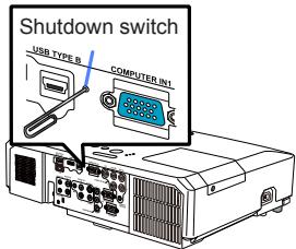
text_image
Shutdown switch USB TYPE B COMPUTER.IN1Phenomena that may be easy to be mistaken for machine defects
About the phenomenon confused with a machine defect, check and cope with it according to the following table.
| Phenomenon | Cases not involving a machine defect | Reference page |
| Power does not come on. | The electrical power cord is not plugged in.Correctly connect the power cord. | 15 |
| The main power source has been interrupted during operation such as by a power outage (blackout), etc.Please disconnect the power plug from the power outlet, and allow the projector to cool down at least 10 minutes, then turn the power on again. | 15 | |
| Either there is no lamp and/or lamp cover, or either of these has not been properly fixed.Please turn the power off and disconnect the power plug from the power outlet, and allow the projector to cool down at least 45 minutes. After the projector has sufficiently cooled down, please make confirmation of the attachment state of the lamp and lamp cover, and then turn the power on again. | 89 | |
| Neither sounds nor pictures are outputted. | The signal cables are not correctly connected.Correctly connect the connection cables. | 10 ~ 14 |
| Signal source does not correctly work.Correctly set up the signal source device by referring to the manual of the source device. | - | |
| The input changeover settings are mismatched.Select the input signal, and correct the settings. | 19 ~ 21 | |
| The BLANK function for pictures and the MUTE function for sounds are working.AV MUTE may be active.Refer to the item “Sound does not come out” and “No pictures are displayed” on the next page to turn off the MUTE and BLANK functions. | 19, 28, 100 | |
| Sound does not come out. | The signal cables are not correctly connected.Correctly connect the audio cables. | 10 ~ 14 |
| The MUTE function is working.Restore the sound pressing MUTE or VOLUME +/- button on the remote control. | 19 | |
| The volume is adjusted to an extremely low level.Adjust the volume to a higher level using the menu function or the remote control. | 19, 46, 47 | |
| The AUDIO SOURCE/SPEAKER setting is not correct.Correctly set the AUDIO SOURCE/SPEAKER in AUDIO menu. | 46 | |
| The mode selected for HDMI AUDIO is not suitable.Check each of the two modes provided and select the suitable one for your HDMITM audio device. | 47 | |
| No pictures are displayed. | The lens cover is attached.Remove the lens cover. | 4, 18 |
| The signal cables are not correctly connected.Correctly connect the connection cables. | 10 ~ 14 | |
| The brightness is adjusted to an extremely low level.Adjust BRIGHTNESS to a higher level using the menu function. | 33 | |
| The computer cannot detect the projector as a plug and play monitor.Make sure that the computer can detect a plug and play monitor using another plug and play monitor. | 10 | |
| The BLANK screen is displayed.Press BLANK button on the remote control. | 28 | |
| The USB TYPE B port is selected as the picture input source even if MOUSE is selected for USB TYPE B.Select USB DISPLAY for USB TYPE B in OPTION menu to project the picture input to the port. Otherwise select other port for picture input. | 55 | |
| The projector does not recognize the USB storage device inserted into USB TYPE A port.Use the REMOVE USB function first, remove the USB storage device, and then insert it into the port again.Before removing the USB storage device, be sure to use the REMOVE USB function on the thumbnail screen, which appears when the USB TYPE A port is selected as the input source. | 12, 80 | |
| Video screen display freezes. | The FREEZE function is working.Press FREEZE button to restore the screen to normal. | 28 |
| Colors have a faded-out appearance, or Color tone is poor. | Color settings are not correctly adjusted.Perform picture adjustments by changing the COLOR TEMP, COLOR, TINT and/or COLOR SPACE settings, using the menu functions. | 34, 39 |
| COLOR SPACE setting is not suitable.Change the COLOR SPACE setting to AUTO, RGB, SMPTE240, REC709 or REC601. | 39 | |
| Pictures appear dark. | The brightness and/or contrast are adjusted to an extremely low level.Adjust BRIGHTNESS and/or CONTRAST settings to a higher level using the menu function. | 33 |
| The projector is operating in Eco mode.Set ECO MODE to NORMAL, and set AUTO ECO MODE to OFF, in the SETUP menu. | 44 | |
| The lamp is approaching the end of its product lifetime.Replace the lamp. | 89 ~ 90 | |
| Pictures appear blurry. | Either the focus and/or horizontal phase settings are not properly adjusted.Adjust the focus using the focus ring, and/or H PHASE using the menu function. | 23, 38 |
| The lens is dirty or misty.Clean the lens referring to the section Caring for the lens. | 94 | |
| Some kind of image degradation such as flickering or stripes appear on screen. | When the projector is operating in Eco mode, flickering may appear on screen.Set ECO MODE to NORMAL, and set AUTO ECO MODE to OFF, in the SETUP menu. | 44 |
| The OVER SCAN ratio is too big.Adjust OVER SCAN in the IMAGE menu smaller. | 36 | |
| Excessive VIDEO NR.Change the setting of VIDEO NR in the INPUT menu. | 39 | |
| The FRAME LOCK function cannot work on the current input signal.Set FRAME LOCK in the INPUT menu to OFF. | 41 | |
| The computer connected to the USB TYPE B port of the projector does not start up. | The computer cannot start up in the current hardware configuration.Disconnect the USB cable from the computer, then reconnect it after starting up the computer. | 12 |
| RS-232C does not work. | The SAVING function is working.Select NORMAL for STANDBY MODE item in the SETUP menu. | 45 |
| The COMMUNICATION TYPE for the CONTROL port is set to NETWORK BRIDGE.Select OFF for COMMUNICATION TYPE item in the OPTION - SERVICE - COMMUNICATION menu. | 61 | |
| Network does not work | The SAVING function is working.Select NORMAL for STANDBY MODE item in the SETUP menu. | 45 |
| NETWORK BRIDGE function does not work | The NETWORK BRIDGE function is turned off.Select NETWORK BRIDGE for COMMUNICATION TYPE item in the OPTION - SERVICE - COMMUNICATION menu. | 61 |
| Schedule function does not work | The SAVING function is working.Select NORMAL for STANDBY MODE item in the SETUP menu. | 45 |
| When the projector is connected to the network, it powers off and on as described below.Powers off←↓POWER indicator blinks in orange a few times↓Goes into standby mode | Disconnect the LAN cable and check that the projector is working properly.If this phenomenon occurs after connecting to the network, there may be a loop between two Ethernet switching hubs within the network, as explained below.- There are two or more Ethernet switching hubs in a network.- Two of the hubs are doubly connected by LAN cables.- This double connection forms a loop between the two hubs.Such a loop may have an adverse effect on the projector as well as the other network devices.Check the network connection and remove the loop by disconnecting the LAN cables such that there is only one connecting cable between two hubs. | – |
| Video files cannot be played properly on a computer on which the "LiveViewer" was run. | The "LiveViewer" has been intentionally or accidentally forced to shut down.DirectDraw® or Direct3D® has been disabled on your Windows®.Please refer to the Microsoft® Help and Support home page on how to enable DirectDraw® or Direct3D®. | – |
NOTE • Although bright spots or dark spots may appear on the screen, this is a unique characteristic of liquid crystal displays, and it does not constitute or imply a machine defect.
Specifications
| Item | Specification |
| Product name | Liquid crystal projector |
| Liquid Crystal Panel | 786,432 pixels (1024 horizontal x 768 vertical) |
| Lamp | 245 W UHP |
| Speaker | 16 W mono (8 W x2) |
| Power supply/Rated current | AC100-120 V: 4.0 A, AC220-240 V: 2.0 A |
| Power consumption | AC100-120 V: 380 W, AC220-240 V: 360 W |
| Temperature range | 5 ~ 35 °C (Operating) |
| Size | 401 (W) x 103 (H) x 318 (D) mm* Not including protruding parts. |
| Weight (mass) | approx. 4.6 kg |
| Ports | COMPUTER IN1 ...... D-sub 15 pin mini jack x1COMPUTER IN2 (H, V, G/Y, B/Cb/Pb, R/Cr/Pr) ... BNC jack x5HDMI ...... HDMI connector x1MONOTOR OUT ...... D-sub 15 pin mini jack x1COMPONENT (Y, Cb/Pb, Cr/Pr) ...... RCA jack x3S-VIDEO ...... Mini DIN 4 pin jack x1VIDEO ...... RCA jack x1AUDIO IN1 ...... 3.5 mm (stereo) mini jack x1AUDIO IN2 ...... 3.5 mm (stereo) mini jack x1AUDIO IN3 (R, L) ...... RCA jack x2AUDIO OUT (R, L) ...... RCA jack x2USB TYPE A ...... USB type A connector x1USB TYPE B ...... USB type B connector x1CONTROL ...... D-sub 9 pin plug x1LAN ...... RJ45 jack x1MIC ...... 3.5 mm (mono) mini jack x1REMOTE CONTROL ...... 3.5 mm (stereo) mini jack x1 |
| Optional parts | Lamp: RLC-063 (DT01175)* For more information, please consult your dealer. |
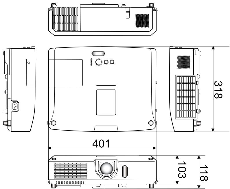
text_image
318 401 103 118[unit: mm]
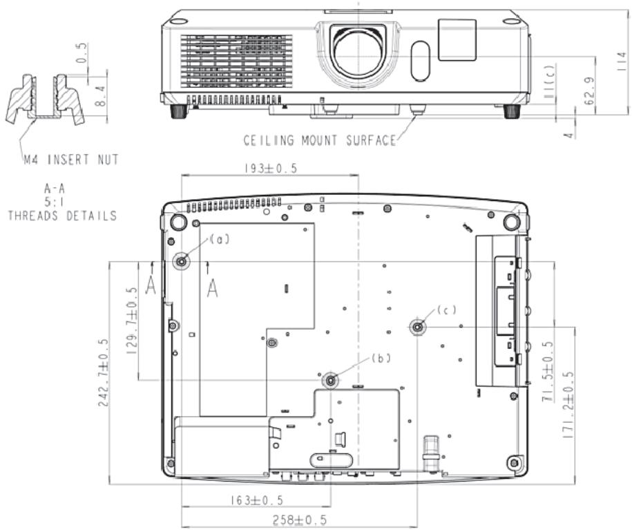
text_image
0.5 8.4 M4 INSERT NUT A-A 5:1 THREADS DETAILS CEILING MOUNT SURFACE 193±0.5 (a) 242.7±0.5 129.7±0.5 (c) (b) 163±0.5 258±0.5 11(c) 62.9 114 171.2±0.5 71.5±0.5Network Guide
1. Connection to the network
1.1 System requirements
1.1.1 Required equipment preparation
The following equipments are required to connect the projector to your computer through the network.
√ Projector
√ LAN cable (to connect the projector to a network): CAT-5 or greater
√ Computer (minimum 1 set): equipped with the network feature (100Base-TX or 10Base-T)
1.1.2 Hardware and software requirement for computer
The “LiveViewer” software needs to be installed on all the computers to connect to the projector through a network. To use the “LiveViewer” your computer needs to meet the following requirements.
√ OS: One of the following.
Windows ^® XP Home Edition /Professional Edition (32 bit version only)
Windows Vista ^® Home Basic /Home Premium /Business /Ultimate /Enterprise (32 bit version only)
Windows ^® 7 Starter /Home Basic /Home Premium /Professional /Ultimate /Enterprise (32 bit version only)
√ CPU: Pentium 4 (2.8 GHz or higher)
√ Graphic card: 16 bit, XGA or higher
* When using the “LiveViewer” it is recommended that the display resolution of your computer is set to 1024 x 768.
√ Memory: 512 MB or higher
√ Hard disk space: 100 MB or higher
√ Web browser: Internet Explorer ^® 6.0 or higher
√ CD-ROM drive
NOTE • The network communication control is disabled while the projector is in standby mode if the STANDBY MODE item is set to SAVING. Please connect the network communication to the projector after setting the STANDBY MODE to NORMAL. (SETUP menu in the Operating Guide)
- You can get the latest version of the “LiveViewer” and the latest information for this product from our website.
- Depending on the specification of your computer, the computer may slow down due to high CPU usage when the “LiveViewer” is running.
- The “LiveViewer” does not work on Windows Vista® that is not updated to Service Pack 1 or later. Please install the latest Service Pack on your Windows Vista®.
1.1 System requirements (continued)
NOTE • Referring to the manual of your computer or Windows, select the following or a smaller display resolution for the computer.
1024 x 768 (XGA)
When a resolution larger than the specified resolution is selected, the projector will convert and display in the specified resolution, and the display speed may become faster. If your computer does not support the display resolution specified above, a smaller resolution that is the largest among the resolutions that are supported by the computer will be selected.
- Images might not been transmitted, caused by OS version or the driver software for Network Adapter on your computers. It is highly recommended that OS and the driver should be updated to the latest.
- If any application software having the firewall function is installed into you computer, make the firewall function invalid with following the user's manual.
1.2 Installing the "LiveViewer"
1.2.1 Installing the "LiveViewer"
The “LiveViewer” software needs to be installed on all the computers to connect to the projector through a network.
You need to log in as an administrator user to install the software.
1) Turn on the computer.
2) Shut down all applications.
3) Insert the accompanying CD-ROM into the computer's CD-ROM drive.
4) Click on the [Start] button on the toolbar and select the "Run".
5) Enter E:\Application\LiveViewer\LiveViewer_Setup.exe and then press the [OK].
If your CD-ROM drive is not drive E on your computer, you will need to replace E with the correct drive letter assigned to your CD-ROM drive.
6) After a moment, the Choose Setup Language dialog will appear as shown on the right. Select what you like to use in the list, and click the [OK].

text_image
Choose Setup Language Select the language for the installation from the choices below. English OK CancelIf the software has been already installed, Uninstallation will be done. Click the [Cancel] button, then uninstallation will be canceled. If you uninstalled the software by miss-operation, please re-install the software from first procedure.
7) After a moment, the Welcome dialog will appear as shown on the right. Press the [Next].
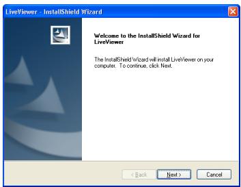
text_image
LiveViewer InstallShield Wizard Welcome to the InstallShield Wizard for LiveViewer The InstallShield Wizard will install LiveViewer on your computer. To continue, click Next. < Back Next > Cancel1.2 Installing the "LiveViewer" (continued)
8) The License Agreement dialog appears. If you accept it, select "I accept the terms of the license agreement" and press the [Next].
9) The Choose Destination Location dialog appears. Press the [Next].
NOTE • The C:\Program Files\Projector Tools\LiveViewer folder will be created and the program will be installed into that folder. If you wish to install to a different folder, click the [Browse] and select another folder.
10) Confirm the program folder name. If "Projector Tools" is okay, press the [Next] to continue. If not, enter the desired folder name and then press the [Next].
11) [Windows ^® XP]
The Hardware Installation dialog appears if you are using Windows ^® XP. Press Continue Anyway.
[Windows Vista ^® or Windows ^® 7] The Windows Security dialog will appear if you are using Windows Vista ^® or Windows ^® 7. Please click the [Install this driver software anyway] and continue installation.
12) After a moment, installation will complete and the Setup Complete dialog will appear as shown on the right. Click the [Finish]. This completes the software installation. Then your computer automatically restarts.
(1) To confirm that the software has been properly installed, press the [Start] button on the toolbar, select All Programs and then select the Projector Tools folder.
(2) The “LiveViewer” will appear in that folder if the installation was successful.
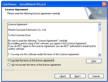
text_image
LiveViewer InstallShield Wizard License Agreement Please read the following license agreement carefully. License Agreement Hitachi Consumer Electronics Co., Ltd. To the Customer/User: Be sure to read the following "License Agreement" carefully. By installing and/or using of this software, you agree to this License Agreement. If you do NOT agree to the License Agreement, you are NOT authorized to install and/or use this software. 1. You may use this software under the terms of this License Agreement. ○ I accept the terms of the license agreement ○ I do not accept the terms of the license agreement Next < Back Next > Cancel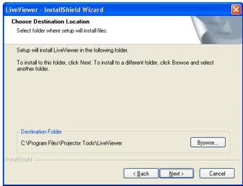
text_image
LiveViewer - InstallShield Wizard Choose Destination Location Select folder where setup will install files. Setup will install LiveViewer in the following folder. To install to this folder, click Next. To install to a different folder, click Browse and select another folder. Destination Folder C:\Program Files\Projector Tools\LiveViewer Browse... < Back Next > Cancel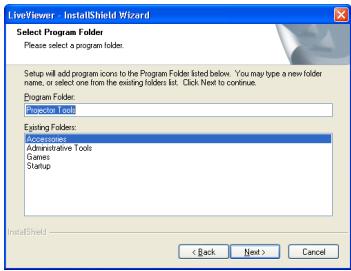
text_image
LiveViewer InstallShield Wizard Select Program Folder Please select a program folder. Setup will add program icons to the Program Folder listed below. You may type a new folder name, or select one from the existing folders list. Click Next to continue. Program Folder: Accessories Existing Folders: Accessories Administrative Tools Games Startup < Back Next > Cancel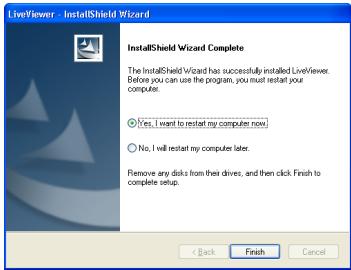
text_image
LiveViewer InstallShield Wizard InstallShield Wizard Complete The InstallShield Wizard has successfully installed LiveViewer. Before you can use the program, you must restart your computer. Yes, I want to restart my computer now. No, I will restart my computer later. Remove any disks from their drivers, and then click Finish to complete setup. < Back Finish Cancel1.3 Process to connect the network
Before connecting your computer and projector via a network, make sure that the LAN port is selected as the input source on the projector. (Operating in the Operating Guide) Otherwise a connection cannot be established.
1.3.1 Process overview
An overview of the process to connect your computer and the projector via a network is shown below.
The “LiveViewer” allows you to skip some of the steps below to establish a network connection quickly and easily.
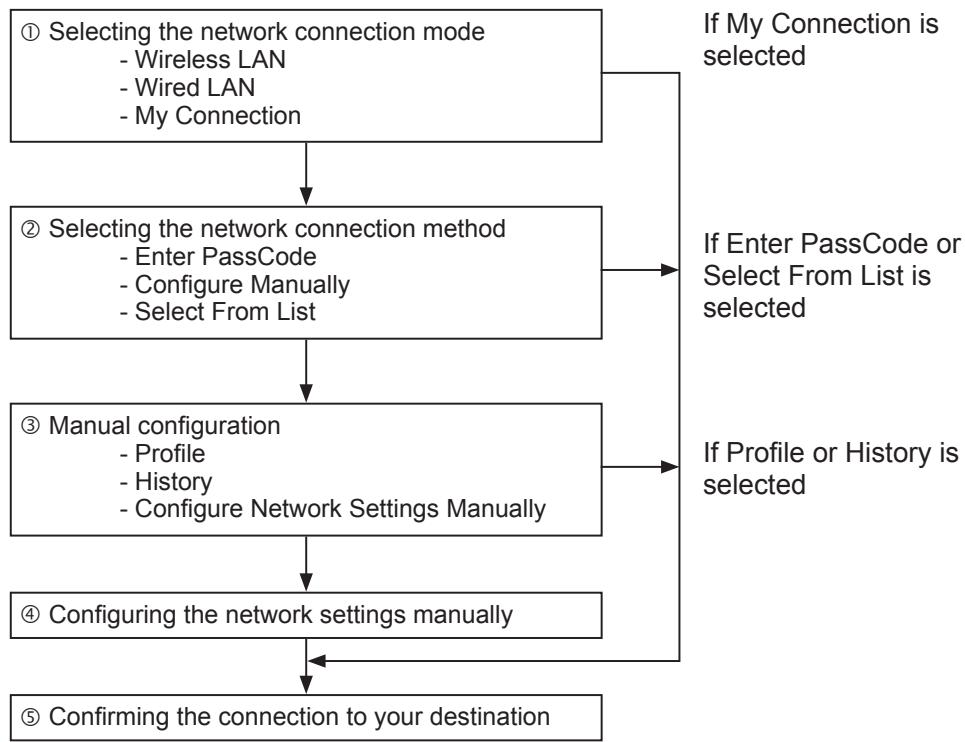
flowchart
graph TD
    A["① Selecting the network connection mode\n- Wireless LAN\n- Wired LAN\n- My Connection"] --> B["② Selecting the network connection method\n- Enter PassCode\n- Configure Manually\n- Select From List"]
    B --> C["③ Manual configuration\n- Profile\n- History\n- Configure Network Settings Manually"]
    C --> D["④ Configuring the network settings manually"]
    D --> E["⑤ Confirming the connection to your destination"]
    A --> F["If My Connection is selected"]
    B --> G["If Enter PassCode or Select From List is selected"]
    C --> H["If Profile or History is selected"]
    D --> I["Confirming the connection to your destination"]
NOTE • Wireless LAN can be selected only when an access point to convert wireless LAN to wired LAN exists between your computer and the projector. • Up to 30 computers can be simultaneously connected to the projector through a network.
1.3 Process to connect the network (continued)
1.3.2 Starting the "LiveViewer"
Start the “LiveViewer” in your computer, taking one of the followings.
- Double click the "LiveViewer" icon on the Desktop in your computer
- Select "Start" → "All Programs" → "Projector Tools" → "LiveViewer" on Windows menu.
Then, proceed to item 1.4 Selecting the network connection mode.
1.4 Selecting the network connection mode
After starting the “LiveViewer”, the “Select the Network Connection” screen comes up.
Select the network connection that you would like to use. There are 3 options in the menu.
- Wireless LAN
- Wired LAN
- My Connection
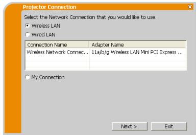
text_image
Projector Connection Select the Network Connection that you would like to use. ● Wireless LAN ○ Wired LAN Connection Name Adapter Name Wireless Network Connec... 11a/b/g Wireless LAN Mini PCI Express ... My Connection Next > ExitIf you select either the wireless LAN or wired LAN, proceed to item 1.4.1 Selecting either the wireless LAN or wired LAN.
If you select My Connection, jump to item 1.4.2 Selecting My Connection.
NOTE • Select Wireless LAN only when you connect the computer and the access point via wireless network and connect the access point and the projector via wired network, since the projector doesn't have wireless LAN function.
1.4.1 Selecting either the wireless LAN or wired LAN
If you select either the wireless LAN or wired LAN, a list of the network adapters in your computer is shown in the menu.
Select what you like to use in the list, and click the [Next].
Then, proceed to item 1.5 Selecting the network connection method.
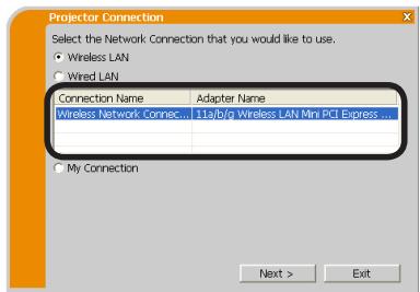
text_image
Projector Connection Select the Network Connection that you would like to use. • Wireless LAN • Wired LAN Connection Name Adapter Name Wireless Network Connec... 11a/b/g Wireless LAN Mini PCI Express ... My Connection Next > ExitNOTE • If you select the wireless LAN, the wireless LAN adapters in your computer are shown in the list.
- If the wired LAN is selected, the wired LAN adapters in your computer are shown.
[Troubleshooting]
■ Are you sure that you want to turn on the network adapter?
The screen is displayed in the case that the selected network adapter is invalid.
- To turn it on, click the [Yes], and then proceed to item 1.5.
- Not to turn it on, click the [No], and then the screen is back to the previous one to select another network adapter.
![VIEWSONIC PRO9500 - [Troubleshooting] - 1](/content/2025/01/170018/images/d378a77c36ff950ad5a54439766551271e437fcacc21067d79643d301c47fc42.jpg)
text_image
Projector Connection Are you sure that you want to turn on the network adapter? Yes No1.4 Selecting the network connection mode (continued)
■ A network connection was not established.
The screen is displayed in the case that the projector is not connected with a LAN cable to your computer when the wired LAN is selected.
Be sure that the projector is connected with a LAN cable to your computer.
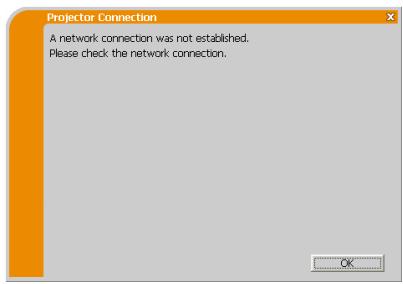
text_image
Projector Connection A network connection was not established. Please check the network connection.Click the [OK], then the screen is back to the previous one to select the network connection mode.
1.4 Selecting the network connection mode (continued)
1.4.2 Selecting My Connection
Select the [My Connection] and click the [Connect].
If you select the My Connection, the computer is connected to the projector through the network by using the profile data that is pre-assigned to My Connection. When you select the My Connection, the computer immediately starts the connection to the projector.
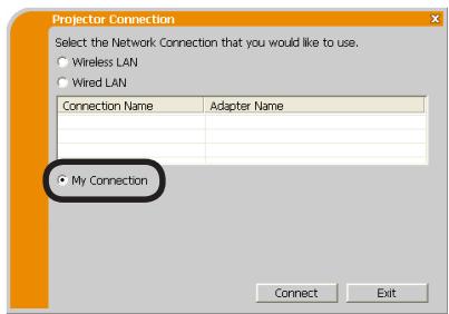
text_image
Projector Connection Select the Network Connection that you would like to use. Wireless LAN Wired LAN Connection Name Adapter Name My Connection Connect ExitProceed to item 1.8 Confirming the connection to your destination.
NOTE • If the DHCP is set on in the projector, the network connection between the projector and computer may not be established since IP address may be varied. If you like to use the My Connection, set the DHCP off in the projector.
- If no profile data is assigned to the My Connection, it can't be used.
[Troubleshooting]
■ A network connection could not be established.
Windows prevented network configuration changes.
You may log in the Windows under User authority.
Click the [OK] to return to the screen to select the network connection mode.
![VIEWSONIC PRO9500 - [Troubleshooting] - 1](/content/2025/01/170018/images/68488439f15b852d421c14be4d19e68be71b570aa2881b0029e233ff0910349d.jpg)
text_image
Projector Connection A network connection could not be established. Windows prevented network configuration changes. Please insure that you are authorized to make these changes or check your security settings.Consult to the network administrator and log in again under the Administrator authority. After that, please resume at item 1.3.2 Starting the “LiveViewer”.
1.4 Selecting the network connection mode (continued)
■ Are you sure you want to connect the selected projector?
The message is appeared when the wireless adapter you selected is already used for another network connection.
- To connect, click the [Yes]. Proceed to item 1.8 Confirming the connection to your destination.
- Not to connect, click the [No] to return to the screen to select the network connection mode.
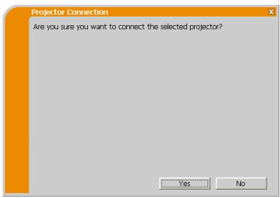
text_image
Projector Connection Are you sure you want to connect the selected projector? Yes No1.5 Selecting the network connection method
There are some options to connect to the network.
- Enter PassCode
- Configure Manually
- Select From List
Select one of them to meet your requirement.
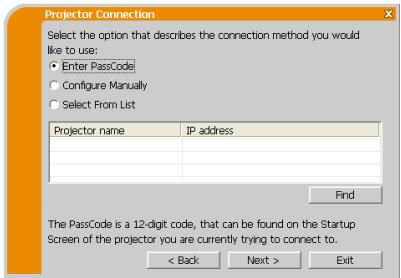
text_image
Projector Connection Select the option that describes the connection method you would like to use: • Enter PassCode • Configure Manually • Select From List Projector name JP address Find The PassCode is a 12-digit code, that can be found on the Startup Screen of the projector you are currently trying to connect to. < Back Next > ExitEnter PassCode
If you want to use the Passcode for network connection, select the [Enter PassCode] and click the [Next].
The Passcode is given by the projector on screen. And you simply input the Passcode to the “LiveViewer” to connect the network.
Proceed to item 1.5.1 Passcode connection.
Configure Manually
Select the [Configure Manually] and click the [Next].
Then, proceed to item 1.6 Manual Configuration.
Select From List
Before selecting this item, your computer and the projectors need to be connected to the same network.
If the connection is already established, select the [Select From List].
From the list of the projectors connected to the network, select which projector you would like to send your images. Proceed to 1.8 Confirming the connection to your destination.
1.5 Selecting the network connection method (continued)
1.5.1 Passcode connection
The unique Passcode system brings you very quick and simple connection to the network.
The Passcode is a code that expresses the network setting in the projector. If you input the code in the “LiveViewer” in your computer, the network setting in the projector and computer can be matched and the connection will be established immediately. The section is intended to explain how to use the Passcode.
(1) Getting the Passcode
The Passcode is 12-digit code consisting of alphanumeric characters (“1-9” and “A-Z”).
Example: PASSCODE 1234-5678-9ABC
The Passcode is given on the projector when the LAN port is selected as input source.
NOTE • The Passcode system does not work under the condition below. If such is the case, establish the connection manually.
1) Subnet mask is not Class A or B or C.
The Passcode system accepts Class A, B and C only.
Class A:(255.0.0.0), Class B:(255.255.0.0), Class C:(255.255.255.0)
There are two methods to get the Passcode from the projector
Method 1
1) Turn on the projector, and make sure that the projector image is on screen.
2) Press the COMPUTER button on the remote control or INPUT button on the projector to select the LAN as input port.
If there is no signal on the LAN port, you can find the Passcode on screen.
1.5 Selecting the network connection method (continued)
Method 2
1) Turn on the projector, and make sure that the projector image is on screen.
2) Press the MENU button on the remote control or the ▲/▼ buttons on the projector to show the menu on screen.
3) Use the ▲/▼ cursor buttons to select the “ADVANCED MENU”, and use the ▶ cursor button to enter the item.
4) Use the ▲/▼ cursor buttons to select the NETWORK, and use the ▶ cursor button to enter the item.
5) Use the ▲/▼ cursor buttons to select the INFORMATION, and use the ▶ cursor button to display the INFORMATION.
6) The Passcode appears in the INFORMATION window.
NOTE • Take the method 2 when you project your computer image by the "LiveViewer", or when the LAN port is not selected as input source.
- If no communication between the projector and computer in 5 minutes, the Passcode will be changed.
1.5 Selecting the network connection method (continued)
(2) Entering the Passcode
If you select [Enter PassCode] at item 1.5, the "Please enter the PassCode" screen is displayed. Please enter the Passcode divided 4-digit each in 3 boxes (total 12-digit).
Example PASSCODE: 1234 - 5678 - 9ABC
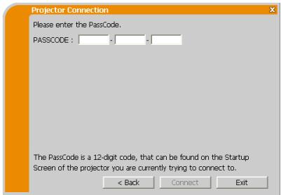
text_image
Projector Connection Please enter the PassCode. PASSCODE : The PassCode is a 12-digit code, that can be found on the Startup Screen of the projector you are currently trying to connect to. < Back Connect ExitAfter entering the Passcode, click the [Connect] to start the connection to the projector.
Proceed to item 1.8 Confirming the connection to your destination.
If you click the [Back], the screen is back to item 1.5 Selecting the network connection method.
NOTE • When entering the Passcode, capital and small letters are not distinguished.
- If you are using a Subnet mask other than Class A, B or C, you will have to establish the connection manually.
If the manual setting screen is displayed, please follow item 1.5.1 (3).
[Troubleshooting]
■ Incorrect PassCode.
The incorrect Passcode was input.
Click the [Back] to return to the "Please enter the PassCode" screen.
Check the PassCode on the projector screen and enter the code again.
![VIEWSONIC PRO9500 - [Troubleshooting] - 1](/content/2025/01/170018/images/4b655a34d798f173a041d9f574ff50da787adc1e19e133fc4acaa2e9022ea582.jpg)
text_image
Projector Connection Incorrect PassCode. PASSCODE : 1234 - 5678 - 9ABC < Back Exit1.5 Selecting the network connection method (continued)
■ A network connection could not be established.
Windows prevented network configuration changes.
You may log in the Windows under User authority.
Click the [OK], then the "LiveViewer" main menu is displayed even though the network is not established. Click 📄 on the main and go back to item 1.5 Selecting the network connection method.
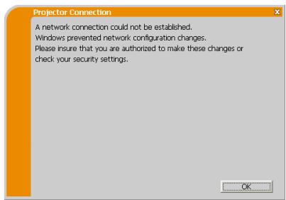
text_image
Projector Connection A network connection could not be established. Windows prevented network configuration changes. Please insure that you are authorized to make these changes or check your security settings.Consult to the network administrator. Log in the Windows under Administrator authority. After that, please resume at item 1.3.2 Starting the “LiveViewer”.
■ If you need to add a Network configuration on your computer to connect to the projector.
This dialog will be displayed when you need to add a Network configuration on your computer to connect to the projector. Confirm with your network administrator if the Network configuration displayed on the dialog is OK, and then click the [Yes].
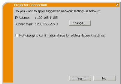
text_image
Projector Connection Do you want to apply suggested network settings as follows? IP Address : 192.168.1.105 Subnet mask : 255.255.255.0 Change... Not displaying confirmation dialog for adding Network settings. Yes NoClick the [NO], then the "LiveViewer" main menu is displayed even though the network is not established. Click 📄 on the main menu and go back to item 1.5 Selecting the network connection method.
1.5 Selecting the network connection method (continued)
If you put a check mark in the box “Not displaying confirmation dialog for adding Network settings”, the projector memorizes current configuration and this dialog is not displayed again. To display this dialog again, click Option 🔒 icon in the “LiveViewer” main menu and remove the check mark in the box “Not displaying confirmation dialog for adding Network settings”.
If you want to change the Network configuration to add, click the [Change]. A dialog for changing the Network configuration as shown to the right will be displayed. Enter IP address and subnet mask, then click the [OK]. Procedure to connect to the projector will start.
Proceed to item 1.8 Confirming the connection to your destination.
If you click the [Cancel], you will return to the dialog for adding a Network configuration.
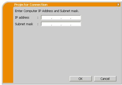
text_image
Projector Connection Enter Computer IP Address and Subnet mask. IP address : . . . . Subnet mask : . . . . OK CancelIf the entered IP address and projector's IP address are the same, a warning dialog shown to the right will be displayed.
Click the [OK], and then enter a different IP address from the projector's one in the dialog for changing Network configuration.

text_image
Projector Connection An IP Address overlaps with the IP Address of the projector you are trying to connect to. Please choose an IP Address that is currently not in use.If the connection is not available with the entered Network configuration, a warning dialog shown to the right will be displayed. Click the [OK] to return to the dialog for changing the Network configuration, and then enter appropriate configuration.
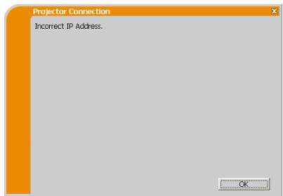
text_image
Projector Connection Incorrect IP Address. OKNOTE • If a Network configuration to connect to the projector has been added on the computer, the added Network configuration will be erased once the application software is closed.
1.5 Selecting the network connection method (continued)
■ Are you sure you want to connect the selected projector?
The message is appeared when the wireless adapter you selected is already used for another network connection.
- To connect, click the [Yes]. Proceed to item 1.8 Confirming the connection to your destination.
- Not to connect, click the [No] then the "LiveViewer" main menu is displayed even though the network is not established. Click 📄 on the main menu to go back to item 1.5 Selecting the network connection method.
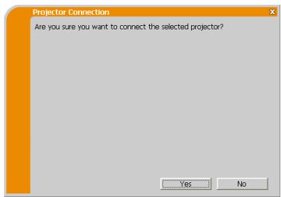
text_image
Projector Connection Are you sure you want to connect the selected projector? Yes No1.5 Selecting the network connection method (continued)
(3) Configuring manually
After entering the Passcode, you are required to enter the network configuration manually if you use a Subnet mask other than Class A, B or C.
Wireless LAN
The projector is required to be connected to an access point by a LAN cable.
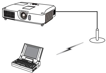
natural_image
Illustration of a projector connected to a laptop and a power cord (no text or symbols)1) The setting on the access point. *1 Enter the following information.
SSID : WirelessAccessPoint (example)
Encryption: WEP64bit (example)
Encryption key *2: ********** (example)
2) The setting on the projector. *3
Enter the following information.
Subnet mask *4: 255.255.255.128
(example)
3) Click the [Connect].
4) The wireless connection will be established.
Proceed to item 1.8 Confirming the connection to your destination.
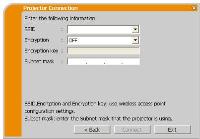
text_image
Projector Connection Enter the following information. SSID : Encryption : OFF Encryption key : Subnet mask : . SSID,Encryption and Encryption key: use wireless access point configuration settings. Subset mask: enter the Subnet mask that the projector is using. < Back Connect Exit*1 Contact the network administrator to find out the setting on the access point.
*2 If you use an encryption, you need to set it. Contact the network administrator to check the encryption key that is set in the projector.
The encryption key is always shown as “**********”.
*3 To find the network setting on the projector, refer to the NOTE.
*4 If you use Subnet mask except Class A/B/C, please set it.
1.5 Selecting the network connection method (continued)
Wired LAN
1) Enter the following information for the projector.
Subnet mask *1: 255.255.255.128 (example)
2) Click the [Connect].
3) The network connection will be established. Proceed to item 1.8 Confirming the connection to your destination.
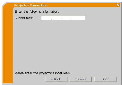
text_image
Projector Connection Enter the following information. Subnet mask : . . . Please enter the projector subnet mask. < Back Connect Exit*1 If you use a Subnet mask other than Class A, B or C, this screen appears.
NOTE • If you require the network setting information on the projector, take the following procedure to find it out.
1) Turn on the projector, and make sure that the projector image is on screen.
2) Press the MENU button on the remote control or the ▲/▼ buttons on the projector to show the menu on screen.
3) Use the ▲/▼ cursor buttons to select the “ADVANCED MENU”, and use the ▶ cursor button to enter the item.
4) Use the ▲/▼ cursor buttons to select the NETWORK, and use the ▶ cursor button to enter the item.
5) Use the ▲/▼ cursor buttons to select the INFORMATION, and push the ▶ cursor button.
6) The setting will be displayed in the NETWORK_INFORMATION-box.
1.6 Manual configuration
There are 3 options for the manual configuration.
- Profile
- History
- Configure Network Settings Manually
If you select Configure Network Settings Manually, proceed to item 1.7 Configuring the network settings manually.
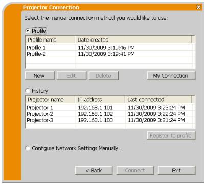
text_image
Projector Connection Select the manual connection method you would like to use: Profile Profile name Date created Profile-1 11/30/2009 3:19:46 PM Profile-2 11/30/2009 3:19:41 PM New Edit Delete My Connection History Projector name IP address Last connected Projector-1 192.168.1.101 11/30/2009 3:23:24 PM Projector-2 192.168.1.102 11/30/2009 3:22:24 PM Projector-3 192.168.1.103 11/30/2009 3:21:24 PM Register to profile Configure Network Settings Manually. < Back Connect Exit1.6.1 Profile connection
Selecting a profile data connect the network with the projector.
It is required to store the profile data in advance.
1) Select the [Profile].
2) Choose a profile data listed in the window.
3) Click the [Connect].
4) The network connection will be established. Proceed to item 1.8 Confirming the connection to your destination.
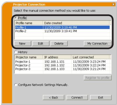
text_image
Projector Connection Select the manual connection method you would like to use: Profile Profile name Date created Profile-1 11/30/2009 3:19:46 PM Profile-2 11/30/2009 3:19:41 PM New Edit Delete My Connection History Projector name IP address Last connected Projector-1 192.168.1.101 11/30/2009 3:23:24 PM Projector-2 192.168.1.102 11/30/2009 3:22:24 PM Projector-3 192.168.1.103 11/30/2009 3:21:24 PM Register to profile Configure Network: Settings Manually. < Back Connect ExitNOTE • To check the setting in a profile data, follow the process below.
1) Choose a profile data that you want to check.
2) Move the mouse cursor to the profile data, and click the right button on the mouse to display a pop-up menu.
3) Select the "Property" in the pop-up menu, and click the left button on the mouse.
4) The setting information of the selected profile data is shown.
- If the DHCP is set on in the projector, the network connection between the projector and computer may not be established since IP address may be varied. If you like to use the Profile connection, set the DHCP off in the projector.
1.6 Manual configuration (continued)
1.6.2 History connection
The “LiveViewer” can memory the network settings when connecting to the projector as a history record. After that, selecting a history record can quickly connect the network with the projector.
1) Select the [History].
2) Choose a history record listed in the window.
3) Click the [Connect].
4) The network connection will be established.
Proceed to item 1.8 Confirming the connection to your destination.
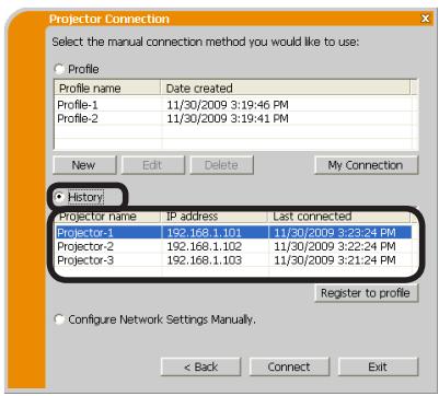
text_image
Projector Connection Select the manual connection method you would like to use: Profile Profile name Date created Profile-1 11/30/2009 3:19:46 PM Profile-2 11/30/2009 3:19:41 PM New Edit Delete My Connection History Projector name IP address Last connected Projector-1 192.168.1.101 11/30/2009 3:23:24 PM Projector-2 192.168.1.102 11/30/2009 3:22:24 PM Projector-3 192.168.1.103 11/30/2009 3:21:24 PM Register to profile Configure Network Settings Manually. < Back Connect ExitIf you want to copy a history record to a profile data, select one of the history record and click the [Register to profile]. The profile data cannot be erased automatically.
NOTE • The number of the history record is maximum 10 for each network adapter. When the 11th data is stored, the oldest record among the 10 will be overwritten.
- The date & time information in each history record is renewed when the network is connected by using the history record.
- If the DHCP is set on in the projector, the network connection between the projector and computer may not be established since IP address may be varied.
- Even if you use the profile connection, it will be memorized as a history record.
1.7 Configuring the network settings manually
All setting for the network connection between the projector and computer is input manually.
Select the [Configure Network Settings Manually].
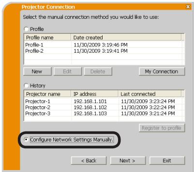
text_image
Projector Connection Select the manual connection method you would like to use: Profile Profile name Date created Profile-1 11/30/2009 3:19:46 PM Profile-2 11/30/2009 3:19:41 PM New Edit Delete My Connection History Projector name IP address Last connected Projector-1 192.168.1.101 11/30/2009 3:23:24 PM Projector-2 192.168.1.102 11/30/2009 3:22:24 PM Projector-3 192.168.1.103 11/30/2009 3:21:24 PM Register to profile Configure Network Settings Manually. < Back Next > ExitThe information to be input manually is different, depending on how you want to connect the projector and computer.
Wireless LAN
The projector is required to be connected to an access point by a LAN cable.
Wired LAN
If you use the wired LAN, go to Wired LAN.
1.7 Configuring the network settings manually (continued)
Wireless LAN
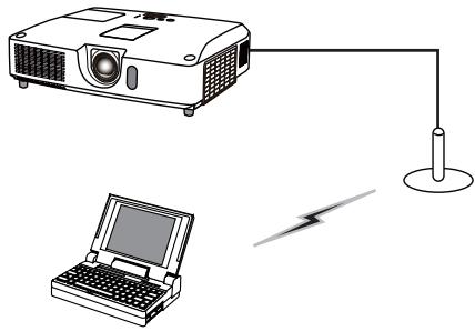
natural_image
Diagram showing a projector connected to a laptop and a power cord (no text or symbols)1) The setting on the access point. *1 Enter the following information.
SSID: WirelessAccessPoint (example)
Encryption: WEP64bit (example)
Encryption key *2: ********** (example)
Mode: INFRASTRUCTURE
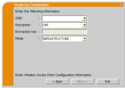
text_image
Projector Connection Enter the following information. SSID : Encryption : OFF Encryption key : Mode : INFRASTRUCTURE Enter Wireless Access Point Configuration Information. < Back Next > Exit2) Click the [Next].
3) Enter the following information that is set in the projector. *3
IP address : 192.168.1.10 (example)
Subnet mask: 255.255.255.0 (example)
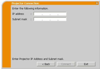
text_image
Projector Connection Enter the following information. IP address : . . . . Subnet mask : . . . . Enter Projector IP Address and Subnet mask: < Back Connect Exit4) Click the [Connect].
5) The wireless connection will be established.
Proceed to item 1.8 Confirming the connection to your destination.
*1 Contact the network administrator to find out the setting on the access point.
*2 If you use an encryption, you need to set it. Contact the network administrator to check the encryption key that is set in the projector.
The encryption key is always shown as “**********”.
*3 To find the network setting on the projector, refer to the NOTE.
1.7 Configuring the network settings manually (continued)
Wired LAN
1) Enter the following information for the projector. *1
IP address : 192.168.1.10 (example)
Subnet mask : 255.255.255.0 (example)
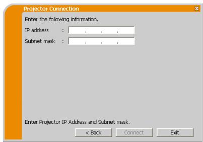
text_image
Projector Connection Enter the following information. IP address : . . . . Subnet mask : . . . . Enter Projector IP Address and Subnet mask: < Back Connect Exit2) Click the [Connect].
3) The network connection will be established.
Proceed to item 1.8 Confirming the connection to your destination.
*1 To find the network setting on the projector, refer to the NOTE.
[Troubleshooting]
■ A network connection could not be established.
Windows prevented network configuration changes.
You may log in the Windows under User authority.
Click the [OK], then the "LiveViewer" main menu is displayed even though the network is not established. Click 📄 on the main menu and go back to item 1.5 Selecting the network connection method.
![VIEWSONIC PRO9500 - [Troubleshooting] - 1](/content/2025/01/170018/images/928768b49303bc6d0adb6b99d88b15d5c0b22599b951d6073cd6e29c31643d93.jpg)
text_image
Projector Connection A network connection could not be established. Windows prevented network configuration changes. Please insure that you are authorized to make these changes or check your security settings.Consult to the network administrator. Log in the Windows under Administrator authority. After that, please resume at item 1.3.2 Starting the “LiveViewer”.
1.7 Configuring the network settings manually (continued)
■ If you need to add a Network configuration on your computer to connect to the projector.
This dialog will be displayed when you need to add a Network configuration on your computer to connect to the projector. Confirm with your network administrator if the Network configuration displayed on the dialog is OK, and then click the [Yes].
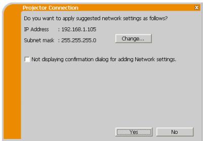
text_image
Projector Connection Do you want to apply suggested network settings as follows? IP Address : 192.168.1.105 Subnet mask : 255.255.255.0 Change... Not displaying confirmation dialog for adding Network settings. Yes NoClick the [NO], then the "LiveViewer" main menu is displayed even though the network is not established. Click 📄 on the main menu and go back to item 1.5 Selecting the network connection method.
If you put a check mark in the box "Not displaying confirmation dialog for adding Network settings", the projector memorizes current configuration and this dialog is not displayed again. To display this dialog again, click Option 🔒 icon in the "LiveViewer" main menu and remove the check mark in the box "Not displaying confirmation dialog for adding Network settings".
If you want to change the Network configuration to add, click the [Change]. A dialog for changing the Network configuration as shown to the right will be displayed. Enter IP address and subnet mask, then click the [OK]. Procedure to connect to the projector will start.
Proceed to item 1.8 Confirming the connection to your destination.
If you click the [Cancel], you will return to the dialog for adding a Network configuration.
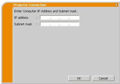
text_image
Projector Connection Enter Computer IP Address and Subnet mask. IP address : . . . . Subnet mask : . . . . OK Cancel1.7 Configuring the network settings manually (continued)
If the entered IP address and projector's IP address are the same, a warning dialog shown to the right will be displayed.
Click the [OK], and then enter a different IP address from the projector's one in the dialog for changing Network configuration.
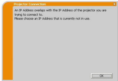
text_image
Projector Connection An IP Address overlaps with the IP Address of the projector you are trying to connect to. Please choose an IP Address that is currently not in use.If the connection is not available with the entered Network configuration, a warning dialog shown to the right will be displayed. Click the [OK] to return to the dialog for changing the Network configuration, and then enter appropriate configuration.
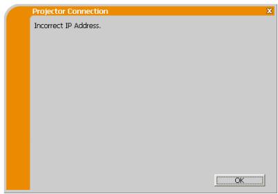
text_image
Projector Connection Incorrect IP Address. OKNOTE • If a Network configuration to connect to the projector has been added on the computer, the added Network configuration will be erased once the application software is closed.
■ Are you sure you want to connect the selected projector?
The message is appeared when the wireless adapter you selected is already used for another network connection.
- To connect, click the [Yes]. Proceed to item 1.8 Confirming the connection to your destination.
- Not to connect, click the [No] then the "LiveViewer" main menu is displayed even though the network is not established. Click 📄 on the main menu to go back to item 1.5 Selecting the network connection method.
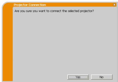
text_image
Projector Connection Are you sure you want to connect the selected projector? Yes No1.8 Confirming the connection to your destination
1.8.1 Connection and transmission
When the network connection is established, the “Connection to Projector successful” screen is displayed.
Make sure that the right projector that you want to send your image to is selected, by checking the projector name and IP address shown in the screen.
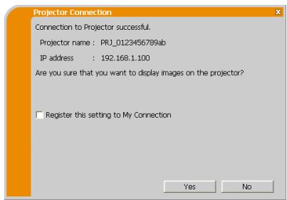
text_image
Projector Connection Connection to Projector successful. Projector name : PRJ_0123456789ab IP address : 192.168.1.100 Are you sure that you want to display images on the projector? □ Register this setting to My Connection Yes No- To send images to the projector, click the [Yes]. The transmission will be started. To display the transmitted images, select the LAN port as input source on the projector.
- Not to send, click the [No], then the “LiveViewer” main menu is displayed in stand-by mode. (Stand-by mode is the state where there is no image transmission, although the network connection is established.)
The transmission can be started, if you click ▶ or □ button on the "LiveViewer" main menu.
If you wish to use the current connection setting as a profile data for My Connection, check in the box for the [Register this setting to My Connection].
[Troubleshooting]
■ This projector is currently in use (Presenting) by another user.
The projector you want to send your images to is occupied by another computer in the Presenter mode.
Click the [OK], then the "LiveViewer" main menu is displayed in stand-by mode. Retry to send your images, after the Presenter mode is off.
![VIEWSONIC PRO9500 - [Troubleshooting] - 1](/content/2025/01/170018/images/8b9cbc270e93aca3c393239acfbcc3caa2fd22190b8e0620418bbcbac926af29.jpg)
text_image
Projector Connection This projector is currently in use (Presenting) by another user. You cannot connect with this projector until the other session (Presenter Mode) is finished.1.8 Confirming the connection to your destination (continued)
■ A Slideshow is currently running on the projector that you are trying to display to.
The projector you want to send your images to is in the Slideshow mode in the PC-LESS Presentation.
- Click the [Yes], then the projector will stop the Slideshow and switch the input source to the LAN port.
- Click the [No], then the projector is remained in the Slideshow mode, and the "LiveViewer" main menu is displayed in stand-by mode on your computer.
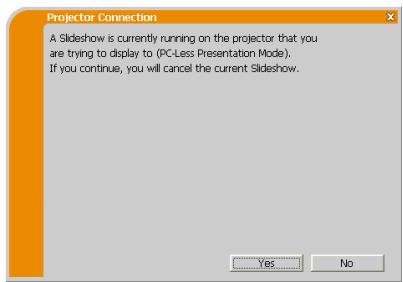
text_image
Projector Connection A Slideshow is currently running on the projector that you are trying to display to (PC-Less Presentation Mode). If you continue, you will cancel the current Slideshow. Yes No■ Are you sure you want to change the input channel of the Projector to LAN?
The projector is not set to the LAN as an input signal.
- Click the [Yes], then the projector is switched to the LAN.
- Click the [No], then the projector is remained as it is, and the “LiveViewer” main menu is displayed in stand-by mode on your computer.
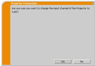
text_image
Projector Connection Are you sure you want to change the input channel of the Projector to "LAN?" Yes No1. Connection to the network
1.8 Confirming the connection to your destination (continued)
1.8.2 Connection error
When the connection to the projector could not be established, an error message, “Network Connection not established”, will come up.
Click the [OK] then the “LiveViewer” main menu is displayed even though the network is not established. Click 📄 on the main menu to go back to item 1.5 Selecting the network connection method.
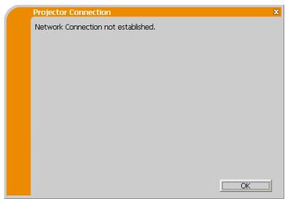
text_image
Projector Connection Network Connection not established. OKNOTE • Check the network setting in the projector, and retry the connection from item 1.3.2 Starting the “LiveViewer”.
1.9 Profile data
1.9.1 Outline of Profile data
The network setting to connect the projector and computer can be stored as a profile data. Once the data is stored, all you need to do is to select the data to connect to the network. It is recommended when the same network connection is often used.
1.9.2 Making Profile data
The profile data is made on the Manual Configuration screen.
Up to 10 profile data can be stored for each network adapter.
1) Select the [Profile] and click the [New].
2) The “Create new profile” will come up. If you have already made 10 profile data, you cannot make a new one, until you delete a stored data.
Input all information required for your network connection.
If you want to clear the information you input, click the [Clear].
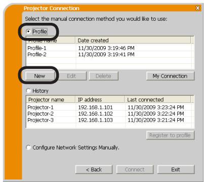
text_image
Projector Connection Select the manual connection method you would like to use: Profile Profile Name Date created Profile-1 11/30/2009 3:19:46 PM Profile-2 11/30/2009 3:19:41 PM New Edit Delete My Connection History Projector name IP address Last connected Projector-1 192.168.1.101 11/30/2009 3:23:24 PM Projector-2 192.168.1.102 11/30/2009 3:22:24 PM Projector-3 192.168.1.103 11/30/2009 3:21:24 PM Register to profile Configure Network Settings Manually. < Back Connect Exit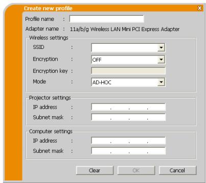
text_image
Create new profile Profile name : Adapter name : 11a/b/g Wireless LAN Mini PCI Express Adapter Wireless settings SSID : Encryption : OFF Encryption key : Mode : AD-HOC Projector settings IP address : . . . Subnet mask : . . . Computer settings IP address : . . . Subnet mask : . . . Clear OK Cancel3) Click the [OK], after all information is set. If you don't want to store it, click the [Cancel].
4) The new profile data is shown in the profile list, if you click the [OK].
NOTE • When you make a new profile data, it is strongly recommended to check that the new data can work properly by selecting the data at the Profile connection.
- If you change a network adapter on your computer, make a new profile data for the adapter.
1.9 Profile data (continued)
1.9.3 Editing Profile data
If necessary, the profile data can be edited on the Manual Configuration screen.
1) Select the [Profile], and select one of the data listed in the window.
2) Click the [Edit].
3) The "Edit profile" screen will come up.
4) Edit the information required to be revised. If you want to clear all information in the window, click the [Clear].
5) Click the [OK], after the editing is completed. If you don't want to store it, click the [Cancel].
6) The edited profile data is stored and shown in the profile list with the new date created information, if you click the [OK].
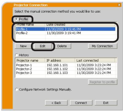
text_image
Projector Connection Select the manual connection method you would like to use: Profile Profile name Date created Profile-1 11/30/2009 3:19:46 PM Profile-2 11/30/2009 3:19:41 PM New Edit Delete My Connection History Projector name IP address Last connected Projector-1 192.168.1.101 11/30/2009 3:23:24 PM Projector-2 192.168.1.102 11/30/2009 3:22:24 PM Projector-3 192.168.1.103 11/30/2009 3:21:24 PM Register to profile Configure Network Settings Manually. < Back Connect Exit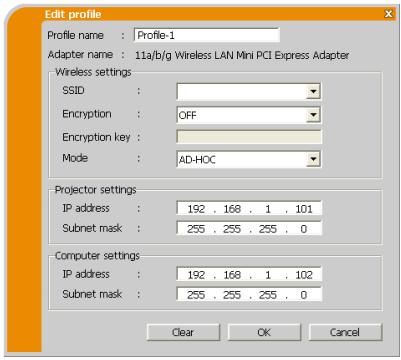
text_image
Edit profile Profile name : Profile-1 Adapter name : 11a/b/g Wireless LAN Mini PCI Express Adapter Wireless settings SSID : Encryption : OFF Encryption key : Mode : AD-HOC Projector settings IP address : 192 . 168 . 1 . 101 Subnet mask : 255 . 255 . 255 . 0 Computer settings IP address : 192 . 168 . 1 . 102 Subnet mask : 255 . 255 . 255 . 0 Clear OK CancelNOTE • When you edit a profile data, it is strongly recommended to check that the edited data can work properly by selecting the data at the Profile connection.
1.9 Profile data (continued)
1.9.4 Registering My Connection
One of the profile data, which is often used, can be registered as the My Connection profile data. Once the data is registered, all you need to do is to select the My Connection to connect to the network.
1) Click the [My Connection].
2) The "Add My Connection" screen will come up.
The currently selected profile data for the My Connection is shown with a check mark in the list.
3) Select one of the profile data listed in the window and put a mark in the check box. The data selected before is turned unmarked.
4) Click the [OK], then the window is closed. If you don't want to select a new one, click the [Cancel].
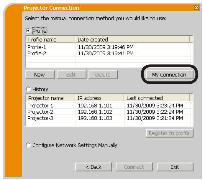
text_image
Projector Connection Select the manual connection method you would like to use: Profile Profile name Date created Profile-1 11/30/2009 3:19:46 PM Profile-2 11/30/2009 3:19:41 PM New Edit Delete My Connection History Projector name IP address Last connected Projector-1 192.168.1.101 11/30/2009 3:23:24 PM Projector-2 192.168.1.102 11/30/2009 3:22:24 PM Projector-3 192.168.1.103 11/30/2009 3:21:24 PM Register to profile Configure Network Settings Manually. < Back Connect Exit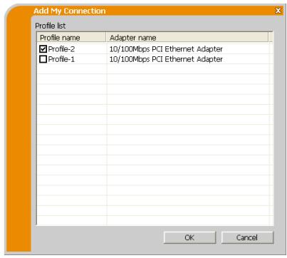
text_image
Add My Connection Profile list Profile name Adapter name ✓ Profile-2 10/100Mbps PCI Ethernet Adapter ✓ Profile-1 10/100Mbps PCI Ethernet Adapter OK CancelNOTE • If you don't want to use the My Connection, mark no data listed in the window, and click the [OK].
- In the list, all profile data are shown no matter which network adapter is selected. You can register a profile data that is not for currently selected network adapter as the My Connection profile data.
1.9 Profile data (continued)
Also, you can register a profile data to My Connection, when the network connection is established. When it is established, the “Connection to Projector successful” screen is displayed.
If you wish to use the current connection setting for My Connection, check in the box for the [Register this setting to My Connection]. And then, if it is okay to overwrite the present data for My Connection, click the [OK]. A new profile data will be created and it is registered as My Connection profile data.
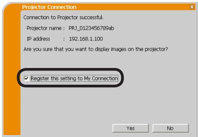
text_image
Projector Connection Connection to Projector successful. Projector name : PRJ_0123456789ab IP address : 192.168.1.100 Are you sure that you want to display images on the projector? ✓ Register this setting to My Connection Yes NoNOTE • If there are already 10 profile data, the check box cannot be checked. Please erase one of the existing profile data.
- The profile name for the stored data is assigned by the “LiveViewer” automatically. The name will be shown at the right side of the check box.
2. Network Presentation
2.1 Using the "LiveViewer"
When you get the connection between your projector and computer, the "LiveViewer" main menu will be shown on the computer screen.
On the main menu you can configure settings and operate functions to send your images to the projector.
2.1.1 Main menu and Operating buttons
1) Menu Type
There are 2 type of the main menu, Easy type and Advanced type, which can be switched on screen.
- When the network connection is not established, the Advanced type will be on screen.
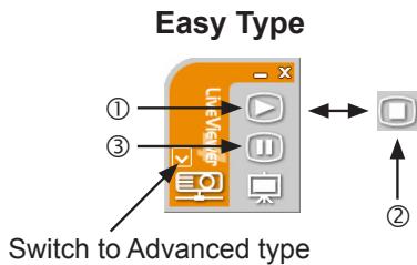
text_image
Easy Type ① ③ Switch to Advanced type LiveView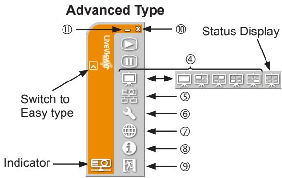
text_image
Advanced Type Switch to Easy type Indicator Status Display2) Operating buttons
① Starting Capture button
The transmission to the projector is started and the images will be displayed.
The Display mode will be the Single PC mode at first.
② Stop button
The image transmission is stopped.
NOTE • The images may not be displayed on screen, if the Start/Stop buttons are clicked repeatedly.
- The primary image is displayed in multi-display environment.
2.1 Using the "LiveViewer" (continued)
③ Hold button
The image on screen is temporally frozen.
The last image before the button is clicked is remained on screen.
You can revise the image data on your computer without showing it on the projector's screen.
④ Display mode button
The button switches the Single PC mode and Multi PC mode.
⑤ Connect button
The screen to select the connection mode is displayed.
Go to item 1.5.
⑥ Option button
The option screen is displayed.
⑦ Web control button
Starts the Web browser on your computer and displays Web control screen to control the projector and change various settings for the projector.
⑧ Information button
The version of the “LiveViewer” is displayed.
⑨, ⑩ Close button
The network is disconnected and the "LiveViewer" is closed.
⑪ Minimize button
The displayed icon changes as shown below depending on the status of the "LiveViewer". If the icon is double-clicked, the last type of the main menu will be shown on screen.
Connected

Disconnected

Not connected

Hold

2.1 Using the "LiveViewer" (continued)
2.1.2 Displaying the status
1) Indicator
The indicator shows the following status.
| Indicator | Status | Note |
 | Not connected | The network connection to the projector is not established yet. |
 | Hold | The network connection is established, but the image transmissions on hold. |
 | Connected | The network connection is established and the images on the computer are being sent to the projector. |
 | Disconnected | The network connection to the projector is disconnected. |
2) Status Display in Multi PC mode
The icon is displayed at the right end of the Display mode buttons.
One of the following icons to inform which quarter screens are used will be shown.
| Status | Status icon |
| No computer is on screen |  |
| One computer is on screen. |  |
| Two computers are on screen. |  |
| Three computers are on screen. |  |
| Four computers are on screen. |  |
NOTE • The status display is refreshed in every 3 seconds.
- If the status cannot be acquired, it will not be refreshed.
2.1 Using the "LiveViewer" (continued)
2.1.3 Switching the display mode
The “LiveViewer” has the Single PC mode and Multi PC mode. The modes can be switched on the main menu.
1) Click the 📄 button on the main menu.
The buttons below are displayed.
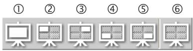
text_image
① ② ③ ④ ⑤ ⑥⑥:Status Display
2) Select from ① to ⑤ buttons, and click it.
① Switching to the Single PC mode : Your image is displayed on full screen.
②-⑤ Switching to the Multi PC mode : Your image is displayed on a quarter screen identified in the button.
3) The projector screen is switched to the mode selected above, and the transmission of your computer image will be started to display your image on the screen.
4) The icon ☐ on the main menu is replaced by the icon you selected.
NOTE • The image transmission will be stopped, when you click the Single mode button while the projector is in the Single PC mode or you click one of the Multi mode buttons that shows the quarter screen which is currently displaying your computer images in the Multi PC mode.
- If the Multi PC mode is selected, the projector screen is automatically divided to 4 zones.
- When the Presenter mode is enabled and the projector is used by a computer in the Single PC mode, images from other computers cannot be sent to the projector even if the 📄 (Full screen) button is pressed.
- When a quarter-screen occupied by another computer is selected, image transmission from that computer will be put on hold and the image of the currently specified computer will be displayed.
The display mode can be set also by using the MULTI PC MODE in the PRESENTATION item in the NETWORK menu. The last setting made will take effect regardless of the setting method.
2.1 Using the "LiveViewer" (continued)
2.1.4 Option menu
Clicking the Option button displays the option menu on screen.
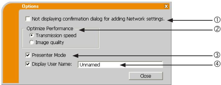
text_image
Options Not displaying confirmation dialog for adding Network settings. Optimize Performance Transmission speed Image quality Presenter Mode Display User Name: Unnamed Close① “Not displaying confirmation dialog for adding Network settings”
This setting allows you to choose to display or not the confirmation dialog for adding a Network configuration when you connect your computer to the projector. It is turned off by default.
② Optimize Performance
The “LiveViewer” captures computer screen in JPEG data and sends the JPEG data to the projector. The “LiveViewer” has two options that have different compression rate of JPEG data.
Transmission speed
Speed takes priority over Image quality.
It makes JPEG compression rate higher.
The screen on the projector is rewritten quicker because the transferred data is smaller, but the image quality is worse.
Image quality
Image quality takes priority over Speed.
It makes JPEG compression rate lower.
The screen on the projector is rewritten slower because the transferred data is larger, but the image quality is better.
2.1 Using the "LiveViewer" (continued)
③ Presenter Mode
In the Single PC mode, the projector can be occupied by one computer and can block an access from any other computer, if the Presenter mode is selected in the “LiveViewer”.
While making your presentation, you don't need to worry that the image on screen is unexpectedly switched to an image sent by another computer.
If you want to turn it on, put a check mark in the check box.
NOTE • If the Multi PC mode is selected, the setting for the Presenter mode is invalid.
- When switching from the Multi PC mode to the Single PC mode, the Presenter mode setting of the computer is valid.
- The Presenter Mode is set valid in factory default setting.
- In addition to using the software menu on the computer on which Presenter Mode is turned on, you can cancel this function by using the projector's OSD menu QUIT PRESENTER MODE EXECUTE of the PRESENTATION item in the NETWORK menu.
④ Display User Name
A “User Name” that is up to 20 letters can be input by using alphanumeric characters.
The user name can be displayed on the projector screen, so you can find out whose image is currently on the screen.
(Refer to NETWORK menu in the Operating Guide)
If the check box is not marked, the information is not sent to the projector.
2.2 Starting the Network Presentation
This chapter explains the Network Presentation feature with which you can project computer images transmitted through a network.
The “LiveViewer” allows you to project images from one or multiple computers by connecting the projector to an existing network without using computer cables.
This Network Presentation feature helps you to smoothly make your presentations and conduct conferences.
To start the Network Presentation, select the LAN port as the input source on the projector and click the Starting Capture button on the “LiveViewer”.
2.2.1 Display mode
Two display modes, Single PC mode and Multi PC mode, are available for the Network Presentation.
1) Single PC mode
The projector displays images sent by one computer.
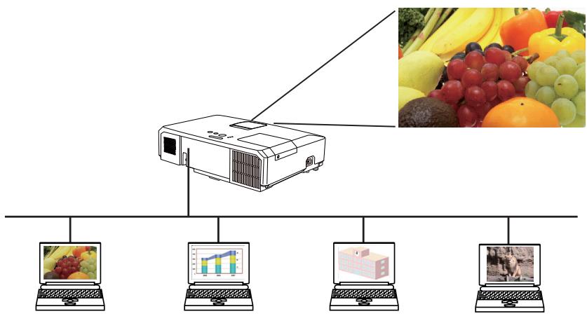
flowchart
graph TD
    A[" projector"] --> B[" Laptop 1"]
    A --> C[" Laptop 2"]
    A --> D[" Laptop 3"]
    A --> E[" Laptop 4"]
    A --> F[" Laptop 5"]
    A --> G[" Laptop 6"]
    H[" Fruit Image"] --> A
    I[" Fruit Image"] --> A
    J[" Fruit Image"] --> A
    K[" Fruit Image"] --> A
    L[" Fruit Image"] --> A
    M[" Fruit Image"] --> A
    N[" Fruit Image"] --> A
    O[" Fruit Image"] --> A
    P[" Fruit Image"] --> A
    Q[" Fruit Image"] --> A
    R[" Fruit Image"] --> A
2.2 Starting the Network Presentation (continued)
2) Multi PC mode
The projector screen is divided to 4 zones. The projector displays images in one zone sent by a computer, so that the projector can display images sent by up to 4 computers at the same time.
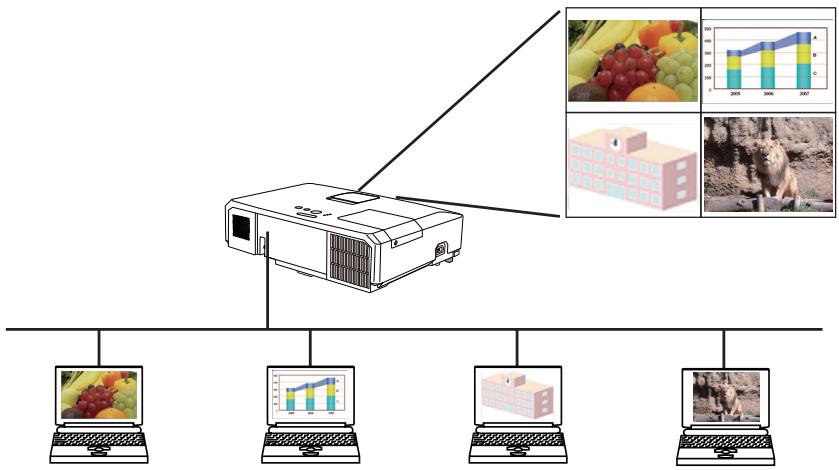
flowchart
graph TD
    A[" projector"] --> B[" Laptop 1"]
    A --> C[" Laptop 2"]
    A --> D[" Laptop 3"]
    A --> E[" Laptop 4"]
    A --> F[" Laptop 5"]
    A --> G[" Laptop 6"]
    A --> H[" Laptop 7"]
    A --> I[" Laptop 8"]
    A --> J[" Laptop 9"]
    A --> K[" Laptop 10"]
    A --> L[" Laptop 11"]
    A --> M[" Laptop 12"]
    A --> N[" Laptop 13"]
    A --> O[" Laptop 14"]
    A --> P[" Laptop 15"]
    A --> Q[" Laptop 16"]
    A --> R[" Laptop 17"]
    A --> S[" Laptop 18"]
    A --> T[" Laptop 19"]
    A --> U[" Laptop 20"]
    A --> V[" Laptop 21"]
    A --> W[" Laptop 22"]
    A --> X[" Laptop 23"]
    A --> Y[" Laptop 24"]
    A --> Z[" Laptop 25"]
    A --> AA[" Laptop 26"]
    A --> AB[" Laptop 27"]
    A --> AC[" Laptop 28"]
    A --> AD[" Laptop 29"]
    A --> AE[" Laptop 30"]
    A --> AF[" Laptop 31"]
    A --> AG[" Laptop 32"]
    A --> AH[" Laptop 33"]
    A --> AI[" Laptop 34"]
    A --> AJ[" Laptop 35"]
    A --> AK[" Laptop 36"]
    A --> AL[" Laptop 37"]
    A --> AM[" Laptop 38"]
    A --> AN[" Laptop 39"]
    A --> AO[" Laptop 40"]
    A --> AP[" Laptop 41"]
    A --> AQ[" Laptop 42"]
    A --> AR[" Laptop 43"]
    A --> AS[" Laptop 44"]
    A --> AT[" Laptop 45"]
    A --> AU[" Laptop 46"]
    A --> AV[" Laptop 47"]
    A --> AW[" Laptop 48"]
    A --> AX[" Laptop 49"]
    A --> AY[" Laptop 50"]
    A --> AZ[" Laptop 51"]
    A --> BA[" Laptop 52"]
    A --> BB[" Laptop 53"]
    A --> BC[" Laptop 54"]
    A --> BD[" Laptop 55"]
    A --> BE[" Laptop 56"]
    A --> BF[" Laptop 57"]
    A --> BG[" Laptop 58"]
    A --> BH[" Laptop 59"]
    A --> BI[" Laptop 60"]
    A --> BJ[" Laptop 61"]
    A --> BK[" Laptop 62"]
    A --> BL[" Laptop 63"]
    A --> BM[" Laptop 64"]
    A --> BN[" Laptop 65"]
    A --> BO[" Laptop 66"]
    A --> BP[" Laptop 67"]
    A --> BQ[" Laptop 68"]
    A --> BR[" Laptop 69"]
    A --> BS[" Laptop 70"]
    A --> BT[" Laptop 71"]
    A --> BU[" Laptop 72"]
    A --> BV[" Laptop 73"]
    A --> BW[" Laptop 74"]
    A --> BX[" Laptop 75"]
    A --> BY[" Laptop 76"]
    A --> BZ[" Laptop 77"]
    A --> CA[" Laptop 78"]
    A --> CB[" Laptop 79"]
    A --> CC[" Laptop 80"]
    A --> CY[" Laptop 81"]
    A --> CZ[" Laptop 82"]
    A --> DA[" Laptop 83"]
    A --> DB[" Laptop 84"]
    A --> DC[" Laptop 85"]
    A --> DD[" Laptop 86"]
    A --> DE[" Laptop 87"]
    A --> DF[" Laptop 88"]
    A --> DG[" Laptop 89"]
    A --> DH[" Laptop 90"]
    A --> DI[" Laptop 91"]
    A --> DJ[" Laptop 92"]
    A --> DK[" Laptop 93"]
    A --> DL[" Laptop 94"]
    A --> DV[" Laptop 95"]
    A --> DW[" Laptop 96"]
    A --> DX[" Laptop 97"]
    A --> DY[" Laptop 98"]
    A --> DYD[" Laptop 99"]
2.2.2 Presenter mode
In the Single PC mode, the projector can be occupied by one computer and can block an access from any other computer, if the Presenter mode is selected in the "LiveViewer".
While making your presentation, you don't need to worry that the image on screen is unexpectedly switched to an image sent by another computer.
The Presenter mode can be set on the Option menu in the “LiveViewer” main menu.
2.2.3 Display User Name
A “User Name” can be input in the “LiveViewer”, which is displayed on screen by operating the menu on the projector. So, it can be found out whose image is currently displayed on screen.
3. Web Control
You can adjust or control the projector via a network from a web browser on a computer that is connected to the same network.
NOTE • Internet Explorer 6.0 or later is required.
- If JavaScript is disabled in your web browser configuration, you must enable JavaScript in order to use the projector web pages properly. See the Help files for your web browser for details on how to enable JavaScript.
- It is recommended that all web browser updates are installed.
3.1 Logon
To use the Web Control function, you need to logon with your user name and password.
Refer to the following for configuring or controlling the projector via a web browser.
Example: If the IP address of the projector is set to 192.168.1.10:
1) Display the logon window as shown on the right. There are two options to display this window.
① Using the "LiveViewer"
Connect your computer and the projector via Network using the "LiveViewer".
Then click the Web Control button 📋 on the "LiveViewer" main menu to start the Web browser software.
② Using Web browser software
Make sure that your computer and the projector is connected via network, and then start Web browser.
Enter the projector's IP address into URL
input box of the Web browser as the example below, and then press the Enter key or ➤ button.
Example: If the IP address of the projector is set to 192.168.1.10:
Enter "http://192.168.1.10/" into the address bar of the web browser and press the Enter key or click → button.
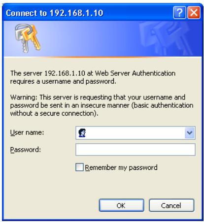
text_image
Connect to 192.168.1.10 The server 192.168.1.10 at Web Server Authentication requires a username and password. Warning: This server is requesting that your username and password be sent in an insecure manner (basic authentication without a secure connection). User name: Password: Remember my password OK Cancel2) Enter your user name and password, and then click the [OK].
NOTE • The language used on the Web Control screen is the same as that of the OSD on the projector. If you want to change it, you need to change the OSD language on the projector. (SCREEN menu in the Operating Guide)
3.1 Logon (Continued)
Below are the factory default settings for user name and password.
| User name | Password |
| Administrator |
If you logon successfully, the screen below will be displayed.
Main menu
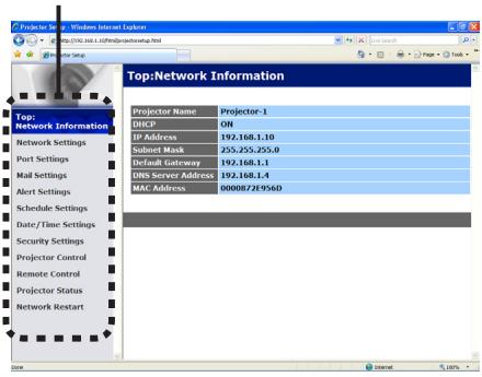
text_image
Top:Network Information Projector Name Projector-1 DHCP ON IP Address 192.168.1.10 Subset Mask 255.255.255.0 Default Gateway 192.168.1.1 DNS Server Address 192.168.1.4 MAC Address 00008728956D3) Click the desired operation or configuration item on the main menu.
3.2 Network Information
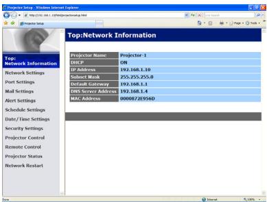
text_image
Projector Setup - Windows Internet Explorer http://102.168.1.13@projectorsetup.html Top:Network Information Projector Name Projector 1 DHCP ON IP Address 192.168.1.10 Subject Mark 255-255-255.0 Default Gateway 192.168.1.1 DNS Server Address 192.168.1.4 MAC Address 0000872E954D Projector Control Remote Control Projector Status Network ResetartDisplays the projector's current network configuration settings.
| Item | Description |
| Projector Name | Displays the projector name settings. |
| DHCP | Displays the DHCP configuration settings. |
| IP Address | Displays the current IP address. |
| Subnet Mask | Displays the subnet mask. |
| Default Gateway | Displays the default gateway. |
| DNS Server Address | Displays the DNS server address. |
| MAC Address | Displays the ethernet MAC address. |
3.3 Network Settings
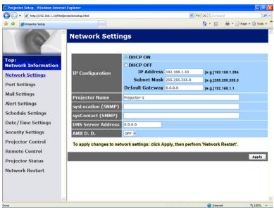
text_image
Network Settings Top: Network Information Network Settings Port Settings Mail Settings Alert Settings Schedule Settings Date/ Time Settings Security Settings Projector Control Remote Control Projector Status Network Restart Network ON DHCP OFF IP Address: 192.388.1.10 Subnet Mask: 155.255.255.0 Default Gateway: 4.6.0 Projector Name Projector-1 sysd occlusion (SDMP) sysdContact (SDMP) DNS Server Address: 0.6.0.0 AMR D.D. 272.0 To apply changes to network settings: click Apply, then perform 'Network Restart'. ApplyDisplays and configures network settings.
| Item | Description | |
| IP Configuration | Configures network settings. | |
| DHCP ON | Enables DHCP. | |
| DHCP OFF | Disables DHCP. | |
| IP Address | Configures the IP address when DHCP is disabled. | |
| Subnet Mask | Configures the subnet mask when DHCP is disabled. | |
| Default Gateway | Configures the default gateway when DHCP is disabled. | |
| Projector Name | Configures the name of the projector.The length of the Projector Name can be up to 64 alphanumeric characters. Only alphabets, numbers and following symbols can be used. !"#$%&'*+,-./:;<=>?@[^_^_{}~ and space.Particular projector name is pre-assigned by default. | |
| sysLocation (SNMP) | Configures the location to be referred to when using SNMP.The length of the sysLocation can be up to 255 alphanumeric characters. Only numbers ‘0-9’ and alphabet ‘a-z’, ‘A-Z’ can be used. | |
| sysContact (SNMP) | Configures the contact information to be referred to when using SNMP.The length of the sysContact can be up to 255 alphanumeric characters. Only numbers ‘0-9’ and alphabet ‘a-z’, ‘A-Z’ can be used. | |
| DNS Server Address | Configures the DNS server address. | |
| AMX D.D.(AMX Device Discovery) | Configures the AMX Device Discovery setting to detect the projector from the controllers of AMX connected to the same network. For the details of AMX Device Discovery, visit the AMX web site.URL: http://www.amx.com | |
Click the [Apply] button to save the settings.
NOTE • The new configuration settings are activated after restarting the network connection. When the configuration settings are changed, you must restart the network connection. You can restart the network connection by clicking the [Network Restart] on the main menu. • If you connect the projector to an existing network, consult a network administrator before setting server addresses.
3.4 Port Settings
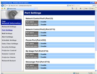
text_image
Projector Setup - Windows Internet Explorer Port Settings Network Control Port1 (Port:23) Port open Enable Authentication Enable Network Control Port2 (Port:9715) Port open Enable Authentication Enable P.J.Link Port (Port:4352) Port open Enable Authentication Enable My Image Port (Port:9716) Port open Enable Authentication Enable Messenger Port (Port:9710) Port open Enable Authentication EnableDisplays and configures communication port settings.
| Item | Description | |
| Network Control Port1 (Port:23) | Configures command control port 1 (Port:23). | |
| Port open | Click the [Enable] check box to use port 23. | |
| Authentication | Click the [Enable] check box when authentication is required for this port. | |
| Network Control Port2 (Port:9715) | Configures command control port 2 (Port:9715). | |
| Port open | Click the [Enable] check box to use port 9715. | |
| Authentication | Click the [Enable] check box when authentication is required for this port. | |
| PJLinkTM Port (Port:4352) | Configures the PJLinkTM port (Port:4352). | |
| Port open | Click the [Enable] check box to use port 4352. | |
| Authentication | Click the [Enable] check box when authentication is required for this port. | |
| My Image Port (Port:9716) | Configures the My Image Port (Port:9716). | |
| Port open | Click the [Enable] check box to use port 9716. | |
| Authentication | Click the [Enable] check box when authentication is required for this port. | |
| Messenger Port (Port:9719) | Configures the Messenger Port (Port:9719). | |
| Port open | Click the [Enable] check box to use port 9719. | |
| Authentication | Click the [Enable] check box when authentication is required for this port. | |
| SNMP Port | Configures the SNMP port. | |
| Port open | Click the [Enable] check box to use SNMP. | |
| Trap address | Configures the destination of the SNMP Trap in IP format.• The address allows not only IP address but also domain name if the valid DNS server is setup in the Network Settings. The maximum length of host or domain name is up to 255 characters. | |
| Download MIB file | Downloads a MIB file from the projector. | |
| Network Bridge Port | Configures the Bridge port number. | |
| Port Number | Input the port number.Except for 9715, 9716, 9719, 9720, 5900, 5500, 4352 between 1024 and 65535 can be set up. It is set to 9717 as the default setting. | |
Click the [Apply] button to save the settings.
NOTE • The new configuration settings are activated after restarting the network connection. When the configuration settings are changed, you must restart the network connection. You can restart the network connection by clicking the [Network Restart] on the main menu.
3.5 Mail Settings
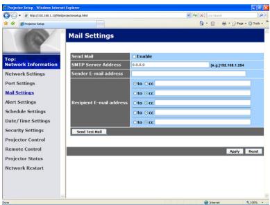
text_image
Projector Setup - Windows Internet Explorer http://102.108.1.139@mailsetlab.html Projector Setup Mail Settings Send Mail Enable SMTP Server Address 0-0-0 #g:1998.588.184 Sender E-mail address to :cc to :cc Recipient E-mail address to :cc to :cc Send Text Mail Apply Reset Top: Network Information Port Settings Mail Settings Alert Settings Schedule Settings Date/Time Settings Security Settings Projector Control Remote Control Projector Status Network RestartDisplays and configures e-mail addressing settings.
| Item | Description |
| Send Mail | Click the [Enable] check box to use the e-mail function.Configure the conditions for sending e-mail under the Alert Settings. |
| SMTP Server Address | Configures the address of the mail server in IP format.• The address allows not only IP address but also domain name if the valid DNS server is setup in the Network Settings. The maximum length of host or domain name is up to 255 characters. |
| Sender E-mail address | Configures the sender e-mail address.The length of the sender e-mail address can be up to 255 alphanumeric characters. |
| Recipient E-mail address | Configures the e-mail address of up to five recipients. You can also specify the [TO] or [CC] for each address. The length of the recipient e-mail address can be up to 255 alphanumeric characters. |
Click the [Apply] button to save the settings.
NOTE • You can confirm whether the mail settings work correctly using the [Send Test Mail] button. Please enable Send mail setting before clicking the [Send Test Mail].
- If you connect the projector to an existing network, consult a network administrator before setting server addresses.
3.6 Alert Settings
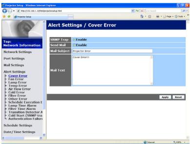
text_image
Projector Setup - Windows Internet Explorer http://10.108.1.139@snmp.org/nashv3.html Alert Settings / Cover Error Top: Network Information Network Settings Port Settings Mail Settings Alert Settings + Cover Error - I am Error - Lamp Error - Temp Error - Air Flow Error - Cold Error - Filter Error - Other Error Schedule Execution E Lamp Time Alarm Filter Time Alarm Transition Detector A Cold Start (SNMP tran Authentication Failers Schedule Settings Date/Time Settings SNMP Trap Enable Send Mail Enable Mail Subject Projector Error Mail Text Cover Error(s) Apply ResetDisplays and configures failure & alert settings.
| Item | Description |
| Cover Error | The lamp cover has not been properly fixed. |
| Fan Error | The cooling fan is not operating. |
| Lamp Error | The lamp does not light, and there is a possibility that interior portion has become heated. |
| Temp Error | There is a possibility that the interior portion has become heated. |
| Air Flow Error | The internal temperature is rising. |
| Cold Error | There is a possibility that the interior portion has become overcooled. |
| Filter Error | Filter time over. |
| Other Error | Other error.If displaying this error, please contact your dealer. |
| Schedule Execution Error | Schedule Execution error. |
| Lamp Time Alarm | Lamp time over Alarm Time setting. |
| Filter Time Alarm | Filter time over Alarm Time setting. |
| Transition Detector Alarm | Transition Detector Alarm. (SECURITY menu in the Operating Guide) |
| Cold Start | When the projector is supplied with the power, it works as below.• If the STANDBY MODE is set to the NORMAL:the projector's power status changes from “OFF” to “Standby state”.• If the STANDBY MODE is set to the SAVING:the projector's power status changes from “Standby state” to “ON (lamp is turned on)”. (SETUP menu in the Operating Guide) |
| Authentication Failure | The SNMP access is detected from the invalid SNMP community. |
Refer to Troubleshooting in the Operating Guide for further detailed explanation of Error except Other Error and Schedule Execution Error.
3.6 Alert Settings (Continued)
The Alert Items are shown below.
| Item | Description |
| Alarm Time | Configures the time to alert.(Only Lamp Time Alarm and Filter Time Alarm.) |
| SNMP Trap | Click the [Enable] check box to enable SNMP Trap alerts. |
| Send Mail | Click the [Enable] check box to enable e-mail alerts.(Except Cold Start and Authentication Failure.) |
| Mail Subject | Configures the subject line of the e-mail to be sent.The length of the subject line can be up to 100 alphanumeric characters.(Except Cold Start and Authentication Failure.) |
| Mail Text | Configures the text of the e-mail to be sent.The length of the text can be up to 1024 alphanumeric characters, but if you are using some of special characters below the length may be shorter.Special characters " ' : & , % \ and space(Except Cold Start and Authentication Failure.) |
Click the [Apply] button to save the settings.
NOTE • The trigger of Filter Error e-mail is depending on the FILTER MESSAGE setting in the SERVICE item of the OPTION menu which defines the period until the filter message is displayed on the projector screen. An e-mail will be sent when the usage time of the filter exceeds the time limit that is set. No notification e-mail will be sent if the FILTER MESSAGE is set to TURN OFF. (OPTION menu in the Operating Guide)
- Lamp Time Alarm is defined as a threshold for e-mail notification (reminder) of the lamp timer. When the lamp hour exceeds this threshold that is configured through the Web page, the e-mail will be sent out.
- Filter Time Alarm is defined as a threshold for e-mail notification (reminder) of the filter time. When the filter hour exceeds this threshold that is configured in the Web page, the e-mail will be sent out.
3.7 Schedule Settings
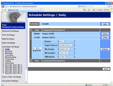
text_image
Schedule Settings / Daily Time Command [Parameter] 1 08:00 Power [OH] 2 17:00 Power [OFF] 3 05:00 Power [OFF] 4 17:00 Input Source [COMPUTER INS] 5 My Image [PAGE OFF] 6 Messenger [TEXT-OFF] 7 Sideshow [START]Time Command [Parameter]
Reset Next Page Tools Top: Network Information Network Settings Port Settings Mail Settings Alert Settings Schedule Settings Daily Sunday Monday Tuesday Wednesday Thursday Friday Saturday Specific date No.1 Specific date No.2 Specific date No.3 Specific date No.4 Specific date No.5 Date / Time Settings Security SettingsDisplays and configures schedule settings.
| Item | Description |
| Daily | Configures the daily schedule. |
| Sunday | Configures the Sunday schedule. |
| Monday | Configures the Monday schedule. |
| Tuesday | Configures the Tuesday schedule. |
| Wednesday | Configures the Wednesday schedule. |
| Thursday | Configures the Thursday schedule. |
| Friday | Configures the Friday schedule. |
| Saturday | Configures the Saturday schedule. |
| Specific date No.1 | Configures the specific date (No.1) schedule. |
| Specific date No.2 | Configures the specific date (No.2) schedule. |
| Specific date No.3 | Configures the specific date (No.3) schedule. |
| Specific date No.4 | Configures the specific date (No.4) schedule. |
| Specific date No.5 | Configures the specific date (No.5) schedule. |
3.7 Schedule Settings (Continued)
The schedule settings are shown below.
| Item | Description |
| Schedule | Click the [Enable] check box to enable the schedule. |
| Date (Month/Day) | Configures the month and date.This item appears only when Specific date (No. 1-5) is selected. |
Click the [Apply] button to save the settings.
The current event settings are displayed on the schedule list. To add additional functions and events, set the following items.
| Item | Description | |
| Time | Configures the time to execute commands. | |
| Command[Parameter] | Configures the commands to be executed. | |
| Power | Configures the parameters for power control. | |
| Input Source | Configures the parameters for input switching. | |
| My Image | Configures the parameters for My Image data display. | |
| Messenger | Configures the parameters for Messenger data display. | |
| Slideshow | Configures the Start/Stop parameters for the Slideshow. | |
Click the [Register] button to add new commands to the schedule list.
Click the [Delete] button to delete commands from the schedule list.
Click the [Reset] button to delete all commands and reset the schedule settings from the schedule list.
3.7 Schedule Settings (Continued)
NOTE • After the projector is moved, check the date and time set for the projector before configuring the schedules. Strong shock may make the date and time settings get out of tune.
- Events “My Image” and “Messenger” will not be executed appropriately but result in “schedule execution error” status in case lamp does not light or/and display data are not stored in the projector at the scheduled event execution time.
- Events “Input Source” and “My Image” will not be executed if security feature is enabled and the projector is locked due to the feature.
- Certain error state in the projector (such as temperature error, lamp error) will prevent the projector from appropriate execution of scheduled functions/events.
- If no USB memory device is inserted to the projector or no image data for display exists at the scheduled event time, a schedule execution error occurs against the scheduled Slideshow event.
- When you start the Slideshow, input source will be automatically switched to the USB TYPE A port.
- Image files stored in the root directory of the USB memory device will be displayed for the scheduled Slideshow.
- Please refer to Troubleshooting in the Operating Guide in case scheduled functions/events are not executed appropriately as you've set.
3.8 Date/Time Settings
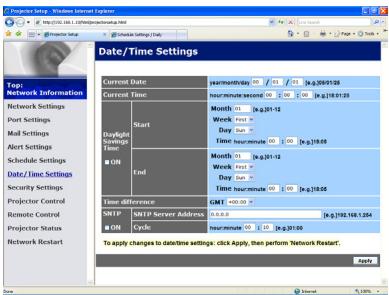
text_image
Project Setup - Windows Internet Explorer http://102.108.1.13@networkinformation.html Project Setup - Satellite Setup Date/Time Settings Top: Network Information Current Date year: 09/01/06 Current Time hour: 00:00:00 e.g. 09/01/06 Daylight Batinger Time Start Month 1 (e.g.01-12) Week Next Day Num Time nanmute 00 (e.g.10/06) End Month 1 (e.g.01-12) Week Next Day Num Time nanmute 00 (e.g.10/06) Project Control Remote Control Project Status Network Resetart Time difference GM1 = 0.000 SFTP SMTP Server Address 0.0.0 ON Cycle Hour: 00:12 e.g.01/06 To apply changes to datetime settings: click Apply, then perform Network Resetart. ApplyDisplays and configures the date and time settings.
| Item | Description | ||
| Current Date | Configures the current date in year/month/day format. | ||
| Current Time | Configures the current time in hour:minute:second format. | ||
| Daylight Savings Time | Click the [ON] check box to enable daylight savings time and set the following items. | ||
| Start | Configures the date and time daylight savings time begins. | ||
| Month | |||
| Week | |||
| Day | |||
| Time | |||
| hour | |||
| minute | |||
| End | Configures the day of the week daylight savings time begins (Sun, Mon, Tue, Wed, Thu, Fri, Sat). | ||
| Time | |||
| hour | |||
| minute | |||
| Item | Description | ||
| Time difference | Configures the time difference. Set the same time difference as the one set on your computer. If unsure, consult your IT manager. | ||
| SNTP | Click the [ON] check box to retrieve Date and Time information from the SNTP server and set the following items. | ||
| SNTP Server Address | |||
| Cycle | |||
Click the [Apply] button to save the settings.
NOTE • The new configuration settings are activated after restarting the network connection. When the configuration settings are changed, you must restart the network connection. You can restart the network connection by clicking the [Network Restart] on the main menu.
- If you connect the projector to an existing network, consult a network administrator before setting server addresses.
- To enable the SNTP function, the time difference must be set.
- The projector will retrieve Date and Time information from the time server and override time settings when SNTP is enabled.
- The internal clock's time may not remain accurate. Using SNTP is recommended to maintain accurate time.
3.9 Security Settings
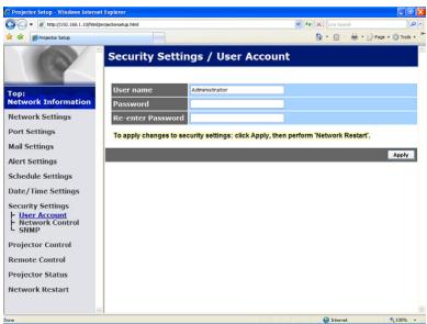
text_image
Security Settings / User Account User Name Administrator Password No enter Password To apply changes to security settings: click Apply, then perform 'Network Restart'; Apply UpdateDisplays and configures passwords and other security settings.
| Item | Description | |
| User Account | Configures the user name and password. | |
| User name | Configures the user name.The length of the text can be up to 32 alphanumeric characters. | |
| Password | Configures the password.The length of the text can be up to 255 alphanumeric characters. | |
| Re-enter Password | Reenter the above password for verification. | |
| Network Control | Configures the Authentication password for the command control. | |
| Authentication Password | Configures the Authentication password. The length of the text can be up to 32 alphanumeric characters. | |
| Re-enter Authentication Password | Reenter the above password for verification. | |
| SNMP | Configures the community name if SNMP is used. | |
| Community name | Configures the community name. The length of the text can be up to 64 alphanumeric characters. | |
Click the [Apply] button to save the settings.
NOTE • The new configuration settings are activated after restarting the network connection. When the configuration settings are changed, you must restart the network connection. You can restart the network connection by clicking the [Network Restart] on the main menu.
- Only numbers ‘0-9’ and alphabet ‘a-z’, ‘A-Z’ can be used.
3.10 Projector Control
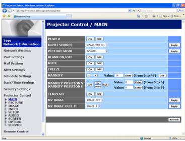
text_image
Projector Control / MAIN Top: Network Information POWER INPUT SOURCE PCCTURE BOOK CLASS HISTORY MULTI FREET MAGNIFY MAGNIFY POSITION V MAGNIFY POSITION H TEMPLATE MY IMAGE MY IMAGE DELETE Value: 0.00 Value: 0.00 Value: 0.00 Value: 0.00 Value: 0.00 Value: 0.00 Value: 0.00 Value: 0.00 Value: 0.00 Value: 0.00 Value: 0.00 Value: 0.00 Value: 0.00 Value: -1.00%The items shown in the table below can be performed using the Projector Control menu.
Select an item with the mouse.
Most of the items have a submenu. Refer to the table below for details.
NOTE • The setting value may not match with the actual value if the user changes the value manually. In that case, please refresh the page by clicking the [Refresh] button.
Controls the projector.
| Item | Description | |
| MAIN | ||
| POWER | Turns the power on/off. | |
| INPUT SOURCE | Selects the input source. | |
| PICTURE MODE | Selects the picture mode setting. | |
| BLANK ON/OFF | Turns Blank on/off. | |
| MUTE | Turns Mute on/off. | |
| FREEZE | Turns Freeze on/off. | |
| MAGNIFY | Controls the magnify setting.In some input signal sources, it might stop “Magnify” even though it does not reach to maximum setting value. | |
| MAGNIFY POSITION V | Adjusts the vertical magnify position. | |
| MAGNIFY POSITION H | Adjusts the horizontal magnify position. | |
| TEMPLATE | Turns template on/off. | |
| MY IMAGE | Selects MY IMAGE data. | |
| MY IMAGE DELETE | Deletes MY IMAGE data. | |
| PICTURE | ||
| BRIGHTNESS | ||
| CONTRAST | ||
| GAMMA | ||
| COLOR TEMP | ||
| COLOR | ||
| TINT | ||
| SHARPNESS | ||
| ACTIVE IRIS | ||
| MYMEMORY SAVE | ||
| MYMEMORY RECALL | ||
| IMAGE | ||
| ASPECT | ||
| OVER SCAN | ||
| V POSITION | ||
| H POSITION | ||
| H PHASE | ||
| H SIZE | ||
| AUTO ADJUST EXECUTE | ||
| INPUT | ||
| PROGRESSIVE | ||
| VIDEO NR | ||
| COLOR SPACE | ||
| COMPONENT | ||
| S-VIDEO FORMAT | ||
| C-VIDEO FORMAT | ||
| HDMI FORMAT | ||
| HDMI RANGE | ||
| COMPUTER IN1 | ||
| COMPUTER IN2 | ||
| FRAME LOCK - COMPUTER IN1 | ||
| FRAME LOCK - COMPUTER IN2 | ||
| FRAME LOCK - HDMI | ||
| SETUP | ||
| AUTO KEYSTONE EXECUTE | Performs the automatic keystone distortion setting. | |
| KEYSTONE V | Adjusts the vertical keystone distortion setting. | |
| KEYSTONE H | Adjusts the horizontal keystone distortion setting. | |
| PERFECT FIT | Adjusts the shape of the projected image in each of the corners and sides. | |
| AUTO ECO MODE | Turns on/off the automatic eco mode function. | |
| ECO MODE | Selects the eco mode. | |
| MIRROR | Selects the mirror status. | |
| STANDBY MODE | Selects the standby mode. | |
| MONITOR OUT - COMPUTER IN1 | Assigns the MONITOR OUT when the COMPUTER IN1 input port is selected. | |
| MONITOR OUT - COMPUTER IN2 | Assigns the MONITOR OUT when the COMPUTER IN2 input port is selected. | |
| MONITOR OUT - LAN | Assigns the MONITOR OUT when the LAN input port is selected. | |
| MONITOR OUT - USB TYPE A | Assigns the MONITOR OUT when the USB TYPE A input port is selected. | |
| MONITOR OUT - USB TYPE B | Assigns the MONITOR OUT when the USB TYPE B input port is selected. | |
| MONITOR OUT - HDMI | Assigns the MONITOR OUT when the HDMI input port is selected. | |
| MONITOR OUT - COMPONENT | Assigns the MONITOR OUT when the COMPONENT input port is selected. | |
| MONITOR OUT - S-VIDEO | Assigns the MONITOR OUT when the S-VIDEO input port is selected. | |
| MONITOR OUT - VIDEO | Assigns the MONITOR OUT when the VIDEO input port is selected. | |
| MONITOR OUT - STANDBY | Assigns the MONITOR OUT in the standby mode. | |
| AUDIO | ||
| VOLUME | Adjusts the volume setting. | |
| SPEAKER | Turns the built-in speaker on/off. | |
| AUDIO SOURCE - COMPUTER IN1 | Assigns the AUDIO SOURCE - COMPUTER IN1 input port. | |
| AUDIO SOURCE - COMPUTER IN2 | Assigns the AUDIO SOURCE - COMPUTER IN2 input port. | |
| AUDIO SOURCE - LAN | Assigns the AUDIO SOURCE - LAN input port. | |
| AUDIO SOURCE - USB TYPE A | Assigns the AUDIO SOURCE - USB TYPE A input port. | |
| AUDIO SOURCE - USB TYPE B | Assigns the AUDIO SOURCE - USB TYPE B input port. | |
| AUDIO SOURCE - HDMI | Assigns the AUDIO SOURCE - HDMI input port. | |
| AUDIO SOURCE - COMPONENT | Assigns the AUDIO SOURCE - COMPONENT input port. | |
| AUDIO SOURCE - S-VIDEO | Assigns the AUDIO SOURCE - S-VIDEO input port. | |
| AUDIO SOURCE - VIDEO | Assigns the AUDIO SOURCE - VIDEO input port. | |
| AUDIO SOURCE - STANDBY | Assigns the AUDIO SOURCE in the standby mode. | |
| HDMI AUDIO | Selects the HDMITM audio setting. | |
| MIC LEVEL | Selects the microphone level. | |
| MIC VOLUME | Adjusts the microphone volume setting. | |
| SCREEN | ||
| LANGUAGE | Selects the language for the OSD. | |
| MENU POSITION V | Adjusts the vertical Menu position. | |
| MENU POSITION H | Adjusts the horizontal Menu position. | |
| BLANK | Selects the Blank mode. | |
| START UP | Selects the start up screen mode. | |
| MyScreen Lock | Turns MyScreen lock function on/off. | |
| MESSAGE | Turns the message function on/off. | |
| TEMPLATE | Selects the template setting. | |
| C.C. - DISPLAY | Selects Closed Caption DISPLAY setting. | |
| C.C. - MODE | Selects Closed Caption MODE setting. | |
| C.C. - CHANNEL | Selects Closed Caption CHANNEL setting. | |
| OPTION | ||
| AUTO SEARCHTurns the automatic signal search function on/off. | ||
| AUTO KEYSTONETurns the automatic keystone distortion correction function on/off. | ||
| DIRECT POWER ONTurns the direct power on function on/off. | ||
| AUTO POWER OFFConfigures the timer to shut off the projector when no signal is detected. | ||
| USB TYPE BSelects the USB TYPE B setting. | ||
| MY BUTTON-1Assigns the functions for the MY BUTTON-1 button on the included remote control. | ||
| MY BUTTON-2Assigns the functions for the MY BUTTON-2 button on the included remote control. | ||
| MY SOURCESelects the My Source setting. | ||
| REMOTE FREQ. - NORMALTurns the remote control signal frequency normal function on/off. | ||
| REMOTE FREQ. - HIGHTurns the remote control signal frequency high function on/ off. | ||
3.10 Projector Control (Continued)
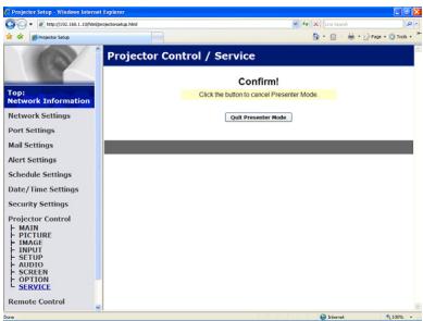
text_image
Projector Setup - Windows Internet Explorer http://123.108.com/sinaiaa.html Projector Setup Projector Control / Service Confirm! Click the button to cancel Presenter Mode Quit Presenter Mode Top: Network Information Network Settings Port Settings Mail Settings Alert Settings Schedule Settings Date / Time Settings Security Settings Projector Control MAIN PICTURE IMAGE INPUT SETUP AUDIO SCREEN OPTION SERVICE Remote ControlThe items shown in the table below can be performed using the Projector Control menu. Click the [Quit Presenter Mode].
| Item | Description |
| SERVICE | |
| Quit Presenter Mode | Quit compulsorily from the Presenter mode. |
3.11 Remote Control
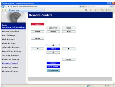
text_image
Projector Setup - Windows Internet Explorer http://102.103.1.108@projectorsetup.html Projector Setup Remote Control TOP: Network Information Network Settings Port Settings Mail Settings Alert Settings Schedule Settings Date/Time Settings Security Settings Projector Control Remote Control Projector Status Network Resetart FORMS COMPUTER VIDEO BLANK FREEZI NOTE MENU ENTER RESET PAGE UP PAGE DOWN SELECT SHOWYou can use your Web browser to control the projector.
- Do not attempt to control the projector with the projector's remote control and via your Web browser at the same time. It may cause some operational errors in the projector.
The functions on the bundled remote control are assigned to the Web Remote Control screen.
| Item | Description |
| POWER | Assigned the same operation as STANDBY/ON button. |
| COMPUTER | Assigned the same operation as COMPUTER button. |
| VIDEO | Assigned the same operation as VIDEO button. |
| BLANK | Assigned the same operation as BLANK button. |
| FREEZE | Assigned the same operation as FREEZE button. |
| MUTE | Assigned the same operation as MUTE button. |
| MENU | Assigned the same operation as MENU button. |
| ▲ | Assigned the same operation as ▲ button. |
| ▼ | Assigned the same operation as ▼ button. |
| ◀ | Assigned the same operation as ◀ button. |
| ▶ | Assigned the same operation as ▶ button. |
| ENTER | Assigned the same operation as ENTER button. |
| RESET | Assigned the same operation as RESET button. |
| PAGE UP | Assigned the same operation as PAGE UP button. |
| PAGE DOWN | Assigned the same operation as PAGE DOWN button. |
| SLIDESHOW | Starts the Slideshow. |
NOTE • The Web Remote Control does not support repeat function that performs an action while holding a button clicked down.
- Since the repeat function is not available, click the button repeatedly as many times as you require.
- Even if you hold the button clicked down for a while, the Web Remote Control sends your request command one time only. Release the button, then click it again.
- When the [POWER] button is pushed, a message window comes up to confirm the operation. To control the power, push [OK], otherwise push [Cancel].
- The [PAGE DOWN] and [PAGE UP] buttons on the Web Remote Control cannot be used as mouse emulation function of the projector.
3.12 Projector Status
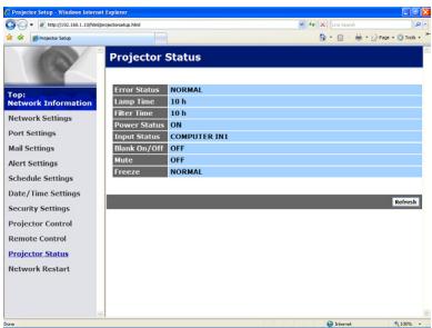
text_image
Projector Setup - Windows Internet Explorer http://102.103.1.108/ projects@projector.net Projector Setup Top: Network Information Network Settings Port Settings Mail Settings Alert Settings Schedule Settings Date/ Time Settings Security Settings Projector Control Remote Control Projector Status Network Resetart Projector Status Error Status NORMAL Lamp Time 10 h Fiber Time 10 h Power Status ON Input Status COMPUTER IN1 Block On/Off OFF Mate OFF Freeze NORMAL RefreshDisplays and configures the current projector status.
| Item | Description |
| Error Status | Displays the current error status |
| Lamp Time | Displays the usage time for the current lamp. |
| Filter Time | Displays the usage time for the current filter. |
| Power Status | Displays the current power status. |
| Input Status | Displays the current input signal source. |
| Blank On/Off | Displays the current Blank on/off status. |
| Mute | Displays the current Mute on/off status. |
| Freeze | Displays the current Freeze status. |
3.13 Network Restart

text_image
Projector Setup - Windows Internet Explorer http://102.168.1.139@projector sunset.html Projector Setup Top: Network Information Network Settings Port Settings Mail Settings Alert Settings Schedule Settings Date/Time Settings Security Settings Projector Control Remote Control Projector Status Network Restart Confirm! Restarting requires you to re-log in order to further control or configure the projector via a web browser. Restart! BackRestarts the projector's network connection.
| Item | Description |
| Restart | Restarts the projector's network connection in order to activate new configuration settings. |
NOTE • Restarting requires you to re-log on in order to further control or configure the projector via a web browser. Wait 30 seconds or more after clicking the [Restart] button to log on again.
4. My Image Function
The projector can display still images that are transferred via the network.
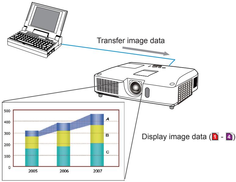
flowchart
graph TD
    A["Laptop"] -->|Transfer image data| B[" projector"]
    B --> C["Display image data (1 - 4)"]
    subgraph Image Data
        D["2005: A: 300, B: 200, C: 150"]
    end
    D --> E["2006: A: 350, B: 250, C: 180"]
    E --> F["2007: A: 450, B: 300, C: 200"]
    style D fill:#f9f,stroke:#333
    style E fill:#bbf,stroke:#333
    style F fill:#dfd,stroke:#333
MY IMAGE transmission requires an exclusive application for your computer. Use the application to transfer the image data.
It can be downloaded from the ViewSonic web site (http://www.viewsonic.com/products/pro9500.htm).
Refer to the manual for the application for instructions.
To display the transferred image, select the MY IMAGE item in the NETWORK menu. For more information, please see the description of the MY IMAGE item of the NETWORK menu. (NETWORK menu in the Operating Guide)
NOTE • It is possible to allocate the image file up to 4 in the maximum.
- Using MY BUTTON that registered MY IMAGE can display transferred image. (OPTION menu in the Operating Guide)
- The image file also can be displayed by using schedule function from the web browser. Refer to item 7.3 Event Scheduling in detail.
- If you display MY IMAGE data on screen while you are using the USB Display function, the application for the USB Display will be closed. To restart the application, exit the MY IMAGE function, and then the software in the projector, LiveViewerLiteUSB.exe, will run again. (USB Display in the Operating Guide)
4. My Image Function (Continued)
Configure the following items from a web browser when MY IMAGE function is used.
Example: If the IP address of the projector is set to 192.168.1.10:
1) Enter "http://192.168.1.10/" into the address bar of the web browser.
2) Enter your user name and password, and then click the [OK].
3) Click the [Port Settings] on the main menu.
4) Click the [Enable] check box to open the My Image Port (Port: 9716). Click the [Enable] check box for the [Authentication] setting when authentication is required, otherwise clear the check box.
5) Click the [Apply] button to save the settings.

text_image
Port Settings Network Control Port1 (Port:23) Port open Enable Authentication Enable Network Control Port2 (Port:9715) Port open Enable Authentication Enable P.Link Port (Port:4352) Port open Enable Authentication Enable My Image Port (Port:9716) Port open Enable Authentication Enable Messenger Port (Port:9719) Port open Enable Authentication EnableWhen the authentication setting is enabled, the following settings are required.
6) Click the [Security Settings] on the main menu.
7) Select the [Network Control] and enter the desired authentication password.
8) Click the [Apply] button to save the settings.
NOTE • The Authentication Password will be the same for Network Control Port1 (Port: 23), Network Control Port2 (Port: 9715), PJLink™ Port (Port: 4352), My Image Port (Port: 9716) and Messenger Port (Port: 9719).
- The new configuration settings are activated after restarting the network connection. When the configuration settings are changed, you must restart the network connection. You can restart the network connection by clicking the [Network Restart] on the main menu.
5. Messenger Function
The projector can display the text data transferred via the network on the screen. The text data can be displayed on the screen in two ways that displays the text transferred from the computer on real time, and the other chooses and displays the text data from the ones once stored in the projector.
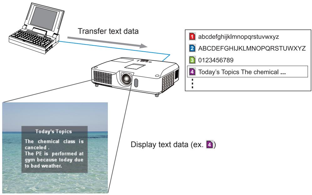
flowchart
graph TD
    A["Transfer text data"] --> B["Device"]
    C["Today's Topics"] --> D["The chemical class is canceled. The PE is performed at gym because today due to bad weather."]
    E["Display text data (ex. 4)"] --> F["Today's Topics The chemical ..."]
Messenger function requires an exclusive application for your computer. To edit, transfer and display the text data, use the application. You can download it from the ViewSonic web site (http://www.viewsonic.com/products/pro9500.htm). Refer to the manual for the application for the details of Messenger function and instructions of the application.
NOTE • It is possible to store the text data up to 12 in the maximum.
- Using MY BUTTON that registered MESSENGER can turn the displaying messenger text on/off. (OPTION menu in the Operating Guide)
- The text file also can be displayed by using schedule function via the web browser. Refer to item 7.3 Event Scheduling for the detail.
5. Messenger Function (Continued)
Configure the following items from a web browser when Messenger function is used.
Example: If the IP address of the projector is set to 192.168.1.10:
1) Enter "http://192.168.1.10/" into the address bar of the web browser.
2) Enter your user name and password, and then click the [OK].
3) Click the [Port Settings] on the main menu.
4) Click the [Enable] check box to open the Messenger Port (Port: 9719). Click the [Enable] check box for the [Authentication] setting when authentication is required, otherwise clear the check box.
5) Click the [Apply] button to save the settings.
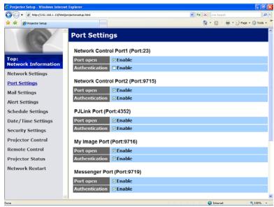
text_image
Port Settings Network Control Port1 (Port:23) Port open Enable Authentication Enable Network Control Port2 (Port:9715) Port open Enable Authentication Enable P.Link Port (Port:4352) Port open Enable Authentication Enable My Image Port (Port:9716) Port open Enable Authentication Enable Messenger Port (Port:9719) Port open Enable Authentication EnableWhen the authentication setting is enabled, the following settings are required.
6) Click the [Security Settings] on the main menu.
7) Select the [Network Control] and enter the desired authentication password.
8) Click the [Apply] button to save the settings.
NOTE • The Authentication Password will be the same for Network Control Port1 (Port: 23), Network Control Port2 (Port: 9715), PJLink™ Port (Port: 4352), My Image Port (Port: 9716) and Messenger Port (Port: 9719).
- The new configuration settings are activated after restarting the network connection. When the configuration settings are changed, you must restart the network connection. You can restart the network connection by clicking the [Network Restart] on the main menu.
6. Network Bridge Function
This projector is equipped with the NETWORK BRIDGE function to perform mutual conversion of a network protocol and a serial interface.
Using the NETWORK BRIDGE function, a computer that is connected with this projector by Ethernet communication can control an external device that is connected with this projector by RS-232C communication as a network terminal.
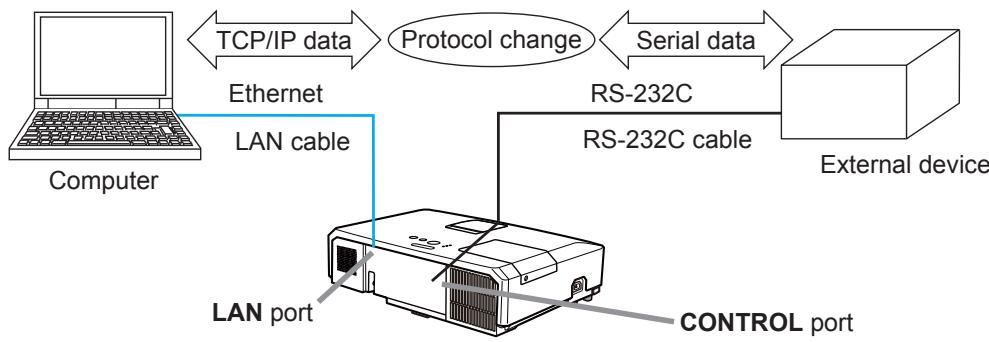
flowchart
graph TD
    A["Computer"] -->|TCP/IP data| B["Ethernet"]
    B -->|Ethernet| C["LAN cable"]
    C --> D["External device"]
    D -->|Serial data| E["RS-232C cable"]
    E --> F["LAN port"]
    F --> G["CONTROL port"]
    style A fill:#f9f,stroke:#333
    style B fill:#ccf,stroke:#333
    style C fill:#cfc,stroke:#333
    style D fill:#fcc,stroke:#333
    style E fill:#cff,stroke:#333
    style F fill:#ffc,stroke:#333
    style G fill:#fcc,stroke:#333
6.1 Connecting devices
1) Connect the projector's LAN port and the computer's LAN port with a LAN cable, for Ethernet communication.
2) Connect the projector's CONTROL port and the device's RS-232C port with an RS-232C cable, for RS-232C communication.
NOTE • Before connecting the devices, read the manuals for the devices to ensure the connection.
For RS-232C connection, check the specifications of each port and use the suitable cable.
6.2 Communication setup
To configure the setup of the communication using NETWORK BRIDGE for the projector, use items in the COMMUNICATION menu. Open the menu of the projector and select the OPTION - SERVICE - COMMUNICATION menu. (OPTION menu > SERVICE > COMMUNICATION in the Operating Guide)
1) Using the COMMUNICATION TYPE menu, select the NETWORK BRIDGE for the CONTROL port.
2) Using the SERIAL SETTINGS menu, select the proper baud rate and parity for the CONTROL port, according to the specification of the RS-232C port of the connected device.
| Item | Condition |
| BAUD RATE | 4800bps/9600bps/19200bps/38400bps |
| PARITY | NONE/ODD/EVEN |
| Data length | 8 bit (fixed) |
| Start bit | 1 bit (fixed) |
| Stop bit | 1 bit (fixed) |
3) Using the TRANSMISSION METHOD menu, set up the proper method for the CONTROL port according to your use.
NOTE • The OFF is selected for the COMMUNICATION TYPE as the default setting.
- Using the COMMUNICATION menu, set up the communication. Remember that an unsuitable setup could cause malfunction of communication.
- When COMMUNICATION TYPE is set to NETWORK BRIDGE, the CONTROL port doesn't accept RS-232C commands.
6.3 Communication port
For the NETWORK BRIDGE function, send the data from the computer to the projector with using the Network Bridge Port that is configured in the “Port Settings” of web browser.
NOTE • Except for 9715, 9716, 9719, 9720, 5900, 5500, 4352 between 1024 and 65535 can be set up as the Network Bridge Port number. It is set to 9717 as the default setting.
6.4 Transmission method
The transmission method can be selected from the menus, only when the NETWORK BRIDGE is selected for the COMMUNICATION TYPE.
(OPTION menu > SERVICE > COMMUNICATION in the Operating Guide)
HALF-DUPLEX FULL-DUPLEX
6.4.1 HALF-DUPLEX
This method lets the projector make two way communication, but only one direction, either transmitting or receiving data, is allowed at a time.
The method does not allow the projector to receive the data from the computer while waiting for response data from an external device. After the projector receives the response data from an external device or the response limit time is past, the projector can receive the data from the computer.
That means that the projector controls transmitting and receiving the data to synchronize the communication.
To use the HALF-DUPLEX method, set up the RESPONSE LIMIT TIME following the instructions below.
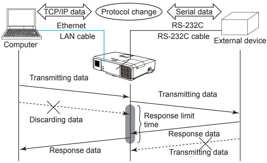
flowchart
graph TD
    A["Computer"] -->|TCP/IP data| B["Ethernet"]
    B --> C["LAN cable"]
    C --> D["RS-232C cable"]
    D --> E["External device"]
    F["Transmitting data"] --> G["Response limit time"]
    H["Discarding data"] --> G
    I["Response data"] --> G
    G --> J["External device"]
    K["Protocol change"] --> L["Serial data"]
    L --> M["External device"]
Using the RESPONSE LIMIT TIME menu, set the waiting time for response data from an external device. (OPTION menu > SERVICE > COMMUNICATION in the Operating Guide)
$$ \mathrm{OFF} \leftrightarrow 1 \mathrm{s} \leftrightarrow 2 \mathrm{s} \leftrightarrow 3 \mathrm{s} (\leftrightarrow \mathrm{OFF}) $$
6.4 Transmission method (Continued)
NOTE • With using the HALF-DUPLEX method, the projector can send out 254 byte data as maximum at once.
- If it is not required to monitor the response data from an external device and the RESPONSE LIMIT TIME is set to OFF, the projector can receive the data from the computer and send it out to an external device continuously.
The OFF is selected as the default setting.
6.4.2 FULL-DUPLEX
This method lets the projector make two way communication, transmitting and receiving data at the same time, without monitoring response data from an external device.
With using this method, the computer and an external device will send the data out of synchronization. If it is required to synchronize them, set the computer to make the synchronization.
NOTE • In case that the computer controls to synchronize transmitting and receiving the data, it may not be able to control an external device well depending on the processing status of the projector.
7. Other Functions
7.1 E-mail Alerts
The projector can automatically send an alert message to the specified e-mail addresses when the projector detects a certain condition that is requiring maintenance or detected an error.
NOTE • Up to five e-mail addresses can be specified.
- The projector may be not able to send e-mail if the projector suddenly loses power.
Mail Settings
To use the projector's e-mail alert function, please configure the following items through a web browser.
Example: If the IP address of the projector is set to 192.168.1.10:
1) Enter "http://192.168.1.10/" into the address bar of the web browser.
2) Enter your user name and password, and then click the [OK].
3) Click the [Mail Settings] and configure each item. Refer to item 3.5 Mail Settings for further information.
4) Click the [Apply] button to save the settings.
NOTE • Click the [Send Test Mail] button in the [Mail Settings] to confirm that the e-mail settings are correct. The following mail will be delivered to the specified addresses.
| Subject line | :Test Mail | <Projector name> |
| Text | :Send Test Mail | |
| Date | <Testing date> | |
| Time | <Testing time> | |
| IP Address | <Projector IP address> | |
| MAC Address | <Projector MAC address> |
7.1 E-mail Alerts (Continued)
5) Click the [Alert Settings] on the main menu to configure the E-mail Alerts settings.
6) Select and configure each alert item. Refer to item 3.6 Alert Setting for further information.
7) Click the [Apply] button to save the settings.
Failure/Warning e-mails are formatted as follows:
| Subject line | : | |
| Text | : | |
| Date | ||
| Time | ||
| IP Address | ||
| MAC Address |
7.2 Projector Management using SNMP
The SNMP (Simple Network Management Protocol) enables to manage the projector information, which is a failure or warning status, from the computer on the network. The SNMP management software will be required on the computer to use this function.
NOTE • It is recommended that SNMP functions be carried out by a network administrator.
- SNMP management software must be installed on the computer to monitor the projector via SNMP.
SNMP Settings
Configure the following items via a web browser to use SNMP.
Example: If the IP address of the projector is set to 192.168.1.10:
1) Enter "http://192.168.1.10/" into the address bar of the web browser.
2) Enter your user name and password, and then click the [OK].
3) Click the [Port Settings] on the main menu.
4) Click the [Download MIB file] to download a MIB file.
NOTE • To use the downloaded MIB file, specify the file by your SNMP manager.
5) Click the [Enable] check box to open the SNMP Port. Set the IP address to send the SNMP trap to when a Failure/Warning occurs.
NOTE • A Network Restart is required after the SNMP Port configuration settings have been changed. Click the [Network Restart] and configure the following items.
6) Click the [Security Settings] on the main menu.
7) Click the [SNMP] and set the community name on the screen that is displayed.
NOTE • A Network Restart is required after the Community name has been changed. Click the [Network Restart] and configure the following items.
8) Configure the settings for Trap transmission of Failures/Warnings. Click the [Alert Settings] on the main menu and select the Failure/Warning item to be configured.
9) Click the [Enable] check box to send out the SNMP trap for Failures/Warnings. Clear the [Enable] check box when SNMP trap transmission is not required.
10) Click the [Apply] button to save the settings.
7.3 Event Scheduling
The scheduling function enables to setup scheduled events including power on / power off. It enables to be “self-management” projector.
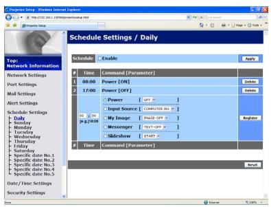
text_image
Schedule Settings / Daily Time Command [Parameter] 1 08:00 Power [OR] 2 17:00 Power [OFF] 3 Input Source COMPUTER INS 4 My Image IMAGE-OFF 5 Messenger TEXT-OFF 6 Sideshow ISTARTTime Command [Parameter]
Logber Reset Security Settings Send Apply Top: Network Information Network Settings Port Settings Mail Settings Alert Settings Schedule Settings Daily Sunday Monday Tuesday Wednesday Thursday Friday Saturday Specific date No.1 Specific date No.2 Specific date No.3 Specific date No.4 Specific date No.5 Date/Time Settings Schedule Settings / Daily Schedule Enable ApplyNOTE • You can schedule the following control events: Power, Input Source, My Image, Messenger, Slideshow.
- The power on / off event has the lowest priority among the all events that are defined at the same time.
- There are 3 types of Scheduling, 1) daily 2) weekly 3) specific date.
- The priority for scheduled events is as follows 1) specific date 2) weekly 3) daily.
- Up to five specific dates are available for scheduled events. Priority is given to those with the lower numbers when more than one event has been scheduled for the same date and time (e.g., ‘Specific date No. 1’ has priority over ‘Specific date No. 2’ and so on.
- Be sure to set the date and time before enabling scheduled events.
7.3 Event Scheduling(Continued)
Schedule Settings
Schedule settings can be configured from a web browser.
Example: If the IP address of the projector is set to 192.168.1.10:
1) Enter "http://192.168.1.10/" into the address bar of the web browser.
2) Enter your user name and password, and then click the [OK].
3) Click the [Schedule Settings] on the main menu and select the required schedule item. For example, if you want to perform the command every Sunday, please select the [Sunday].
4) Click the [Enable] check box to enable scheduling.
5) Enter the date (month/day) for specific date scheduling.
6) Click the [Apply] button to save the settings.
7) After configure the time, command and parameters, click the [Register] to add the new event.
8) Click the [Delete] button when you want to delete a schedule.
There are three types of scheduling.
1) Daily: Perform the specified operation at a specified time every day.
2) Sunday \~ Saturday: Perform the specified operation at the specified time on a specified day of the week.
3) Specific date: Perform the specified operation on the specified date and time.
NOTE • In standby mode, the POWER indicator will flash green for approx. 3 seconds when at least 1 “Power ON” schedule is saved. • When the schedule function is used, the power cord must be connected to the projector and the outlet. The schedule function does not work when the breaker in a room is tripped. The power indicator will lights orange or green when the projector is receiving AC power.
7.3 Event Scheduling(Continued)
Date/Time Settings
The Date/Time setting can be adjusted via a web browser.
Example: If the IP address of the projector is set to 192.168.1.10:
1) Enter "http://192.168.1.10/" into the address bar of the web browser.
2) Enter your user name and password, and then click the [OK].
3) Click the [Date/Time Settings] on the main menu and configure each item.
Refer to item 3.8 Date/Time Settings for further information.
4) Click the [Apply] button to save the settings.
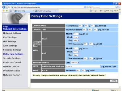
text_image
Project Setup - Windows Internet Explorer http://102.168.1.10@darkwater.net Current Date: 30/07/2019 Current Time: 00:00:00 Daylight Savings Time Start ON End Current Time: 00:00:00 Month 00:00:00 Week 00:00:00 Day 00:00:00 Time maximum 00:00:00 Month 00:00:00 Week 00:00:00 Day 00:00:00 Time maximum 00:00:00 [ug.128.01.15] [ug.128.01.15] Project Control Remote Control Project Status Network Reset Time difference GM1 +48.88 SMTP SMTP Server Address 8.8.8.8 ON Cycle hour-time 45 123 [ug.31.15] To apply changes to datetime settings, click Apply, then perform Network Reset! ApplyNOTE • The battery for the built in clock may be dead if the clock loses time even when the date and time have been set correctly. Replace the battery by following the instructions on replacing the battery.
(Replacing the internal clock battery in the Quick Start Guide)
- The internal clock's time may not remain accurate. Using SNTP is recommended to maintain accurate time.
7.4 Command Control via the Network
You can configure and control the projector via the network using RS-232C commands.
Communication Port
The following two ports are assigned for the command control.
TCP #23 (Network Control Port1 (Port: 23))
TCP #9715 (Network Control Port2 (Port: 9715))
NOTE • Command control is available only via the specified port above.
Command Control Settings
Configure the following items from a web browser when command control is used.
Example: If the IP address of the projector is set to 192.168.1.10:
1) Enter "http://192.168.1.10/" into the address bar of the web browser.
2) Enter your user name and password, and then click the [OK].
3) Click the [Port Settings] on the main menu.

text_image
Port Settings Network Control Port1 (Port:23) Port open Enable Authentication Enable Network Control Port2 (Port:9715) Port open Enable Authentication Enable P Link Port (Port:4352) Port open Enable Authentication Enable My Image Port (Port:9716) Port open Enable Authentication Enable Messenger Port (Port:9719) Port open Enable Authentication Enable4) Click the [Enable] check box to open Network Control Port1 (Port: 23) to use TCP #23. Click the [Enable] check box for the [Authentication] setting when authentication is required, otherwise clear the check box.
5) Click the [Enable] check box to open Network Control Port2 (Port: 9715) to use TCP #9715. Click the [Enable] check box for the [Authentication] setting when authentication is required, otherwise clear the check box.
6) Click the [Apply] button to save the settings.
7.4 Command Control via the Network (Continued)
When the authentication setting is enabled, the following settings are required.
7) Click the [Security Settings] on the main menu.
8) Click the [Network Control] and enter the desired authentication password.
* See NOTE.
9) Click the [Apply] button to save the settings.
NOTE • The Authentication Password will be the same for Network Control Port1 (Port: 23), Network Control Port2 (Port: 9715), PJLink™ Port (Port: 4352), My Image Port (Port: 9716) and Messenger Port (Port: 9719).
- The new configuration settings are activated after restarting the network connection. When the configuration settings are changed, you must restart the network connection. You can restart the network connection by clicking the [Network Restart] on the main menu.
7.4 Command Control via the Network (Continued)
Command Format
Command formats differ among the different communication ports.
- TCP #23
You can use the RS-232C commands without any changes. The reply data format is the same as the RS-232C commands.
However, the following reply will be sent back in the event of authentication failure when authentication is enabled.
| Reply | Error code | |
| 0x1F | 0x04 | 0x00 |
- TCP #9715
Send Data format
The following formatting is added to the header (0 x 02), Data length (0 x 0D), Checksum (1 byte) and Connection ID (1 byte) of the RS-232C commands.
| Header | Data length | RS-232Ccommand | Check Sum | Connection ID |
| 0x02 | 0x0D | 13 bytes | 1 byte | 1 byte |
Header → 0x02, Fixed
Data length → RS-232C commands byte length (0x0D, Fixed)
RS-232C command → RS-232C commands that start with 0xBE 0xEF (13 bytes)
Check Sum → This is the value to make zero on the addition of the lower 8 bits from the header to the checksum.
Connection ID → Random value from 0 to 255 (This value is attached to the reply data)
7.4 Command Control via the Network (Continued)
Reply Data format
The connection ID (the data is same as the connection ID data on the sending data format) is attached to the RS-232C commands reply data.
| Reply | Connection ID |
| 0x06 | 1 byte |
| Reply | Connection ID |
| 0x15 | 1 byte |
| Reply | Error code | Connection ID |
| 0x1C | 2 bytes | 1 byte |
| Reply | Data | Connection ID |
| 0x1D | 2 bytes | 1 byte |
| Reply | Status code | Connection ID |
| 0x1F | 2 bytes | 1 byte |
| Reply | Authentication Error code | Connection ID | |
| 0x1F | 0x04 | 0x00 | 1 byte |
7.4 Command Control via the Network (Continued)
Automatic Connection Break
The TCP connection will be automatically disconnected after there is no communication for 30 seconds after being established.
Authentication
The projector does not accept commands without authentication success when authentication is enabled. The projector uses a challenge response type authentication with an MD5 (Message Digest 5) algorithm.
When the projector is using a LAN, a random 8 bytes will be returned if authentication is enabled. Bind this received 8 bytes and the Authentication Password and digest this data with the MD5 algorithm and add this in front of the commands to send.
Following is a sample if the Authentication Password is set to “password” and the random 8 bytes are “a572f60c”.
1) Connect the projector.
2) Receive the random 8 bytes "a572f60c" from the projector.
3) Bind the random 8 bytes "a572f60c" and the Authentication Password "password" and it becomes "a572f60cpassword".
4) Digest this bind "a572f60cpassword" with MD5 algorithm. It will be "e3d97429adffa11bce1f7275813d4bde".
5) Add this “e3d97429adffa11bce1f7275813d4bde” in front of the commands and send the data.
Send “e3d97429adffa11bce1f7275813d4bde”+command.
6) When the sending data is correct, the command will be performed and the reply data will be returned. Otherwise, an authentication error will be returned.
NOTE • As for the transmission of the second or subsequent commands, the authentication data can be omitted when the same connection.
- Troubleshooting
| Problem | Likely Cause | Things to Check | Reference Page Number | |
| No image | The projector is not turned on. | Is the projector's lamp on? | 18, 100 in the Operating Guide | |
| The projector's input source isn't switched to LAN. | Is the projector switched to LAN? | 19, 20 in the Operating Guide | ||
| Connection to the Network | The projector that you want to connect to is nowhere to be found on the list of available projectors | The computer and/or projector's network settings are not configured correctly. | Check the network configurations of the computer and projector. If you change the projector's settings, turn off the projector's AC power and then turn it on again. If you simply put the projector in STANDBY power mode and then turn it on again, the new settings might not take effect. | - |
| Firewall software other than Windows® Firewall is installed in your computer. | Refer to the manual for the firewall software and take one of the following actions: - Exclude the “LiveViewer” from blocking item list - Disable the firewall while using the “LiveViewer” | - | ||
| Can't communicate | The computer and/or projector's network settings are not configured correctly. | Check the network configurations of the computer and projector. | - | |
| An access point is used, and your computer is connected to the access point via wireless LAN. | Use network utilities that may come with your computer or wireless LAN card to establish wireless network connection. For detail, refer to the manual of the computer or the card. | - | ||
| Network Presentation | The projected image is rather slow compared to that of the computer | The projector isn't capable of relaying dynamic images such as PowerPoint® animation at full speed. | Switching the priority to 'Transmission Speed' under the options menu may help to improve speed. | 41 |
| The compression rate being used for transferring the images is too low. | Switching the priority to 'Transmission Speed' under the options menu may help to improve speed. | 41 | ||
| Can't display the movies correctly. | In some combinations of computer's video card and application software, there is a possibility that true image - especially movies played by media player - cannot be transferred to the projector with the "LiveViewer". | If there is a video acceleration level adjustment function in your application, please try to adjust it. Refer your application manual in detail. | - | |
| Network connection between the computer and projector is disconnected when computer display resolution is changed during Network Presentation. | The computer-Projector network connection might be disconnected when computer display resolution is changed while displaying picture. | Please re-connect using "Connect button" after changing computer display resolution, or change display resolution before connecting with the "LiveViewer". | 37 | |
| Images contain lots of interference. | The compression rate being used for transferring the images is too high. | Try setting the priority to 'Image Quality' in the "LiveViewer" Option menu. You may experience a drop in speed. | 41 | |
| Neither transparency nor translucency effects (Glass) | Using the "LiveViewer" with Windows® Aero® mode. | The "LiveViewer" does not support these features of Windows Vista® Aero®. | - | |
| Problem | Likely Cause | Things to Check | Reference Page Number | |
| Others- Information from the projector to computer is not correct or completed- The projector does not respond- Image on screen is frozen. | Communication between the projector and computer is not working well.NETWORK Functions of the projector is not working well. | Try “RESTART” in SERVICE menu under the NETWORK menu. | 70 in the Operating Guide | |
Appendix
RS-232C Communication
When the projector connects to the computer by RS-232C communication, the projector can be controlled with RS-232C commands from the computer.
For details of RS-232C commands, refer to RS-232C Communication / Network command table.
Connection
- Turn off the projector and the computer.
- Connect the projector's CONTROL port and the computer's RS-232C port with a RS-232C cable (cross). Use the cable that fulfills the specification shown in figure
- Turn the computer on, and after the computer has started up turn the projector on.
- Set the COMMUNICATION TYPE to OFF. (OPTION menu - SERVICE - COMMUNICATION in the Operating Guide)
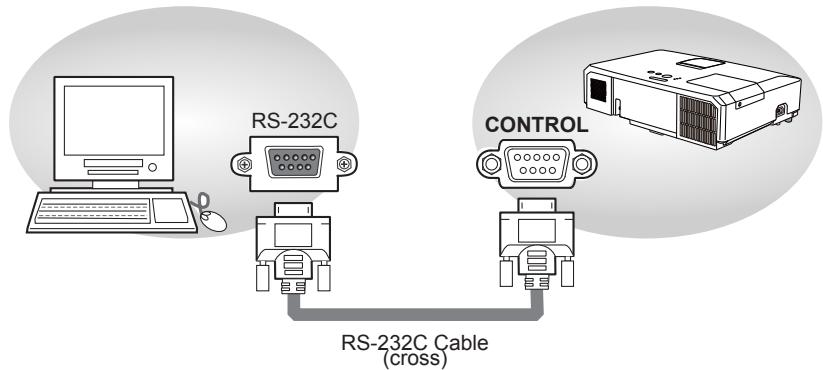
text_image
RS-232C CONTROL RS-232C Cable (cross)RS-232C port of the computer

CONTROL port of the projector

text_image
①②③④⑤ ⑥⑦⑧⑨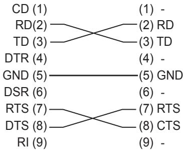
flowchart
graph LR
    CD["CD (1)"] --> RD["RD(2)"]
    RD --> TD["TD (3)"]
    TD --> DTR["DTR (4)"]
    DTR --> GND["GND (5)"]
    GND --> DSR["DSR (6)"]
    DSR --> RTS["RTS (7)"]
    RTS --> DTS["DTS (8)"]
    DTS --> RI["RI (9)"]

    subgraph Path1
        direction TB
        RD --> TD
        TD --> GND
        GND --> DSR
        RTS --> DTS
        RI --> GND
        TD --> RTS
        TD --> CTS
    end

    subgraph Path2
        direction TB
        RD --> TD
        TD --> GND
        GND --> DSR
        DSR --> RTS
        RTS --> DTS
        DTS --> RI
    end

    note1["(1) -"]
    note2["(2) RD"]
    note3["(3) TD"]
    note4["(4) -"]
    note5["(5) GND"]
    note6["(6) -"]
    note7["(7) RTS"]
    note8["(8) CTS"]
    note9["(9) -"]
Communication settings
1. Protocol
19200bps,8N1
- Command format ("h" shows hexadecimal)
| Byte Number | 0 | 1 | 2 | 3 | 4 | 5 | 6 | 7 | 8 | 9 | 10 | 11 | 12 |
| CommandAction | Header | Data | |||||||||||
| Header code | Packet | Data size | CRC flag | Action | Type | Setting code | |||||||
| L | H | L | H | L | H | L | H | L | H | L | H | ||
| Change setting to desired value [(cL)(cH)] by [(eL)(eH)]. | 03h | 06h | 00h | (aL) | (aH) | 01h | 00h | (bL) | (bH) | (cL) | (cH) | ||
| Read projector internal setup value [(bL) (bH)]. | (aL) | (aH) | 02h | 00h | (bL) | (bH) | 00h | 00h | |||||
| Increment setup value [(bL)(bH)] by 1. | (aL) | (aH) | 04h | 00h | (bL) | (bH) | 00h | 00h | |||||
| Decrement setup value [(bL)(bH)] by 1. | (aL) | (aH) | 05h | 00h | (bL) | (bH) | 00h | 00h | |||||
| Run a command [(bL)(bH)]. | (aL) | (aH) | 06h | 00h | (bL) | (bH) | 00h | 00h | |||||
[Header code] [Packet] [Data size]
Set [BEh, EFh, 03h, 06h, 00h] to byte number 0\~4.
[CRC flag]
For byte number 5, 6, refer to RS-232C Communication / Network command table.
[Action]
Set functional code to byte number 7, 8.
Refer to the Communication command table.
[Type] [Setting code]
For byte number 9 \~ 12, refer to RS-232C Communication / Network command table.
3. Response code / Error code ("h" shows hexadecimal)
(1) ACK reply : 06h
When the projector receives the Set, Increment, Decrement or Execute command correctly, the projector changes the setting data for the specified item by [Type], and it returns the code.
(2) NAK reply : 15h
When the projector cannot understand the received command, the projector returns the error code. In such a case, check the sending code and send the same command again.
(3) Error reply : 1Ch + 0000h
When the projector cannot execute the received command for any reasons, the projector returns the error code. In such a case, check the sending code and the setting status of the projector.
(4) Data reply : 1Dh + xxxxh
When the projector receives the GET command correctly, the projector returns the response code and 2 bytes of data.
NOTE • For connecting the projector to your devices, please read the manual for each devices, and connect them correctly with suitable cables.
- Operation cannot be guaranteed when the projector receives an undefined command or data.
- Provide an interval of at least 40ms between the response code and any other code.
- The projector outputs test data when the power supply is switched ON, and when the lamp is lit. Ignore this data.
- Commands are not accepted during warm-up.
- When the data length is greater than indicated by the data length code, the projector ignore the excess data code. Conversely when the data length is shorter than indicated by the data length code, the projector returns the error code to the computer.
Command Control via the Network
When the projector connects network, the projector can be controlled with RS-232C commands from the computer with web browser.
For details of RS-232C commands, refer to RS-232C Communication / Network command table.
Connection
- Turn off the projector and the computer.
- Connect the projector's LAN port and the computer's LAN port with a LAN cable. Use the cable that fulfills the specification shown in figure (Use CAT-5 or greater LAN Cable when LAN ports are used)
- Turn the computer on, and after the computer has started up turn the projector on.
LAN cable (CAT-5 or greater)
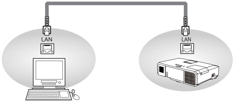
flowchart
graph TD
    A["Computer"] --> B["LAN"]
    B --> C["Printer"]
    D["Printer"] --> E["LAN"]
    E --> F["Printer"]
Communicaion Port
The following two ports are assigned for the command control.
TCP #23
TCP #9715
Configure the following items form a web browser when command control is used.
| Port Settings | ||
| Network Control Port1 (Port: 23) | Port open | Click the [Enable] check box to open [Network Control Port1 (Port: 23)] to use TCP #23. Default setting is “Enable”. |
| Authentication | Click the [Enable] check box for the [Authentication] setting when authentication is required. Default setting is “Disable”. | |
| Network Control Port2 (Port: 9715) | Port open | Click the [Enable] check box to open [Network Control Port2 (Port: 9715)] to use TCP #9715. Default setting is “Enable”. |
| Authentication | Click the [Enable] check box for the [Authentication] setting when authentication is required. Default setting is “Enable”. | |
When the authentication setting is enabled, the following settings are required.
| Security Settings | ||
| Network Control | Authentication Password | Enter the desired authentication password. This setting will be the same for [Network Control Port1 (Port: 23)] and [Network Control Port2 (Port: 9715)]. Default setting is blank. |
| Re-enter Authentication Password | ||
Command control settings
[TCP #23]
1. Command format
Same as RS-232C communication, refer to RS-232C Communicaton command format.
2. Response code / Error code ("h" shows hexadecimal)
Four of the response / error code used for TCP#23 are the same as RS-232C Communication (1)\~(4). One authentication error reply (5) is added.
(1) ACK reply : 06h
Refer to RS-232C communication.
(2) NAK reply : 15h
Refer to RS-232C communication.
(3) Error reply : 1Ch + 0000h
Refer to RS-232C communication.
(4) Data reply : 1Dh + xxxxh
Refer to RS-232C communication.
(5) Authentication error reply : 1Fh + 0400h
When authentication error occurred, the projector returns the error code.
[TCP #9715]
1. Command format
The commands some datum are added to the head and the end of the ones of TCP#9715 are used.
| Header | Data length | RS-232C command | Check sum | Connection ID |
| 0×02 | 0×0D | 13 bytes | 1 byte | 1 byte |
[Header]
02, Fixed
[Data Length]
RS-232C commands byte length (0×0D, Fixed)
[RS-232C commands]
Refer to RS-232C Communication command format.
[Check Sum]
This is the value to make zero on the addition of the lower 8 bits from the header to the checksum.
[Connection ID]
Random value from 0 to 255 (This value is attached to the reply data).
NOTE • Operation cannot be guaranteed when the projector receives an undefined command or data.
- Provide an interval of at least 40ms between the response code and any other code.
- Commands are not accepted during warm-up.
2. Response code / Error code ("h" shows hexadecimal)
The connection ID is attached for the TCP#23's response / error codes are used. The connection ID is same as the sending command format.
(1) ACK reply : 06h + xxh
(××h : connection ID)
(2) NAK reply : 15h + xxh
(3) Error reply : 1Ch + 0000h + xxh
(4) Data reply : 1Dh + xxxxh + xxh
(5) Authentication error reply : 1Fh + 0400h + xxh
(6) Projector busy reply: 1Fh + xxxxh + xxh
When the projector is too busy to receive the command, the projector returns the error code.
In such a case, check the sending code and send the same command again.
Automatic Connection Break
The TCP connection will be automatically disconnected after there is no communication for 30 seconds after being established.
Authentication
The projector does not accept commands without authentication success when authentication is enabled. The projector uses a challenge response type authentication with an MD5 (Message Digest 5) algorithm. When the projector is using a LAN, a random 8 bytes will be returned if authentication is enabled. Bind this received 8 bytes and the authentication password and digest this data with the MD5 algorithm and add this in front of the commands to send.
Following is a sample if the authentication password is set to “password” and the random 8 bytes are “a572f60c”.
1) Select the projector.
2) Receive the random 8 bytes "a572f60c" from the projector.
3) Bind the random 8 bytes "a572f60c" and the authentication password "password" and it becomes "a572f60cpassword".
4) Digest this bind "a572f60cpassword" with MD5 algorithm.
It will be "e3d97429adffa11bce1f7275813d4bde".
5) Add this "e3d97429adffa11bce1f7275813d4bde" in front of the commands and send the data.
Send "e3d97429adffa11bce1f7275813d4bde"+command.
6) When the sending data is correct, the command will be performed and the reply data will be returned. Otherwise, an authentication error will be returned.
NOTE • As for the transmission of the second or subsequent commands, the authentication data can be omitted when the same connection.
Network Bridge Communication
This projector is equipped with NETWORK BRIDGE function.
When the projector connects to the computer by LAN communicaton, an external device that is connected with this projector by RS-232C communication can be controlled from the computer as a network terminal.
For details, see the 6. Network Bridge unction in the Network Guide.
Connection
- Connect the computer's LAN port and the projector's LAN port with a LAN cable.
- Connect the projector's CONTROL port and the RS-232C port of the devices that you want to control with a RS-232C cable.
- Turn the computer on, and after the computer has started up turn the projector on.
- Set the COMMUNICATION TYPE to NETWORK BRIDGE. (OPTION menu - SERVICE - COMMUNICATION in the Operating Guide)
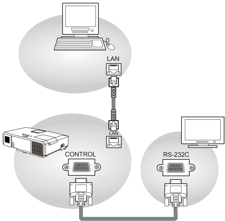
flowchart
graph TD
    A["Computer"] --> B["LAN"]
    B --> C["Printer"]
    C --> D["LAN"]
    D --> E["Controller"]
    E --> F["RS-232C"]
Communication settings
For communication setting, use the OPTION - SERVICE - COMMUNICATION menu. (OPTION menu - SERVICE - COMMUNICATION in the Operating Guide)
| Item | Condition |
| BAUD RATE | 4800bps / 9600bps / 19200bps / 38400bps |
| Data length | 8 bit (fixed) |
| PARITY | NONE/ODD/EVEN |
| Start bit | 1 bit (fixed) |
| Stop bit | 1 bit (fixed) |
| Transmission method | HALF-DUPLEX/FULL-DUPLEX |
NOTE • For connecting the projector to your devices, please read the manual for each devices, and connect them correctly with suitable cables.
- Turn off (the power of) both the projector and other devices and unplug, before connecting them.
- For details of Transmission method, refer to 6.4 Transmission method in the Network Guide.
RS-232C Communication / Network command table
| Names | Operation Type | Header | Command Data | |||||||
| CRC | Action | Type | Setting code | |||||||
| Power | Set | Turn off | BE EF | 03 | 06 00 | 2A D3 | 01 00 | 00 60 | 00 00 | |
| Turn on | BE EF | 03 | 06 00 | BA D2 | 01 00 | 00 60 | 01 00 | |||
| Get | BE EF | 03 | 06 00 | 19 D3 | 02 00 | 00 60 | 00 00 | |||
| [Example return]00 00 [Off] 01 00 [On] 02 00[Cool down] | ||||||||||
| Input Source | Set | COMPUTER IN1 | BE EF | 03 | 06 00 | FE D2 | 01 00 | 00 20 | 00 00 | |
| COMPUTER IN2 | BE EF | 03 | 06 00 | 3E D0 | 01 00 | 00 20 | 04 00 | |||
| HDMI | BE EF | 03 | 06 00 | 0E D2 | 01 00 | 00 20 | 03 00 | |||
| COMPONENT | BE EF | 03 | 06 00 | AE D1 | 01 00 | 00 20 | 05 00 | |||
| S-VIDEO | BE EF | 03 | 06 00 | 9E D3 | 01 00 | 00 20 | 02 00 | |||
| VIDEO | BE EF | 03 | 06 00 | 6E D3 | 01 00 | 00 20 | 01 00 | |||
| USB TYPE A | BE EF | 03 | 06 00 | 5E D1 | 01 00 | 00 20 | 06 00 | |||
| LAN | BE EF | 03 | 06 00 | CE D5 | 01 00 | 00 20 | 0B 00 | |||
| USB TYPE B | BE EF | 03 | 06 00 | FE D7 | 01 00 | 00 20 | 0C 00 | |||
| Get | BE EF | 03 | 06 00 | CD D2 | 02 00 | 00 20 | 00 00 | |||
| Error Status | Get | BE EF | 03 | 06 00 | D9 D8 | 02 00 | 20 60 | 00 00 | ||
| [Example return]00 00 [Normal] 01 00 [Cover error] 02 00 [Fan error] 03 00 [Lamp error]04 00 05 00 07 00 08 00[Temp error] [Air flow error] [Cold error] [Filter error] | ||||||||||
| MAGNIFY | Get | BE EF | 03 | 06 00 | 7C D2 | 02 00 | 07 30 | 00 00 | ||
| Increment | BE EF | 03 | 06 00 | 1A D2 | 04 00 | 07 30 | 00 00 | |||
| Decrement | BE EF | 03 | 06 00 | CB D3 | 05 00 | 07 30 | 00 00 | |||
| FREEZE | Set | NORMAL | BE EF | 03 | 06 00 | 83 D2 | 01 00 | 02 30 | 00 00 | |
| FREEZE | BE EF | 03 | 06 00 | 13 D3 | 01 00 | 02 30 | 01 00 | |||
| Get | BE EF | 03 | 06 00 | B0 D2 | 02 00 | 02 30 | 00 00 | |||
| PICTURE MODE | Set | NORMAL | BE EF | 03 | 06 00 | 23 F6 | 01 00 | BA 30 | 00 00 | |
| CINEMA | BE EF | 03 | 06 00 | B3 F7 | 01 00 | BA 30 | 01 00 | |||
| DYNAMIC | BE EF | 03 | 06 00 | E3 F4 | 01 00 | BA 30 | 04 00 | |||
| BOARD(BLACK) | BE EF | 03 | 06 00 | E3 EF | 01 00 | BA 30 | 20 00 | |||
| BOARD(GREEN) | BE EF | 03 | 06 00 | 73 EE | 01 00 | BA 30 | 21 00 | |||
| WHITEBOARD | BE EF | 03 | 06 00 | 83 EE | 01 00 | BA 30 | 22 00 | |||
| Daylight Mode | BE EF | 03 | 06 00 | 23 E2 | 01 00 | BA 30 | 30 00 | |||
| Get | BE EF | 03 | 06 00 | 10 F6 | 02 00 | BA 30 | 00 00 | |||
| [Example return]00 00 [Normal] 01 00 [Cinema] 04 00 [Dynamic] 10 00 [Custom]20 00 21 00 22 00 40 00[BOARD(BLACK)][BOARD(GREEN)][WHITEBOARD][DAY TIME] | ||||||||||
| BRIGHTNESS | Get | BE EF | 03 | 06 00 | 89 D2 | 02 00 | 03 20 | 00 00 | ||
| Increment | BE EF | 03 | 06 00 | EF D2 | 04 00 | 03 20 | 00 00 | |||
| Decrement | BE EF | 03 | 06 00 | 3E D3 | 05 00 | 03 20 | 00 00 | |||
| BRIGHTNESS Reset | Execute | BE EF | 03 | 06 00 | 58 D3 | 06 00 | 00 70 | 00 00 | ||
(continued on next page)
RS-232C Communication / Network command table (continued)
| Names | Operation Type | Header | Command Data | |||||||
| CRC | Action | Type | Setting code | |||||||
| CONTRAST | Get | BE EF | 03 | 06 00 | FD D3 | 02 00 | 04 20 | 00 00 | ||
| Increment | BE EF | 03 | 06 00 | 9B D3 | 04 00 | 04 20 | 00 00 | |||
| Decrement | BE EF | 03 | 06 00 | 4A D2 | 05 00 | 04 20 | 00 00 | |||
| CONTRAST Reset | Execute | BE EF | 03 | 06 00 | A4 D2 | 06 00 | 01 70 | 00 00 | ||
| GAMMA | Set | 1 DEFAULT | BE EF | 03 | 06 00 | 07 E9 | 01 00 | A1 30 | 20 00 | |
| 1 CUSTOM | BE EF | 03 | 06 00 | 07 FD | 01 00 | A1 30 | 10 00 | |||
| 2 DEFAULT | BE EF | 03 | 06 00 | 97 E8 | 01 00 | A1 30 | 21 00 | |||
| 2 CUSTOM | BE EF | 03 | 06 00 | 97 FC | 01 00 | A1 30 | 11 00 | |||
| 3 DEFAULT | BE EF | 03 | 06 00 | 67 E8 | 01 00 | A1 30 | 22 00 | |||
| 3 CUSTOM | BE EF | 03 | 06 00 | 67 FC | 01 00 | A1 30 | 12 00 | |||
| 4 DEFAULT | BE EF | 03 | 06 00 | F7 E9 | 01 00 | A1 30 | 23 00 | |||
| 4 CUSTOM | BE EF | 03 | 06 00 | F7 FD | 01 00 | A1 30 | 13 00 | |||
| 5 DEFAULT | BE EF | 03 | 06 00 | C7 EB | 01 00 | A1 30 | 24 00 | |||
| 5 CUSTOM | BE EF | 03 | 06 00 | C7 FF | 01 00 | A1 30 | 14 00 | |||
| 6 DEFAULT | BE EF | 03 | 06 00 | 57 EA | 01 00 | A1 30 | 25 00 | |||
| 6 CUSTOM | BE EF | 03 | 06 00 | 57 FE | 01 00 | A1 30 | 15 00 | |||
| Get | BE EF | 03 | 06 00 | F4 F0 | 02 00 | A1 30 | 00 00 | |||
| User Gamma Pattern | Set | Off | BE EF | 03 | 06 00 | FB FA | 01 00 | 80 30 | 00 00 | |
| 9 steps gray scale | BE EF | 03 | 06 00 | 6B FB | 01 00 | 80 30 | 01 00 | |||
| 15 steps gray scale | BE EF | 03 | 06 00 | 9B FB | 01 00 | 80 30 | 02 00 | |||
| Ramp | BE EF | 03 | 06 00 | 0B FA | 01 00 | 80 30 | 03 00 | |||
| Get | BE EF | 03 | 06 00 | C8 FA | 02 00 | 80 30 | 00 00 | |||
| User Gamma Point 1 | Get | BE EF | 03 | 06 00 | 08 FE | 02 00 | 90 30 | 00 00 | ||
| Increment | BE EF | 03 | 06 00 | 6E FE | 04 00 | 90 30 | 00 00 | |||
| Decrement | BE EF | 03 | 06 00 | BF FF | 05 00 | 90 30 | 00 00 | |||
| User Gamma Point 1 Reset | Execute | BE EF | 03 | 06 00 | 58 C2 | 06 00 | 50 70 | 00 00 | ||
| User Gamma Point 2 | Get | BE EF | 03 | 06 00 | F4 FF | 02 00 | 91 30 | 00 00 | ||
| Increment | BE EF | 03 | 06 00 | 92 FF | 04 00 | 91 30 | 00 00 | |||
| Decrement | BE EF | 03 | 06 00 | 43 FE | 05 00 | 91 30 | 00 00 | |||
| User Gamma Point 2 Reset | Execute | BE EF | 03 | 06 00 | A4 C3 | 06 00 | 51 70 | 00 00 | ||
| User Gamma Point 3 | Get | BE EF | 03 | 06 00 | B0 FF | 02 00 | 92 30 | 00 00 | ||
| Increment | BE EF | 03 | 06 00 | D6 FF | 04 00 | 92 30 | 00 00 | |||
| Decrement | BE EF | 03 | 06 00 | 07 FE | 05 00 | 92 30 | 00 00 | |||
| User Gamma Point 3 Reset | Execute | BE EF | 03 | 06 00 | E0 C3 | 06 00 | 52 70 | 00 00 | ||
| User Gamma Point 4 | Get | BE EF | 03 | 06 00 | 4C FE | 02 00 | 93 30 | 00 00 | ||
| Increment | BE EF | 03 | 06 00 | 2A FE | 04 00 | 93 30 | 00 00 | |||
| Decrement | BE EF | 03 | 06 00 | FB FF | 05 00 | 93 30 | 00 00 | |||
| User Gamma Point 4 Reset | Execute | BE EF | 03 | 06 00 | 1C C2 | 06 00 | 53 70 | 00 00 | ||
| User Gamma Point 5 | Get | BE EF | 03 | 06 00 | 38 FF | 02 00 | 94 30 | 00 00 | ||
| Increment | BE EF | 03 | 06 00 | 5E FF | 04 00 | 94 30 | 00 00 | |||
| Decrement | BE EF | 03 | 06 00 | 8F FE | 05 00 | 94 30 | 00 00 | |||
| User Gamma Point 5 Reset | Execute | BE EF | 03 | 06 00 | 68 C3 | 06 00 | 54 70 | 00 00 | ||
RS-232C Communication / Network command table (continued)
| Names | Operation Type | Header | Command Data | ||||||
| CRC | Action | Type Setting code | |||||||
| User Gamma Point 6 | Get | BE EF | 03 | 06 00 | C4 FE | 02 00 | 95 30 | 00 00 | |
| Increment | BE EF | 03 | 06 00 | A2 FE | 04 00 | 95 30 | 00 00 | ||
| Decrement | BE EF | 03 | 06 00 | 73 FF | 05 00 | 95 30 | 00 00 | ||
| User Gamma Point 6 Reset | Execute | BE EF | 03 | 06 00 | 94 C2 | 06 00 | 55 70 | 00 00 | |
| User Gamma Point 7 | Get | BE EF | 03 | 06 00 | 80 FE | 02 00 | 96 30 | 00 00 | |
| Increment | BE EF | 03 | 06 00 | E6 FE | 04 00 | 96 30 | 00 00 | ||
| Decrement | BE EF | 03 | 06 00 | 37 FF | 05 00 | 96 30 | 00 00 | ||
| User Gamma Point 7 Reset | Execute | BE EF | 03 | 06 00 | D0 C2 | 06 00 | 56 70 | 00 00 | |
| User Gamma Point 8 | Get | BE EF | 03 | 06 00 | 7C FF | 02 00 | 97 30 | 00 00 | |
| Increment | BE EF | 03 | 06 00 | 1A FF | 04 00 | 97 30 | 00 00 | ||
| Decrement | BE EF | 03 | 06 00 | CB FE | 05 00 | 97 30 | 00 00 | ||
| User Gamma Point 8 Reset | Execute | BE EF | 03 | 06 00 | 2C C3 | 06 00 | 57 70 | 00 00 | |
| COLOR TEMP | Set | 1 HIGH | BE EF | 03 | 06 00 | 0B F5 | 01 00 | B0 30 | 03 00 |
| 1 CUSTOM | BE EF | 03 | 06 00 | CB F8 | 01 00 | B0 30 | 13 00 | ||
| 2 MID | BE EF | 03 | 06 00 | 9B F4 | 01 00 | B0 30 | 02 00 | ||
| 2 CUSTOM | BE EF | 03 | 06 00 | 5B F9 | 01 00 | B0 30 | 12 00 | ||
| 3 LOW | BE EF | 03 | 06 00 | 6B F4 | 01 00 | B0 30 | 01 00 | ||
| 3 CUSTOM | BE EF | 03 | 06 00 | AB F9 | 01 00 | B0 30 | 11 00 | ||
| 4 Hi-BRIGHT-1 | BE EF | 03 | 06 00 | 3B F2 | 01 00 | B0 30 | 08 00 | ||
| 4 CUSTOM | BE EF | 03 | 06 00 | FB FF | 01 00 | B0 30 | 18 00 | ||
| 5 Hi-BRIGHT-2 | BE EF | 03 | 06 00 | AB F3 | 01 00 | B0 30 | 09 00 | ||
| 5 CUSTOM | BE EF | 03 | 06 00 | 6B FE | 01 00 | B0 30 | 19 00 | ||
| 6 Hi-BRIGHT-3 | BE EF | 03 | 06 00 | 5B F3 | 01 00 | B0 30 | 0A 00 | ||
| 6 CUSTOM | BE EF | 03 | 06 00 | 9B FE | 01 00 | B0 30 | 1A 00 | ||
| Get | BE EF | 03 | 06 00 | C8 F5 | 02 00 | B0 30 | 00 00 | ||
| COLOR TEMP GAIN R | Get | BE EF | 03 | 06 00 | 34 F4 | 02 00 | B1 30 | 00 00 | |
| Increment | BE EF | 03 | 06 00 | 52 F4 | 04 00 | B1 30 | 00 00 | ||
| Decrement | BE EF | 03 | 06 00 | 83 F5 | 05 00 | B1 30 | 00 00 | ||
| COLOR TEMP GAIN R Reset | Execute | BE EF | 03 | 06 00 | 10 C6 | 06 00 | 46 70 | 00 00 | |
| COLOR TEMP GAIN G | Get | BE EF | 03 | 06 00 | 70 F4 | 02 00 | B2 30 | 00 00 | |
| Increment | BE EF | 03 | 06 00 | 16 F4 | 04 00 | B2 30 | 00 00 | ||
| Decrement | BE EF | 03 | 06 00 | C7 F5 | 05 00 | B2 30 | 00 00 | ||
| COLOR TEMP GAIN G Reset | Execute | BE EF | 03 | 06 00 | EC C7 | 06 00 | 47 70 | 00 00 | |
| COLOR TEMP GAIN B | Get | BE EF | 03 | 06 00 | 8C F5 | 02 00 | B3 30 | 00 00 | |
| Increment | BE EF | 03 | 06 00 | EA F5 | 04 00 | B3 30 | 00 00 | ||
| Decrement | BE EF | 03 | 06 00 | 3B F4 | 05 00 | B3 30 | 00 00 | ||
| COLOR TEMP GAIN B Reset | Execute | BE EF | 03 | 06 00 | F8 C4 | 06 00 | 48 70 | 00 00 | |
| COLOR TEMP OFFSET R | Get | BE EF | 03 | 06 00 | 04 F5 | 02 00 | B5 30 | 00 00 | |
| Increment | BE EF | 03 | 06 00 | 62 F5 | 04 00 | B5 30 | 00 00 | ||
| Decrement | BE EF | 03 | 06 00 | B3 F4 | 05 00 | B5 30 | 00 00 | ||
| COLOR TEMP OFFSET R Reset | Execute | BE EF | 03 | 06 00 | 40 C5 | 06 00 | 4A 70 | 00 00 | |
RS-232C Communication / Network command table (continued)
| Names | Operation Type | Header | Command Data | |||||||
| CRC | Action | Type | Setting code | |||||||
| COLOR TEMP OFFSET G | Get | BE EF | 03 | 06 00 | 40 F5 | 02 00 | B6 30 | 00 00 | ||
| Increment | BE EF | 03 | 06 00 | 26 F5 | 04 00 | B6 30 | 00 00 | |||
| Decrement | BE EF | 03 | 06 00 | F7 F4 | 05 00 | B6 30 | 00 00 | |||
| COLOR TEMP OFFSET G Reset | Execute | BE EF | 03 | 06 00 | BC C4 | 06 00 | 4B 70 | 00 00 | ||
| COLOR TEMP OFFSET B | Get | BE EF | 03 | 06 00 | BC F4 | 02 00 | B7 30 | 00 00 | ||
| Increment | BE EF | 03 | 06 00 | DA F4 | 04 00 | B7 30 | 00 00 | |||
| Decrement | BE EF | 03 | 06 00 | 0B F5 | 05 00 | B7 30 | 00 00 | |||
| COLOR TEMP OFFSET B Reset | Execute | BE EF | 03 | 06 00 | C8 C5 | 06 00 | 4C 70 | 00 00 | ||
| COLOR | Get | BE EF | 03 | 06 00 | B5 72 | 02 00 | 02 22 | 00 00 | ||
| Increment | BE EF | 03 | 06 00 | D3 72 | 04 00 | 02 22 | 00 00 | |||
| Decrement | BE EF | 03 | 06 00 | 02 73 | 05 00 | 02 22 | 00 00 | |||
| COLOR Reset | Execute | BE EF | 03 | 06 00 | 80 D0 | 06 00 | 0A 70 | 00 00 | ||
| TINT | Get | BE EF | 03 | 06 00 | 49 73 | 02 00 | 03 22 | 00 00 | ||
| Increment | BE EF | 03 | 06 00 | 2F 73 | 04 00 | 03 22 | 00 00 | |||
| Decrement | BE EF | 03 | 06 00 | FE 72 | 05 00 | 03 22 | 00 00 | |||
| TINT Reset | Execute | BE EF | 03 | 06 00 | 7C D1 | 06 00 | 0B 70 | 00 00 | ||
| SHARPNESS | Get | BE EF | 03 | 06 00 | F1 72 | 02 00 | 01 22 | 00 00 | ||
| Increment | BE EF | 03 | 06 00 | 97 72 | 04 00 | 01 22 | 00 00 | |||
| Decrement | BE EF | 03 | 06 00 | 46 73 | 05 00 | 01 22 | 00 00 | |||
| SHARPNESS Reset | Execute | BE EF | 03 | 06 00 | C4 D0 | 06 00 | 09 70 | 00 00 | ||
| ACTIVE IRIS | Set | OFF | BE EF | 03 | 06 00 | 0B 22 | 01 00 | 04 33 | 00 00 | |
| THEATER | BE EF | 03 | 06 00 | CB 2F | 01 00 | 04 33 | 10 00 | |||
| PRESENTATION | BE EF | 03 | 06 00 | 5B 2E | 01 00 | 04 33 | 11 00 | |||
| Get | BE EF | 03 | 06 00 | 38 22 | 02 00 | 04 33 | 00 00 | |||
| MY MEMORY Load | Set | 1 | BE EF | 03 | 06 00 | 0E D7 | 01 00 | 14 20 | 00 00 | |
| 2 | BE EF | 03 | 06 00 | 9E D6 | 01 00 | 14 20 | 01 00 | |||
| 3 | BE EF | 03 | 06 00 | 6E D6 | 01 00 | 14 20 | 02 00 | |||
| 4 | BE EF | 03 | 06 00 | FE D7 | 01 00 | 14 20 | 03 00 | |||
| MY MEMORY Save | Set | 1 | BE EF | 03 | 06 00 | F2 D6 | 01 00 | 15 20 | 00 00 | |
| 2 | BE EF | 03 | 06 00 | 62 D7 | 01 00 | 15 20 | 01 00 | |||
| 3 | BE EF | 03 | 06 00 | 92 D7 | 01 00 | 15 20 | 02 00 | |||
| 4 | BE EF | 03 | 06 00 | 02 D6 | 01 00 | 15 20 | 03 00 | |||
| ASPECT | Set | 4:3 | BE EF | 03 | 06 00 | 9E D0 | 01 00 | 08 20 | 00 00 | |
| 16:9 | BE EF | 03 | 06 00 | 0E D1 | 01 00 | 08 20 | 01 00 | |||
| 16:10 | BE EF | 03 | 06 00 | 3E D6 | 01 00 | 08 20 | 0A 00 | |||
| 14:9 | BE EF | 03 | 06 00 | CE D6 | 01 00 | 08 20 | 09 00 | |||
| NORMAL | BE EF | 03 | 06 00 | 5E DD | 01 00 | 08 20 | 10 00 | |||
| Get | BE EF | 03 | 06 00 | AD D0 | 02 00 | 08 20 | 00 00 | |||
| OVER SCAN | Get | BE EF | 03 | 06 00 | 91 70 | 02 00 | 09 22 | 00 00 | ||
| Increment | BE EF | 03 | 06 00 | F7 70 | 04 00 | 09 22 | 00 00 | |||
| Decrement | BE EF | 03 | 06 00 | 26 71 | 05 00 | 09 22 | 00 00 | |||
| Names | Operation Type | Header | Command Data | |||||||
| CRC | Action | Type Setting code | ||||||||
| OVER SCAN Reset | Execute | BE EF | 03 | 06 00 | EC D9 | 06 00 | 27 70 | 00 00 | ||
| V POSITION | Get | BE EF | 03 | 06 00 | 0D 83 | 02 00 | 00 21 | 00 00 | ||
| Increment | BE EF | 03 | 06 00 | 6B 83 | 04 00 | 00 21 | 00 00 | |||
| Decrement | BE EF | 03 | 06 00 | BA 82 | 05 00 | 00 21 | 00 00 | |||
| V POSITION Reset | Execute | BE EF | 03 | 06 00 | E0 D2 | 06 00 | 02 70 | 00 00 | ||
| H POSITION | Get | BE EF | 03 | 06 00 | F1 82 | 02 00 | 01 21 | 00 00 | ||
| Increment | BE EF | 03 | 06 00 | 97 82 | 04 00 | 01 21 | 00 00 | |||
| Decrement | BE EF | 03 | 06 00 | 46 83 | 05 00 | 01 21 | 00 00 | |||
| H POSITION Reset | Execute | BE EF | 03 | 06 00 | 1C D3 | 06 00 | 03 70 | 00 00 | ||
| H PHASE | Get | BE EF | 03 | 06 00 | 49 83 | 02 00 | 03 21 | 00 00 | ||
| Increment | BE EF | 03 | 06 00 | 2F 83 | 04 00 | 03 21 | 00 00 | |||
| Decrement | BE EF | 03 | 06 00 | FE 82 | 05 00 | 03 21 | 00 00 | |||
| H SIZE | Get | BE EF | 03 | 06 00 | B5 82 | 02 00 | 02 21 | 00 00 | ||
| Increment | BE EF | 03 | 06 00 | D3 82 | 04 00 | 02 21 | 00 00 | |||
| Decrement | BE EF | 03 | 06 00 | 02 83 | 05 00 | 02 21 | 00 00 | |||
| H SIZE Reset | Execute | BE EF | 03 | 06 00 | 68 D2 | 06 00 | 04 70 | 00 00 | ||
| AUTO ADJUST EXECUTE | Execute | BE EF | 03 | 06 00 | 91 D0 | 06 00 | 0A 20 | 00 00 | ||
| PROGRESSIVE | Set | OFF | BE EF | 03 | 06 00 | 4A 72 | 01 00 | 07 22 | 00 00 | |
| TV | BE EF | 03 | 06 00 | DA 73 | 01 00 | 07 22 | 01 00 | |||
| FILM | BE EF | 03 | 06 00 | 2A 73 | 01 00 | 07 22 | 02 00 | |||
| Get | BE EF | 03 | 06 00 | 79 72 | 02 00 | 07 22 | 00 00 | |||
| VIDEO NR | Set | LOW | BE EF | 03 | 06 00 | 26 72 | 01 00 | 06 22 | 01 00 | |
| MID | BE EF | 03 | 06 00 | D6 72 | 01 00 | 06 22 | 02 00 | |||
| HIGH | BE EF | 03 | 06 00 | 46 73 | 01 00 | 06 22 | 03 00 | |||
| Get | BE EF | 03 | 06 00 | 85 73 | 02 00 | 06 22 | 00 00 | |||
| COLOR SPACE | Set | AUTO | BE EF | 03 | 06 00 | OE 72 | 01 00 | 04 22 | 00 00 | |
| RGB | BE EF | 03 | 06 00 | 9E 73 | 01 00 | 04 22 | 01 00 | |||
| SMPTE240 | BE EF | 03 | 06 00 | 6E 73 | 01 00 | 04 22 | 02 00 | |||
| REC709 | BE EF | 03 | 06 00 | FE 72 | 01 00 | 04 22 | 03 00 | |||
| REC601 | BE EF | 03 | 06 00 | CE 70 | 01 00 | 04 22 | 04 00 | |||
| Get | BE EF | 03 | 06 00 | 3D 72 | 02 00 | 04 22 | 00 00 | |||
| COMPONENT | Set | COMPONENT | BE EF | 03 | 06 00 | 4A D7 | 01 00 | 17 20 | 00 00 | |
| SCART RGB | BE EF | 03 | 06 00 | DA D6 | 01 00 | 17 20 | 01 00 | |||
| Get | BE EF | 03 | 06 00 | 79 D7 | 02 00 | 17 20 | 00 00 | |||
| S-VIDEO FORMAT | Set | AUTO | BE EF | 03 | 06 00 | E6 70 | 01 00 | 12 22 | 0A 00 | |
| NTSC | BE EF | 03 | 06 00 | 86 74 | 01 00 | 12 22 | 04 00 | |||
| PAL | BE EF | 03 | 06 00 | 16 75 | 01 00 | 12 22 | 05 00 | |||
| SECAM | BE EF | 03 | 06 00 | 16 70 | 01 00 | 12 22 | 09 00 | |||
| NTSC4.43 | BE EF | 03 | 06 00 | 26 77 | 01 00 | 12 22 | 02 00 | |||
| M-PAL | BE EF | 03 | 06 00 | 86 71 | 01 00 | 12 22 | 08 00 | |||
| N-PAL | BE EF | 03 | 06 00 | 76 74 | 01 00 | 12 22 | 07 00 | |||
| Get | BE EF | 03 | 06 00 | 75 76 | 02 00 | 12 22 | 00 00 | |||
| C-VIDEO FORMAT | Set | AUTO | BE EF | 03 | 06 00 | A2 70 | 01 00 | 11 22 | 0A 00 | |
| NTSC | BE EF | 03 | 06 00 | C2 74 | 01 00 | 11 22 | 04 00 | |||
| PAL | BE EF | 03 | 06 00 | 52 75 | 01 00 | 11 22 | 05 00 | |||
| SECAM | BE EF | 03 | 06 00 | 52 70 | 01 00 | 11 22 | 09 00 | |||
| NTSC4.43 | BE EF | 03 | 06 00 | 62 77 | 01 00 | 11 22 | 02 00 | |||
| M-PAL | BE EF | 03 | 06 00 | C2 71 | 01 00 | 11 22 | 08 00 | |||
| N-PAL | BE EF | 03 | 06 00 | 32 74 | 01 00 | 11 22 | 07 00 | |||
| Get | BE EF | 03 | 06 00 | 31 76 | 02 00 | 11 22 | 00 00 | |||
| HDMI FORMAT | Set | AUTO | BE EF | 03 | 06 00 | BA 77 | 01 00 | 13 22 | 00 00 | |
| VIDEO | BE EF | 03 | 06 00 | 2A 76 | 01 00 | 13 22 | 01 00 | |||
| COMPUTER | BE EF | 03 | 06 00 | DA 76 | 01 00 | 13 22 | 02 00 | |||
| Get | BE EF | 03 | 06 00 | 89 77 | 02 00 | 13 22 | 00 00 | |||
| HDMI RANGE | Set | AUTO | BE EF | 03 | 06 00 | 86 D8 | 01 00 | 22 20 | 00 00 | |
| NORMAL | BE EF | 03 | 06 00 | 16 D9 | 01 00 | 22 20 | 01 00 | |||
| ENHANCED | BE EF | 03 | 06 00 | E6 D9 | 01 00 | 22 20 | 02 00 | |||
| Get | BE EF | 03 | 06 00 | B5 D8 | 02 00 | 22 20 | 00 00 | |||
| COMPUTER IN1 | Set | AUTO | BE EF | 03 | 06 00 | CE D6 | 01 00 | 10 20 | 03 00 | |
| SYNC ON G OFF | BE EF | 03 | 06 00 | 5E D7 | 01 00 | 10 20 | 02 00 | |||
| Get | BE EF | 03 | 06 00 | 0D D6 | 02 00 | 10 20 | 00 00 | |||
| COMPUTER IN2 | Set | AUTO | BE EF | 03 | 06 00 | 32 D7 | 01 00 | 11 20 | 03 00 | |
| SYNC ON G OFF | BE EF | 03 | 06 00 | A2 D6 | 01 00 | 11 20 | 02 00 | |||
| Get | BE EF | 03 | 06 00 | F1 D7 | 02 00 | 11 20 | 00 00 | |||
| FRAME LOCK - COMPUTER IN1 | Set | OFF | BE EF | 03 | 06 00 | 3B C2 | 01 00 | 50 30 | 00 00 | |
| ON | BE EF | 03 | 06 00 | AB C3 | 01 00 | 50 30 | 01 00 | |||
| Get | BE EF | 03 | 06 00 | 08 C2 | 02 00 | 50 30 | 00 00 | |||
| FRAME LOCK - COMPUTER IN2 | Set | OFF | BE EF | 03 | 06 00 | 0B C3 | 01 00 | 54 30 | 00 00 | |
| ON | BE EF | 03 | 06 00 | 9B C2 | 01 00 | 54 30 | 01 00 | |||
| Get | BE EF | 03 | 06 00 | 38 C3 | 02 00 | 54 30 | 00 00 | |||
| FRAME LOCK - HDMI | Set | OFF | BE EF | 03 | 06 00 | 7F C2 | 01 00 | 53 30 | 00 00 | |
| ON | BE EF | 03 | 06 00 | EF C3 | 01 00 | 53 30 | 01 00 | |||
| Get | BE EF | 03 | 06 00 | 4C C2 | 02 00 | 53 30 | 00 00 | |||
| AUTO KEYSTONE V EXECUTE | Execute | BE EF | 03 | 06 00 | E5 D1 | 06 00 | 0D 20 | 00 00 | ||
| KEYSTONE V | Get | BE EF | 03 | 06 00 | B9 D3 | 02 00 | 07 20 | 00 00 | ||
| Increment | BE EF | 03 | 06 00 | DF D3 | 04 00 | 07 20 | 00 00 | |||
| Decrement | BE EF | 03 | 06 00 | OE D2 | 05 00 | 07 20 | 00 00 | |||
| KEYSTONE V Reset | Execute | BE EF | 03 | 06 00 | 08 D0 | 06 00 | 0C 70 | 00 00 | ||
| KEYSTONE H | Get | BE EF | 03 | 06 00 | E9 D0 | 02 00 | 0B 20 | 00 00 | ||
| Increment | BE EF | 03 | 06 00 | 8F D0 | 04 00 | 0B 20 | 00 00 | |||
| Decrement | BE EF | 03 | 06 00 | 5E D1 | 05 00 | 0B 20 | 00 00 | |||
| KEYSTONE H Reset | Execute | BE EF | 03 | 06 00 | 98 D8 | 06 00 | 20 70 | 00 00 | ||
| PERFECT FIT | Set | Disable | BE EF | 03 | 06 00 | FE 88 | 01 00 | 20 21 | 00 00 | |
| Enable | BE EF | 03 | 06 00 | 6E 89 | 01 00 | 20 21 | 01 00 | |||
| Get | BE EF | 03 | 06 00 | CD 88 | 02 00 | 20 21 | 00 00 | |||
| PERFECT FIT Left Top -H | Get | BE EF | 03 | 06 00 | 31 89 | 02 00 | 21 21 | 00 00 | ||
| Increment | BE EF | 03 | 06 00 | 57 89 | 04 00 | 21 21 | 00 00 | |||
| Decrement | BE EF | 03 | 06 00 | 86 88 | 05 00 | 21 21 | 00 00 | |||
(continued on next page)
RS-232C Communication / Network command table (continued)
| Names | Operation Type | Header | CRC | Command Data | ||||||
| Action | Type | Setting code | ||||||||
| PERFECT FIT Left Top -V | Get | BE EF | 03 | 06 00 | 75 89 | 02 00 | 22 21 | 00 00 | ||
| Increment | BE EF | 03 | 06 00 | 13 89 | 04 00 | 22 21 | 00 00 | |||
| Decrement | BE EF | 03 | 06 00 | C2 88 | 05 00 | 22 21 | 00 00 | |||
| PERFECT FIT Right Top -H | Get | BE EF | 03 | 06 00 | 89 88 | 02 00 | 23 21 | 00 00 | ||
| Increment | BE EF | 03 | 06 00 | EF 88 | 04 00 | 23 21 | 00 00 | |||
| Decrement | BE EF | 03 | 06 00 | 3E 89 | 05 00 | 23 21 | 00 00 | |||
| PERFECT FIT Right Top -V | Get | BE EF | 03 | 06 00 | FD 89 | 02 00 | 24 21 | 00 00 | ||
| Increment | BE EF | 03 | 06 00 | 9B 89 | 04 00 | 24 21 | 00 00 | |||
| Decrement | BE EF | 03 | 06 00 | 4A 88 | 05 00 | 24 21 | 00 00 | |||
| PERFECT FIT Left Bottom -H | Get | BE EF | 03 | 06 00 | 01 88 | 02 00 | 25 21 | 00 00 | ||
| Increment | BE EF | 03 | 06 00 | 67 88 | 04 00 | 25 21 | 00 00 | |||
| Decrement | BE EF | 03 | 06 00 | B6 89 | 05 00 | 25 21 | 00 00 | |||
| PERFECT FIT Left Bottom -V | Get | BE EF | 03 | 06 00 | 45 88 | 02 00 | 26 21 | 00 00 | ||
| Increment | BE EF | 03 | 06 00 | 23 88 | 04 00 | 26 21 | 00 00 | |||
| Decrement | BE EF | 03 | 06 00 | F2 89 | 05 00 | 26 21 | 00 00 | |||
| PERFECT FIT Right Bottom -H | Get | BE EF | 03 | 06 00 | B9 89 | 02 00 | 27 21 | 00 00 | ||
| Increment | BE EF | 03 | 06 00 | DF 89 | 04 00 | 27 21 | 00 00 | |||
| Decrement | BE EF | 03 | 06 00 | OE 88 | 05 00 | 27 21 | 00 00 | |||
| PERFECT FIT Right Bottom -V | Get | BE EF | 03 | 06 00 | AD 8A | 02 00 | 28 21 | 00 00 | ||
| Increment | BE EF | 03 | 06 00 | CB 8A | 04 00 | 28 21 | 00 00 | |||
| Decrement | BE EF | 03 | 06 00 | 1A 8B | 05 00 | 28 21 | 00 00 | |||
| PERFECT FIT All Corners Reset | Execute | BE EF | 03 | 06 00 | D5 8A | 06 00 | 29 21 | 00 00 | ||
| PERFECT FIT Left Side Distortion | Get | BE EF | 03 | 06 00 | 31 97 | 02 00 | 41 21 | 00 00 | ||
| Increment | BE EF | 03 | 06 00 | 57 97 | 04 00 | 41 21 | 00 00 | |||
| Decrement | BE EF | 03 | 06 00 | 86 96 | 05 00 | 41 21 | 00 00 | |||
| PERFECT FIT Right Side Distortion | Get | BE EF | 03 | 06 00 | 75 97 | 02 00 | 42 21 | 00 00 | ||
| Increment | BE EF | 03 | 06 00 | 13 97 | 04 00 | 42 21 | 00 00 | |||
| Decrement | BE EF | 03 | 06 00 | C2 96 | 05 00 | 42 21 | 00 00 | |||
| PERFECT FIT Distortion Position V | Get | BE EF | 03 | 06 00 | 89 96 | 02 00 | 43 21 | 00 00 | ||
| Increment | BE EF | 03 | 06 00 | EF 96 | 04 00 | 43 21 | 00 00 | |||
| Decrement | BE EF | 03 | 06 00 | 3E 97 | 05 00 | 43 21 | 00 00 | |||
| PERFECT FIT Top Side Distortion | Get | BE EF | 03 | 06 00 | FD 97 | 02 00 | 44 21 | 00 00 | ||
| Increment | BE EF | 03 | 06 00 | 9B 97 | 04 00 | 44 21 | 00 00 | |||
| Decrement | BE EF | 03 | 06 00 | 4A 96 | 05 00 | 44 21 | 00 00 | |||
| PERFECT FIT Bottom Side Distortion | Get | BE EF | 03 | 06 00 | 01 96 | 02 00 | 45 21 | 00 00 | ||
| Increment | BE EF | 03 | 06 00 | 67 96 | 04 00 | 45 21 | 00 00 | |||
| Decrement | BE EF | 03 | 06 00 | B6 97 | 05 00 | 45 21 | 00 00 | |||
| PERFECT FIT Distortion Position H | Get | BE EF | 03 | 06 00 | 45 96 | 02 00 | 46 21 | 00 00 | ||
| Increment | BE EF | 03 | 06 00 | 23 96 | 04 00 | 46 21 | 00 00 | |||
| Decrement | BE EF | 03 | 06 00 | F2 97 | 05 00 | 46 21 | 00 00 | |||
| PERFECT FIT All Sides Reset | Execute | BE EF | 03 | 06 00 | 3D 96 | 06 00 | 47 21 | 00 00 | ||
| AUTO ECO MODE | Set | OFF | BE EF | 03 | 06 00 | FB 27 | 01 00 | 10 33 | 00 00 | |
| ON | BE EF | 03 | 06 00 | 6B 26 | 01 00 | 10 33 | 01 00 | |||
| Get | BE EF | 03 | 06 00 | C8 27 | 02 00 | 10 33 | 00 00 | |||
| ECO MODE | Set | NORMAL | BE EF | 03 | 06 00 | 3B 23 | 01 00 | 00 33 | 00 00 | |
| ECO | BE EF | 03 | 06 00 | AB 22 | 01 00 | 00 33 | 01 00 | |||
| Get | BE EF | 03 | 06 00 | 08 23 | 02 00 | 00 33 | 00 00 | |||
| Names | Operation Type | Header | Command Data | |||||||
| CRC | Action | Type Setting code | ||||||||
| MIRROR | Set | NORMAL | BE EF | 03 | 06 00 | C7 D2 | 01 00 | 01 30 | 00 00 | |
| H:INVERT | BE EF | 03 | 06 00 | 57 D3 | 01 00 | 01 30 | 01 00 | |||
| V:INVERT | BE EF | 03 | 06 00 | A7 D3 | 01 00 | 01 30 | 02 00 | |||
| H&V:INVERT | BE EF | 03 | 06 00 | 37 D2 | 01 00 | 01 30 | 03 00 | |||
| Get | BE EF | 03 | 06 00 | F4 D2 | 02 00 | 01 30 | 00 00 | |||
| STANDBY MODE | Set | NORMAL | BE EF | 03 | 06 00 | D6 D2 | 01 00 | 01 60 | 00 00 | |
| SAVING | BE EF | 03 | 06 00 | 46 D3 | 01 00 | 01 60 | 01 00 | |||
| Get | BE EF | 03 | 06 00 | E5 D2 | 02 00 | 01 60 | 00 00 | |||
| MONITOR OUT - COMPUTER IN1 | Set | COMPUTER IN1 | BE EF | 03 | 06 00 | 3E F4 | 01 00 | B0 20 | 00 00 | |
| OFF | BE EF | 03 | 06 00 | CE B5 | 01 00 | B0 20 | FF 00 | |||
| Get | BE EF | 03 | 06 00 | 0D F4 | 02 00 | B0 20 | 00 00 | |||
| MONITOR OUT - COMPUTER IN2 | Set | COMPUTER IN2 | BE EF | 03 | 06 00 | CE F7 | 01 00 | B4 20 | 04 00 | |
| OFF | BE EF | 03 | 06 00 | FE B4 | 01 00 | B4 20 | FF 00 | |||
| Get | BE EF | 03 | 06 00 | 3D F5 | 02 00 | B4 20 | 00 00 | |||
| MONITOR OUT - COMPONENT | Set | COMPUTER IN1 | BE EF | 03 | 06 00 | F2 F4 | 01 00 | B5 20 | 00 00 | |
| COMPUTER IN2 | BE EF | 03 | 06 00 | 32 F6 | 01 00 | B5 20 | 04 00 | |||
| OFF | BE EF | 03 | 06 00 | 02 B5 | 01 00 | B5 20 | FF 00 | |||
| Get | BE EF | 03 | 06 00 | C1 F4 | 02 00 | B5 20 | 00 00 | |||
| MONITOR OUT - S-VIDEO | Set | COMPUTER IN1 | BE EF | 03 | 06 00 | 86 F5 | 01 00 | B2 20 | 00 00 | |
| COMPUTER IN2 | BE EF | 03 | 06 00 | 46 F7 | 01 00 | B2 20 | 04 00 | |||
| OFF | BE EF | 03 | 06 00 | 76 B4 | 01 00 | B2 20 | FF 00 | |||
| Get | BE EF | 03 | 06 00 | B5 F5 | 02 00 | B2 20 | 00 00 | |||
| MONITOR OUT - VIDEO | Set | COMPUTER IN1 | BE EF | 03 | 06 00 | C2 F5 | 01 00 | B1 20 | 00 00 | |
| COMPUTER IN2 | BE EF | 03 | 06 00 | 02 F7 | 01 00 | B1 20 | 04 00 | |||
| OFF | BE EF | 03 | 06 00 | 32 B4 | 01 00 | B1 20 | FF 00 | |||
| Get | BE EF | 03 | 06 00 | F1 F5 | 02 00 | B1 20 | 00 00 | |||
| MONITOR OUT - HDMI | Set | COMPUTER1 | BE EF | 03 | 06 00 | 7A F4 | 01 00 | B3 20 | 00 00 | |
| COMPUTER2 | BE EF | 03 | 06 00 | BA F6 | 01 00 | B3 20 | 04 00 | |||
| OFF | BE EF | 03 | 06 00 | 8A B5 | 01 00 | B3 20 | FF 00 | |||
| Get | BE EF | 03 | 06 00 | 49 F4 | 02 00 | B3 20 | 00 00 | |||
| MONITOR OUT - LAN | Set | COMPUTER1 | BE EF | 03 | 06 00 | 1A F6 | 01 00 | BB 20 | 00 00 | |
| COMPUTER2 | BE EF | 03 | 06 00 | DA F4 | 01 00 | BB 20 | 04 00 | |||
| OFF | BE EF | 03 | 06 00 | EA B7 | 01 00 | BB 20 | FF 00 | |||
| Get | BE EF | 03 | 06 00 | 29 F6 | 02 00 | BB 20 | 00 00 | |||
| MONITOR OUT-USB TYPE A | Set | COMPUTER1 | BE EF | 03 | 06 00 | B6 F4 | 01 00 | B6 20 | 00 00 | |
| COMPUTER2 | BE EF | 03 | 06 00 | 76 F6 | 01 00 | B6 20 | 04 00 | |||
| OFF | BE EF | 03 | 06 00 | 46 B5 | 01 00 | B6 20 | FF 00 | |||
| Get | BE EF | 03 | 06 00 | 85 F4 | 02 00 | B6 20 | 00 00 | |||
| MONITOR OUT - USB TYPE B | Set | COMPUTER1 | BE EF | 03 | 06 00 | 6E F7 | 01 00 | BC 20 | 00 00 | |
| COMPUTER2 | BE EF | 03 | 06 00 | AE F5 | 01 00 | BC 20 | 04 00 | |||
| OFF | BE EF | 03 | 06 00 | 9E B6 | 01 00 | BC 20 | FF 00 | |||
| Get | BE EF | 03 | 06 00 | 5D F7 | 02 00 | BC 20 | 00 00 | |||
| MONITOR OUT - STANDBY | Set | COMPUTER IN1 | BE EF | 03 | 06 00 | 2A F7 | 01 00 | BF 20 | 00 00 | |
| COMPUTER IN2 | BE EF | 03 | 06 00 | EA F5 | 01 00 | BF 20 | 04 00 | |||
| OFF | BE EF | 03 | 06 00 | DA B6 | 01 00 | BF 20 | FF 00 | |||
| Get | BE EF | 03 | 06 00 | 19 F7 | 02 00 | BF 20 | 00 00 | |||
| VOLUME - COMPUTER IN1 | Get | BE EF | 03 | 06 00 | CD CC | 02 00 | 60 20 | 00 00 | ||
| Increment | BE EF | 03 | 06 00 | AB CC | 04 00 | 60 20 | 00 00 | |||
| Decrement | BE EF | 03 | 06 00 | 7A CD | 05 00 | 60 20 | 00 00 | |||
RS-232C Communication / Network command table (continued)
| Names | Operation Type | Header | Command Data | |||||||
| CRC | Action | Type | Setting code | |||||||
| VOLUME - COMPUTER IN2 | Get | BE EF | 03 | 06 00 | FD CD | 02 00 | 64 20 | 00 00 | ||
| Increment | BE EF | 03 | 06 00 | 9B CD | 04 00 | 64 20 | 00 00 | |||
| Decrement | BE EF | 03 | 06 00 | 4A CC | 05 00 | 64 20 | 00 00 | |||
| VOLUME - COMPONENT | Get | BE EF | 03 | 06 00 | 01 CC | 02 00 | 65 20 | 00 00 | ||
| Increment | BE EF | 03 | 06 00 | 67 CC | 04 00 | 65 20 | 00 00 | |||
| Decrement | BE EF | 03 | 06 00 | B6 CD | 05 00 | 65 20 | 00 00 | |||
| VOLUME - S-VIDEO | Get | BE EF | 03 | 06 00 | 75 CD | 02 00 | 62 20 | 00 00 | ||
| Increment | BE EF | 03 | 06 00 | 13 CD | 04 00 | 62 20 | 00 00 | |||
| Decrement | BE EF | 03 | 06 00 | C2 CC | 05 00 | 62 20 | 00 00 | |||
| VOLUME - VIDEO | Get | BE EF | 03 | 06 00 | 31 CD | 02 00 | 61 20 | 00 00 | ||
| Increment | BE EF | 03 | 06 00 | 57 CD | 04 00 | 61 20 | 00 00 | |||
| Decrement | BE EF | 03 | 06 00 | 86 CC | 05 00 | 61 20 | 00 00 | |||
| VOLUME - HDMI | Get | BE EF | 03 | 06 00 | 89 CC | 02 00 | 63 20 | 00 00 | ||
| Increment | BE EF | 03 | 06 00 | EF CC | 04 00 | 63 20 | 00 00 | |||
| Decrement | BE EF | 03 | 06 00 | 3E CD | 05 00 | 63 20 | 00 00 | |||
| VOLUME - LAN | Get | BE EF | 03 | 06 00 | E9 CE | 02 00 | 6B 20 | 00 00 | ||
| Increment | BE EF | 03 | 06 00 | 8F CE | 04 00 | 6B 20 | 00 00 | |||
| Decrement | BE EF | 03 | 06 00 | 5E CF | 05 00 | 6B 20 | 00 00 | |||
| VOLUME - USB TYPE A | Get | BE EF | 03 | 06 00 | 45 CC | 02 00 | 66 20 | 00 00 | ||
| Increment | BE EF | 03 | 06 00 | 23 CC | 04 00 | 66 20 | 00 00 | |||
| Decrement | BE EF | 03 | 06 00 | F2 CD | 05 00 | 66 20 | 00 00 | |||
| VOLUME - USB TYPE B | Get | BE EF | 03 | 06 00 | 9D CF | 02 00 | 6C 20 | 00 00 | ||
| Increment | BE EF | 03 | 06 00 | FB CF | 04 00 | 6C 20 | 00 00 | |||
| Decrement | BE EF | 03 | 06 00 | 2A CE | 05 00 | 6C 20 | 00 00 | |||
| VOLUME - STANDBY | Get | BE EF | 03 | 06 00 | D9 CF | 02 00 | 6F 20 | 00 00 | ||
| Increment | BE EF | 03 | 06 00 | BF CF | 04 00 | 6F 20 | 00 00 | |||
| Decrement | BE EF | 03 | 06 00 | 6E CE | 05 00 | 6F 20 | 00 00 | |||
| MUTE | Set | OFF | BE EF | 03 | 06 00 | 46 D3 | 01 00 | 02 20 | 00 00 | |
| ON | BE EF | 03 | 06 00 | D6 D2 | 01 00 | 02 20 | 01 00 | |||
| Get | BE EF | 03 | 06 00 | 75 D3 | 02 00 | 02 20 | 00 00 | |||
| SPEAKER | Set | ON | BE EF | 03 | 06 00 | FE D4 | 01 00 | 1C 20 | 01 00 | |
| OFF | BE EF | 03 | 06 00 | 6E D5 | 01 00 | 1C 20 | 00 00 | |||
| Get | BE EF | 03 | 06 00 | 5D D5 | 02 00 | 1C 20 | 00 00 | |||
| AUDIO SOURCE - COMPUTER IN1 | Set | AUDIO IN1 | BE EF | 03 | 06 00 | 6E DC | 01 00 | 30 20 | 01 00 | |
| AUDIO IN2 | BE EF | 03 | 06 00 | 9E DC | 01 00 | 30 20 | 02 00 | |||
| AUDIO IN3 | BE EF | 03 | 06 00 | OE DD | 01 00 | 30 20 | 03 00 | |||
| OFF | BE EF | 03 | 06 00 | FE DD | 01 00 | 30 20 | 00 00 | |||
| Get | BE EF | 03 | 06 00 | CD DD | 02 00 | 30 20 | 00 00 | |||
| AUDIO SOURCE - COMPUTER IN2 | Set | AUDIO IN1 | BE EF | 03 | 06 00 | 5E DD | 01 00 | 34 20 | 01 00 | |
| AUDIO IN2 | BE EF | 03 | 06 00 | AE DD | 01 00 | 34 20 | 02 00 | |||
| AUDIO IN3 | BE EF | 03 | 06 00 | 3E DC | 01 00 | 34 20 | 03 00 | |||
| OFF | BE EF | 03 | 06 00 | CE DC | 01 00 | 34 20 | 00 00 | |||
| Get | BE EF | 03 | 06 00 | FD DC | 02 00 | 34 20 | 00 00 | |||
| AUDIO SOURCE LAN | Set | OFF | BE EF | 03 | 06 00 | DA DF | 01 00 | 3B 20 | 00 00 | |
| AUDIO1 | BE EF | 03 | 06 00 | 4A DE | 01 00 | 3B 20 | 01 00 | |||
| AUDIO2 | BE EF | 03 | 06 00 | BA DE | 01 00 | 3B 20 | 02 00 | |||
| AUDIO3 | BE EF | 03 | 06 00 | 2A DF | 01 00 | 3B 20 | 03 00 | |||
| Get | BE EF | 03 | 06 00 | E9 DF | 02 00 | 3B 20 | 00 00 | |||
| AUDIO SOURCE - USB TYPE A | Set | OFF | BE EF | 03 | 06 00 | 76 DD | 01 00 | 36 20 | 00 00 | |
| AUDIO1 | BE EF | 03 | 06 00 | E6 DC | 01 00 | 36 20 | 01 00 | |||
| AUDIO2 | BE EF | 03 | 06 00 | 16 DC | 01 00 | 36 20 | 02 00 | |||
| AUDIO3 | BE EF | 03 | 06 00 | 86 DD | 01 00 | 36 20 | 03 00 | |||
| Get | BE EF | 03 | 06 00 | 45 DD | 02 00 | 36 20 | 00 00 | |||
| AUDIO SOURCE USB TYPE B | Set | OFF | BE EF | 03 | 06 00 | AE DE | 01 00 | 3C 20 | 00 00 | |
| AUDIO1 | BE EF | 03 | 06 00 | 3E DF | 01 00 | 3C 20 | 01 00 | |||
| AUDIO2 | BE EF | 03 | 06 00 | CE DF | 01 00 | 3C 20 | 02 00 | |||
| AUDIO3 | BE EF | 03 | 06 00 | 5E DE | 01 00 | 3C 20 | 03 00 | |||
| Get | BE EF | 03 | 06 00 | 9D DE | 02 00 | 3C 20 | 00 00 | |||
| AUDIO SOURCE - HDMI | Set | OFF | BE EF | 03 | 06 00 | BA DD | 01 00 | 33 20 | 00 00 | |
| AUDIO1 | BE EF | 03 | 06 00 | 2A DC | 01 00 | 33 20 | 01 00 | |||
| AUDIO2 | BE EF | 03 | 06 00 | DA DC | 01 00 | 33 20 | 02 00 | |||
| AUDIO3 | BE EF | 03 | 06 00 | 4A DD | 01 00 | 33 20 | 03 00 | |||
| AUDIO_HDMI | BE EF | 03 | 06 00 | 7A C4 | 01 00 | 33 20 | 20 00 | |||
| Get | BE EF | 03 | 06 00 | 89 DD | 02 00 | 33 20 | 00 00 | |||
| AUDIO SOURCE - COMPONENT | Set | AUDIO IN1 | BE EF | 03 | 06 00 | A2 DC | 01 00 | 35 20 | 01 00 | |
| AUDIO IN2 | BE EF | 03 | 06 00 | 52 DC | 01 00 | 35 20 | 02 00 | |||
| AUDIO IN3 | BE EF | 03 | 06 00 | C2 DD | 01 00 | 35 20 | 03 00 | |||
| OFF | BE EF | 03 | 06 00 | 32 DD | 01 00 | 35 20 | 00 00 | |||
| Get | BE EF | 03 | 06 00 | 01 DD | 02 00 | 35 20 | 00 00 | |||
| AUDIO SOURCE - S-VIDEO | Set | AUDIO IN1 | BE EF | 03 | 06 00 | D6 DD | 01 00 | 32 20 | 01 00 | |
| AUDIO IN2 | BE EF | 03 | 06 00 | 26 DD | 01 00 | 32 20 | 02 00 | |||
| AUDIO IN3 | BE EF | 03 | 06 00 | B6 DC | 01 00 | 32 20 | 03 00 | |||
| OFF | BE EF | 03 | 06 00 | 46 DC | 01 00 | 32 20 | 00 00 | |||
| Get | BE EF | 03 | 06 00 | 75 DC | 02 00 | 32 20 | 00 00 | |||
| AUDIO SOURCE - VIDEO | Set | AUDIO IN1 | BE EF | 03 | 06 00 | 92 DD | 01 00 | 31 20 | 01 00 | |
| AUDIO IN2 | BE EF | 03 | 06 00 | 62 DD | 01 00 | 31 20 | 02 00 | |||
| AUDIO IN3 | BE EF | 03 | 06 00 | F2 DC | 01 00 | 31 20 | 03 00 | |||
| OFF | BE EF | 03 | 06 00 | 02 DC | 01 00 | 31 20 | 00 00 | |||
| Get | BE EF | 03 | 06 00 | 31 DC | 02 00 | 31 20 | 00 00 | |||
| AUDIO SOURCE STANDBY | Set | AUDIO IN1 | BE EF | 03 | 06 00 | 7A DF | 01 00 | 3F 20 | 01 00 | |
| AUDIO IN2 | BE EF | 03 | 06 00 | 8A DF | 01 00 | 3F 20 | 02 00 | |||
| AUDIO IN3 | BE EF | 03 | 06 00 | 1A DE | 01 00 | 3F 20 | 03 00 | |||
| OFF | BE EF | 03 | 06 00 | EA DE | 01 00 | 3F 20 | 00 00 | |||
| Get | BE EF | 03 | 06 00 | D9 DE | 02 00 | 3F 20 | 00 00 | |||
| HDMI AUDIO | Set | 1 | BE EF | 03 | 06 00 | AE C6 | 01 00 | 40 20 | 01 00 | |
| 2 | BE EF | 03 | 06 00 | 5E C6 | 01 00 | 40 20 | 02 00 | |||
| Get | BE EF | 03 | 06 00 | 0D C7 | 02 00 | 40 20 | 00 00 | |||
| MIC LEVEL | Set | LOW | BE EF | 03 | 06 00 | 02 F1 | 01 00 | A1 20 | 00 00 | |
| HIGH | BE EF | 03 | 06 00 | 92 F0 | 01 00 | A1 20 | 01 00 | |||
| Get | BE EF | 03 | 06 00 | 31 F1 | 02 00 | A1 20 | 00 00 | |||
| MIC VOLUME | Get | BE EF | 03 | 06 00 | 75 F1 | 02 00 | A2 20 | 00 00 | ||
| Increment | BE EF | 03 | 06 00 | 13 F1 | 04 00 | A2 20 | 00 00 | |||
| Decrement | BE EF | 03 | 06 00 | C2 F0 | 05 00 | A2 20 | 00 00 | |||
| LANGUAGE | Set | ENGLISH | BE EF | 03 | 06 00 | F7 D3 | 01 00 | 05 30 | 00 00 | |
| FRANÇAIS | BE EF | 03 | 06 00 | 67 D2 | 01 00 | 05 30 | 01 00 | |||
| DEUTSCH | BE EF | 03 | 06 00 | 97 D2 | 01 00 | 05 30 | 02 00 | |||
| ESPAÑOL | BE EF | 03 | 06 00 | 07 D3 | 01 00 | 05 30 | 03 00 | |||
| ITALIANO | BE EF | 03 | 06 00 | 37 D1 | 01 00 | 05 30 | 04 00 | |||
| NORSK | BE EF | 03 | 06 00 | A7 D0 | 01 00 | 05 30 | 05 00 | |||
| NEDERLANDS | BE EF | 03 | 06 00 | 57 D0 | 01 00 | 05 30 | 06 00 | |||
| PORTUGUÊS | BE EF | 03 | 06 00 | C7 D1 | 01 00 | 05 30 | 07 00 | |||
| 日本語 | BE EF | 03 | 06 00 | 37 D4 | 01 00 | 05 30 | 08 00 | |||
| 简体中文 | BE EF | 03 | 06 00 | A7 D5 | 01 00 | 05 30 | 09 00 | |||
| 繁體中文 | BE EF | 03 | 06 00 | 37 DE | 01 00 | 05 30 | 10 00 | |||
| 한글 | BE EF | 03 | 06 00 | 57 D5 | 01 00 | 05 30 | 0A 00 | |||
| SVENSKA | BE EF | 03 | 06 00 | C7 D4 | 01 00 | 05 30 | 0B 00 | |||
| PYССКИЙ | BE EF | 03 | 06 00 | F7 D6 | 01 00 | 05 30 | 0C 00 | |||
| SUOMI | BE EF | 03 | 06 00 | 67 D7 | 01 00 | 05 30 | 0D 00 | |||
| POLSKI | BE EF | 03 | 06 00 | 97 D7 | 01 00 | 05 30 | 0E 00 | |||
| TÜRKÇE | BE EF | 03 | 06 00 | 07 D6 | 01 00 | 05 30 | 0F 00 | |||
| Get | BE EF | 03 | 06 00 | C4 D3 | 02 00 | 05 30 | 00 00 | |||
| MENU POSITION H | Get | BE EF | 03 | 06 00 | 04 D7 | 02 00 | 15 30 | 00 00 | ||
| Increment | BE EF | 03 | 06 00 | 62 D7 | 04 00 | 15 30 | 00 00 | |||
| Decrement | BE EF | 03 | 06 00 | B3 D6 | 05 00 | 15 30 | 00 00 | |||
| MENU POSITION H Reset | Execute | BE EF | 03 | 06 00 | DC C6 | 06 00 | 43 70 | 00 00 | ||
| MENU POSITION V | Get | BE EF | 03 | 06 00 | 40 D7 | 02 00 | 16 30 | 00 00 | ||
| Increment | BE EF | 03 | 06 00 | 26 D7 | 04 00 | 16 30 | 00 00 | |||
| Decrement | BE EF | 03 | 06 00 | F7 D6 | 05 00 | 16 30 | 00 00 | |||
| MENU POSITION V Reset | Execute | BE EF | 03 | 06 00 | A8 C7 | 06 00 | 44 70 | 00 00 | ||
| BLANK | Set | MyScreen | BE EF | 03 | 06 00 | FB CA | 01 00 | 00 30 | 20 00 | |
| ORIGINAL | BE EF | 03 | 06 00 | FB E2 | 01 00 | 00 30 | 40 00 | |||
| BLUE | BE EF | 03 | 06 00 | CB D3 | 01 00 | 00 30 | 03 00 | |||
| WHITE | BE EF | 03 | 06 00 | 6B D0 | 01 00 | 00 30 | 05 00 | |||
| BLACK | BE EF | 03 | 06 00 | 9B D0 | 01 00 | 00 30 | 06 00 | |||
| Get | BE EF | 03 | 06 00 | 08 D3 | 02 00 | 00 30 | 00 00 | |||
| BLANK On/Off | Set | OFF | BE EF | 03 | 06 00 | FB D8 | 01 00 | 20 30 | 00 00 | |
| ON | BE EF | 03 | 06 00 | 6B D9 | 01 00 | 20 30 | 01 00 | |||
| Get | BE EF | 03 | 06 00 | C8 D8 | 02 00 | 20 30 | 00 00 | |||
| START UP | Set | MyScreen | BE EF | 03 | 06 00 | CB CB | 01 00 | 04 30 | 20 00 | |
| ORIGINAL | BE EF | 03 | 06 00 | 0B D2 | 01 00 | 04 30 | 00 00 | |||
| OFF | BE EF | 03 | 06 00 | 9B D3 | 01 00 | 04 30 | 01 00 | |||
| Get | BE EF | 03 | 06 00 | 38 D2 | 02 00 | 04 30 | 00 00 | |||
| MyScreen Lock | Set | OFF | BE EF | 03 | 06 00 | 3B EF | 01 00 | C0 30 | 00 00 | |
| ON | BE EF | 03 | 06 00 | AB EE | 01 00 | C0 30 | 01 00 | |||
| Get | BE EF | 03 | 06 00 | 08 EF | 02 00 | C0 30 | 00 00 | |||
| MESSAGE | Set | OFF | BE EF | 03 | 06 00 | 8F D6 | 01 00 | 17 30 | 00 00 | |
| ON | BE EF | 03 | 06 00 | 1F D7 | 01 00 | 17 30 | 01 00 | |||
| Get | BE EF | 03 | 06 00 | BC D6 | 02 00 | 17 30 | 00 00 | |||
| TEMPLATE | Set | TEST PATTERN | BE EF | 03 | 06 00 | 43 D9 | 01 00 | 22 30 | 00 00 | |
| DOT-LINE1 | BE EF | 03 | 06 00 | D3 D8 | 01 00 | 22 30 | 01 00 | |||
| DOT-LINE2 | BE EF | 03 | 06 00 | 23 D8 | 01 00 | 22 30 | 02 00 | |||
| DOT-LINE3 | BE EF | 03 | 06 00 | B3 D9 | 01 00 | 22 30 | 03 00 | |||
| DOT-LINE4 | BE EF | 03 | 06 00 | 83 DB | 01 00 | 22 30 | 04 00 | |||
| CIRCLE 1 | BE EF | 03 | 06 00 | 13 DA | 01 00 | 22 30 | 05 00 | |||
| CIRCLE 2 | BE EF | 03 | 06 00 | E3 DA | 01 00 | 22 30 | 06 00 | |||
| MAP 1 | BE EF | 03 | 06 00 | 83 D4 | 01 00 | 22 30 | 10 00 | |||
| MAP 2 | BE EF | 03 | 06 00 | 13 D5 | 01 00 | 22 30 | 11 00 | |||
| STACK | BE EF | 03 | 06 00 | 83 C0 | 01 00 | 22 30 | 20 00 | |||
| Get | BE EF | 03 | 06 00 | 70 D9 | 02 00 | 22 30 | 00 00 | |||
| TEMPLATE On/Off | Set | OFF | BE EF | 03 | 06 00 | BF D8 | 01 00 | 23 30 | 00 00 | |
| ON | BE EF | 03 | 06 00 | 2F D9 | 01 00 | 23 30 | 01 00 | |||
| Get | BE EF | 03 | 06 00 | 8C D8 | 02 00 | 23 30 | 00 00 | |||
| C. C. - DISPLAY | Set | OFF | BE EF | 03 | 06 00 | FA 62 | 01 00 | 00 37 | 00 00 | |
| ON | BE EF | 03 | 06 00 | 6A 63 | 01 00 | 00 37 | 01 00 | |||
| AUTO | BE EF | 03 | 06 00 | 9A 63 | 01 00 | 00 37 | 02 00 | |||
| Get | BE EF | 03 | 06 00 | C9 62 | 02 00 | 00 37 | 00 00 | |||
| C. C. - MODE | Set | CAPTIONS | BE EF | 03 | 06 00 | 06 63 | 01 00 | 01 37 | 00 00 | |
| TEXT | BE EF | 03 | 06 00 | 96 62 | 01 00 | 01 37 | 01 00 | |||
| Get | BE EF | 03 | 06 00 | 35 63 | 02 00 | 01 37 | 00 00 | |||
| C. C. - CHANNEL | Set | 1 | BE EF | 03 | 06 00 | D2 62 | 01 00 | 02 37 | 01 00 | |
| 2 | BE EF | 03 | 06 00 | 22 62 | 01 00 | 02 37 | 02 00 | |||
| 3 | BE EF | 03 | 06 00 | B2 63 | 01 00 | 02 37 | 03 00 | |||
| 4 | BE EF | 03 | 06 00 | 82 61 | 01 00 | 02 37 | 04 00 | |||
| Get | BE EF | 03 | 06 00 | 71 63 | 02 00 | 02 37 | 00 00 | |||
| AUTO SEARCH | Set | OFF | BE EF | 03 | 06 00 | B6 D6 | 01 00 | 16 20 | 00 00 | |
| ON | BE EF | 03 | 06 00 | 26 D7 | 01 00 | 16 20 | 01 00 | |||
| Get | BE EF | 03 | 06 00 | 85 D6 | 02 00 | 16 20 | 00 00 | |||
| AUTO KEYSTONE | Set | OFF | BE EF | 03 | 06 00 | EA D1 | 01 00 | OF 20 | 00 00 | |
| ON | BE EF | 03 | 06 00 | 7A D0 | 01 00 | OF 20 | 01 00 | |||
| Get | BE EF | 03 | 06 00 | D9 D1 | 02 00 | OF 20 | 00 00 | |||
| DIRECT POWER ON | Set | OFF | BE EF | 03 | 06 00 | 3B 89 | 01 00 | 20 31 | 00 00 | |
| ON | BE EF | 03 | 06 00 | AB 88 | 01 00 | 20 31 | 01 00 | |||
| Get | BE EF | 03 | 06 00 | 08 89 | 02 00 | 20 31 | 00 00 | |||
| AUTO POWER OFF | Get | BE EF | 03 | 06 00 | 08 86 | 02 00 | 10 31 | 00 00 | ||
| Increment | BE EF | 03 | 06 00 | 6E 86 | 04 00 | 10 31 | 00 00 | |||
| Decrement | BE EF | 03 | 06 00 | BF 87 | 05 00 | 10 31 | 00 00 | |||
| USB TYPE B | Set | MOUSE | BE EF | 03 | 06 00 | FF 23 | 01 00 | 50 26 | 00 00 | |
| USB DISPLAY | BE EF | 03 | 06 00 | 6F 22 | 01 00 | 50 26 | 01 00 | |||
| Get | BE EF | 03 | 06 00 | CC 23 | 02 00 | 50 26 | 00 00 | |||
| LAMP TIME | Get | BE EF | 03 | 06 00 | C2 FF | 02 00 | 90 10 | 00 00 | ||
| LAMP TIME Reset | Execute | BE EF | 03 | 06 00 | 58 DC | 06 00 | 30 70 | 00 00 | ||
| FILTER TIME | Get | BE EF | 03 | 06 00 | C2 F0 | 02 00 | A0 10 | 00 00 | ||
| FILTER TIME Reset | Execute | BE EF | 03 | 06 00 | 98 C6 | 06 00 | 40 70 | 00 00 | ||
(continued on next page)
RS-232C Communication / Network command table (continued)
| Names | Operation Type | Header | Command Data | ||||||
| CRC | Action | Type Setting code | |||||||
| MY BUTTON-1 | Set | COMPUTER IN1 | BE EF | 03 | 06 00 | 3A 33 | 01 00 | 00 36 | 00 00 |
| COMPUTER IN2 | BE EF | 03 | 06 00 | FA 31 | 01 00 | 00 36 | 04 00 | ||
| LAN | BE EF | 03 | 06 00 | 0A 34 | 01 00 | 00 36 | 0B 00 | ||
| USB TYPE A | BE EF | 03 | 06 00 | 9A 30 | 01 00 | 00 36 | 06 00 | ||
| USB TYPE B | BE EF | 03 | 06 00 | 3A 36 | 01 00 | 00 36 | 0C 00 | ||
| HDMI | BE EF | 03 | 06 00 | CA 33 | 01 00 | 00 36 | 03 00 | ||
| COMPONENT | BE EF | 03 | 06 00 | 6A 30 | 01 00 | 00 36 | 05 00 | ||
| S-VIDEO | BE EF | 03 | 06 00 | 5A 32 | 01 00 | 00 36 | 02 00 | ||
| VIDEO | BE EF | 03 | 06 00 | AA 32 | 01 00 | 00 36 | 01 00 | ||
| SLIDESHOW | BE EF | 03 | 06 00 | 9A 2B | 01 00 | 00 36 | 22 00 | ||
| MY IMAGE | BE EF | 03 | 06 00 | 5A 3D | 01 00 | 00 36 | 16 00 | ||
| MESSENGER | BE EF | 03 | 06 00 | AA 29 | 01 00 | 00 36 | 25 00 | ||
| INFORMATION | BE EF | 03 | 06 00 | FA 3E | 01 00 | 00 36 | 10 00 | ||
| AUTO KEYSTONE V | BE EF | 03 | 06 00 | 6A 3F | 01 00 | 00 36 | 11 00 | ||
| MY MEMORY | BE EF | 03 | 06 00 | 9A 3F | 01 00 | 00 36 | 12 00 | ||
| ACTIVE IRIS | BE EF | 03 | 06 00 | AA 3D | 01 00 | 00 36 | 15 00 | ||
| PICTURE MODE | BE EF | 03 | 06 00 | 0A 3E | 01 00 | 00 36 | 13 00 | ||
| FILTER RESET | BE EF | 03 | 06 00 | 3A 3C | 01 00 | 00 36 | 14 00 | ||
| AV MUTE | BE EF | 03 | 06 00 | AA 38 | 01 00 | 00 36 | 19 00 | ||
| TEMPLATE | BE EF | 03 | 06 00 | CA 39 | 01 00 | 00 36 | 1B 00 | ||
| RESOLUTION | BE EF | 03 | 06 00 | 9A 3A | 01 00 | 00 36 | 1E 00 | ||
| MIC VOLUME | BE EF | 03 | 06 00 | 9A 24 | 01 00 | 00 36 | 36 00 | ||
| ECO MODE | BE EF | 03 | 06 00 | 0A 25 | 01 00 | 00 36 | 37 00 | ||
| Get | BE EF | 03 | 06 00 | 09 33 | 02 00 | 00 36 | 00 00 | ||
| MY BUTTON-2 | Set | COMPUTER IN1 | BE EF | 03 | 06 00 | C6 32 | 01 00 | 01 36 | 00 00 |
| COMPUTER IN2 | BE EF | 03 | 06 00 | 06 30 | 01 00 | 01 36 | 04 00 | ||
| LAN | BE EF | 03 | 06 00 | F6 35 | 01 00 | 01 36 | 0B 00 | ||
| USB TYPE A | BE EF | 03 | 06 00 | 66 31 | 01 00 | 01 36 | 06 00 | ||
| USB TYPE B | BE EF | 03 | 06 00 | C6 37 | 01 00 | 01 36 | 0C 00 | ||
| HDMI | BE EF | 03 | 06 00 | 36 32 | 01 00 | 01 36 | 03 00 | ||
| COMPONENT | BE EF | 03 | 06 00 | 96 31 | 01 00 | 01 36 | 05 00 | ||
| S-VIDEO | BE EF | 03 | 06 00 | A6 33 | 01 00 | 01 36 | 02 00 | ||
| VIDEO | BE EF | 03 | 06 00 | 56 33 | 01 00 | 01 36 | 01 00 | ||
| SLIDESHOW | BE EF | 03 | 06 00 | 66 2A | 01 00 | 01 36 | 22 00 | ||
| MY IMAGE, | BE EF | 03 | 06 00 | A6 3C | 01 00 | 01 36 | 16 00 | ||
| MESSENGER | BE EF | 03 | 06 00 | 56 28 | 01 00 | 01 36 | 25 00 | ||
| INFORMATION | BE EF | 03 | 06 00 | 06 3F | 01 00 | 01 36 | 10 00 | ||
| AUTO KEYSTONE V | BE EF | 03 | 06 00 | 96 3E | 01 00 | 01 36 | 11 00 | ||
| MY MEMORY | BE EF | 03 | 06 00 | 66 3E | 01 00 | 01 36 | 12 00 | ||
| ACTIVE IRIS | BE EF | 03 | 06 00 | 56 3C | 01 00 | 01 36 | 15 00 | ||
| PICTURE MODE | BE EF | 03 | 06 00 | F6 3F | 01 00 | 01 36 | 13 00 | ||
| FILTER RESET | BE EF | 03 | 06 00 | C6 3D | 01 00 | 01 36 | 14 00 | ||
| AV MUTE | BE EF | 03 | 06 00 | 56 39 | 01 00 | 01 36 | 19 00 | ||
| TEMPLATE | BE EF | 03 | 06 00 | 36 38 | 01 00 | 01 36 | 1B 00 | ||
| RESOLUTION | BE EF | 03 | 06 00 | 66 3B | 01 00 | 01 36 | 1E 00 | ||
| MIC VOLUME | BE EF | 03 | 06 00 | 66 25 | 01 00 | 01 36 | 36 00 | ||
| ECO MODE | BE EF | 03 | 06 00 | F6 24 | 01 00 | 01 36 | 37 00 | ||
| Get | BE EF | 03 | 06 00 | F5 32 | 02 00 | 01 36 | 00 00 | ||
RS-232C Communication / Network command table (continued)
| Names | Operation Type | Header | Command Data | |||||||
| CRC | Action | Type | Setting code | |||||||
| MY SOURCE | Set | COMPUTER IN1 | BE EF | 03 | 06 00 | FA 38 | 01 00 | 20 36 | 00 00 | |
| COMPUTER IN2 | BE EF | 03 | 06 00 | 3A 3A | 01 00 | 20 36 | 04 00 | |||
| LAN | BE EF | 03 | 06 00 | CA 3F | 01 00 | 20 36 | 0B 00 | |||
| USB TYPE A | BE EF | 03 | 06 00 | 5A 3B | 01 00 | 20 36 | 06 00 | |||
| USB TYPE B | BE EF | 03 | 06 00 | FA 3D | 01 00 | 20 36 | 0C 00 | |||
| HDMI | BE EF | 03 | 06 00 | 0A 38 | 01 00 | 20 36 | 03 00 | |||
| COMPONENT | BE EF | 03 | 06 00 | AA 3B | 01 00 | 20 36 | 05 00 | |||
| S-VIDEO | BE EF | 03 | 06 00 | 9A 39 | 01 00 | 20 36 | 02 00 | |||
| VIDEO | BE EF | 03 | 06 00 | 6A 39 | 01 00 | 20 36 | 01 00 | |||
| Get | BE EF | 03 | 06 00 | C9 38 | 02 00 | 20 36 | 00 00 | |||
| Magnify Position H | Get | BE EF | 03 | 06 00 | C8 D7 | 02 00 | 10 30 | 00 00 | ||
| Increment | BE EF | 03 | 06 00 | AE D7 | 04 00 | 10 30 | 00 00 | |||
| Decrement | BE EF | 03 | 06 00 | 7F D6 | 05 00 | 10 30 | 00 00 | |||
| Magnify Position V | Get | BE EF | 03 | 06 00 | 34 D6 | 02 00 | 11 30 | 00 00 | ||
| Increment | BE EF | 03 | 06 00 | 52 D6 | 04 00 | 11 30 | 00 00 | |||
| Decrement | BE EF | 03 | 06 00 | 83 D7 | 05 00 | 11 30 | 00 00 | |||
| REMOTE FREQ. NORMAL | Set | OFF | BE EF | 03 | 06 00 | FF 3D | 01 00 | 30 26 | 00 00 | |
| ON | BE EF | 03 | 06 00 | 6F 3C | 01 00 | 30 26 | 01 00 | |||
| Get | BE EF | 03 | 06 00 | CC 3D | 02 00 | 30 26 | 00 00 | |||
| REMOTE FREQ. HIGH | Set | OFF | BE EF | 03 | 06 00 | 03 3C | 01 00 | 31 26 | 00 00 | |
| ON | BE EF | 03 | 06 00 | 93 3D | 01 00 | 31 26 | 01 00 | |||
| Get | BE EF | 03 | 06 00 | 30 3C | 02 00 | 31 26 | 00 00 | |||
| MY IMAGE | Set | OFF | BE EF | 03 | 06 00 | 3A C3 | 01 00 | 00 35 | 00 00 | |
| IMAGE-1 | BE EF | 03 | 06 00 | AA C2 | 01 00 | 00 35 | 01 00 | |||
| IMAGE-2 | BE EF | 03 | 06 00 | 5A C2 | 01 00 | 00 35 | 02 00 | |||
| IMAGE-3 | BE EF | 03 | 06 00 | CA C3 | 01 00 | 00 35 | 03 00 | |||
| IMAGE-4 | BE EF | 03 | 06 00 | FA C1 | 01 00 | 00 35 | 04 00 | |||
| Get | BE EF | 03 | 06 00 | 09 C3 | 02 00 | 00 35 | 00 00 | |||
| MY IMAGE IMAGE-1 Delete | Execute | BE EF | 03 | 06 00 | 71 C3 | 06 00 | 01 35 | 00 00 | ||
| MY IMAGE IMAGE-2 Delete | Execute | BE EF | 03 | 06 00 | 35 C3 | 06 00 | 02 35 | 00 00 | ||
| MY IMAGE IMAGE-3 Delete | Execute | BE EF | 03 | 06 00 | C9 C2 | 06 00 | 03 35 | 00 00 | ||
| MY IMAGE IMAGE-4 Delete | Execute | BE EF | 03 | 06 00 | BD C3 | 06 00 | 04 35 | 00 00 | ||
PJLink command
| Commands | Control Description | Parameter or Response |
| POWR | Power Contorol | 0 = Standby |
| 1 = Power On | ||
| POWR ? | Power Status inquiry | 0 = Standby |
| 1 = Power On | ||
| 2 = Cool Down | ||
| INPT | Input Source selection | 11 = COMPUTER IN 1 |
| 12 = COMPUTER IN 2 | ||
| 21 = COMPONENT | ||
| 22 = S-VIDEO | ||
| 23 = VIDEO | ||
| 31 = HDMI | ||
| 41 = USB TYPE A | ||
| 51 = LAN | ||
| 52 = USB TYPE B | ||
| INPT ? | Input Source inquiry | 11 = COMPUTER IN 1 |
| 12 = COMPUTER IN 2 | ||
| 21 = COMPONENT | ||
| 22 = S-VIDEO | ||
| 23 = VIDEO | ||
| 31 = HDMI | ||
| 41 = USB TYPE A | ||
| 51 = LAN | ||
| 52 = USB TYPE B | ||
| AVMT | AV Mute | 10 = BLANK off |
| 11 = BLANK on | ||
| 20 = Mute off | ||
| 21 = Mute on | ||
| 30 = AV Mute off | ||
| 31 = AV Mute on | ||
| AVMT ? | AV Mute inquiry | 10 = BLANK off |
| 11 = BLANK on | ||
| 20 = Mute off | ||
| 21 = Mute on | ||
| 30 = AV Mute off | ||
| 31 = AV Mute on | ||
| ERST ? | Error Status inquiry | 1st byte: Refers to Fan error; one of 0 to 2 |
| 2nd byte: Refers to Lamp error; one of 0 to 2 | ||
| 3rd byte: Refers to Temptrature error; one of 0 to 2 | ||
| 4th byte: Refers to Cover error; one of 0 to 2 | ||
| 5th byte: Refers to Filter error; one of 0 to 2 | ||
| 6th byte: Refers to Other error; one of 0 to 2 | ||
| The meaning of 0 to 2 is as given below | ||
| 0 = Error is not detected; 1 = Warning; 2 = Error | ||
| LAMP ? | Lamp Status inquiry | 1st number (digits 1 to 5): Lamp Time |
| 2nd number : 0 = Lamp off, 1 = Lamp on | ||
| INST ? | Input Source List inquiry | 11 12 21 22 23 31 41 51 52 |
| NAME ? | Projector Name inquiry | Responds with the name set in "PROJECTOR NAME" of "NETWORK" |
| INF1 ? | Manufacturer's Name inquiry | ViewSonic |
| INF2 ? | Model Name inquiry | Your model name, "Pro9500". |
| INFO ? | Other Information inquiry | XGA Projector |
| CLSS ? | Class Information inquiry | 1 |
NOTE • The password used in PJLink™ is the same as the password set in the Web Brouwser Comtrol. To use PJLink™ without authentication, do not set any password in Web Browser Control.
- For specifications of PJLink™, see the web site of the Japan Business Machine and Information System Industries Association.
URL: http://pjlink.jbmia.or.jp/
Projector
Pro9500
Instant Stack Guide
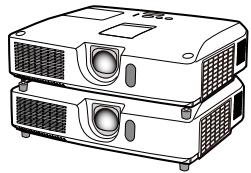
natural_image
Line drawing of two stacked projector units with ventilation grilles and a display screen (no text or symbols)Thank you for purchasing this product.
This manual is intended to explain only Instant Stack feature.
Other than what is mentioned in this manual, please see other manuals of this product.
Features
This projector can be used with another projector of the same type to project an image on the same screen using the Instant Stack feature.
The two projectors can be operated simultaneously to make the image brighter.
Moreover, if you connect two projectors with RS-232C cross-over cable, it turns to a kind of intellectual stacking system. The two projectors can work alternately by themselves, and once one projector has an accident the other voluntarily starts to work to keep your presentation going.
These features, generically called Instant Stack, provide you with the broad use.
⚠ WARNING ▶ Before using this product, be sure to read all manuals for this product. After reading them, store them in a safe place for future reference.
▶ Follow all the instructions in the manuals or on the product. The manufacturer assumes no responsibility for any damage caused by mishandling that is beyond normal usage defined in the manuals.
NOTE • The information in this manual is subject to change without notice.
- The manufacturer assumes no responsibility for any errors that may appear in this manual.
- The reproduction, transfer or copy of all or any part of this document is not permitted without express written consent.
Trademark acknowledgment
All the trademarks in this manual are the properties of their respective owners.
Contents
1. Introduction ......223
1.1 Entries and graphical symbols explanation.... 223
1.2 Important safety instruction ..... 223
Instant Stack feature....223
General installation 225
1.3 Basic information and preparations ...... 226
Instant Stack 226
Intellectual Stack and Simple Stack. 226
Remote control for Intellectual Stack and Simple Stack 226
Installation styles 226
Tentative terms for the two projectors226
2. Installation ......227
2.1 Preparing for Intellectual Stack 227
2.2 Installing
the first projector (Set A) ...... 228
Removing pocket caps 228
Preparing elevator feet 228
Deciding installation position ..... 228
Setting up Set A....229
2.3 Installing the second projector (Set B) ..... 231
Stacking the projectors 231
Connecting projectors....231
Setting up Set B....232
2.4 Confirming Main and Sub settings.... 233
2.5 Fine adjusting image position 234
For Intellectual Stack users ...... 234
For Simple Stack users.... 235
3. STACK menu settings ....236
3.1 Displaying STACK menu ...... 236
3.2 Selecting Main, Sub or off ..... 237
3.3 Selecting lamp operation mode 238
3.4 Selecting lamp switching mode 241
3.5 Selecting input source for Sub.. 242
3.6 Exiting Intellectual Stack menu 243
STACK menu 243
Dialog from STACK menu......243
3.7 Important information for Intellectual Stack 244
4. Connecting cables .....247
4.1 Connecting an RS-232C cable . 247
4.2 Connecting signal cables...... 248
Inputting image from Main to Sub....248
Inputting image to Sub and Main individually..... 248
5. Setting input ports using menu....249
5.1 Preparing for menu operations. 249
5.2 Checking Main projector's operating status.... 249
5.3 Starting up Main projector ..... 250
5.4 Setting the menu 251
Inputting image from Main to Sub - Computer signal 251
Inputting image from Main to Sub - Video signal
(either component or video) ...... 252
Inputting image to Sub and Main individually...... 252
6. Restrictions on Schedule function .....254
7. Troubleshooting .....256
1. Introduction
1.1 Entries and graphical symbols explanation
The following entries and graphical symbols are used for the manuals and the product as follows, for safety purpose. Please know their meanings beforehand, and heed them.
WARNING
This entry warns of a risk of serious personal injury or even death.
CAUTION
This entry warns of a risk of personal injury or physical damage.
NOTICE
This entry notices of fear of causing trouble.
1.2 Important safety instruction
The followings are important instructions for safely using the product in Instant Stack. First of all, read the following instructions and be sure to always follow them when using Instant Stack of this product.
Instant Stack feature
⚠ WARNING ▶ Take a special care not to fall the stacked projectors.
- When stacking two projectors, make sure the elevator feet and heel of the upper projector are inserted into the corresponding pockets of the lower projectors.
- When using the Instant Stack function by piling up two projectors, you can
change the projection angle by adjusting the elevator feet of the unit that is placed underneath. Exercise care to prevent the stacked projector from falling off or tipping over while adjusting the elevator feet.
- A maximum of two projectors can be stacked. Do not stack three or more projectors.
- Do not install the projectors that are stacked using the stack pockets, elevator feet and heel of this projector at a place higher than a person's height.
- Do not install the projectors that are stacked using the stack pockets, elevator feet and heel of this projector on a ceiling.
- Do not touch the stacked projectors except when instructions are given in this manual. Do not hit the projectors with any type of object.
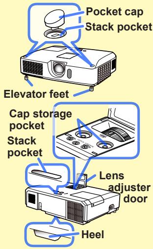
text_image
Pocket cap Stack pocket Elevator feet Cap storage pocket Stack pocket Lens adjuster door Heel(continued on next page)
⚠ WARNING ▶ When removing the pocket caps from the stack pockets, be sure to store them securely and safely inside the lens adjuster door to prevent children and pets from swallowing the caps. If swallowed, consult a physician immediately.
⚠️CAUTION ▶ Be careful not to injure your nail and finger when removing the pocket caps.
NOTICE ▶ Instant Stack is a feature that allows you to stack two projectors or arrange them side by side easily. Depending on the installation and surrounding environment, images projected from the two projectors may not superimpose well enough. The images cannot superimpose well enough especially when the screen is slanted, deformed or the surface is uneven.
- Images projected immediately after turning on the projectors are unstable due to rising internal temperature. Wait for more than 20 minutes before starting to adjust the superimposed images.
- The image positions may shift due to temperature change, vibration, or shock caused by hitting the projector. Install the projectors in a stable environment when using Instant Stack. If the image positions are shifted, readjust the images.
- The image positions may shift over time due to the tension and the weight of the connecting cables. Make sure not to impose any load on the projectors when arranging the cables.
- If the volume level of the built-in speakers is too high, the two projectors may resonate, noise may occur and the image quality may deteriorate. In this case, check the volume setting on both projectors. Lower the volume until the symptoms disappear or arrange the projectors side by side.
- When two projectors are connected using the RS-232C cable, the Main projector will be able to control the Sub projector. This feature is known as Intellectual Stack. When Intellectual Stack by means of RS-232C feature is used, RS-232C communication cannot be used to control the projector. If you wish to control the projectors, use the LAN connection that is connected to any of the projectors.
- When Intellectual Stack is used, the operations or settings of some functions are restricted. Refer to this manual for details.
General installation
⚠ WARNING ▶ Install the projector where you can access the power outlet easily.
▶ Do not subject the projector to unstable conditions. Install the projector in a stable horizontal position.
- Do not use any mounting accessories except the accessories specified by the manufacturer. Read and keep the manuals of the accessories used.
- For special installation such as ceiling mounting, be sure to consult your dealer beforehand. Specific mounting accessories and services may be required.
▶ Do not install the projector near thermally conductive or flammable things.
▶ Do not place the projector where any oils, such as cooking or machine oil, are used.
▶ Do not place the projector in a place where it may get wet.
⚠️CAUTION ▶ Place the projector in a cool place with sufficient ventilation.
- Keep a space of 30 cm or more between a side of the projector and other objects such as a wall. If you install two projectors in Style 2, keep a space of 30 cm or more between the two projectors.
- Do not stop up, block nor cover the projector's vent holes.
- Do not place the projector at places that are exposed to magnetic fields, doing so can cause the cooling fans inside the projector to malfunction.
▶ Avoid placing the projector in smoky, humid or dusty place. - Do not place the projector near humidifiers. Especially for an ultrasonic humidifier, chlorine and minerals contained in tap water are atomized and could be deposited in the projector causing image degradation or other problems.
NOTICE ▶ Position the projector to prevent light from directly hitting the projector's remote sensor.
- Do not place the product in a place where radio interference may be caused.
1.3 Basic information and preparations
Instant Stack
Instant Stack is a feature that allows you to superimpose images projected from two projectors easily. This projector is designed to provide this feature, with functions to install two projectors and superimpose the images.
Intellectual Stack and Simple Stack
Instant Stack includes the following two features.
When two projectors are connected via an RS-232C cable with necessary settings performed on the projectors, these two projectors will automatically operate in synchronization with each other according to the settings. This is known as Intellectual Stack in this manual.
The two projectors operate individually without the RS-232C connection. This is known as Simple Stack in this manual.
Remote control for Intellectual Stack and Simple Stack
For Intellectual Stack, one projector is set as Main and the other is set as Sub. Only the Main projector is capable of receiving the remote control signals. To operate the Sub projector, you need to point the remote control at the Main projector. For Simple Stack, both projectors can receive the remote control signals. To avoid crosstalk when operating with the remote control, it is recommended to operate one projector with the remote control and the other with the control panel on the projector or a wired remote control. In this case, disable the remote control receiving on the other projector with the KEY LOCK feature. (Operating Guide → OPTION menu)
Installation styles
Following are two styles to install the projectors. Instant Stack supports both styles.
Style 1 : Stack vertically
Style 2 : Arrange side by side
The descriptions in this manual are mainly on Style 1 installation. If you wish to install two projectors in Style 2, refer to the descriptions required in this manual.
Tentative terms for the two projectors
For better understanding of the descriptions in this manual, the following terms are used when explaining the vertical stacking installation.
Set A : Projector placed underneath
Set B : Projector placed on top of Set A
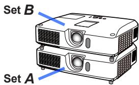
text_image
Set B Set A2. Installation
For safety reasons, read 1.2 Important safety instruction carefully before installation. In addition, take note of the followings for proper use of Instant Stack.
- When using Intellectual Stack, both projectors will respond to the remote control signals until STACK MODE on either projector is set to SUB.
During installation, it is recommended to operate one projector with the remote control and the other with the control panel on the projector or a wired remote control. In this case, disable the remote control receiving on the other projector with the KEY LOCK feature. (Operating Guide → OPTION menu)
- Images from Set A and Set B may superimpose well but the image positions can shift over time.
Readjust to superimpose the images.
- If the volume level of the built-in speakers is too high, the two projectors may resonate, noise may occur and the image quality may deteriorate.
In this case, check the volume setting on both projectors. Lower the volume until the symptoms disappear or arrange the projectors side by side. If the image positions are shifted, readjust.
2.1 Preparing for Intellectual Stack
When using Intellectual Stack via RS-232C connection, ensure the following settings are set on the two projectors. Otherwise, the Intellectual Stack menu cannot be operated.
- STANDBY MODE in SETUP menu: NORMAL (Operating Guide → SETUP menu)
- COMMUNICATION TYPE under COMMUNICATION in SERVICE menu: OFF (Operating Guide → OPTION menu)
- STACK LOCK in SECURITY menu: OFF
When STACK LOCK is set to on, menus related to Instant Stack cannot be operated. It is therefore necessary to set it to off during installation and menu setting.
(1) Use the ▲/▼/◄/► buttons to go into the following menu.
ADVANCED MENU > SECURITY
STACK LOCK
STACK LOCK dialog will appear on screen. (Operating
Guide → SECURITY menu)

(2) Use the ▲/▼ buttons to highlight OFF, and press the ▶ button to complete the setting.
2.2 Installing the first projector (Set A)
Removing pocket caps
When stacking the two projectors, remove the pocket caps on Set A.
⚠️CAUTION ▶ It is recommended to use a pin or the like to remove the caps. If you are using finger, be careful not to injure your nail and finger.
NOTE • Cap storage pockets for the pocket caps are inside the lens adjuster door. Be sure to keep the caps in the storage pockets after removing the caps from the stack pockets.
To store the cap to the pocket, place the thin end of the cap into the pocket first, then push the other side of the cap down firmly to the bottom of the pocket. It is important to ensure that the caps are securely stored to prevent children and pets from swallowing them.
Preparing elevator feet
When stacking the two projectors, set the length of the elevator feet to the minimum using the elevator buttons on Set A and B.
⚠️CAUTION ▶ Be careful when stacking the two projectors, the projector on top may slide down.
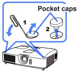
text_image
Pocket caps 1 2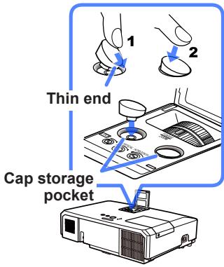
text_image
1 2 Thin end Cap storage pocket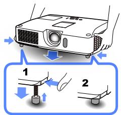
text_image
Diagram illustrating a projector setup with labeled components and directional arrows indicating motion or movement.Deciding installation position
Decide the position of Set A and its projection angle. (User's Manual (concise) → Arrangement and Adjusting the projector's elevator.)
NOTE • Set the tilt angle of Set A to within 12 degrees from the level line.
• Take the followings into account when considering the installation position.
- VERTICAL adjuster should be set to the upper limit position.
- ZOOM ring should not be set to the widest position.
- HORIZONTAL adjuster is recommended to be set near the center position.
Setting up Set A
- Turn on Set A.
- Set the lens position to the upper limit with the VERTICAL adjuster.
NOTE • If it is not set to the upper limit, the image of Set B may not superimpose well enough to the image of Set A.
- Perform the MIRROR setting first if necessary as it may change the image position. (Operating Guide → SETUP menu)
-
HORIZONTAL adjuster is recommended to be set near the center position.
-
Adjust the image of Set A to fit the screen with the VERTICAL adjuster, HORIZONTAL adjuster, ZOOM ring and FOCUS ring. (User's Manual (concise) → Displaying the picture)
Adjust the image position using KEYSTONE and PERFECT FIT if necessary. (Operating Guide → EASY MENU or SETUP menu)
NOTE • Do not adjust ZOOM ring to the widest position, otherwise the image of Set B may not superimpose well enough to the image of Set A. Fine adjusting the image position of Set B electrically does not increase its image size. Use the ZOOM ring to adjust the image size of Set B to slightly larger than Set A.
- KEYSTONE cannot be operated when PERFECT FIT is in use. To adjust the image using both KEYSTONE and PERFECT FIT, adjust KEYSTONE first.
-
If you are using Simple Stack, go to 2.3 Installation of the second projector (Set B).
-
Display the menu with the MENU button. (Operating Guide → Using the menu function)
-
Use the ▲/▼/◄/► buttons to go into the following menu.
ADVANCED MENU > OPTION
SERVICE > COMMUNICATION
STACK
STACK menu will appear on screen. (Operating Guide → OPTION menu)
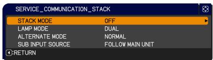
text_image
SERVICE_COMMUNICATION_STACK STACK MODE OFF LAMP MODE DUAL ALTERNATE MODE NORMAL SUB INPUT SOURCE FOLLOW MAIN UNIT C:RETURN(continued on next page)
2.2 Installing the first projector (Set A) - Setting up Set A (continued)
- Use the ▲/▼ buttons to highlight STACK MODE, and press the ▶ button to display the STACK MODE dialog.
Highlight SUB pressing the ▲/▼ buttons, and press the ▶ button.
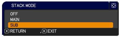
text_image
STACK MODE OFF MAIN SUB :RETURN :EXIT- After pressing the ▶ button, a dialog to confirm whether or not to save the setting is displayed.
Press the ▶ button to complete the setting.

text_image
SERVICE_COMMUNICATION_STACK ARE YOU SURE YOU WISH TO CHANGE STACK SETTING ? :NO :YES- If you are using Intellectual Stack, disable the remote control receiving using KEY LOCK. (Operating Guide → OPTION menu)
NOTE • Set A will not be operated by the remote control hereafter. To avoid crosstalk when operating with the remote control, it is recommended to disable the remote control receiving using KEY LOCK.
- After the STACK MODE setting is completed, Set A (Sub) will not be able to receive the remote control signals. When STACK MODE is set to OFF, enable the remote control receiving using KEY LOCK if necessary.
2.3 Installing the second projector (Set B)
Stacking the projectors
- Place Set B on Set A when stacking the two projectors. Make sure the heel on the bottom of Set B is inserted into the corresponding pocket on the top of Set A.
- With Set B placed on Set A, push the elevator buttons of Set B to extend the elevator feet without lifting Set B. Make sure the elevator feet reach the bottom of the stack pockets on Set A.
⚠CAUTION ▶Be careful when stacking the two projectors, the projector on top may slide down.
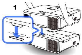
text_image
1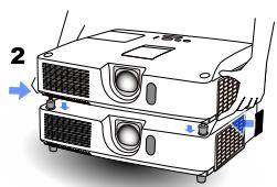
natural_image
Diagram of a projector unit with labeled components and directional arrows (no text or symbols beyond labels)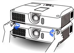
natural_image
Illustration of a projector with hands operating it, showing front panel and side view (no text or symbols)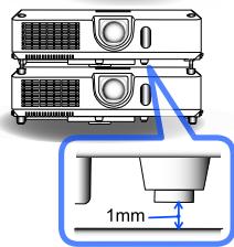
text_image
1mm- Rotate the elevator feet of Set B
twice in the counterclockwise direction and leave a gap of about 1 mm between the protrusion at the bottom of Set B and the top of Set A as shown in the figure.
NOTE • It is necessary to keep Set B slightly away from Set A except for the heel portion to prevent the two projectors from resonating due to the sound output from the built-in speakers.
- If Set ±bB is tilt further, the image of Set ±bB may not be superimposed to the image of Set ±bA .
- If the elevator feet of Set A are used, make sure the tilt angle for both sets is within 12 degrees from the level line.
Connecting projectors
To use Intellectual Stack, connect an RS-232C cross cable between the CONTROL port of Set A and Set B.
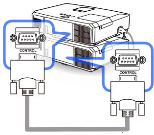
text_image
Diagram showing two connected electronic devices with labeled 'CONTROL' indicators and connecting cables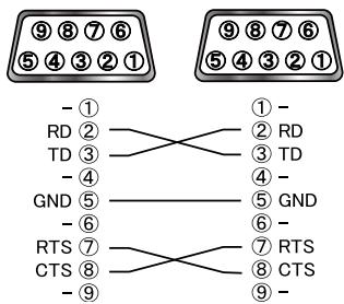
text_image
⑨⑧⑦⑥ ⑤④③②① -① RD② TD③ -④ GND⑤ -⑥ RTS⑦ CTS⑧ -⑨ ①- ② RD ③ TD -④ GND⑤ -⑤ GND -⑥ ⑦ RTS ⑧ CTS -⑨Setting up Set B
1. Turn on Set B.
NOTE • After turning on Set B, make sure the image of Set B is not significantly tilted compared to the image of Set A. If the image is overly tilted, rotate the elevator feet of Set B to adjust the angle such that the tilt is just about right. Check again that there is a gap of about 1 mm between the protrusion at the bottom of Set B and the top of Set A.
2. Reset the adjustment of KEYSTONE and PERFECT FIT on Set B. (Operating Guide → EASY MENU or SETUP menu)
NOTE • KEYSTONE cannot be operated when PERFECT FIT is in use. To reset both functions, reset PERFECT FIT first.
- Perform the MIRROR setting first if necessary as it may change the image position. (Operating Guide → SETUP menu)
3. Adjust the image size and position of Set B with the ZOOM ring, VERTICAL adjuster, HORIZONTAL adjuster and FOCUS ring such that the image can be superimposed well to the image of Set A.
NOTE • Fine adjustment of the image size and position thereafter with functions such as KEYSTONE and PERFECT FIT does not increase the image size. It is therefore important to have the image of Set B completely overlapping the image of Set A.
- When controlling Set B with the remote control, Set A may also respond to the remote control. It is recommended to control Set B with the control panel on Set B .
- When two projectors are arranged side by side, adjust the image of Set B to superimpose well to the image of Set A.
- If you are using Simple Stack, it is recommended to disable the remote control receiving on Set B using KEY LOCK and operate using the control panel or a wired remote control as Set A will respond to the remote control. (Operating Guide → OPTION menu)
- If you are using Simple Stack, go to For Simple Stack users.
4. Display the menu with the MENU button. (Operating Guide → Using the menu function)
5. Use the ▲/▼/◄/► buttons to go into the following menu.
ADVANCED MENU > OPTION
SERVICE > COMMUNICATION
STACK
STACK menu will appear on screen. (Operating Guide → OPTION menu)
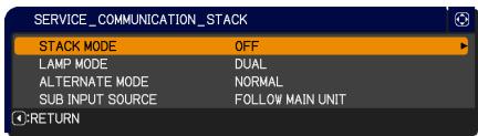
text_image
SERVICE_COMMUNICATION_STACK STACK MODE OFF LAMP MODE DUAL ALTERNATE MODE NORMAL SUB INPUT SOURCE FOLLOW MAIN UNIT RETURN(continued on next page)
2.3 Installing the second projector (Set B) - Setting up Set B (continued)
- Use the ▲/▼ buttons to highlight STACK MODE, and press the ▶ button to display the STACK MODE dialog.
Highlight MAIN with the ▲/▼ buttons, and press the ◀ button to return to the previous menu.
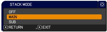
text_image
STACK MODE OFF MAIN SUB RETURN , EXIT- Use the ▲/▼ buttons to highlight LAMP MODE, and press the ▶ button to display the LAMP MODE dialog.
Highlight DUAL with the ▲/▼ buttons, and press the ▶ button.
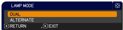
text_image
LAMP MODE DUAL ALTERNATE :RETURN , :EXIT- After pressing the ▶ button, a dialog to confirm whether or not to save the setting is displayed.
Press the ▶ button to complete the setting.

text_image
SERVICE_COMMUNICATION_STACK ARE YOU SURE YOU WISH TO CHANGE STACK SETTING ? :NO :YES2.4 Confirming Main and Sub settings
- Press the MENU button on the remote control for Main (Set B).
NOTE • When Intellectual Stack is in use, only Main is capable of receiving the remote control signals, Sub will not respond to the remote control signals.
- The following dialogs appear on the lower right screen.

text_image
MENU MAIN SUB :EXIT , :OKMain (Set B)

natural_image
Solid dark gray rectangle with no visible text, symbols, or features.Sub (Set A)
- If you press the ▶ button, the dialog closes and the Main (Set B) menu will appear when MAIN is highlighted.
If you press the ◀ button, the dialog closes and the menu will disappear.
NOTE • If these dialogs are not displayed on screen, check the RS-232C connection and the MAIN or SUB setting in the STACK MODE dialog.
2.5 Fine adjusting image position
To superimpose the images of Main (Set B) and Sub (Set A), fine adjust the image size and position of Main (Set B) using PERFECT FIT.
For Intellectual Stack users
- Press the MENU button on the remote control or the control panel on Main (Set B) to display the MENU dialog.
Highlight MAIN with the ▲/▼ buttons, and press the ▶ button.
Menu on Main (Set B) will appear.
- Using the ▲/▼/◄/► buttons on the remote control or the control panel on Main (Set B), select PERFECT FIT from EASY MENU, or the SETUP menu of ADVANCED MENU.
(Operating Guide → EASY MENU or SETUP menu)
The image for Intellectual Stack appears on screen. This image includes a TEMPLATE screen with the PERFECT FIT dialog from Main (Set B) and another TEMPLATE screen from Sub (Set A).
- Using PERFECT FIT on Main (Set B), adjust the image size and position of Main (Set B) to superimpose well to the image of Sub (Set A). (Operating Guide → EASY MENU or OPTION menu)
It is recommended to adjust in the following ways.
(1) Roughly adjust the four corners in the order below.
Top left → Top right → Bottom right → Bottom left
(2) Fine adjust the four corners in the same way.

text_image
MENU MAIN SUB :EXIT , :OKMain (Set B)
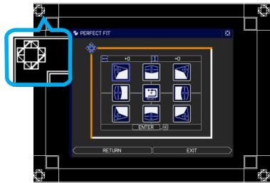
text_image
PERFECT FIT +0 +1 -0 ENTER 3 RETURN EXITImage from Main (Set B)

natural_image
Pure geometric diagram with a blue outline and grid pattern, no text or symbols presentImage from Sub (Set A)
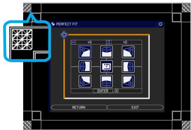
text_image
PERFECT FIT +0 +0 ENTER RETURN EXITSuperimposed image
NOTE • Refer to NOTES for all users.
For Simple Stack users
- Press the MENU button on the remote control to display the menu on Set A.
- Use the ▲/▼/◄/► buttons to open the TEMPLATE dialog, then select STACK on the dialog. (Operating Guide → SCREEN menu)
- Press the MENU button on the control panel of Set B to display the menu.
- Use the ▲/▼/◄/► buttons to select PERFECT FIT from EASY MENU, or the SETUP menu of ADVANCED MENU. (Operating Guide → EASY MENU or SETUP menu) PERFECT FIT dialog appears on screen.
- Using PERFECT FIT on Set B, adjust the image size and position of Set B to superimpose well to the image of Set A. It is recommended to adjust in the following ways.
(1) Roughly adjust the four corners in the order below.
Top left → Top right → Bottom right → Bottom left
(2) Fine adjust the four corners in the same way.
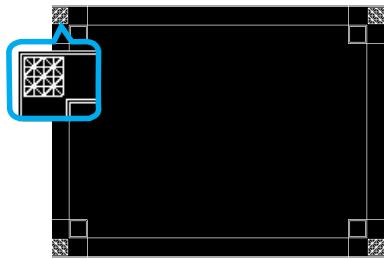
natural_image
Pure geometric diagram with a blue arrow pointing to a grid pattern inside a rectangle (no text or symbols)STACK of TEMPLATE
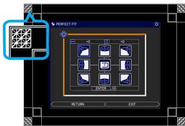
text_image
PERFECT FIT 2 0 1 0 ENTER 0 RETURN EXITPERFECT FIT dialog on STACK of TEMPLATE
NOTES for all users • For details on PERFECT FIT, refer to PERFECT FIT of EASY MENU or OPTION menu in the Operating Guide.
- When arranging the projectors side by side (Style 2), it is also necessary to adjust the image position of one projector in accordance with the other projector as explained above.
- It is strongly recommended to use a flat screen. If a curved or skewed screen is used, it is very difficult to align the two images even if you use the pin/barrel adjustment of PERFECT FIT.
-
Even through fine adjustment of the images from the two projectors, it may not be possible to superimpose the images well enough depending on the input signals. In this case, try the following methods.
-
Press the AUTO button on the remote control or execute AUTO ADJUST EXECUTE (Operating Guide → IMAGE menu) on each of the projectors.
- Adjust H POSITION and V POSITION (Operating Guide → IMAGE menu) on each of the projectors.
- Check the RESOLUTION setting in the INPUT menu, and change to the same setting if the setting differs between Main and Sub. (Operating Guide → INPUT menu)
3. STACK menu settings
Set the Intellectual Stack operation using the STACK menu.
NOTE • If you are using Simple Stack without RS-232C connection, skip this chapter.
- If you do not need to change the settings made during the installation explained prior to this chapter, go to 3.3 Selecting lamp operation mode.
- Read 3.7 Important information for Intellectual Stack carefully.
3.1 Displaying STACK menu
Use the ▲/▼/◄/► buttons to go into the following menu.
ADVANCED MENU > OPTION
SERVICE > COMMUNICATION > STACK STACK menu will appear on screen. (Operating Guide → OPTION menu) The setting for
Intellectual Stack operation starts from this menu.
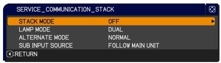
text_image
SERVICE_COMMUNICATION_STACK STACK MODE OFF LAMP MODE DUAL ALTERNATE MODE NORMAL SUB INPUT SOURCE FOLLOW MAIN UNIT RETURNNOTE • Check that the following settings are made on both projectors.
Otherwise, STACK menu on the projectors cannot be operated.
- STANDBY MODE in SETUP menu: NORMAL (Operating Guide → SETUP menu)
- COMMUNICATION TYPE under COMMUNICATION in SERVICE menu: OFF (Operating Guide → OPTION menu)
- STACK LOCK in SECURITY menu: OFF
3.2 Selecting Main, Sub or off
To enable Intellectual Stack, select either MAIN or SUB. Intellectual Stack starts when one projector is set to MAIN and the other is set to SUB in the STACK MODE dialog. To disable Intellectual Stack, select OFF.
- Highlight STACK MODE in the STACK menu with the ▲/▼ buttons, then press the ▶ button to display the STACK MODE dialog.
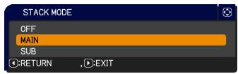
text_image
STACK MODE OFF MAIN SUB RETURN EXIT- Use the ▲/▼ buttons in the dialog to highlight MAIN, SUB or OFF.
OFF: Disables Intellectual Stack.
MAIN: Sets the projector to Main that functions as a control tower.
SUB: Sets the projector to Sub that functions as a follower.
- Press the ◀ button to return to the previous menu, or press the ▶ button to complete the setting.
NOTE • After setting Main or Sub, the setting information can be checked on Web Control. (Network Guide → Web Control) Select Projector Status in the main menu of Web Control. The Stack Mode item shows whether your projector is set to MAIN or SUB even if STACK MODE is set to OFF.
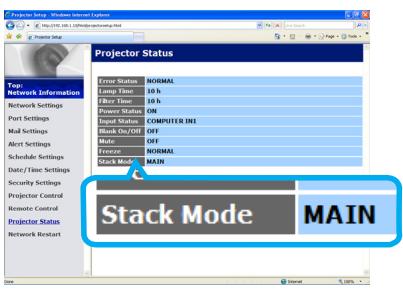
text_image
Projector Status Error Status NORMAL Lamp Time 10 h Clear Time 10 h Delivery Status ON Input Status COMPUTER IN1 Block Day OFF Mode OFF Event Normal Stack Mode MAIN Stack Mode MAIN3.3 Selecting lamp operation mode
Select the DUAL or ALTERNATE lamp operation mode.
- Highlight LAMP MODE in the STACK menu with the ▲/▼ buttons, then press the ▶ button to display the LAMP MODE dialog.
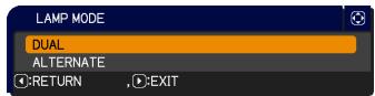
text_image
LAMP MODE DUAL ALTERNATE RETURN , EXIT- Use the ▲/▼ buttons in the dialog to highlight DUAL or ALTERNATE.
DUAL: Turns on the projectors at the same time.
ALTERNATE: Turns on the projectors alternately.
- Press the ◀ button to return to the previous menu, or press the ▶ button to complete the setting.
NOTE • If DUAL is selected, a menu to select MAIN or SUB appears on screen when a button on the control panel of the projector or remote control is pressed. Select the projector that you want to operate. Refer to the examples below.
- When the MENU button is pressed, a menu to select MAIN or SUB is displayed. If MAIN is selected, EASY MENU or ADVANCED MENU of the Main projector is displayed.
- When the KEYSTONE button is pressed, a menu to select MAIN or SUB is displayed. If MAIN is selected, KEYSTONE menu of the Main projector is displayed.
- When DUAL is selected for LAMP MODE, there are operating restrictions as follows.
- AUTO POWER OFF and FREEZE functions on both projectors are disabled.
- The test patterns for CUSTOM of GAMMA and COLOR TEMP are not displayed.
- It takes slightly longer time to turn on the projectors. This is not a malfunction.
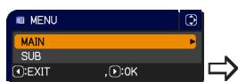
text_image
MENU MAIN SUB EXIT OKMenu to select MAIN or SUB
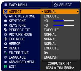
text_image
EASY MENU ASPECT AUTO KEYSTONE KEYSTONE KEYSTONE PERFECT FIT PICTURE MODE ECO MODE MIRROR RESET FILTER TIME LANGUAGE ADVANCED MENU EXIT NORMAL EXECUTE +0 +0 EXECUTE NORMAL NORMAL EXECUTE Oh ENGLISH COMPUTER IN 1 1024 x 758 @60HzMenu on Main projector

text_image
KEystone MAIN SUB :EXIT , :OKMenu to select MAIN or SUB
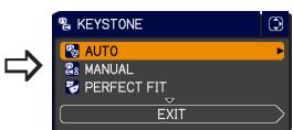
text_image
KEystone AUTO MANUAL PERFECT FIT EXITMenu on Main projector
(continued on next page)
NOTE • When DUAL is selected for LAMP MODE, the images projected from the Main and Sub projectors may be different. It is recommended to set the projectors as follows.
- Set the same image for TEMPLATE and START UP on the Main and Sub projectors.
- Capture the same image for MyScreen on the Main and Sub projectors.
- Save the same image on MY IMAGE on the Main and Sub projectors.
- Set the same message content for the Messenger function (Network Guide → Messenger Function) on the Main and Sub projectors.
- When DUAL is selected for LAMP MODE, image shift can result in image quality degradation on the screen. Perform the MIRROR setting before adjusting the image position as the image position will change when the MIRROR setting is changed. (Operating Guide → SETUP menu)
- When ALTERNATE is selected and an error occur on the projector in operation causing the lamp to turn off, the other projector will automatically start to operate. However, if the RS-232C cable is disconnected or AC power is not supplied, the other projector will not turn on.
- In cases when PIN LOCK or TRANSITION DETECTOR on both projectors is set to ON (Operating Guide → SECURITY menu), the two projectors will not turn on even if ALTERNATE is selected. Enter the security code on both projectors and one of the projectors will turn on.
- When Intellectual Stack is in use, the POWER indicator on the control panel of the projector operates differently than normal. (Operating Guide → Troubleshooting) When the Main and Sub projectors are in standby mode, the Main projector determines which projector to turn on according to the STACK MODE setting if the STANDBY/ON button on the remote control or control panel of the Main projector is pressed.
- The POWER indicator on the Main projector blinks in green while the Main projector determines which projector to turn on.
- If the Main projector is turned on, the POWER indicator on the Main projector turns to steady green after lighting up, as per normal.
- If the Sub projector is turned on, the POWER indicator on the Main projector lights in orange after the Sub projector is turned on.
- If an error occurs on the Main projector, the Sub projector turns on and the POWER indicator on the Main projector lights or blinks in red.
3.4 Selecting lamp switching mode
The following setting is necessary only when ALTERNATE is selected in the LAMP MODE dialog. Select the AUTO or NORMAL lamp switching mode when using ALTERNATE.
- Highlight ALTERNATE MODE in the STACK menu with the ▲/▼ buttons, then press the ▶ button to display the ALTERNATE MODE dialog.

text_image
ALTERNATE MODE AUTO NORMAL :RETURN , EXIT- Use the ▲/▼ buttons in the dialog to highlight AUTO or NORMAL.
AUTO: Turns on the projector with the least lamp usage.
NORMAL: Turns on the projector that was not used the previous time.
- Press the ◀ button to return to the previous menu, or press the ▶ button to complete the setting.
NOTE • The ALTERNATE MODE dialog can be operated on the Main projector when ALTERNATE is selected in the LAMP MODE dialog.
- To maintain the quality and reliability of the two projectors, the projector with the most lamp usage may be turned on even if AUTO is selected.
3.5 Selecting input source for Sub
- Highlight SUB INPUT SOURCE in the STACK menu with the ▲/▼ buttons, then press the ▶ button to display the SUB INPUT SOURCE dialog.

text_image
SUB INPUT SOURCE FOLLOW MAIN UNIT FIXED (COMPUTER IN 1) RETURN , EXIT- Use the ▲/▼ buttons in the dialog to highlight FOLLOW MAIN UNIT or FIXED (COMPUTER IN 1).
FOLLOW MAIN UNIT: Sets the input source on the Sub projector to the same port as Main.
FIXED (COMPUTER IN 1): Sets the input source on the Sub projector to the COMPUTER IN1 port which is connected to the MONITOR OUT port on the Main projector.
- Press the ◀ button to return to the previous menu, or press the ▶ button to complete the setting.
NOTE • If FIXED (COMPUTER IN 1) is selected, either the COMPUTER IN1 or IN2 port can be selected as an input source on the Main projector. When the COMPUTER or VIDEO button on the remote control or the INPUT button on the projector is pressed, the MAIN INPUT SOURCE dialog will be displayed on screen. Select COMPUTER IN 1 or COMPUTER IN 2 with the ▲/▼ buttons.
- If FIXED (COMPUTER IN 1) is selected, the COMPUTER IN1 port on the Sub projector should be connected to the MONITOR OUT port on the Main projector with a computer cable. The image from the selected port is output from the MONITOR OUT port on the Main projector to the COMPUTER IN1 port on the Sub projector. The MONITOR OUT setting on the Main projector is disabled when FIXED (COMPUTER IN 1) is selected. (Operating Guide → SETUP menu)
- If FIXED (COMPUTER IN 1) is selected, video signals can be input to the COMPUTER IN1 or IN2 port on the Main projector. Set the port for video signal input in the COMPUTER IN menu and set the video format in the VIDEO FORMAT menu. Refer to Inputting image from Main to Sub and Inputting image from Main to Sub - Video signal (either component or video).
3.6 Exiting Intellectual Stack menu
Before exiting menu operation for Intellectual Stack, it is recommended to check all the settings in the STACK menu. For dialogs that are called from the STACK menu, you can press the ◀ button to return to the STACK menu.
Refer to the following to exit menu operation for Intellectual Stack.
STACK menu
When you press the ◀ button (functioning as RETURN key) after performing some changes to the settings, a confirmation dialog will appear.
- Pressing the ▶ button (functioning as YES key) in the dialog saves the setting and
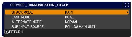
text_image
SERVICE_COMMUNICATION_STACK STACK MODE MAIN LAMP MODE DUAL ALTERNATE MODE NORMAL SUB INPUT SOURCE FOLLOW MAIN UNIT RETURN
text_image
SERVICE_COMMUNICATION_STACK ARE YOU SURE YOU WISH TO CHANGE STACK SETTING ? :NO :YEScloses the dialog. The screen becomes black while the setting is being applied. Please wait for a while.
- Pressing the ◀ button (functioning as NO key) in the dialog returns you to the COMMUNICATION menu without saving the setting. (Operating Guide → OPTION menu → SERVICE)
Dialog from STACK menu
When you press the ▶ button (functioning as EXIT key) after performing some changes to the settings, a confirmation dialog will appear.
- Pressing the ▶ button (functioning as YES key) in the dialog saves the setting and closes
the dialog. The screen becomes black while the setting is being applied. Please wait for a while.
- Pressing the ◀ button (functioning as NO key) in the dialog closes the dialog without saving the setting.

text_image
SUB INPUT SOURCE FOLLOW MAIN UNIT FIXED (COMPUTER IN 1) :RETURN , :EXIT
text_image
SERVICE_COMMUNICATION_STACK ARE YOU SURE YOU WISH TO CHANGE STACK SETTING ? :NO :YES3.7 Important information for Intellectual Stack
This section provides important information for setting up the Main and Sub projectors, not explanations on operating the menus. Read all information carefully.
- To use Intellectual Stack, one projector must be set to Main and the other set to Sub.
- When stacking the two projectors, the control panel of the projector placed underneath cannot be operated. It is therefore strongly recommended to set the projector underneath to Sub and the projector on top to Main.
- All buttons except the STANDBY/ON button on the control panel of the Sub projector are disabled. Operate the projectors with the control panel of the Main projector or the remote control.
- Pressing the STANDBY/ON button of the Sub projector does not allow you to turn off only the Sub projector. The Main and Sub projectors turn off when the button is pressed for more than 3 seconds. And pressing the button does not turn on the Main or Sub projector.
- The Main projector is capable of receiving the remote control signals but not the Sub projector so the remote control should be pointed at the Main projector.
- If a wired remote control is used, connect the cable to the Main projector instead of the Sub projector.
- For simple PC mouse & keyboard functions, connect both the Main and Sub projectors to your computer with USB cables. (Operating Guide → Using as a simple PC mouse & keyboard)
- AUTO SEARCH function is disabled when the projector is used in Intellectual Stack.
- Network communication to Sub and Web Control on Sub cannot turn on the Sub projector. The Sub projector can only be controlled through the Main projector.
- Remote Control function on Web Control of the Sub projector is disabled. (Network Guide → 3.11 Remote Control)
- If you try to turn on the projectors using the Power on & Display on feature on the Messenger function, the projectors will exit Intellectual Stack and display the specified message. To start Intellectual Stack again, re-select MAIN/SUB on both projectors in the STACK MODE dialog, or turn off and on both projectors again.
- The Main and Sub projectors have the following common settings.
- Muting feature (Operating Guide → Temporarily muting the sound)
- Magnifying feature (Operating Guide → Using the magnify feature)
- ASPECT and OVER SCAN (Operating Guide → IMAGE menu)
- COMPUTER IN (Operating Guide → INPUT menu)
- MESSEAGE (Operating Guide → SCREEN menu)
- MY BUTTON (Operating Guide → OPTION menu)
- TEMPLATE (Operating Guide → SCREEN menu)
3.7 Important information for Intellectual Stack (continued)
- The following functions are disabled.
- Executing of AUTO KEYSTONE (Operating Guide → SETUP menu)
- STANDBY MODE (Operating Guide → SETUP menu)
- AUTO SEARCH (Operating Guide → OPTION menu)
- Turning on/off AUTO KEYSTONE (Operating Guide → OPTION menu)
- DIRECT POWER ON (Operating Guide → OPTION menu)
- MY SOURCE (Operating Guide → OPTION menu)
- COMMUNICATION TYPE (Operating Guide → OPTION menu → SERVICE → COMMUNICATION)
- The input source from the following ports cannot be selected.
- USB TYPE A, USB TYPE B, LAN
- When Intellectual Stack is in use, an error message will be displayed if an error occurs on any of the projectors.
When an error occurs, a full dialog will be displayed on screen. The full dialog changes to a small dialog after about 20 seconds without any key activity.
While the small dialog is displayed, pressing the ◀ button displays a full dialog again.

text_image
Filter Error Cold Error EXIT Full dialog
Small dialog
The numbers “1” and “2” above the projector icons represent the Main and Sub projectors respectively.
Refer to the on-screen messages as shown below and take the necessary actions to resolve the problem.
Example:
Cover Error: Lamp cover is opened.
Lamp Error: Lamp does not light up.
Fan Error: Problem with cooling fan.
Temp Error: Temperature of the projector is too high.
Air Flow Error: Temperature of the projector is too high, check that the exhaust vents are not blocked.
Filter Error: The reading on the filter timer exceeds the hours set in the FILTER MESSAGE menu. (Operating Guide → OPTION menu → SERVICE)
Cold Error: The ambient temperature is too low.
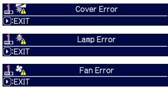
text_image
Cover Error EXIT Lamp Error EXIT Fan Error EXIT


3.7 Important information for Intellectual Stack (continued)
- If you need to turn off a projector for reasons such as taking corrective actions for an error, turn off both the projectors so that Intellectual Stack can be started properly when the projectors are turned on again.
- If the PIN LOCK or TRANSITION DETECTOR security function on both projectors is set to ON, both projectors will turn on. Enter the security code for Main first then followed by Sub. If ALTERNATE mode is selected, one of the projectors will turn off automatically. (Operating Guide → SECURITY menu)
- If the PIN LOCK or TRANSITION DETECTOR security function on one of the projectors is set to ON, it is necessary to enter the security code as follows when turning on the projector.
- In DUAL mode, both projectors will turn on. Enter the security code for the projector that is locked by the security function.
- In ALTERNATE mode, if the projector locked by the security function is due to turn on according to the ALTERNATE mode setting, only that projector will turn on. Otherwise, both projectors will turn on. Enter the security code for the projector that is locked by the security function. After the security lock is released, one of the projectors will turn off if both projectors are turned on.
4. Connecting cables
To superimpose two images onto one screen, the same image must be input to the Main and Sub projectors. There are various methods to input the image to the projectors. This chapter describes the ways of connecting the cables. Read this chapter to find a method that meets your needs.
NOTE • If Simple Stack without an RS-232C connection is used, the Main and Sub projectors described below do not exist. Main in this chapter is read as one projector and Sub as the other projector.
- For details on the specifications of the input ports, refer to Connecting with your devices (Operating Guide → Setting up) and Connection to the ports. (Operating Guide - Technical)
4.1 Connecting an RS-232C cable
If you are using Intellectual Stack, connect an RS-232C cross cable between the RS-232C ports on the Main and Sub projectors. This connection is not required if you are using Simple Stack.
NOTE • If the RS-232C cable connecting the two projectors operating in Intellectual Stack is disconnected, the projectors will exit from Intellectual Stack and start to operate individually. Intellectual Stack will not restart even if the cable is reconnected. Follow the procedures below to restart Intellectual Stack.
(1) Do not operate the projectors for more than 10 seconds after disconnecting the cable to allow the projectors to recognize the disconnection of the cable.
(2) Turn off both projectors and allow them to cool sufficiently.
(3) Reconnect the two projectors with the RS-232C cable and turn them on again. Intellectual Stack will restart.
4.2 Connecting signal cables
There are two methods to input image to the Sub projector.
- Inputting image from the MONITOR OUT port on Main to Sub.
- Inputting image to Sub and Main individually.
Inputting image from Main to Sub
- Connect the MONITOR OUT port on Main to the COMPUTER IN1 port on Sub with a computer cable.
- Connect the image output device to one of the input ports on Main.
NOTES for Intellectual Stack
- COMPUTER IN1 and IN2 can be used as the input port for the Main projector in Intellectual Stack. Do not use other ports for image input.
- You can input component signals to COMPUTER IN1 and IN2.
- You can input video signals to the Y pin of the component video of COMPUTER IN1 and IN2.
NOTES for Simple Stack
- COMPUTER IN1 and IN2 can be used as the input port for the projector that is connected with a computer cable at its MONITOR OUT port. (Operating Guide → SETUP menu) If you wish to use other input ports, input the image to Sub and Main individually.
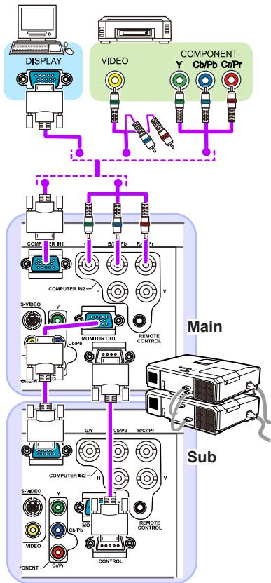
flowchart
graph TD
    A["DISPLAY"] --> B["COMPUTER IN1"]
    C["VIDEO"] --> D["COMPUTER IN2"]
    E["COMPONENT Y"] --> F["Ch/Pb"]
    E --> G["Cr/Pr"]
    B --> H["MONITOR OUT"]
    D --> I["Remote Control"]
    H --> J["Computer IN2"]
    I --> K["Computer IN2"]
    J --> L["Main"]
    K --> M["Sub"]
    L --> N["Main"]
    M --> O["Sub"]
    N --> P["Remote Control"]
    P --> Q["Main"]
    style A fill:#f9f,stroke:#333
    style C fill:#f9f,stroke:#333
    style E fill:#f9f,stroke:#333
    style B fill:#ccf,stroke:#333
    style D fill:#ccf,stroke:#333
    style H fill:#cff,stroke:#333
    style I fill:#cff,stroke:#333
    style J fill:#ffc,stroke:#333
    style K fill:#ffc,stroke:#333
    style L fill:#ffc,stroke:#333
    style M fill:#ffc,stroke:#333
    style N fill:#ffc,stroke:#333
    style O fill:#cfc,stroke:#333
    style P fill:#cfc,stroke:#333
    style Q fill:#cfc,stroke:#333
Connection example in Intellectual Stack
Inputting image to Sub and Main individually
- Split the output signal from your image device into two with device such as a signal splitter.
- Connect the output ports of the image output device to the same input ports on the Main and Sub projectors.
NOTES for Intellectual Stack • LAN, USB TYPE A and USB TYPE B cannot be used as the input ports on the Main projector in Intellectual Stack.
NOTES for Simple Stack • Any of the ports that is compatible with the signal can be used. Input the same signal to the two projectors individually.
5. Setting input ports using menu
5.1 Preparing for menu operations
If Simple Stack without an RS-232C connection is used, press the COMPUTER or VIDEO button on the remote control or the INPUT button on the control panel to select the port to which the cable is connected. For setting of MONITOR OUT, refer to SETUP menu in Operating Guide.
This completes the setting.
If Intellectual Stack with the RS-232C connection is used, all settings or modifications related to Intellectual Stack menu operations must be performed on the Main projector. The Main projector functions according to the input settings for Intellectual Stack.
5.2 Checking Main projector's operating status
For Intellectual Stack, all settings or modifications related to menu operations must be performed on the Main projector. Before operating the menu for Intellectual Stack, check if the Main projector is functioning.
- Press the MENU button on the remote control.
- If the MENU dialog as shown on the right appears on the screen, the two projectors are operating in DUAL mode and the Main projector is operating.
Go to 5.4 Setting the menu.

text_image
MENU MAIN SUB :EXIT , :OKIf the dialog does not appear, LAMP MODE is set to ALTERNATE and either the Main or Sub projector is operating. Go to next.
- Use the ▲/▼/◄/► buttons to go into the following menu.
ADVANCED MENU > OPTION
SERVICE > COMMUNICATION
STACK
STACK menu will appear on screen. (Operating Guide → OPTION menu)
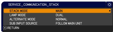
text_image
SERVICE_COMMUNICATION_STACK STACK MODE MAIN LAMP MODE DUAL ALTERNATE MODE NORMAL SUB INPUT SOURCE FOLLOW MAIN UNIT C:RETURN-
Check the STACK MODE setting in the STACK menu.
-
If MAIN is displayed, the Main projector is operating. Go to 5.4 Setting the menu.
- If SUB is displayed, the Main projector is turned off and the Sub projector is operating. Go to 5.3 Starting up Main projector.
5.3 Starting up Main projector
After performing section 5.2 Checking Main projector's operating status, the two projectors are confirmed to have been set to ALTERNATE mode and the Sub projector is currently operating. As the settings for Intellectual Stack can be changed only when the Main projector is operating, this section explains how to switch from the Sub projector to the Main projector.
- Use the ▲/▼/◄/► buttons to go into the following menu.
ADVANCED MENU > OPTION
> SERVICE > COMMUNICATION > STACK
STACK menu will appear on screen. (Operating Guide → OPTION menu)
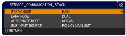
text_image
SERVICE_COMMUNICATION_STACK STACK MODE MAIN LAMP MODE DUAL ALTERNATE MODE NORMAL SUB INPUT SOURCE FOLLOW MAIN UNIT :RETURN- Check the ALTERNATE MODE setting in the menu.
If NORMAL is displayed, the two projectors are turned on alternately. Therefore, the Main projector will be turned on if you restart the projectors.
(1) Press the STANDBY/ON button on the remote control or control panel of the Main projector, the Sub projector will turn off.
(2) After the projector has cooled down, press the STANDBY/ON button to turn on again. The Main projector will be turned on.
If AUTO is displayed, the projector with the least lamp usage is turned on. Therefore, the Main projector may not be turned on even if you restart the projectors. Follow the procedures below to turn on the Main projector.
(1) Use the ▲/▼ button to highlight STACK MODE, and press the ▶ button to display the STACK MODE dialog.
(2) Use the ▲/▼ button to highlight OFF, and then press the ▶ button to complete the setting.
(3) Repeat the above procedures to display the STACK MODE dialog again.
(4) Use the ▲/▼ button to highlight SUB, and then press the ▶ button to complete the setting.
(5) After exiting the menu, wait for 10 seconds or more.
(6) Press the STANDBY/ON button on the remote control or control panel of the Main projector, the Sub projector will turn off.
(7) After the projector has cooled down, press the STANDBY/ON button to turn on again. The Main projector will be turned on even if LAMP MODE has been set to AUTO.
- You can change the settings for Intellectual Stack now that the Main projector is operating. Go to 5.4 Setting the menu.
NOTE • If the Main projector cannot be turned on due to error or certain problems, the Sub projector will be turned on even if you follow the procedures above. Take necessary actions to fix the Main projector, and then change the settings for Intellectual Stack.
5.4 Setting the menu
If Intellectual Stack with RS-232C connection is used, observe the followings.
When inputting image signals to Sub via Main, the operations differ between using computer signals and video signals such as component and video signals.
Inputting image from Main to Sub - Computer signal
- If the STACK menu is already displayed on the screen, proceed to 3 below. Otherwise press the MENU button on the remote control.
If the MENU dialog is displayed, use the ▲/▼ buttons to highlight MAIN, and press the ▶ button. A menu will be displayed.

text_image
MENU MAIN SUB :EXIT , :OKIf the MENU dialog is not displayed, the STACK menu will appear.
- Use the ▲/▼/◄/► buttons to go into the following menu.
ADVANCED MENU > OPTION
SERVICE > COMMUNICATION > STACK
STACK menu will appear on screen. (Operating Guide → OPTION menu)
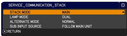
text_image
SERVICE_COMMUNICATION_STACK STACK MODE MAIN LAMP MODE DUAL ALTERNATE MODE NORMAL SUB INPUT SOURCE FOLLOW MAIN UNIT ●:RETURN- Use the ▲/▼ buttons to highlight SUB INPUT SOURCE, and press the ▶ button to display the SUB INPUT SOURCE dialog.

text_image
SUB INPUT SOURCE FOLLOW MAIN UNIT FIXED (COMPUTER IN 1) RETURN , EXIT-
Use the ▲/▼ buttons to highlight FIXED (COMPUTER IN 1), and press the ▶ button to complete the setting.
-
Press the COMPUTER or VIDEO button on the remote control or the INPUT button on the control panel of the Main projector, the MAIN INPUT SOURCE dialog is displayed on screen. Use the ▲/▼ buttons to highlight the port to which the signal cable is connected, and press the ▶ button to complete the setting.
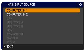
text_image
MAIN INPUT SOURCE COMPUTER IN 1 COMPUTER IN 2 LAN USB TYPE A USB TYPE B HDMI COMPONENT S-VIDEO VIDEO EXITNOTE • When FIXED (COMPUTER IN 1) is selected, the MONITOR OUT setting is invalid. (Operating Guide → SETUP menu)
- When FIXED (COMPUTER IN 1) is selected, input sources other than COMPUTER IN1 and COMPUTER IN2 cannot be selected.
- When FIXED (COMPUTER IN 1) is selected, if any button for setting the input ports including COMPUTER, VIDEO, MY SOURCE/DOC.CAMERA and MY BUTTON (assigned with input source related functions) buttons on the remote control and the INPUT button on the projector is pressed, the dialog for selecting the input source will be displayed.
Inputting image from Main to Sub
- Video signal (either component or video)
-
If the STACK menu is already displayed on the screen, proceed to 3 below. Otherwise press the MENU button on the remote control.
If the MENU dialog is displayed, use the ▲/▼ buttons to highlight MAIN, and press the ▶ button. A menu will be displayed.
If the MENU dialog is not displayed, the STACK menu will appear. -
Press the MENU button on the remote control or control panel on the Main projector. Use the ▲/▼/◄/► buttons to open the COMPUTER IN dialog. (Operating Guide → INPUT menu)
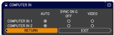
text_image
COMPUTER IN AUTO SYNC ON G OFF VIDEO COMPUTER IN 1 O O O COMPUTER IN 2 O O O RETURN EXIT- To input component signals to COMPUTER IN1 or IN2, set the port to AUTO. Then, use the ▲/▼/◄/► buttons to highlight EXIT and press the ► button to complete the setting.
To input video signals to COMPUTER IN1 or IN2, set the port to VIDEO. If it is necessary to select a video format, use the ▲/▼/◄/► buttons to highlight RETURN and press the ◀ button to display the INPUT menu. Otherwise, use the ▲/▼/◄/► buttons to highlight EXIT and press the ► button to complete the setting.
- Select VIDEO FORMAT in the INPUT menu to display the VIDEO FORMAT dialog.
Select AUTO or an appropriate format for the video signal input.
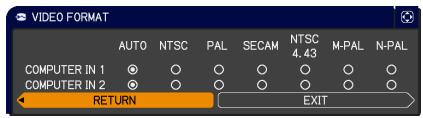
Then, use the ▲/▼/◄/► buttons to highlight EXIT and press the ► button to complete the setting.
Inputting image to Sub and Main individually
-
If the STACK menu is already displayed on the screen, proceed to 3 below. Otherwise press the MENU button on the remote control.
If the MENU dialog is displayed, use the ▲/▼ buttons to highlight MAIN, and press the ▶ button. A menu will be displayed.
If the MENU dialog is not displayed, the STACK menu will appear. -
Use the ▲/▼/◄/► buttons to go into the following menu.
ADVANCED MENU > OPTION
SERVICE > COMMUNICATION > STACK
STACK menu will appear on screen. (Operating Guide → OPTION menu)
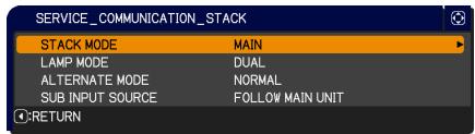
text_image
SERVICE_COMMUNICATION_STACK STACK MODE MAIN LAMP MODE DUAL ALTERNATE MODE NORMAL SUB INPUT SOURCE FOLLOW MAIN UNIT RETURN(continued on next page)
5.4 Setting the menu - Inputting image to Sub and Main individually (continued)
- Use the ▲/▼ buttons to highlight SUB INPUT SOURCE, and press the ▶ button to display the SUB INPUT SOURCE dialog.
- Use the ▲/▼ buttons to highlight FOLLOW MAIN UNIT, and press the ▶ button to complete the setting.
- Press the COMPUTER or VIDEO button on the remote control or the INPUT button on the control panel of the Main projector, the MAIN INPUT SOURCE dialog is displayed on screen. Use the ▲/▼ buttons to highlight the port to which the signal cable is connected, and press the ▶ button to complete the setting.

text_image
SUB INPUT SOURCE FOLLOW MAIN UNIT FIXED (COMPUTER IN 1) :RETURN , :EXIT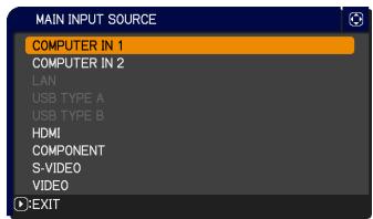
text_image
MAIN INPUT SOURCE COMPUTER IN 1 COMPUTER IN 2 LAN USB TYPE A USB TYPE B HDMI COMPONENT S-VIDEO VIDEO EXITNOTE • If FOLLOW MAIN UNIT is selected, selecting the input source on either the Main or Sub projector will automatically set the other projector to the same source.
- If FOLLOW MAIN UNIT is selected, LAN, USB TYPE A and USB TYPE B cannot be selected.
- When FOLLOW MAIN UNIT is selected, if any button for setting the input ports including COMPUTER, VIDEO, MY SOURCE/DOC.CAMERA and MY BUTTON (assigned with input source related functions) buttons on the remote control and the INPUT button on the projector is pressed, the dialog for selecting the input source will be displayed.
6. Restrictions on Schedule function
This model supports the Schedule function on the Web Control feature. (Network Guide → 3. Web Control → 3.7 Schedule Settings) There are some restrictions on the functions when Intellectual Stack with RS-232C connection is used. But for Simple Stack without an RS-232C connection, there is no restriction on the functions.
Regardless of whether Intellectual Stack or Simple Stack is used, take note of the Schedule settings before using the Stack function. Unexpected setting changes may occur when using the Stack function.
Refer to the following for the restrictions concerning Intellectual Stack. If you are using Simple Stack, skip this chapter.
Restrictions on the Main projector
| Functions | LAMP MODE | |||||
| DUAL | ALTERNATE | DUAL/ ALTERNATE | ||||
| Power status | Main | ON | ON | OFF | OFF | |
| Sub | ON | OFF | ON | OFF | ||
| Power On | ✓ | ✓ | ✓ | ✓ | ||
| Power Off | ✓ | ✓ | ✓ | ✓ | ||
| Input port change | ✓ *1) | ✓ *1) | ✓ *1) | ✓ *1) | ||
| My Image | ✓ | ✓ | X *2) | X *2) | ||
| Messenger | ✓ | ✓ | X *2) | X *2) | ||
| Slide Show | X *3) | X *3) | X *3) | X *3) | ||
Restrictions on the Sub projector
| Functions | LAMP MODE | |||||
| DUAL | ALTERNATE | DUAL/ ALTERNATE | ||||
| Power status | Main | ON | ON | OFF | OFF | |
| Sub | ON | OFF | ON | OFF | ||
| Power On | X *3 | X *3 | X *3 | X *3 | ||
| Power Off | ✓ | ✓ | ✓ | ✓ | ||
| Input port change | ✓ *1) | ✓ *1) | ✓ *1) | ✓ *1) | ||
| My Image | ✓ | X *2) | ✓ | X *2) | ||
| Messenger | ✓ | X *2) | ✓ | X *2) | ||
| Slide Show | X *3) | X *3) | X *3) | X *3) | ||
√ : This Schedule can be input to Web Control and be executed even if the projectors are operating in Intellectual Stack.
√ *1): This Schedule can be input to Web Control even if the projectors are
(continued on next page)
6. Restrictions on Schedule function (continued)
operating in Intellectual Stack. If the input port to be changed according to the Schedule function can be used in Intellectual Stack, the Schedule will be executed. If not, it will not be executed.
X *2): This Schedule can be input to Web Control when the projectors are operating in Intellectual Stack but it will not be executed.
X *3): This Schedule can neither be input to Web Control nor be executed when the projectors are operating in Intellectual Stack.
NOTE • If the Schedule is not executed, an error message will be sent in accordance with the conditions set in Schedule Execution Error on Web Control. (Network Guide → 3. Web Control → 3.6 Alert Settings)
- If the Schedule function is set to turn off the power when the projectors are operating in Intellectual Stack, both the Main and Sub projectors will be turned off.
- If the Schedule function on the Main projector is set to turn on the power, the projectors will be turned on according to the LAMP MODE setting.
- When the two projectors are operating in the DUAL mode and a menu is being displayed on one of the projectors, the Schedule function for My Image and Messenger on the other projector will not be executed.
- Power Off in the table refers to turning off the power and entering into standby mode according to the Intellectual Stack settings or by pressing the STANDBY/ON button on the remote control or control panel of the Main projector.
- The projectors cannot be turned on by the Schedule function on the Sub projector. Set it on the Main projector if necessary.
- When the Sub projector is turned off according to the ALTERNATE MODE setting, the Schedule function on the Sub projector to turn off its power will be executed without error.
7. Troubleshooting
About the phenomenon confused with a machine defect, check and cope with it according to the following table.
Phenomena that may be easy to be mistaken for machine defects
| Phenomenon | Cases not involving a machine defect | Reference page |
| Intellectual Stack does not function. | No power is supplied to the Main and Sub projector.To use the Intellectual Stack feature, supply AC power to both the Main and Sub projectors. If AC power is supplied to only one of the projectors, Intellectual Stack is disabled. | 8in User's Manual (concise) |
| The RS-232C cable between the Main and Sub projectors is not properly connected.To use the Intellectual Stack feature, connect an RS-232C cross cable between the Main and Sub projectors. If the cable is not connected, the Main projector cannot control the Sub projector. | 11 | |
| The menu settings for Intellectual Stack are not performed correctly.Check the settings of the STACK menu on the Main and Sub projectors. To use the Intellectual Stack feature, one projector must be set to Main and the other projector must be set to Sub. | 18 | |
| Signal cables are not connected correctly.Check the connection of cables. Also check that the cable connection matches with the port settings in the menu. | 2810 - 14in Operating Guide | |
| The Main and Sub projector do not operate in synchronization. | The RS-232C cable between the Main and Sub projectors is not properly connected.Connect the RS-232C cable properly and restart the Main projector. | 11 |
| The STACK menu cannot function. | The settings on the projectors are not set for the Intellectual Stack feature.Check the following settings on the Main and Sub projectors.- STANDBY MODE in SETUP menu: NORMAL- COMMUNICATION TYPE under COMMUNICATION in SERVICE menu: OFF- STACK LOCK in SECURITY menu: OFF | 7 |
| The projector does not respond to the remote control. | The remote control is pointed at the Sub projector.When operating in Intellectual Stack, only the Main projector is capable of receiving the remote control signals. Therefore, point at the Main projector when using the remote control. | 6 |
| The images are either out of focus or not well-superimposed. | The two images are not superimposed correctly.Adjust the ZOOM ring, VERTICAL adjuster, HORIZONTAL adjuster and the FOCUS ring to superimpose the images.If necessary, adjust PERFECT FIT and KEYSTONE as well. | 815 |
| The images from the two projectors do not superimposed even after performing fine adjustment. | There are some adjustment differences in the two images.Try to resolve the problem with the following measures.- Press the AUTO button on the remote control or execute AUTO ADJUST EXECUTE on each of the projectors.- Adjust H POSITION and V POSITION on each of the projectors.- Check the RESOLUTION setting in the INPUT menu, and change to the same setting if the setting differs between Main and Sub. | 24in Operating Guide38in Operating Guide42in Operating Guide |
End User License Agreement for the Projector Software
Software in the projector consists of the plural number of independent software modules and there exist our copyright or/and third party copyrights for each of such software modules. The projector also uses software modules that we have developed or/and produced. And there exist our copyright and intellectual property for each of such software and related items including but not limited to the software related documents.
These rights above are protected by copyright law and other applicable laws. And the projector uses software modules licensed as Freeware upon GNU GENERAL PUBLIC LICENSE Version 2 and GNU LESSER GENERAL PUBLIC LICENSE Version 2.1 established by Free Software Foundation, Inc. (U.S.) or license agreements for each software.
Refer following web page for license agreements for such software modules and other software.
web page address: http://www.viewsonic.com/products/pro9500.htm
Contact dealer in your region for inquiry regarding licensed software. Refer to license agreement of each software in following pages and license agreements of each software on the web page for detail of the license conditions and so on. (The original in English is carried since the license agreement following is established by third party other than us.)
Because the program (the software module) is licensed free of charge, the program is provided "as is" without warranty of any kind, either expressed or implied, to the extent permitted by applicable law. And we do not take any responsibility or compensate for loss of any kind (including but not limited to loss of data, loss of accuracy or loss of compatibility with interface between other programs) by the software concerned or/and use of the software concerned to the extent permitted by applicable law.
URL: http://www.viewsonic.com/products/pro9500.htm
Webadresse: http://www.viewsonic.com/products/pro9500.htm
Webpagina: http://www.viewsonic.com/products/pro9500.htm
GNU GENERAL PUBLIC LICENSE Version 2, June 1991
Copyright © 1989, 1991 Free Software Foundation, Inc.
51 Franklin St, Fifth Floor, Boston, MA 02110-1301 USA
Everyone is permitted to copy and distribute verbatim copies of this license document, but changing it is not allowed.
Preamble
The licenses for most software are designed to take away your freedom to share and change it. By contrast, the GNU General Public License is intended to guarantee your freedom to share and change free software—to make sure the software is free for all its users. This General Public License applies to most of the Free Software Foundation's software and to any other program whose authors commit to using it. (Some other Free Software Foundation software is covered by the GNU Library General Public License instead.) You can apply it to your programs, too.
When we speak of free software, we are referring to freedom, not price. Our General Public Licenses are designed to make sure that you have the freedom to distribute copies of free software (and charge for this service if you wish), that you receive source code or can get it if you want it, that you can change the software or use pieces of it in new free programs; and that you know you can do these things.
To protect your rights, we need to make restrictions that forbid anyone to deny you these rights or to ask you to surrender the rights. These restrictions translate to certain responsibilities for you if you distribute copies of the software, or if you modify it.
For example, if you distribute copies of such a program, whether gratis or for a fee, you must give the recipients all the rights that you have. You must make sure that they, too, receive or can get the source code. And you must show them these terms so they know their rights.
We protect your rights with two steps: (1) copyright the software, and (2) offer you this license which gives you legal permission to copy, distribute and/or modify the software.
Also, for each author's protection and ours, we want to make certain that everyone understands that there is no warranty for this free software. If the software is modified by someone else and passed on, we want its recipients to know that what they have is not the original, so that any problems introduced by others will not reflect on the original authors' reputations.
Finally, any free program is threatened constantly by software patents. We wish to avoid the danger that redistributors of a free program will individually obtain patent licenses, in effect making the program proprietary. To prevent this, we have made it clear that any patent must be licensed for everyone's free use or not licensed at all.
The precise terms and conditions for copying, distribution and modification follow.
GNU GENERAL PUBLIC LICENSE TERMS AND CONDITIONS FOR COPYING, DISTRIBUTION AND MODIFICATION
- This License applies to any program or other work which contains a notice placed by the copyright holder saying it may be distributed under the terms of this General Public License. The "Program", below, refers to any such program or work, and a "work based on the Program" means either the Program or any derivative work under copyright law: that is to say, a work containing the Program or a portion of it, either verbatim or with modifications and/or translated into another language.
(Hereinafter, translation is included without limitation in the term
"modification".) Each licensee is addressed as "you".
Activities other than copying, distribution and modification are not covered by this License; they are outside its scope. The act of running the Program is not restricted, and the output from the Program is covered only if its contents constitute a work based on the Program (independent of having been made by running the Program). Whether that is true depends on what the Program does.
- You may copy and distribute verbatim copies of the Program's source code as you receive it, in any medium, provided that you conspicuously and appropriately publish on each copy an appropriate copyright notice and disclaimer of warranty; keep intact all the notices that refer to this License and to the absence of any warranty; and give any other recipients of the Program a copy of this License along with the Program.
You may charge a fee for the physical act of transferring a copy, and you may at your option offer warranty protection in exchange for a fee.
- You may modify your copy or copies of the Program or any portion of it, thus forming a work based on the Program, and copy and distribute such modifications or work under the terms of Section 1 above, provided that you also meet all of these conditions:
a) You must cause the modified files to carry prominent notices stating that you changed the files and the date of any change.
b) You must cause any work that you distribute or publish, that in whole or in part contains or is derived from the Program or any part thereof, to be licensed as a whole at no charge to all third parties under the terms of this License.
c) If the modified program normally reads commands interactively when run, you must cause it, when started running for such interactive use in the most ordinary way, to print or display an announcement including an appropriate copyright notice and a notice that there is no warranty (or else, saying that you provide a warranty) and that users may redistribute the program under these conditions, and telling the user how to view a copy of this License. (Exception: if the Program itself is interactive but does not normally print such an announcement, your work based on the Program is not required to print an announcement.)
These requirements apply to the modified work as a whole. If identifiable sections of that work are not derived from the Program, and can be reasonably considered independent and separate works in themselves, then this License, and its terms, do not apply to those sections when you distribute them as separate works. But when you distribute the same sections as part of a whole which is a work based on the Program, the distribution of the whole must be on the terms of this License, whose permissions for other licensees extend to the entire whole, and thus to each and every part regardless of who wrote it.
Thus, it is not the intent of this section to claim rights or contest your rights to work written entirely by you; rather, the intent is to exercise the right to control the distribution of derivative or collective works based on the Program.
In addition, mere aggregation of another work not based on the Program with the Program (or with a work based on the Program) on a volume of a storage or distribution medium does not bring the
other work under the scope of this License.
- You may copy and distribute the Program (or a work based on it, under Section 2) in object code or executable form under the terms of Sections 1 and 2 above provided that you also do one of the following:
a) Accompany it with the complete corresponding machinereadable source code, which must be distributed under the terms of Sections 1 and 2 above on a medium customarily used for software interchange; or,
b) Accompany it with a written offer, valid for at least three years, to give any third party, for a charge no more than your cost of physically performing source distribution, a complete machine-readable copy of the corresponding source code, to be distributed under the terms of Sections 1 and 2 above on a medium customarily used for software interchange; or,
c) Accompany it with the information you received as to the offer to distribute corresponding source code. (This alternative is allowed only for noncommercial distribution and only if you received the program in object code or executable form with such an offer, in accord with Subsection b above.)
The source code for a work means the preferred form of the work for making modifications to it. For an executable work, complete source code means all the source code for all modules it contains, plus any associated interface definition files, plus the scripts used to control compilation and installation of the executable. However, as a special exception, the source code distributed need not include anything that is normally distributed (in either source or binary form) with the major components (compiler, kernel, and so on) of the operating system on which the executable runs, unless that component itself accompanies the executable.
If distribution of executable or object code is made by offering access to copy from a designated place, then offering equivalent access to copy the source code from the same place counts as distribution of the source code, even though third parties are not compelled to copy the source along with the object code.
- You may not copy, modify, sublicense, or distribute the Program except as expressly provided under this License. Any attempt otherwise to copy, modify, sublicense or distribute the Program is void, and will automatically terminate your rights under this License. However, parties who have received copies, or rights, from you under this License will not have their licenses terminated so long as such parties remain in full compliance.
- You are not required to accept this License, since you have not signed it. However, nothing else grants you permission to modify or distribute the Program or its derivative works. These actions are prohibited by law if you do not accept this License. Therefore, by modifying or distributing the Program (or any work based on the Program), you indicate your acceptance of this License to do so, and all its terms and conditions for copying, distributing or modifying the Program or works based on it.
- Each time you redistribute the Program (or any work based on the Program), the recipient automatically receives a license from the original licensor to copy, distribute or modify the Program subject to these terms and conditions. You may not impose any further restrictions on the recipients' exercise of the rights granted herein. You are not responsible for enforcing compliance by third parties to this License.
- If, as a consequence of a court judgment or allegation of patent infringement or for any other reason (not limited to patent issues), conditions are imposed on you (whether by court order, agreement or otherwise) that contradict the conditions of this License, they do not excuse you from the conditions of this License. If you
cannot distribute so as to satisfy simultaneously your obligations under this License and any other pertinent obligations, then as a consequence you may not distribute the Program at all.
For example, if a patent license would not permit royalty-free redistribution of the Program by all those who receive copies directly or indirectly through you, then the only way you could satisfy both it and this License would be torefrain entirely from distribution of the Program. If any portion of this section is held invalid or unenforceable underany particular circumstance, the balance of the section is intended toapply and the section as a whole is intended to apply in othercircumstances.
It is not the purpose of this section to induce you to infringe any patents or other property right claims or to contest validity of any such claims; this section has the sole purpose of protecting the integrity of the free software distribution system, which is implemented by public license practices. Many people have made generous contributions to the wide range of software distributed through that system in reliance on consistent application of that system; it is up to the author/donor to decide if he or she is willing to distribute software through any other system and a licensee cannot impose that choice.
This section is intended to make thoroughly clear what is believed to be a consequence of the rest of this License.
- If the distribution and/or use of the Program is restricted in certain countries either by patents or by copyrighted interfaces, the original copyright holder who places the Program under this License may add an explicit geographical distribution limitation excluding those countries, so that distribution is permitted only in or among countries not thus excluded. In such case, this License incorporates the limitation as if written in the body of this License.
- The Free Software Foundation may publish revised and/or new versions of the General Public License from time to time. Such new versions will be similar in spirit to the present version, but may differ in detail to address new problems or concerns.
Each version is given a distinguishing version number. If the Program specifies a version number of this License which applies to it and "any later version", you have the option of following the terms and conditions either of that version or of any later version published by the Free Software Foundation. If the Program does not specify a version number of this License, you may choose any version ever published by the Free Software Foundation.
- If you wish to incorporate parts of the Program into other free programs whose distribution conditions are different, write to the author to ask for permission. For software which is copyrighted by the Free Software Foundation, write to the Free Software Foundation; we sometimes make exceptions for this. Our decision will be guided by the two goals of preserving the free status of all derivatives of our free software and of promoting the sharing and reuse of software generally.
NO WARRANTY
-
BECAUSE THE PROGRAM IS LICENSED FREE OF CHARGE, THERE IS NO WARRANTY FOR THE PROGRAM, TO THE EXTENT PERMITTED BY APPLICABLE LAW. EXCEPT WHEN OTHERWISE STATED IN WRITING THE COPYRIGHT HOLDERS AND/OR OTHER PARTIES PROVIDE THE PROGRAM "AS IS" WITHOUT WARRANTY OF ANY KIND, EITHER EXPRESSED OR IMPLIED, INCLUDING, BUT NOT LIMITED TO, THE IMPLIED WARRANTIES OF MERCHANTABILITY AND FITNESS FOR A PARTICULAR PURPOSE. THE ENTIRE RISK AS TO THE QUALITY AND PERFORMANCE OF THE PROGRAM IS WITH YOU. SHOULD THE PROGRAM PROVE DEFECTIVE, YOU ASSUME THE COST OF ALL NECESSARY SERVICING, REPAIR OR CORRECTION.
-
IN NO EVENT UNLESS REQUIRED BY APPLICABLE LAW OR AGREED TO IN WRITING WILL ANY COPYRIGHT HOLDER, OR ANY OTHER PARTY WHO MAY MODIFY AND/OR REDISTRIBUTE THE PROGRAM AS PERMITTED ABOVE, BE LIABLE TO YOU FOR DAMAGES, INCLUDING ANY GENERAL, SPECIAL, INCIDENTAL OR CONSEQUENTIAL DAMAGES ARISING OUT OF THE USE OR INABILITY TO USE THE PROGRAM (INCLUDING BUT NOT LIMITED TO LOSS OF DATA OR DATA BEING RENDERED INACCURATE OR LOSSES SUSTAINED BY YOU OR THIRD PARTIES OR A FAILURE OF THE PROGRAM TO OPERATE WITH ANY OTHER PROGRAMS), EVEN IF SUCH HOLDER OR OTHER PARTY HAS BEEN ADVISED OF THE POSSIBILITY OF SUCH DAMAGES.
END OF TERMS AND CONDITIONS
How to Apply These Terms to Your New Programs
If you develop a new program, and you want it to be of the greatest possible use to the public, the best way to achieve this is to make it free software which everyone can redistribute and change under these terms.
To do so, attach the following notices to the program. It is safest to attach them to the start of each source file to most effectively convey the exclusion of warranty; and each file should have at least the "copyright" line and a pointer to where the full notice is found.
Copyright ©
This program is free software; you can redistribute it and/or modify it under the terms of the GNU General Public License as published by the Free Software Foundation; either version 2 of the License, or (at your option) any later version.
This program is distributed in the hope that it will be useful, but WITHOUT ANY WARRANTY; without even the implied warranty of MERCHANTABILITY or FITNESS FOR A PARTICULAR PURPOSE. See the GNU General Public License for more details.
You should have received a copy of the GNU General Public License along with this program; if not, write to the Free Software Foundation, Inc., 51 Franklin St, Fifth Floor, Boston,
MA 02110-1301 USA
Also add information on how to contact you by electronic and paper mail.
If the program is interactive, make it output a short notice like this when it starts in an interactive mode:
Gnomovision version 69, Copyright © year name of author Gnomovision comes with ABSOLUTELY NO WARRANTY; for details type 'show w'. This is free software, and you are welcome to redistribute it under certain conditions; type 'show c' for details.
The hypothetical commands `show w' and `show c' should show the appropriate parts of the General Public License. Of course, the commands you use may be called something other than `show w' and `show c'; they could even be mouse-clicks or menu items-- whatever suits your program.
You should also get your employer (if you work as a programmer) or your school, if any, to sign a "copyright disclaimer" for the program, if necessary. Here is a sample; alter the names:
Yoyodyne, Inc., hereby disclaims all copyright interest in the
program `Gnomovision' (which makes passes at compilers) written by James Hacker.
Ty Coon, President of Vice
This General Public License does not permit incorporating your program into proprietary programs. If your program is a subroutine library, you may consider it more useful to permit linking proprietary applications with the library. If this is what you want to do, use the GNU Library General Public License instead of this License.
GNU LESSER GENERAL PUBLIC LICENSE Version 2.1, February 1999
Copyright © 1991, 1999 Free Software Foundation, Inc. 51 Franklin St, Fifth Floor, Boston, MA 02110-1301 USA Everyone is permitted to copy and distribute verbatim copies of this license document, but changing it is not allowed.
[This is the first released version of the Lesser GPL. It also counts as the successor of the GNU Library Public License, version 2, hence the version number 2.1.]
Preamble
The licenses for most software are designed to take away your freedom to share and change it. By contrast, the GNU General Public Licenses are intended to guarantee your freedom to share and change free software--to make sure the software is free for all its users.
This license, the Lesser General Public License, applies to some specially designated software packages—typically libraries—of the Free Software Foundation and other authors who decide to use it. You can use it too, but we suggest you first think carefully about whether this license or the ordinary General Public License is the better strategy to use in any particular case, based on the explanations below.
When we speak of free software, we are referring to freedom of use, not price. Our General Public Licenses are designed to make sure that you have the freedom to distribute copies of free software (and charge for this service if you wish); that you receive source code or can get it if you want it; that you can change the software and use pieces of it in new free programs; and that you are informed that you can do these things.
To protect your rights, we need to make restrictions that forbid distributors to deny you these rights or to ask you to surrender these rights. These restrictions translate to certain responsibilities for you if you distribute copies of the library or if you modify it.
For example, if you distribute copies of the library, whether gratis or for a fee, you must give the recipients all the rights that we gave you. You must make sure that they, too, receive or can get the source code. If you link other code with the library, you must provide complete object files to the recipients, so that they can relink them with the library after making changes to the library and recompiling it. And you must show them these terms so they know their rights.
We protect your rights with a two-step method: (1) we copyright the library, and (2) we offer you this license, which gives you legal permission to copy, distribute and/or modify the library.
To protect each distributor, we want to make it very clear that there is no warranty for the free library. Also, if the library is modified by someone else and passed on, the recipients should know that what they have is not the original version, so that the original author's reputation will not be affected by problems that might be introduced by others.
Finally, software patents pose a constant threat to the existence of any free program. We wish to make sure that a company cannot effectively restrict the users of a free program by obtaining a restrictive license from a patent holder. Therefore, we insist that any patent license obtained for a version of the library must be consistent with the full freedom of use specified in this license.
Most GNU software, including some libraries, is covered by the ordinary GNU General Public License. This license, the GNU Lesser General Public License, applies to certain designated libraries, and is quite different from the ordinary General Public License. We use this license for certain libraries in order to permit linking those libraries into non-free programs.
When a program is linked with a library, whether statically or using a shared library, the combination of the two is legally speaking a combined work, a derivative of the original library. The ordinary General Public License therefore permits such linking only if the entire combination fits its criteria of freedom. The Lesser General Public License permits more lax criteria for linking other code with the library.
We call this license the "Lesser" General Public License because it does Less to protect the user's freedom than the ordinary General Public License. It also provides other free software developers Less of an advantage over competing non-free programs. These disadvantages are the reason we use the ordinary General Public License for many libraries. However, the Lesser license provides advantages in certain special circumstances.
For example, on rare occasions, there may be a special need to encourage the widest possible use of a certain library, so that it becomes a de-facto standard. To achieve this, non-free programs must be allowed to use the library. A more frequent case is that a free library does the same job as widely used non-free libraries. In this case, there is little to gain by limiting the free library to free software only, so we use the Lesser General Public License.
In other cases, permission to use a particular library in non-free programs enables a greater number of people to use a large body of free software. For example, permission to use the GNU C Library in non-free programs enables many more people to use the whole GNU operating system, as well as its variant, the GNU/Linux operating system.
Although the Lesser General Public License is Less protective of the users' freedom, it does ensure that the user of a program that is linked with the Library has the freedom and the wherewithal to run that program using a modified version of the Library.
The precise terms and conditions for copying, distribution and modification follow. Pay close attention to the difference between a "work based on the library" and a "work that uses the library". The former contains code derived from the library, whereas the latter must be combined with the library in order to run.
GNU LESSER GENERAL PUBLIC LICENSE TERMS AND CONDITIONS FOR COPYING, DISTRIBUTION AND MODIFICATION
- This License Agreement applies to any software library or other program which contains a notice placed by the copyright holder or other authorized party saying it may be distributed under the terms of this Lesser General Public License (also called "this License"). Each licensee is addressed as "you".
A "library" means a collection of software functions and/or data prepared so as to be conveniently linked with application programs (which use some of those functions and data) to form executables.
The "Library", below, refers to any such software library or work which has been distributed under these terms. A "work based on the Library" means either the Library or any derivative work under copyright law: that is to say, a work containing the Library or a portion of it, either verbatim or with modifications and/or translated straightforwardly into another language. (Hereinafter, translation is included without limitation in the term "modification".)
"Source code" for a work means the preferred form of the work for making modifications to it. For a library, complete source code
means all the source code for all modules it contains, plus any associated interface definition files, plus the scripts used to control compilation and installation of the library.
Activities other than copying, distribution and modification are not covered by this License; they are outside its scope. The act of running a program using the Library is not restricted, and output from such a program is covered only if its contents constitute a work based on the Library (independent of the use of the Library in a tool for writing it). Whether that is true depends on what the Library does and what the program that uses the Library does.
- You may copy and distribute verbatim copies of the Library's complete source code as you receive it, in any medium, provided that you conspicuously and appropriately publish on each copy an appropriate copyright notice and disclaimer of warranty; keep intact all the notices that refer to this License and to the absence of any warranty; and distribute a copy of this License along with the Library
You may charge a fee for the physical act of transferring a copy, and you may at your option offer warranty protection in exchange for a fee.
- You may modify your copy or copies of the Library or any portion of it, thus forming a work based on the Library, and copy and distribute such modifications or work under the terms of Section 1 above, provided that you also meet all of these conditions:
a) The modified work must itself be a software library.
b) You must cause the files modified to carry prominent notices stating that you changed the files and the date of any change.
c) You must cause the whole of the work to be licensed at no charge to all third parties under the terms of this License.
d) If a facility in the modified Library refers to a function or a table of data to be supplied by an application program that uses the facility, other than as an argument passed when the facility is invoked, then you must make a good faith effort to ensure that, in the event an application does not supply such function or table, the facility still operates, and performs whatever part of its purpose remains meaningful. (For example, a function in a library to compute square roots has a purpose that is entirely well-defined independent of the application. Therefore, Subsection 2d requires that any application-supplied function or table used by this function must be optional: if the application does not supply it, the square root function must still compute square roots.)
These requirements apply to the modified work as a whole. If dentifiable sections of that work are not derived from the Library, and can be reasonably considered independent and separate works in themselves, then this License, and its terms, do not apply to those sections when you distribute them as separate works. But when you distribute the same sections as part of a whole which is a work based on the Library, the distribution of the whole must be on the terms of this License, whose permissions for other licensees extend to the entire whole, and thus to each and every part regardless of who wrote it.
Thus, it is not the intent of this section to claim rights or contest your rights to work written entirely by you; rather, the intent is to exercise the right to control the distribution of derivative or collective works based on the Library.
In addition, mere aggregation of another work not based on the Library with the Library (or with a work based on the Library) on a volume of a storage or distribution medium does not bring the other work under the scope of this License.
- You may opt to apply the terms of the ordinary GNU General
Public License instead of this License to a given copy of the Library. To do this, you must alter all the notices that refer to this License, so that they refer to the ordinary GNU General Public License, version 2, instead of to this License. (If a newer version than version 2 of the ordinary GNU General Public License has appeared, then you can specify that version instead if you wish.) Do not make any other change in these notices.
Once this change is made in a given copy, it is irreversible for that copy, so the ordinary GNU General Public License applies to all subsequent copies and derivative works made from that copy.
This option is useful when you wish to copy part of the code of the Library into a program that is not a library.
- You may copy and distribute the Library (or a portion or derivative of it, under Section 2) in object code or executable form under the terms of Sections 1 and 2 above provided that you accompany it with the complete corresponding machine-readable source code, which must be distributed under the terms of Sections 1 and 2 above on a medium customarily used for software interchange.
If distribution of object code is made by offering access to copy from a designated place, then offering equivalent access to copy the source code from the same place satisfies the requirement to distribute the source code, even though third parties are not compelled to copy the source along with the object code.
- A program that contains no derivative of any portion of the Library, but is designed to work with the Library by being compiled or linked with it, is called a "work that uses the Library". Such a work, in isolation, is not a derivative work of the Library, and therefore falls outside the scope of this License.
However, linking a "work that uses the Library" with the Library creates an executable that is a derivative of the Library (because it contains portions of the Library), rather than a "work that uses the library". The executable is therefore covered by this License. Section 6 states terms for distribution of such executables.
When a "work that uses the Library" uses material from a header file that is part of the Library, the object code for the work may be a derivative work of the Library even though the source code is not. Whether this is true is especially significant if the work can be linked without the Library, or if the work is itself a library. The threshold for this to be true is not precisely defined by law.
If such an object file uses only numerical parameters, data structure layouts and accessors, and small macros and small inline functions (ten lines or less in length), then the use of the object file is unrestricted, regardless of whether it is legally a derivative work. (Executables containing this object code plus portions of the Library will still fall under Section 6.)
Otherwise, if the work is a derivative of the Library, you may distribute the object code for the work under the terms of Section 6. Any executables containing that work also fall under Section 6, whether or not they are linked directly with the Library itself.
- As an exception to the Sections above, you may also combine or link a "work that uses the Library" with the Library to produce a work containing portions of the Library, and distribute that work under terms of your choice, provided that the terms permit modification of the work for the customer's own use and reverse engineering for debugging such modifications.
You must give prominent notice with each copy of the work that the Library is used in it and that the Library and its use are covered by this License. You must supply a copy of this License. If the work during execution displays copyright notices, you must include the copyright notice for the Library among them, as well as a reference directing the user to the copy of this License. Also, you must do one of these things:
a) Accompany the work with the complete corresponding machine-readable source code for the Library including whatever changes were used in the work (which must be distributed under Sections 1 and 2 above); and, if the work is an executable linked with the Library, with the complete machine-readable "work that uses the Library", as object code and/or source code, so that the user can modify the Library and then relink to produce a modified executable containing the modified Library. (It is understood that the user who changes the contents of definitions files in the Library will not necessarily be able to recompile the application to use the modified definitions.)
b) Use a suitable shared library mechanism for linking with the Library. A suitable mechanism is one that (1) uses at run time a copy of the library already present on the user's computer system, rather than copying library functions into the executable, and (2) will operate properly with a modified version of the library, if the user installs one, as long as the modified version is interface-compatible with the version that the work was made with.
c) Accompany the work with a written offer, valid for at least three years, to give the same user the materials specified in Subsection 6a, above, for a charge no more than the cost of performing this distribution.
d) If distribution of the work is made by offering access to copy from a designated place, offer equivalent access to copy the above specified materials from the same place.
e) Verify that the user has already received a copy of these materials or that you have already sent this user a copy.
For an executable, the required form of the "work that uses the Library" must include any data and utility programs needed for reproducing the executable from it. However, as a special exception, the materials to be distributed need not include anything that is normally distributed (in either source or binary form) with the major components (compiler, kernel, and so on) of the operating system on which the executable runs, unless that component itself accompanies the executable.
It may happen that this requirement contradicts the license restrictions of other proprietary libraries that do not normally accompany the operating system. Such a contradiction means you cannot use both them and the Library together in an executable that you distribute.
- You may place library facilities that are a work based on the Library side-by-side in a single library together with other library facilities not covered by this License, and distribute such a combined library, provided that the separate distribution of the work based on the Library and of the other library facilities is otherwise permitted, and provided that you do these two things:
a) Accompany the combined library with a copy of the same work based on the Library, uncombined with any other library facilities. This must be distributed under the terms of the Sections above.
b) Give prominent notice with the combined library of the fact that part of it is a work based on the Library, and explaining where to find the accompanying uncombined form of the same work.
-
You may not copy, modify, sublicense, link with, or distribute the Library except as expressly provided under this License. Any attempt otherwise to copy, modify, sublicense, link with, or distribute the Library is void, and will automatically terminate your rights under this License. However, parties who have received copies, or rights, from you under this License will not have their licenses terminated so long as such parties remain in full compliance.
-
You are not required to accept this License, since you have not signed it. However, nothing else grants you permission to modify or distribute the Library or its derivative works. These actions are prohibited by law if you do not accept this License. Therefore, by modifying or distributing the Library (or any work based on the Library), you indicate your acceptance of this License to do so, and all its terms and conditions for copying, distributing or modifying the Library or works based on it.
- Each time you redistribute the Library (or any work based on the Library), the recipient automatically receives a license from the original licensor to copy, distribute, link with or modify the Library subject to these terms and conditions. You may not impose any further restrictions on the recipients' exercise of the rights granted herein. You are not responsible for enforcing compliance by third parties with this License.
- If, as a consequence of a court judgment or allegation of patent infringement or for any other reason (not limited to patent issues), conditions are imposed on you (whether by court order, agreement or otherwise) that contradict the conditions of this License, they do not excuse you from the conditions of this License. If you cannot distribute so as to satisfy simultaneously your obligations under this License and any other pertinent obligations, then as a consequence you may not distribute the Library at all. For example, if a patent license would not permit royalty-free redistribution of the Library by all those who receive copies directly or indirectly through you, then the only way you could satisfy both it and this License would be to refrain entirely from distribution of the Library.
If any portion of this section is held invalid or unenforceable under any particular circumstance, the balance of the section is intended to apply, and the section as a whole is intended to apply in other circumstances.
It is not the purpose of this section to induce you to infringe any patents or other property right claims or to contest validity of any such claims; this section has the sole purpose of protecting the integrity of the free software distribution system which is implemented by public license practices. Many people have made generous contributions to the wide range of software distributed through that system in reliance on consistent application of that system; it is up to the author/donor to decide if he or she is willing to distribute software through any other system and a licensee cannot impose that choice.
This section is intended to make thoroughly clear what is believed to be a consequence of the rest of this License.
- If the distribution and/or use of the Library is restricted in certain countries either by patents or by copyrighted interfaces, the original copyright holder who places the Library under this License may add an explicit geographical distribution limitation excluding those countries, so that distribution is permitted only in or among countries not thus excluded. In such case, this License incorporates the limitation as if written in the body of this License.
- The Free Software Foundation may publish revised and/or new versions of the Lesser General Public License from time to time. Such new versions will be similar in spirit to the present version, but may differ in detail to address new problems or concerns. Each version is given a distinguishing version number. If the Library specifies a version number of this License which applies to it and "any later version", you have the option of following the terms and conditions either of that version or of any later version published by the Free Software Foundation. If the Library does not specify a license version number, you may choose any version ever published by the Free Software Foundation.
- If you wish to incorporate parts of the Library into other free programs whose distribution conditions are incompatible with these, write to the author to ask for permission. For
software which is copyrighted by the Free Software Foundation, write to the Free Software Foundation; we sometimes make exceptions for this. Our decision will be guided by the two goals of preserving the free status of all derivatives of our free software and of promoting the sharing and reuse of software generally.
NO WARRANTY
-
BECAUSE THE LIBRARY IS LICENSED FREE OF CHARGE, THERE IS NO WARRANTY FOR THE LIBRARY, TO THE EXTENT PERMITTED BY APPLICABLE LAW. EXCEPT WHEN OTHERWISE STATED IN WRITING THE COPYRIGHT HOLDERS AND/OR OTHER PARTIES PROVIDE THE LIBRARY "AS IS" WITHOUT WARRANTY OF ANY KIND, EITHER EXPRESSED OR IMPLIED, INCLUDING, BUT NOT LIMITED TO, THE IMPLIED WARRANTIES OF MERCHANTABILITY AND FITNESS FOR A PARTICULAR PURPOSE. THE ENTIRE RISK AS TO THE QUALITY AND PERFORMANCE OF THE LIBRARY IS WITH YOU. SHOULD THE LIBRARY PROVE DEFECTIVE, YOU ASSUME THE COST OF ALL NECESSARY SERVICING, REPAIR OR CORRECTION.
-
IN NO EVENT UNLESS REQUIRED BY APPLICABLE LAW OR AGREED TO IN WRITING WILL ANY COPYRIGHT HOLDER, OR ANY OTHER PARTY WHO MAY MODIFY AND/OR REDISTRIBUTE THE LIBRARY AS PERMITTED ABOVE, BE LIABLE TO YOU FOR DAMAGES, INCLUDING ANY GENERAL, SPECIAL, INCIDENTAL OR CONSEQUENTIAL DAMAGES ARISING OUT OF THE USE OR INABILITY TO USE THE LIBRARY (INCLUDING BUT NOT LIMITED TO LOSS OF DATA OR DATA BEING RENDERED INACCURATE OR LOSSES SUSTAINED BY YOU OR THIRD PARTIES OR A FAILURE OF THE LIBRARY TO OPERATE WITH ANY OTHER SOFTWARE), EVEN IF SUCH HOLDER OR OTHER PARTY HAS BEEN ADVISED OF THE POSSIBILITY OF SUCH DAMAGES.
END OF TERMS AND CONDITIONS
How to Apply These Terms to Your New Libraries
If you develop a new library, and you want it to be of the greatest possible use to the public, we recommend making it free software that everyone can redistribute and change. You can do so by permitting redistribution under these terms (or, alternatively, under the terms of the ordinary General Public License).
To apply these terms, attach the following notices to the library. It is safest to attach them to the start of each source file to most effectively convey the exclusion of warranty; and each file should have at least the "copyright" line and a pointer to where the full notice is found.
Copyright ©
This library is free software; you can redistribute it and/or modify it under the terms of the GNU Lesser General Public License as published by the Free Software Foundation; either version 2.1 of the License, or (at your option) any later version.
This library is distributed in the hope that it will be useful, but WITHOUT ANY WARRANTY; without even the implied warranty of MERCHANTABILITY or FITNESS FOR A PARTICULAR PURPOSE. See the GNU Lesser General Public License for more details.
You should have received a copy of the GNU Lesser General Public License along with this library; if not, write to the Free Software Foundation, Inc., 51 Franklin St, Fifth Floor, Boston, MA 02110-1301 USA
Also add information on how to contact you by electronic and paper mail.
You should also get your employer (if you work as a programmer) or your school, if any, to sign a "copyright disclaimer" for the library, if necessary. Here is a sample; alter the names: Yoyodyne, Inc., hereby disclaims all copyright interest in the library 'Frob' (a library for tweaking knobs) written by James Random Hacker.
That's all there is to it!
About the OpenSSL Toolkit
This product includes software developed by the OpenSSL Project for use in the OpenSSL Toolkit (http://www.openssl.org/). Copyright© 1998-2008 The OpenSSL Project. All rights reserved.
THIS SOFTWARE IS PROVIDED BY THE OpenSSL PROJECT "AS IS" AND ANY EXPRESSED OR IMPLIED WARRANTIES, INCLUDING, BUT NOT LIMITED TO, THE IMPLIED WARRANTIES OF MERCHANTABILITY AND FITNESS FOR A PARTICULAR PURPOSE ARE DISCLAIMED. IN NO EVENT SHALL THE OpenSSL PROJECT OR ITS CONTRIBUTORS BE LIABLE FOR ANY DIRECT, INDIRECT, INCIDENTAL, SPECIAL, EXEMPLARY, OR CONSEQUENTIAL DAMAGES (INCLUDING, BUT NOT LIMITED TO, PROCUREMENT OF SUBSTITUTE GOODS OR SERVICES; LOSS OF USE, DATA, OR PROFITS; OR BUSINESS INTERRUPTION) HOWEVER CAUSED AND ON ANY THEORY OF LIABILITY, WHETHER IN CONTRACT, STRICT LIABILITY, OR TORT (INCLUDING NEGLIGENCE OR OTHERWISE) ARISING IN ANY WAY OUT OF THE USE OF THIS SOFTWARE, EVEN IF ADVISED OF THE POSSIBILITY OF SUCH DAMAGE.
This product includes cryptographic software written by Eric Young (eay@cryptsoft.com). Copyright (C) 1995-1998 Eric Young (eay@cryptsoft.com) All rights reserved.
THIS SOFTWARE IS PROVIDED BY ERIC YOUNG ``AS IS'' AND ANY EXPRESS OR IMPLIED WARRANTIES, INCLUDING, BUT NOT LIMITED TO, THE IMPLIED WARRANTIES OF MERCHANTABILITY AND FITNESS FOR A PARTICULAR PURPOSE ARE DISCLAIMED. IN NO EVENT SHALL THE AUTHOR OR CONTRIBUTORS BE LIABLE FOR ANY DIRECT, INDIRECT, INCIDENTAL, SPECIAL, EXEMPLARY, OR CONSEQUENTIAL DAMAGES (INCLUDING, BUT NOT LIMITED TO, PROCUREMENT OF SUBSTITUTE GOODS OR SERVICES; LOSS OF USE, DATA, OR PROFITS; OR BUSINESS INTERRUPTION) HOWEVER CAUSED AND ON ANY THEORY OF LIABILITY, WHETHER IN CONTRACT, STRICT LIABILITY, OR TORT (INCLUDING NEGLIGENCE OR OTHERWISE) ARISING IN ANY WAY OUT OF THE USE OF THIS SOFTWARE, EVEN IF ADVISED OF THE POSSIBILITY OF SUCH DAMAGE.
This product includes software written by Tim Hudson (tjh@cryptsoft.com).
Customer Support
For technical support or product service, see the table below or contact your reseller.
Note : You will need the product serial number.
| Country/Region | Website | T = TelephoneF = FAX | |
| Australia/New Zealand | www.viewsonic.com.au | AUS= 1800 880 818NZ= 0800 008 822 | service@au.viewsonic.com |
| Canada | www.viewsonic.com | T (Toll-Free)= 1-866-463-4775T (Toll)= 1-424-233-2533F= 1-909-468-3757 | service.ca@viewsonic.com |
| Europe | www.viewsoniceurope.com | www.viewsoniceurope.com/uk/support/call-desk/ | |
| Hong Kong | www.hk.viewsonic.com | T= 852 3102 2900 | service@hk.viewsonic.com |
| India | www.in.viewsonic.com | T= 1800 11 9999 | service@in.viewsonic.com |
| Ireland (Eire) | www.viewsoniceurope.com/uk/ | www.viewsoniceurope.com/uk/support/call-desk/ | service_ie@viewsoniceurope.com |
| Korea | www.kr.viewsonic.com | T= 080 333 2131 | service@kr.viewsonic.com |
| Latin America (Argentina) | www.viewsonic.com/la/ | T= 0800-4441185 | soporte@viewsonic.com |
| Latin America (Chile) | www.viewsonic.com/la/ | T= 1230-020-7975 | soporte@viewsonic.com |
| Latin America (Columbia) | www.viewsonic.com/la/ | T= 01800-9-157235 | soporte@viewsonic.com |
| Latin America (Mexico) | www.viewsonic.com/la/ | T= 001-8882328722 | soporte@viewsonic.com |
| Renta y Datos, 29 SUR 721, COL. LA PAZ, 72160 PUEBLA, PUE. Tel: 01.222.891.55.77 CON 10 LINEASElectroser, Av Reforma No. 403Gx39 y 41, 97000 Mérida, Yucatán. Tel: 01.999.925.19.16Other places please refer to http://www.viewsonic.com/la/soporte/index.htm#Mexico | |||
| Latin America (Peru) | www.viewsonic.com/la/ | T= 0800-54565 | soporte@viewsonic.com |
| Macau | www.hk.viewsonic.com | T= 853 2870 0303 | service@hk.viewsonic.com |
| Middle East | ap.viewsonic.com/me/ | Contact your reseller | service@ap.viewsonic.com |
| Puerto Rico & Virgin Islands | www.viewsonic.com | T= 1-800-688-6688 (English)T= 1-866-379-1304 (Spanish)F= 1-909-468-3757 | service.us@viewsonic.comsoporte@viewsonic.com |
| Singapore/Malaysia/Thailand | www.ap.viewsonic.com | T= 65 6461 6044 | service@sg.viewsonic.com |
| South Africa | ap.viewsonic.com/za/ | Contact your reseller | service@ap.viewsonic.com |
| United Kingdom | www.viewsoniceurope.com/uk/ | www.viewsoniceurope.com/uk/support/call-desk/ | service_gb@viewsoniceurope.com |
| United States | www.viewsonic.com | T (Toll-Free)= 1-800-688-6688T (Toll)= 1-424-233-2530F= 1-909-468-3757 | service.us@viewsonic.com |
Limited Warranty
VIEWSONIC® PROJECTOR
What the warranty covers:
ViewSonic warrants its products to be free from defects in material and workmanship, under normal use, during the warranty period. If a product proves to be defective in material or workmanship during the warranty period, ViewSonic will, at its sole option, repair or replace the product with a like product. Replacement product or parts may include remanufactured or refurbished parts or components.
Limited Three (3) year General Warranty
Subject to the more limited one (1) year warranty set out below, North and South America: Three (3) years warranty for all parts excluding the lamp, three (3) years for labor, and one (1) year for the original lamp from the date of the first consumer purchase; Europe except Poland: Three (3) years warranty for all parts excluding the lamp, three (3) years for labor, and ninety (90) days for the original lamp from the date of the first consumer purchase; Poland: Two (2) years warranty for all parts excluding the lamp, two (2) years for labor, and ninety (90) days for the original lamp from the date of the first consumer purchase.
Limited One (1) year Heavy Usage Warranty:
Under heavy usage settings, where a projector's use includes more than fourteen (14) hours average daily usage, North and South America: One (1) year warranty for all parts excluding the lamp, one (1) year for labor, and ninety (90) days for the original lamp from the date of the first consumer purchase; Europe: One (1) year warranty for all parts excluding the lamp, one (1) year for labor, and ninety (90) days for the original lamp from the date of the first consumer purchase.
Other regions or countries: Please check with your local dealer or local ViewSonic office for the warranty information.
Lamp warranty subject to terms and conditions, verification and approval. Applies to manufacturer's installed lamp only. All accessory lamps purchased separately are warranted for 90 days.
Who the warranty protects:
This warranty is valid only for the first consumer purchaser.
What the warranty does not cover:
-
Any product on which the serial number has been defaced, modified or removed.
-
Damage, deterioration, failure, or malfunction resulting from:
a. Accident, abuse, misuse, neglect, fire, water, lightning, or other acts of nature, improper maintenance, unauthorized product modification, or failure to follow instructions supplied with the product.
b. Operation outside of product specifications.
c. Operation of the product for other than the normal intended use or not under normal conditions.
d. Repair or attempted repair by anyone not authorized by ViewSonic.
e. Any damage of the product due to shipment.
f. Removal or installation of the product.
g. Causes external to the product, such as electric power fluctuations or failure.
h. Use of supplies or parts not meeting ViewSonic's specifications.
i. Normal wear and tear.
j. Any other cause which does not relate to a product defect.
- Removal, installation, and set-up service charges.
How to get service:
- For information about receiving service under warranty, contact ViewSonic Customer Support (please refer to "Customer Support" page). You will need to provide your product's serial number.
- To obtain warranted service, you will be required to provide (a) the original dated sales slip, (b) your name, (c) your address, (d) a description of the problem, and (e) the serial number of the product.
- Take or ship the product freight prepaid in the original container to an authorized ViewSonic service center or ViewSonic.
- For additional information or the name of the nearest ViewSonic service center, contact ViewSonic.
Limitation of implied warranties:
There are no warranties, express or implied, which extend beyond the description contained herein including the implied warranty of merchantability and fitness for a particular purpose.
Exclusion of damages:
ViewSonic's liability is limited to the cost of repair or replacement of the product. ViewSonic shall not be liable for:
- Damage to other property caused by any defects in the product, damages based upon inconvenience, loss of use of the product, loss of time, loss of profits, loss of business opportunity, loss of goodwill, interference with business relationships, or other commercial loss, even if advised of the possibility of such damages.
- Any other damages, whether incidental, consequential or otherwise.
- Any claim against the customer by any other party.
Effect of state law:
This warranty gives you specific legal rights, and you may also have other rights which vary from state to state. Some states do not allow limitations on implied warranties and/or do not allow the exclusion of incidental or consequential damages, so the above limitations and exclusions may not apply to you.
Sales outside the U.S.A. and Canada:
For warranty information and service on ViewSonic products sold outside of the U.S.A. and Canada, contact ViewSonic or your local ViewSonic dealer.
The warranty period for this product in mainland China (Hong Kong, Macao and Taiwan Excluded) is subject to the terms and conditions of the Maintenance Guarantee Card.
For users in Europe and Russia, full details of warranty provided can be found in www.
viewsoniceurope.com under Support/Warranty Information.
4.3: Projector Warranty
PRJ_LW01 Rev. 1h 06-25-07
Mexico Limited Warranty VIEWSONIC® PROJECTOR
What the warranty covers:
ViewSonic warrants its products to be free from defects in material and workmanship, under normal use, during the warranty period. If a product proves to be defective in material or workmanship during the warranty period, ViewSonic will, at its sole option, repair or replace the product with a like product. Replacement product or parts may include remanufactured or refurbished parts or components & accessories.
How long the warranty is effective:
3 years for all parts excluding the lamp, 3 years for labor, 1 year for the original lamp from the date of the first consumer purchase.
Lamp warranty subject to terms and conditions, verification and approval. Applies to manufacturer's installed lamp only. All accessory lamps purchased separately are warranted for 90 days.
Who the warranty protects:
This warranty is valid only for the first consumer purchaser.
What the warranty does not cover:
-
Any product on which the serial number has been defaced, modified or removed.
-
Damage, deterioration or malfunction resulting from:
a. Accident, misuse, neglect, fire, water, lightning, or other acts of nature, unauthorized product modification, unauthorized attempted repair, or failure to follow instructions supplied with the product.
b. Any damage of the product due to shipment.
c. Causes external to the product, such as electrical power fluctuations or failure.
d. Use of supplies or parts not meeting ViewSonic's specifications.
e. Normal wear and tear.
f. Any other cause which does not relate to a product defect.
-
Any product exhibiting a condition commonly known as "image burn-in" which results when a static image is displayed on the product for an extended period of time.
-
Removal, installation, insurance, and set-up service charges.
How to get service:
For information about receiving service under warranty, contact ViewSonic Customer Support (Please refer to the attached Customer Support page). You will need to provide your product's serial number, so please record the product information in the space provided below on your purchase for your future use. Please retain your receipt of proof of purchase to support your warranty claim.
For Your Records
Product Name: ____ Model Number: ____
Document Number: Serial Number:
Purchase Date: ____ Extended Warranty Purchase? ____ (Y/N)
If so, what date does warranty expire?
-
To obtain warranty service, you will be required to provide (a) the original dated sales slip, (b) your name, (c) your address, (d) a description of the problem, and (e) the serial number of the product.
-
Take or ship the product in the original container packaging to an authorized ViewSonic service center.
-
Round trip transportation costs for in-warranty products will be paid by ViewSonic.
Limitation of implied warranties:
There are no warranties, express or implied, which extend beyond the description contained herein including the implied warranty of merchantability and fitness for a particular purpose.
Exclusion of damages:
ViewSonic's liability is limited to the cost of repair or replacement of the product. ViewSonic shall not be liable for:
-
Damage to other property caused by any defects in the product, damages based upon inconvenience, loss of use of the product, loss of time, loss of profits, loss of business opportunity, loss of goodwill, interference with business relationships, or other commercial loss, even if advised of the possibility of such damages.
-
Any other damages, whether incidental, consequential or otherwise.
-
Any claim against the customer by any other party.
-
Repair or attempted repair by anyone not authorized by ViewSonic.
| Contact Information for Sales & Authorized Service (Centro Autorizado de Servicio) within Mexico: | |
| Name, address, of manufacturer and importers:México, Av. de la Palma #8 Piso 2 Despacho 203, Corporativo Interpalmas,Col. San Fernando Huixquilucan, Estado de MéxicoTel: (55) 3605-1099 http://www.viewsonic.com/la/soporte/index.htm | |
| NÚMERO GRATIS DE ASISTENCIA TÉCNICA PARA TODO MÉXICO: 001.866.823.2004 | |
| Hermosillo:Distribuciones y Servicios Computacionales SA de CV.Calle Juarez 284 local 2Col. Bugambilas C.P: 83140Tel: 01-66-22-14-9005E-Mail: disc2@hmo.megared.net.mx | Villahermosa:Compumantenimietnos Garantizados, S.A. de C.V.AV. GREGORIO MENDEZ #1504COL, FLORIDA C.P. 86040Tel: 01 (993) 3 52 00 47 / 3522074 / 3 52 20 09E-Mail: compumantenimientos@prodigy.net.mx |
| Puebla, Pue. (Matriz):RENTA Y DATOS, S.A. DE C.V. Domicilio:29 SUR 721 COL. LA PAZ72160 PUEBLA, PUE.Tel: 01(52).222.891.55.77 CON 10 LINEASE-Mail: datos@puebla.megared.net.mx | Veracruz, Ver.:CONEXION Y DESARROLLO, S.A DE C.V. Av. Americas # 419ENTRE PINZÓN Y ALVARADOFracc. Reforma C.P. 91919Tel: 01-22-91-00-31-67E-Mail: gacosta@qplus.com.mx |
| ChihuahuaSoluciones Globales en ComputaciónC. Magisterio # 3321 Col. MagisterialChihuahua, Chih.Tel: 4136954E-Mail: Cefeo@soluglobales.com | CuernavacaCompusupport de Cuernavaca SA de CVFrancisco Leyva # 178 Col. Miguel HidalgoC.P. 62040, Cuernavaca MorelosTel: 01 777 3180579 / 01 777 3124014E-Mail: aquevedo@compusupportcva.com |
| Distrito Federal:QPLUS, S.A. de C.V.Av. Coyoacán 931Col. Del Valle 03100, México, D.F.Tel: 01(52)55-50-00-27-35E-Mail : gacosta@qplus.com.mx | Guadalajara, Jal.:SERVICRECE, S.A. de C.V.Av. Niños Héroes # 2281Col. Arcos Sur, Sector Juárez44170, Guadalajara, JaliscoTel: 01(52)33-36-15-15-43E-Mail: mmiranda@servicrece.com |
| Guerrero AcapulcoGS Computación (Grupo Sesicomp)Progreso #6-A, Colo Centro39300 Acapulco, GuerreroTel: 744-48-32627 | Monterrey:Global Product ServicesMar Caribe # 1987, Esquina con Golfo PérsicoFracc. Bernardo Reyes, CP 64280Monterrey N.L. MéxicoTel: 8129-5103E-Mail: aydeem@gps1.com.mx |
| MERIDA:ELECTROSERAv Reforma No. 403Gx39 y 41Mérida, Yucatán, México CP97000Tel: (52) 999-925-1916E-Mail: rrrb@sureste.com | Oaxaca, Oax.:CENTRO DE DISTRIBUCION YSERVICIO, S.A. de C.V.Murguía # 708 P.A., Col. Centro, 68000, Oaxacatel: 01(52)95-15-15-22-22Fax: 01(52)95-15-13-67-00E-Mail: gpotai2001@hotmail.com |
| Tijuana:STDAv Ferrocarril Sonora #3780 L-CCol 20 de NoviembreTijuana, Mexico | FOR USA SUPPORT:ViewSonic Corporation381 Brea Canyon Road, Walnut, CA. 91789 USATel: 800-688-6688 (English); 866-323-8056 (Spanish);Fax: 1-800-685-7276E-Mail: http://www.viewsonic.com |
4.3: ViewSonic Mexico Limited Warranty
PRJ_LW03 Rev. 1A 06-25-07