PJL6223 - Projector VIEWSONIC - Free user manual and instructions
Find the device manual for free PJL6223 VIEWSONIC in PDF.

User questions about PJL6223 VIEWSONIC
0 question about this device. Answer the ones you know or ask your own.
Ask a new question about this device
Download the instructions for your Projector in PDF format for free! Find your manual PJL6223 - VIEWSONIC and take your electronic device back in hand. On this page are published all the documents necessary for the use of your device. PJL6223 by VIEWSONIC.
USER MANUAL PJL6223 VIEWSONIC
IMPORTANT: Please read this User Guide to obtain important information on installing and using your product in a safe manner, as well as registering your product for future service. Warranty information contained in this User Guide will describe your limited coverage from ViewSonic Corporation, which is also found on our web site at http://www.viewsonic.com in English, or in specific languages using the Regional selection box in the upper right corner of our website. "Antes de operar su equipo lea cu idadosamente las instrucciones en este manual"
Compliance Information
FCC Statement
This device complies with part 15 of FCC Rules. Operation is subject to the following two conditions: (1) this device may not cause harmful interference, and (2) this device must accept any interference received, including interference that may cause undesired operation.
This equipment has been tested and found to comply with the limits for a Class B digital device, pursuant to part 15 of the FCC Rules. These limits are designed to provide reasonable protection against harmful interference in a residential installation. This equipment generates, uses, and can radiate radio frequency energy, and if not installed and used in accordance with the instructions, may cause harmful interference to radio communications. However, there is no guarantee that interference will not occur in a particular installation. If this equipment does cause harmful interference to radio or television reception, which can be determined by turning the equipment off and on, the user is encouraged to try to correct the interference by one or more of the following measures:
- Reorient or relocate the receiving antenna.
- Increase the separation between the equipment and receiver.
- Connect the equipment into an outlet on a circuit different from that to which the receiver is connected.
- Consult the dealer or an experienced radio/TV technician for help.
Warning: You are cautioned that changes or modifications not expressly approved by the party responsible for compliance could void your authority to operate the equipment.
For Canada
CE Conformity for European Countries
CE The device complies with the EMC Directive 2004/108/EC and Low Voltage Directive 2006/95/EC.
Following information is only for EU-member states:
The mark is in compliance with the Waste Electrical and Electronic Equipment Directive 2002/96/EC (WEEE). The mark indicates the requirement NOT to dispose the equipment including any spent or discarded batteries or accumulators as unsorted municipal waste, but use the return and collection systems available.
If the batteries, accumulators and button cells included with this equipment, display the chemical symbol Hg, Cd, or Pb, then it means that the battery has a heavy metal content of more than 0.0005% Mercury or more than, 0.002% Cadmium, or more than 0.004% Lead.

Important Safety Instructions
- Read these instructions.
- Keep these instructions.
- Heed all warnings.
- Follow all instructions.
- Do not use this unit near water.
-
Clean with a soft, dry cloth.
-
Do not block any ventilation openings. Install the unit in accordance with the manufacturer's instructions.
-
Do not install near any heat sources such as radiators, heat registers, stoves, or other devices (including amplifiers) that produce heat.
-
Do not defeat the safety purpose of the polarized or grounding-type plug. A polarized plug has two blades with one wider than the other. A grounding type plug has two blades and a third grounding prong. The wide blade and the third prong are provided for your safety. If the provided plug does not fit into your outlet, consult an electrician for replacement of the obsolete outlet.
-
Protect the power cord from being walked on or pinched particularly at plugs. Convenience receptacles and the point where they exit from the unit. Be sure that the power outlet is located near the unit so that it is easily accessible.
-
Only use attachments/accessories specified by the manufacturer.
-
Use only with the cart, stand, tripod, bracket, or table specified by the manufacturer, or sold with the unit. When a cart is used, use caution when moving the cart/unit combination to avoid injury from tipping over.
-
Unplug this unit when unused for long periods of time.
-
Refer all servicing to qualified service personnel. Servicing is required when the unit has been damaged in any way, such as: if the power-supply cord or plug is damaged, if liquid is spilled onto or objects fall into the unit, if the unit is exposed to rain or moisture, or if the unit does not operate normally or has been dropped.

Declaration of RoHS Compliance
This product has been designed and manufactured in compliance with Directive 2002/95/EC of the European Parliament and the Council on restriction of the use of certain hazardous substances in electrical and electronic equipment (RoHS Directive) and is deemed to comply with the maximum concentration values issued by the European Technical Adaptation Committee (TAC) as shown below:
| Substance | Proposed Maximum Concentration | Actual Concentration |
| Lead (Pb) | 0.1% | < 0.1% |
| Mercury (Hg) | 0.1% | < 0.1% |
| Cadmium (Cd) | 0.01% | < 0.01% |
| Hexavalent Chromium ( Cr^6+ ) | 0.1% | < 0.1% |
| Polybrominated biphenyls (PBB) | 0.1% | < 0.1% |
| Polybrominated diphenyl ethers (PBDE) | 0.1% | < 0.1% |
Certain components of products as stated above are exempted under the Annex of the RoHS Directives as noted below:
Examples of exempted components are:
- Mercury in compact fluorescent lamps not exceeding 5 mg per lamp and in other lamps not specifically mentioned in the Annex of RoHS Directive.
- Lead in glass of cathode ray tubes, electronic components, fluorescent tubes, and electronic ceramic parts (e.g. piezoelectronic devices).
- Lead in high temperature type solders (i.e. lead-based alloys containing 85% by weight or more lead).
- Lead as an allotting element in steel containing up to 0.35% lead by weight, aluminium containing up to 0.4% lead by weight and as a cooper alloy containing up to 4% lead by weight.
Copyright Information
Copyright © ViewSonic® Corporation, 2011. All rights reserved.
Macintosh and Power Macintosh are registered trademarks of Apple Inc.
Microsoft, Windows, Windows NT, and the Windows logo are registered trademarks of Microsoft Corporation in the United States and other countries.
ViewSonic, the three birds logo, OnView, ViewMatch, and ViewMeter are registered trademarks of ViewSonic Corporation.
VESA is a registered trademark of the Video Electronics Standards Association. DPMS and DDC are trademarks of VESA.
PS/2, VGA and XGA are registered trademarks of International Business Machines Corporation.
Disclaimer: ViewSonic Corporation shall not be liable for technical or editorial errors or omissions contained herein; nor for incidental or consequential damages resulting from furnishing this material, or the performance or use of this product.
In the interest of continuing product improvement, ViewSonic Corporation reserves the right to change product specifications without notice. Information in this document may change without notice.
No part of this document may be copied, reproduced, or transmitted by any means, for any purpose without prior written permission from ViewSonic Corporation.
Product Registration
To meet your future needs, and to receive any additional product information as it becomes available, please register your product on the Internet at: www.viewsonic.com. The ViewSonic® Wizard CD-ROM also provides an opportunity for you to print the registration form, which you may mail or fax to ViewSonic.
For Your Records
Product Name:
PJL6223/PJL6233
Model Number:
ViewSonic LCD Projector
Document Number:
VS13909 (PJL6223) / VS13910 (PJL6233)
Serial Number:
PJL6223_PJL6233_UG_ENG Rev. 1A 03-03-11
Purchase Date:
Product disposal at end of product life
The lamp in this product contains mercury which can be dangerous to you and the environment. Please use care and dispose of in accordance with local, state or federal laws.
ViewSonic respects the environment and is committed to working and living green. Thank you for being part of Smarter, Greener Computing. Please visit ViewSonic website to learn more.
USA & Canada: http://www.viewsonic.com/company/green/recycle-program/
Europe: http://www.viewsoniceurope.com/uk/support/recycling-information/
Taiwan: http://recycle.epa.gov.tw/recycle/index2.aspx
User Guide
Network Set-up and Operation
PJ Network Manager for Windows
User Guide
Features and Design
This Multimedia Projector is designed with the most advanced technology for portability, durability, and ease of use. This projector utilizes built-in multimedia features, a palette of 16.77 million colors, and matrix liquid crystal display (LCD) technology.
◆ Compact Design
This projector is designed compact in size and weight. It is easy to carry and installed anywhere you wish to use.
◆ Simple Computer System Setting
The projector has the Multi-scan system to conform to almost all computer output signals quickly (p.28). Up to WUXGA resolution can be accepted.
◆ Useful Functions for Presentations
- The digital zoom function allows you to focus on the crucial information during a presentation (p.35).
- Blackboards* can be used as a projection screen.
*The board color is limited to Green (pp.32, 39).
Lamp Control
Brightness of the projection lamp can be selected (pp.25, 53).
◆ Direct Off Function
With the Direct Off function, you can disconnect the power cord from the wall outlet or turn off the breaker even during projection (p.20).
♦ Logo Function
The Logo function allows you to customize the screen logo (pp.46-48). You can capture an image for the screen logo and use it for the starting-up display or between presentations.
◆ Multilanguage Menu Display
Operation menu is available in 20 languages; English, German, French, Italian, Spanish, Portuguese, Dutch, Swedish, Finnish, Polish, Hungarian, Romanian, Russian, Turkish, Kazakh, Vietnamese, Chinese, Korean, Japanese and Thai.(p.43)
◆ Security Function
The Security function helps you to ensure security of the projector. With the Key lock function, you can lock the operation on the top control or remote control (p.54). PIN code lock function prevents unauthorized use of the projector (pp.19, 54–55).
◆ Helpful Maintenance Functions
Lamp and filter maintenance functions provide for better and proper maintenance of the projector.
♦ LAN Network Function
This projector is loaded with the Wired LAN network function. You can operate and manage the projector via network. For details, refer to the User Guide of "Network Set-up and Operation."
♦ Auto Setup Function
This function enables Input search, Auto Keystone correction and Auto PC adjustment by simple pressing the AUTO SETUP button on the top control (p.44).
♦ Colorboard Function
At the time of simple projection on the colored wall, you can get the close color image to the color image projected on a white screen by selecting the similar color to the wall color from the preset four colors.
♦ Switchable Interface Terminal
The projector provides a switchable interface terminal. You can use the terminal as computer input or monitor output conveniently. (p.49)
Power Management
The Power management function reduces power consumption and maintains the lamp life (p.50).
◆ Closed Caption
This is a printed version of the program sound or other information displayed on the screen. You can turn on the feature and switch the channels. (p.52)
√Note:
- The On-Screen Menu and figures in this manual may differ slightly from the product.
- The contents of this manual are subject to change without notice.
Table of Contents
Compliance Information ....i
Important Safety Instructions .....ii
Declaration of RoHS Compliance ..... iii
Copyright Information ....iv
Product Registration ....iv
Features and Design .....2
Table of Contents ....3
To the Owner....4
Safety Instructions....5
Air Circulation 6
Installing the Projector in Proper Position 6
Moving the Projector 6
Compliance....7
Contents of package 7
Part Names and Functions .....8
Front 8
Back 8
Bottom 8
Rear Terminal 9
Top Control 10
Remote Control 11
Remote Control Battery Installation 12
Remote Control Operating Range 12
Remote Control Code 12
Adjustable Foot 12
Installation.....13
Setting up 13
Connecting to a Computer 14
Connecting to Video Equipment 15
Connecting to Component Video and RGB
(Scart) Equipment 16
Using the Ferrite Core 17
Connecting the AC Power Cord 17
Basic Operation ....18
Turning On the Projector 18
Turning Off the Projector 20
How to Operate the On-Screen Menu 21
Menu Bar 22
Zoom and Focus Adjustment 23
Auto Setup Function 23
Keystone Correction 23
Sound Adjustment 24
Remote Control Operation 25
Computer Input 27
Input Source Selection (RGB: Computer 1/Computer 2) 27
Computer System Selection 28
Auto PC Adjustment 29
Manual PC Adjustment 30
Image Mode Selection 32
Image Adjustment 33
Screen Size Adjustment 34
Video Input ....36
Input Source Selection (Video, S-video) 36
Input Source Selection (Component, RGB Scart 21-pin) 37
Video System Selection 38
Image Mode Selection 39
Image Adjustment 40
Screen Size Adjustment 42
Setting 43
Setting 43
Information ....58
Input Source Information Display 58
Maintenance and Cleaning .....59
WARNING indicator 59
Cleaning the Filters 60
Resetting the Filter Counter 60
Attaching the Lens Cap 61
Cleaning the Projection Lens 61
Cleaning the Projector Cabinet 61
Lamp Replacement 62
Appendix 64
Troubleshooting 64
Menu Tree 67
Indicators and Projector Condition 69
Compatible Computer Specifications 70
Technical Specifications 71
PJ Link Notice 72
Configurations of Terminals 73
Dimensions 74
Serial Control Interface 75
Customer Support .....77
Limited Warranty ....78
Trademarks
Each name of corporations or products in this book is either a registered trademark or a trademark of its respective corporation.
Before installing and operating this projector, read this manual thoroughly.
This projector provides many convenient features and functions. Operating the projector properly enables you to manage those features and maintains it in good condition for many years to come.
Improper operation may result in not only shortening the product-life, but also malfunctions, fire hazard, or other accidents.
If your projector seems to operate improperly, read this manual again, check operations and cable connections and try the solutions in the “Troubleshooting” section on pages 64-66 of this manual. If the problem still persists, contact the dealer where you purchased the projector or the service center.

CAUTION
RISK OF ELECTRIC SHOCK DO NOT OPEN

CAUTION:
TO REDUCE THE RISK OF ELECTRIC SHOCK, DO NOT REMOVE COVER (OR BACK). NO USER-SERVICEABLE PARTS INSIDE EXCEPT LAMP REPLACEMENT. REFER SERVICING TO QUALIFIED SERVICE PERSONNEL.

THIS SYMBOL INDICATES THAT DANGEROUS VOLTAGE CONSTITUTING A RISK OF ELECTRIC SHOCK IS PRESENT WITHIN THIS UNIT.

THIS SYMBOL INDICATES THAT THERE ARE IMPORTANT OPERATING AND MAINTENANCE INSTRUCTIONS IN THE USER GUIDE WITH THIS UNIT.
NOTE FOR CUSTOMERS IN THE US
(Hg) LAMP(S) INSIDE THIS PRODUCT CONTAIN MERCURY AND MUST BE RECYCLED OR DISPOSED OF ACCORDING TO LOCAL, STATE OR FEDERAL LAWS.

Safety Precaution
WARNING:
- THIS APPARATUS MUST BE EARTHED.
- TO REDUCE THE RISK OF FIRE OR ELECTRIC SHOCK, DO NOT EXPOSE THIS APPLIANCE TO RAIN OR MOISTURE.
-This projector produces intense light from the projection lens. Do not stare directly into the lens, otherwise eye damage could result. Be especially careful that children do not stare directly into the beam.
-Install the projector in a proper position. Otherwise it may result in fire hazard.
- Allowing the proper amount of space on the top, sides, and rear of the projector cabinet is critical for proper air circulation and cooling of the unit. The dimension shown here indicate the minimum space required. If the projector is to be built into a compartment or similarly enclosed, these minimum distances must be maintained.
-Do not cover the ventilation slot on the projector. Heat build-up can reduce the service life of your projector, and can also be dangerous.
SIDE and TOP
REAR

text_image
0.7'(20cm) 1.5'(50cm) 3'(1m)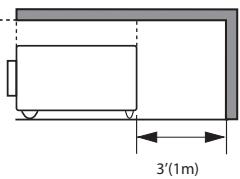
text_image
3'(1m)-If the projector is unused for an extended time, unplug the projector from the power outlet.
-Do not project the same image for a long time. The afterimage may remain on the LCD panels by the characteristic of panel.

CAUTION
DO NOT SET THE PROJECTOR IN GREASY, WET, OR SMOKY CONDITIONS SUCH AS IN A KITCHEN TO PREVENT A BREAKDOWN OR A DISASTER. IF THE PROJECTOR COMES IN CONTACT WITH OIL OR CHEMICALS, IT MAY BECOME DETERIORATED.

CAUTION
Not for use in a computer room as defined in the Standard for the Protection of Electronic Computer/Data Processing Equipment, ANSI/NFPA 75.
READ AND KEEP THIS USER GUIDE FOR LATER USE.
All the safety and operating instructions should be read before the product is operated.
Read all of the instructions given here and retain them for later use. Unplug this projector from AC power supply before cleaning. Do not use liquid or aerosol cleaners. Use a damp cloth for cleaning.
Follow all warnings and instructions marked on the projector.
For added protection to the projector during a lightning storm, or when it is left unattended and unused for long periods of time, unplug it from the wall outlet. This will prevent damage due to lightning and power line surges.
Do not expose this unit to rain or use near water... for example, in a wet basement, near a swimming pool, etc...
Do not use attachments not recommended by the manufacturer as they may cause hazards.
Do not place this projector on an unstable cart, stand, or table. The projector may fall, causing serious injury to a child or adult, and serious damage to the projector. Use only with a cart or stand recommended by the manufacturer, or sold with the projector. Wall or shelf mounting should follow the manufacturer's instructions, and should use a mounting kit approved by the manufacturers.
An appliance and cart combination should be moved with care. Quick stops, excessive force, and uneven surfaces may cause the appliance and cart combination to overturn.

natural_image
Silhouette of a person climbing a ladder inside a circular frame (no text or symbols)Slots and openings in the back and bottom of the cabinet are provided for ventilation, to ensure reliable operation of the equipment and to protect it from overheating.
The openings should never be covered with cloth or other materials, and the bottom opening should not be blocked by placing the projector on a bed, sofa, rug, or other similar surface. This projector should never be placed near or over a radiator or heat register.
This projector should not be placed in a built-in installation such as a book case unless proper ventilation is provided.
Never push objects of any kind into this projector through cabinet slots as they may touch dangerous voltage points or short out parts that could result in a fire or electric shock. Never spill liquid of any kind on the projector.
Do not install the projector near the ventilation duct of air-conditioning equipment.
This projector should be operated only from the type of power source indicated on the marking label. If you are not sure of the type of power supplied, consult your authorized dealer or local power company.
Do not overload wall outlets and extension cords as this can result in fire or electric shock. Do not allow anything to rest on the power cord. Do not locate this projector where the cord may be damaged by persons walking on it.
Do not attempt to service this projector yourself as opening or removing Covers may expose you to dangerous voltage or other hazards. Refer all servicing to qualified service personnel.
Unplug this projector from wall outlet and refer servicing to qualified service personnel under the following conditions:
a. When the power cord or plug is damaged or frayed.
b. If liquid has been spilled into the projector.
c. If the projector has been exposed to rain or water.
d. If the projector does not operate normally by following the operating instructions. Adjust only those controls that are covered by the operating instructions as improper adjustment of other controls may result in damage and will often require extensive work by a qualified technician to restore the projector to normal operation.
e. If the projector has been dropped or the cabinet has been damaged.
f. When the projector exhibits a distinct change in performance-this indicates a need for service.
When replacement parts are required, be sure the service technician has used replacement parts specified by the manufacturer that have the same characteristics as the original part. Unauthorized substitutions may result in fire, electric shock, or injury to persons.
Upon completion of any service or repairs to this projector, ask the service technician to perform routine safety checks to determine that the projector is in safe operating condition.
Air Circulation
Openings in the cabinet are provided for ventilation. To ensure reliable operation of the product and to protect it from overheating, these openings must not be blocked or covered.

CAUTION
Hot air is exhausted from the exhaust vent. When using or installing the projector, the following precautions should be taken.
- Do not put any flammable object or spray can near the projector, hot air is exhausted from the air vents.
- Keep the exhaust vent at least 3' (1m) away from any objects.
- Do not touch a peripheral part of the exhaust vent, especially screws and metallic parts. These areas will become hot while the projector is being used.
- Do not put anything on the cabinet. Objects put on the cabinet will not only get damaged but also may cause fire hazard by heat.
Cooling fans are provided to cool down the projector. The fans' running speed is changed according to the temperature inside the projector.
Installing the Projector in Proper Position
Install the projector properly. Improper installation may reduce the lamp life and cause a fire hazard.
Do not roll the projector more than 20 degrees from side to side.
Do not pitch the projector more than 30 degrees from above and below.

Do not point the projector up to project an image.

Do not point the projector down to project an image.

Do not put the projector on either side to project an image.
Moving the Projector
When moving the projector, replace the lens cap and retract adjustable foot to prevent damage to the lens and cabinet.
When the projector is not in use for an extended period, put it into a suitable case.

CAUTION IN CARRYING OR TRANSPORTING THE PROJECTOR
- Do not drop or bump the projector, otherwise damages or malfunctions may result.
- When carrying the projector, use a suitable carrying case.
- Do not transport the projector by courier or any other transport service in an unsuitable transport case. This may cause damage to the projector. For information about transporting the projector by courier or any other transport service, consult your dealer.
- Do not put the projector in a case before the projector is cooled enough.
AC Power Cord Requirement
The AC Power Cord supplied with this projector meets the requirement for use in the country you purchased it.
AC Power Cord for the United States and Canada:
AC Power Cord used in the United States and Canada is listed by the Underwriters Laboratories (UL) and certified by the Canadian Standard Association (CSA).
AC Power Cord has a grounding-type AC line plug. This is a safety feature to be sure that the plug will fit into the power outlet. Do not try to defeat this safety feature. Should you be unable to insert the plug into the outlet, contact your electrician.

AC Power Cord for the United Kingdom:
This cord is already fitted with a moulded plug incorporating a fuse, the value of which is indicated on the pin face of the plug. Should the fuse need to be replaced, an ASTA approved BS 1362 fuse must be used of the same rating, marked thus ◆. If the fuse cover is detachable, never use the plug with the cover omitted. If a replacement fuse cover is required, ensure it is of the same colour as that visible on the pin face of the plug (i.e. red or orange). Fuse covers are available from the Parts Department indicated in your User Instructions. If the plug supplied is not suitable for your socket outlet, it should be cut off and destroyed.
The end of the flexible cord should be suitably prepared and the correct plug fitted.
WARNING : A PLUG WITH BARED FLEXIBLE CORD IS HAZARDOUS IF ENGAGED IN A LIVE SOCKET OUTLET.
The Wires in this mains lead are coloured in accordance with the following code:
Green-and-yellow Earth
Blue....Neutral
Brown ..... Live
As the colours of the wires in the mains lead of this apparatus may not correspond with the coloured markings identifying the terminals in your plug proceed as follows:
The wire which is coloured green-and-yellow must be connected to the terminal in the plug which is marked by the letter E or by the safety earth symbol 12 or coloured green or green-and-yellow.
The wire which is coloured blue must be connected to the terminal which is marked with the letter N or coloured black.
The wire which is coloured brown must be connected to the terminal which is marked with the letter L or coloured red.
WARNING: THIS APPARATUS MUST BE EARTHED.
THE SOCKET-OUTLET SHOULD BE INSTALLED NEAR THE EQUIPMENT AND EASILY ACCESSIBLE.
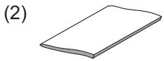
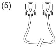
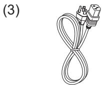
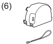
Contents of package
Your projector should come with the items shown below. Check that all the items are included.
Require of your dealer immediately if any items are missing.
(1) User Guide (CD-ROM x 1)
(2) Quick Start Guide (Book x 1)
(3) AC Power Cord
(4) Remote Control and Batteries
(5) VGA Cable
(6) Lens Cap with String
(7) PIN Code Label
(8) Ferrite core
text_image
(4) AUTO-RESET COMPUTER 1/6 10.0 GB 5000000000000000000000000000000000000000000000000000000000000000000000000000000 ViewSonic

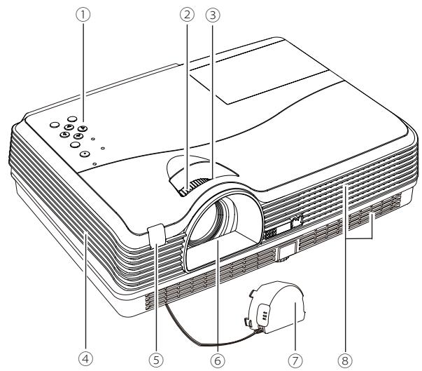
Front
text_image
Diagram of an projector with numbered parts labeled for identification① Top controls and Indicators
② Zoom Ring
③ Focus Ring
④ Speaker
⑤ Infrared Remote Receiver
⑥ Projection Lens
⑦ Lens Cap
(See page 61 for attaching.)

CAUTION
Do not turn on a projector with lens cap attached. High temperature from light beam may damage lens cap and result in fire hazard.
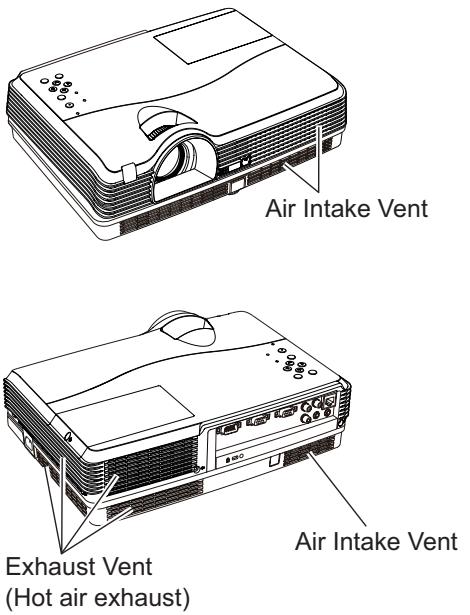
⑧ Air Intake Vent
Back
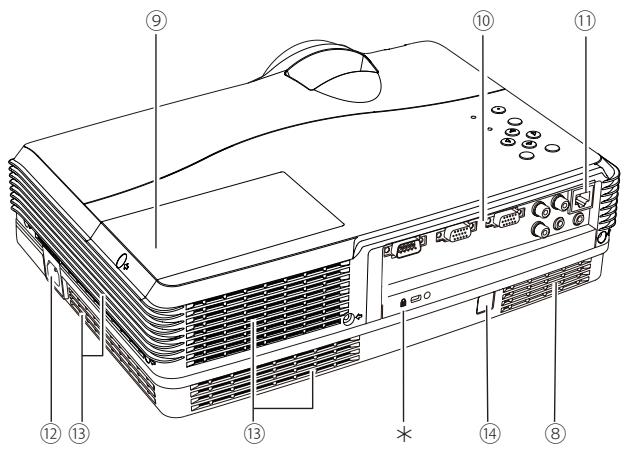
text_image
Diagram of an projector with numbered labels pointing to different components⑨ Lamp Cover
⑩ Terminals and Connectors
⑪ LAN Connection Terminal
⑫ Power Cord Connector
√Note:
Replace only with the same types of the supplied cords or cables. Using improper cords or cables may cause an electric shock or a fire.
⑬ Exhaust Vents

CAUTION
Hot air is exhausted from the exhaust vent. Do not put heat-sensitive objects near this side.
Bottom
text_image
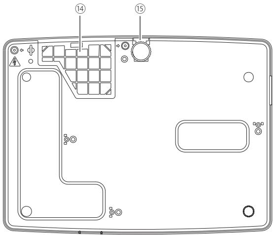
Technical diagram of a device rear panel with labeled components and numbered parts⑭ Filters
⑮ Adjustable Foot
√Note:
⑪ LAN Connection Terminal is for the Network function. Refer to the User Guide of “Network Set-up and Operation”.
*Kensington Security Slot
This slot is for a Kensington lock used to deter theft of the projector.
*Kensington is a registered trademark of ACCO Brands Corporation.
Rear Terminal
text_image
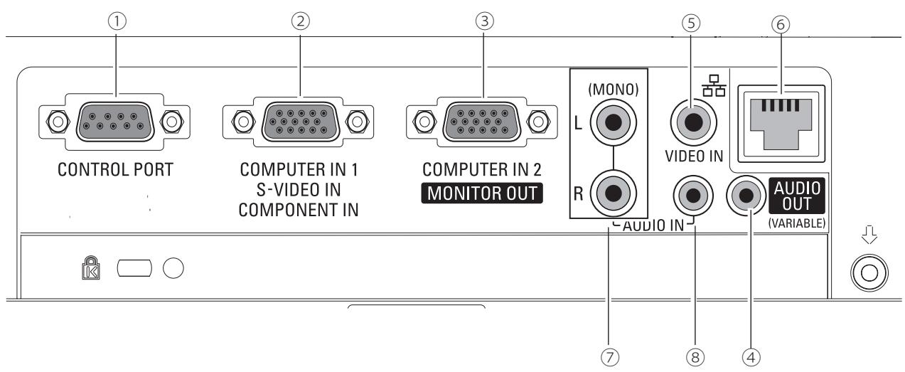
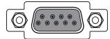
CONTROL PORT COMPUTER IN 1 S-VIDEO IN COMPONENT IN COMPUTER IN 2 MONITOR OUT (MONO) L R AUDIO IN VIDEO IN AUDIO OUT (VARIABLE)① CONTROL PORT
When the projector is controlled by a computer, connect to this jack with serial control cable.
② COMPUTER IN 1 /S-VIDEO IN / COMPONENT IN
Connect output signal from a computer, component video output, RGB scart 21-pin video output or S-video output to this terminal. (pp.14-16).
③ COMPUTER IN 2 / MONITOR OUT
- Connect analog RGB output signal from a computer to this terminal (p.14).
- This terminal can be used to output the incoming analog RGB and Component signal from COMPUTER IN 1 /S-VIDEO IN /COMPONENT IN terminal to the other monitor (pp.14,16).
Connect an external audio amplifier to this jack (pp.14-16).
This terminal outputs sound from AUDIO IN terminal.
Never plug headphones into this jack.
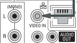
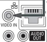
⑤ VIDEO IN
Connect the composite video output signal to this jack (p.15).
⑥ LAN Connection Terminal
Connect the LAN cable (refer to the User Guide of "Network Set-up and Operation").
⑦ AUDIO IN (Video)
Connect the audio output signal from video equipment connected to ⑤ to this jack. For a mono audio signal (a single audio jack), connect it to L(MONO) jack. (pp.14-16).
⑧ AUDIO IN (PC)
Connect the audio output signal from computer or video equipment connected to ② and ③ to this jack. (pp.14-16).
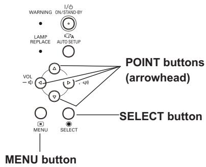
Top Control
text_image
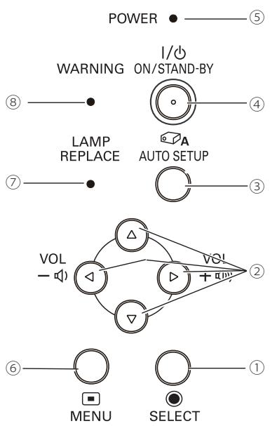
POWER WARNING I/O ON/STAND-BY LAMP REPLACE AUTO SETUP VOL - + - VOL - - MENU SELECT ⑤ ④ ③ ② ①① SELECT button
- Execute the selected item (p.21).
- Expand or compress the image in the Digital zoom mode (p.35).
② POINT ▲▼◀▶ (VOLUME -/+ ) buttons
-Select an item or adjust the value in the On-Screen Menu (p.21).
–Pan the image in the Digital zoom +/- mode (p.35).
-Adjust the volume level (Point ◀▶ buttons) (p.24).
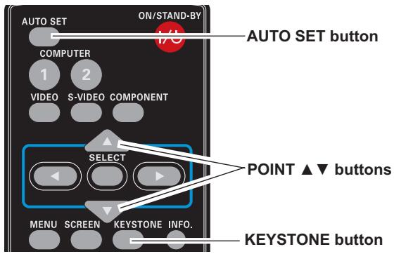
③ AUTO SETUP button
Execute the setting of Auto setup (includes Input search, Auto PC adj. and Auto Keystone functions) in the setting menu. (pp.23, 44).
④ ON/STAND-BY button
Turn the projector on or off (pp.18-20).
⑤ POWER indicator
—Lights red when the projector is in stand-by mode.
–Lights green during operations.
-Blinks green in the Power management mode (p.50).
⑥ MENU button
Open or close the On-Screen Menu (p.21).
⑦ LAMP REPLACE indicator
Lights yellow when the projection lamp reaches its end of life (pp.62, 69).
⑧ WARNING indicator
—Lights red when the projector detects an abnormal condition.
-Blinks red when the internal temperature of the projector exceeds the operating range (pp.59, 69).
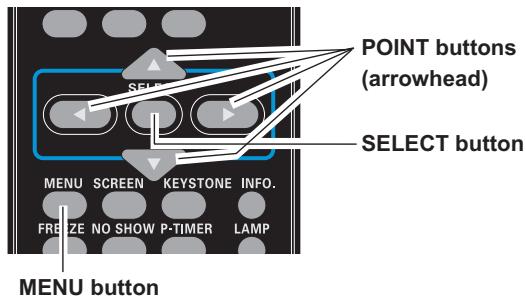
Remote Control
text_image
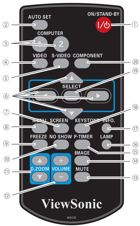
AUTO SET ON/STAND-BY COMPUTER VIDEO S-VIDEO COMPONENT SELECT MENU SCREEN KEYSTONE INFO. FREEZE NO SHOW P-TIMER LAMP IMAGE D.ZOOM VOLUME MUTE ViewSonic MXCS① ON/STAND-BY button
Turn the projector on or off. (pp.18-20)
② AUTO SET button
Execute the setting of Auto setup (includes Input search, Auto PC adj. and Auto Keystone functions) in the setting menu. (pp.23, 44)
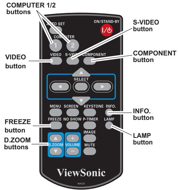
③ COMPUTER 1/2 buttons
Select the COMPUTER 1 or COMPUTER 2 input source. (pp.27, 37)
④ VIDEO button
Select the VIDEO input source. (p.36)
⑤ S-VIDEO button
Select the S-VIDEO input source. (p.36)
⑥ Point ▲▼◀▶ buttons
- Select an item or adjust the value in the On-Screen Menu. (p.21) - Pan the image in the Digital zoom +/- mode. (p.35)
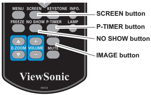
⑦ SCREEN button
Select a screen mode. (pp.26, 34-35, 42)
⑧ MENU button
Open or close the On-Screen Menu. (p.21)
⑨ FREEZE button
Freeze the picture on the screen. (p.25)
⑩ NO SHOW button
Temporarily turn off the image on the screen. (p.26)
⑪ D.ZOOM ▲▼ buttons
Zoom in and out the images. (pp.25, 35)
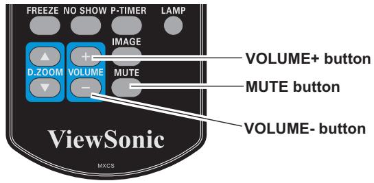
⑫ VOLUME +/- buttons
Adjust the volume level. (p.24)
⑬ MUTE button
Mute the sound. (p.24)
⑭ IMAGE button
Select the image mode. (pp.26, 32, 39)
⑮ P-TIMER button
Operate the P-timer function. (pp.26, 51)
⑯ LAMP button
Select a lamp mode. (pp.25, 53)
⑰ INFO. button
Operate the information function. (p.58)
⑱ KEYSTONE button
Correct keystone distortion. (pp.23, 45)
⑲ SELECT button
- Execute the selected item. (p.21) - Expand or compress the image in Digital zoom mode. (p.35)
⑳ COMPONENT button
Select the COMPONENT input source. (p.37)
√Note:
To ensure safe operation, please observe the following precautions:
- Do not bend, drop or expose the remote control to moisture or heat.
- For cleaning, use a soft dry cloth. Do not apply benzene, thinner, spray, or any chemical material.
Remote Control Battery Installation
1 Open the battery compartment lid.
2 Install new batteries into the compartment.
3 Replace the compartment lid.
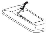

Two AAA size batteries
For correct polarity
(+ and -), be sure
battery terminals are
in contact with pins in
compartment.


To ensure safe operation, please observe the following precautions :
- Use two (2) AAA or LR03 type alkaline batteries.
• Always replace batteries in sets. - Do not use a new battery with a used battery.
- Avoid contact with water or liquid.
- Do not expose the remote control to moisture or heat.
- Do not drop the remote control.
- If the battery has leaked on the remote control, carefully wipe the case clean and install new batteries.
- Risk of an explosion if battery is replaced by an incorrect type.
- Dispose of used batteries according to the instructions or your local disposal rule or guidelines.
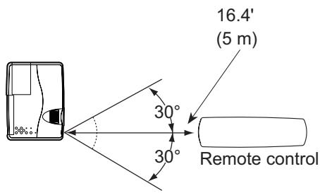
Remote Control Operating Range
Point the remote control toward the projector (Infrared Remote Receiver) when pressing the buttons. Maximum operating range for the remote control is about 16.4'(5 m) and 60 degrees in front of the projector.
text_image
16.4' (5 m) 30° 30° Remote controlRemote Control Code
The 2 different remote control codes (Code 1–Code 2) are assigned to this projector. Switching the remote control codes prevents interference from other remote controls when several projectors or video equipment next to each other are operated at the same time. Change the remote control code for the projector first before changing that for the remote control. See "Remote control" in the Setting Menu on page 53.
Press and hold the MENU and IMAGE buttons for more than five seconds to switch between the Code 1 and Code 2. The initial code is set to Code 1.
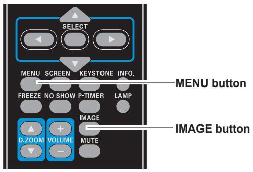
text_image
SELECT MENU SCREEN KEYSTONE INFO. FREEZE NO SHOW P-TIMER LAMP D.ZOOM VOLUME MUTE MENU button IMAGE buttonAdjustable Foot
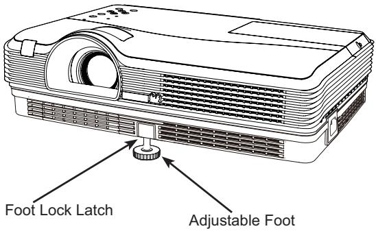
Projection angle can be adjusted up to 10.0 degrees with the adjustable foot.
Lift the front of the projector and push the foot lock latch on the projector.
Release the foot lock latch to lock the adjustable foot and rotate the adjustable foot to adjust the position and tilt.
To retract the adjustable foot, lift the front of the projector and push and undo the foot lock latch.
Keystone distortion of the projected image can be corrected by menu operation.(see pages 23, 44-45)
text_image
Foot Lock Latch Adjustable FootSetting up
Install the projector according to the environment and manner the projector will be used in.
For the case of installation in a special state such as ceiling mount, the specified mounting accessories and service may be required. Before installing the projector, consult your dealer about your installation.
Arrangement
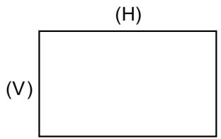
Refer to the following tables T-1 to determine the screen size and projection distance. The values shown in the table are calculated for a full size screen.
(H) x (V) : Screen size
(a) : Projection distance (from the projector's end)
(b), (c): Screen height
text_image
(H) (V)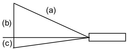
text_image
(a) (b) (c)T-1
(1024X768) (±10%)
| Screen Type | Screen size | Projection distance | Screen height | |||||||
| 4:3 | (H) | (V) | (a) min. | (a) max | (b) | (c) | ||||
| inch | m | m | m | inch | m | inch | cm | inch | cm | inch |
| 40 | 0.8 | 0.6 | 1.3 | 51 | 1.6 | 61 | 52 | 20 | -9 | -4 |
| 50 | 1.0 | 0.8 | 1.6 | 64 | 1.9 | 77 | 65 | 26 | -11 | -4 |
| 60 | 1.2 | 0.9 | 1.9 | 77 | 2.3 | 92 | 78 | 31 | -13 | -5 |
| 70 | 1.4 | 1.1 | 2.3 | 89 | 2.7 | 108 | 91 | 36 | -15 | -6 |
| 80 | 1.6 | 1.2 | 2.6 | 102 | 3.1 | 123 | 105 | 41 | -17 | -7 |
| 90 | 1.8 | 1.4 | 2.9 | 115 | 3.5 | 139 | 118 | 46 | -20 | -8 |
| 100 | 2.0 | 1.5 | 3.3 | 128 | 3.9 | 154 | 131 | 52 | -22 | -9 |
| 120 | 2.4 | 1.8 | 3.9 | 154 | 4.7 | 186 | 157 | 62 | -26 | -10 |
| 150 | 3.0 | 2.3 | 4.9 | 193 | 5.9 | 232 | 196 | 77 | -33 | -13 |
| 200 | 4.1 | 3.0 | 6.5 | 258 | 7.9 | 310 | 261 | 103 | -44 | -17 |
| 250 | 5.1 | 3.8 | 8.2 | 323 | 9.8 | 388 | 327 | 129 | -54 | -21 |
| 300 | 6.1 | 4.6 | 9.8 | 387 | 11.8 | 466 | 392 | 154 | -65 | -26 |
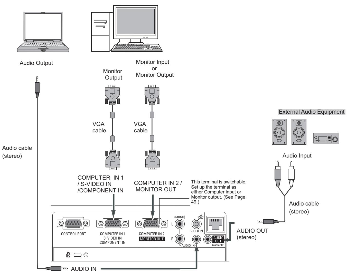
Connecting to a Computer
Cables used for connection
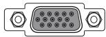
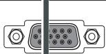
- VGA Cables (Mini D-sub 15 pin) *(Only one cable is supplied.)
- Audio Cables
(*One cable is supplied; other cables are not supplied with the projector.)
flowchart
graph TD
    A["Audio Output"] --> B["Monitor Output"]
    B --> C["VGA cable"]
    C --> D["COMPUTER IN 1 / S-VIDEO IN /COMPONENT IN"]
    D --> E["CONTROL PORT"]
    D --> F["COMPUTER IN 1 S-VIDEO IN COMPONENT IN"]
    F --> G["COMPUTER IN 2 MONITOR OUT"]
    G --> H["L (MONO)"]
    G --> I["R (R)"]
    H --> J["VIDEO IN"]
    I --> K["AUDIO OUT (VARIABLE)"]
    L["External Audio Equipment"] --> M["Audio Input"]
    M --> N["Audio cable (stereo)"]
    O["Audio IN"] --> P["Audio OUT (stereo)"]
√Note:
- Input sound to the AUDIO IN terminal when using the COMPUTER IN 1/ S-VIDEO IN / COMPONENT IN and the COMPUTER IN 2/MONITOR OUT terminals as input.
- When the AUDIO OUT is plugged-in, the projector's built-in speaker is not available.
- When the cable is of the longer variety, it is advisable to use the COMPUTER IN 1 /S-VIDEO IN /COMPONENT IN and not the COMPUTER IN 2/MONITOR OUT.

Unplug the power cords of both the projector and external equipment from the AC outlet before connecting cables.
Connecting to Video Equipment
Cables used for connection
- Video Cable
- S-Video Cable
• S-Video-VGA Cable - Audio Cables
(Cables are not supplied with the projector.)
S-Video Output and Audio output
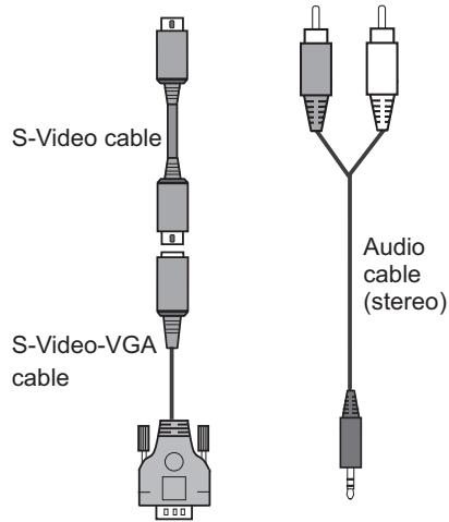
text_image
S-Video cable S-Video-VGA cable Audio cable (stereo)COMPUTER IN 1
/ S-VIDEO IN
/COMPONENT IN

Composite Video and Audio Output
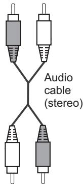
text_image
Audio cable (stereo)AUDIO IN
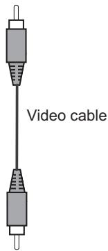
text_image
Video cableVIDEO IN
External Audio Equipment


Audio Input
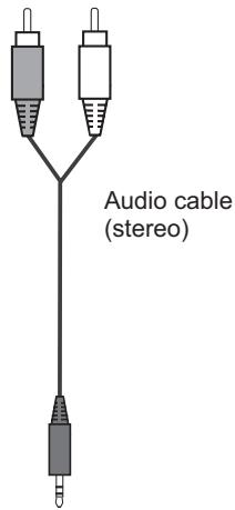
text_image
Audio cable (stereo)AUDIO OUT (stereo)
CONTROL PORT
COMPUTER IN 1
S-VIDEO IN
COMPONENT IN
COMPUTER IN 2
MONTOR OUT
AUDIO IN-
(VARIABLE)
√Note:
When the AUDIO OUT is plugged-in, the projector's built-in speaker is not available.

Unplug the power cords of both the projector and external equipment from the AC outlet before connecting cables.
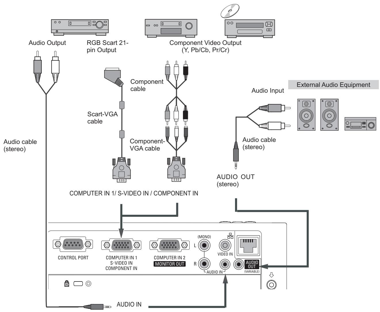
Connecting to Component Video and RGB (Scart) Equipment
Cables used for connection
- Audio Cables
- Scart-VGA Cable
- Component Cable
- Component-VGA Cable
(Cables are not supplied with this projector.)
flowchart
graph TD
    A["Audio Output"] --> B["RGB Scart 21-pin Output"]
    B --> C["Scart-VGA cable"]
    C --> D["Component cable"]
    D --> E["Component-VGA cable"]
    E --> F["Computer in 1/ S-VIDEO IN / COMPONENT IN"]
    F --> G["CONTROL PORT"]
    F --> H["COMPUTER IN 1 S-VIDEO IN COMPONENT IN"]
    F --> I["COMPUTER IN 2 MONITOR OUT"]
    I --> J["(MONO) L R"]
    J --> K["VIDEO IN"]
    K --> L["AUDIO OUT (VARIABLE)"]
    L --> M["Audio IN"]
    N["Component Video Output (Y, Pb/Cb, Pr/Cr)"] --> O["Audio Input"]
    O --> P["Audio cable (stereo)"]
    Q["External Audio Equipment"] --> R["Audio OUT (stereo)"]
√Note:
When the AUDIO OUT is plugged-in, the projector's built-in speaker is not available.

Unplug the power cords of both the projector and external equipment from the AC outlet before connecting cables.
Using the Ferrite Core
Before using the AC Power Cord, attach the ferrite core (supplied) as shown below. (See below for mounting location.)
The Power Cord with ferrite core must be used for RF interference suppression.
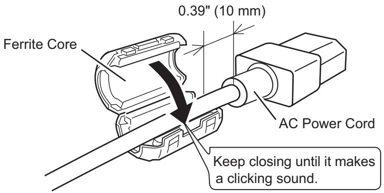
text_image
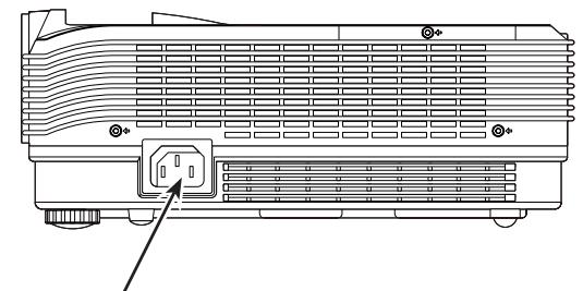
Ferrite Core 0.39" (10 mm) AC Power Cord Keep closing until it makes a clicking sound.Connecting the AC Power Cord
This projector uses nominal input voltages of 100-240 V AC and it automatically selects the correct input voltage. It is designed to work with single-phase power systems having a grounded neutral conductor. To reduce the risk of electrical shock, do not plug into any other type of power system.
If you are not sure of the type of power being supplied, consult your authorized dealer or service center.
Connect the projector with all peripheral equipment before turning the projector on.
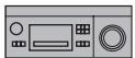
natural_image
Line drawing of a projector unit with a power connector (no text or symbols)Connect the AC power cord (supplied) to the projector.

CAUTION
The AC outlet must be near this equipment and must be easily accessible.
√Note:
Unplug the AC power cord when the projector is not in use. When this projector is connected to an outlet with the AC power cord, it is in Stand-by mode and consumes a little electric power.
| NOTE ON THE POWER CORDAC power cord must meet requirement of the country where you use the projector.Confirm the AC plug type with the chart below and proper AC power cord must be used.If supplied AC power cord does not match your AC outlet, contact your sales dealer. | |||
| Projector side | AC outlet side | ||
 To power cordconnector on yourprojector. To power cordconnector on yourprojector. | For the U.S.A. and Canada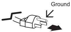 To the AC outlet.(120 V AC) To the AC outlet.(120 V AC) | For Continental Europe To the AC outlet.(200 - 240 V AC) To the AC outlet.(200 - 240 V AC) | For the U.K. To the AC outlet.(200 - 240 V AC) To the AC outlet.(200 - 240 V AC) |
Turning On the Projector
1 Complete peripheral connections (with a computer, VCR, etc.) before turning on the projector.
2 Connect the projector's AC power cord into an AC outlet. The POWER indicator lights red. Open the lens cap (see pages 8, 61).
3 Press the ON/STAND-BY button on the top control or on the remote control. The POWER indicator lights green and the cooling fans start to operate. The preparation display appears on the screen.
4 After about 3 seconds, the input source that was selected the last time and the lamp control status icon (see page 53) appear on the screen.
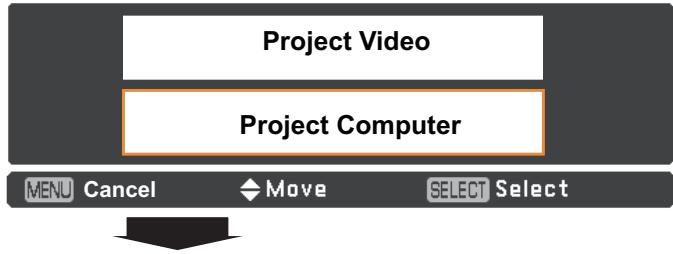
5 If there is no signal input when start on the projector, or the current signal is missed while operating the projector, the Video/PC selection window will be displayed on the screen, please move the pointer to input source desired by pressing the Point ▲▼ buttons and press the SELECT button. And then follow the input signal guidance window to correct the signal and connection.
If the projector is locked with a PIN code, PIN code input dialog box will appear. Enter the PIN code as instructed on the next page.
√Note:
- When the Logo select function is set to Off, the logo will not be shown on the screen (p.46).
- When Off is selected in the Display function, the preparation display will not be shown on the screen (p.45).
- When the Input Search function is set to On2, the input signal will be searched automatically (p.44).
- When Off is selected in the Display function, the Video/PC selection window and the input signal guidance window are not shown on the screen. (p.45)
ViewSonic®
The preparation display will disappear after 3 seconds.
Selected Input Source and Lamp Control

Lamp control status
(See page 53 for Lamp control status.)
√Note:
The Filter warning and Lamp replacement icons may appear on the screen depending on the usage state of the projector.
Video / PC selection window
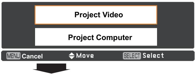
flowchart
graph TD
    A["Project Video"] --> B["Project Computer"]
    B --> C["MENU Cancel"]
    B --> D["Move"]
    B --> E["SELECT Select"]
Input signal guidance window
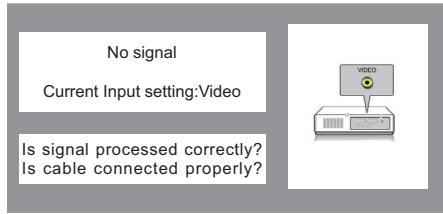
text_image
No signal Current Input setting:Video Is signal processed correctly? Is cable connected properly?Video / PC selection window
flowchart
graph TD
    A["Project Video"] --> B["Project Computer"]
    B --> C["MENU Cancel"]
    B --> D["Move"]
    B --> E["SELECT Select"]
Input signal guidance window
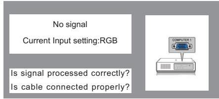
text_image
No signal Current Input setting:RGB Is signal processed correctly? Is cable connected properly?Enter a PIN code
Use the Point ▲▼ buttons to enter a number. Press the Point ◀▶ buttons to fix the number and move the red frame pointer to the next box. The number changes to “*”. If you fixed an incorrect number, use the Point ◀▶ buttons to move the pointer to the number you want to correct, and then enter the correct number.
Repeat this step to complete entering a four-digit number.
After entering the four-digit number, move the pointer to Set. Press the SELECT button so that you can start to operate the projector.
If you entered an incorrect PIN code, PIN code and the number (****) will turn red for a moment. Enter the correct PIN code all over again.
What is PIN code?
PIN (Personal Identification Number) code is a security code that allows the person who knows it to operate the projector. Setting a PIN code prevents unauthorized use of the projector.
A PIN code consists of a four-digit number. Refer to the PIN code lock function in the Setting Menu on pages 54-55 for locking operation of the projector with your PIN code.
√Note:
- If the PIN code number is not entered or wrong PIN code number is entered within three minutes after the PIN code dialog box appeared, the projector will be turned off automatically.
- The “1234” is set as the initial PIN code at the factory.
- If you forget your PIN code, the projector can no longer be started.
PIN Code Input Dialog Box
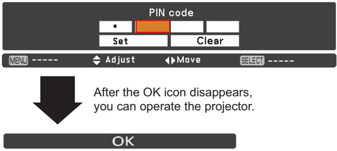
text_image
PIN code * Set Clear MENU ---- Adjust Move SELECT ---- After the OK icon disappears, you can operate the projector. OKTurning Off the Projector
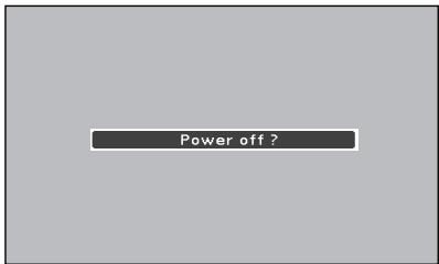
1 Press the ON/STAND-BY button on the top control or on the remote control, and Power off? appears on the screen.
2 Press the ON/STAND-BY button again to turn off the projector. The POWER indicator lights red and the cooling fans stop (default setting), and you can unplug the AC power cord.
If L1 is selected in Fan menu (p.56), the POWER indicator starts to blink red and the cooling fans keep running for about 60 seconds, then the POWER indicator lights red and the cooling fans stop. You can unplug the AC power cord even if the cooling fans are still running.

TO MAINTAIN THE LIFE OF THE LAMP, ONCE YOU TURN THE PROJECTOR ON, WAIT AT LEAST FIVE MINUTES BEFORE TURNING IT OFF.

DO NOT OPERATE THE PROJECTOR CONTINUOUSLY WITHOUT REST. CONTINUOUS USE MAY RESULT IN SHORTENING THE LAMP LIFE. TURN OFF THE PROJECTOR AND LET STAND FOR ABOUT AN HOUR IN EVERY 24 HOURS.
√Note:
- When the Direct on function is set to On, the projector will be turned on automatically by connecting the AC power cord to an AC outlet (p.50).
- The running speed of cooling fans is changed according to the temperature inside the projector.
- Do not put the projector in a case before the projector is cooled enough.
- If the WARNING indicator blinks or lights red, see "WARNING indicator" on page 59.
- While the POWER indicator is blinking, the lamp is being cooled down and the projector cannot be turned on. Wait until the POWER indicator stops blinking to turn on the projector again.
- The projector can be turned on after the POWER indicator lights red.
- When L2 is selected in Fan menu (p.56) and the projector is turned on right after it turns off, it takes a while to start projecting.
text_image
Power off ?Power off? disappears after 4 seconds.
Direct Off Function
You can disconnect the power cord from the wall outlet or turn off the breaker even during projection without pressing the on/stand-by button.
√Note:
When using the Direct Off function, you cannot restart the projector immediately after the power is disconnected. If the external power supply is suddenly cut off, the fans stop immediately. The lamp remains high temperature and needs to be cooled.
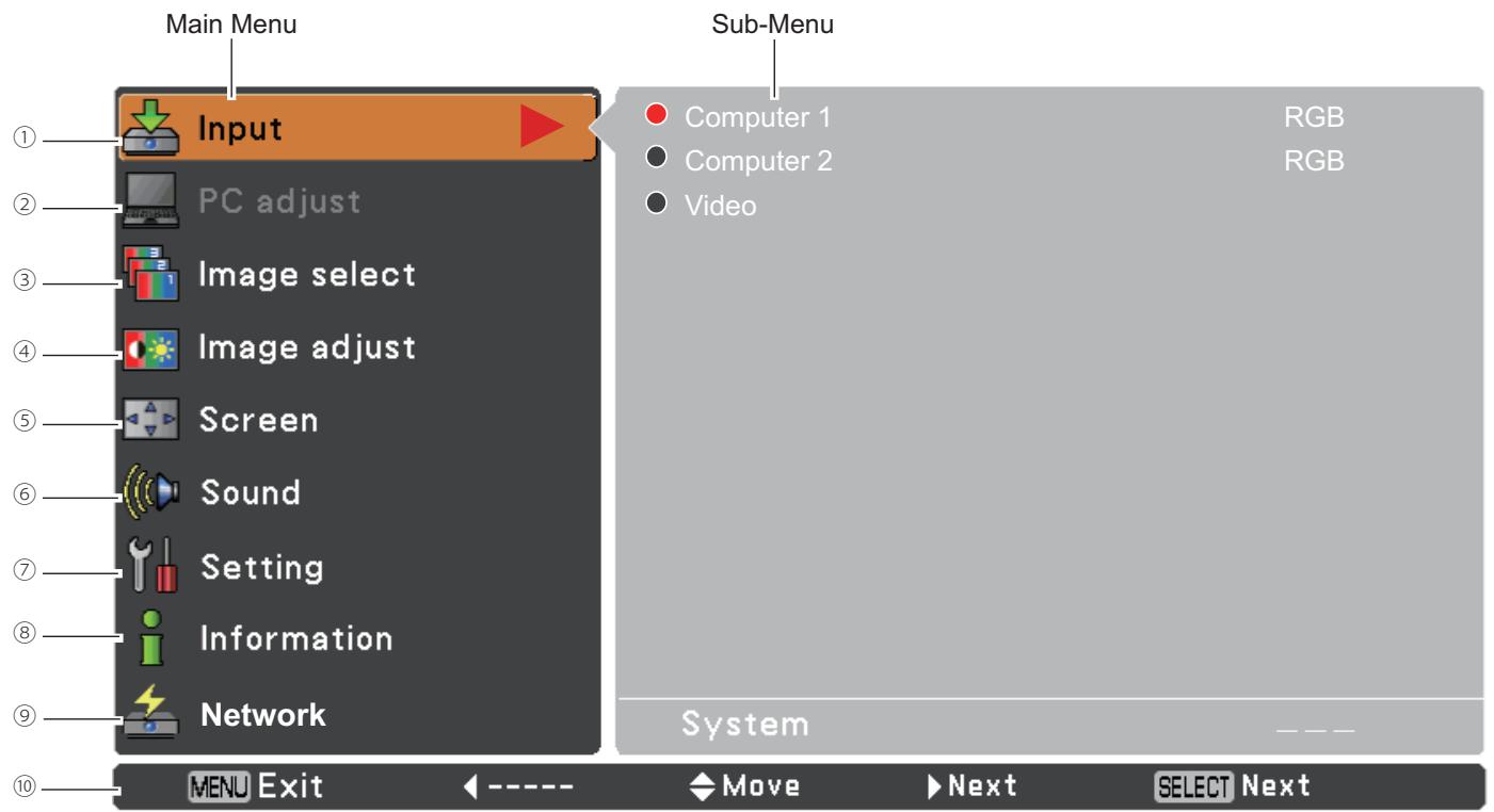
How to Operate the On-Screen Menu
The projector can be adjusted or set via the On-Screen Menu. The menus have a hierarchical structure, with a main menu that is divided into submenus, which are further divided into other submenus. For each adjustment and setting procedure, refer to respective sections in this manual.
1 Press the MENU button on the top control or the remote control to display the On-Screen Menu.
2 Use the Point ▲▼ buttons to highlight or select a main menu item. Press the Point ▶ or the SELECT button to access the submenu items. (The selected item is highlighted in orange.)
3 Use the Point ▲▼ buttons to select the desired submenu item and press the SELECT button to set or access the selected item.
4 Use the Point ▲▼◀▶ buttons to adjust the setting or switch between each option and press the SELECT button to activate it and return to the submenu.
5 Press the Point ◀ button to return to the main menu. Press the MENU button to exit the On-Screen Menu.
Top Control
flowchart
graph TD
    A["MENU button"] --> B["SELECT button"]
    B --> C["VOL"]
    C --> D["△"]
    C --> E["V"]
    D --> F["○"]
    E --> G["●"]
    F --> H["○"]
    G --> I["○"]
    H --> J["LAMP REPLACE"]
    I --> K["ON/STAND-BY"]
    J --> L["○"]
    K --> M["○"]
    L --> N["○"]
    M --> O["○"]
    N --> P["○"]
    O --> Q["○"]
    P --> R["○"]
    Q --> S["○"]
    R --> T["○"]
    S --> U["○"]
    T --> V["○"]
    U --> W["○"]
    V --> X["○"]
    W --> Y["○"]
    X --> Z["○"]
    Y --> AA["○"]
    Z --> AB["○"]
Remote Control
text_image
POINT buttons (arrowhead) SELECT button MENU SCREEN KEYSTONE INFO. FREZEN NO SHOW P-TIMER LAMP MENU buttonOn-Screen Menu
text_image
Input PC adjust Image select Image adjust Screen Sound Setting Information Network Dynamic Standard Real Blackboard(Green) Colorboard Image 1 Image 2 Image 3 Image 4 Red Menu Exit ← ---- → Move → Next → SELECT → Next Point or SELECT button The currently set item is check marked. The selected item is highlighted in orange. Input PC adjust Image select Image adjust Screen Sound Setting Information Network Dynamic Standard Real Blackboard(Green) Colorboard Image 1 Image 2 Image 3 Image 4 Red Menu Exit ← Back → Move → ---- → SELECT → SelectMenu Bar
For detailed functions of each menu, see "Menu Tree" on pages 67-68.
text_image
Main Menu Input PC adjust Image select Image adjust Screen Sound Setting Information Network Sub-Menu Computer 1 Computer 2 Video RGB RGB System MENU Exit Move Next SELECT Next① Input
Used to select an input source from Computer 1, Computer 2 or Video (pp.27, 36-37).
② PC adjust
Select Auto PC adj., Fine sync, Total dots, Horizontal, Vertical, Current mode, Clamp, Display area-H and Display area-V to adjust the parameters to match with the PC input signal format (pp.29-31).
③ Image select
For computer source, used to select an image mode from among Dynamic, Standard, Real, Blackboard(Green), Colorboard and image 1 - 4 (p.32).
For Video source, used to select an image mode among Dynamic, Standard, Cinema, Blackboard(Green), Colorboard and Image 1-4 (p.39).
④ Image adjust
For computer source, used to adjust computer image [Contrast, Brightness, Color temp., White balance (R/G/B), Sharpness and Gamma] (pp.33-34).
For Video source, used to adjust picture image [Contrast, Brightness, Color, Tint, Color temp., White balance (R/G/B), Sharpness, Gamma, Noise reduction and Progressive] (pp.40-41).
⑤ Screen
For computer source, used to adjust size of the image [ Normal, True, Wide, Full, Custom, Custom adj. and Digital zoom +/- ] (pp.34-35).
For Video source, used to set size of image [Normal, Wide, Custom and Custom adj.] (p.42).
⑥ Sound
Used to adjust the volume or mute the sound (p.24).
⑦ Setting
Used to set the projector's operating configurations (pp.43-57).
⑧ Information
Display the input source information: Input, H-sync freq., V-sync freq., Screen, Language, Lamp status, Lamp counter, Power management, Key lock, PIN code lock and Remote control (p.58).
⑨ Network
See the User Guide of "Network Set-up and Operation".
⑩ Guide
The key operation is displayed.
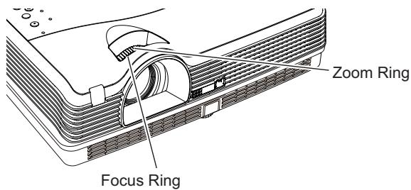
Zoom and Focus Adjustment
Rotate the Zoom Ring to zoom in and out. Rotate the Focus Ring to adjust the focus of the image.
text_image
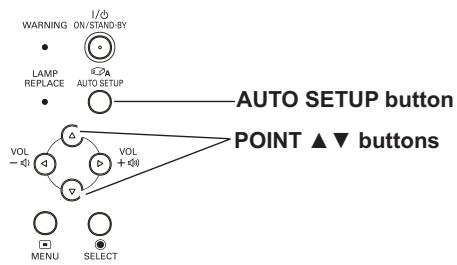
Zoom Ring Focus RingAuto Setup Function
Auto setup function is provided to automatically execute the setting of Auto setup (includes Input search, Auto PC adj. and Auto Keystone functions) in the setting menu by just pressing the AUTO SETUP button on the top control or the AUTO SET button on the remote control. Refer to page 44 for the setting of the Auto setup function.
√Notes:
- Auto Keystone corrects vertical distortion only; it does not correct horizontal distortion.
- Auto Keystone cannot work when Ceiling feature is set to On in the Setting menu (p.49).
- Perfect correction of the image distortion cannot be ensured with the Auto setup function. If the distortion cannot be corrected properly by pressing the AUTO SETUP or AUTO SET button, adjust manually by pressing the KEYSTONE button on the remote control or selecting Keystone in the Setting menu (p.45).
- Fine sync, Total dots, Horizontal and Vertical position of some computers cannot be fully adjusted with the Auto PC Adjustment function. When the image is not provided properly with this operation, manual adjustments are required (pp.30-31).
Top Control
flowchart
graph TD
    A["WARNING ON/STAND BY"] --> B["LAMP REPLACE"]
    B --> C["AUTO SETUP"]
    C --> D["POINT ▲▼ buttons"]
    D --> E["VOL -"]
    D --> F["VOL +"]
    E --> G["MENU SELECT"]
    F --> H["NOT"]
    style A fill:#f9f,stroke:#333
    style B fill:#ccf,stroke:#333
    style C fill:#cfc,stroke:#333
    style D fill:#fcc,stroke:#333
    style E fill:#ffc,stroke:#333
    style F fill:#cfc,stroke:#333
    style G fill:#fcc,stroke:#333
    style H fill:#cfc,stroke:#333
Remote Control
text_image
AUTO SET ON/STAND-BY COMPUTER 1 2 VIDEO S-VIDEO COMPONENT SELECT MENU SCREEN KEYSTONE INFO. AUTO SET button POINT ▲▼ buttons KEYSTONE buttonKeystone Correction
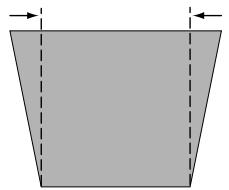
If a projected picture still has keystone distortion after pressing the AUTO SETUP button on the top control or the AUTO SET button on the remote control, correct the image manually as follows:
Press the KEYSTONE button on the remote control. The Keystone dialog box appears. Use the Point ▲▼ buttons to correct keystone distortion. The keystone adjustment can be stored (see page 45).
Reduce the upper width with the Point ▲ button.
Reduce the lower width with the Point ▼ button.
natural_image
Simple geometric diagram of a trapezoid with dashed vertical lines and arrows indicating width (no text or symbols)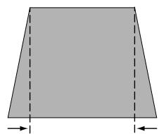
natural_image
Simple geometric diagram of a trapezoid with dashed vertical lines and arrows indicating width (no text or labels)Keystone

- The white arrows indicate that there is no correction.
- A red arrow indicates the direction of correction.
- An arrow disappears at the maximum correction.
- If you press the KEYSTONE button on the remote control once more while the keystone dialog box is being displayed, the keystone adjustment will be canceled.
- The adjustable range is limited depending on the input signal.
Sound Adjustment
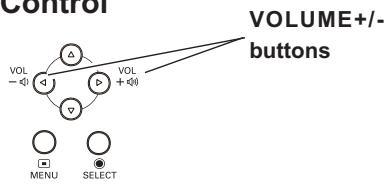
Direct Operation
Volume
Press the VOLUME+/- buttons on the top control or on the remote control to adjust the volume. The volume dialog box appears on the screen for a few seconds.
Mute
Press the MUTE button on the remote control to select On to temporarily turn off the sound. To turn the sound back on, press the MUTE button again to select Off or press the VOLUME +/- buttons. The Mute function is also effective for the AUDIO OUT jack.
Menu Operation
1 Press the MENU button to display the On-Screen Menu. Use the Point ▲▼ buttons to select Sound. Press the Point ▶ or the SELECT button to access the submenu items.
2 Use the Point ▲▼ buttons to select the desired submenu item and press the SELECT button to access the selected item.
Volume
Press the Point ▶ button to turn up the volume; press the Point ◀ button to turn down the volume.
Mute
Press the SELECT button to switch the mute function On/Off. When the sound is turned off, On is displayed. Press the VOLUME +/- buttons again to turn the sound back on.
Top Control
flowchart
graph TD
    A["VOLUME+/- buttons"] --> B["Directional Control"]
    B --> C["Menu"]
    B --> D["SELECT"]
    C --> E["Directional Control"]
    D --> F["Directional Control"]
Remote Control
text_image
FREEZE NO SHOW P-TIMER LAMP IMAGE D.ZOOM VOLUME MUTE VOLUME+ button MUTE button VOLUME- button ViewSonic MXCSVolume Dialog Box
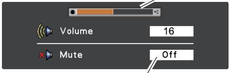
text_image
Volume 16 Mute OffPress the MUTE button to set the Mute function On or Off. The dialog box disappears after 4 seconds.
Sound Menu
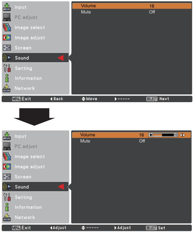
text_image
Input PC adjust Image select Image adjust Screen Sound Setting Information Network MENU Exit ← Back → Move → ---- SELECT Next Volume 16 Mute Off INPUT PC adjust Image select Image adjust Screen Sound Setting Information Network MENU Exit ← Adjust ← ---- ▶Adjust Select SetRemote Control Operation
Using the remote control for some frequently used operations is advisable. Just pressing one of the buttons enables you to make the desired operation quickly without calling up the On-Screen Menu.
COMPUTER 1/2, VIDEO, S-VIDEO and COMPONENT buttons
Press the COMPUTER 1/2, VIDEO, S-VIDEO and COMPONENT buttons on the remote control to select the input source. See pages 27, 36-37 for details.
FREEZE button
Press the FREEZE button on the remote control to freeze the picture on the screen, meanwhile, volume is muted. To cancel the Freeze function, press the FREEZE button again or press any other button.
Fig.1 will appear on the Screen menu while the Freeze function is working.
Fig.1

INFO. button
Display the input source information: Input, H-sync freq., V-sync freq., Screen, Language, Lamp status, Lamp counter, Power management, Keylock, PIN code lock and Remote control (p.58).
D.ZOOM buttons
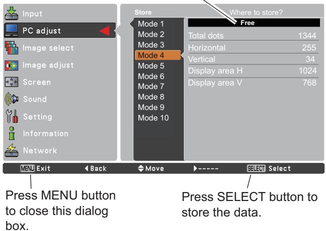
Press the D.ZOOM buttons on the remote control to enter to the Digital zoom +/- mode. See page 35 for details.
LAMP button
Press the LAMP button on the remote control to select the lamp mode for changing the brightness on the screen.
High...... Brighter than the Normal mode.
Normal..... Normal brightness
Eco .... Lower brightness reduces the lamp power consumption and extends the lamp life.
Remote Control
text_image
COMPUTER 1/2 buttons AUTO SET ON/STAND-BY S-VIDEO button VIDEO button S-VIDEO COMPONENT COMPONENT button SELECT MENU SCREEN KEYSTONE INFO. FREEZE NO SHOW P-TIMER LAMP INFO. button D.ZOOM VOLUME MUTE LAMP button D.ZOOM - ViewSonic MXCS√Note:
See the next page for the description of other buttons.
NO SHOW button
Press the NO SHOW button on the remote control to black out the image. To restore to normal, press the NO SHOW button again or press any other button. When the projected image is captured and is set as User in the Logo selection (p.47), the screen changes each time you press the NO SHOW button as follows.
black out → captured image → normal →……
√Note:
When use the MUTE button to release the No Show function, the mute function can not be operated at the same time.
P-TIMER button
Press the P-TIMER button on the remote control to operate the Count up/Count down function. Refer to p.51 for detail of Setting for the P-timer function.
To stop the count time, press the P-TIMER button.
To cancel the P-timer function, press and hold the P-TIMER button.
IMAGE button
Press the IMAGE button on the remote control to select a desired image mode of the screen. See pages 32, 39 for details.
SCREEN button
Select the screen size (See pages 34-35, 42 for details).

text_image
No showNo show disappears after 4 seconds.


P-Timer display
text_image
MENU SCREEN KEYSTONE INFO. FREEZE NO SHOW P-TIMER LAMP D.ZOOM VOLUME MUTE SCREEN button P-TIMER button NO SHOW button IMAGE button IMAGE button ViewSonic MXCS√Note:
See the previous page for the description of other buttons.
Input Source Selection (RGB: Computer 1/Computer 2)
Direct Operation
Choose either Computer 1(RGB) or Computer 2(RGB) by pressing the COMPUTER 1 or COMPUTER 2 button on the remote control.
Before using these buttons, correct input source should be selected through Menu operation as described below.
Remote Control
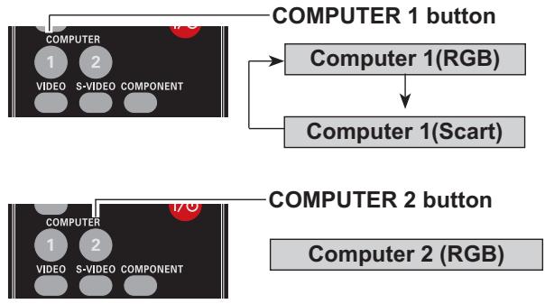
flowchart
graph TD
    A["COMPUTER 1 button"] --> B["Computer 1(RGB)"]
    B --> C["Computer 1(Scart)"]
    D["COMPUTER 2 button"] --> E["Computer 2 (RGB)"]
Menu Operation
1 Press the MENU button to display the On-Screen Menu. Use the Point ▲▼ buttons to select Input and then press the Point ▶ or the SELECT button.
2 Use the Point ▲▼ buttons to select Computer 1.
3 When Computer 1 is selected, press the Point ▶ button to access the submenu items. Use the Point ▲▼ buttons to select the RGB input source and then press the SELECT button.
√Note:
When the Input Search function is set to On1 or On2 in the Auto setup function, the input signal will be searched automatically (p.44).
Input Menu
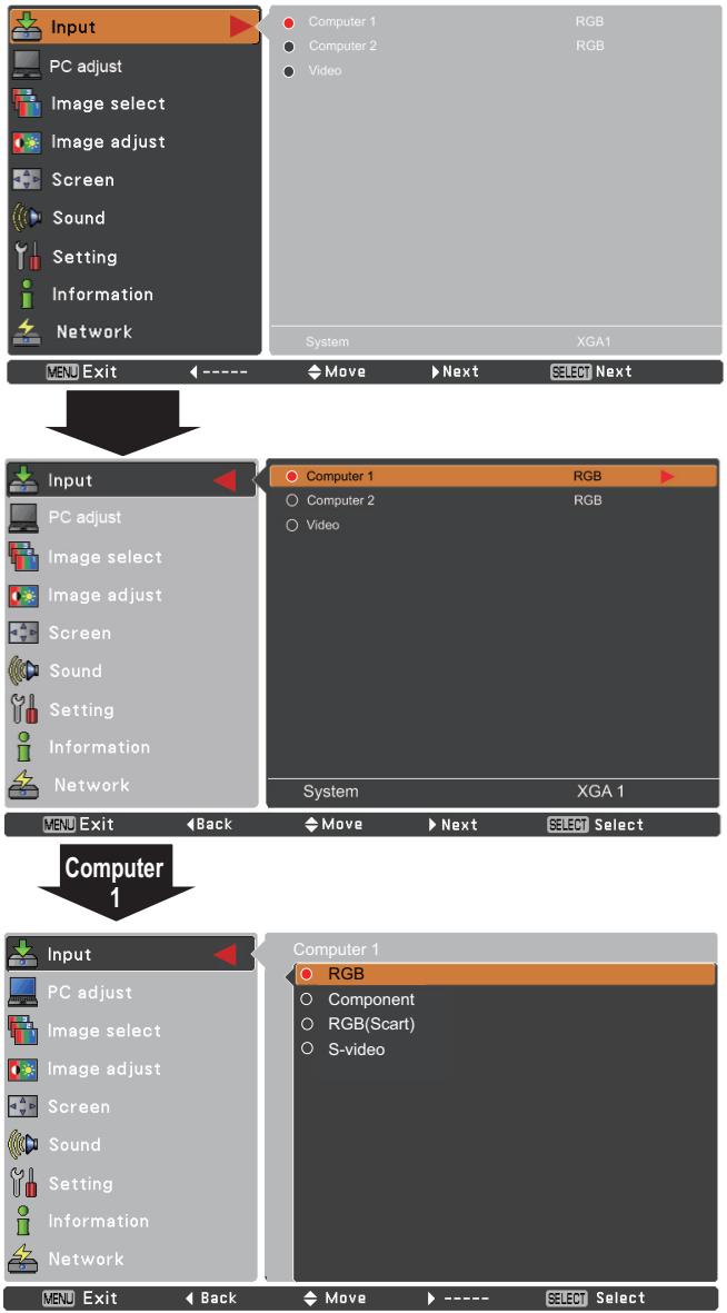
text_image
Input PC adjust Image select Image adjust Screen Sound Setting Information Network MEN Exit ----→Move→Next→SELECT Next Input PC adjust Image select Image adjust Screen Sound Setting Information Network MEN Exit Back Move→Next→SELECT Select Computer 1 Input PC adjust Image select Image adjust Screen Sound Setting Information Network MEN Exit Back Move→----→SELECT Select Computer 1 RGB Component RGB(Scart) S-videoComputer System Selection
This projector automatically tunes to various types of computers with its Multi-scan system and Auto PC Adjustment. If a computer is selected as a signal source, this projector automatically detects the signal format and tunes to project a proper image without any additional settings. (Signal formats provided in this projector are shown on page 70.)
One of the following messages may appear when:
Auto
When the projector cannot recognize the connected signal conforming to the provided PC systems, Auto is displayed on the System Menu box and the Auto PC Adjustment function works to display proper images. If the image is not projected properly, a manual adjustment is required (pp.30-31).
■■■■■
There is no signal input from the computer. Check the connection between your computer and the projector. (See “Troubleshooting” on p.64.)
Mode 1
The preset system is manually adjusted in the PC adjust Menu. The adjusted data can be stored in Mode 1–10 (pp.30-31).
SVGA 1
PC Systems provided in this projector is chosen. The projector chooses a proper system provided in the projector and displays it.
*Mode 1 and SVGA 1 are examples.
Selecting Computer System Manually
PC system can also be selected manually.
1 Press the MENU button to display the On-Screen Menu. Use the Point ▲▼ buttons to select Input and then press the Point ▶ or the SELECT button.
2 Use the Point ▲▼ buttons to select System and then press the Point ▶ or the SELECT button.
3 Use the Point ▲▼ buttons to select the desired system and then press the SELECT button.
PC System Menu
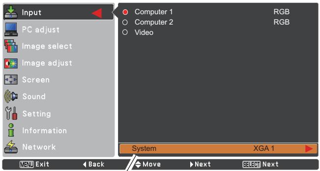
text_image
Input PC adjust Image select Image adjust Screen Sound Setting Information Network Computer 1 Computer 2 Video RGB RGB System XGA 1 XEN Exit Back Move Next Select NextThe PC System Menu Selected system is displayed.
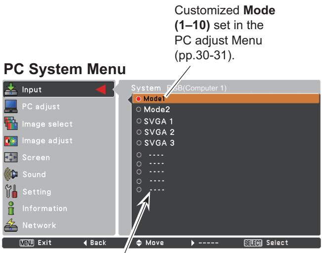
text_image
Customized Mode (1-10) set in the PC adjust Menu (pp.30-31). PC System Menu Input PC adjust Image select Image adjust Screen Sound Setting Information Network System RGB(Computer 1) Model1 Mode2 SVGA 1 SVGA 2 SVGA 3 .... .... .... .... ... Menu Exit Back Move ---- SELECT SelectSystems in this dialog box can be selected.
Auto PC Adjustment
Auto PC Adjustment function is provided to automatically adjust Fine sync, Total dots, Horizontal and Vertical positions to conform to your computer.
Menu Operation
Auto PC adj.
1 Press the MENU button to display the On-Screen Menu. Use the Point ▲▼ buttons to select PC adjust and then press the Point ▶ or the SELECT button.
2 Use the Point ▲▼ buttons to select Auto PC adj. and then press the SELECT button.
To store adjustment parameters
The adjusted parameters from the Auto PC Adjustment can be stored in the projector. Once the parameters are stored, the setting can be done just by selecting a Mode (1–10) in the PC System Menu (see page 28). See also “Store” on page 31.
√Note:
- Fine sync, Total dots, Horizontal and Vertical position of some computers cannot be fully adjusted with the Auto PC Adjustment function. When the image is not provided properly with this operation, manual adjustments are required (pp.30-31).
- The Auto PC Adjustment cannot be operated when 480i, 576i, 480p, 576p, 720p, 1035i or 1080i is selected in the PC System Menu (p.28).
PC adjust Menu
text_image
Input PC adjust Image select Image adjust Screen Sound Setting Information Network Auto PC adj. Fine sync 0 Total dots 1365 Horizontal 0 Vertical 0 Current mode Clamp 0 Display area H 1024 Display area V 768 Reset Mode free Store MENU Exit ← ---- ▼ Move ▶ Next SELECT Next
Use Point ▲▼ buttons to select Auto PC adj. and press the SELECT button. Please wait... appears while the Auto PC adjustment is in process.
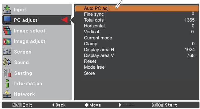
text_image
Input PC adjust Image select Image adjust Screen Sound Setting Information Network Auto PC adj. Fine sync 0 Total dots 1365 Horizontal 0 Vertical 0 Current mode Clamp 0 Display area H 1024 Display area V 768 Reset Mode free Store MENU Exit Back Move ---- SELECT StartManual PC Adjustment
Some computers employ special signal formats which may not be tuned by Multi-scan system of this projector. Manual PC Adjustment enables you to precisely adjust several parameters to match those signal formats. The projector has 10 independent memory areas to store those parameters manually adjusted. It allows you to recall the setting for a specific computer.
1 Press the MENU button to display the On-Screen Menu. Use the Point ▲▼ buttons to select PC adjust and then press the Point ▶ or the SELECT button.
2 Use the Point ▲▼ buttons to select the desired item and then press the SELECT button to display the adjustment dialog box. Use the Point ◀▶ buttons to adjust the setting value.
Fine sync
Use the Point ◀▶ buttons to adjust the value, eliminating a flicker from the image displayed (from 0 to 31).
Total dots
Use the Point ◀▶ buttons to adjust the number of total dots in one horizontal period to match your PC image.
Horizontal
Use the Point ◀▶ buttons to adjust the horizontal picture position.
Vertical
Use the Point ◀▶ buttons to adjust the vertical picture position.
Current mode
Press the SELECT button to show H-sync freq. and V-sync freq. of the connected computer.
Clamp
Use the Point ◀▶ buttons to adjust the clamp level. When the image has dark bars, try this adjustment.
Display area H
Use the Point ◀▶ buttons to adjust the horizontal area displayed by this projector.
Display area V
Use the Point ◀▶ buttons to adjust the vertical area displayed by this projector.
PC adjust Menu
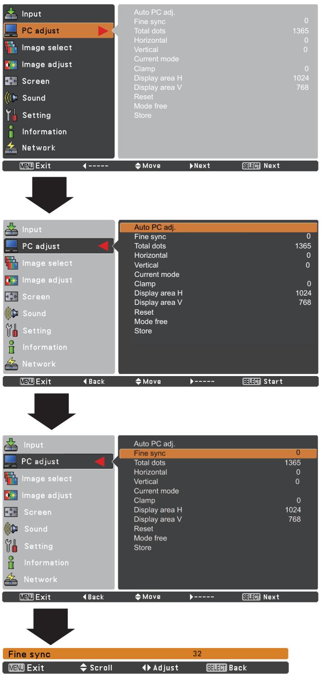
text_image
Input PC adjust Image select Image adjust Screen Sound Setting Information Network Auto PC adj. Fine sync 0 Total dots 1365 Horizontal 0 Vertical 0 Current mode Clamp 0 Display area H 1024 Display area V 768 Reset Mode free Store MENU Exit ←---- Move Next SELECT Next Input PC adjust Image select Image adjust Screen Sound Setting Information Network Auto PC adj. Fine sync 0 Total dots 1365 Horizontal 0 Vertical 0 Current mode Clamp 0 Display area H 1024 Display area V 768 Reset Mode free Store MENU Exit ← Back Move →---- SELECT Start Input PC adjust Image select Image adjust Screen Sound Setting Information Network Auto PC adj. Fine sync 0 Total dots 1365 Horizontal 0 Vertical 0 Current mode Clamp 0 Display area H 1024 Display area V 768 Reset Mode free Store MENU Exit ← Back Move ←---- SELECT Next Fine sync 32 MENU Exit ← Scroll Adjust Select BackReset
To reset the adjusted data, select Reset and press the SELECT button. A confirmation box appears and then select Yes. All adjustments will return to their previous figures.
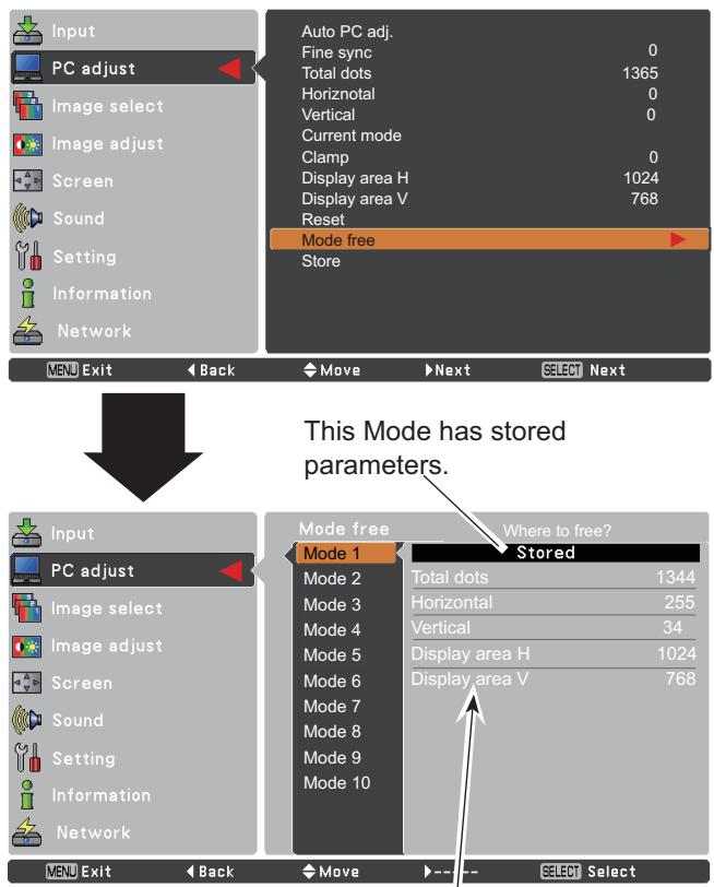
Mode free
To clear the stored data, select Mode free and then press the Point ▶ or the SELECT button. Move the highlight to the Mode that you want to clear and then press the SELECT button.
Store
To store the adjusted data, select Store and then press the Point ▶ or the SELECT button. Move the highlight to one of the Modes 1 to 10 in which you want to store, and then press the SELECT button.
Mode free
text_image
Input PC adjust Image select Image adjust Screen Sound Setting Information Network Auto PC adj. Fine sync 0 Total dots 1365 Horizontal 0 Vertical 0 Current mode Clamp 0 Display area H 1024 Display area V 768 Reset Mode free Store MENU Exit Back Move Next Select Next This Mode has stored parameters. Input PC adjust Image select Image adjust Screen Sound Setting Information Network Mode free Where to free? Mode 1 Stored Mode 2 Total dots 1344 Mode 3 Horizontal 255 Mode 4 Vertical 34 Mode 5 Display area H 1024 Mode 6 Display area V 768 Mode 7 Mode 8 Mode 9 Mode 10 MENU Exit Back Move Select SelectValues of Total dots, Horizontal, Vertical, Display area H, and Display area V.
Store
text_image
Input PC adjust Image select Image adjust Screen Sound Setting Information Network Store Mode 1 Mode 2 Mode 3 Mode 4 Mode 5 Mode 6 Mode 7 Mode 8 Mode 9 Mode 10 Where to store? Free Total dots 1344 Horizontal 255 Vertical 34 Display area H 1024 Display area V 768 MENU Exit Back Move SELECT Select Press MENU button to close this dialog box. Press SELECT button to store the data.√Note:
- Display area (H/V) cannot be selected when 480i, 576i, 480p, 576p, 720p, 1035i or 1080i is selected in the PC System Menu (p.28).
- When input computer signal to the projector, PC adjust will become available.
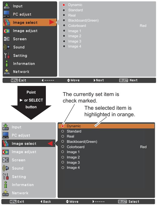
Image Mode Selection
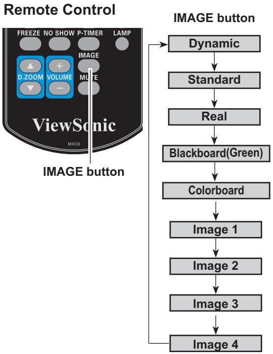
Direct Operation
Select the desired image mode among Dynamic, Standard, Real, Blackboard (Green), Colorboard, Image 1, Image 2, Image 3 and Image 4 by pressing the IMAGE button on the remote control.
Menu Operation
1 Press the MENU button to display the On-Screen Menu. Use the Point ▲▼ buttons to select Image select and then press the Point ▶ or the SELECT button.
2 Use the Point ▲▼ buttons to select the desired item and then press the SELECT button.
flowchart
graph TD
    A["ViewSonic"] --> B["IMAGE button"]
    B --> C["Dynamic"]
    C --> D["Standard"]
    D --> E["Real"]
    E --> F["Blackboard(Green)"]
    F --> G["Colorboard"]
    G --> H["Image 1"]
    H --> I["Image 2"]
    I --> J["Image 3"]
    J --> K["Image 4"]
Dynamic
For viewing pictures in a bright room.
Standard
Normal picture mode preset on the projector.
Real
Picture mode with improved halftone for graphics.
Blackboard (Green)
For the image projected on a blackboard.
This mode helps enhance the image projected on a blackboard. This is mainly effective on a green colored board, not truly effective on a black colored board.
Colorboard
At the time of simple projection on the colored wall, you can get the close color image to the color image projected on a white screen by selecting the similar color to the wall color from the preset four colors.
Image 1–4
For viewing with the user preset image mode in the Image Adjust Menu (see pages 33-34). This Image memory is provided in each computer, component, S-video and video input source.
Image select Menu
text_image
Input PC adjust Image select Image adjust Screen Sound Setting Information Network Dynamic Standard Real Blackboard(Green) Colorboard Image 1 Image 2 Image 3 Image 4 Red Menu Exit ← ---- ▶ Move ▶ Next ▶ SELECT Next Input PC adjust Image select Image adjust Screen Sound Setting Information Network Dynamic Standard Real Blackboard(Green) Colorboard Image 1 Image 2 Image 3 Image 4 Red Menu Exit ← Back ▶ Move ▶ ---- ▶ SELECT SelectImage Adjustment
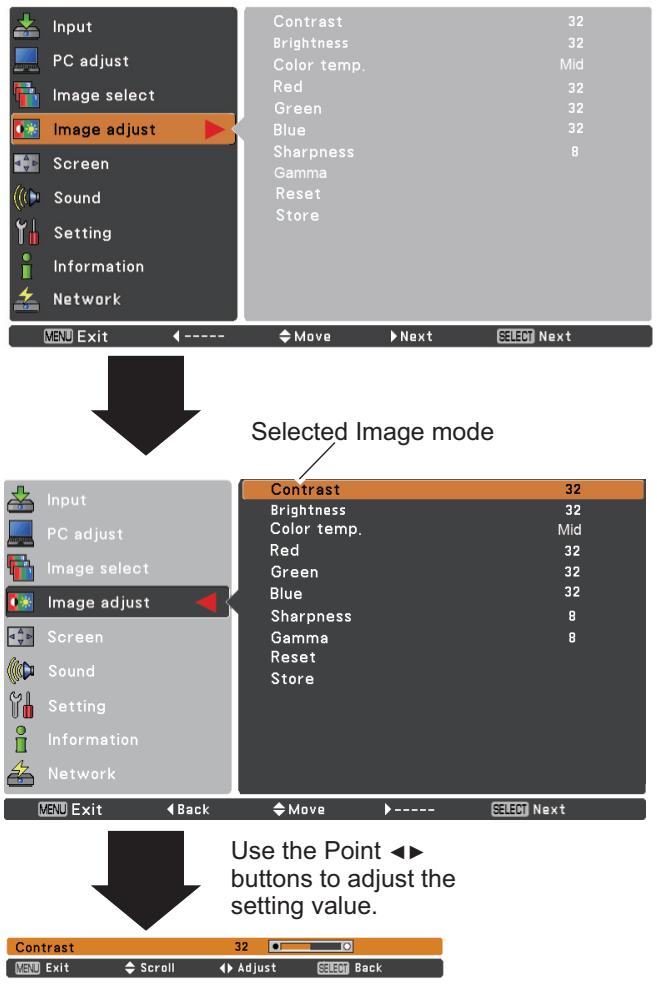
1 Press the MENU button to display the On-Screen Menu. Use the Point ▲▼ buttons to select Image adjust and then press the Point ▶or the SELECT button.
2 Use the Point ▲▼ buttons select the desired item and then press the SELECT button to display the adjustment dialog box. Use the Point ◀▶ buttons to adjust the setting value.
Contrast
Press the Point ◀ button to decrease the contrast; press the Point ▶ button to increase the contrast (from 0 to 63).
Brightness
Press the Point ◀ button to decrease the brightness; press the Point ▶ button to increase the brightness (from 0 to 63).
Color temp.
Use the Point ◀▶ buttons to select the desired Color temp. level (XLow, Low, Mid, or High).
White balance (Red)
Press the Point◀ button to lighten red tone; press the Point ▶ button to deepen red tone (from 0 to 63).
White balance (Green)
Press the Point ◀ button to lighten green tone; press the Point ▶ button to deepen green tone (from 0 to 63).
White balance (Blue)
Press the Point ◀ button to lighten blue tone; press the Point ▶ button to deepen blue tone (from 0 to 63).
Sharpness
Press the Point ◀ button to decrease the sharpness of the image; press the Point ▶ button to increase the sharpness of the image (from 0 to 15).
Gamma
Use the Point ◀▶ buttons to adjust the gamma value to obtain a better balance of contrast (from 0 to 15).
Reset
To reset the adjusted data, select Reset and press the SELECT button. A confirmation box appears and then select Yes. All adjustments will return to their previous figures.
Image Adjust Menu
text_image
Input PC adjust Image select Image adjust Screen Sound Setting Information Network Contrast 32 Brightness 32 Color temp. Mid Red 32 Green 32 Blue 32 Sharpness 8 Gamma Reset Store MENU Exit ←----→ Move →Next →SELECT Next Selected Image mode Input PC adjust Image select Image adjust Screen Sound Setting Information Network Contrast 32 Brightness 32 Color temp. Mid Red 32 Green 32 Blue 32 Sharpness 8 Gamma 8 Reset Store MENU Exit ←Back →Move →----→SELECT Next Use the Point ▶▶ buttons to adjust the setting value. Contrast 32 MENU Exit ← Scroll ▶Adjust →Select Back√Note:
- When White balance Red, Green or Blue is adjusted, Color temp. will change to User.
- When Blackboard(Green) or Colorboard is selected in Image select, Color temp. will change to Blackboard or Colorboard.
Store
To store the adjusted data, select Store and press the Point ▶ or the SELECT button. Use the Point ▲▼ buttons to select one from Image 1 to 4 and press the SELECT button. A confirmation box appears and then select Yes. Stored data can be called up by selecting an Image (1–4) in the Image Mode Selection on page 32.
Screen Size Adjustment
This projector has the picture screen resize function, which enables you to customize the image size.
1 Press the MENU button to display the On-Screen Menu. Use the Point ▲▼ buttons to select Screen and then press the Point ▶ or the SELECT button.
2 Use the Point ▲▼ buttons select the desired item and then press the SELECT button.
Normal
Provide the image to fit the screen size.
True
Provide the image in its original size. When the original image size is larger or smaller than the screen size (1024 x 768), the projector enters to the panning mode automatically. Use the Point ▲▼◀▶ buttons to pan the image. When adjusted, the arrows will turn red. When reached to the correction limits, the arrows will disappear.
Wide
Provide the image to fit the wide video aspect ratio (16:9) by expanding the image width uniformly. This function can be used for providing a squeezed video signal at 16:9.
Full
Provide the full screen image.
Custom
Provide the last stored aspect screen image.
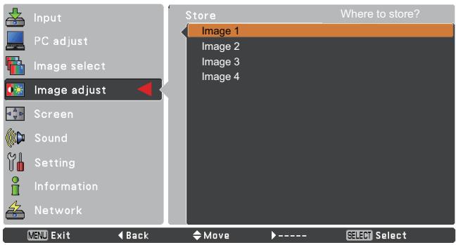
text_image
Input PC adjust Image select Image adjust Screen Sound Setting Information Network Store Where to store? Image 1 Image 2 Image 3 Image 4 MENU Exit Back Move ---- SELECT Select
text_image
OK? Yes No MENU Exit Move SELECT SelectA confirmation box appears and then select Yes.
Screen Menu
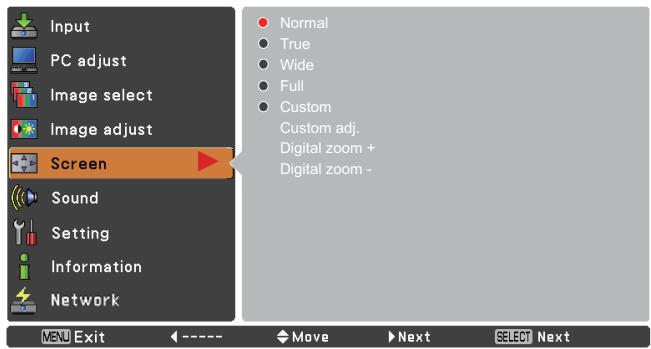
text_image
Input PC adjust Image select Image adjust Screen Sound Setting Information Network MENU Exit ← ---- → Move ▶ Next → SELECT Next Normal True Wide Full Custom Custom adj. Digital zoom + Digital zoom -
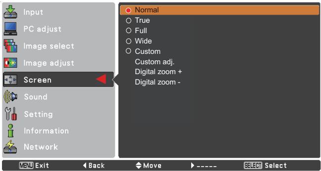
text_image
Input PC adjust Image select Image adjust Screen Sound Setting Information Network MENU Exit Back Move ---- SELECT Select Normal ○ True ○ Full ○ Wide ○ Custom Custom adj. Digital zoom + Digital zoom -√Note:
- The Screen Menu, only Normal and Custom can be operated, Wide will be disabled and displayed in gray when 720p, 1035i, or 1080i is selected in the PC System Menu (p.28).
- This projector cannot display any resolution higher than 1920 x 1200. If your computer's screen resolution is higher than it, reset the resolution to the lower before connecting to the projector.
- The image data in other than 1024 x 768 is modified to fit the screen size in initial mode.
- True, Full, and Digital zoom +/- are disabled and cannot be displayed when 480i, 576i, 480p or 576p is selected in the PC System Menu (p.28).
Custom adj.
Adjust the screen scale and position manually with this function.
Press the Point ▶ button at Custom adj. and the Custom adjustment menu is displayed on the screen, you can use the Point ▲▼ buttons to choose the item you want to adjust.
Scale H/V ...... Adjust the Horizontal/Vertical screen scale.
H&V...... When set to On, the aspect ratio is fixed. The Scale V appears dimmed and becomes unavailable. Adjust Scale H, then the screen scale is automatically modified based on the aspect ratio.
Position H/V ..... Adjust the Horizontal/Vertical screen position.
Common...... Save the adjusted scale or position to all the inputs. Press the SELECT button at Common to display a confirmation box. To save the scale or position, press the SELECT button at Yes. When Custom is selected, the saved scale or position is used.
Reset...... Reset the all adjusted values. Press the SELECT button at Reset to display a confirmation box. To reset, press the SELECT button at Yes.
For zooming in and out the images
Digital zoom +
Select Digital zoom +. The On-Screen Menu disappears and D. zoom + appears. Press the SELECT button to expand the image size. Use the Point ▲▼◀▶ buttons to pan the image. The Panning function can work only when the image is larger than the screen size.
A projected image can be also expanded by pressing the D.ZOOM ▲ or the SELECT button on the remote control.
Digital zoom –
Select Digital zoom –. The On-Screen Menu disappears and D. zoom – appears. Press the SELECT button to compress image size.
The projected image can be also compressed by pressing the D.ZOOM ▼ or the SELECT button on the remote control.
To exit the Digital zoom +/- mode, press any button except the D.ZOOM ▲▼ buttons, SELECT and Point buttons.
To return to the previous screen size, select a screen size from the Screen Size Adjustment Menu or select an input source from the Input Source Selection Menu (see page 27) again, or adjust the screen size with the D.ZOOM ▲▼ buttons.
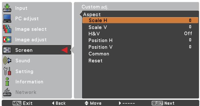
text_image
Input PC adjust Image select Image adjust Screen Sound Setting Information Network MENU Exit Back Move ---- SELECT Next Custom adj. Aspect Scale H 0 Scale V 0 H&V Off Position H 0 Position V 0 Common Reset

√Note:
- When no signal is detected, Normal is set automatically.
- The adjustable range for Scale H/V and Position H/V is limited depending on the input signal.
Remote Control
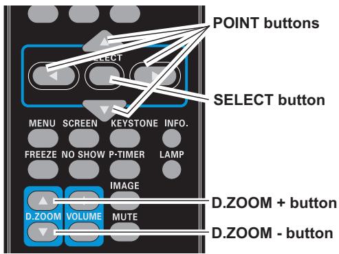
text_image
POINT buttons SELECT button MENU SCREEN KEYSTONE INFO. FREEZE NO SHOW P-TIMER LAMP IMAGE D.ZOOM + button D.ZOOM - button D.ZOOM VOLUME MUTE√Note:
- The minimum compression ratio is limited depending on the input signal, when the Keystone function is working or when the custom is selected for the screen size.
- True, Full, and Digital zoom +/- cannot be selected when 480i, 576i, 480p or 576p is selected in the PC System Menu (p.28).
- Digital zoom +/- cannot be selected when Full or True is selected.
- When Custom is selected, the Digital zoom - function is disabled.
Input Source Selection (Video, S-video)
Direct Operation
Choose Video or S-video by pressing the VIDEO or the S-VIDEO button on the remote control.
Before using these buttons, correct input source should be selected through menu operation as described below.
Remote Control
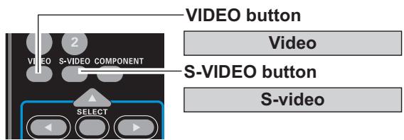
text_image
VIDEO button VIDEO S-VIDEO COMPONENT SELECT S-VIDEO button Video S-videoMenu Operation
1 Press the MENU button to display the On-Screen Menu. Use the Point ▲▼ buttons to select Input and then press the Point ▶ or the SELECT button.
2 Use the Point ▲▼buttons to select Video and then press the SELECT button.
Video When video input signal is connected to the VIDEO jack, select Video.
Input Menu
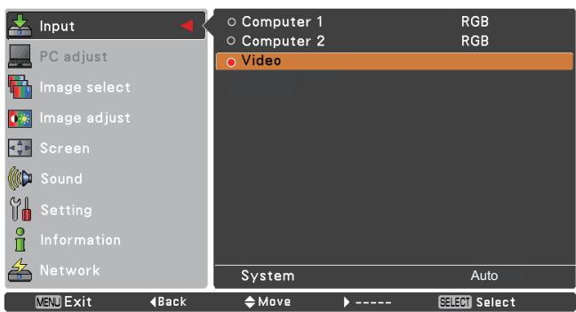
text_image
Input PC adjust Image select Image adjust Screen Sound Setting Information Network Computer 1 RGB Computer 2 RGB Video System Auto MENU Exit Back Move ---- SELECT SelectUse the Point ▲▼ buttons to select Computer 1. And then press the Point ▶ button to access the submenu items. Use the Point ▲▼ buttons to select the S-video and then press the SELECT button.
S-video When the input source is coming from video equipment connected to the COMPUTER IN 1/S-VIDEO IN/COMPONENT IN terminal with a S-video-VGA cable, select S-VIDEO.
√Note:
When the Input Search function is set to On1 or On2 in the Auto setup function, the input signal will be searched automatically (p.44).
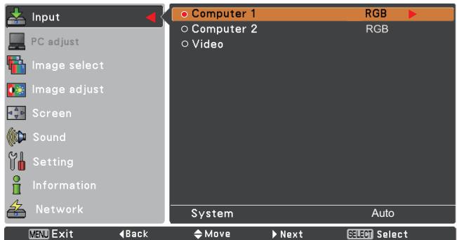
text_image
Input PC adjust Image select Image adjust Screen Sound Setting Information Network Computer 1 RGB Computer 2 RGB Video System Auto MENU Exit Back Move Next SELECT Select
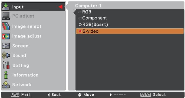
text_image
Input PC adjust Image select Image adjust Screen Sound Setting Information Network MENU Exit Back Move SELECT Select Computer 1 ○ RGB ○ Component ○ RGB(Scart) ● S-videoInput Source Selection (Component, RGB Scart 21-pin)
Direct Operation
Choose Computer 1(Component) or Computer 1(Scart) by pressing the COMPONENT or the COMPUTER 1 button on the remote control.
Before using these buttons, correct input source should be selected through Menu operation as described below.
Remote Control
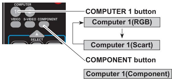
flowchart
graph TD
    A["COMPUTER 1 button"] --> B["COMPUTER 1(RGB)"]
    B --> C["COMPUTER 1(Scart)"]
    C --> D["COMPONENT button"]
    D --> E["COMPUTER 1(Component)"]
Menu Operation
1 Press the MENU button to display the On-Screen Menu. Use the Point ▲▼ buttons to select Input and then press the Point ▶ or the SELECT button.
2 Use the Point ▲▼ buttons to select Computer 1 and then press the Point ▶ button.
3 Use the Point ▲▼ buttons to select Component or RGB(Scart) and then press the SELECT button.
Component
When the input source is coming from video equipment connected to the COMPUTER IN 1/S-VIDEO IN/COMPONENT IN terminal with a Component-VGA Cable, select Component.
RGB (Scart)
When the input source is coming from video equipment connected to the COMPUTER IN 1/S-VIDEO IN/COMPONENT IN terminal with a Scart-VGA Cable, select RGB (Scart).
√Note:
When the Input Search function is set to On1 or On2, the input signal will be searched automatically (p.44).
Input Menu
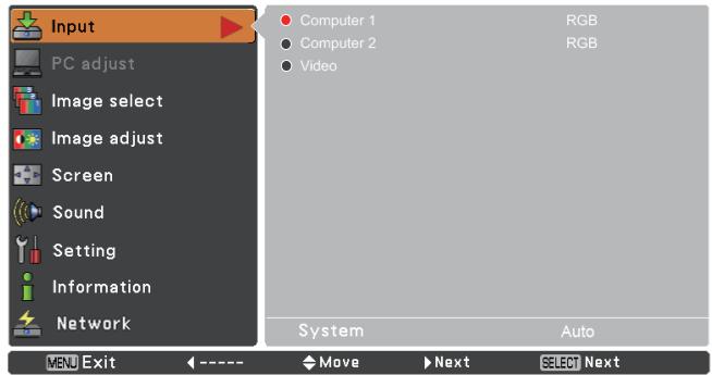
text_image
Input PC adjust Image select Image adjust Screen Sound Setting Information Network Computer 1 Computer 2 Video RGB RGB System Auto MENU Exit ← ---- Move ► Next SELECT Next
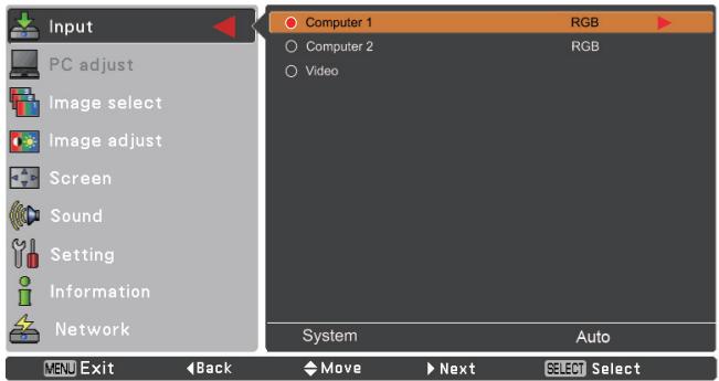
text_image
Input PC adjust Image select Image adjust Screen Sound Setting Information Network Computer 1 RGB Computer 2 RGB Video System Auto MENU Exit Back Move Next SELECT Select
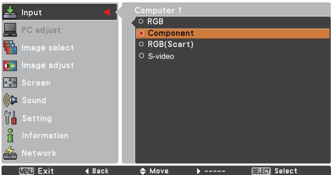
text_image
Input PC adjust Image select Image adjust Screen Sound Setting Information Network MENU Exit ← Back ← Move → ---- SELECT Select Computer 1 ○ RGB ○ Component ○ RGB(Scart) ○ S-videoVideo System Selection
1 Press the MENU button to display the On-Screen Menu. Use the Point ▲▼ buttons to select Input and then press the Point ▶ or the SELECT button.
2 Select Video, S-video or Computer 1(Component) input source. (See pages 36-37)
3 Use the Point ▲▼ buttons to select System and then press the Point ▶ or the SELECT button. Use the Point ▲▼ buttons to select the desired system and then press the SELECT button.
Video or S-video
Auto
The projector automatically detects an incoming video system, and adjusts itself to optimize its performance. When Video System is PAL-M or PAL-N, select the system manually.
PAL/SECAM/NTSC/NTSC4.43/PAL-M/PAL-N
If the projector cannot reproduce proper video image, select a specific broadcast signal format from among PAL, SECAM, NTSC, NTSC 4.43, PAL-M, and PAL-N.
AV System Menu (Video or S-video)
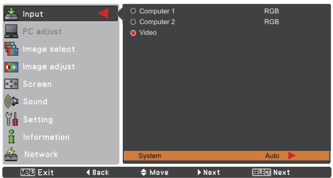
text_image
Input PC adjust Image select Image adjust Screen Sound Setting Information Network Computer 1 Computer 2 Video RGB RGB System Auto MENU Exit Back Move Next SELECT Next
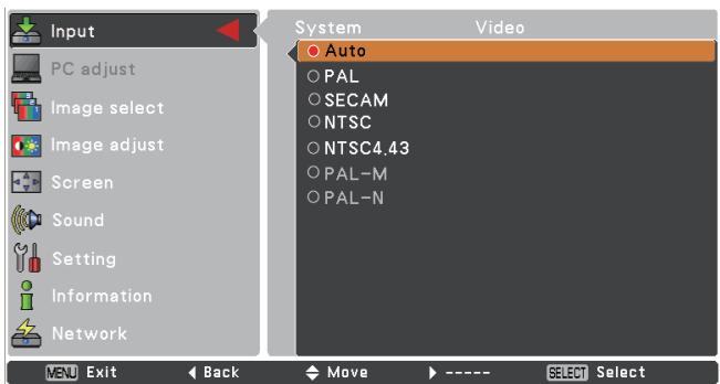
text_image
Input PC adjust Image select Image adjust Screen Sound Setting Information Network System Auto PAL SECAM NTSC NTSC4.43 PAL-M PAL-N Video MENU Exit Back Move ---- SELECT SelectComponent
Auto
The projector automatically detects an incoming video signal, and adjusts itself to optimize its performance.
COMPONENT VIDEO SIGNAL FORMAT
If the projector cannot reproduce proper video image, select a specific component video signal format from among 480i, 576i, 480p, 576p, 720p, 1035i, and 1080i.
√Note:
The AV System Menu cannot be selected when selecting RGB (Scart).
AV System Menu (Component)
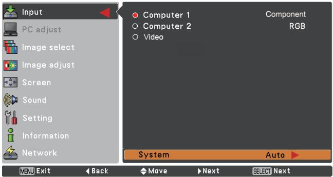
text_image
Input PC adjust Image select Image adjust Screen Sound Setting Information Network Computer 1 Computer 2 Video Component RGB System Auto MENU Exit Back Move Next SELECT Next
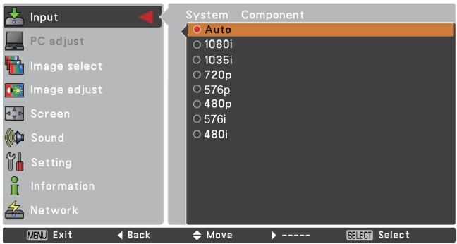
text_image
Input PC adjust Image select Image adjust Screen Sound Setting Information Network System Component Auto 1080i 1035i 720p 576p 480p 576i 480i MENU Exit Back Move ---- SELECT SelectImage Mode Selection
Direct Operation
Select the desired image mode among Dynamic, Standard, Cinema, Blackboard (Green), Colorboard, Image 1, Image 2, Image 3 and Image 4 by pressing the IMAGE button on the remote control.
Menu Operation
1 Press the MENU button to display the On-Screen Menu. Use the Point ▲▼ buttons to select Image select and then press the Point ▶ or the SELECT button.
2 Use the Point ▲▼ buttons to select the desired item and then press the SELECT button.
Remote Control
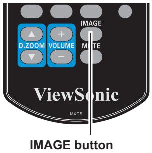
text_image
D.ZOOM VOLUME - IMAGE MITE ViewSonic MXCS IMAGE buttonIMAGE button
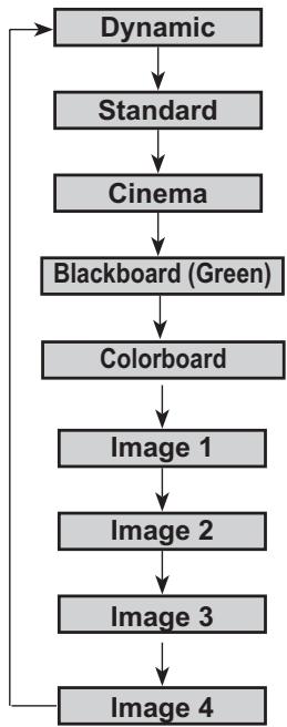
flowchart
graph TD
    A["Dynamic"] --> B["Standard"]
    B --> C["Cinema"]
    C --> D["Blackboard (Green)"]
    D --> E["Colorboard"]
    E --> F["Image 1"]
    F --> G["Image 2"]
    G --> H["Image 3"]
    H --> I["Image 4"]
Dynamic
For viewing pictures in a bright room.
Standard
Normal picture mode preset on the projector.
Cinema
Picture mode adjusted with fine tone.
Blackboard (Green)
For the image projected on a blackboard.
This mode help enhance the image projected on a blackboard. This is mainly effective on a green colored board, not truly effective on a black colored board.
Colorboard
At the time of simple projection on the colored wall, you can get the close color image to the color image projected on a white screen by selecting the similar color to the wall color from the preset four colors.
Image 1–4
For viewing with the user preset image mode in the Image Adjust Menu (see pages 40-41). This Image memory is provided in each computer, scart, component, S-video and video input source.
Image select Menu
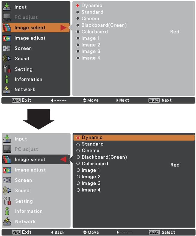
text_image
Input PC adjust Image select Image adjust Screen Sound Setting Information Network Dynamic Standard Cinema Blackboard(Green) Colorboard Image 1 Image 2 Image 3 Image 4 Red VENU Exit ← ---- ▶ Move ▶ Next ▶ SELECT Next Input PC adjust Image select Image adjust Screen Sound Setting Information Network Dynamic Standard Cinema Blackboard(Green) Colorboard Image 1 Image 2 Image 3 Image 4 Red VENU Exit ← Back ▶ Move ▶ ---- ▶ Select SelectImage Adjustment
1 Press the MENU button to display the On-Screen Menu. Use the Point ▲▼ buttons to select Image adjust and then press the Point ▶ or the SELECT button.
2 Use the Point ▲▼ buttons select the desired item and then press the SELECT button to display the adjustment dialog box. Use the Point ◀▶ buttons to adjust the setting value.
Contrast
Press the Point ◀ button to decrease the contrast; press the Point ▶ button to increase the contrast (from 0 to 63).
Brightness
Press the Point ◀ button to decrease the brightness; press the Point ▶ button to increase the brightness (from 0 to 63).
Color
Press the Point ◀ button decrease the intensity of the color; press the Point ▶ button increase the intensity of the color (from 0 to 63).
Tint
Press the Point ◀▶ buttons to adjust the tint value to get a proper color balance (from 0 to 63).
Color temp.
Use the Point ◀▶ buttons to select the desired Color temp. level (High, Mid, Low, or XLow).
White balance (Red)
Press the Point ◀ button to lighten red tone; press the Point ▶ button to deepen red tone (from 0 to 63).
White balance (Green)
Press the Point ◀ button to lighten green tone; press the Point ▶ button to deepen green tone (from 0 to 63).
White balance (Blue)
Press the Point ◀ button to lighten blue tone; press the Point ▶ button to deepen blue tone (from 0 to 63).
Image Adjust Menu
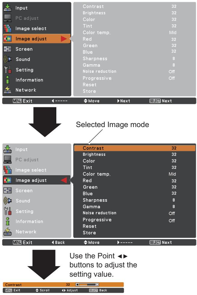
text_image
Input PC adjust Image select Image adjust Screen Sound Setting Information Network Contrast 32 Brightness 32 Color 32 Tint 32 Color temp. Mid Red 32 Green 32 Blue 32 Sharpness 8 Gamma 8 Noise reduction Off Progressive Off Reset Store Menu Exit ←---- Move Next SELECT Next Selected Image mode Input PC adjust Image select Image adjust Screen Sound Setting Information Network Contrast 32 Brightness 32 Color 32 Tint 32 Color temp. Mid Red 32 Green 32 Blue 32 Sharpness 8 Gamma 8 Noise reduction Off Progressive Off Reset Store Menu Exit ← Back Move ←---- SELECT Next Use the Point ←► buttons to adjust the setting value. Contrast 32√Note:
- When the White balance Red, Green or Blue is adjusted, the Color temp. level will change to User.
- Tint cannot be selected when the video system is PAL, SECAM, PAL-M or PAL-N (p.38).
- When Blackboard(Green) or Colorboard is selected in Image select, Color temp. will change to Blackboard or Colorboard.
Sharpness
Press the Point ◀ button to decrease the sharpness of the image; press the Point ▶ button to increase the sharpness of the image (from 0 to 15).
Gamma
Use the Point ◀▶ buttons to adjust the gamma value to obtain a better balance of contrast (from 0 to 15).
Noise reduction
Noise interference on the screen can be reduced. Select one of the following options to get smoother images.
Off ...... Disabled.
L1 ...... Lower reduction
L2 ...... Higher reduction
Progressive
An interlaced video signal can be displayed in progressive mode. Select one of the following options.
Off ...... Disabled.
L1 ...... For an active picture.
L2 ...... For a still picture.
Film ...... For watching a film. With this function, the projector reproduces pictures faithful to the original film quality.
Reset
To reset the adjusted data, select Reset and press the SELECT button. A confirmation box appears and then select Yes. All adjustments will return to their previous figures.
Store
To store the adjusted data, select Store and press the Point ▶ or the SELECT button. Use the Point ▲▼ buttons to select one from Image 1 to 4 and press the SELECT button. A confirmation box appears and then select Yes. Stored data can be called up by selecting an Image (1–4) in the Image Mode Selection on page 39.
√Note:
Noise reduction and Progressive cannot be selected when 480p, 576p, 720p, 1035i or 1080i is selected (p.38).
Store Menu
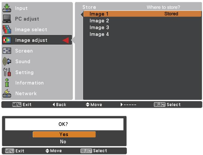
text_image
Input PC adjust Image select Image adjust Screen Sound Setting Information Network Store Where to store? Image 1 Stored Image 2 Image 3 Image 4 MENU Exit Back Move ---- SELECT Select OK? Yes No MENU Exit Move SELECT SelectA confirmation box appears and then select Yes.
Screen Size Adjustment
This projector has the picture screen resize function, which enables you to customize the image size.
1 Press the MENU button to display the On-Screen Menu. Use the Point ▲▼ buttons to select Screen and then press the Point ▶ or the SELECT button.
2 Use the Point ▲▼ buttons select the desired item and then press the SELECT button.
Normal
Provide the image to fit the screen size while maintaining the aspect ratio of the input signal.
Wide
Modify the 4:3 aspect ratio image to fit the screen size (16:9 aspect ratio) by stretching the image.
Custom
Provide the last stored aspect screen image.
Custom adj.
Adjust the screen scale and position manually with this function.
Press the Point ▶ button at Custom adj. and the Custom adjustment menu is displayed on the screen, you can use the Point ▲▼ buttons to choose the item you want to adjust.
Scale H/V ...... Adjust the Horizontal/Vertical screen scale.
H&V...... When set to On, the aspect ratio is fixed. The Scale V appears dimmed and becomes unavailable. Adjust Scale H, then the screen scale is automatically modified based on the aspect ratio.
Position H/V ..... Adjust the Horizontal/Vertical screen position.
Common...... Save the adjusted scale or position to all the inputs. Press the SELECT button at Common to display a confirmation box. To save the scale or position, press the SELECT button at Yes. When Custom is selected, the saved scale or position is used.
Reset...... Reset the all adjusted values. Press the SELECT button at Reset to display a confirmation box. To reset, press the SELECT button at Yes.
Screen Menu
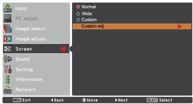
text_image
Input PC adjust Image select Image adjust Screen Sound Setting Information Network MEU Exit Back Move Next Select Select Normal Wide Custom Custom adj.
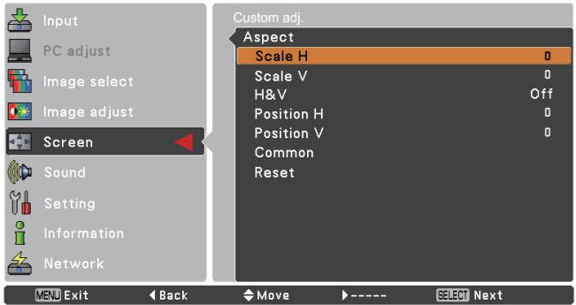
text_image
Input PC adjust Image select Image adjust Screen Sound Setting Information Network VENU Exit Back Move SELECT Next Custom adj. Aspect Scale H 0 Scale V 0 H&V Off Position H 0 Position V 0 Common Reset

√Note:
- When no signal is detected, Normal is set automatically.
- The adjustable range for Scale H/V and Position H/V is limited depending on the input signal.
- Wide cannot be operated when 720p, 1035i or 1080i is selected in the AV System Menu (p.38).
Setting
This projector has a Setting menu that allows you to set up the other various functions described below.
1 Press the MENU button to display the On-Screen Menu. Press the Point ▲▼ buttons to select Setting and press the Point ▶ or the SELECT button to access the submenu items.
2 Use the Point ▲▼ buttons to select the desired item and then press the Point ▶ or the SELECT button to access the selected item.
3 Use the Point ▲▼ buttons select the desired item and then press the SELECT button.
Setting Menu
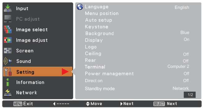
text_image
Input PC adjust Image select Image adjust Screen Sound Setting Information Network Language Menu position Auto setup Keystone Background Display Logo Ceiling Rear Terminal Power management Direct on Standby mode English Blue On Off Off Computer 2 Off Off Network 1/2 MENU Exit ← ---- ▼ Move ▶ Next SELECT Next
Language
The language used in the On-Screen Menu is available in English, German, French, Italian, Spanish, Portuguese, Dutch, Swedish, Finnish, Polish, Hungarian, Romanian, Russian, Turkish, Kazakh, Vietnamese, Chinese, Korean, Japanese and Thai.
Menu position
This function is used to change the position of the On-Screen Menu. Select Menu position and press the SELECT button.
The Menu position changes each time you press SELECT button as follows.
the top left → the top right → the center → the bottom left → the bottom right → the top left →.....
Language
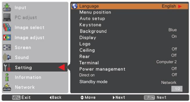
text_image
Input PC adjust Image select Image adjust Screen Sound Setting Information Network Language English ▶ Menu position Auto setup Keystone Background Blue Display On Logo Ceiling Off Rear Off Terminal Computer 2 Power management Off Direct on Off Standby mode Network 1/2 MENU Exit Back Move Next Select Next
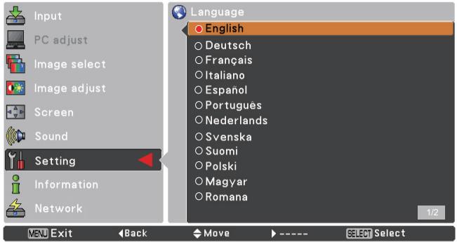
text_image
Input PC adjust Image select Image adjust Screen Sound Setting Information Network Language English Deutsch Français Italiano Español Portugues Nederlands Svenska Suomi Polski Magyar Romana 1/2 MENU Exit Back Move ---- SELECT SelectAuto setup
This function enables Input search, Auto Keystone correction and Auto PC adjustment by pressing the AUTO SETUP button on the top control or the AUTO SET button on the remote control. Settings for those functions can be altered as follows:
Input search
This function detects the input signal automatically. When a signal is found, the search will stop. Use the Point ▲▼ buttons to select one of the following options.
Off ...... Input search does not work.
On1..... Input search works under the following situation.
- When pressing the AUTO SETUP button on the top control.
- When pressing the AUTO SET button on the remote control.
On2...... Input search works under the following situation.
- When turning on the projector by pressing the ON/STAND-BY button on the top control or the remote control.
- When pressing the AUTO SET button on the remote control.
- When pressing the AUTO SETUP button on the top control.
- When the current input signal is cut off.*
* If the No show or Freeze function is active, cancel it to activate the Input search. It is also unavailable when On-Screen menu is displayed.
Auto PC adj.
On...... Enables Auto PC Adjustment when pressing the AUTO SET button on the remote control or the AUTO SETUP button on the top control.
Off...... Disables Auto PC Adjustment.
Auto Keystone
Auto...... Always works and corrects keystone distortion according to the projector's tilt.
Manual..... Works only when pressing the AUTO SETUP button on the top control or the AUTO SET button on the remote control.
Off...... Disables Auto Keystone.
√Note:
- While Input search is set to On1 or On2, the status of Input and Lamp are displayed every time the signal is switched.
- Only the last selected input source can be detected.
- During Input search is in progress, If the MENU button or the ON/STAND-BY button is pressed, Input search will stop. If the COMPUTER 1/2 button or VIDEO or COMPONENT or S-VIDEO button is pressed, Input search will stop and go back to the button's input signal.
- Input search, Auto PC adj. and Auto Keystone cannot be set Off at the same time.
Auto setup
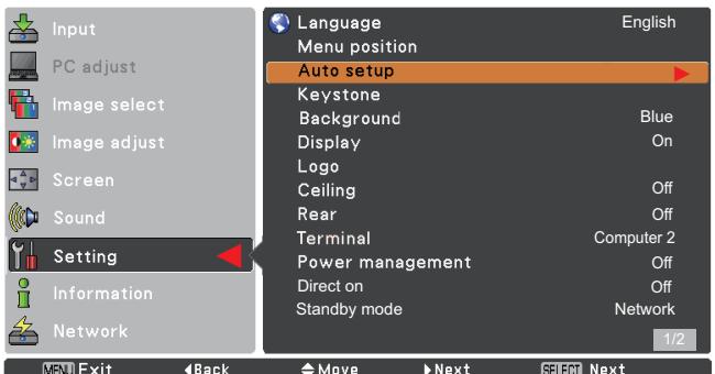
text_image
Input PC adjust Image select Image adjust Screen Sound Setting Information Network Language Menu position Auto setup Keystone Background Blue Display On Logo Ceiling Off Rear Off Terminal Computer 2 Power management Off Direct on Off Standby mode Network 1/2 MENU Exit Back Move Next SELECT Next
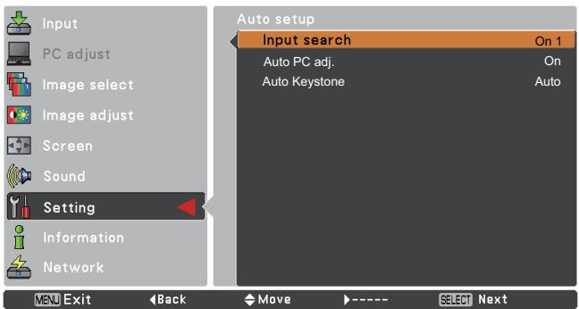
text_image
Input PC adjust Image select Image adjust Screen Sound Setting Information Network MENU Exit Back Move SELECT Next Auto setup Input search On 1 Auto PC adj. On Auto Keystone Auto
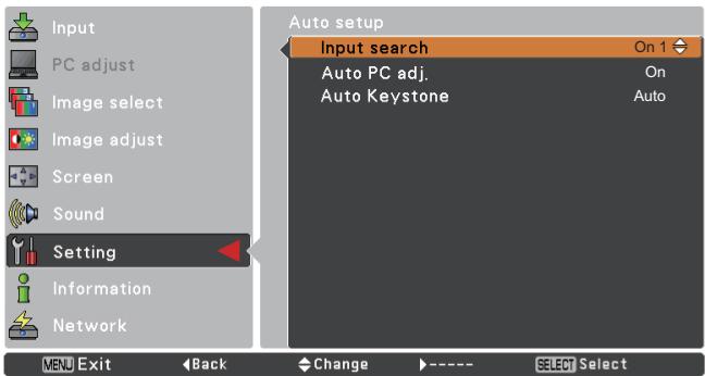
text_image
Input PC adjust Image select Image adjust Screen Sound Setting Information Network MENU Exit Back Change SELECT Select Auto setup Input search On 1 Auto PC adj. On Auto Keystone Auto√Note:
- Auto Keystone corrects vertical distortion only, not correct horizontal distortion.
- The Auto Keystone function cannot work when the Ceiling feature is set On in the Setting menu (p.49).
- Perfect correction of the image distortion cannot be ensured with the Auto setup function. If the distortion is not corrected properly by pressing the AUTO SETUP or the AUTO SET button, adjust manually by pressing the KEYSTONE button on the remote control or selecting Keystone in the Setting menu (pp.23, 45).
- Fine sync, Total dots, Horizontal and Vertical position of some computers cannot be fully adjusted with the Auto PC Adjustment function. When the image is not provided properly with this operation, manual adjustments are required (pp.30-31).
Keystone
This function is used to adjust keystone distortion of the projected image. Use the Point ▲▼ buttons to choose the item you want to adjust.
Keystone
To correct keystone distortion, press the SELECT button.
Keystone appears on the screen. Use the Point ▲▼ buttons to correct keystone distortion (p.23).
Store
Store .....Keep the keystone correction even when the AC power cord is unplugged.
Reset.....Release the keystone correction when the AC power cord is unplugged.
Background
Select the background screen for when no input signal is detected. Press the Point ▲▼ buttons to switch between each option.
Blue ... Project a blue background.
User . . . Project an image captured in the Logo setting.
Black .. Project a black background.
Display
This function decides whether to display On-Screen Displays.
On .... Show all the On-Screen displays. Use this function when you want to project images after the lamp becomes bright enough. The factory default setting is in this option.
Off ...... Hide the On-Screen Displays except;
- On-Screen Menu.
• Power off? (p.20) - P-Timer display. (p.26)
- No signal for Power management (p.50)
- Please wait ...
- Arrows for the True function in the Screen Menu. (p.34)
Keystone
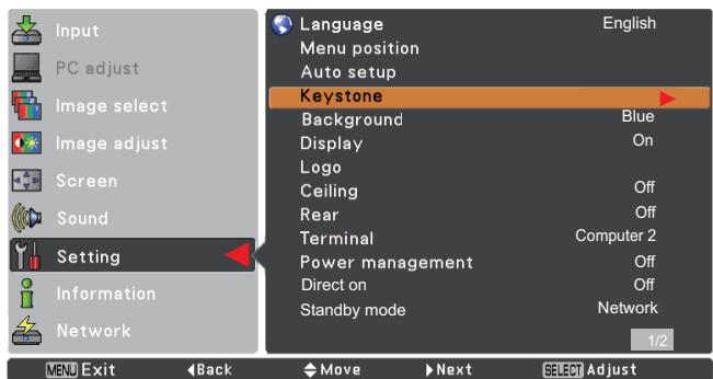
text_image
Input PC adjust Image select Image adjust Screen Sound Setting Information Network Language Menu position Auto setup Keystone Background Blue Display On Logo Ceiling Off Rear Off Terminal Computer 2 Power management Off Direct on Off Standby mode Network 1/2 MENU Exit Back Move Next SELECT Adjust
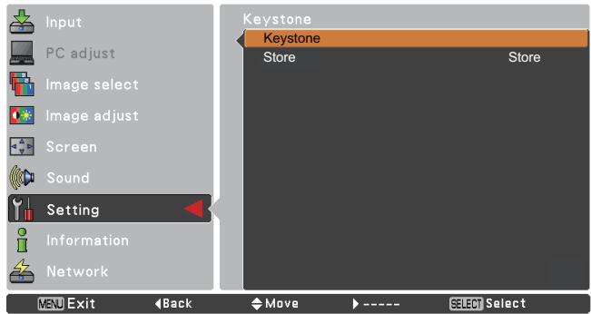
text_image
Input PC adjust Image select Image adjust Screen Sound Setting Information Network MENU Exit Back Move ---- SELECT Select Keystone Keystone Store StoreLogo (Logo and Logo PIN code lock settings)
This function allows you to customize the screen logo with Logo select, capture, Logo PIN code lock and Logo PIN code change functions.
√Note:
When On is selected in the Logo PIN code lock function, Logo select and Capture functions cannot be selected.
Logo select
This function decides on the starting-up display from among following options.
User ...... Show the image you captured.
Default .... Show the factory-set logo.
Off ...... Nothing is shown on the screen.
Logo select
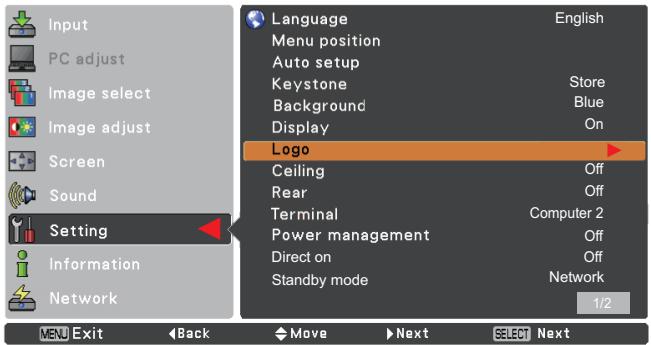
text_image
Input PC adjust Image select Image adjust Screen Sound Setting Information Network Language English Menu position Auto setup Keystone Store Background Blue Display On Logo Ceiling Off Rear Off Terminal Computer 2 Power management Off Direct on Off Standby mode Network 1/2 VEU Exit Back Move Next Select Next
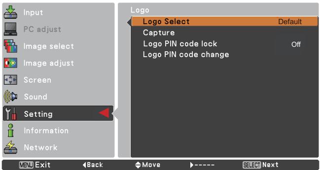
text_image
Input PC adjust Image select Image adjust Screen Sound Setting Information Network VEU Exit Back Move SELECT Next Logo Logo Select Default Capture Logo PIN code lock Off Logo PIN code change
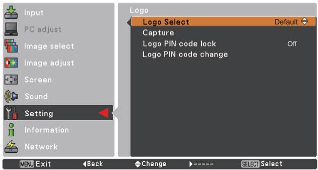
text_image
Input PC adjust Image select Image adjust Screen Sound Setting Information Network MENU Exit Back Change SELECT Select Logo Select Default Capture Logo PIN code lock Off Logo PIN code changeCapture
This function enables you to capture an image being projected to use it for a starting-up display or interval of presentations.
Select Capture and press the SELECT button.
A confirmation box appears and select Yes to capture the projected image.
After capturing the projected image, go to the Logo select function and set it to User. Then the captured image will be displayed the next time you turn on the projector or when you press the NO SHOW button. (see page 26)
To cancel the capture function, select Yes in the "Quit?" confirmation box.
√Note:
- Before capturing an image, select Standard in the Image select Menu to capture a proper image (pp.32, 39).
- A signal from a computer can be captured up to XGA (1024 x 768). A signal from video equipment can be captured except for 720p, 1035i, and 1080i.
- When capturing the image that has been adjusted by the Keystone function, the adjusted data is automatically reset and the projector captures an image without keystone correction.
- When Logo PIN code lock is set to On, capture cannot be selected.
- When starting to capture a new image, the previously stored image is cleared even if you cancel the capturing.
- When there is no captured image or it is interrupted while capturing an image, User cannot be selected, you can only switch between Default and Off.
Logo PIN code lock
This function prevents an unauthorized person from changing the screen logo.
Off ...... The screen logo can be changed freely from the Logo Menu (p.46).
On .... The screen logo cannot be changed without a Logo PIN code.
If you want to change the Logo PIN code lock setting, press the SELECT button and the Logo PIN code dialog box appears. Enter a Logo PIN code by following the steps below. The initial Logo PIN code is set to "4321" at the factory.
Capture
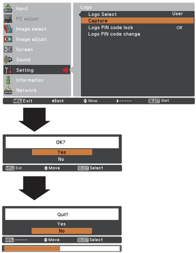
flowchart
graph TD
    A["Input"] --> B["PC adjust"]
    B --> C["Image select"]
    C --> D["Image adjust"]
    D --> E["Screen"]
    E --> F["Sound"]
    F --> G["Setting"]
    G --> H["Information"]
    H --> I["Network"]

    J["Logo Select User"] --> K["Capture"]
    K --> L["Logo PIN code lock Off"]
    L --> M["Logo PIN code change"]

    N["OK?"] --> O["Yes"]
    O --> P["No"]
    P --> Q["Menu Exit Move SELECT Select"]

    R["Quit?"] --> S["Yes"]
    S --> T["No"]
    T --> U["Menu ---- Move SELECT Select"]
Logo PIN code lock
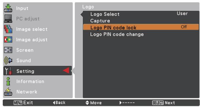
text_image
Input PC adjust Image select Image adjust Screen Sound Setting Information Network MENU Exit Back Move SELECT Next Logo Logo Select User Capture Logo PIN code lock Off Logo PIN code changeEnter a Logo PIN code
Use the Point ▲▼ buttons to enter a number. Press the Point ◀▶ buttons to fix the number and move the red frame pointer to the next box. The number changes to *. If you fixed an incorrect number, use the Point ◀▶ buttons to move the pointer to the number you want to correct, and then enter the correct number.
Repeat this step to complete entering a four-digit number.
After entering the four-digit number, move the pointer to Set. Press the SELECT button so that you can start to operate the projector.
If you entered an incorrect Logo PIN code, Logo PIN code and the number (****) will turn red for a moment. Enter the correct Logo PIN code all over again.
Change the Logo PIN code lock setting
Use the Point ▲▼ buttons to switch On or Off, and then press the SELECT button to make a choice.
Logo PIN code change
Logo PIN code can be changed to your desired four-digit number. Press the SELECT button to select Logo PIN code change. Current Logo PIN code dialog box appears, use the Point ▲▼buttons to enter the correct code. The New Logo PIN code input dialog box appears. Set a new Logo PIN code, confirmation box appears, choose Yes to set the new Logo PIN code.
Be sure to note the new Logo PIN code and keep it on hand. If you lost the number, you could no longer change the Logo PIN code setting.
Enter a Logo PIN code

text_image
Logo PIN code * Set Cancel MENU Cancel Adjust Move SELECT ----
After a correct Logo PIN code is entered, the following dialog box appears.
Change the Logo PIN code lock setting
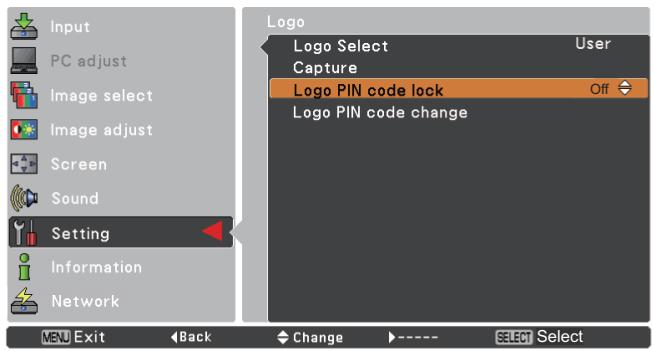
text_image
Input PC adjust Image select Image adjust Screen Sound Setting Information Network LOGO Logo Select User Capture Logo PIN code lock Off Logo PIN code change MENU Exit Back Change ---- SELECT SelectChange the Logo PIN code
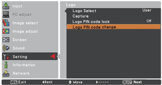
text_image
Input PC adjust Image select Image adjust Screen Sound Setting Information Network MEU Exit Back Move SELECT Next Logo Logo Select User Capture Logo PIN code lock Off Logo PIN code change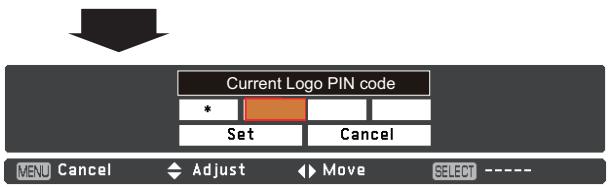
text_image
Current Logo PIN code Set Cancel MENU Cancel Adjust Move SELECT ----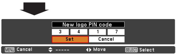
text_image
New logo PIN code 3 4 1 7 Set Cancel MENU Cancel ← ---- ▶ Move SELECT Select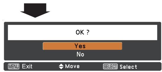
text_image
OK ? Yes No MENU Exit Move SELECT SelectCeiling
When this function is set to On, the picture will be top/bottom and left/right reversed. This function is used to project the image from a ceiling-mounted projector.
Rear
When this function is set to On, the picture will be left/right reversed. This function is used to project the image from rear of the screen.
Terminal
The COMPUTER IN 2/MONITOR OUT terminal on the back of the projector is switchable for computer input or monitor output. (See page 9) Select Computer 2 or Monitor Out with the Point ▲▼ buttons.
Computer 2 .. computer input
Monitor Out.. monitor out
Terminal function is not available when selecting Computer 2 to the input source. Change the input source to the others (Computer 1, and so on) so that the Terminal function will be available. (p.25, 36, 37)
Ceiling
flowchart
graph TD
    A["Line Graph"] --> B["Pie Chart"]
    style A fill:#f9f,stroke:#333
    style B fill:#bbf,stroke:#333
Rear
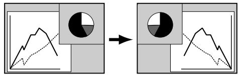
flowchart
graph TD
    A["Graph with solid black circles"] --> B["Circle graph with solid black circles"]
    style A fill:#f9f,stroke:#333
    style B fill:#bbf,stroke:#333
Terminal
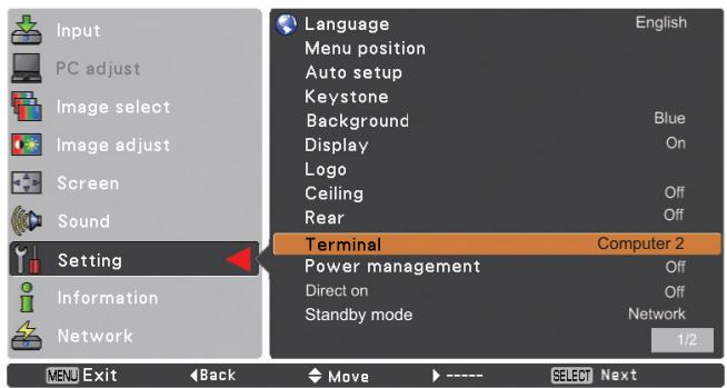
text_image
Input PC adjust Image select Image adjust Screen Sound Setting Information Network Language English Menu position Auto setup Keystone Background Blue Display On Logo Ceiling Off Rear Off Terminal Computer 2 Power management Off Direct on Off Standby mode Network 1/2 MENU Exit Back Move SELECT Next
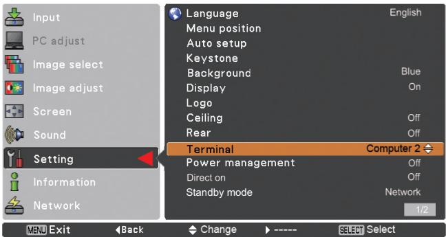
text_image
Input PC adjust Image select Image adjust Screen Sound Setting Information Network Language English Menu position Auto setup Keystone Background Blue Display On Logo Ceiling Off Rear Off Terminal Computer 2 Power management Off Direct on Off Standby mode Network 1/2 MENU Exit Back Change ---- SELECT SelectPower management
For reducing power consumption as well as maintaining the lamp life, the Power management function turns off the projection lamp when the projector is not operated for a certain period.
Select one of the following options:
Ready.... When the lamp has been fully cooled down, the POWER indicator changes to green blinking. In this condition, the projection lamp will be turned on if the input signal is reconnected or any button on the top control or remote control is pressed. Shut down..... When the lamp has been fully cooled down, the power will be turned off. Off.... Power management function is off. Timer..... If the input signal is interrupted and no button is pressed for more than 30 seconds, the timer display with No signal appears. It starts the countdown until the lamp is turned off. Use the Point ▲▼ buttons to set the Timer(1\~30min).
√Note:
Factory default is Ready: 5 min.
Direct on
When this function is set to On, the projector will be automatically turned on just by connecting the AC power cord to a wall outlet.
√Note:
Be sure to turn off the projector properly (see “Turning Off the Projector” on page 20). If the projector is turned off in the incorrect sequence, the Direct on function will not work properly.
Power management

text_image
No signal 04 : 50Time left before Lamp is off.
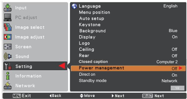
text_image
Input PC adjust Image select Image adjust Screen Sound Setting Information Network Language Menu position Auto setup Keystone Background Display Logo Ceiling Rear Closed caption Power management Off Direct on Standby mode English On Off Off Computer 2 On Network 1/2 MENU Exit Back Move Next SELECT Next
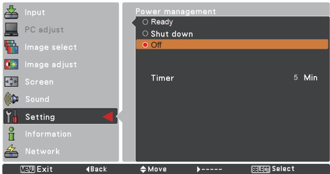
text_image
Input PC adjust Image select Image adjust Screen Sound Setting Information Network MENU Exit Back Move ---- SELECT Select Power management Ready Shut down Off Timer 5 Min
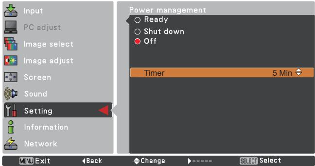
text_image
Input PC adjust Image select Image adjust Screen Sound Setting Information Network MENU Exit Back Change ---- SELECT Select Power management Ready Shut down Off Timer 5 MinStandby mode
This function is available when operating the projector via network.
Network .... Supply the power to the network function even after turning off the projector by pressing the ON/STAND-BY button on the remote control. You can turn on/off the projector via network, modify network environment, and receive an e-mail about projector status while the projector is powered off.
Eco...... Select Eco when you do not use the projector via network. The projector's network function will stop when turning off the projector, you can not turn on the projector via network.
Refer to the User Guide of "Network Set-up and Operation".
√Note:
- When selecting Network, the cooling fans may be running depending on the temperature inside the projector even if the projector is turned off.
- When Eco mode is selected and the projector is in Stand-by, the communication of RS-232C serial port is not available.
P-timer
This function allows you to change the setting of the P-timer and execute it.
Select one of the following options:
Count up ...... The P-timer display 000:00 appears on the screen and the count starts (000:00–180:00)
Count down...... The time set in the Timer setting appears on the screen and the countdown starts.
Timer..... Use the Point ▲▼ buttons to set the Timer (1–180 Min). Timer is available in Count down only. Factory default value is 10 Min.
Start...... It executes the count up or count down function. Press the SELECT button at Start and the indication changes into Stop. To stop Count up or Count down, press the SELECT button at Stop on the screen menu, then the indication changes into Restart. Press the SELECT button at Restart to resume Count up or Count down.
Reset .... Reset the P-timer values. Press the SELECT button at Reset to return to the following value; Count up ... "000:00" Count down ... Timer that you set Exit.... To exit the P-timer operation.
P-TIMER

002:00
P-timer display
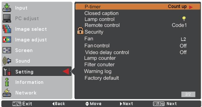
text_image
Input PC adjust Image select Image adjust Screen Sound Setting Information Network P-timer Count up Closed caption Lamp control Remote control Code1 Security Fan L2 Fan control Off Video delay control Off Lamp counter Filter conuter Warning log Factory default 2/2 MENU Exit Back Move Next Select Next

text_image
Input PC adjust Image select Image adjust Screen Sound Setting Information Network P-timer Count up Count down Timer Start Reset Exit 10 Min Exit Back Move SELECT Select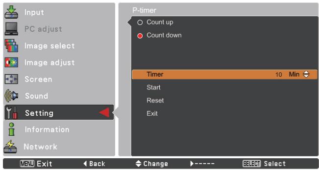
text_image
Input PC adjust Image select Image adjust Screen Sound Setting Information Network P-timer Count up Count down Timer 10 Min Start Reset Exit MENU Exit Back Change ---- SELECT SelectStop or Cancel the P-timer via Remote Control
To stop the P-timer, press the P-TIMER button.
To cancel the P-timer, press and hold the P-TIMER button for a few seconds.
Closed Caption
Closed Caption is a printed version of the program sound or other information displayed on the screen. If the input signal contains closed captions, you can turn on the feature and switch the channels. Press the Point ▲▼ buttons to select Off, CC1, CC2, CC3 or CC4.
If the closed caption is not clear, you can change the text from Color to White.
√Note:
The Closed Caption is available only under the situation below.
- When the input signal is Component (for adjustment only), Video or S-video, and the system is set to Auto, NTSC or 480i, the Closed caption is available.
- If the system is set to Auto, and choose NTSC or 480i as the input signal, the Closed caption will be available.
- Closed Caption will be unavailable when under other setting conditions.
- The Closed caption is unavailable when On-Screen menu and P-timer are displayed.
- The item of Closed Caption is displayed in gray while it is not available.
Closed Caption

text_image
Input PC adjust Image select Image adjust Screen Sound Setting Information Network P-timer Count up Closed caption Lamp control Remote control Code1 Security Fan L2 Fan control Off Video delay control Off Lamp counter Filter conuter Warning log Factory default 2/2 MENU Exit Back Move Next Select Next Input PC adjust Image select Image adjust Screen Sound Setting Information Network Closed caption Closed caption Off Color Color MENU Exit Back Move Next Select Next Input PC adjust Image select Image adjust Screen Sound Setting Information Network Closed caption Closed caption CC1 Color Color MENU Exit Back Change SELECT SelectPress the Point ▲▼ buttons to select Off, CC1, CC2, CC3 or CC4, and then press the SELECT button.
Lamp control
This function allows you to change brightness of the screen.
High...... Brighter than the Normal mode.
Normal..... Normal brightness
Eco .... Lower brightness reduces the lamp power consumption and extends the lamp life.
√Note:
Lamp mode cannot be changed for a while after turning on the projector. Lamp needs some time to stabilize after the power is turned on. Stored lamp mode will be active after the lamp is stabilized.
Lamp control
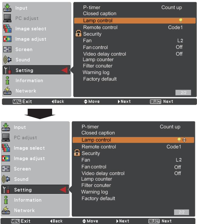
text_image
Input PC adjust Image select Image adjust Screen Sound Setting Information Network P-timer Count up Closed caption Lamp control Remote control Code1 Security Fan L2 Fan control Off Video delay control Off Lamp counter Filter conuter Warning log Factory default 2/2 MENU Exit Back Move Next SELECT Next Input PC adjust Image select Image adjust Screen Screen Sound Setting Information Network P-timer Count up Closed caption Lamp control Code1 Remote control Security Fan L2 Fan control Off Video delay control Off Lamp counter Filter conuter Warning log Factory default 2/2 MENU Exit Back Move Next Select NextRemote control
This projector provides two different remote control codes: the factory-set initial code (Code 1) and the secondary code (Code 2). This switching function prevents remote control interference when operating several projectors or video equipment at the same time.
When operating the projector in Code 2, both the projector and the remote control must be switched to Code 2.
To change the code for the projector:
Select either Code 1 or Code 2 in this Setting Menu.
To change the code for the remote control:
Press and hold both the MENU and IMAGE buttons together for 5 seconds or more. After changing the code, make sure the remote control operates properly.
Remote control

text_image
Input PC adjust Image select Image adjust Screen Sound Setting Information Network V3U Exit Back Move SELECT Select Remote control Code 1 Code 2√Note:
- When different codes are set on the projector and on the remote control, any operation cannot be made. In that case, switch the code on the remote control to fit the code on the projector.
- If the batteries are removed from the remote control for a long period of time, the remote control code will be reset.

Security (Key lock and PIN code lock)
This function allows you to use the Key lock and PIN code lock function to set the security for the projector operation.
Key lock
This function locks the top control and remote control buttons to prevent operation by unauthorized persons.
Select Key lock and then press the SELECT button, and select the desired item by pressing the Point ▲▼ buttons.

..... Unlocked.

..... Lock the operation of the top control. To unlock, use the remote control.

..... Lock the operation of the remote control. To unlock, use the top control.
If the top control accidentally becomes locked and you do not have the remote control nearby or there is something wrong with your remote control, contact the dealer where you purchased the projector or the service center.
PIN code lock
This function prevents the projector from being operated by unauthorized persons and provides the following setting options for security.
Off ...... Unlocked.
On1 ...... Enter the PIN code every time turning on the projector.
On2 ...... Enter the PIN code to operate the projector once the power cord is disconnected; as long as the AC power cord is connected, the projector can be operated without a PIN code.
Whenever you change the PIN code lock setting or the PIN code (the four-digit number), you are required to enter the PIN code. The “1234” is set as the initial PIN code at the factory.
If you want to change the PIN code lock setting, press the SELECT button and the PIN code dialog box appears.
When the projector is locked with the PIN code, the Security icon appears on the guide.
Key lock
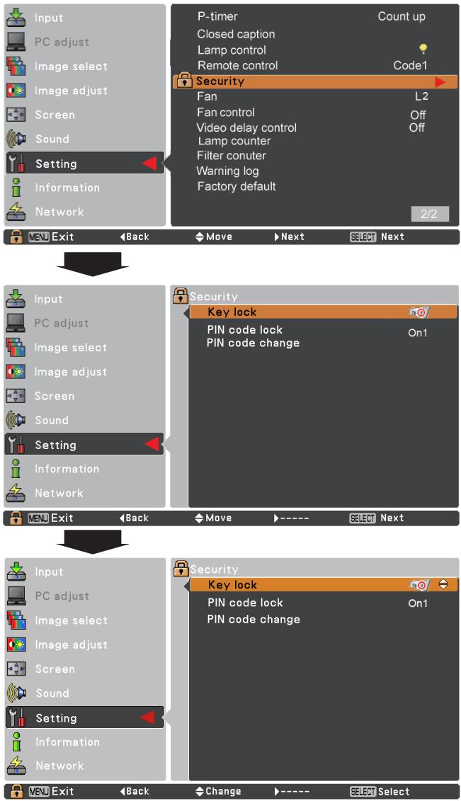
text_image
Input PC adjust Image select Image adjust Screen Sound Setting Information Network P-timer Count up Closed caption Lamp control Remote control Code1 Security Fan L2 Fan control Off Video delay control Off Lamp counter Filter conuter Warning log Factory default 2/2 VEU Exit Back Move Next SELECT Next Input PC adjust Image select Image adjust Screen Sound Setting Information Network VEU Exit Back Move Next Security Key lock PIN code lock On1 PIN code change VEU Exit Back Move Next Input PC adjust Image select Image adjust Screen Sound Setting Information Network Security Key lock PIN code lock On1 PIN code changePIN code lock
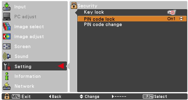
text_image
Input PC adjust Image select Image adjust Screen Sound Setting Information Network Security Key lock PIN code lock On1 PIN code change MENU Exit Back Change SELECT SelectEnter a PIN code
Use the Point ▲▼ buttons to enter a number. Press the Point ◀▶ buttons to fix the number and move the red frame pointer to the next box. The number changes to *. If you fixed an incorrect number, use the Point ◀▶ buttons to move the pointer to the number you want to correct, and then enter the correct number.
Repeat this step to complete entering a four-digit number.
After entering the four-digit number, move the pointer to Set. Press the SELECT button so that you can change the following PIN code lock setting.
If you entered an incorrect PIN code, PIN code and the number (****) will turn red for a moment. Enter the correct PIN code all over again.
Change the PIN code lock setting
Use the Point ▲▼ buttons to select Off, On1 or On2, and then press the SELECT button to make a choice.
Change the PIN code
The PIN code can be changed to your desired four-digit number. Press the SELECT button to select PIN code change. Pin code dialog box appears, use the Point ▲▼ buttons to enter the correct code. The New PIN code input dialog box appears. Set a new PIN code.
Enter a PIN code

text_image
PIN code * Set Cancel MENU Cancel Adjust Move SELECT ----Change the PIN code
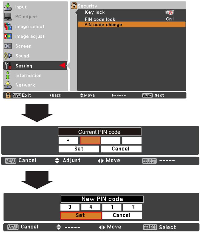
flowchart
graph TD
    A["Input"] --> B["PC adjust"]
    B --> C["Image select"]
    C --> D["Image adjust"]
    D --> E["Screen"]
    E --> F["Sound"]
    F --> G["Setting"]
    G --> H["Information"]
    H --> I["Network"]
    J["Security"] --> K["Key lock"]
    K --> L["PIN code lock On1"]
    L --> M["PIN code change"]
    N["Current PIN code"] --> O["*"]
    O --> P["Set"]
    O --> Q["Cancel"]
    R["New PIN code"] --> S["3 4 1 7"]
    S --> T["Set"]
    S --> U["Cancel"]
    V["Menu Cancel"] --> W["Adjust"] --> X["Move"] --> Y["SELECT ----"]
    Z["Menu Cancel"] --> AA["----"] --> AB["Move"] --> AC["SELECT Select"]
Fan
This function provides the following options in the cooling fans' operation when the projector is turned off (p.20).
L1 ..... The cooling fans rotate for about 60 seconds.
L2 ..... The cooling fans stop.
Fan control
Choose the running speed of cooling fans from the following options according to the ground elevation under which you use the projector.
Off...... Normal speed. Set this function to Off when using the projector in non-high altitude environment.
On1...... Faster than Off mode. Select this mode when using the projector in high altitudes (about 1,000 meters to 2,000 meters above the sea level) where the fans have less cooling effect.
On2.... Faster than On1 mode. Select this mode when using the projector in higher altitudes (about 2,000 meters to 3,000 meters above the sea level) where the fans have lesser cooling effect.
√Note:
The fan noise becomes louder in On1 and On2.
Video delay control
When you want to make a digital processing of a projected image faster, set this function.
Use the Point ▲▼ buttons, select an item of Off or On.
√Note:
Noise reduction and Progressive can not be selected when Video delay control is set to On.
Lamp counter
Be sure to reset the Lamp replacement counter after the lamp is replaced. (p. 62)
Press the Point ▲▼ buttons to choose the Lamp counter function and then press the Point ▶ or the SELECT button to access the submenu items.
Lamp counter......This item shows the total accumulated time of the lamp usage.
Lamp counter reset.....Press the SELECT button to choose Lamp counter reset. Select Yes in the confirmation box if you want to reset the lamp counter, and then choose Yes in the second confirmation box to reset lamp counter.
√Note:
When L2 is selected in Fan menu and the projector is turned on right after it turns off, it takes a while to start projecting.
Lamp counter reset
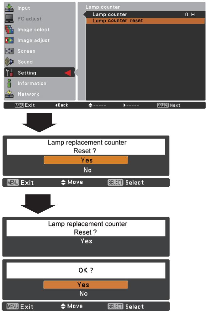
flowchart
graph TD
    A["Input"] --> B["PC adjust"]
    B --> C["Image select"]
    C --> D["Image adjust"]
    D --> E["Screen"]
    E --> F["Sound"]
    F --> G["Setting"]
    G --> H["Information"]
    H --> I["Network"]
    J["Lamp counter"] --> K["Lamp counter 0 H"]
    K --> L["Lamp counter reset"]
    M["Lamp replacement counter Reset ?"] --> N{Yes}
    N --> O{No}
    P["Lamp replacement counter Reset ?"] --> Q{Yes}
    Q --> R{OK ?}
    S["Yes"] --> T{No}
    U["MENU Exit"] --> V["Move"] --> W["SELECT Select"]
Filter counter
This function is used to set a frequency for the filter cleaning.
When the projector reached a specified time for cleanings, a Filter warning icon appears on the screen, notifying the cleaning is necessary. After cleaning the filter, be sure to select Reset and set the timer. The Filter warning icon will not turn off until the filter counter is reset.
For details about resetting the timer, refer to "Resetting the Filter Counter" on page 60.
Fig.1 Filter warning icon
Filter warning

Filter warning icon appears on the screen at a set time.
√Note:
This icon also appears at turning on.
√Note:
The Filter warning icon (Fig.1) will not appear when the Display function is set to Off (p.45), during Freeze(p.25), or No show (p.26).
Warning log
This function records anomalous operations while the projector is in operation and use it when diagnosing faults. Up to 10 warning logs are displayed with the latest warning message at the top of the list, followed by previous warning messages in chronological order.
√Note:
When the Factory default function is executed, all the warning log records will be deleted.
Factory default
This function returns all setting values except for the User logo, PIN code lock, Logo PIN code lock, Lamp counter and Filter counter to the factory default settings.
Filter counter
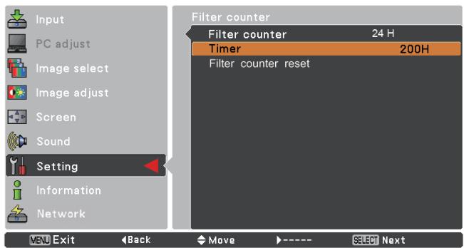
text_image
Input PC adjust Image select Image adjust Screen Sound Setting Information Network VBU Exit Back Move ---- SELECT Next Filter counter Filter counter 24 H Timer 200H Filter counter resetPress the SELECT button to select Timer, and then use the Point ▲▼ buttons to set the timer. Select from (Off/100H/200H/300H) depending on the use environment.
Factory default
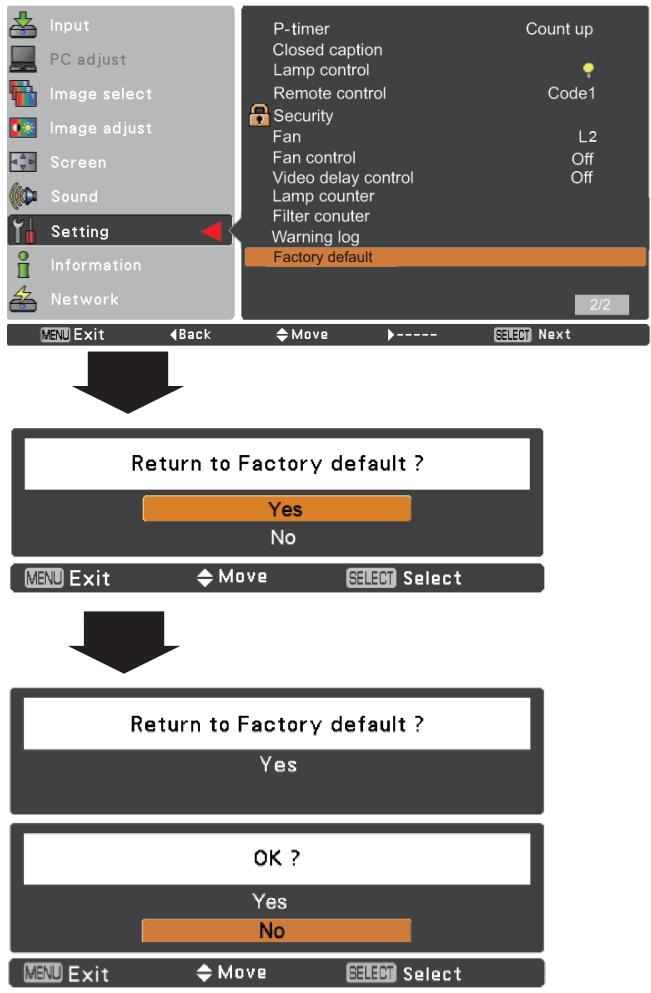
flowchart
graph TD
    A["Input"] --> B["PC adjust"]
    B --> C["Image select"]
    C --> D["Image adjust"]
    D --> E["Screen"]
    E --> F["Sound"]
    F --> G["Setting"]
    G --> H["Information"]
    H --> I["Network"]

    J["P-timer"] --> K["Count up"]
    K --> L["Closed caption"]
    L --> M["Lamp control"]
    M --> N["Remote control"]
    N --> O["Code1"]
    O --> P["Security"]
    P --> Q["Fan"]
    Q --> R["L2"]
    R --> S["Fan control"]
    S --> T["Off"]
    T --> U["Video delay control"]
    U --> V["Off"]
    V --> W["Lamp counter"]
    W --> X["Filter conuter"]
    X --> Y["Warning log"]
    Y --> Z["Factory default"]

    AA["Menu Exit"] --> AB["Back"]
    AB --> AC["Move"]
    AC --> AD["SELECT Next"]

    AE["Return to Factory default ?"] --> AF{Yes}
    AF --> AG{No}
    AG --> AH["MENU EXIT"]
    AH --> AI["Move"]
    AI --> AJ["SELECT Select"]

    AK["Return to Factory default ?"] --> AL{Yes}
    AL --> AM{No}
    AM --> AN["MENU EXIT"]
    AN --> AO["Move"]
    AO --> AP["SELECT Select"]
Input Source Information Display
The Information Menu is used for checking the status of the image signal being projected and the operation of the projector.
Direct Operation
Press the INFO. button on the remote control to display the Information Menu.
Menu Operation
Press the Point ▲▼ buttons to select the Information. The Information Menu is displayed.
See below for displayed information.
Input
The selected input source is displayed.
H-sync freq.
The horizontal frequency of the input signal is displayed in KHz, or - - - - KHz when no signal.
V-sync freq.
The vertical frequency of the input signal is displayed in Hz, or - - - - Hz when no signal. Numbers of Hz doubles when during Interlace.
Screen
The selected screen size is displayed.
Language
The selected language is displayed.
Lamp status
The selected lamp mode is displayed.
Lamp counter
The cumulative lamp operating time is displayed.
Power management
Off, Ready or Shut down, and Timer are displayed.
Key lock
The selected Key lock icon is displayed.
PIN code lock
Off or On1 or On2 is displayed.
Remote control
The selected remote code is displayed.
Remote Control
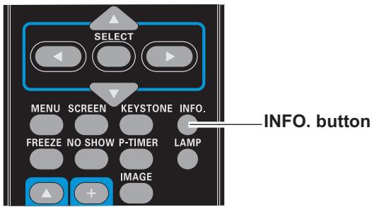
text_image
SELECT MENU SCREEN KEYSTONE INFO. FREEZE NO SHOW P-TIMER LAMP IMAGE INFO. buttonInformation Menu
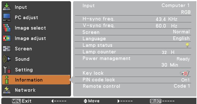
text_image
Input PC adjust Image select Image adjust Screen Sound Setting Information Network Input Computer 1 RGB H-sync freq. 43.4 KHz V-sync freq. 60.0 Hz Screen Normal Language English Lamp status Lamp counter 32 H Power management Ready 30 Min Key lock PIN code lock On1 Remote control Code 1 MENU Exit ←---- Move →---- SELECT ----WARNING indicator
The WARNING indicator shows the state of the function which protects the projector. Check the state of the WARNING indicator and the POWER indicator to take proper maintenance.
The projector is shut down and the WARNING indicator is blinking red.
When the temperature inside the projector reaches a certain level, the projector will be automatically shut down to protect the inside of the projector. The POWER indicator is blinking while the projector is being cooled down. When the projector has cooled down enough (to its normal operating temperature), it can be turned on again by pressing the ON/STAND-BY button.
√Note:
The WARNING indicator continues to blink even after the temperature inside the projector returns to normal. When the projector is turned on again, the WARNING indicator stops blinking.
Then check the matters below:
- Did you provide appropriate space for the projector to be ventilated? Check the installing condition to see if the air vents of the projector are not blocked.
- Has the projector been installed near an Air-Conditioning/ Heating Duct or Vent? Move the installation of the projector away from the duct or vent.
– Is the filter clean? Clean the filter periodically.
The projector is shut down and the WARNING indicator lights red.
When the projector detects an abnormal condition, it is automatically shut down to protect the inside of the projector and the WARNING indicator lights red. In this case, unplug the AC power cord and reconnect it, and then turn the projector on once again to verify operation. If the projector cannot be turned on and the WARNING indicator still lights red, unplug the AC power cord and contact the service center.

CAUTION
DO NOT LEAVE THE PROJECTOR WITH THE AC POWER CORD CONNECTED UNDER AN ABNORMAL CONDITION. IT MAY RESULT IN FIRE OR ELECTRIC SHOCK.
Top Control
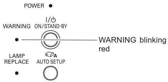
text_image
POWER WARNING ON/STAND-BY LAMP REPLACE AUTO SETUP I/O WARNING blinking redTop Control
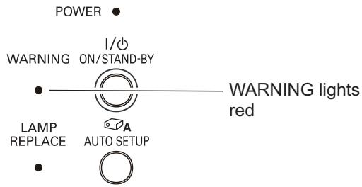
text_image
POWER WARNING ON/STAND-BY LAMP REPLACE AUTO SETUP I/O WARNING lights redCleaning the Filters
Filter prevents dust from accumulating on the optical elements inside the projector. Should the filters become clogged with dust particles, it will reduce cooling fans' effectiveness and may result in internal heat buildup and adversely affect the life of the projector. If a “Filter warning” icon appears on the screen, clean the filters immediately. Clean the filters by following the steps below.
1 Turn off the projector, and unplug the AC power cord from the AC outlet.
2 Remove the panel front assembly by pulling the latch horizontally.
Remove the panel net by pulling the latch horizontally and then remove it leftward.
3 Clean the filters with a brush or rinse them softly.
4 When cleaning the filters by rinsing, dry them well. Replace the filters properly. Make sure that the filters are fully inserted.

CAUTION
Do not operate the projector with the filter removed. Dust may accumulate on the optical elements degrading picture quality. Do not put anything into the air vents. Doing so may result in malfunction of the projector.
RECOMMENDATION
We recommend avoiding dusty/smoky environments when you operate the projector. Usage in these environments may cause poor image quality.
When using the projector under dusty or smoky conditions, dust may accumulate on a lens, LCD panels, or optical elements inside the projector degrading the quality of a projected image. When the symptoms above are noticed, contact your authorized dealer or service center for proper cleaning.
Resetting the Filter Counter
Be sure to reset the Filter counter after cleaning or replacing the filter.
1 Press the MENU button to display the On-Screen Menu. Use the Point ▲▼ buttons to select Setting and then press the Point ▶ or the SELECT button.
2 Use the Point ▲▼ buttons to select Filter counter and then press the Point ▶ or the SELECT button. Use the Point ▲▼ buttons to select Filter counter reset and then press the SELECT button. Filter counter Reset? appears. Select Yes to continue.
3 Another confirmation dialog box appears, select Yes to reset the Filter counter.
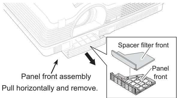
text_image
Panel front assembly Pull horizontally and remove. Spacer filter front Panel front√Note:
Please be sure to fit this edge when inserting this panel front assembly.
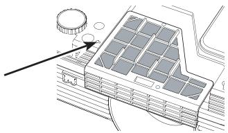
natural_image
Architectural diagram of a building facade with solar panels and a circular component (no text or symbols)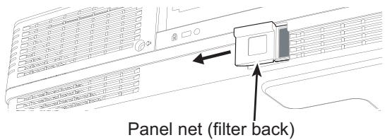
text_image
Panel net (filter back)Pull horizontally and then remove it leftward.
Filter counter
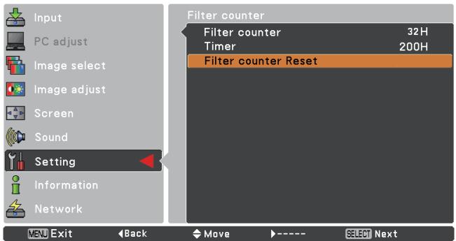
text_image
Input PC adjust Image select Image adjust Screen Sound Setting Information Network Filter counter Filter counter 32H Timer 200H Filter counter Reset MENU Exit Back Move ---- SELECT Next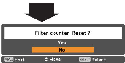
text_image
Filter counter Reset ? Yes No MENU Exit Move SELECT SelectFilter counter Reset? appears.

flowchart
graph TD
    A["Filter counter Reset?"] --> B["Yes"]
Select Yes, then another confirmation box appears.

text_image
OK ? Yes No MENU Exit Move SELECT SelectSelect Yes again to reset the Filter counter.
Attaching the Lens Cap
When moving this projector or while not using it over an extended period of time, replace the lens cap.
Attach the lens cap according to the following procedures.
1 Thread the string through the hole on the lens cap and then tie a knot in the string to secure it in place.
2 To pass the other end of the string into the hole on the bottom of the projector and pull at it.
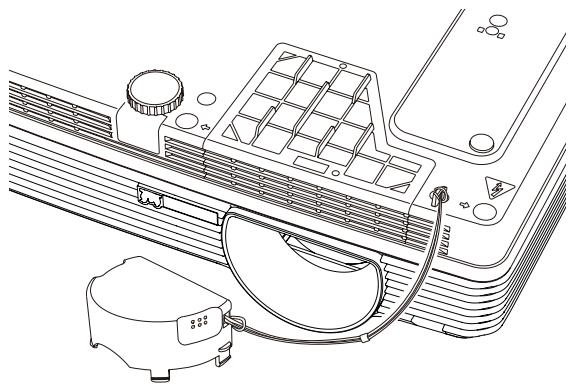
natural_image
Technical line drawing of a car air conditioner unit with cooling fan and fan assembly (no text or symbols)Cleaning the Projection Lens
Unplug the AC power cord before cleaning.
Gently wipe the projection lens with a cleaning cloth that contains a small amount of non-abrasive camera lens cleaner, or use a lens cleaning paper or commercially available air blower to clean the lens.
Avoid using an excessive amount of cleaner. Abrasive cleaners, solvents, or other harsh chemicals might scratch the surface of the lens.
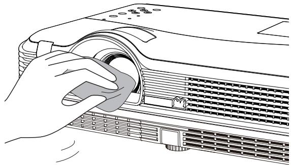
natural_image
Illustration of a hand inserting a component into a projector (no text or symbols visible)Cleaning the Projector Cabinet
Unplug the AC power cord before cleaning.
Gently wipe the projector body with a soft dry cleaning cloth. When the cabinet is heavily soiled, use a small amount of mild detergent and finish with a soft dry cleaning cloth. Avoid using an excessive amount of cleaner. Abrasive cleaners, solvents, or other harsh chemicals might scratch the surface of the cabinet.
When the projector is not in use, put the projector in an appropriate carrying case to protect it from dust and scratches.
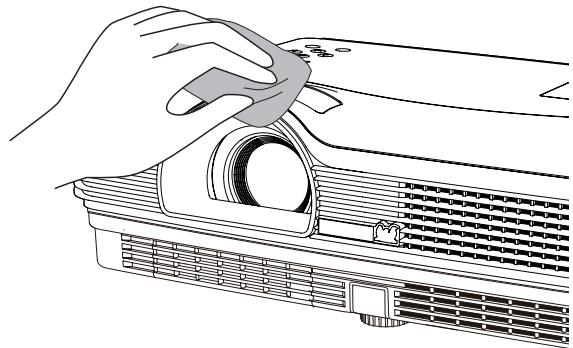
natural_image
Line drawing of a hand holding a clip next to a projector (no text or symbols)
CAUTION
Do not use any flammable solvents or air sprays on the projector and in its vicinity. The explosion or fire hazard may occur even after the AC power cord is unplugged because the temperature inside the projector is extremely high due to the lamps. In addition, there is a risk that the internal parts may be damaged not only by the flammable air spray but also by the cold air.
Lamp Replacement
When the projection lamp of the projector reaches its end of life, the Lamp replacement icon appears on the screen and LAMP REPLACE indicator lights yellow. Replace the lamp with a new one promptly. The timing when the LAMP REPLACE indicator should light is depending on the lamp mode.
Top Control
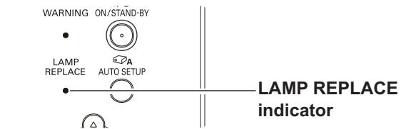
text_image
WARNING ON/STAND-BY LAMP REPLACE AUTO SETUP LAMP REPLACE indicatorLamp replacement icon
Lamp replacement

√Note:
The Lamp replacement icon will not appear when the Display function is set to Off (p.45), during Freeze (p.25), or No show (p.26).

CAUTION
Allow a projector to cool for at least 45 minutes before you open the Lamp Cover. The inside of the projector can become very hot.

CAUTION
For continued safety, replace with a lamp of the same type. Do not drop a lamp or touch a glass bulb! The glass can shatter and may cause injury.

CAUTION
When replacing the lamp because it has stopped illuminating, there is a possibility that the lamp may be broken.
If replacing the lamp of a projector which has been installed on the ceiling, you should always assume that the lamp is broken, and you should stand to the side of the lamp cover, not underneath it. Remove the lamp cover gently. Small pieces of glass may fall out when the lamp cover is opened. If pieces of glass get into your eyes or mouth, seek medical advice immediately.
Follow these steps to replace the lamp.
1 Unplug the AC power cord. Let the projector cool for at least 45 minutes.
2 Loosen the screw and open the lamp cover.
3 Loosen the three (3) screws that secure the lamp. Lift the lamp out of the projector by using the handles.
4 Replace the lamp with a new one and secure the three (3) screws. Make sure that the lamp is set properly. Close the lamp cover and secure the screw.
5 Connect the AC power cord to the projector and turn on the projector.
6 Reset the lamp replacement counter. See "Lamp Counter" on page 56.
Lamp Cover
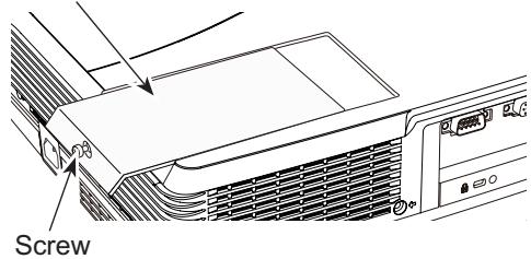
text_image
ScrewScrew
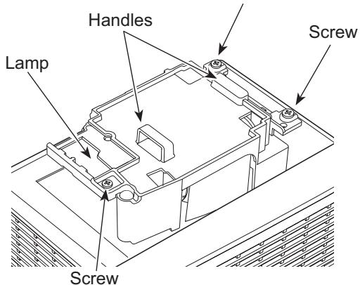
text_image
Handles Lamp Screw ScrewORDER REPLACEMENT LAMP
Replacement lamp can be ordered through your dealer. When ordering a projection lamp, give the following information to the dealer.
• Model No. of your projector : PJL6223, PJL6233
- Replacement Lamp Type No. : RLC-065

LAMP HANDLING PRECAUTIONS
This projector uses a high-pressure lamp which must be handled carefully and properly. Improper handling may result in accidents, injury, or create a fire hazard.
- Lamp life may differ from lamp to lamp and according to the environment of use. There is no guarantee of the same life for each lamp. Some lamps may fail or terminate their life in a shorter period of time than other similar lamps.
- If the projector indicates that the lamp should be replaced, i.e., if the LAMP REPLACE indicator lights up, replace the lamp with a new one IMMEDIATELY after the projector has cooled down. (Follow carefully the instructions in the Lamp Replacement section of this manual.) Continuous use of the lamp with the LAMP REPLACE indicator lighted may increase the risk of lamp explosion.
- A Lamp may explode as a result of vibration, shock or degradation as a result of hours of use as its lifetime draws to an end. Risk of explosion may differ according to the environment or conditions in which the projector and lamp are being used.
IF A LAMP EXPLODES, THE FOLLOWING SAFETY PRECAUTIONS SHOULD BE TAKEN.
If a lamp explodes, disconnect the projector's AC plug from the AC outlet immediately. Contact an authorized service center for a checkup of the unit and replacement of the lamp. Additionally, check carefully to ensure that there are no broken shards or pieces of glass around the projector or coming out from the cooling air circulation holes. Any broken shards found should be cleaned up carefully. No one should check the inside of the projector except those who are authorized trained technicians and who are familiar with projector service. Inappropriate attempts to service the unit by anyone, especially those who are not appropriately trained to do so, may result in an accident or injury caused by pieces of broken glass.
Troubleshooting
Before calling your dealer or service center for assistance, check the items below once again.
—Make sure you have properly connected the projector to peripheral equipment as described on pages 14-16.
–Make sure all equipment is connected to AC outlet and the power is turned on.
- When the projector does not project an image from the connected computer, restart the computer.
| Problem: | - Solutions |
| No power | - Plug the power cord of the projector into the AC outlet.- See if the POWER indicator lights red.- The projector can be turned on after the POWER indicator turns red. See page 18.- Check the WARNING indicator. If the WARNING indicator lights red, projector cannot be turned on. See page 59.- Check the projection lamp. See page 62.- Unlock the Key lock function for the projector. See page 54. |
| The initial display is not shown. | - Make sure Off is not chosen at display function. See page 45. |
| The initial display is not same as the default set. | - Make sure User or Off are not chosen at Logo (select) function. See page 46. |
| Input signal switches automatically. (or does not switch automatically) | - Make sure Input search function is adjusted properly. See page 44. |
| When the projector is on and you press the input source buttons, an icon other than the Lamp mode icon appears. | - That is the Filter warning icon. See page 57. |
| An icon other than Input mode or Lamp mode icon appears. | - That is the Lamp replacement icon or the Filter warning icon. See pages 57 or 62. |
| Image is out of focus. | - Adjust focus of the projector. See page 23.- Provide proper distance between the projector and the projection screen. See page 13.- Check the projection lens to see if it needs cleaning. See page 61.- Moving the projector from a cool to warm place may result in moisture condensation on the projection lens. In such cases, leave the projector off and wait until condensation evaporates. |
| Image is Left/Right reversed. Image is Top/Bottom reversed. | - Check the Ceiling/Rear function. See page 49.- Check the Ceiling function. See page 49. |
| Picture is not bright enough. | - Check if the Contrast or Brightness is adjusted properly. See pages 33, 40.- Check if Image mode is selected properly. See pages 32, 39.- Check the lamp control function. See pages 25, 53.- Check the LAMP REPLACE indicator. If it lights, the end of lamp life is approaching. Replace the lamp with a new one promptly. See page 62. |
| No image | - Check the connection between your computer or video equipment and the projector. See pages 14-16.- See if the input signal is correctly output from your computer. Some laptop computers may need to change the setting for monitor output when connecting to a projector. See your computer's instruction manual for the setting.- Check the Input signal, color system, video system or computer system mode.- Make sure the temperature is not out of the specified Operating Temperature (41°F–95°F [5°C–35°C]).- When No Show is operating, the image cannot be displayed. Press the NO SHOW button or any other button on the remote control. |
| No sound | - Check the audio cable connection from audio input source.- Adjust the audio source.- Press the Volume + button. See page 24.- Press the Mute button. See page 24.- When the AUDIO OUT is plugged-in, the projector's built-in speaker is not available.- Is the image projected? You will hear the sound only when the image is projected. |
| The color is strange. | - Check the Input signal, color system,video system or computer system mode.- Make sure the Blackboard is not selected on Image select menu. See pages 32, 39. |
| Some displays are not seen during the operation. | - Check the Display function. See page 45. |
| Auto PC adjustment function does not work. | - Check the Input signal. Auto PC adjustment function can not work when 480p,576p.720p,480i,576i,1035i or 1080i is selected. See page 29. |
| The setting does not remain after turning off power. | - Make sure you selected Store after adjusting setting. Some settings can not be stored if not registered with Store. See pages 34, 41. |
| Power management does not work. | - Power management function can not work while Freeze or No Show function is running. See page 50. |
| Capture function does not work. | - Check the connection and the input signal to see if there is signal. |
| Auto setup does not work properly. | - Make sure Off is not selected at any function of Auto setup. See page 44.- Make sure On is not selected at the Ceiling function. See page 49. |
| Auto keystone function does not work even when the projector is tipped. | - Make sure the Auto keystone function is not set to Manual. Press the AUTO SETUP button on the top control. See pages 23, 44. |
| The image is distorted or runs off. | - Check PC adjust menu or Screen menu and adjust them. See pages 30-31, 34-35. |
| PIN code dialog box appears at start-up. | - PIN code lock is being set. Enter a PIN code (the “1234” or numbers you have set). See pages 19, 54-55. |
| The Remote Control does not work. | - Check the batteries.- Make sure no obstruction is between the projector and remote control.- Make sure you are not too far from the projector when using the remote control. Maximum operating range is 16.4'(5 m).- Make sure the code of the remote control is conformed to the projector's code. See page 53.- Unlock the Key lock function for the remote control function. See page 54. |
| Indicator blinks or lights. | - Check the status of the projector with referring to "Indicators and projector Condition". See page 69. |
| The exclamation mark appears on the screen. | - Your operation is invalid. Operate correctly. |
| Top control does not work. | - The top control is not available if the top control is locked at Key lock under Security of SETTING section. See page 54. |
| Unable to unlock the Logo PIN code lock, Security key lock or Security PIN code lock. | - Contact the dealer where you purchased the projector or the service center. |
WARNING :
High voltages are used to operate this projector. Do not attempt to open the cabinet.
If problems still persist after following all operating instructions, contact the dealer where you purchased the projector or the service center. Specify the model number and explain about the problem. We will advise you how to obtain service.
Menu Tree
Computer Input/Video Input
Input
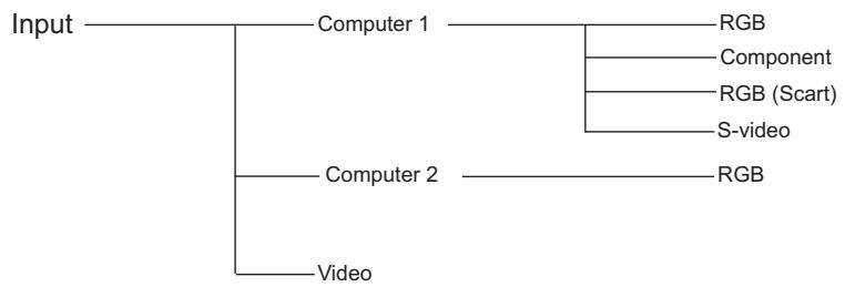
flowchart
graph TD
    A["Input"] --> B["Computer 1"]
    A --> C["Computer 2"]
    A --> D["Video"]
    B --> E["RGB"]
    B --> F["Component"]
    B --> G["RGB (Scart)"]
    B --> H["S-video"]
    C --> I["RGB"]
Sound

Computer Input
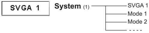
flowchart
graph TD
    A["SVGA 1"] --> B["System (1)"]
    B --> C["Mode 1"]
    B --> D["Mode 2"]
    B --> E["..."]
* Systems displayed in the System Menu vary depending on an input signal.
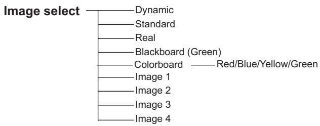
flowchart
graph TD
    A["Image select"] --> B["Dynamic"]
    A --> C["Standard"]
    A --> D["Real"]
    A --> E["Blackboard (Green)"]
    A --> F["Colorboard"]
    F --> G["Red/Blue/Yellow/Green"]
    F --> H["Image 1"]
    F --> I["Image 2"]
    F --> J["Image 3"]
    F --> K["Image 4"]
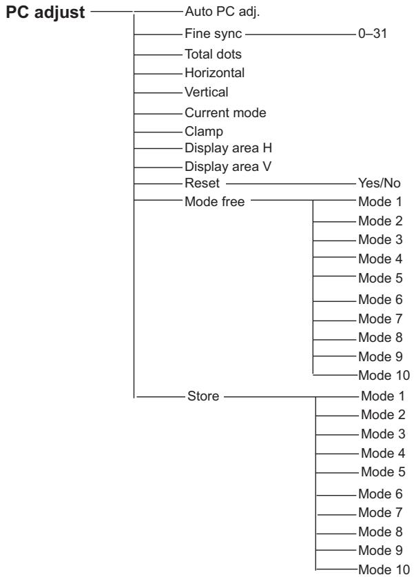
flowchart
graph TD
    A["PC adjust"] --> B["Auto PC adj."]
    B --> C["Fine sync 0-31"]
    C --> D["Total dots"]
    D --> E["Horizontal"]
    E --> F["Vertical"]
    F --> G["Current mode"]
    G --> H["Clamp"]
    H --> I["Display area H"]
    I --> J["Display area V"]
    J --> K["Reset Yes/No"]
    K --> L["Mode free Mode 1"]
    L --> M["Store Mode 1"]
    M --> N["Mode 2"]
    N --> O["Mode 3"]
    O --> P["Mode 4"]
    P --> Q["Mode 5"]
    Q --> R["Mode 6"]
    R --> S["Mode 7"]
    S --> T["Mode 8"]
    T --> U["Mode 9"]
    U --> V["Mode 10"]
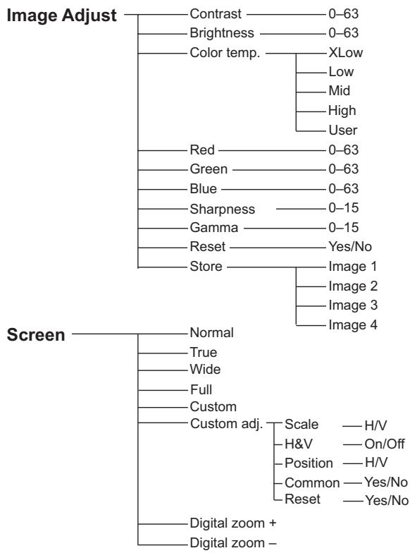
flowchart
graph TD
    A["Image Adjust"] --> B["Contrast 0-63"]
    A --> C["Brightness 0-63"]
    A --> D["Color temp. XLow"]
    D --> E["Low"]
    D --> F["Mid"]
    D --> G["High"]
    D --> H["User"]
    A --> I["Red 0-63"]
    A --> J["Green 0-63"]
    A --> K["Blue 0-63"]
    A --> L["Sharpness 0-15"]
    A --> M["Gamma 0-15"]
    A --> N["Reset Yes/No"]
    A --> O["Store Image 1"]
    O --> P["Image 2"]
    O --> Q["Image 3"]
    O --> R["Image 4"]
    S["Screen"] --> T["Normal"]
    S --> U["True"]
    S --> V["Wide"]
    S --> W["Full"]
    S --> X["Custom"]
    S --> Y["Custom adj. Scale H/V H&V On/Off Position H/V Common Yes/No Reset Yes/No"]
    Y --> Z["Digital zoom + Digital zoom -"]
Video Input
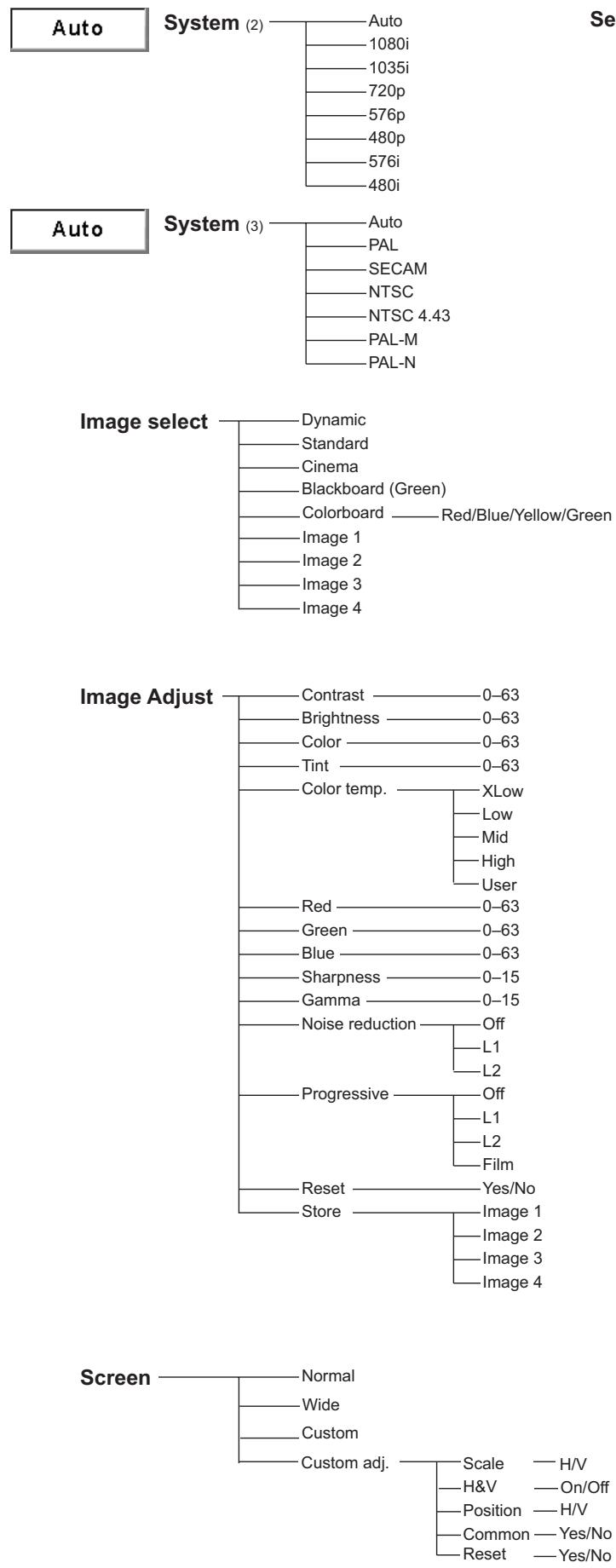
Setting
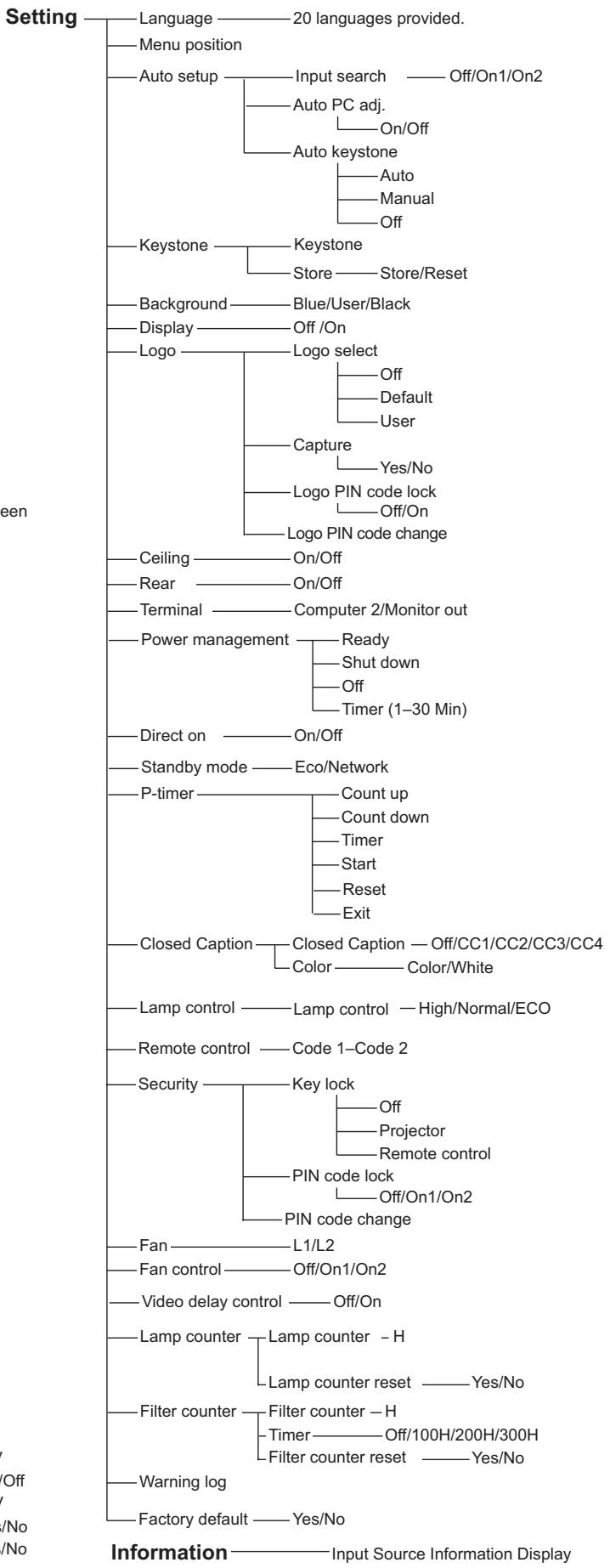
Indicators and Projector Condition
Check the indicators for projector condition.
| Indicators | Projector Condition | ||
| POWER red/green | WARNING red | LAMP REPLACE yellow | |
 |  |  | The projector is off. (The AC power cord is unplugged.) |
 | [SCWA] | * | The projector is in stand-by mode. Press the ON/STAND-BY button to turn on the projector. |
 | [5BB0] | * | The projector is operating normally. |
 | [A3T2] | * | The projector is preparing for stand-by or the projection lamp is being cooled down. The projector cannot be turned on until cooling is completed and the POWER indicator stops blinking. |
| [24ZA] |  | * | The projector is in the Power management mode. |
| [X20T] |  | * | The temperature inside the projector is abnormally high. The projector cannot be turned on. When the projector is cooled down enough and the temperature returns to normal, the POWER indicator stops blinking and the projector can be turned on. (The WARNING indicator keeps blinking.) |
| [AD06] |  | * | The projector has been cooled down enough and the temperature returns to normal. When turning on the projector, the WARNING indicator stops blinking. |
| [Y2Y7] |  | * | The projector detects an abnormal condition and cannot be turned on. Unplug the AC power cord and plug it again to turn on the projector. If the projector is turned off again, unplug the AC power cord and contact the dealer or the service center for service and checkup. Do not leave the projector on. It may cause an electric shock or a fire hazard. |
○ · · · green.
● · · · red
● · · · off
○ ••• blinks green.
••• blinks red.
*When the projection lamp reaches its end of life, the LAMP REPLACE indicator lights yellow. When this indicator lights yellow, replace the projection lamp with a new one promptly. (pp. 56, 62)
Compatible Computer Specifications
Basically this projector can accept the signal from all computers with the V-, H-Frequency mentioned below and less than 140 MHz of Dot Clock.
When selecting these modes, PC adjustment can be limited.
| ON-SCREEN DISPLAY | RESOLUTION | H-Freq. (KHz) | V-Freq. (Hz) | ON-SCREEN DISPLAY | RESOLUTION | H-Freq. (KHz) | V-Freq. (Hz) |
| VGA 1 | 640 x 480 | 31.47 | 59.88 | SXGA 5 | 1280 x 1024 | 63.74 | 60.01 |
| VGA 2 | 720 x 400 | 31.47 | 70.09 | SXGA 6 | 1280 x 1024 | 71.69 | 67.19 |
| VGA 3 | 640 x 400 | 31.47 | 70.09 | SXGA 7 | 1280 x 1024 | 81.13 | 76.107 |
| VGA 4 | 640 x 480 | 37.86 | 74.38 | SXGA 8 | 1280 x 1024 | 63.98 | 60.02 |
| VGA 5 | 640 x 480 | 37.86 | 72.81 | SXGA 9 | 1280 x 1024 | 79.976 | 75.025 |
| VGA 6 | 640 x 480 | 37.50 | 75.00 | SXGA 10 | 1280 x 960 | 60.00 | 60.00 |
| VGA 7 | 640 x 480 | 43.269 | 85.00 | SXGA 11 | 1152 x 900 | 61.20 | 65.20 |
| MAC LC13 | 640 x 480 | 34.97 | 66.60 | SXGA 12 | 1152 x 900 | 71.40 | 75.60 |
| MAC 13 | 640 x 480 | 35.00 | 66.67 | SXGA 13 | 1280 x 1024 | 50.00 | 86.00 (Interface) |
| 480p | 640 x 480 | 31.47 | 59.88 | SXGA 14 | 1280 x 1024 | 50.00 | 94.00 (Interface) |
| 576p | 768 x 576 | 31.25 | 50.00 | SXGA 15 | 1280 x 1024 | 63.37 | 60.01 |
| 480i | 640 x 480 | 15.734 | 60.00 (Interface) | SXGA 16 | 1280 x 1024 | 76.97 | 72.00 |
| 576i | 768 x 576 | 15.625 | 50.00 (Interface) | SXGA 17 | 1152 x 900 | 61.85 | 66.00 |
| SVGA 1 | 800 x 600 | 35.156 | 56.25 | SXGA 18 | 1280 x 1024 | 46.43 | 86.70 (Interface) |
| SVGA 2 | 800 x 600 | 37.88 | 60.32 | SXGA 19 | 1280 x 1024 | 63.79 | 60.18 |
| SVGA 3 | 800 x 600 | 46.875 | 75.00 | SXGA 20 | 1280 x 1024 | 91.146 | 85.024 |
| SVGA 4 | 800 x 600 | 53.674 | 85.06 | SXGA+ 1 | 1400 x 1050 | 63.97 | 60.19 |
| SVGA 5 | 800 x 600 | 48.08 | 72.19 | SXGA+ 2 | 1400 x 1050 | 65.35 | 60.12 |
| SVGA 6 | 800 x 600 | 37.90 | 61.03 | SXGA+ 3 | 1400 x 1050 | 65.12 | 59.90 |
| SVGA 7 | 800 x 600 | 34.50 | 55.38 | MAC21 | 1152 x 870 | 68.68 | 75.06 |
| SVGA 8 | 800 x 600 | 38.00 | 60.51 | MAC | 1280 x 960 | 75.00 | 75.08 |
| SVGA 9 | 800 x 600 | 38.60 | 60.31 | MAC | 1280 x 1024 | 80.00 | 75.08 |
| SVGA 10 | 800 x 600 | 32.70 | 51.09 | WXGA 1 | 1366 x 768 | 48.36 | 60.00 |
| SVGA 11 | 800 x 600 | 38.00 | 60.51 | WXGA 2 | 1360 x 768 | 47.70 | 60.00 |
| MAC 16 | 832 x 624 | 49.72 | 74.55 | WXGA 3 | 1376 x 768 | 48.36 | 60.00 |
| MAC 19 | 1024 x 768 | 60.24 | 75.08 | WXGA 4 | 1360 x 768 | 56.16 | 72.00 |
| XGA 1 | 1024 x 768 | 48.36 | 60.00 | WXGA 6 | 1280 x 768 | 47.776 | 59.87 |
| XGA 2 | 1024 x 768 | 68.677 | 84.997 | WXGA 7 | 1280 x 768 | 60.289 | 74.893 |
| XGA 3 | 1024 x 768 | 60.023 | 75.03 | WXGA 8 | 1280 x 768 | 68.633 | 84.837 |
| XGA 4 | 1024 x 768 | 56.476 | 70.07 | WXGA 9 | 1280 x 800 | 49.600 | 60.050 |
| XGA 5 | 1024 x 768 | 60.31 | 74.92 | WXGA 10 | 1280 x 800 | 41.200 | 50.000 |
| XGA 6 | 1024 x 768 | 48.50 | 60.02 | WXGA 11 | 1280 x 800 | 49.702 | 59.810 |
| XGA 7 | 1024 x 768 | 44.00 | 54.58 | WXGA 12 | 1280 x 800 | 63.98 | 60.02 |
| XGA 8 | 1024 x 768 | 63.48 | 79.35 | WUXGA 1 | 1920 x 1200 | 74.556 | 59.885 |
| XGA 9 | 1024 x 768 | 36.00 | 87.17 (Interface) | WUXGA 2 | 1920 x 1200 | 74.038 | 59.950 |
| XGA 10 | 1024 x 768 | 62.04 | 77.07 | WSXGA+ 1 | 1680 x 1050 | 65.290 | 59.954 |
| XGA 11 | 1024 x 768 | 61.00 | 75.70 | WXGA+ 1 | 1440 x 900 | 55.935 | 59.887 |
| XGA 12 | 1024 x 768 | 35.522 | 86.96 (Interface) | WXGA+ 2 | 1440 x 900 | 74.918 | 60.000 |
| XGA 13 | 1024 x 768 | 46.90 | 58.20 | UXGA 1 | 1600 x 1200 | 75.00 | 60.00 |
| XGA 14 | 1024 x 768 | 47.00 | 58.30 | UXGA 2 | 1600 x 1200 | 81.25 | 65.00 |
| XGA 15 | 1024 x 768 | 58.03 | 72.00 | UXGA 3 | 1600 x 1200 | 87.5 | 70.00 |
| SXGA 1 | 1152 x 864 | 64.20 | 70.40 | UXGA 4 | 1600 x 1200 | 93.75 | 75.00 |
| SXGA 2 | 1280 x 1024 | 62.50 | 58.60 | 720p | 1280 x 720 | 45.00 | 60.00 |
| SXGA 3 | 1280 x 1024 | 63.90 | 60.00 | 720p | 1280 x 720 | 37.50 | 50.00 |
| SXGA 4 | 1280 x 1024 | 63.34 | 59.98 | 1035i | 1920 x 1035 | 33.75 | 60.00 (Interface) |
| 1080i | 1920 x 1080 | 33.75 | 60.00 (Interface) | ||||
| 1080i | 1920 x 1080 | 28.125 | 50.00 (Interface) | ||||
√Note:
The specifications are subject to change without notice.
Technical Specifications
Mechanical Information
| Dimensions (W x H x D) | 13.41" x 4.17" x 9.86" (340.5mm x 105.9mm x 250.5mm) (Not including protrusions) |
| Net Weight | 5.7 lbs (2.6 kg) |
| Foot Adjustment | 0^ to 10^ |
Panel Resolution
| LCD Panel System | 0.55" TFT Active Matrix type, 3 panels |
| Panel Resolution | 1,024 x 768 dots |
| Number of Pixels | 2,359,296 (1,024 x 768 x 3 panels) |
Signal Compatibility
| Color System | PAL, SECAM, NTSC, NTSC4.43, PAL-M, and PAL-N |
| SD/HD TV Signal | 480i, 480p, 576i, 576p, 720p, 1035i, and 1080i |
| Scanning Frequency | H-sync. 15 kHz–100 kHz, V-sync. 50–100 Hz |
Optical Information
| Projection Image Size (Diagonal) | Adjustable from 40" to 300" |
| Throw Distance | 4.3' - 38.7' (1.30m - 11.80m) |
| Projection Lens | F 2.0 ~ 2.15 lens with f 18.38 mm ~ 22.06 mm with manual zoom and focus |
| Projection Lamp | 215 W |
Interface
| Video Input Jack | RCA Type x 1 |
| Audio Input Jack | RCA Type x 2 |
| Computer In 1/S-video In/Component In | Mini Jack (stereo) x 1 |
| /Computer In 2/Monitor Out Audio Input Jack | |
| Computer In 1/S-video In | Mini D-sub 15 pin x 1 |
| /Component Input Jack | |
| Computer In 2 / Monitor Out Terminal | Mini D-sub 15 pin x 1 |
| Control port | D-sub 9 pin x 1 |
| Audio Output Jack | Mini Jack (stereo) x 1 (variable) |
| LAN Connection Terminal | RJ-45 |
Audio
| Internal Audio Amp | 1.0 W RMS |
| Built-in Speaker | 1 speaker,ø1.1" (28mm) |
Power
| Voltage and Power Consumption | AC 100–120 V (3.5A Max. Ampere), 50/60 Hz (The U.S.A and Canada) |
| AC 100–240 V (3.5A -1.9A Max. Ampere), 50/60 Hz (For other countries) |
Operating Environment
| Operating Temperature | 41^ – 95^ ( 5^ – 35^ ) |
| Storage Temperature | 14^ – 140^ ( -10^ – 60^ ) |
Remote Control
| Battery | AAA or LR03 1.5V ALKALINE TYPE x 2 |
| Operating Range | 16.4" (5 m)/ ± 30° |
| Dimensions | 2.0" (W) x 0.7" (H) x 4.3" (D) (52 mm x 18 mm x 110 mm) |
| Net Weight | 2.37 oz (67 g) (including batteries) |
- The specifications are subject to change without notice.
- LCD panels are manufactured to the highest possible standards. Even though 99.99% of the pixels are effective, a tiny fraction of the pixels (0.01% or less) may be ineffective by the characteristics of the LCD panels.
PJ Link Notice
This projector is compliant with PJLink Standard Class 1 of JBMIA (Japan Business Machine and Information System Industries Association). This projector supports all commands defined by PJLink Class 1 and is verified conformance with PJLink Standard Class 1.
For PJ Link password, see the User Guide of "Network Set-up and Operation."
| Projector Input | PJLink Input | Parameter | |
| Computer 1 | RGB | RGB 2 | 12 |
| Component | RGB 3 | 13 | |
| RGB (Scart) | RGB 5 | 15 | |
| S-video | RGB 4 | 14 | |
| Computer 2 | RGB | RGB 1 | 11 |
| Video | Video | VIDEO 2 | 22 |
PJLink is a registered trademark of JBMIA and pending trademark in some countries.
PJLink™
Configurations of Terminals
COMPUTER IN 1 / S-VIDEO IN/ COMPONENT IN
Terminal: Analog RGB (Mini D-sub 15 pin)
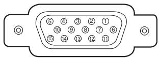
| 1 | Red/Cr/S-C Input | 9 | +5V Power |
| 2 | Green/Y/S-Y Input | 10 | Ground (Vert.sync.) |
| 3 | Blue/Cb/--- Input | 11 | Ground |
| 4 | ---- | 12 | DDC Data |
| 5 | Ground (Horiz.sync.) | 13 | Horiz. sync. Input/Output (Composite H/V sync.) |
| 6 | Ground (Red) | 14 | Vert. sync. |
| 7 | Ground (Green) | 15 | DDC Clock |
| 8 | Ground (Blue) | ||
COMPUTER IN 2/MONITOR OUT (ANALOG)
Terminal: Analog RGB (Mini D-sub 15 pin)
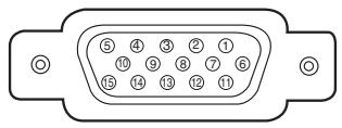
| 1 | Red Input/Output | 9 | ---- |
| 2 | Green Input/Output | 10 | Ground (Vert.sync.) |
| 3 | Blue Input/Output | 11 | ---- |
| 4 | ---- | 12 | ---- |
| 5 | Ground (Horiz.sync.) | 13 | Horiz. sync. Input/Output |
| 6 | Ground (Red) | 14 | Vert. sync. |
| 7 | Ground (Green) | 15 | ---- |
| 8 | Ground (Blue) | ||
CONTROL PORT CONNECTOR (D-sub 9 pin)
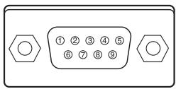
| Serial | |
| 1 | ---- |
| 2 | R X D |
| 3 | T X D |
| 4 | ---- |
| 5 | SG |
| 6 | ---- |
| 7 | RTS |
| 8 | CTS |
| 9 | ---- |
LAN TERMINAL
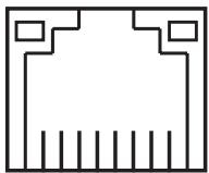
87654321
| 1 | TX + | 5 | ---- |
| 2 | TX - | 6 | RX - |
| 3 | RX + | 7 | ---- |
| 4 | ---- | 8 | ---- |
Dimensions
Unit: mm(inch)

Screw Holes for Ceiling Mount
Screw: M4
Depth: 10.0(0.39)
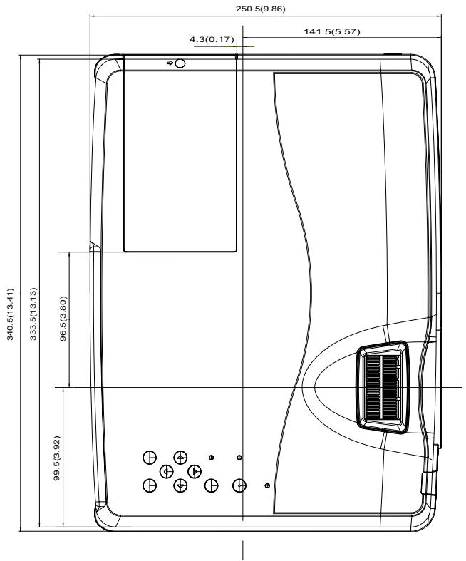
text_image
250.5(9.86) 4.3(0.17) 141.5(5.57) 340.5(13.41) 333.5(13.13) 96.5(3.80) 99.5(3.92)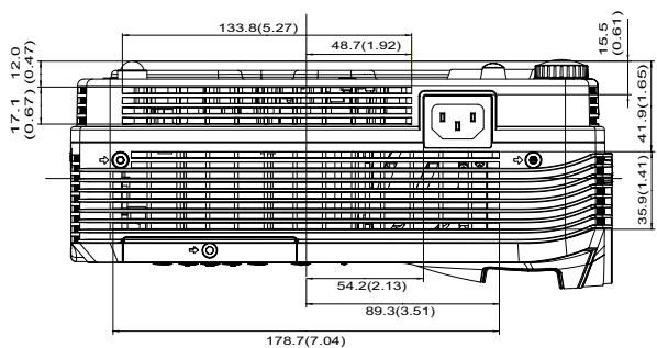
text_image
133.8(5.27) 48.7(1.92) 12.0 (0.47) 17.1 (0.67) 41.9(1.65) 15.5 (0.61) 54.2(2.13) 89.3(3.51) 178.7(7.04)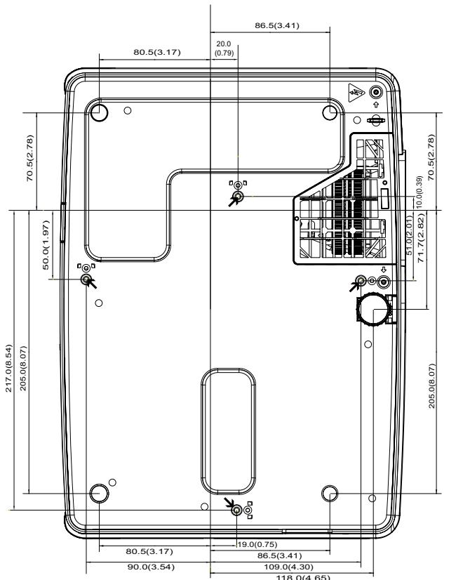
text_image
86.5(3.41) 20.0 (0.79) 80.5(3.17) 70.5(2.78) 70.5(2.78) 50.0(1.97) 10.0(0.39) 51.0(2.01) 71.7(2.82) 217.0(8.54) 205.0(8.07) 205.0(8.07) 80.5(3.17) 19.0(0.75) 86.5(3.41) 90.0(3.54) 109.0(4.30) 118.0(4.65)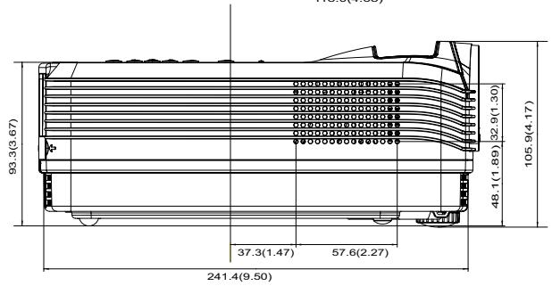
other
| Component | Value | | --------- | ----- | | Total Height | 93.3 (3.67) | | Base Height | 37.3 (1.47) | | Middle Height | 57.6 (2.27) | | Upper Height | 48.1 (1.89) | | Lower Height | 32.9 (1.30) | | Total Width | 105.9 (4.17) | | Total Width (Left) | 241.4 (9.50) |Serial Control Interface
This projector provides a function to control and monitor the projector's operations by using the RS-232C serial port.
Operation
1 Connect a RS-232C serial cross cable to CONTROL PORT on the projector and serial port on the PC. (See p.9)
2 Launch a communication software provided with PC and setup the communication condition as follows:
3 Type the command for controlling the projector and then enter the "Enter" key.
Example
When you want to change the input to COMPUTER 2, Type 'C' '0' '6' 'Enter'.
Functional Execution Command
Format
The command is sent from PC to the projector with the format below;
'C' [Command] 'CR'
Command: two characters (refer to the command table below.
- The projector decodes the command and returns the 'ACK' with the format below; 'ACK' 'CR'
- When the projector cannot decode the command, it returns with format below.
'?' 'CR'
| Command | Function |
| C00 | Turn the projector ON |
| C01 | Turn the projector OFF (immediately OFF) |
| C02 | Turn the projector OFF |
| C05 | Computer 1 |
| C06 | Computer 2 |
| C07 | Video |
| C09 | VOLUME + |
| C0A | VOLUME - |
| C0B | AUDIO MUTE ON |
| C0C | AUDIO MUTE OFF |
| C0D | VIDEO MUTE ON |
| C0E | VIDEO MUTE OFF |
| C0F | Screen Normal size(4 : 3) |
| C10 | Screen Wide size(16 : 9) |
| C11 | Image Standard |
| C12 | Image Real |
| C13 | Image Cinema |
| C14 | Image 1 |
| C15 | Image 2 |
| C16 | Image 3 |
| C17 | Image 4 |
| C18 | Blackboard |
| C19 | Dynamic |
| Baud rate | : 9600 / 19200 bps |
| Parity check | : none |
| Stop bit | : 1 |
| Flow control | : none |
| Data bit | : 8 |
√Note:
- The default of the baud rate is set to 19200 bps. If an error occurs in the communication, change the serial port and the communication speed (baud rate).
- Enter with ASCII 64-byte capital characters and onebyte characters.
| Command | Function |
| C1C | MENU ON |
| C1D | MENU OFF |
| C1E | DISPLAY CLEAR |
| C20 | BRIGHTNESS + |
| C21 | BRIGHTNESS - |
| C27 | IMAGE (Toggle) |
| C28 | Direct on Enable |
| C29 | Direct on Disable |
| C2A | Power Management Ready |
| C2B | Power Management OFF |
| C2E | Power Management Shut down |
| C30 | D.ZOOM + |
| C31 | D.ZOOM - |
| C34 | Computer 1 S-Video |
| C39 | Image Colorboard |
| C3A | POINTER RIGHT |
| C3B | POINTER LEFT |
| C3C | POINTER UP |
| C3D | POINTER DOWN |
| C3F | ENTER |
| C43 | FREEZE ON |
| C44 | FREEZE OFF |
| C50 | Computer 1 Analog RGB |
| C51 | Computer 1 Scart |
| C54 | Computer 1 Component |
| C89 | Auto PC ADJ. |
| C8A | PRESENTATION TIMER |
| C8B | PRESENTATION TIMER (Exit) |
| C8E | KEYSTONE ↑ |
| C8F | KEYSTONE ↓ |
Status Read Command
Format
The command is sent from PC to the projector with the format below;
'CR' [Command] 'CR'
Command: one character (refer to the command table below.
The projector decodes the command and returns the
'Character string' with the format below;
| Command | Function | Projector Return | Projector status |
| CR0 | Status Read | 00 | Power On |
| 80 | Stand-by mode | ||
| 40 | Countdown | ||
| 20 | Cooling down | ||
| 10 | Power Malfunction | ||
| 28 | Cooling down at the temperature anomaly | ||
| 88 | Stand-by mode after Cooling down at the temperature anomaly. | ||
| 24 | Cooling down at Power Management mode | ||
| 04 | Power Management mode after Cooling down | ||
| 21 | Cooling down after the projector is turned off when the lamps are out. | ||
| 81 | Stand-by mode after Cooling down when the lamps are out. | ||
| CR6 | Temperature Read | %1 %2 %3 | %1 = Temperature at Sensor 1 (°C)%2 = Temperature at Sensor 2 (°C)%3 = Temperature at Sensor 3 (°C)(ex.) %1 = 12.3°C, %2 = 23.4°C, %3 = 34.5°C--> The projector displays “12.3 23.4 34.5”( For each sensor, two digit and the tenth place numbers are displayed with a space between each temperature.) |
| ? | Communication failure |
The tables on pages 75 and 76 show the typical command lists for controlling the projector. Please consult your local dealer for further information of other commands.
Customer Support
For technical support or product service, see the table below or contact your reseller.
Note : You will need the product serial number.
| Country/Region | Website | T = TelephoneF = FAX | |
| Australia/New Zealand | www.viewsonic.com.au | AUS= 1800 880 818NZ= 0800 008 822 | service@au.viewsonic.com |
| Canada | www.viewsonic.com | T (Toll-Free)= 1-866-463-4775T (Toll)= 1-424-233-2533F= 1-909-468-3757 | service.ca@viewsonic.com |
| Europe | www.viewsoniceurope.com | www.viewsoniceurope.com/uk/support/call-desk/ | |
| Hong Kong | www.hk.viewsonic.com | T= 852 3102 2900 | service@hk.viewsonic.com |
| India | www.in.viewsonic.com | T= 1800 11 9999 | service@in.viewsonic.com |
| Ireland (Eire) | www.viewsoniceurope.com/uk/ | www.viewsoniceurope.com/uk/support/call-desk/ | service_ie@viewsoniceurope.com |
| Korea | www.kr.viewsonic.com | T= 080 333 2131 | service@kr.viewsonic.com |
| Latin America(Argentina) | www.viewsonic.com/la/ | T= 0800-4441185 | soporte@viewsonic.com |
| Latin America (Chile) | www.viewsonic.com/la/ | T= 1230-020-7975 | soporte@viewsonic.com |
| Latin America(Columbia) | www.viewsonic.com/la/ | T= 01800-9-157235 | soporte@viewsonic.com |
| Latin America (Mexico) | www.viewsonic.com/la/ | T= 001-8882328722 | soporte@viewsonic.com |
| Renta y Datos, 29 SUR 721, COL. LA PAZ, 72160 PUEBLA, PUE. Tel: 01.222.891.55.77 CON 10 LINEASElectroser, Av Reforma No. 403Gx39 y 41, 97000 Mérida, Yucatán. Tel: 01.999.925.19.16Other places please refer to http://www.viewsonic.com/la/soporte/index.htm#Mexico | |||
| Latin America (Peru) | www.viewsonic.com/la/ | T= 0800-54565 | soporte@viewsonic.com |
| Macau | www.hk.viewsonic.com | T= 853 2870 0303 | service@hk.viewsonic.com |
| Middle East | ap.viewsonic.com/me/ | Contact your reseller | service@ap.viewsonic.com |
| Puerto Rico & Virgin Islands | www.viewsonic.com | T= 1-800-688-6688 (English)T= 1-866-379-1304 (Spanish)F= 1-909-468-3757 | service.us@viewsonic.comsoporte@viewsonic.com |
| Singapore/Malaysia/Thailand | www.ap.viewsonic.com | T= 65 6461 6044 | service@sg.viewsonic.com |
| South Africa | ap.viewsonic.com/za/ | Contact your reseller | service@ap.viewsonic.com |
| United Kingdom | www.viewsoniceurope.com/uk/ | www.viewsoniceurope.com/uk/support/call-desk/ | service_gb@viewsoniceurope.com |
| United States | www.viewsonic.com | T (Toll-Free)= 1-800-688-6688T (Toll)= 1-424-233-2530F= 1-909-468-3757 | service.us@viewsonic.com |
Limited Warranty
VIEWSONIC® PROJECTOR
What the warranty covers:
ViewSonic warrants its products to be free from defects in material and workmanship, under normal use, during the warranty period. If a product proves to be defective in material or workmanship during the warranty period, ViewSonic will, at its sole option, repair or replace the product with a like product. Replacement product or parts may include remanufactured or refurbished parts or components.
Limited Three (3) year General Warranty
Subject to the more limited one (1) year warranty set out below, North and South America: Three (3) years warranty for all parts excluding the lamp, three (3) years for labor, and one (1) year for the original lamp from the date of the first consumer purchase; Europe except Poland: Three (3) years warranty for all parts excluding the lamp, three (3) years for labor, and ninety (90) days for the original lamp from the date of the first consumer purchase; Poland: Two (2) years warranty for all parts excluding the lamp, two (2) years for labor, and ninety (90) days for the original lamp from the date of the first consumer purchase.
Limited One (1) year Heavy Usage Warranty:
Under heavy usage settings, where a projector's use includes more than fourteen (14) hours average daily usage, North and South America: One (1) year warranty for all parts excluding the lamp, one (1) year for labor, and ninety (90) days for the original lamp from the date of the first consumer purchase; Europe: One (1) year warranty for all parts excluding the lamp, one (1) year for labor, and ninety (90) days for the original lamp from the date of the first consumer purchase.
Other regions or countries: Please check with your local dealer or local ViewSonic office for the warranty information.
Lamp warranty subject to terms and conditions, verification and approval. Applies to manufacturer's installed lamp only. All accessory lamps purchased separately are warranted for 90 days.
Who the warranty protects:
This warranty is valid only for the first consumer purchaser.
What the warranty does not cover:
- Any product on which the serial number has been defaced, modified or removed.
- Damage, deterioration, failure, or malfunction resulting from:
a. Accident, abuse, misuse, neglect, fire, water, lightning, or other acts of nature, improper maintenance, unauthorized product modification, or failure to follow instructions supplied with the product.
b. Operation outside of product specifications.
c. Operation of the product for other than the normal intended use or not under normal conditions.
d. Repair or attempted repair by anyone not authorized by ViewSonic.
e. Any damage of the product due to shipment.
f. Removal or installation of the product.
g. Causes external to the product, such as electric power fluctuations or failure.
h. Use of supplies or parts not meeting ViewSonic's specifications.
i. Normal wear and tear.
j. Any other cause which does not relate to a product defect.
- Removal, installation, and set-up service charges.
How to get service:
- For information about receiving service under warranty, contact ViewSonic Customer Support (please refer to "Customer Support" page). You will need to provide your product's serial number.
- To obtain warranted service, you will be required to provide (a) the original dated sales slip, (b) your name, (c) your address, (d) a description of the problem, and (e) the serial number of the product.
- Take or ship the product freight prepaid in the original container to an authorized ViewSonic service center or ViewSonic.
- For additional information or the name of the nearest ViewSonic service center, contact ViewSonic.
Limitation of implied warranties:
There are no warranties, express or implied, which extend beyond the description contained herein including the implied warranty of merchantability and fitness for a particular purpose.
Exclusion of damages:
ViewSonic's liability is limited to the cost of repair or replacement of the product. ViewSonic shall not be liable for:
- Damage to other property caused by any defects in the product, damages based upon inconvenience, loss of use of the product, loss of time, loss of profits, loss of business opportunity, loss of goodwill, interference with business relationships, or other commercial loss, even if advised of the possibility of such damages.
- Any other damages, whether incidental, consequential or otherwise.
- Any claim against the customer by any other party.
Effect of state law:
This warranty gives you specific legal rights, and you may also have other rights which vary from state to state. Some states do not allow limitations on implied warranties and/or do not allow the exclusion of incidental or consequential damages, so the above limitations and exclusions may not apply to you.
Sales outside the U.S.A. and Canada:
For warranty information and service on ViewSonic products sold outside of the U.S.A. and Canada, contact ViewSonic or your local ViewSonic dealer.
The warranty period for this product in mainland China (Hong Kong, Macao and Taiwan Excluded) is subject to the terms and conditions of the Maintenance Guarantee Card.
For users in Europe and Russia, full details of warranty provided can be found in www.viewsoniceurope.com under Support/Warranty Information.
4.3: Projector Warranty
PRJ_LW01 Rev. 1h 06-25-07
Mexico Limited Warranty
VIEWSONIC® PROJECTOR
What the warranty covers:
ViewSonic warrants its products to be free from defects in material and workmanship, under normal use, during the warranty period. If a product proves to be defective in material or workmanship during the warranty period, ViewSonic will, at its sole option, repair or replace the product with a like product. Replacement product or parts may include remanufactured or refurbished parts or components & accessories.
How long the warranty is effective:
3 years for all parts excluding the lamp, 3 years for labor, 1 year for the original lamp from the date of the first consumer purchase.
Lamp warranty subject to terms and conditions, verification and approval. Applies to manufacturer's installed lamp only. All accessory lamps purchased separately are warranted for 90 days.
Who the warranty protects:
This warranty is valid only for the first consumer purchaser.
What the warranty does not cover:
- Any product on which the serial number has been defaced, modified or removed.
- Damage, deterioration or malfunction resulting from:
a. Accident, misuse, neglect, fire, water, lightning, or other acts of nature, unauthorized product modification, unauthorized attempted repair, or failure to follow instructions supplied with the product.
b. Any damage of the product due to shipment.
c. Causes external to the product, such as electrical power fluctuations or failure.
d. Use of supplies or parts not meeting ViewSonic's specifications.
e.Normal wear and tear.
f. Any other cause which does not relate to a product defect.
- Any product exhibiting a condition commonly known as “image burn-in” which results when a static image is displayed on the product for an extended period of time.
- Removal, installation, insurance, and set-up service charges.
How to get service:
For information about receiving service under warranty, contact ViewSonic Customer Support (Please refer to the attached Customer Support page). You will need to provide your product's serial number, so please record the product information in the space provided below on your purchase for your future use. Please retain your receipt of proof of purchase to support your warranty claim.
For Your Records
Product Name: ____
Document Number: ____
Purchase Date: ____
Model Number: ____
Serial Number: ____
Extended Warranty Purchase? ____ (Y/N)
If so, what date does warranty expire? ____
- To obtain warranty service, you will be required to provide (a) the original dated sales slip, (b) your name, (c) your address, (d) a description of the problem, and (e) the serial number of the product.
- Take or ship the product in the original container packaging to an authorized ViewSonic service center.
- Round trip transportation costs for in-warranty products will be paid by ViewSonic.
Limitation of implied warranties:
There are no warranties, express or implied, which extend beyond the description contained herein including the implied warranty of merchantability and fitness for a particular purpose.
Exclusion of damages:
ViewSonic's liability is limited to the cost of repair or replacement of the product. ViewSonic shall not be liable for:
- Damage to other property caused by any defects in the product, damages based upon inconvenience, loss of use of the product, loss of time, loss of profits, loss of business opportunity, loss of goodwill, interference with business relationships, or other commercial loss, even if advised of the possibility of such damages.
- Any other damages, whether incidental, consequential or otherwise.
- Any claim against the customer by any other party.
- Repair or attempted repair by anyone not authorized by ViewSonic.
| Contact Information for Sales & Authorized Service (Centro Autorizado de Servicio) within Mexico: | |
| Name, address, of manufacturer and importers:México, Av. de la Palma #8 Piso 2 Despacho 203, Corporativo Interpalmas,Col. San Fernando Huixquilucan, Estado de MéxicoTel: (55) 3605-1099 http://www.viewsonic.com/la/soporte/index.htm | |
| NÚMERO GRATIS DE ASISTENCIA TÉCNICA PARA TODO MÉXICO: 001.866.823.2004 | |
| Hermosillo:Distribuciones y Servicios Computacionales SA de CV.Calle Juarez 284 local 2Col. Bugambilas C.P: 83140Tel: 01-66-22-14-9005E-Mail: disc2@hmo.megared.net.mx | Villahermosa:Compumantenimietnos Garantizados, S.A. de C.V.AV. GREGORIO MENDEZ #1504COL, FLORIDA C.P. 86040Tel: 01 (993) 3 52 00 47 / 3522074 / 3 52 20 09E-Mail: compumantenimientos@prodigy.net.mx |
| Puebla, Pue. (Matriz):RENTA Y DATOS, S.A. DE C.V. Domicilio:29 SUR 721 COL. LA PAZ72160 PUEBLA, PUE.Tel: 01(52).222.891.55.77 CON 10 LINEASE-Mail: datos@puebla.megared.net.mx | Veracruz, Ver.:CONEXION Y DESARROLLO, S.A DE C.V. Av. Americas # 419ENTRE PINZÓN Y ALVARADOFracc. Reforma C.P. 91919Tel: 01-22-91-00-31-67E-Mail: gacosta@qplus.com.mx |
| ChihuahuaSoluciones Globales en ComputaciónC. Magisterio # 3321 Col. MagisterialChihuahua, Chih.Tel: 4136954E-Mail: Cefeo@soluglobales.com | CuernavacaCompusupport de Cuernavaca SA de CVFrancisco Leyva # 178 Col. Miguel HidalgoC.P. 62040, Cuernavaca MorelosTel: 01 777 3180579 / 01 777 3124014E-Mail: aquevedo@compusupportcva.com |
| Distrito Federal:QPLUS, S.A. de C.V.Av. Coyoacán 931Col. Del Valle 03100, México, D.F.Tel: 01(52)55-50-00-27-35E-Mail : gacosta@qplus.com.mx | Guadalajara, Jal.:SERVICRECE, S.A. de C.V.Av. Niños Héroes # 2281Col. Arcos Sur, Sector Juárez44170, Guadalajara, JaliscoTel: 01(52)33-36-15-15-43E-Mail: mmiranda@servicrece.com |
| Guerrero AcapulcoGS Computación (Grupo Sesicomp)Progreso #6-A, Colo Centro39300 Acapulco, GuerreroTel: 744-48-32627 | Monterrey:Global Product ServicesMar Caribe # 1987, Esquina con Golfo PérsicoFracc. Bernardo Reyes, CP 64280Monterrey N.L. MéxicoTel: 8129-5103E-Mail: aydeem@gps1.com.mx |
| MERIDA:ELECTROSERAv Reforma No. 403Gx39 y 41Mérida, Yucatán, México CP97000Tel: (52) 999-925-1916E-Mail: rrrb@sureste.com | Oaxaca, Oax.:CENTRO DE DISTRIBUCION YSERVICIO, S.A. de C.V.Murguía # 708 P.A., Col. Centro, 68000, OaxacaTel: 01(52)95-15-15-22-22Fax: 01(52)95-15-13-67-00E-Mail. gpotai2001@hotmail.com |
| Tijuana:STDAv Ferrocarril Sonora #3780 L-CCol 20 de NoviembreTijuana, Mexico | FOR USA SUPPORT:ViewSonic Corporation381 Brea Canyon Road, Walnut, CA. 91789 USATel: 800-688-6688 (English); 866-323-8056 (Spanish);Fax: 1-800-685-7276E-Mail: http://www.viewsonic.com |
4.3: ViewSonic Mexico Limited Warranty
PRJ_LW03 Rev. 1A 06-25-07
Network Set-up and Operation

CAUTION IN USING THE PROJECTOR VIA NETWORKS
- When you find a problem with the projector, remove the power cable immediately and inspect the unit. Using the projector with failure may cause fire or other accidents.
- If you remotely use the projector via networks, carry out a safety check regularly and take particular care to its environment. Incorrect installation may cause fire or other accidents.

CAUTION IN USING NETWORK FUNCTION
- We assume no responsibility for the loss or damage of data, or damage of the computer caused by using this projector. Making back-up copies of valuable data in your computer is recommended.
Safety instructions....3
Table of contents 4
Chapter 1 Preparation ....5
Features......6
Required operating environment for computers....7
Network specifications of the projector 7
Flow of installation....9
Notice about installing Software CD-ROM....9
Chapter 2 Setup Procedures....11
Connecting to the LAN line....12
Network configuration....12
Network PIN code 14
Network information....14
Network factory default....15
Wired LAN factory default settings....16
Chapter 3 Basic Setting and Operation....17
Login the setting page of the projector....18
[1] Enter the IP address.... 18
[2] Login 18
[3] Display of main setting page....19
How to use the setting page 20
Initial setting....22
Network PIN code setting 23
PJLink and password setting....23
Network configuration....24
E-mail setting 25
Examples: Type and contents of alert mail 28
SNMP setting....29
Chapter 4 Controlling the Projector .... 31
Power control and status check....32
Control....34
Input 34
System....35
Sound 36
Image adjustment....37
PC adjustment....38
Setting up the projector 39
Screen setting 39
Setting 1....40
Setting 2....40
Setting 3....41
Information....42
Chapter 5 Appendix ......43
Examples of connection....44
Use of telnet....46
Web browser setting....48
Examples: OS/Browsers 49
Q&A 53
Chapter 1
Preparation
Describes features and operating environment of this projector.
1
Features
Web Management function (+p.31)
With this function, you can monitor projector functions such as power status, lamp status, input mode, signal condition, lamp-use time, etc. through the network by using the web browser installed on your computer.

flowchart
graph TD
    PC1["PC1"] --> PC3["PC3"]
    PC2["PC2"] --> PC4["PC4"]
    PC3 --> PC5["PC5"]
    PC4 --> PC5
    PC5 --> PC6["PC6"]
    PC5 --> PJ2["PJ2"]
    PJ2 --> PJ1["PJ1"]
    PJ1 --> PC6
    style PC5 stroke:#000,stroke-width:2px
    note right of PC5: "Turn ON PJ2"
E-Mail Alert function (+p.25)
The projector sends messages to the registered e-mail addresses when a lamp abnormality or power failure occurs with the projector. This message describes how to solve the cause of the problems. You can take efficient action for quick recovery.
flowchart
graph TD
    PC1["PC1"] --> R1["Router"]
    PC2["PC2"] --> R2["Router"]
    PC3["PC3"] --> R3["Router"]
    PC4["PC4"] --> R4["Router"]
    R1 --> PC5["PC5"]
    R2 --> PC5
    R3 --> PC5
    R4 --> PC5
    PC5 -->|You've got Mail.| R5["Router"]
    R5 --> PJ1["PC1"]
    R5 --> PJ2["PC2"]
    R5 --> PJ3["PC3"]
    style R1 fill:#f9f,stroke:#333
    style R2 fill:#f9f,stroke:#333
    style R3 fill:#f9f,stroke:#333
    style R4 fill:#f9f,stroke:#333
    style R5 fill:#ccf,stroke:#333
    style PJ1 fill:#dfd,stroke:#333
    style PJ2 fill:#dfd,stroke:#333
    style PJ3 fill:#dfd,stroke:#333
SNMP Agent function (+p.29)
To send the information of the projector to the SNMP manager. Enables you to manage the projector condition with the supplied SNMP manager software.
SNMP Manager function
A function to manage the condition of projectors in the network by using the SNMP protocol. The managing computer needs to provide an SNMP managing software. Refer to the owner's manual of the "PJ Network Manager" supplied separately for further details.
flowchart
graph TD
    subgraph Switches
        PJ1["BJ1"] -->|Trap| PC6["PC6"]
        PJ2["BJ2"] -->|Trap| PC6
        PJ3["BJ3"] -->|Trap| PC6
        PJ4["BJ4"] -->|Trap| PC6
        PC6 -->|Trap| SNMP["SNMP Manager"]
        SNMP -->|Yes/No| PC5["PC5"]
        SNMP -->|Yes/No| PC5
        SNMP -->|Yes/No| PC4["PC4"]
    end
    subgraph Switches
        PJ1 -->|Bar Chart with Green/Red/Gray Green/Blue Grids| Switcher["PJ1"]
        PJ2 -->|Bar Chart with Green/Red/Blue Grids| Switcher
        PJ3 -->|Bar Chart with Green/Red/Blue Grids| Switcher
        PJ4 -->|Bar Chart with Green/Red/Blue Grids| Switcher
    end
    Switcher -->|Yes/No| SNMP
    Switcher -->|Yes/No| SNMP
    subgraph Switches
        Switcher -->|Yes/No| SNMP
    end
Required operating environment for computers
When operating the projector via networks, computers should meet the operating environment below.
| Operating System | Windows 2000, Windows XP (32bit version), Windows Vista (32bit version), Windows 7 (32bit version) Mac OS X v 10.4 or 10.5 | |
| Computer environment | Recommended CPU | Windows: Pentium III 900MHz or more Macintosh : 800 MHz PowerPC G4 or faster, or 1.8 GHz Intel Core Processor or faster |
| Memory | Windows : 64MB (Minimum)/ 128MB or more (Recommended) 128MB or more for Windows XP 1GB or more for Windows Vista or Windows 7 Macintosh : 256MB or more (512MB is recommended) | |
| Free disk space | 100MB or more | |
| Drive equipment | CD-ROM drive | |
| Display settings | Support one of following resolutions; VGA (640 x 480), SVGA(800 x 600), XGA(1,024 x 768) Number of colors: Either of 16 bit (65,536 color 24/32 bit (16.77 million colors)) | |
| Network card | The computer must provide a 10Base-T or 100Base-TX network card. | |
| Web Browser* | Internet Explorer version 6.0, 7.0 or 8.0 Netscape Navigator version 7.1 or 9.0 Safari 3.1 * Used to control and set up the projector. The layout of pages in the browser may slightly differ from each type of application or operating system you use. | |
| Recommended Internet Mailer* | - Microsoft Outlook - Microsoft Outlook Express - Netscape Mail * Required the internet e-mail application software to receive an e-mail alert sent from this projector. If you do not use the function E-mail Alert, this application is not required. | |
Network specifications of the projector
LAN Terminal
| Data communication standards | 10Base-T (10Mbps) / 100Base-TX compatible |
| Protocol | TCP/IP |
Cabling Between the Projector and a Hub or computer ^*1
Use an appropriate cable when connecting the projector and a hub or computer.
| Connection | Ethernet cable type | Max. cable length |
| Projector - Hub | STP straight-through category 5*2cable | 100m (328feet) |
| Projector - Computer | STP crossover category 5*2cable | 100m (328feet) |
*1 There may be other limitations depending on your network environment or LAN specification. Please consult your network administrator for further details.
*2 Cable category indicates cable quality.
Notice
Expression/Abbreviation
The OS of the computer and the Web browser described in this manual are Windows XP Professional and Internet Explorer 6.0. In case of another OS or Web browser, some instruction procedures may differ from the actual operation depending on your computer environment.
Use of this manual
This manual does not provide the detailed description of basic operation and functions for computer, web browser, projector and network. For instructions about each piece of equipment or application software, please refer to the respective manual.
Trademarks
Ethernet is a registered trademark of Xerox Corporation. Microsoft, Windows, Windows 2000, Windows XP, Windows Vista and Windows 7 are registered trademarks of Microsoft Corporation in the United States and other countries. Internet Explorer is a registered trademark of Microsoft Corporation. Netscape Navigator and Netscape Communicator are trademarks or registered trademarks of Netscape Communications Corporation. JavaScript is a registered trademark of Sun Microsystems, Inc.
Macintosh is a registered trademark of Apple, Inc. in the USA and other countries. PowerPC is a registered trademark of IBM Corporation. Intel Core is a registered trademark of Intel Corporation in the USA and other countries.
Other product or brand names in this manual are registered trademarks or trademarks of their respective owners.
* Unauthorized use of a part or whole of the contents in this manual is prohibited.
* The contents of this manual are subject to change without notice.
Flow of installation
To use the projector via the networks, follow the setup procedures below.
STEP 1 Connect the LAN and set the configuration.

Decide depending on the LAN environment.
* "2. Setup Procedures" (pp.11–16).
Detailed LAN configurations need to be done with a browser later.
First, complete the Wired LAN connection between computers and projectors, then start browser configurations.
* "3. Basic setting and operation" (pp.17–30).
STEP 2 Network Configuration has completed.

Follow each chapter to operate the projector.
■ Operate and manage the projector * "4. Controlling the projector" (pp.31-42)
* "Power Control and status check" (p.32)
* "Control" (p.34)
* "PC adjustment" (p.38)
* "Setting up the projector" (p.39)
*□□□□□ "Projector information" (p.42)
STEP 3 Install the Software on computers.
Install the software recorded in CD-ROM on each computer which will be operated. Refer to the owner's manual of PJ Network Manager.
Notice about installing Software CD-ROM
It is available for controlling and setting of the projector by using the web browser without installing any software. So it is not required to install the software into your computer.
For PJ Network Manager function, it is required to install the software. Please see the owner's manual of "PJ Network Manager Function".
Chapter 2
Setup Procedures
Describes how to configure the network.
2
Setting procedures and contents differ depending on the LAN installation location. When installing, consult your system administrator to set up the LAN appropriately.
Connecting to the LAN line
Connect the LAN cable to the LAN connection terminal of the projector.
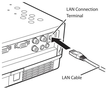
text_image
LAN Connection Terminal LAN Cable* Please use a shielded LAN cable.
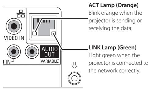
text_image
ACT Lamp (Orange) Blink orange when the projector is sending or receiving the data. LINK Lamp (Green) LIGHT GREEN WHEN THE PROJECTOR IS CONNECTED TO THE NETWORK CORRECTLY.Network configuration
Set the Wired LAN network through the projector menu. Detailed network settings will be made with browser. Refer to "3. Basic setting and operation" (p.17-30). First, complete the settings described in this chapter before performing steps in "3. Basic setting and operation."
Setting Procedure
- Select "LAN mode select" in the Network menu, and press Point 8 or SELECT button.
- Select similar LAN environment among LAN1, LAN2 and LAN3 with the Point ed buttons, and press SELECT button. Then the Menu will disappear, the "Please wait..." message will appear, and switching operation will start. Switching will take a while and the projector's LINK/ACT Lamp will be on or blink, and after completing the operation, the "Please wait..." message will disappear.
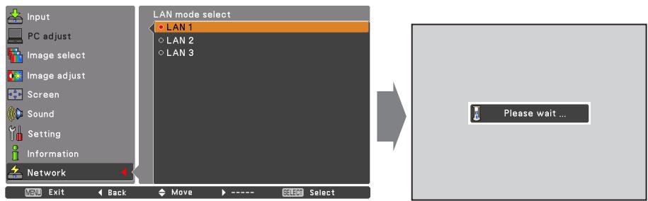
text_image
Input PC adjust Image select Image adjust Screen Sound Setting Information Network LAN mode select • LAN 1 • LAN 2 • LAN 3 Please wait ...- Select "Network setting" in the Network menu and press SELECT button, and then the LAN setting screen will appear and selected LAN settings will be displayed. Adjust each item to the setting environment. Consult your system administrator about the detailed settings.
Press SELECT button in a row where you want to adjust, and adjust the figures with the Point ed buttons and move among the items with the Point 7 8 buttons, and then press SELECT button to fix. Move to the next row with the Point ed buttons to adjust.
- After completing all the settings, select "Set" and press SELECT button. Now, all procedures have been done. To cancel the adjusted settings, select "Cancel" and press SELECT button.
You can confirm the LAN settings you have made from "Network information" (p.14). In such cases that the LAN cannot be connected, see this screen.
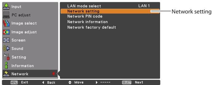
text_image
Input PC adjust Image select Image adjust Screen Sound Setting Information Network LAN mode select Network setting Network PIN code Network information Network factory default LAN 1 Network setting VOUT Exit Back Move ---- SELECT NextDHCP: On
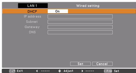
text_image
LAN 1 Wired setting DHCP On IP address Subnet Gateway DNS Set Cancel V5U Exit <---- Adjust > ---- Setup SetDHCP: Off
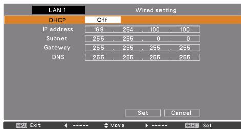
text_image
LAN 1 Wired setting DHCP Off IP address 169 . 254 . 100 . 100 Subnet 255 . 255 . 0 . 0 Gateway 255 . 255 . 255 . 255 DNS 255 . 255 . 255 . 255 Set Cancel VSU Exit ←----Move►----SET SET* The numerical value is a setting example.
Item Description
DHCP......Sets DHCP function On or Off. When you setup the network setting manually, select "Off". When it is set On, IP address, Subnet, Gateway and DNS are automatically set according to your network environment *1.
IP address ......Sets IP address of the projector
Subnet ....Sets Subnet mask according to your network environment.
Gateway ^*2 ......Sets IP address of the default gateway (Router)
DNS ^*3 ....Sets IP address of the DNS server.
Network PIN code
The Network PIN code is to restrict the access to the projector through the network.
After setting the Network PIN code, you need to enter it to operate the projector via the networks.
- Select "Network PIN code" in the Network menu, and press SELECT button.
The Network PIN code screen will appear.
- Set the Network PIN code.
Set the figures with the Point ed buttons and move to the next items with the Point 7 8 buttons. Select "Set" and press SELECT button to set. To cancel the preset Network PIN code, select "Cancel". When you do not want to set the Network PIN code, set "0000".
It is recommended to set the Network PIN code if you use the projector via the networks. The Network PIN code can be set also through the networks. See "3. Basic setting and operation" "Initial setting" "Network PIN code setting"(p.23).
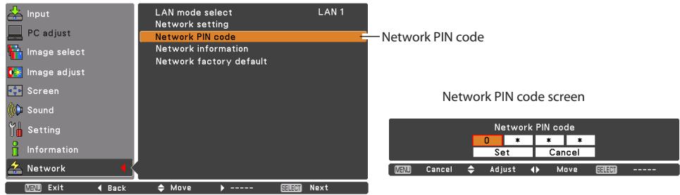
text_image
Input PC adjust Image select Image adjust Screen Sound Setting Information Network LAN mode select LAN 1 Network setting Network PIN code Network information Network factory default Network PIN code Network PIN code screen 0 * * Set Cancel VENU Cancel Adjust Move SELECT ---- VENU Exit Back Move ---- Select NextNetwork information
Select "Network information" in the Network menu and press Point 8 or SELECT button to show LAN setting environment of the currently selected projector. (The description below is an example and different from what will be shown.)
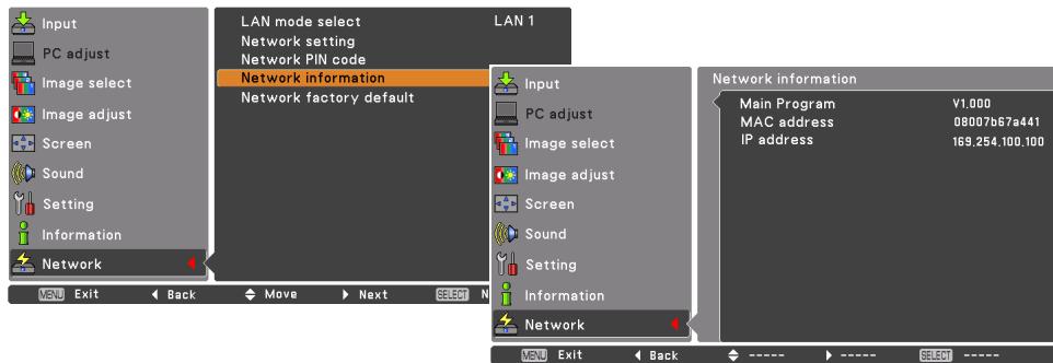
text_image
Input PC adjust Image select Image adjust Screen Sound Setting Information Network LAN mode select Network setting Network PIN code Network information Network factory default LAN 1 Input PC adjust Image select Image adjust Screen Sound Setting Information Network Network information Main Program V1.000 MAC address 08007b67a441 IP address 169,254,100,100 VENU Exit Back Move Next SELECT N VENU Exit Back ---->---->---->---->* The numerical value is a setting example.
Network factory default
- Select "Network factory default" in the Network menu and press SELECT button.
- A confirmation box appears and select "Yes" and then press SELECT button.
- Another confirmation box appears and select "Yes" and then press SELECT button.
- All the wired LAN settings will go back to the factory default settings. For details, refer to "Wired LAN factory default settings" (p.16).
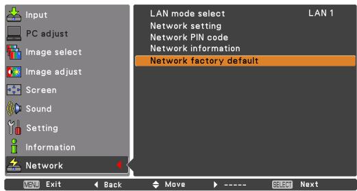
text_image
Input PC adjust Image select Image adjust Screen Sound Setting Information Network LAN mode select LAN 1 Network setting Network PIN code Network information Network factory default VND Exit Back Move ---- SEOR Next
flowchart
graph TD
    A["Return to Network factory default ?"] --> B{Yes}
    A --> C{No}
    B --> D["Exit"]
    C --> E["Move"]
    E --> F["Select"]
    G["Return to Network factory default ?"] --> H{Yes}
    G --> I{No}
    J["OK ?"] --> K{Yes}
    J --> L{No}
    M["Exit"] --> N["Move"]
    N --> O["Select"]
Wired LAN factory default settings
| Parameter | SELECTED LAN | ||
| LAN 1 | LAN 2 | LAN 3 | |
| DHCP | OFF | ON | OFF |
| IP ADDRESS | 169.254.100.100 | 192.168.100.100 | 192.168.100.100 |
| SUBNET MASK | 255.255.0.0 | 255.255.255.0 | 255.255.255.0 |
| GATEWAY ADDRESS | 255.255.255.255 | 255.255.255.255 | 255.255.255.255 |
| DNS ADDRESS | 255.255.255.255 | 255.255.255.255 | 255.255.255.255 |
Chapter 3
Basic Setting and Operation
Describes basic operations and settings for controlling the projector by using the web browser. It is required that computer and projector is connected to the network and the network address is properly configured.
3
Login the setting page of the projector
[1] Enter the IP address
Launch the web browser installed in your computer, enter the IP address into the "Address" on the browser and then press "Enter" key.
Enter the address that you configured in item "Network configuration" (p.12).
![VIEWSONIC PJL6223 - [1] Enter the IP address - 1](/content/2025/01/170006/images/7243fe830c1ce14568a3823514e9927ca874bc9c1616b8545cb1ff5602f894bd.jpg)
text_image
Network - Microsoft Internet Explorer File Edit View Favorites Tools Help Back Search Address http://192.168.1.201/![VIEWSONIC PJL6223 - [1] Enter the IP address - 2](/content/2025/01/170006/images/01bd5695271959cdac89438b88da45550de12f08fdc570d4ebd9e8a0b5e614d6.jpg)
text_image
http://192.168.1.201/ Amazon.co.jp Yahoo! JAPAN News (147)* The numerical value is a setting example.
[2] Login
If the setting page has set the password, the authentication window will appear. In this case type "user" onto the User Name text area and the login Network PIN code onto the Password text area and then click OK (Log in) button.
* The entering User Name must be "user" and it can not be changed.
[Note]
When accessing the projector for the first time or the Network PIN code "0000" is set, the auto-login will be performed and the next main setting page is displayed.
![VIEWSONIC PJL6223 - [Note] - 1](/content/2025/01/170006/images/309e9503974a698a1d2bd41d34071e11fca178430367eeda68a14834ceea9163.jpg)
text_image
Connect to 192.168.1.201 id = user User name: user Password: ••••• Remember my password OK Cancel![VIEWSONIC PJL6223 - [Note] - 2](/content/2025/01/170006/images/7412e18b0f930974b40e9f79d45c69ac20233f3636c803657b73bd9e4d2b4973.jpg)
text_image
To view this page, you need to log in to area "id = user" on 192.168.1.201. Your password will be sent in the clear. Name: user Password: ****** Remember this password in my keychain Cancel Log In[3] Display of main setting page
The following main setting page will be displayed according to your display mode selection. Perform various kinds of settings through this page. Click on the menus to display the control and setting pages.
Main setting page in the display
![VIEWSONIC PJL6223 - [3] Display of main setting page - 1](/content/2025/01/170006/images/0246d074ca17d5a71e372cf13c18e830fa4e766be10f4f59d9ce63cfde009986.jpg)
text_image
Control Input / System / Sound / Image adi Contrast 32 Set + Brightness 32 Set + Color 32 Set + Tint 32 Set + Color temp. Mid Set White balance Red 32 Set + Green 32 Set + Blue 32 Set + Sharpness 8 Set + Gamma 8 Set + Noise reduction L1 Set Progressive L1 Set Reset Reset Store Image Store Load image mode Standard Load Sub menu tab Switches the sub menu tab. Main menu For selection of control and setting items of the projector. Setting page Displays the control and setting items according to the selected menu.How to use the setting page
To control and set up the projector, use the setting menus on the web browser. Describes the basic operation and procedures commonly used on this manual.
Example of the setting page
The setting menu appears when clicking the sub menu tab.
* Each item has a valid setting range respectively.
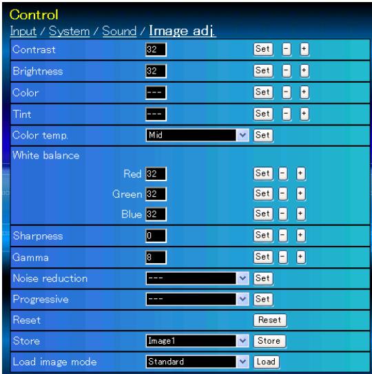
text_image
Control Input / System / Sound / Image adj. Contrast 32 Set - + Brightness 32 Set - + Color --- Set - + Tint --- Set - + Color temp Mid Set White balance Red 32 Set - + Green 32 Set - + Blue 32 Set - + Sharpness 0 Set - + Gamma 8 Set - + Noise reduction --- Set Progressive --- Set Reset Reset Store Image1 Store Load image mode Standard LoadTypes of setting
Text box setting
Enter a number or text and then click Set button.
or
Change a value with - or + button.
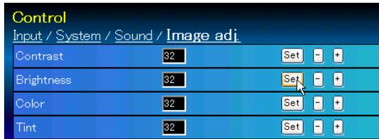
text_image
Control Input / System / Sound / Image adj. Contrast 32 Set - + Brightness 32 Set - + Color 32 Set - + Tint 32 Set - +Pull-down menu setting
Select an item with pull-down menu button and then click Set button.
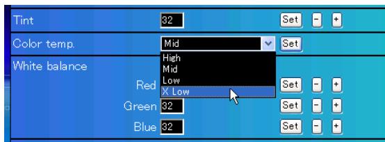
text_image
Tint 32 Color temp. Mid Set White balance High Mid Low X Low Red Green 32 Set - + Blue 32 Set - +* The value in the text box indicates current value.
* Each item has a valid setting range. The setting value exceeding this becomes invalid. Some control items can not be used depending on the selecting input mode or functions of the projector you use. In this case, the values of those items are indicated with "--".
Radio button setting
Select an item by selecting a radio button.

text_image
Control Input / System / Sound / Image adj. Computer1 RGB Computer2 RGB Video SetCheck box setting
Select items by ticking on check boxes.
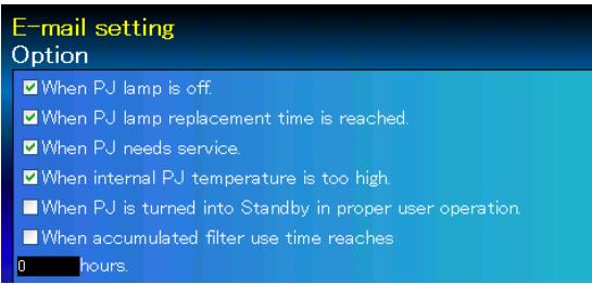
text_image
E-mail setting Option ✓ When PJ lamp is off. ✓ When PJ lamp replacement time is reached. ✓ When PJ needs service. ✓ When internal PJ temperature is too high. ■ When PJ is turned into Standby in proper user operation. ■ When accumulated filter use time reaches 0 hours.
natural_image
Blue glossy circular icon with a camera and gear symbol (no text or numbers)Initial setting
After installing the projector, perform the following basic initial setting. Click Initial Setting on the main menu to display the initial setting page.
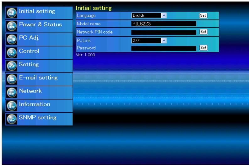
text_image
Initial setting Language English Set Model name PJL6223 Network PIN code Set PJLink OFF Set Password Set Ver. 1.000 Initial setting Power & Status PC Adj. Control Setting E-mail setting Network Information SNMP settingItem Description
Language......Switches display language on the setting page. (Japanese, English)
Model name .....Indicates the model name of the projector
Network PIN code .....Sets the Network PIN code to login the setting page (+p.23)
PJLink....Switches PJLink password authentication. (ON, OFF) (+p.23)
Password......Password for PJLink function (+p.23)
Network PIN code setting
This is to set the Network PIN code to restrict the access from an unauthorized person through the network.
Enter a 4-digit number as the Network PIN code onto the text box and click Set button.
The projector begins restarting and it takes about 10 seconds. Close (Quit) the web
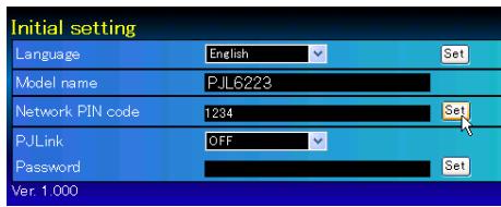
text_image
Initial setting Language English Set Model name PJL6223 Network PIN code 1234 Set PJLink OFF Set Password Set Ver 1.000browser and access to the login page again in 10 seconds. This is to perform the login authentication firmly.
The default Network PIN code [0000] means no Network PIN code is set.
* When you connect the projector to the network, it is recommended to set a new Network PIN code. Only a four-digit number is valid for the Network PIN code.
PJLink and password setting
This is to set the PJLink password authentication on or off. If set "ON" with the PJLink pulldown menu, the password must be required. Enter a password* onto the text box and click Set button.
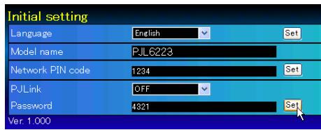
text_image
Initial setting Language English Set Model name PJL6223 Network PIN code 1234 Set PJLink OFF Set Password 4321 Set Ver. 1.000* 1 to 32 alphanumeric characters can be used for the password.
What's PJLink?
The projectors equipped with PJLink function can be used together on the same network, regardless of model or brand, for centralized control and monitoring. This standard was established by the Japan Business Machine and Information System Industries Association (JBMIA). Please visit the Website at http://pjlink.jbmia.or.jp/english/.
PJLink Notice
The projector is compliant with PJLink Standard Class 1 of JBMIA, and it supports all commands defined by PJLink Class 1 and is verified conformance with PJLink Standard Class 1.
| Projector Input | PJLink Input | Parameter | |
| Computer 2 | RGB | RGB 1 | 11 |
| Computer 1 | RGB | RGB 2 | 12 |
| Component | RGB 3 | 13 | |
| S-video | RGB 4 | 14 | |
| RGB (Scart) | RGB 5 | 15 | |
| Video | Video | VIDEO 2 | 22 |

natural_image
Blue glossy button with a white camera icon and circular design (no text or symbols)Network configuration
Click Network on the main menu. The following setting page is displayed. The IP Address, Subnet Mask, Default Gateway, DNS (Domain Name Server) and projector name are set up on this menu.
The IP address and Subnet Mask have been configured already in chapter "Installation". If you want to change them or configure default gateway or DNS, perform them in this page. If you change them, the projector begins restarting and it takes about 10 seconds. Close (Quit) the web browser and access to the login page again in 10 seconds.

text_image
Network setting LAN mode LAN1 DHCP OFF IP address 172.21.99.252 Subnet mask 255.255.255.0 Default gateway 172.21.0.1 DNS 172.21.1.53 Set Projector name Set Initial setting Power & Status PC Adj. Control Setting E-mail setting Network Information SNMP settingItem Description
LAN mode ...... Displays the selected LAN mode
DHCP....Sets DHCP configuration (ON/OFF).
IP address ......Sets IP address of the projector
Subnet mask.....Sets Subnet mask according to your network environment.
Default gateway ^*1 .....Sets IP address of the default gateway (Router)
DNS ^*2 Sets IP address of the DNS server. Must be set when using the e-mail function
Projector name ^*3 . Sets name of the projector. (64 characters maximum)
* You must use the number specified by your administrator. The address must be entered as a group with four numbers split by a dot like [192.168.001.101].

natural_image
Blue glossy button with a white envelope icon, no text or symbols present.E-mail setting
This projector has an E-mail function which can send an alert message to users or an administrator if it detects an abnormality on the projector or run out of the life span of the lamp. Click E-mail Setting on the main
menu and follow the below steps.
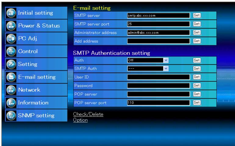
text_image
Initial setting Power & Status PC Adj. Control Setting E-mail setting Network Information SNMP setting E-mail setting SMTP server smtp.abc.xxx.com Set SMTP server port 25 Set Administrator address admin@abc.xxx.com Set Add address Set SMTP Authentication setting Auth Off Set SMTP Auth --- Set User ID Set Password Set POP server Set POP server port 110 Set Check/Delete OptionItem......Description
SMTP server ....Enter server name or IP address of the SMTP server. (up to 60 characters)
SMTP server port ......Enter Port number of the SMTP server. (from 1 to 65535)
Administrator address....Enter e-mail address of administrator.
Add address......Enter e-mail address of the user to send mail when the projector has an abnormality.
SMTP Authentication setting
Auth ....Sets authentication setting option. (Off, SMTP Auth, POP before SMTP)
SMTP Auth ....Sets user authentication setting option when selecting "SMTP Auth" in above column. (CRAM-MD5, LOGIN, PLAIN)
User ID ....Enter SMTP user ID. (up to 63 characters)
Password ......Enter SMTP password. (up to 63 characters)
POP server......Enter server name or IP address of the POP server. (up to 60 characters)
POP server port ....Enter Port number of the POP server. (from 1 to 65535)
1 Setting SMTP server and administrator address
Enter the server name or IP address of the SMTP server ^*1 , the port number of the SMTP server and administrator address and click Set button. The administrator address is set to "Reply-To" address of the message sent from the projector.
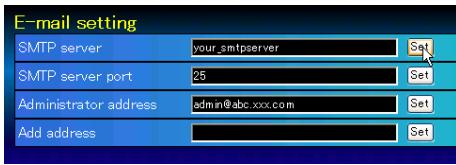
text_image
E-mail setting SMTP server your_smtpserver Set SMTP server port 25 Set Administrator address admin@abc.xxx.com Set Add address Set*1 The SMTP server is a server for sending e-mail. Please contact your network administrator to have this SMTP server address.
2 Registering and deleting E-mail addresses
Enter the e-mail address onto "Add e-mail address" and click Set button.
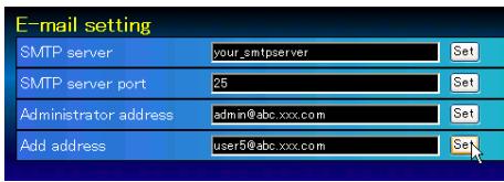
text_image
E-mail setting SMTP server your_smtpserver Set SMTP server port 25 Set Administrator address admin@abc.xxx.com Set Add address user5@abc.xxx.com SetCheck / Delete
To check the registered addresses, click Check/Delete sub menu tab. The addresses are listed as the figure on the right.

text_image
E-mail setting Check/Delete user01@abc.xxx.com ✓ user02@abc.xxx.com ✓ user03@abc.xxx.com user04@abc.xxx.com Delete Back* Up to 10 E-mail addresses can be registered.
To delete the registered addresses, check the address you want to delete and click Delete button.
3 Setting SMTP authentication
Set the SMTP authentication concerned and click Set button. Please contact your network administrator in details.
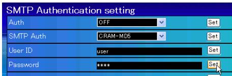
text_image
SMTP Authentication setting Auth OFF Set SMTP Auth CRAM-MD5 Set User ID user Set Password **** Set4 Setting POP server
When "POP before SMTP" is selected at "Auth" of "SMTP Authentication setting", enter "POP server*2" and "POP server port" and click Set button.
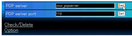
text_image
POP server your_popserver POP server port 110 Check/Delete Option*2 The POP server is a server for receiving e-mail.
Please contact your network administrator to have this POP server address.
Error message for sending alert mail
When the projector has an abnormality, an alert message will be sent to the registered E-mail address.
If the SMTP server is missing or the authentication is not completed because of input error in E-mail address setting or SMTP authentication setting when sending alert e-mail, the error message will be displayed. Please check the respective settings.
Error message for missing SMTP server
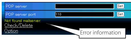
text_image
POP server POP server port 110 Set Not found mailserver. Check/Delete Option Error informationError message for authentication problem
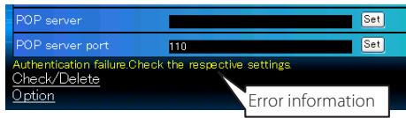
text_image
POP server POP server port 110 Set Set Authentication failure Check the respective settings Check/Delete Option Error information5 Option selection for sending alert mail
Click Option sub menu tab. Check the condition items under which alert mail will be sent and click Set button.
Please refer to item "Examples :Type and contents of alert mail" described on the next page.
Option
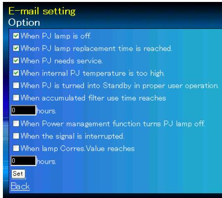
text_image
E-mail setting Option When PJ lamp is off When PJ lamp replacement time is reached. When PJ needs service. When internal PJ temperature is too high. When PJ is turned into Standby in proper user operation. When accumulated filter use time reaches 0 hours When Power management function turns PJ lamp off. When the signal is interrupted. When lamp Corres Value reaches 0 hours. Set Back* "When PJ lamp is off" signifies the lamp goes out without user operation. "When PJ is turned into Standby in proper user operation" signifies that the projector is turned on by using the web browser and then it is turned into standby with ON/STANDBY button on the top control or the remote control.
* Up to 99,999 hours can be set for use time.
Examples: Type and contents of alert mail
When the projector has an abnormality, the following alert messages are sent to the registered E-mail address according to your selected condition. Administrator or user can take an efficient action quickly by receiving this message. This is very useful to maintain and service the projector.
The following are examples of received messages.
- When internal PJ temperature is too high:
TITLE: Message from projector
Projector Model Name: model name
TCP/IP: 192.168.1.201 Projector Name: Proj05
It sends you following message.
*The Projector lamp is turned off, because internal projector temperature is too high. Wait for the completion of the cooling process and make sure the projector has been turned into Standby. Then turn the projector on again. If the Indicator continues flashing, check the air filter for dust accumulation.
- When PJ needs service:
TITLE: Message from projector
Projector Model Name: model name
TCP/IP: 192.168.1.201 Projector Name: Proj05
It sends you following message.
*Maintenance requirement from Projector is detected. Check up LED status of projector and consult with the dealer.
MCI
MAIN
3.3V
ALL
OK
NG

* The projector lamp was turned off, because the projector power circuit failed. Unplug the AC power cord and plug it, and then turn on the projector once again to verify operation. If the problem still persists, unplug the AC power cord and ask servicing to a qualified service personnel with the error information.
- When PJ lamp replacement time is reached:
TITLE: Message from projector
Projector Model Name: model name
TCP/IP: 192.168.1.201 Projector Name: Proj05
It sends you following message.
*The projector lamp has reached replacement time. Lamp ON 3000 h
* Replace it with a new lamp immediately and reset the lamp counter. If the projector is used without resetting the lamp counter, the alert mail is sent to users in every power-on of the projector. This alert mail will not be sent when unchecking the mail sending condition "When PJ lamp replacement time is reached".

natural_image
Blue circular icon with a white camera symbol and exclamation mark (no text or numbers)SNMP setting
This projector provides a SNMP (Simple Network Management Protocol) agent function. The SNMP consists of a manager and agents. The group which communicates information each other with SNMP is called
"Community". There are two access modes in a community, Refer (read only) and Set (read-write). This projector allows to use Refer (read only) only. The SNMP message informs the projector status called "Trap" to an administrator. Click SNMP Setting on the main menu and set up each item.
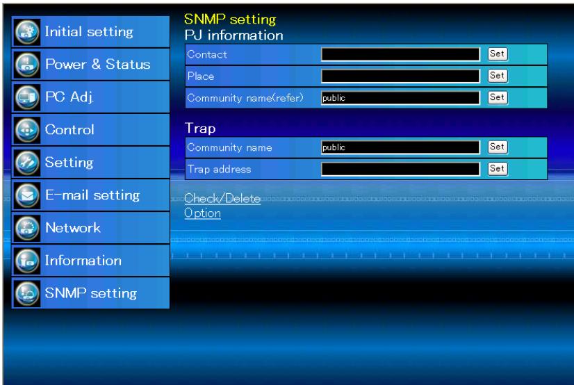
text_image
Initial setting Power & Status PC Adj. Control Setting E-mail setting Network Information SNMP setting SNMP setting PJ information Contact Set Place Set Community name(refer) public Set Trap Community name public Set Trap address Set Check/Delete OptionPJ information
Item Description
Contact....Enter user name of the projector etc. (optional)
Place ....Enter place of the projector (optional)
Community name(refer)......Enter community name (read only). Default name is "public".
Trap
Item Description
Community name....Enter community name to send "Trap". Default name is "public".
Trap address....Enter IP address of the SNMP manager computer to receive "Trap".
Trap check/delete
Check and delete the trap address
Checking the registered trap address and deleting the address.
To delete the address, tick check box in front of the IP address and click Delete button.
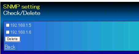
text_image
SNMP setting Check/Delete 192.168.1.5 192.168.1.6 Delete Back* Up to 10 trap addresses can be registered.
Trap option
Trap option setting
Tick check boxes in front of the condition item to send the trap.
* Click Set button if you tick or un-tick the check box on a page.
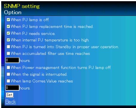
text_image
SNMP setting Option ✓ When PJ lamp is off. ✓ When PJ lamp replacement time is reached. ✓ When PJ needs service. ✓ When internal PJ temperature is too high. ■ When PJ is turned into Standby in proper user operation. ■ When accumulated filter use time reaches 0 hours. ■ When Power management function turns PJ lamp off. ■ When the signal is interrupted. ■ When lamp Corres.Value reaches 0 hours. Set BackChapter 4
Controlling the Projector
Describes controlling and setting of the projector by using the web browser.
4

natural_image
Blue glossy circular icon with a white exclamation mark symbol (no text or numbers)Power control and status check
Click Power & Status on the main menu. The control page will be displayed.
By clicking ON or Standby button on the page, the power of the projector can be controlled.

text_image
Initial setting Power & Status PJ status Power ON Status Normal PC Adj Power control ON Standby Control Setting E-mail setting Network Information SNMP setting Confirmation window as shown in the below appears when the Standby button is pressed.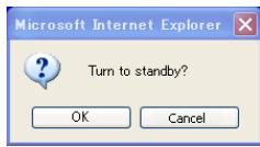
text_image
Microsoft Internet Explorer Turn to standby? OK CancelPopup confirmation window
Item
Description
PJ status
Power ......Displays the status of the lamp. (ON, OFF, On starting up, On cooling down)
Status ......Displays the status of the projector's power. (Refer to next page.)
Power control ......Controls the projector power by clicking the "ON" or "Standby" button.
* The projector cannot be turned on while the projector is on cooling down.
* The web browser checks and updates the projector's condition every 30 seconds automatically.
About projector condition
| Status | Description |
| Normal | Projector is operating normally. |
| Power management in operation | Power management is operating |
| Lamp failure | Lamp failure is occurring |
| Abnormal Temperature | The temperature of the projector became too high |
| Standby after Abnormal Temp | Projector detects abnormal temp. and sets into standby mode. |
| Power failure | Power failure has occurred inside the projector. Projector is turned off. Unplug the AC cord and ask servicing to a qualified service personnel. |
When a security (PIN code lock) has been set on the projector, you also cannot control it through the network. To control the projector through the network, unlock the security on the projector using with the projector's menu control.
Caution about turning on/off the projector via the networks
When turning on/off the projector via the networks, preset the projector as follows:
- Select "Setting" from the Projector menu.
- Select "Standby mode" from the Setting menu and set it as "Network".
If you set this function as "Network", the network part of the projector is constantly provided with power even if the projector is turned off. If you set this as Eco, then the network part will be turned off when you turn off the projector. Consequently, you cannot turn on/off the projector via the networks.

natural_image
Blue glossy circular button with a white starburst design and four-pointed arrows (no text or symbols)Control
Click Control on the main menu. The setting method differs depending on the contents of the page. Click on the page number to change pages and select desired setting items.
* Please see the owner's manual of the projector to have the further information of each control item.
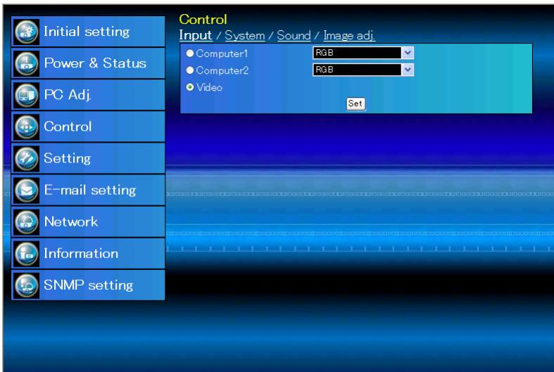
text_image
Control Input / System / Sound / Image adj. Initial setting Power & Status PC Adj. Control Setting E-mail setting Network Information SNMP setting Computer1 RGB Computer2 RGB Video SetInput
This function is to select the input mode and source mode of the projector. Click Set button after selecting the input and source mode.
Item Description
Input......Selects input mode of the projector.
Source......Selects signal source of the input.
Computer1 : RGB
Component
RGB(Scart)
S-video
Computer2: RGB
Video
System
This function is to select the system of signal input to the projector. The available system mode are listed on the pull-down menu button according to the input signal. Select a system and then click Set button.
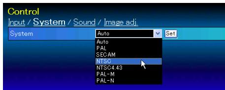
text_image
Control Input / System / Sound / Image adj. System Auto Set Auto PAL SECAM NTSC NTSC-4.43 PAL-M PAL-NAvailable selection at the RGB input
| Item | Description |
| XGA1 | It automatically switches to the proper computer system of the input signal.* The computer system modes (VGA, SVGA, XGA. SXGA, UXGA, WXGA...) which meet the input signal are listed. |
Available selection at the Video/S-video/Scart input
| Item | Description |
| AUTO...... | It automatically switches to the proper color system of the input signal.* The selectable color systems are PAL, SECAM, NTSC, NTSC4.43, PAL-M and PAL-N.* AUTO is fixed at the Scart input. |
Available selection at the Component input
| Item | Description |
| AUTO...... | It automatically switches to the proper scanning system of the input signal.* The selectable scanning systems are 480i, 576i, 480p, 576p, 720p, 1035i and 1080i. |
Sound
This function is to adjust the sound of the projector. The values in the text box represent the current control value or status.
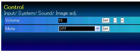
text_image
Control Input/ System/ Sound/ Image adj. Volume 15 Set Mute OFF SetItem Description
Volume ....Adjusts the sound volume from the speaker. (0 \~ 31)
Mute....Suppresses the sound. (ON, OFF)
Image adjustment
This function is to adjust the projected picture image and save the image mode. To store the adjusted value, click Store button, and to load the adjusted value, click Load button.
| Item | Description |
| Contrast | Adjusts picture contrast (0~63) |
| Brightness | Adjusts picture brightness (0~63) |
| Color | Adjusts picture color saturation (0~63) |
| Tint | Adjusts picture hue (0~63) |
| Color temp | Sets a color temperature mode. (High, Mid, Low, XLow, User) |
| White balance | |
| Red, Green, Blue | Adjusts each white balance respectively. (0~63) |
| * When changing the value of the white balance, the color temp. indicates "User". | |
| Sharpness | Adjusts picture sharpness. (0~15) |
Gamma....Adjusts brightness of darker part of the picture. (0\~ 15)
Noise reduction ...... Switches noise reduction mode (OFF, L1, L2)
Progressive....Switches progressive mode (OFF, L1, L2, Film)
Reset....Resets the Image adjustment to previous levels.
Store....Stores the Image adjustment values. Select an item [Image1 - Image4] from the pull-down menu and click Store button.
Load image mode ....Loads the Image mode. Select an image mode from the pull-down menu and click Load button. There may not be available mode depending on the input mode as shown in the table left.
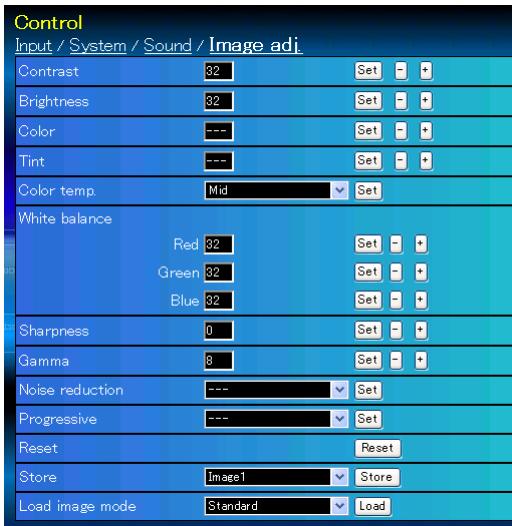
text_image
Control Input / System / Sound / Image adj. Contrast 32 Set - + Brightness 32 Set - + Color --- Set - + Tint --- Set - + Color temp. Mid Set White balance Red 32 Set - + Green 32 Set - + Blue 32 Set - + Sharpness 0 Set - + Gamma 8 Set - + Noise reduction --- Set Progressive --- Set Reset Reset Store Image1 Store Load image mode Standard Load| Input source | ||
| Image mode | Video | Computer |
| Dynamic | 4 | 4 |
| Standard | 4 | 4 |
| Cinema | 4 | * |
| Real | * | 4 |
| Blackboard(Green) | 4 | 4 |
| Colorboard | 4 | 4 |
| Image1 - 4 | 4 | 4 |
☐ The mark "4" means that the available image mode in the selected input source. The error message appears when selecting the disabled image mode indicated with "*".

natural_image
Blue circular icon with white computer monitor and tower symbol (no text or numbers)PC adjustment
Click PC Adj. on the main menu. This function is to adjust the signal from the computer connected to the projector to obtain the proper picture image on the screen.
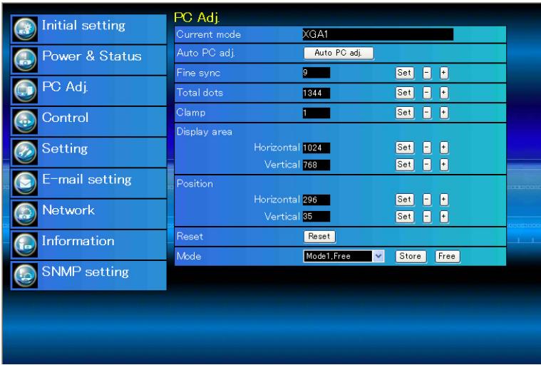
text_image
PC Adj. Current mode XGA1 Auto PC adj. Auto PC adj. Fine sync 9 Set - + Total dots 1344 Set - + Clamp 1 Set - + Display area Horizontal 1024 Set - + Vertical 768 Set - + Position Horizontal 296 Set - + Vertical 35 Set - + Reset Reset Mode Mode1,Free Store Free Initial setting Power & Status PC Adj. Control Setting E-mail setting Network Information SNMP settingItem Description
Current mode.....Displays a current mode like VGA, SVGA, XGA. SXGA, UXGA, WXGA, etc. or Mode1 - Mode10 which are the customized mode created by using the "Mode Store" function described below.
Auto PC adj......Performs automatic adjustment.
Fine sync ......Performs Fine Sync adjustment. (0 \~ 31)
Total dots ....Adjust the number of total dots in the horizontal period.
Clamp....Adjusts the phase of the clamp.
Display area
Horizontal......Adjusts the image area horizontally.
Vertical ......Adjusts the image area vertically.
Position
Horizontal .....Adjusts the horizontal position of the screen.
Vertical ....Adjusts the vertical position of the screen.
Reset......Resets the PC adjustments to the previous levels.
Mode Store......Stores the PC adjustment values. Select a mode no. [Mode1 - Mode10] from the pull-down menu.
Mode Free......Clear the PC adjustment values. Select a mode no. [Mode1 - Mode10] from the pull-down menu.

natural_image
Blue glossy circular icon with white wrench and screwdriver symbols (no text)Setting up the projector
Click Setting on the main menu. This function is to set up the projector. Select the sub menu [Screen setting] or [Setting] and then set up each setting.
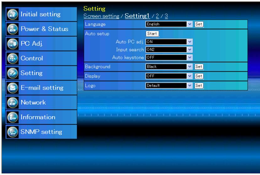
text_image
Setting Screen setting / Setting1 / 2 / 3 Language English Set Auto setup Start Auto PC adj_ON Input search_ON2 Auto keystone_OFF Background Black Set Display OFF Set Logo Default Set Initial setting Power & Status PC Adj. Control Setting E-mail setting Network Information SNMP settingScreen setting
This function is to adjust the screen mode of the projector. The values in the text box represent the current screen status.
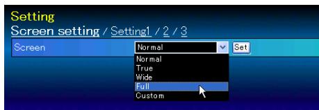
text_image
Setting Screen setting / Setting1 / 2 / 3 Screen Normal Set Normal True Wide Full CustomItem Description
Screen ...... Switches the screen mode. (Normal, True, Wide, Full, Custom) There may not be available mode depending on the input mode as shown in the table below.
| Input source | ||
| Screen mode | Video | Computer |
| Normal | 4 | 4 |
| True | * | 4 |
| Wide | 4 | 4 |
| Full | * | 4 |
| Custom | 4 | 4 |
☐ The mark "4" means that the available screen mode in the selected input source system. The error message appears when selecting the disabled screen mode indicated with "*".
Setting 1
Item Description
| Language......Sets the language display of projector's on-screen display menu. |
| Auto setup......Executes the Auto PC Adj, Input Search and Auto keystone function below according to the each setting after clicking Start button. |
| Auto PC Adj.....Sets Auto PC Adjustment mode. (ON, OFF) |
| Input search......Sets the auto-input signal detection mode. (ON1, ON2, OFF) |
Auto keystone .... Sets Auto Keystone mode. (Auto, Manual, OFF)
Background......Sets the screen background when no signal input. (Blue, User, Black)
Display....Switches on or off the on-screen menu display on the screen. (ON, OFF)
Logo ....Sets on or off the logo display on the screen during the startup. (OFF, Default, User)
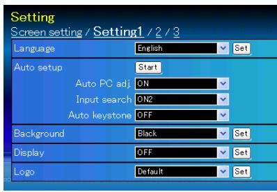
text_image
Setting Screen setting / Setting1 / 2 / 3 Language English Set Auto setup Start Auto PC adj.ON Input search.ON2 Auto keystone.OFF Background Black Set Display OFF Set Logo Default SetSetting 2
Item Description
| Ceiling......Sets the image top/bottom and left/right reversed. (ON, OFF) |
| Rear......Sets the image left/right reversed. (ON,OFF) |
| Terminal......Sets the COMPUTER IN 2/MONITOR OUT terminal. (Computer2, Monitor out) |
Power
management .....Sets into the selected power management mode (Ready, Shutdown, OFF) if
the input signal is interrupted and no control key is pressed for the specified period of time.
*The specified time can be set 1 to 30 min.
Direct on....Sets the power-on mode when the AC cord is connected to the outlet. (ON, OFF)
Lamp control.....Selects lamp control mode. (High, Normal, Eco)
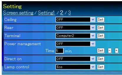
text_image
Setting Screen setting / Setting1 / 2 / 3 Ceiling OFF Set Rear OFF Set Terminal Computer2 Set Power management OFF Time 5 min Set Direct on OFF Set Lamp control Eco SetSetting 3
| Item | Description |
| Key lock......Sets the prohibition of controls either Projector or Remote control. (OFF, Projector keys, Remote control) | |
| Fan control......Sets the fan control speed. | |
| OFF Normal mode | |
| ON1 Highland mode 1 | |
| ON2 Highland mode 2 | |
| Lamp Corres. | |
| Value(h)......Displays the lamp use time (Corresponding value). Reset the time after lamp replacement. Click "Reset", a confirmation display appears, and then click "OK", the time will be reset. | |
| Filter counter......Displays the filter counter. Reset the time after filter clean-up. Click "Reset", a confirmation display appears, and then click "OK", the time will be reset. | |
| Filter warning......Sets the time to indicate the filter warning message on the screen. (OFF, 100H, 200H, 300H) | |
| Factory default...Sets all of the projector control items to the factory default setting except the following items. | |
| User Logo, Logo PIN code lock, PIN code lock, Lamp Corres. Value, Filter counter, PJ time | |
| * This function is effective for all the Network settings. | |
| No show......Sets the black out image temporarily. (ON, OFF) | |
| Freeze......Sets the image to freeze mode. (ON, OFF) | |
| Closed caption...Sets the closed caption function. | |
| Closed caption...Sets the closed caption mode. (OFF, CC1, CC2, CC3, CC4) | |
| Color......Sets the color of the contents. (Color, White) | |

natural_image
Blue glossy circular icon with a white lowercase 'i' and a camera symbol (no text or numbers)Information
This page is to display the basic information of the projector status. Click Information on the main menu.
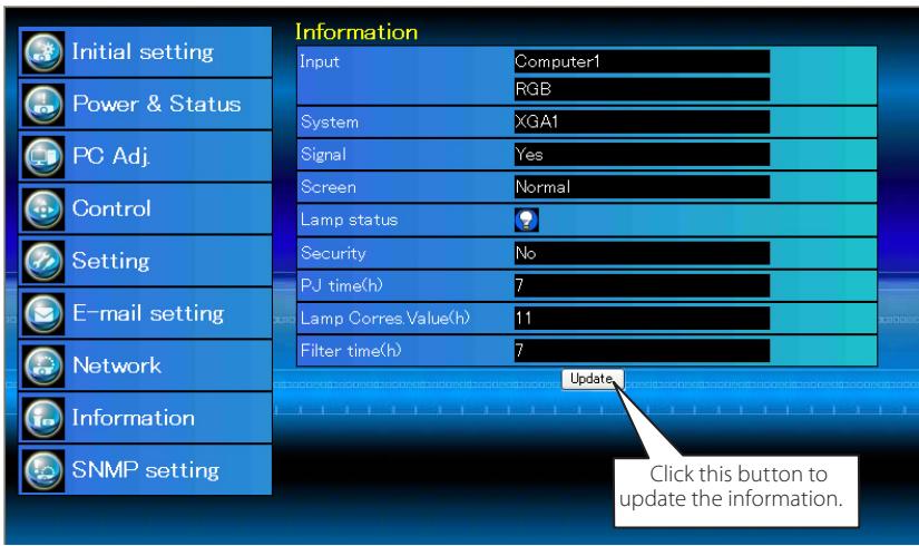
text_image
Information Input Computer1 RGB System XGA1 Signal Yes Screen Normal Lamp status Security No PJ time(h) 7 Lamp Corres Value(h) 11 Filter time(h) 7 Update Click this button to update the information. Initial setting Power & Status PC Adj. Control Setting E-mail setting Network Information SNMP setting| Items | Description |
| Input | Displays selected input and source. |
| System | Displays selected signal system. |
| Signal | Input signal status (Yes, No) |
| Screen | Displays screen mode. |
| Lamp status | Displays lamp status with an icon. Refer to the table as shown below. |
| Security | Displays the security (PIN code lock) status (Yes, No) |
| PJ time(h) | Displays the accumulated use time of the projector. |
| Lamp Corres. Value(h) | Displays the use time (Corresponding value) of the lamp. |
| Filter time(h) | Displays the accumulated use time of the filter. |
Indication of the lamp status
| Icon display/background | Status |
| Brown1 White/Blue | Lamp on (Normal) |
| Brown2 White/Red | Lamp on (Lamp is being used over a specified use time, replace lamp immediately) |
| Brown3 Gray/Blue | Lamp off (Normal) |
| Brown4 Gray/Red | Lamp off (Lamp is being used over a specified use time, replace lamp immediately) |
| Brown5 Red/Blue with X | Lamp failure (Lamp failure, check lamp condition) |
| Brown6 Red/Red with X | Lamp failure (Lamp failure and lamp is being used over a specified use time, replace lamp immediately) |
Chapter 5 Appendix
Connection examples
Use of telnet
Web browser setting
Q & A
5
Examples of connection
Peer-To-Peer connection
Connecting the projector (PJ01) to the control computer (PC05) directly.
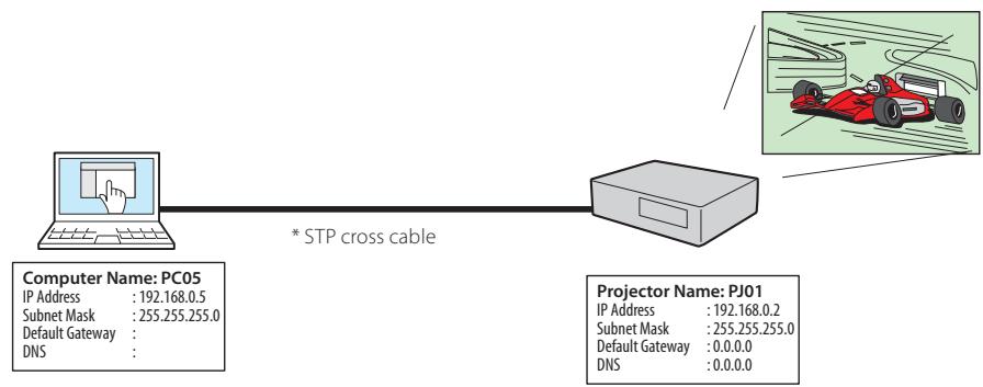
flowchart
graph LR
    A["Computer Name: PC05\nIP Address : 192.168.0.5\nSubnet Mask : 255.255.255.0\nDefault Gateway :\nDNS :"] --> B["* STP cross cable"]
    B --> C["Projector Name: PJ01\nIP Address : 192.168.0.2\nSubnet Mask : 255.255.255.0\nDefault Gateway : 0.0.0.0\nDNS : 0.0.0.0"]
Connecting the projector (PJ01) to the control computer (PC05) via the hub.
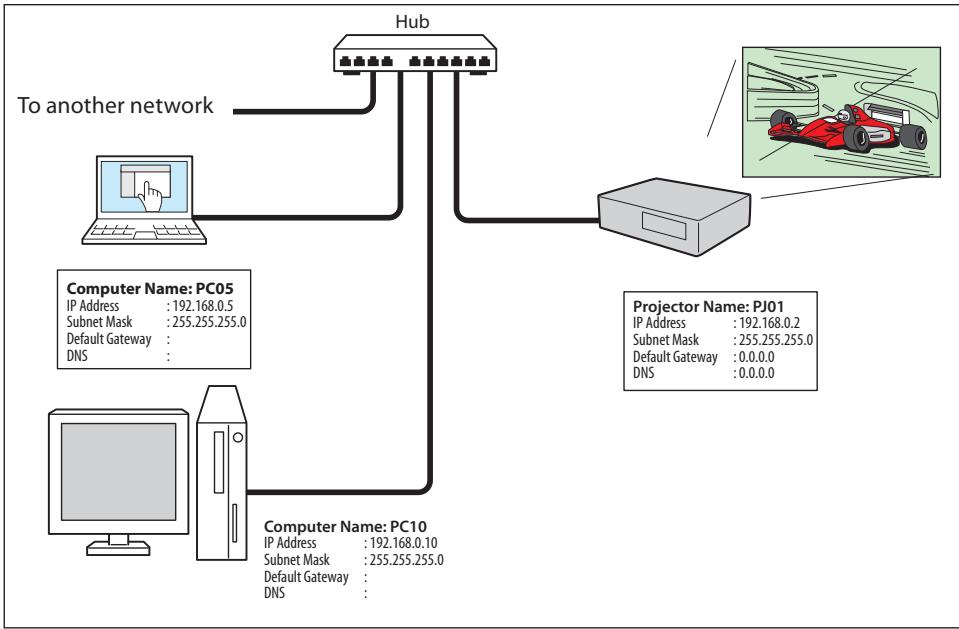
flowchart
graph TD
    Hub["Hub"] -->|To another network| PC05["Computer Name: PC05\nIP Address : 192.168.0.5\nSubnet Mask : 255.255.255.0\nDefault Gateway :\nDNS :"]
    Hub -->|To another network| PC10["Computer Name: PC10\nIP Address : 192.168.0.10\nSubnet Mask : 255.255.255.0\nDefault Gateway :\nDNS :"]
    Hub -->|To another network| Projector["Projector Name: PJ01\nIP Address : 192.168.0.2\nSubnet Mask : 255.255.255.0\nDefault Gateway : 0.0.0.0\nDNS : 0.0.0.0"]
☐ When the projector is connected to the computer directly without hub, the STP cross cable should be used.
The gateway (Router) installed in the network
Connecting the projector (PJ01) to the control computer (PC05) via the gateway.
flowchart
graph TD
    subgraph_Entrance_hall["Entrance hall"]
        A["Projector Name: PJ01"] --> B["Hub"]
        B --> C["Network Group: 192.168.200.x"]
        D["Computer Name: PC205"] --> E["IP Address: 192.168.200.5"]
        F["IP Address: 192.168.200.5"] --> G["Subnet Mask: 255.255.255.0"]
        H["Subnet Mask: 255.255.255.0"] --> I["Default Gateway: 192.168.200.1"]
        J["DNS: 192.168.201.1"] --> K["DNS: 192.168.201.1"]
    end

    subgraph_Gateway_Router["Gateway (Router)"]
        L["Port Gateway"] --> M["IP Address: 192.168.200.1"]
        N["Port Gateway"] --> O["IP Address: 192.168.100.1"]
        P["Port Gateway"] --> Q["IP Address: 192.168.10.1"]
    end

    subgraph_Office["Office"]
        R["Hub"] --> S["Computer Name: PC05"]
        T["Office"] --> U["Computer Name: PC10"]
        V["Office"] --> W["Computer Name: PC51"]
        X["Office"] --> Y["Computer Name: PC61"]
        Z["Office"] --> AA["Computer Name: PC10"]
        AB["Office"] --> AC["Computer Name: PC51"]
        AD["Office"] --> AE["Computer Name: PC61"]
    end

    style Entrance_hall fill:#f9f,stroke:#333
    style Gateway_Router fill:#ccf,stroke:#333
    style Office fill:#cfc,stroke:#333
Network Group: 192.168.10.x
Use of telnet
You can control the projector by using the telnet application ^4 installed on your computer. Normally, the telnet application is available on your computer.
* The telnet 10000 port is used to control the projector.
Control
(For example, in case of using the telnet application of Windows XP Professional.)
- Select Run... submenu from Start menu on the computer. Type "telnet" onto the Open text area on the displayed window and press OK button.
text_image
Run Type the name of a program, folder, document, or Internet resource, and Windows will open it for you. Open: telnet OK Cancel Browse...(For example, in case of using the telnet application of Mac OS X v 10.4)
- Select Terminal from Applications --> Utilities.
text_image
Macintosh HD MacDTP2 Desktop gj Applications Documents Movies Music Pictures iPhoto iSync iTunes iWeb iWork '06 Mail Network Capture 5 Office 200...Test Drive OmniOutliner Photo Booth Preview QuickTime Player Safari Sherlock Stickies System Preferences TextEdit Utilities ColorSync Utility Console DigitalColor Meter Directory Access Disk Utility Grab Grapher Installer Java Keychain Access Migration Assistant Netinfo Manager Network Utility ODBC Administrator Printer Setup Utility System Profiler Terminal VoiceOver UtilityType as below on the displayed window.
telnet [return]
text_image
Terminal — telnet — 80x24 Last login: Wed Jan 30 06:17:19 on ttyp1 Welcome to Darwin! Macintosh:~ gj$ telnet telnet>- The telnet application will start and the following window will be displayed. Type as below to connect the projector.
open 192.168.1.201 10000 [return]
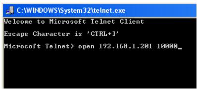
text_image
C:\WINDOWS\System32\telnet.exe Welcome to Microsoft Telnet Client Escape Character is 'CTRL+1' Microsoft Telnet> open 192.168.1.201 10000_* Use the IP address assigned to the projector.
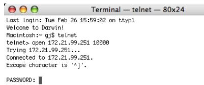
text_image
Terminal — telnet — 80x24 Last login: Tue Feb 26 15:59:02 on ttyp1 Welcome to Darwin! Macintosh:~ gj$ telnet telnet> open 172.21.99.251 10000 Trying 172.21.99.251... Connected to 172.21.99.251. Escape character is '^j'. PASSWORD:- When communication is established correctly, the word "PASSWORD:" appears on the window. Type the login password (Network PIN code ^2 ) for the projector and then press "Enter" key on the keyboard. If you do not set up the Network PIN code, just press "Enter" key.
When the word "Hello" is replied, login has been succeeded.
* The password "1234" is used for the example.

text_image
Telnet 192.168.1.201 PASSWORD: 1*2*3*4* Hello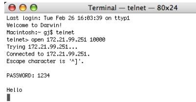
text_image
Terminal — telnet — 80x24 Last login: Tue Feb 26 16:03:39 on ttyp1 Welcome to Darwin! Macintosh:~ gj$ telnet telnet> open 172.21.99.251 10000 Trying 172.21.99.251... Connected to 172.21.99.251. Escape character is '^]'. PASSWORD: 1234 Hello- Type the commands, refer to below table, to control the projector and then press "Enter" key for termination. For example, type "C00" which is a command to turn on the projector, and press "Enter" key. Confirm the projector is turning on.
* Enter with ASCII 64-byte capital characters and one-byte characters.
To disconnect the communication, press "Ctrl" key and "] " key at the same time, type "close" and then press "Enter" key on the Keyboard.
close [return]
The table below shows the typical command lists for controlling this projector and please consult your local dealer for further information of another commands.
Command list table
| Command | Function |
| C00 | Turns the projector on |
| C01 | Shutdowns the projector directly |
| C02 | Turns the projector off |
| C09 | Volume up |
| C0A | Volume down |
| C0B | Audio Mute on |
| C0C | Audio Mute off |
| C1C | Menu display on |
| C1D | Menu display off |
*1 Further instructions about the telnet application, please see the on-line guide on your computer.
*2 The password is a Network PIN code decided item "Network PIN code setting" (pp.14, 23). If the authentication of the entered password is failed 4 times continuously, the communication will be disconnected automatically. Please try again for the connection.
☐ If the password or any command is not entered for more than 30 seconds, the communication will be disconnected automatically. Please try again for the connection.
Web browser setting
This projector is designed to be set up and controlled from an Internet web browser. Depending on the preference settings of the web browser, some control functions may not be available. Please make sure that the following functions are set up properly in the web browser.
Active Script/JavaScript enable
There are some control items used with the JavaScript function in the setting pages. If the web browser is set not to use this JavaScript function, it may not control the projector properly. In this case, the warning message "Make sure JavaScript is ON." will be displayed on the top of the page. To enable the JavaScript, please see further instructions on the next page.
Proxy setting
In some cases, your web browser is set up to use the proxy server for the internet or intranet connection. In this case, when you install this projector into the local network, you should set up the proxy setting of web browser preference correctly. Especially when connecting the projector and computer with a STP cross cable directly, or when the network does not provide the proxy server, make sure that "not use proxy server" is set up in your web browser preference. Please see item "Examples: OS/Browsers" in the next page for further setting up procedure.
Examples: OS/Browsers
Windows XP Professional
Internet Explorer v.6.0
ActiveScript setting
Select Internet Options from Tools menu on the web browser and then select Security tab and click Customize Level... button. On the security setting window, scroll down and find the Scripting item, make sure that "Enable" is selected in item Active Scripting.
text_image
Internet Options General Security Privacy Content Connections Programs Advanced Select a Web content zone to specify its security settings. Internet Local intranet Trusted sites Restricted sites Internet This zone contains all Web sites you haven't placed in other zones Security level for this zone Custom Custom settings. • To change the settings, click Custom Level. • To use the recommended settings, click Default Level. Custom Level... Default Level OK Cancel Apply
text_image
Security Settings Settings: Active scripting Disable Enable Prompt Allow paste operations via script Disable Enable Prompt Scripting of Java applets Disable Enable Prompt User Authentication Reset custom settings Reset to: Medium Reset OK CancelProxy setting
Select Internet Options from Tools menu on the web browser and then select Connection tab and click LAN Settings button. Properly set up your web browser's the proxy server settings according to the local area network environment to which the projector is connected.
- Using proxy server
To use an external internet connection from the local area network, check the item Use a proxy server and enter the proxy server address and port correctly in the proxy settings window. For further instruction please consult your network administrator.
- Not using proxy server
Uncheck the item Use a proxy server.
If you connect the projector to the computer directly with STP cross cable, this must be unchecked.
text_image
Local Area Network (LAN) Settings Automatic configuration Automatic configuration may override manual settings. To ensure the use of manual settings, disable automatic configuration. Automatically detect settings Use automatic configuration script Address: Proxy server Use a proxy server for your LAN (These settings will not apply to dial-up or VPN connections) Address: proxy.xxx.com Port: 8080 Advanced... Bypass proxy server for local addresses OK CancelTo designate proxy settings that will not use the proxy server when accessing the projector installed in the local area network, enter the IP address or domain name here.
text_image
Proxy Settings Servers Type Proxy address to use Port HTTP: proxy.xxx.com : 8080 Source: proxy.xxx.com : 8080 FTP: proxy.xxx.com : 8080 Gopher: proxy.xxx.com : 8080 Socks: ✓ Use the same proxy server for all protocols Exceptions Do not use proxy server for addresses beginning with: 192.168.1.201 Use semicolons ( ; ) to separate entries. OK CancelNetscape Navigator v.7.1
JavaScript Setting
Select Preference from Edit menu on the web browser and then select the item Advanced/Scripts & Plugins in the Category column. Make sure that the Enable JavaScript for Navigator is checked.

text_image
Preferences Category Appearance Navigator Composer Mail & Newsgroups Instant Messenger ICQ Privacy & Security Advanced Scripts & Plugins Cache Proxies HTTP Networking Software Installation Mouse Wheel System Offline & Disk Space Scripts & Plugins Enable JavaScript for Navigator Mail & Newsgroups Allow webpages to: Open a link in a new window (requires restarting Netscape) Move or resize existing windows Raise or lower windows Hide the status bar Change status bar text Change images Create or change cookies Read cookies Enable Plugins for Mail & Newsgroups OK Cancel HelpProxy setting
Select Preference from Edit menu on the web browser and then select the item Advanced/Proxies in the Category column. Properly set up your web browser's the proxy server settings according to the local area network environment to which the projector is connected.
- Using proxy server
When you use an external internet connection from the local area network, select the item Manual proxy configuration. Enter the proxy server address and port number correctly on HTTP Proxy item. For further instruction please consult your network administrator.
- Not using proxy server
Select the item Direct connection to the Internet in the proxy setting window.
If you connect the projector to the computer directly with STP cross cable, this must be selected.
To designate proxy settings that will not use the proxy server when accessing the projector installed in the local area network, enter the IP address or domain name here.
text_image
Preferences Category Appearance Navigator Composer Mail & Newsgroups Instant Messenger ICQ Privacy & Security Advanced Scripts & Plugins Cache Proxies HTTP Networking Software Installation Mouse Wheel System Offline & Disk Space Proxies Configure Proxies to Access the Internet Direct connection to the Internet Manual proxy configuration HTTP Proxy: proxy.xxxx.com Port: 8080 ≥SL Proxy: Port: 0 ETP Proxy: Port: 0 Sopher Proxy: Port: 0 SOCKS Host: Port: 0 SOCKS v4 SOCKS v5 No Proxy for: 192.168.1.201 Example: .mozilla.org, .net.nz Automatic proxy configuration URL: Reload OK Cancel HelpMAC OS X v 10.4
Safari v.3.2.1
JavaScript enable setting
Select Preferences... from Safari on the web browser and then select Security tab and check Enable JavaScript.
text_image
Security General Appearance Bookmarks Tabs RSS AutoFill Security Advanced Web Content: Enable plug-ins Enable java Enable JavaScript Block pop-up windows Accept Cookies: Always NeverProxy setting
1 Open Preferences... from Safari menu on the web browser Safari. The preference menu appears.
2 Select Advanced icon and then click Proxies: Change Settings ....
3 Select Proxies tab and properly set up your web browser Safari's the proxy server settings according to the local area network environment to which the projector is connected.
- Using proxy server
To use an external internet connection from the local area network, check the items Web Proxy (HTTP) and Secure Web Proxy (HTTPS) of Select a proxy server to configure window and enter the proxy server address and port correctly in Web Proxy Server window. For further instruction please consult your network administrator.
- Not using proxy server
Uncheck the items Web Proxy (HTTP) and Secure Web Proxy (HTTPS) of Select a proxy server to configure.
If you connect the projector to the computer directly with STP cross cable, they must be unchecked.
text_image
Advanced General Appearance Bookmarks Tabs RSS AutoFill Security Advanced Universal Access: Never use font sizes smaller than 9 Press Tab to highlight each item on a webpage Option-Tab highlights each item. Style Sheet: None Selected Proxies: Change Settings...To designate proxy settings that will not use the proxy server when accessing the projector installed in the local area network, enter the IP address or domain name here.
text_image
Network Show All Location: Automatic Show: AirMac AirPort TCP/IP PPPoE AppleTalk Proxies Configure Proxies: Manually Select a proxy server to configure: FTP Proxy Web Proxy (HTTP) Secure Web Proxy (HTTPS) Streaming Proxy (RTSP) Exclude simple hostnames Bypass proxy settings for these Hosts & Domains: 192.168.1.201 Use Passive FTP Mode (PASV) Web Proxy Server proxy.xxxx.com 8080 Proxy server requires password Set Password... Click the lock to prevent further changes. Assist me... Apply NowQ&A
Installation/Access

Why doesn't the setting page appear in my web browser?

Following causes are possible. Please check them.
- The projector does not connect to the network.
Check LED indicators status (p.12).
- Check the connection of LAN cable if the LINK Lamp does not light green.
- Check the network configuration of the projector if the ACT Lamp does not blink orange.
- Wrong network configuration of the computer.
Check the network configuration of the computer.
-
The proxy setting of the web browser is not set correctly (p.50).
-
The computer does not provide TCP/IP protocol.

How can I restrict access from the computer.

-
Please use the password authentication function on the login page ( p.23).
-
Please use the IP filtering function provided with the gateway (router) to restrict the accessing from the computer. For further information please consult your network administrator.

Can I access the projector installed on the company's local area network from a remote location?

There are some ways to access to the projector in the LAN, but you must consult your network administrator for security reason.
* Use of modem
(Connect to the company's network from your home or some other places by using modem.)
* Use of private line
(Connect to the company's network from the branch office or maintenance office by using private line.)
* Use of internet
(Connect to the company's network from your home, branch office or some other places by using the internet.)

We use the DHCP/BOOTP server to assign the IP address. Is it possible to use the projector in this network environment?

Possible. This projector supports the DHCP/BOOTP server. To use this projector in this network environment, set it up so that the DHCP/BOOTP server does not assign the IP address configured to this projector for another device on the network. Please consult your network administrator (pp.13, 24).

How can I install several projectors?

Install and configure network one by one to avoid the IP address collision each other. To configure the IP address please see item "Network configuration" (pp.12-13, 24).
Password/Login

What should I do when I forget the IP address of the projector?

You can check the IP address in the "Network information" menu.

What should I do when I forget the password (Network PIN code)?

Please set the new network PIN code in the "Network PIN code" menu.

Can I register the setting page as a web browser "Favorites" or "Bookmarks"?

Please add "Login" page to your "Favorites" or "Bookmarks". Do not add the specified setting page because it will not be able to perform the password authentication correctly.
Operation

Why can't be turned on/off with web browser?

Please make sure the settings of the projector are correct to use the projector. Please set the Standby mode of the projector's Setting menu to "Network". Refer to "4. Controlling the Projector" "Power control and status check" (pp.32 - 33).

Why can't I change the controls in the setting page with web browser?

Please make sure the projector is turned on. If it is in the standby mode, the setting is not effective to the projector. To control the projector with a web browser, the projector must be in the powered-on condition.

Why does it sometimes take a lot of time to complete the page display?

The display speed of the page depends on the network environment in which both the projector and computer are placed. It may take much time to complete the page display if network traffic is heavy. Please consult your network administrator.

How many numbers of the E-mail address can I register in the E-mail setting page.

You can register up to 10 addresses.

Why am I not receiving E-mail alert messages?

Make sure that the registered E-mail address and SMTP server address are correct. If the SMTP server is located in your LAN (Local Area Network), the address should be set to the SMTP server in your LAN. The SMTP server located outside of your LAN may not be available for security reason. For further information please contact your network administrator (p.25).
Others

What are the rules for IP address assignment?

If the network is constructed with TCP/IP protocol, a unique IP address is required for each piece of network equipment. The following are basic rules of the assignment.
Rule1
Do not configure the same IP address to the network equipment in the same network group. Each piece of equipment must be assigned a unique IP address.
If the IP address is set [192.168.x.x], the Subnet Mask should be set [255.255.255.0] for example.
Rule2
The start address [xxx.xxx.xxx.0] and the last address [xxx.xxx.xxx.255] of the IP address must not be assigned to any other equipment. These address numbers are reserved.
Rule3
The IP address must correlate to a network number. If network numbers are different between the equipment, they cannot establish communications each other. In this case, the router is placed in the networks to make the routing.

Can I control the projector by using the telnet application?

Possible. Please refer to the item "Use of telnet" (p.46 - 47).

What is the MAC address assigned to the projector?

The MAC address is displayed in "Network information" menu (p.14).

Can I update the firmware of the projector.
A
It is possible to update the firmware through the network. It is required to have a special tool for the updating. For further information please consult your local dealer. The version number of the firmware is indicated on the lower part of the "Initial setting" page.
text_image
Initial setting Language English Set Model name PJL6223 Network PIN code Set PJLink 0FF Set Password Set Ver. 1.000 Version of the firmware Initial setting Power & Status PC Adj. Control Setting E-mail setting Network InformationPJ Network Manager for Windows
Contents....2
Chapter 1 Introducing ....3
Introducing....3
SNMP 3
Trademarks....3
Operating Environment....4
Chapter 2 Set up ....5
PJ Network Manager installation....6
PJ Network Manager un-installation....6
Chapter 3 Basic Operation....7
Launching and quitting PJ Network Manager....8
Name of status window....8
Quitting PJ Network Manager....9
Menu tree 9
What's Target 9
Name of the button on the tool bar....10
Icon display for the target....10
Addition of the target 11
Editing the target....11
Deletion of the target....11
Setting up the warning value 12
Starting target monitoring....12
When happens the alert on the target 13
When happens the trap event on the target....13
What's Trap....13
Stopping monitoring the target....14
Displaying all the status information of the target 14
Setting the target group 14
Setting up the password of Telnet....15
Setting commands batch processing for multiple targets....15
Setting timer for targets....16
Setting up default setting....17
Customizing the status list....19
Viewing the alert information....22
Viewing the event log....23
Description of Event, Type, Warning column, Warning value 24
About event treatment....26
Viewing the command history....27
Storing the management file....28
Information saved to the registry 28
Registering the target information from the defined file at once....29
Format of the defined file 30
Example of the defined file....30
Login to the target equipment 31
Introducing
This PJ Network Manager is a SNMP manager software for the network equipment which supports the private MIB (Management Information Base).
By installing the PJ Network Manager to the computer, you can monitor the equipment simply such as the projector, the projection monitor and the flat display monitor connected to the network.
* The PJ Network Manager can handle our products which has a SNMP agent function.
SNMP
SNMP is an abbreviation for Simple Network Management Protocol.
On the TCP/IP network, it is the protocol to monitor and control the equipment connected to the network.
SNMP realizes the management function by reading and changing the management information called MIB with SNMP protocol between the manager (management equipment) and agent (controlled equipment) which are connected with TCP/IP network.
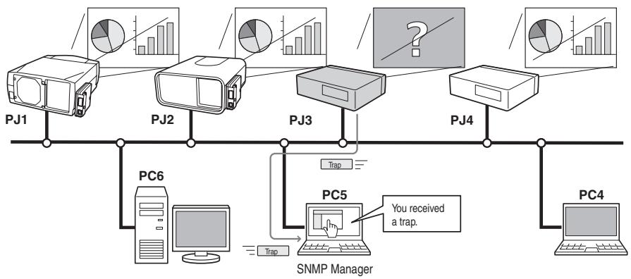
flowchart
graph TD
    PJ1[" PJ1 "] --> PC6[" PC6 "]
    PJ2[" PJ2 "] --> PC6
    PJ3[" PJ3 "] --> PC5[" PC5 "]
    PJ4[" PJ4 "] --> PC4[" PC4 "]
    PC5 -->| you received a trap. | SNMP[" SNMP Manager "]
    PC6 -->| Trap | SNMP
    SNMP -->| Trap | PC5
    subgraph Data Volumes
        A[" charts for SJMS"] --> B[" bar chart with percentage"]
        C[" pie chart with percentage"] --> D[" bar chart with percentage"]
        E[" question mark"] --> F[" bar chart with percentage"]
    end
Trademarks
Microsoft, Windows, Windows 2000, Windows XP, Windows Vista, and Windows 7 are registered trademarks of Microsoft Corporation. Macintosh is a registered trademark of Apple, Inc. in the USA and other countries. Other products or brand names in this manual are registered trademarks or trademarks of their respective owners.
* Unauthorized use of a part or whole of the contents in this manual is prohibited.
* The contents of this manual are subject to change without notice.
Operating Environment
| Item | Minimum | Recommended |
| CPU | Pentium III 400MHz or higher | Pentium 4 2.0GHz or higher for Windows XP Pentium 4 3.0GHz or higher for Windows Vista and Windows 7 |
| Memory | 128MB or higher | 256MB or higher for Windows XP 1GB or higher for Windows Vista and Windows 7 |
| HDD | More than 20MB of free disk space | |
| Screen resolution | SVGA (16 colors or more) | XGA True color or more |
| LAN | 10Mbps or more | 100Mbps or more |
| OS | Windows 2000 Windows XP Windows Vista Windows 7 | Windows XP Professional Windows Vista (32bit version) Windows 7 (32bit version) |
Limited condition
The number of agents monitored is up to 200.
Expression/Abbreviation
The OS of the computer and the Web browser described in this manual is Windows XP Professional and Internet Explorer 6.0. In case of another OS or Web browser, some instruction procedures may differ from the actual operation depending on your computer environment.
Use of this manual
This manual does not provide the description of basic operation and functions for computer, web browser, projector and network. For instructions about each piece of equipment or application software, please refer to the respective manual.
Chapter 2 Set up
2
PJ Network Manager installation
1 Set the supplied CD-ROM into the CD-ROM drive of your computer. Double click SetupTool.exe icon in the "PJ Network Manager" folder in the CD-ROM.
2 Select "[English [United States]" from the pull-down menu on the "Choose Setup Language" window and click OK button to start installing and then follow the installation wizards.
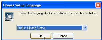
text_image
Choose Setup Language Select the language for this installation from the choices below. English (United States) OK CancelAs the "Software License Agreement" will appear, read contents carefully and click Yes button if you agree with the license agreement to proceed with installing.
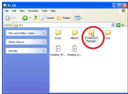
text_image
V1.00 File Edit View Favorites Tools Help Back Search Folders Address D:\ File and Folder Tasks Driver MbInfo FJ Network Manager Tool Other Places Details Readine_IP... Readine_U... Go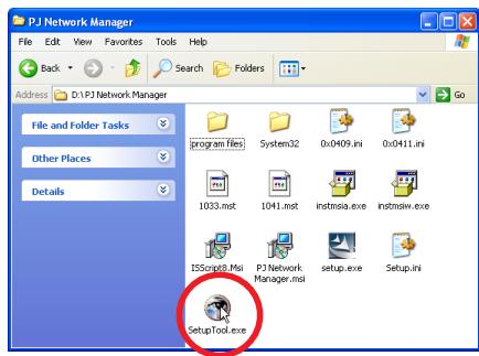
text_image
P.J Network Manager File Edit View Favorites Tools Help Back Search Folders Address D:\PJ Network Manager File and Folder Tasks Other Places Details program files System32 0x0409.ini 0x0411.ini 1033.mst 1041.mst instnsia.exe instnsiwi.exe ISScsgn8.Msi P.J Network Manager.msi setup.exe Setup.ini SetupTool.exe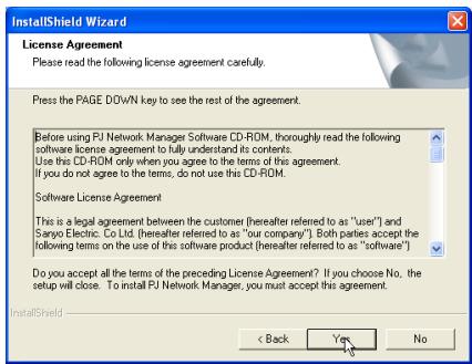
text_image
InstallShield Wizard License Agreement Please read the following license agreement carefully. Press the PAGE DOWN key to see the rest of the agreement. Before using FU Network Manager Software CD-ROM, thoroughly read the following software license agreement to fully understand its contents. Use this CD-ROM only when you agree to the terms of this agreement. If you do not agree to the terms, do not use this CD-ROM. Software License Agreement This is a legal agreement between the customer (hereafter referred to as "user") and Sanyo Electric. Co Ltd. (hereafter referred to as "our company"). Both parties accept the following terms on the use of this software product (hereafter referred to as "software"). Do you accept all the terms of the preceding License Agreement? If you choose No, the setup will close. To install FU Network Manager, you must accept this agreement. < Back Yes No
text_image
InstallShield Wizard InstallShield Wizard Complete Setup has finished installing PJ Network Manager on your computer. < Back Finish CancelNote:
To install the software into the computer with Windows 2000, Windows XP, Windows Vista, or Windows 7 you should login as administrator. Before installation, make sure that the other applications are closed, otherwise proper installation cannot be made.
PJ Network Manager un-installation
To remove the PJ Network Manager software from your computer, perform it with "Add & Remove Programs" on the control panel. (In case of Windows Vista or Windows 7, use "Programs and Features" from the control panel.)
Chapter 3
Basic Operation
3
Launching and quitting PJ Network Manager
To launch PJ Network Manager, take one of the following.
- Select "PJ Network Manager" from the menu "Start" - "All programs".
- Double click a management file ^*1 .
Name of status window
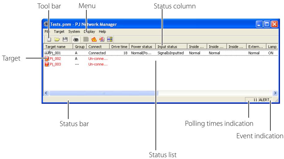
text_image
Tool bar Menu Status column Tests.pnm - PJ Network Manager File Target System Display Help Target name Group Connect Drive time Power status Input status Inside ... Inside ... Inside ... Extern... Lamp Pj_001 A Connected 18 Normal(Po... SignalIsInputted Normal Normal Normal ON Pj_002 A Un-conne... Pj_003 --- Un-conne... Status bar Polling times indication Event indication Status list* With double clicking the target name, the web browser is launching and displays login window of the target.(+p.31)
Items Description
| Menu......Executes a command with menu selection |
| Tool bar......Executes a command assigned to a button. |
| Target......Network equipment for monitoring. |
| Status bar......Indicates the status of PJ Network Manager and explaining the command selected with cursor. |
| Status list......Indicates the status of targets monitoring.When some errors are detected, the target name, icon and error items are indicated with red. |
| Status column......Column of status list. |
| Polling times indication......Indicates the times of polling during the monitoring. |
| Event indication......Indicates the event (ALERT, TRAP, SYSERR) when the event happened. |
[Note]
* The PJ Network Manager cannot open multiple status windows at the same time.
Quitting PJ Network Manager
To quit the PJ Network Manager, click the close box on top right of the status window, or select "Exit" from the "File" menu
Menu tree
| Menu | Sub menu | Operation |
| File | New | Creates a new management file. |
| Open | Opens an existing management file. | |
| Save | Saves the active management file. | |
| Save As | Saves the active management file with a new file name. | |
| Exit | Quits the application. | |
| Target | Target monitoring | Starts or stops target monitoring. |
| Target addition | Adds a new target. Target information window will appear. | |
| Target editing | Edits selected target information. | |
| Target deletion | Deletes the selected target. | |
| Group setting | Groups the selected targets. | |
| Warning value setting | Sets up the warning value of the selected target. | |
| Telnet setting | Sets up the password of telnet. | |
| Commands batch processing | Sets commands batch processing for multiple selected targets. | |
| Timer setting | Sets up the timer for the selected target. | |
| System | Target batch registration | Imports target information defined with the external file. |
| System default setting | Sets up the default setting (monitoring information, e-mail information). | |
| Column selection | Selects display items on the status list. | |
| Font setting | Sets up display font type and size on the status list. | |
| Display | Update | Updates the information on the status list display. |
| Target display | Displays selected target information. | |
| Alert display | Displays all of alert information on the status list. | |
| Event log display | Displays all the event logs. | |
| Command history display | Displays all of command history. | |
| Tool bar | Switches tool bar on or off. | |
| Help | Version information | Displays version of software. |
What's Target
Target indicates the network equipment which provides an SNMP agent function.
Name of the button on the tool bar
The following commands are assigned to the buttons on the tool bar.
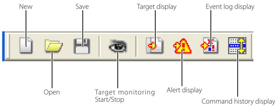
text_image
New Save Target display Event log display Open Target monitoring Start/Stop Alert display Command history displayButton
Operation
New....Creates a new management file.
Open....Opens an existing management file.
Save ....Saves the active management file.
Target monitoring ....Starts or stops target monitoring.
Target display ...... Displays selected target information.
Alert display.... Displays all of alert information on the status list.
Event log display...... Displays all the event logs.
Command history display .. Displays all of the command history.
0 To switch the tool bar display on or off, select "Tool bar" from "Display" menu.
Icon display for the target
Displays icon according to the target condition.
| Icon | Condition | ||
| Flat display type | Projector type | ||
| [63DH] | [872G] | [0086] | Normal |
 | [27FV] | [6.53T] | Abnormal condition (One of the abnormalities, Alert, Trap or System error is happening on the target.) |
| [WCZW] |  | [02X4] | Connection error (Target has been disconnected from the network) |
| [WCZW] |  | Acquisition error (Target has been disconnected from the network, or does not provide SNMP function.) | |
 | Proj_100 | Unknown (Target monitoring is not operating) | |
Addition of the target
1 Select Target Addition from Target menu. The target information registering window appears.
Items Description
| Name......Enter a management name of the target equipment. |
| IP address......Enter IP address of the target equipment. |
| Community......Enter a community name in the network. Default name is "public". |
| System information....Displays information set on the network equipment |
2 Enter target setup information and click Update button. The information set on the target equipment are displayed on the system information items.
0 When the target equipment is not operating, or it is not the monitoring equipment, the error dialog "Cannot obtain information" will appear.
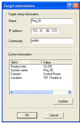
text_image
Target information Target setup information Name Proj_01 IP address 172.21.96.113 Community public System information Item Value Product info. 10.291 System name Proj_05 Contact Control Room Location 101 Theater A Update OK Cancel3 Click OK to close the window. Repeat the above steps to register for other equipment which is to be managed.
Editing the target
1 Select a target name to edit on the status list with right click.
2 Select Target editing on the popup menu. The target information window will appear and edit the contents, then click OK button.
0 The system information cannot be edited.
0 Target editing can be executed by selecting Target editing from Target menu.
Deletion of the target
1 Select a target name to delete on the status list with right click.
2 Select Target deletion on the popup menu. The confirmation dialog will appear and click Yes button to execute deleting.
0 Target deletion can be executed by selecting Target deletion from Target menu.
0 It cannot perform the target addition, editing and deletion during the target monitoring.
0 Up to 200 targets can be registered.
0 Up to 255 characters can be used for target name and community.
Setting up the warning value
PJ Network Manager provides a function to display the alert when the use time of the setting item reaches a specified setting time. The available setting items (use time) are depending on the target equipment.
1 Select a target on the status list with right click.
0 When setting multiple targets together, select targets with pressing "Shift" or "Control" key.
2 Select Warning value setting on the popup menu. The setting window will appear as the right figure.
3 Check Warning time check box. The setting items are activated. Select a setting item and click Edit button. Another setting window appears.
4 Enter the threshold value of selected item and then click OK button. The setting window will disappear.
5 Set up warning value for remaining items if available and then click OK button. The setting window will disappear.
0 To disable the warning value, clear Warning time check box.
0 When selecting multiple targets, the value set to the lowest target on the status list is displayed as the current setting time. Up to 99,999 hours can be set for the use time. The warning value is stored in the management file.
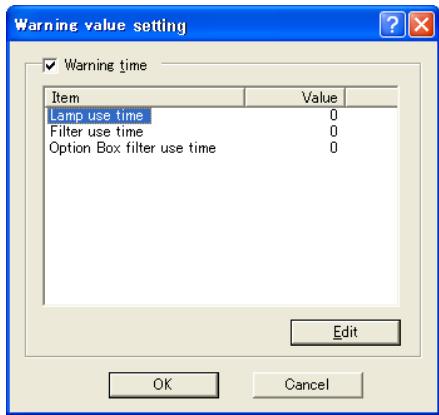
text_image
Warning value setting ✓ Warning time Item Value Lamp use time 0 Filter use time 0 Option Box filter use time 0 Edit OK Cancel(Example of the set up window)
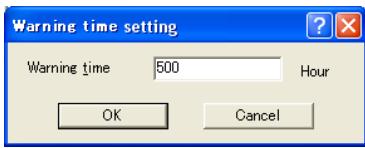
text_image
Warning time setting Warning time 500 Hour OK CancelStarting target monitoring
1 Click button on the tool bar to start monitoring the target.
2 PJ Network Manager starts polling the target in a sequential from the top of the status list and displays the results on the status list.
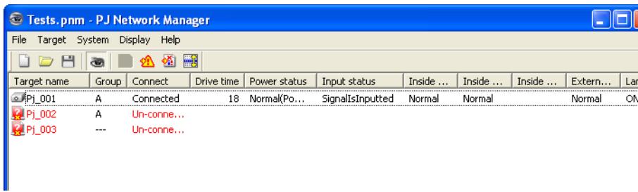
text_image
Tests.pnm - PJ Network Manager File Target System Display Help Target name Group Connect Drive time Power status.Input status Inside ... Inside ... Inside ... External... Lan Pj_001 A Connected 18 Normal(Po... SignalIsInputted Normal Normal Normal ON Pj_002 A Un-conne... Pj_003 --- Un-conne...When happens the alert on the target
If the abnormality or connection error happens on the target, PJ Network Manager indicates target name, icon and status column item with red color to let you know the abnormality.
0 When PJ Network Manager cannot acquire the MIB information of the target equipment, it indicates as Connection Error.
0 The interval of target monitoring is according to the setting of Monitoring interval on System default setting from System menu. (+p.17)
0 For the way to give notice of the alert information, refer to Event reception process on System default setting from System menu. (+p.17)
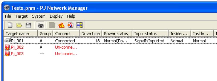
text_image
Tests.pnm - PJ Network Manager File Target System Display Help Target name Group Connect Drive time Power status.Input status Inside ... Inside ... I Pj_001 A Connected 18 Normal(Po... SignalIsInputted Normal Normal Pj_002 A Un-conne... Pj_003 --- Un-conne...When happens the trap event on the target
During the target monitoring, if the predefined event (trap) happens on the target equipment, the target sends the trap information to PJ Network Manager. This trap information is displayed on the status list.
The trap information is set up in the SNMP setting items of the target equipment. Projector has items such as "When PJ lamp is off", "When the life span of lamp is reached", "When internal PJ power circuit is failed" etc. For further trap information, refer to "SNMP setting" in the separated network owner's manual.
0 For the way to give notice of the trap information, refer to Event reception process on System default setting from System menu. (+p.17)
What's Trap
Trap is the event predefined by the SNMP agent. If the predefined event ("When PJ lamp is off", "When internal PJ power circuit is failed" etc.) happens, target sends trap information to the SNMP manager.
Stopping monitoring the target
To stop monitoring the target, click 📄 button again on the tool bar.
Displaying all the status information of the target
Select a target and click ➕ button on the tool bar. The following status window appears and displays all the available status information of the target.
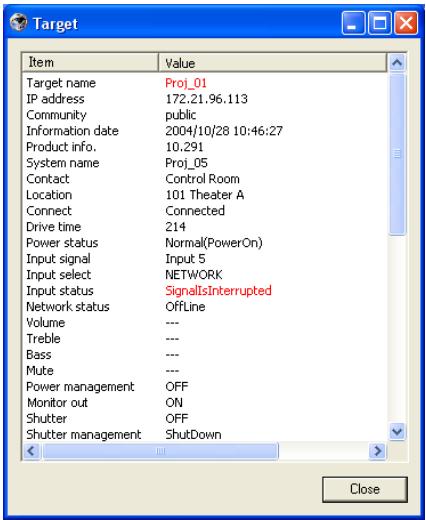
text_image
Target Item Value Target name Proj_01 IP address 172.21.96.113 Community public Information date 2004/10/28 10:46:27 Product info. 10.291 System name Proj_05 Contact Control Room Location 101 Theater A Connect Connected Drive time 214 Power status.Normal(PowerOn) Input signal.Input 5 Input select NETWORK Input status SignalInterrupted Network status Offline Volume --- Treble --- Bass --- Mute --- Power management OFF Monitor out ON Shutter OFF Shutter management Shutdown < > Close0 The target name and item which have an abnormality or connection error happening are indicated with red.
0 When PJ Network Manager cannot acquire the value of column information, "---" is displayed.
0 The above procedure can perform by selecting Target display from Display menu.
Setting the target group
The target group can be set up by the procedure below. When you set a command in the same group, you set it.
1 Select targets which you want to set from the status list. Select Group setting from Target menu, the dialog box will appear as the below figure.
2 Select a group, and then click OK button.
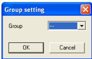
text_image
Group setting Group OK Cancel0 "---" will not set the group.
0 The projectors setting different network passwords cannot be set to the same group. It is necessary for the projectors in the same group to set to the same password.
Setting up the password of Telnet
The password of telnet can be set up by the procedure below. It is necessary to make a password, same as the network password.
1 Select a target which you want to set up the password of telnet from the status list. You can select multiple targets.
2 Select Telnet setting from Target menu, Telnet setting dialog box will appear as the below figure. Set a password and click OK button. When multiple targets are selected, all the selected targets are set as the same password.
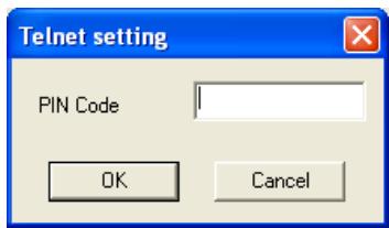
text_image
Telnet setting PIN Code OK Cancel0 The initial setting is "0000".
Setting commands batch processing for multiple targets
The commands batch processing for multiple targets can be set up by the procedure below.
1 Select a target belonging to the batch processing group which you want to set, and select Commands batch processing from Target menu. Commands batch processing dialog box will appear as the below figure.
2 Select a command which you want to set, click Edit button. Parameter editing dialog box will appear. Select a parameter, and then click OK button. The check box of Commands batch processing dialog box will be checked.
3 Click OK button. The commands are carried out to all the targets of the same group.
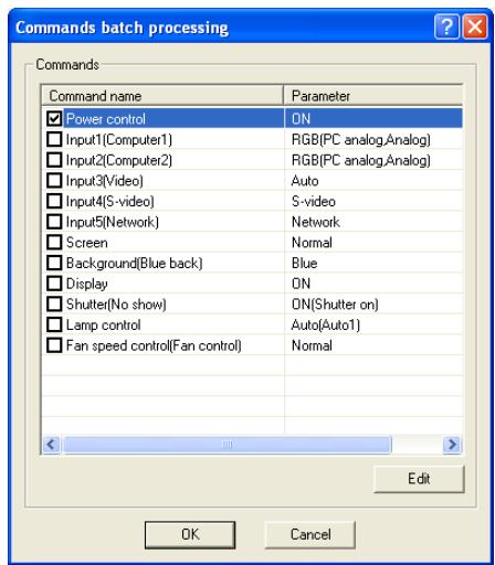
text_image
Commands batch processing Commands Command name Parameter Power control ON Input1(Computer1) RGB(PC analog,Analog) Input2(Computer2) RGB(PC analog,Analog) Input3(Video) Auto Input4(S-video) S-video Input5(Network) Network Screen Normal Background(Blue back) Blue Display ON Shutter(No show) ON(Shutter on) Lamp control Auto(Auto1) Fan speed control(Fan control) Normal Edit OK Cancel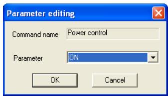
text_image
Parameter editing Command name Power control Parameter ON OK Cancel0 The commands also work for the target which is not set to a group.
Commands batch processing : Available Command Items Description
| Power ON/OFF......Sets up the Power ON or Power OFF. |
| Input,Source......Sets up the Input and Source. Selects Input and Source. |
| Screen......Sets up the screen size. Resizes the picture screen. |
| Background......Sets up the background. Selects the background screen for when no input signal is detected. |
| Display......Sets up the Display. Decides whether to display On-Screen Displays or not. |
| Shutter(No show)......Sets up the Shutter (No show). Sets black out the image. |
| Lamp control......Sets up the Lamp control. Changes brightness of the screen. |
| Fan control......Sets up the Fan control. Chooses the running speed of cooling fans. |
Setting timer for targets
The timer information for targets can be set up by the procedure below.
1 Choose a target which you want to set the timer.
2 Select Timer setting from Target menu. Timer selection dialog box will appear as the below figure. Check in a check box of an event to carry out.
3 When you want to add events, click Add button. Input timer informations in Timer setting dialog box, and click OK button.
4 Click OK button of Timer selection dialog box, timers are set to the selected target. When selecting multiple targets, timers are set to all the selected targets.
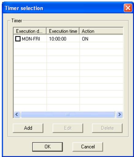
text_image
Timer selection Timer Execution d... Execution time Action MON-FRI 10:00:00 ON Add Edit Delete OK Cancel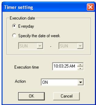
text_image
Timer setting Execution date Everyday Specify the date of week SUN SUN Execution time 10:03:25 AM Action ON OK CancelTimer
Items Description
Execution date....Sets up the Timer execution date. (everyday or a day)
Execution time....Sets up the Timer execution time. (hh:mm:ss)
Action ....Sets up the events.
Setting up default setting
The monitoring information and e-mail information can be set up by the procedure below.
1 Select System default setting from System menu. The setting window will appear.
2 Switch by clicking Monitoring information or E-mail information tab for each setting.
Monitoring information
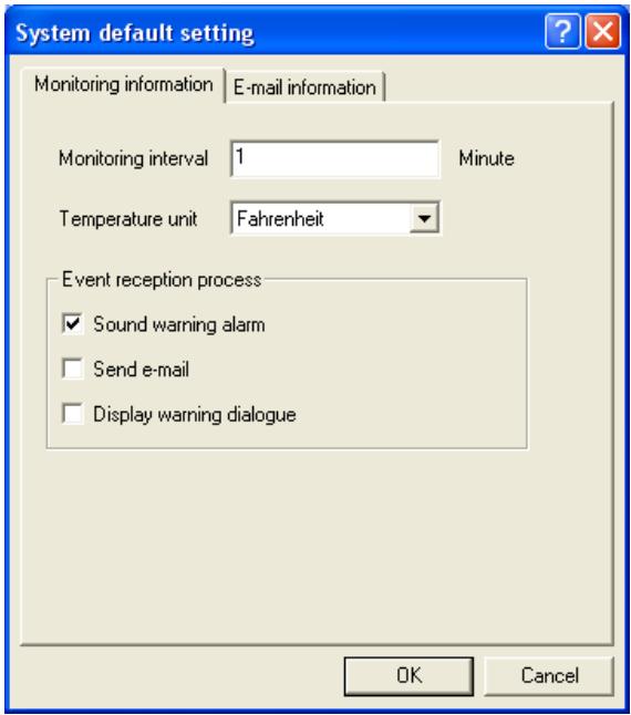
text_image
System default setting Monitoring information E-mail information Monitoring interval 1 Minute Temperature unit Fahrenheit Event reception process ✓ Sound warning alarm ☐ Send e-mail ☐ Display warning dialogue OK CancelMonitoring information
Items Description
Monitoring interval ....Sets up the interval of the polling in minute unit. (1 to 99 minutes can be set)
Temperature unit....Sets up the display temperature unit Centigrade or Fahrenheit.
Event reception process......Sets up the treatment when the event (ALERT, TRAP, SYSERR) happens on the target.
For further information, refer to the item "About event treatment" (+p.26).
p Sound warning alarm
p Send e-mail
p Display warning dialog
E-mail information
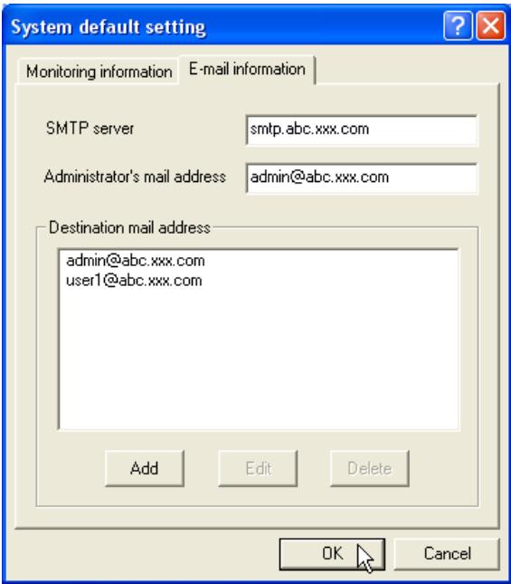
text_image
System default setting Monitoring information E-mail information SMTP server smtp.abc.xxx.com Administrator's mail address admin@abc.xxx.com Destination mail address admin@abc.xxx.com user1@abc.xxx.com Add Edit Delete OK CancelE-mail information
Items Description
SMTP server ....Sets up the IP address of SMTP mail server or server host name.
Administrator's
mail address....Sets up the e-mail address of administrator
Destination mail
address......Sets up the destination mail address when the event (ALERT, TRAP, SYSERR) happens on the target. The mail address entering window appears when clicking Add button.
Customizing the status list
Changing the status column indication
1 Select Column selection from System menu. The column selection window will appear.
2 On the window, check the column name to be indicated on the status list.
0 The mark [*] next to the column name indicates alert item.
3 To change the order of the display column on the status list, select a column you intend to change the order and click To up or To down button.
4 Click OK to close setting.
0 When specifying the column width by numeric value, enter number (0 to 9999) onto "Column width" text box.
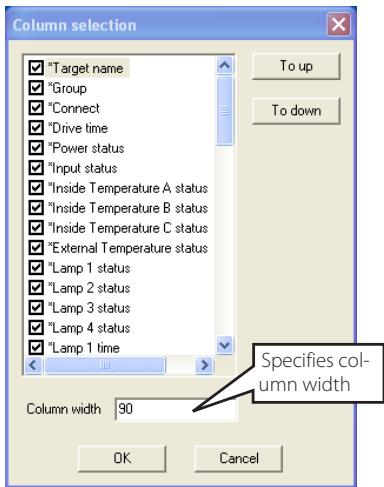
text_image
Column selection ✓ "Target name" ✓ "Group" ✓ "Connect" ✓ "Drive time" ✓ "Power status" ✓ "Input status" ✓ "Inside Temperature A status" ✓ "Inside Temperature B status" ✓ "Inside Temperature C status" ✓ "External Temperature status" ✓ "Lamp 1 status" ✓ "Lamp 2 status" ✓ "Lamp 3 status" ✓ "Lamp 4 status" ✓ "Lamp 1 time" Column width 90 To up To down Specifies column width OK CancelColumn
Description
*Target name....Name of the network equipment
*Group Group name
*Connect....Status of connection to the network (Connected, Un-connected)
*Drive time ......Accumulated use time of the equipment
*Power status....Power status of the equipment (Normal(Power-on), Normal(Standby), Power Management, Power failure, lamp failure, etc.)
*Input status....Input signal status (Signal, No signal, Signal interrupted)
*Inside Temperature
A status....Status of inside temperature A (Normal, Warning, Error)
*Inside Temperature
B status....Status of inside temperature B (Normal, Warning, Error)
*Inside Temperature
C status....Status of inside temperature C (Normal, Error)
*External Temperature
status......Status of external temperature (Normal, Warning, Error)
*Lamp1 status....Status of Lamp1 (Off, On, Error, Replace)
*Lamp2 status....Status of Lamp2 (Off, On, Error, Replace)
*Lamp3 status....Status of Lamp3 (Off, On, Error, Replace)
*Lamp4 status....Status of Lamp4 (Off, On, Error, Replace)
*Lamp1 time.....Used time of Lamp1
*Lamp2 time.....Used time of Lamp2
*Lamp3 time.....Used time of Lamp3
*Lamp4 time.....Used time of Lamp4
*Filter status....Status of airfilter (Normal, Clogged)
*Option Box
filter status ......Status of option box filter (Normal, Error, Clogged)
*Filter time.....Use time of airfilter
*Option Box
filter time.....Use time of option box filter
0 The values in parentheses are typical value and they differ depending on the connected equipment.
0 The [*] next to the column name indicates alert items.
| Column | Description |
| *Error info. | Error information (Not available for the projector) |
| IP address | IP address of the network equipment |
| Community | Community name of the network equipment (public) |
| Introduction date*1 | Date of the network equipment installed |
| Timer | Timer information |
| Product info. | Name of the network equipment |
| System name | System name of the network equipment (Proj_05) |
| Contact | Contact information of the network equipment |
| Location | Installed location of the network equipment |
| Input signal | Information of the input mode (Input1, Input2, etc.) |
| Input select | Information of the input source (RGB, VIDEO, S-VIDEO, NETWORK, etc.) |
| Network status | Condition of the network mode (Off line, Network Viewer, Network Capture) |
| Audio system | Displays audio system mode (NORMAL, PERSONAL, MUSIC, TALK) |
| Volume | Sound Volume of the network equipment |
| Treble | Sound treble of the network equipment |
| Bass | Sound bass of the network equipment |
| Balance | Sound balance of the network equipment |
| Mute | Sound mute status of the network equipment (ON, OFF) |
| Power management | Power management status of the network equipment (OFF, READY, SHUTDOWN) |
| Monitor out | Monitor out status of the network equipment (ON, OFF) |
| Shutter (No show) | Shutter status of the network equipment (OFF, High-Contrast, Normal) |
| Shutter management | Shutter management status of the network equipment (Shutdown) |
| Fan control | Fan control status of the network equipment (Normal, Maximum, OFF, On1, etc.) |
| Inside Temperature A | Displays inside temperature A of the equipment (in Centigrade or Fahrenheit) |
| Inside Temperature B | Displays inside temperature B of the equipment (in Centigrade or Fahrenheit) |
| Inside Temperature C | Displays inside temperature C of the equipment (in Centigrade or Fahrenheit) |
| External Temperature | Displays external temperature of the equipment (in Centigrade or Fahrenheit) |
| Lamp mode | Displays lamp mode (1: 1-lamp mode, 2: 2-lamp mode, 4: 4-lamp mode, etc.) |
| Lamp control | Displays lamp control mode (Auto, Normal, Eco, etc.) |
| Model name | Model name of the network equipment |
To change order or width of the column
Drag the status column name you want to change the order and move it on a new place and drop it. To change column width, set a mouse cursor onto the right edge of the column to change, drag the mouse on it and adjust the column width.
Sorting the status list
The order of the targets on the status list can be changed by clicking the column name which you want to sort. It switches ascending or descending order by clicking the column name each time.
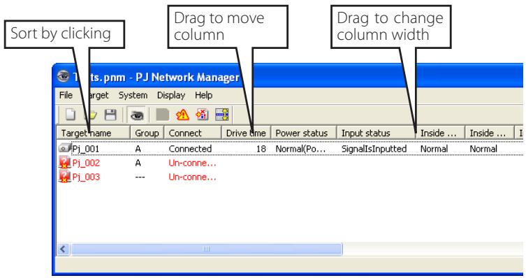
text_image
Sort by clicking Drag to move column Drag to change column width P.J Network Manager File Target System Display Help Target name Group Connect Drive time Power status Input status Inside ... Inside ... I P1_001 A Connected 18 Normal(Po... SignalsInputted Normal Normal P1_002 A Un-conne... P1_003 --- Un-conne...Changing font
Select Font setting from System menu. The font setup window will appear. Select your desired type face, style and size on the window.
text_image
Font Font: Tahoma O Tahoma Terminal Times New Roman Trebuchet MS Tunga Verdana Webdings Font style: Regular Regular Italic Bold Bold Italic Size: 8 9 10 11 12 14 16 OK Cancel Sample AaBbYyZz Script: Western0 Customized font property is applied to all the windows of the setting.
Viewing the alert information
1 Click 🔒 button on the tool bar. The alert display window appears and the alert information of all the targets which are having an alert is listed on this window as the below.
2 To export the alert information as text file (CSV file), click Export button.
text_image
Alert Target name Group Connect Drive time Power ....Input s... Inside ... Inside ... Insid Proj_01 A Connec... 212 Normal... SignalI... Normal Normal Norm Proj_10 A Connec... 234 Temper... NoSignal Abnormal Abnormal Abnc Proj_105 --- Acquisi... < III > Export Close0 Column width can be changed with dragging the right edge of the column. The column order can be changed with drag and drop the column. Column can not be deleted.
Viewing the event log
1 Click 📋 button on the tool bar. The event log display window appears and the events which have been happened on the targets are listed on this window as the below.
2 To export these events as text file (CSV file), click Export button.
3 To delete the event log, select the accrual date item you intend to delete by clicking and then click Delete button. On the confirmation dialog, click Yes to execute deletion.
text_image
Accrual date 2004/10/29 14:46:24 2004/10/29 14:46:24 2004/10/29 14:22:59 2004/10/29 14:22:59 2004/10/29 14:22:58 2004/10/29 14:05:58 2004/10/29 13:47:58 2004/10/29 13:47:12 2004/10/29 13:44:21 2004/10/29 13:26:57 2004/10/29 13:16:58 2004/10/29 13:16:04 2004/10/29 13:11:43 2004/10/29 13:10:58 2004/10/29 13:10:58 2004/10/29 13:10:00 2004/10/29 13:09:58 2004/10/29 12:38:58 Proj_10 Proj_10 Proj_10 Proj_10 Proj_10 Proj_10 Proj_10 Proj_10 Proj_10 Proj_10 Proj_10 Proj_10 Proj_10 Proj_10 Proj_10 Proj_10 Proj_10 Proj_10 Proj_10 Proj_10 Proj_10 Proj_10 PROJ_10 Proj_10 Proj_10 Proj_10 Proj_10 Proj_10 Proj_10 Proj_10 Proj_10 Proj_10 Proj_10 Proj_10 Proj_10 Proj_10 Proj_10 Proj_10 Proj_10 Proj_10 Proj_10 Proj_10 Project Project Project Project Project Project Project Project Project Project Project Project Project Project Project Project Project Project Project Project Project Project Project Project Project Project Project Project Project Project Project Project Project Project Project Project Project Project Project Project Project Project Project Project Project Project Project Project Project Project 项目信息表信息表信息表信息表信息表信息表信息表信息表信息表信息表信息表信息表信息表信息表信息表信息表信息表信息表信息表信息表信息表信息表信息表信息表信息表信息表信息表信息表信息表信息表信息表信息表信息表信息表信息表信息表信息表信息表信息表信息表信息表信息表信息表信息表信息表信息表信息表信息表信息表信息表信息table_caption<|ref_end|><|rotate_up|> Projection Box file... Error... Clogged... Error... Clogged... Connected... SignalIsInterru... SignalIsInterru... SignalIsInterru... SignalIsInterru... SignalIsInterru... SignalIsInterru... SignalIsInterru... SignalIsInterru... SignalIsInterru... SignalIsInterru... SignalIsInterru... SignalIsInterru... SignalIsInterru... SignalIsInterru... SignalIsInterru... SignalIsInterru... SignalIsInterru... SignalIsInterer... SignalIsInterer... SignalIsInterer... SignalIsInterer... SignalIsInterer... SignalIsInterer... SignalIsInterer... SignalIsInterer... SignalIsInterer... SignalIsInterer... SignalIsInterer... SignalIsInterer... SignalIsInterer... SignalIsInterer... SignalIsInterer... SignalIsInterer... SignalIsInterer... SignalIsInterer... SignalIsInterer... SignalIsInterer... SignalIsIntere... SignalIsIntere... SignalIsIntere... SignalIsIntere... SignalIsIntere... SignalIsIntere... SignalIsIntere... SignalIsIntere... SignalIsIntere... SignalIsIntere... SignalIsIntere... SignalIsIntere... SignalIsIntere... SignalIsIntere... SignalIsIntere... SignalIsIntere... SignalIsIntere... SignalIsIntere... SignalIsIntere... SignalIsIntere... SignalIsInterer...? SignalIsInterer...? SignalIsInterer...? SignalIsInterer...? SignalIsInterer...? SignalIsInterer...? SignalIsInterer...? SignalIsInterer...? SignalIsInterer...? SignalIsInterer...? SignalIsInterer...? SignalIsInterer...? SignalIsInterer...? SignalIsInterer...? SignalIsInterer...? SignalIsInterer...? SignalIsInterer...? SignalIsInteren...? SignalIsInteren...? SignalIsInteren...? SignalIsInteren...? SignalIsInteren...? SignalIsInteren...? SignalIsInteren...? SignalIsInteren...? SignalIsInteren...? SignalIsInteren...? SignalIsInteren...? SignalIsInteren...? SignalIsInteren...? SignalIsInteren...? SignalIsInteren...? SignalIsInteren...? SignalIsInteren...? SignalisInterru... SignalisInterru... SignalisInterru... SignalisInterru... SignalisInterru... SignalisInterru... SignalisInterru... SignalisInterru... SignalisInterru... SignalisInterru... SignalisInterru... SignalisInterru... SignalisInterru... SignalisInterru... SignalisInterru... SignalisInterru... SignalisInterru... SignalisInterror... SignalisInterror... SignalisInterror... SignalisInterror... SignalisInterror... SignalisInterror... SignalisInterror... SignalisInterror... SignalisInterror... SignalisInterror... SignalisInterror... SignalisInterror... SignalisInterror... SignalisInterror... SignalisInterror... SignalisInterror: Resulting from the Event Log (Event Log) Output: Export: CloseEvent log information items
Items Description
Accrual date ...... Accrual date of the event
Target name.....Name of the network equipment
IP address......IP address of the network equipment
Event .... Type of the Event (ALERT, TRAP, SYSERR) (See table on the next page)
Type ...... Type of the Event (See table on the next page)
Warning column...... Warning column of the Event (See table on the next page)
Warning value .... Warning value of the Event (See table on the next page)
Unit...... Displays unit of the warning value.
0 The listed items are fixed.
0 The order of the event log list can be changed temporarily by clicking the column name which you want to sort. It switches ascending or descending order by clicking the column name each time.
0 Column width can be changed by dragging the right edge of the column. The column order can be changed with drag and drop the column. Column cannot be deleted.
Description of Event, Type, Warning column, Warning value
| Event | Type | Warning Column | Warning Value | Description |
| ALERT | ON : Abnormality has happenedOFF : Abnormality has been cleared | Connect | Un-connectedConnectedAcquisition error | * Refer to the next page |
| Power status | PowerFailureTemperatureErrorNormal (AfterTempError)RS232CFailurePower managementShutter managementLampFailureNormal(Standby)Normal(OnStartingUp)Normal(OnCoolingDown)Normal(PowerOn)TemperatureError(OnCoolingDown)Power management(OnCoolingDown)Shutter management(OnCoolingDown)LampFailure(OnCoolingDown) | |||
| Input status | SignalsInterruptedSignalsInputted | |||
| Inside Temperature status (A to C)External Temperature status | Abnormal | |||
| Lamp status (1 to 4) | FailureReplace | |||
| Lamp time (1 to 4) | (setting time) | |||
| Filter status | CloggedWarning | |||
| Filter time | (setting time) | |||
| TRAP | LampFailure | Lamp status (1 to 4) | Failure | |
| LampReplace | Replace | |||
| PowerOFFPowreFailurePowerManagementShutterManagement | Power status | Normal(Standby)Normal(OnCoolingDown)PowerFailurePower managementPower management(OnCoolingDown)ShutterManagementShutterManagement(OnCoolingDown) | ||
| TemperatureError | Inside Temperature status (A to C)External Temperature status | Abnormal | ||
| SignallsInterrupted | Input status | SignallsInterrupted | ||
| LampReplacementTime | Lamp time (1-4) | (lamp time) | ||
| FilterReplacementTime | Filter time | (filter time) | ||
| CloggedFilterWarning | Filter status | CloggedWarning | ||
| AutoPlayError | n/a | Error | ||
| WarningOnConstantModeForBrightness | n/a | n/a | ||
| SYSERR | *Mail Transfer*MemoryError | n/a *1 | n/a *1 |
Description of warning value
| Warning Column | Warning Value | Description |
| Connect | Un-connectedConnected *Acquisition error | Projector has been disconnected from the networkProjector has been connected to the networkPJ Network Manager could not acquire the MIB information from the equipment |
| Power status | Power failure | Projector turned off due to the power failure of the projector |
| TemperatureError | The projector turned off due to temperature error occurred | |
| Normal (AfterTempError) | Normal after temperature error occurred | |
| RS232CFailure | The RS-232C communication error occurred | |
| Power management | The power management function turned projector lamp off | |
| Shutter management | The shutter management function turned projector lamp off | |
| LampFailure | The lamp failure occurred | |
| Normal(Standby) * | Projector turned into standby normally | |
| Normal(OnCoolingDown) * | On cooling down normally due to projector turned off | |
| Input signal status | SignalsInterruptedSignalsInputted * | The signal was interruptedThe signal was inputted again |
| Inside Temperature status (A to C)External Temperature status | Abnormal | The projector turned off when the temperature was abnormally high |
| Lamp status | ON *FailureReplace | When the lamp is onWhen the lamp failed to ignite.It reached lamp replacing time. |
| Lamp time | (lamp time) | It reached user setting lamp replacing time |
| Filter status | CloggedWarning | Filter has been cloggedFilter is close to clogging |
| Filter time | (filter time) | It reached user setting filter time |
| (Auto play error) | n/a | The error occurred during the auto image display |
| (WarningOnConstantModeFor Brightness) | n/a | The brightness (Current value) continuously goes down a certain rate from the value in Constant mode. |
0 The warning value with "*" in the above table shows the event when the alert has cleared, alert type is "OFF".
About event treatment
If the PJ Network Manager receives an event, it executes following event treatment items which are selected in the system default setting.
p Sound warning alarm
p Send e-mail
p Display warning dialog
Sound warning alarm
If the PJ Network Manager receives an event, the computer beeps an alarm sound. The alarm sound is depending on your computer sound setting.
0 The alarm sound is not made when your computer does not provide any speaker or the sound volume is muted.
Send e-mail
Following example message is sent to the e-mail address you set up as the destination mail address.
| From: Test1<admin@abc.xxx.com> (management file name) |
| Date : 2004/10/29 21:30 |
| To : user@abc.xxx.com |
| Subject : Alert message |
Alert has occurred
* Accrual date : 2004/10/29 21:13:42
* Target name : Proj_10
* IP address : 192.168.1.101
* Event : ALERT
* Type : ON
* Warning column : Power status
* Warning value : Power failure
0 For the further information of event, type, warning column and warning value, see the item "Viewing the event log" (+p.23).
0 The setting of event treatment, refer to item "Setting up default setting" (+p.17).
Notes on using Windows XP / Windows Vista / Windows 7
Windows Firewall is turned on by default in Windows XP, Windows Vista, and Windows 7. Due to this Windows Firewall, the send e-mail function is not available. When using this mail function, you need to cancel the block for PJ Network Manager application. For the further details of Windows Firewall, see Windows help on your computer.
Display warning dialog
Following dialog window appears on the screen if event occurs.
text_image
Event information Alert has occurred. Item Value Accrual date 2004/10/29 16:00:39 Target name Proj_01 IP address 172.21.96.113 Event ALERT Type ON Warning column.Input status Warning value SignallsInterrupted Number of 1 CloseViewing the command history
1 Click button on the tool bar. Command history window appears and the command history is listed on the window as shown below.
2 To export the command history as text file (CSV file), click Export button.
3 To delete the command history, select the item of Executed date/time which you want to delete, and then click Delete button. On the confirmation dialog box, click Yes button to execute deletion.
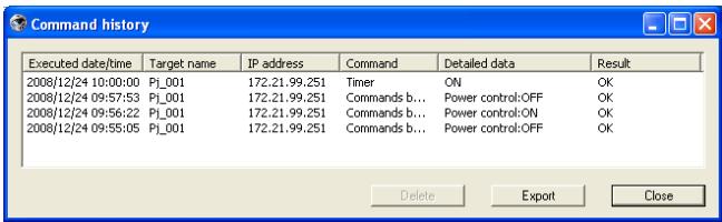
text_image
Command history Executed date/time Target name IP address Command Detailed data Result 2008/12/24 10:00:00 Pj_001 172.21.99.251 Timer ON OK 2008/12/24 09:57:53 Pj_001 172.21.99.251 Commands b... Power control:OFF OK 2008/12/24 09:56:22 Pj_001 172.21.99.251 Commands b... Power control:ON OK 2008/12/24 09:55:05 Pj_001 172.21.99.251 Commands b... Power control:OFF OK Delete Export CloseCommand history
Items Description
Executed date/time .... Executed date and time of the command
Target name...... Name of the network equipment
IP address......IP address of the network equipment
Command......Type of the Command
Detailed data..... Contents of the Command
Result ...... Results of the Command
0 The listed items are fixed.
0 Column width can be changed by dragging the right edge of the column. The column order can be changed with drag and drop the column. Column cannot be deleted.
0 Up to 1000 of events can be stored. If it exceeds 1000 events, the oldest event is deleted and the latest event is added.
Storing the management file
When you monitor the network equipment with the PJ Network Manager, you can save the registered target information, system setting and event log information into the management file with a free file name. It is useful if you manage multiple equipment in the network.
Click 📋 button on the tool bar and save it with free file name. The extension is ".pnm".
The management file contains following information.
| Items | Description |
| Header | Management file section, file version |
| System default setting | Default value of the system setting- Monitoring interval- Event reception process- Temperature unit- E-mail information |
| Target information | Information of the registered target- Target information (target name, IP address, Community, Introduction date)- target MIB information- Warning value set up |
| Event log information | Event log information (ALERT, TRAP, SYSERR) |
0 The maximum volume of a management file is required about 1MB. (Number of registrable targets is 200, number of events is 1000)
Information saved to the registry
Following application setting information is saved to the registry of your computer. So the setting condition is memorized even after quitting the application.
| Items | Description |
| Status window information...... | Display position and size of the status list window |
| Status list information...... | Display status column, column width and column order |
| Event log list information.... | Column width and order of the event log list |
| Font set up...... | Font setting value (Type face, size and style) |
Registering the target information from the defined file at once
The PJ Network Manager provides a function to import the target information from the defined file at once. Prepare the defined file (CSV data format) in which the target information is written along the format shown below.
1 Select Target batch registration from System menu. The target batch registration window appears.
2 Click Reference button and select a defined file to import the target information. The imported target information will be listed on the target batch registration window.
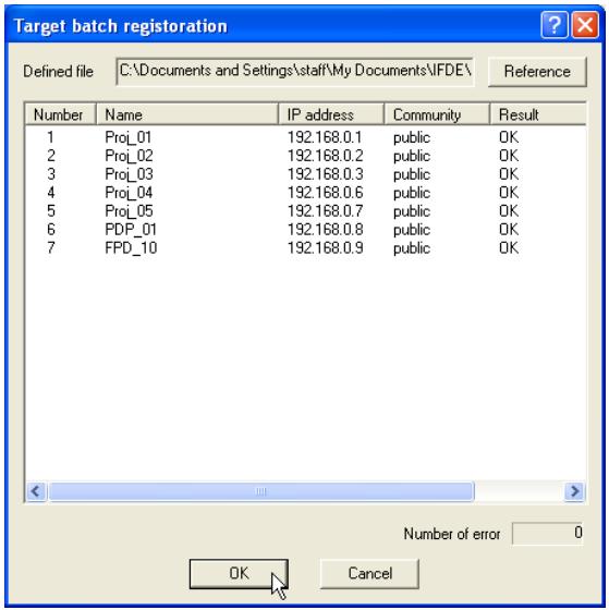
text_image
Target batch registration Defined file C:\Documents and Settings\staff\My Documents\IFDE\ Reference Number Name IP address Community Result 1 Proj_01 192.168.0.1 public OK 2 Proj_02 192.168.0.2 public OK 3 Proj_03 192.168.0.3 public OK 4 Proj_04 192.168.0.6 public OK 5 Proj_05 192.168.0.7 public OK 6 PDP_01 192.168.0.8 public OK 7 FPD_10 192.168.0.9 public OK Number of error 0 OK Cancel* If there is an error in the imported defined file, the error information will be indicated on the Result column. Retry importing after correcting the defined file.
3 Click OK button to execute the registration.
Format of the defined file
The defined file is a CSV data file created by the spreadsheet application and is defined as follows;
Column Description (example)
Target name.....Name of target equipment (Proj_01, Proj_03, PDP_01, etc.)
IP address ...... IP address (192.168.0.1, etc.)
Community ...... Name of SNMP community. Default value of our network products is "public"
Example of the defined file
The table below shows the example of the defined file provided with the target information. Save this file as the CSV file.
| Target name | IP address | Community |
| Proj_01 | 192.168.0.1 | public |
| Proj_02 | 192.168.0.2 | public |
| Proj_03 | 192.168.0.3 | public |
| Proj_04 | 192.168.0.6 | public |
| Proj_05 | 192.168.0.7 | public |
| PDP_01 | 192.168.0.8 | public |
| FPD_10 | 192.168.0.9 | public |
Login to the target equipment
After double clicking the target name on the status list, the computer launches web browser and displays the login window of the target equipment.
You can control and set up the projector remotely by using the web browser. For the further information of instruction, see the separated network owner's manual.
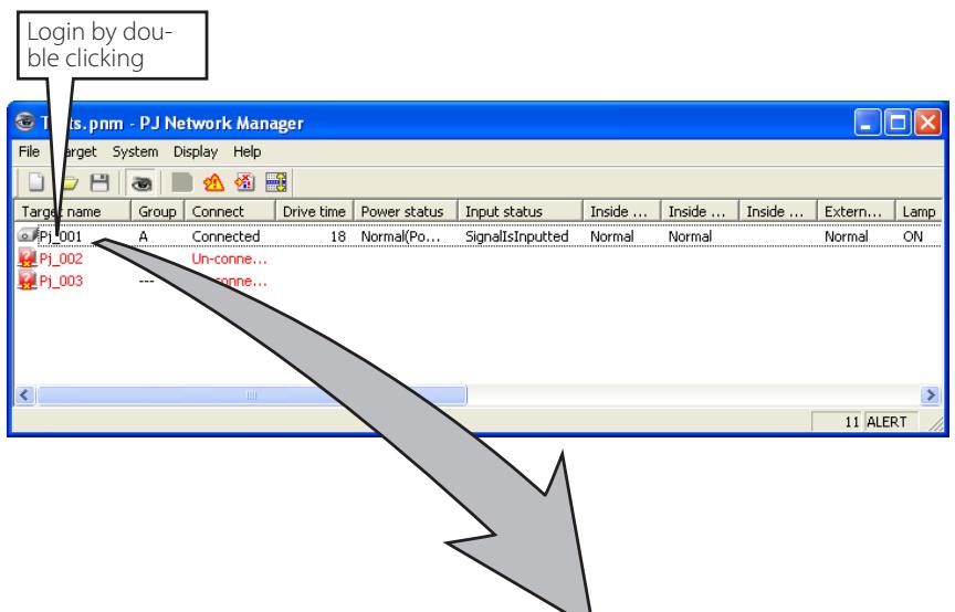
text_image
Login by double clicking PJs.pnm - PJ Network Manager File Target System Display Help Target name Group Connect Drive time Power status Input status Inside ... Inside ... Inside ... Extern... Lamp PJ_001 A Connected 18 Normal(Po... SignalsInputted Normal Normal Normal ON PJ_002 Un-conne... PJ_003 --- Un-conne... 11 ALERT0 An example of the login page.
text_image
Network - Microsoft Internet Explorer File Edit View Favorites Tools Help Back Search Favorites Go Links Address http://192.168.1.201/ Power & Status PJ status Power ON Status Normal Power control ON Standby Initial setting Power & Status PC Adj. Control Setting E-mail setting Network Information SNMP setting
natural_image
Illustration of three colorful birds perched on a green branch against a red background (no text or symbols)ViewSonic®