
IMPULSE 500P - Active speaker PEAVEY - Free user manual and instructions
Find the device manual for free IMPULSE 500P PEAVEY in PDF.
| Product Type | Active Loudspeaker |
| Brand | PEAVEY |
| Model | IMPULSE 500P |
| RMS Power | 500 W |
| Frequency Response | 45 Hz - 20 kHz |
| Nominal Impedance | 8 ohms |
| Dimensions (H x W x D) | 60 x 40 x 35 cm |
| Weight | 22 kg |
| Power Supply | 230 V / 50 Hz |
| Audio Inputs | XLR, 6.35mm Jack |
| Audio Outputs | XLR Link |
| Built-in Protection | Thermal limiter and anti-clipping |
| Enclosure Material | Reinforced Polypropylene |
| Protective Grille | Perforated Steel |
| Recommended Use | Sound reinforcement, music playback |
| Maintenance and Cleaning | Clean with a soft dry cloth |
| Safety | Do not open - risk of electric shock. Have maintenance performed by a qualified professional. |
| Spare Parts and Repairability | Contact PEAVEY after-sales service |
Frequently Asked Questions - IMPULSE 500P PEAVEY
User questions about IMPULSE 500P PEAVEY
0 question about this device. Answer the ones you know or ask your own.
Ask a new question about this device
Download the instructions for your Active speaker in PDF format for free! Find your manual IMPULSE 500P - PEAVEY and take your electronic device back in hand. On this page are published all the documents necessary for the use of your device. IMPULSE 500P by PEAVEY.
USER MANUAL IMPULSE 500P PEAVEY
Intended to alert the user to the presence of uninsulated “dangerous voltage” within the product’s enclosure that may be of sufficient magnitude to constitute a risk of electric shock to persons.

Intended to alert the user of the presence of important operating and maintenance (servicing) instructions in the literature accompanying the product.
CAUTION: Risk of electrical shock — DO NOT OPEN!
CAUTION: To reduce the risk of electric shock, do not remove cover. No user serviceable parts inside. Refer servicing to qualified service personnel.
WARNING: To prevent electrical shock or fire hazard, do not expose this appliance to rain or moisture. Before using this appliance, read the operating guide for further warnings.

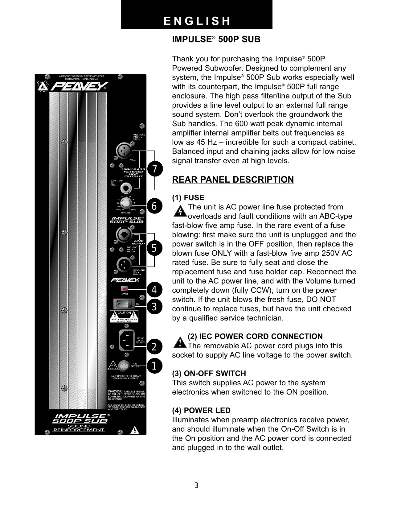
Thank you for purchasing the Impulse® 500P Powered Subwoofer. Designed to complement any system, the Impulse® 500P Sub works especially well with its counterpart, the Impulse® 500P full range enclosure. The high pass filter/line output of the Sub provides a line level output to an external full range sound system. Don't overlook the groundwork the Sub handles. The 600 watt peak dynamic internal amplifier internal amplifier belts out frequencies as low as 45 Hz – incredible for such a compact cabinet. Balanced input and chaining jacks allow for low noise signal transfer even at high levels.
REAR PANEL DESCRIPTION
(1) FUSE
The unit is AC power line fuse protected from overloads and fault conditions with an ABC-type fast-blow five amp fuse. In the rare event of a fuse blowing: first make sure the unit is unplugged and the power switch is in the OFF position, then replace the blown fuse ONLY with a fast-blow five amp 250V AC rated fuse. Be sure to fully seat and close the replacement fuse and fuse holder cap. Reconnect the unit to the AC power line, and with the Volume turned completely down (fully CCW), turn on the power switch. If the unit blows the fresh fuse, DO NOT continue to replace fuses, but have the unit checked by a qualified service technician.
▲ (2) IEC POWER CORD CONNECTION
The removable AC power cord plugs into this socket to supply AC line voltage to the power switch.
(3) ON-OFF SWITCH
This switch supplies AC power to the system electronics when switched to the ON position.
(4) POWER LED
Illuminates when preamp electronics receive power, and should illuminate when the On-Off Switch is in the On position and the AC power cord is connected and plugged in to the wall outlet.
(5) INPUTS
The input jacks are in parallel, to allow the audio input signal to be daisy-chained to other devices. The “output” level is the same as the “input” level and there is no isolation between the various jacks. The input is of the high impedance balanced type with high CMRR (excellent hum rejection). One input is a male XLR, and the other is a combo female XLR and 1/4" RTS connector.
(6) LEVEL
Controls the gain of the Impulse 500P Subwoofer. When used with the Input jacks (5), it is used to directly set the system output level. It does not affect the level of the signal coming out of the High Pass Filtered Output jacks. The high frequency levels can be set on that unit using its volume control.
(7) HIGH PASS FILTERED OUTPUTS
Provide a high pass filtered output to be fed to a powered full range enclosure, or what would nominally be a full range sound system, that is, a speaker system and a power amplifier. The output level is not controlled by the volume knob on the Impulse 500P Subwoofer, but should be set using the volume control on the separate powered enclosure used for the highs, or the power amplifier used to power the highs in the separate speaker enclosure.
OPERATING INSTRUCTIONS

CAUTIONS
The heat sink on the back plate can become hot to the touch. Do not block or cover the heat sink from ventilation.
When using the Impulse 500P Subwoofer with a stand, be sure to position one of the legs in the same direction as the rear of the system for maximum stability. Never use stands on unstable or tilted surfaces!
DO NOT connect the inputs of the Impulse 500P Subwoofer to the output of a power amplifier. The inputs are meant to be driven from a line level strength signal.
DO NOT remove the protective metal grille.
DO NOT use the INPUT jacks as mixers by trying to run more than one signal source at a time into them. The INPUT jacks (5) are all hard-wired together to allow use of any of the connector types as an input, and to allow a further send or “daisy-chaining” of the input signal to some other audio device (such as another Impulse 500P Subwoofer or other powered speaker). Attempting to run two different source signals directly into the Impulse 500P Subwoofer could damage the outputs of the source units. Use a mixer to combine two or more signals into a single signal sent to the Impulse 500P Subwoofer input.

WARNING: The Impulse 500P Subwoofer is extremely efficient and powerful! This sound system can permanently damage hearing! Use extreme care setting the overall mum loudness! The apparent sound level of the Impulse 500P Subwoofer can be
deceiving due to its clean sound output. The lack of distortion or obvious distress can make the sound level seem much lower than it actually is. This system is capable of SPL's in the bass range in excess of 120 dB at 1 M from the speaker!
USE OF THE IMPULSE 500P SUBWOOFER
GETTING AC POWER TO THE IMPULSE 500P SUBWOOFER
The Impulse 500P Subwoofer comes with an eight-foot IEC connection AC power cord. It is likely that some sort of extension cord will be used with this powered speaker system, so make sure that the extension cord is no longer than necessary, and is of a sufficient current capacity to maintain safety. Extension cords no longer than necessary and of the largest current capacity available will maximize the power output capability of the Impulse 500P Subwoofer's internal amplifiers. For best results, do not power anything else from the extension cord used to power the Impulse 500P Subwoofer, in order to minimize the voltage drop that all extension cords cause. Running one typical extension cord back to the wall plug for the entire sound system is not the way to maximize sound system performance.
USE OF A STAND
Use of a stand for the Impulse 500P Subwoofer is not necessary, and maximum bass output will occur when it is close to room boundaries such as a floor; however, there a some instances where stand mounting might be desired. The built-in stand adapter makes use of the Impulse 500P Subwoofer with a suitable stand easy, as long as it has a standard 1 3/8" diameter pole rated for at least 70 lbs. and has a minimum base equivalent to or broader than the Peavey S-1 stand. When using the Impulse 500P Subwoofer with a stand, be sure to position one of the legs in the same direction as the rear of the system for maximum stability. Peavey recommends the use of the Peavey S-1 stand for safety, should use of a stand be desired. Always secure the input cable with tape or a cable guard, and leave enough slack at the Impulse 500P Subwoofer input end to avoid anyone tripping over the cable or pulling the Impulse 500P Subwoofer over when stand mounted. Also, do not overextend the stand the Impulse 500P Subwoofer is mounted on.
GETTING A SIGNAL TO THE IMPULSE 500P Subwoofer
The Impulse 500P Subwoofer has a variety of ways to input a signal to the system. The balanced line level input(s) allows the use of a 1/4" phone plug, either a standard single-ended (tip-sleeve) plug, or a balanced RTS (ring-tip-sleeve) type plug OR either a male or female XLR plug.
While the standard single-ended 1/4" phone plug will work well, and the balanced input circuitry will provide some interference rejection, a balanced cable using either the balanced RTS 1/4" phone plug or the XLR plug will provide superior interference rejection and performance. Sometimes, with difficult interference problems, it will be helpful to lift the shield ground on a balanced cable at the Impulse 500P Subwoofer end only. Check any input changes carefully, always turning the volume control down before plugging and unplugging cables
Use of high-quality premium cables is recommended for the Impulse 500P Subwoofer, as these usually have better shielding and materials, and will provide greater long-term reliability.
It is usually a good idea to leave some slack at the input to the Impulse 500P Subwoofer and to also tape the cables down or run them under a cable guard to avoid anyone tripping over them or pulling the Impulse 500P over when stand mounted.
VOLUME CONTROL ADJUSTMENT
The Impulse 500P Subwoofer is equipped with a volume control to facilitate use in many different applications. With the volume control adjusted fully CW, gain is at maximum and the input sensitivity is 0.7 V RMS for full rated output. When driving the Impulse 500P Subwoofer from a mixer, it may be advantageous to reduce the input sensitivity by turning the volume control to the half-way point. The Impulse 500P Subwoofer will now more closely match a typical power amp input that the mixer operator is used to.
If the mixer board indicates clipping of its output signals, then all of the Impulse 500P Subwoofer power capability is not being utilized cleanly. Clipping the signal before it gets to the Impulse 500P Subwoofer is not optimal. In that case, reduce the mixer output level, and turn up the volume control on the Impulse 500P Subwoofer.
The amplifier in the Impulse 500P Subwoofer is equipped with DDT ^™ , however there is no indicator to show DDT ^™ has engaged. If the bass sound seems heavily compressed, then the Impulse 500P Subwoofer is heavily into DDT ^™ compression, and the drive level from the mixer (or the volume control on the Impulse 500P Subwoofer) needs to be reduced.
When first turning on the sound system, turn on all upstream electronics first, then the Impulse 500P Subwoofer with its volume control fully CCW (all the way down). If sending a signal to a full range powered system, such as the Impulse 500P, turn it on last, with its volume control fully CCW. Begin checking levels with the mixer output level controls all the way down, and bring them up slowly with the Impulse 500P Subwoofer volume control set to the desired setting (1/2 way up recommended to start).
HIGH PASS FILTERED OUTPUTS
These are low impedance filtered outputs that are provided to send the high frequencies to a powered speaker enclosure such as the Impulse® 500P full range system, or to a conventional power amp and speaker system. The output level is not affected by the volume control on the Impulse 500P Subwoofer.
The nominal polarity of these outputs is positive, and can be run directly into the Impulse 500P ^® for a nearly perfect mesh of the subwoofer with the full range unit. The polarity should also mesh with just about any other powered speaker or amplifier and speaker pair, as long as they observe industry standard polarities. In the event they do not, the balanced output can have pins two and three reversed with the use of an XLR or 1/4" phone cable that swaps these two pins at one end. This will reverse the polarity of the highs coming out of the high pass filtered output, and allow it to be used with equipment that might have polarity reversals.
USE OF MULTIPLE IMPULSE 500P SUBWOOFER'S
(or other Impulse ^® series powered products)
The provision of multiple parallel high-impedance inputs allows the inputs of the Impulse 500P Subwoofer to be “daisy-chained” from one to the other. Run the first cable from the
mixer to the first Impulse 500P Subwoofer, then hook a cable from one of the first Impulse 500P Subwoofer's inputs to the second Impulse 500P Subwoofer's input. This can be continued for several units, depending on how long the cables are, and the total capacitance of all the cables. With a low source impedance, such as a typical mixer output, and typical balanced cables, three or four Impulse 500P Subwoofer's can be daisy-chained from one output using 30- or 40- foot cables without obvious loss of high frequencies.
USE WITH IMPULSE 500P AND A MICROPHONE
When using the Impulse 500P Subwoofer with the Impulse 500P full range speaker system, and it is desired to use the Impulse 500P with a single microphone for karoke or PA announcements along with music, it is recommended that the microphone be connected directly to the Impulse 500P via the built-in mic input, instead of through a mixer microphone input and to the Impulse 500P Subwoofer's electronic crossover. While music will often benefit from the extra low end the subwoofer adds to the pairing, vocals do not maintain their clarity as well when additional bass output is added. By using the mic input on the Impulse 500P, the vocals in the mic will not get any additional bass boost, and the microphone input filtering will aid in maintaining vocal clarity. There is less tendency for very low frequency feedback, which could damage the powered subwoofer. See the Impulse 500P owner's manual, the Rear Panel Description, Mic Input portion, and the Use of the Impulse 500P section, the Use of the Mic Input with Simultaneous Music playback portion.
If the Impulse 500P Subwoofer is used as part of a full PA sound system, and multiple microphones are run into a mixer, and into the Impulse 500P Subwoofer, it might be helpful to make sure that the subwoofer's output is not set too high, so that the vocals are not made to sound too boomy or muddy. Avoiding bass boost on the mic channels, or even using a little bass cut on each mic might help avoid vocal boominess as well.
APPLICATIONS
The Impulse 500P Subwoofer has a variety of applications when used in conjunction with a full range system, such as sound reinforcement, or for musical playback. A typical signal source for the line level inputs (5) of the Impulse 500P would be a sound reinforcement mixing console (mixer), or the output from a CD player or tape deck.
TROUBLESHOOTING
No output at all:
First, make sure the unit has AC power and is turned on. If so, the Power LED (4) should be illuminated. If it is not, check that the On-Off switch (3) is in the “On” position, check the IEC power cord connection (2), making sure it is fully engaged and seated. Make sure the AC line cord is plugged into a working AC outlet, and last, check the fuse (1). (See the REAR PANEL/Fuse section for safety instructions.
Then, make sure that the inputs of the Impulse 500P Subwoofer are getting a signal by plugging the cable run into the Impulse 500P Subwoofer's inputs to some other device capable of determining this (for example, a power amp and speaker). If there is still no output, then be sure the volume control has been turned up to a reasonable level (1/3 to 1/2 way). Has the Impulse 500P Subwoofer been in direct sunlight or excessive heat? If so, it may have
triggered the thermal protection. Turn off the unit, and cool as best as the situation allows. (DO NOT use cold liquids for this purpose!) If there is still no output, it may help to read the owner's manual completely.
Hum or Buzz:
This can be AC outlet related, try plugging the Impulse 500P Subwoofer into a different AC outlet. Sometimes, if a different circuit (breaker) is used for the mixer and the Impulse 500P, it can cause hum problems. Check to make sure that shielded cables have been used to get the signal to the Impulse 500P's inputs. Speaker cables with 1/4" or XLR plugs will be very prone to hum.
Check to make sure light dimmers are not on the same circuit as the Impulse 500P or the mixer (or any source devices). If light dimmers are in use, then it may be necessary to turn them full on or full off to eliminate or reduce hum to tolerable levels. This is an AC wiring/light dimmer interference problem, and not the fault of the Impulse 500P Subwoofer.
Distorted or Fuzzy Sound:
First, make sure the mixer (or signal source) is not clipping or being overdriven. This can sometimes occur when the level control (6) on the Impulse 500P Subwoofer has been set too low (too far CCW), and it takes a lot of signal to drive the unit to full power.
Make sure the input plugs are fully seated in the input jacks (5) on the rear panel of the Impulse 500P Subwoofer.
Check to see that the proper inputs are being used (5), and not the high pass filter output (7), for line level input signals. Make sure that a power amp has not been plugged into the input jacks of the Impulse 500P Subwoofer.
If an extension cord is being used to provide the AC power to the unit, is it of sufficient current capacity and not also being used to supply power to any other units? See GETTING AC POWER TO THE IMPULSE 500P Subwoofer for details.
The Impulse 500P Subwoofer has built-in EQ to extend and smooth the natural response of the speaker in the system. Bass boost and infrasonic roll off have been applied, and the system has a nominally flat response, and should require little, if any, additional EQ. If excessive additional bass boost or EQ boost have been added externally to the Impulse 500P, it may cause premature overload at high SPL's. Try backing off of any external (mixer, rack Equalizer) EQ and see if that clears up any tendency to distort.
Finally, realize that even though the Impulse 500P Subwoofer is an extremely powerful and high output unit, it does ultimately have limits, and it may need additional powered units to provide enough sound output or coverage. In this case, try turning the mixer levels down a little to see if that clears things up.
If, after checking all the listed things to check, and anything else you can think of to check safely, and the system still exhibits problems, carefully note all conditions and check with your Peavey dealer for advice.
CARE and MAINTENANCE
Your Impulse 500P Subwoofer is a sturdy and durable product, which will provide years of reliable use if properly cared for. Use common sense and read the safety warnings to avoid hazardous operating conditions.
Sunlight/Heat
Avoid prolonged exposure to direct sunlight, as this may cause the unit to overheat and thermally shut off. Excessively hot operating conditions can also cause a thermal shutdown.
Do not store in extremely hot or cold conditions, or extremely high humidity. Always allow unit to come to room temperature before use.
Cleaning
Never clean the Impulse 500P Subwoofer while plugged in or turned on! When the unit has been fully disconnected from AC power sources, a slightly damp cloth can remove soil or other dirt. Never use strong solvents on the Impulse 500P Subwoofer, as they could attack the polymer that the cabinet is made from. Do not allow ANY fluids to drip inside the Impulse 500P Subwoofer!
Touchup
If the Impulse 500P Subwoofer cabinet should become scratched or abraded, it can be touched up using a black permanent marker. First, if the area to be touched up is larger than a short scratch, rub it lightly with an soapless plastic scrub pad. Wipe the scratched or abraded area a little at a time with the black permanent marker, and immediately wipe away the surplus with a lint-free cloth. For an overall finish enhancement and protective coating, use gloves to apply either WD-40 ^® or Armour All ^® protectant to the surface of the plastic cabinet only. Notice that the cabinet will be slippery after these treatments. Rub them down vigorously with a dry lint-free cloth to minimize this.
Insert Points (maximum depth of insertion)
The insert points on the top and bottom of the cabinet must only be engaged to a depth of 3/8" or less to prevent air leaks if the mounts/bolts are removed later.
Check for Secure Hardware
After a long period of use, check the hardware of the Impulse 500P Subwoofer for tightness, including the rear panel screws, and the screws that hold the baffle and rear cabinet together. The unit is subject to a great deal of vibration, and this could cause them to be less than tight with continued use.
DESCRIPTION
The Peavey Impulse 500P Subwoofer is a powered subwoofer engineered to provide the highest levels of performance in a compact powered loudspeaker. Capable of over 124 dB peak SPL's, this subwoofer can pump out a huge amount of bass. The enclosure utilizes high-impact polypropylene in an injection-molded plastic trapezoidal form, with a coated perforated metal grille to offer a cosmetically elegant yet durable powered subwoofer.
This powered subwoofer system is comprised of a 600W dynamic peak power amplifier driving a 15" Black Widow® woofer (1568) with a Kevlar™ impregnated cone.
Balanced inputs provided to the preamp/EQ electronics are one 1/4" RTS phone jack, one male XLR and one combo female XLR and 1/4" RTS phone jack, all connected in parallel. The power amplifier providing the amplification is a low-distortion unit providing 300W RMS into the nominal 8 ohm load of the woofer. The amplifier was selected for its reliability and superb bass punch. The amplifier features our patented DDT™ compression, which virtually eliminates audible power amplifier clipping.
Multiple molded-in handles provide ease of transport, while multiple mounting points (top and bottom) for the Peavey Versamount™ 70 and a molded-in stand adapter provide for maximum utility.
Armor All ^® is a registered trademark of The Clorox Company. WD-40 ^® is a registered trademark of WD-40 Company. Kevlar ^® is a registered trademark of DuPont.
IMPULSE® 500P SUB SPECIFICATIONS
Enclosure:
Peavey Impulse® 500P Subwoofer (domestic)
Frequency Response:
45 Hz to 150 Hz
Low Frequency Limit (-3 dB point):
45 Hz
Useable Low Frequency Limit (-10 dB point):
36 Hz
Internal Power Amplifiers (@120 VAC line):
600 watts peak dynamic power, 300 watts continuous RMS at clipping
Nominal Sensitivity (2.83V @ 1M, swept sine input in anechoic environment):
98 dB
Maximum Sound Pressure Level:
124 dB music peak
Transducer Compliment:
Model 1568 15" Black Widow® weather-resistant woofer
Box Tuning Frequency (Fbox):
44 Hz
Electrical Crossover Frequency (High Pass Output):
150 Hz
Crossover Type:
Internal electronic two-way crossover with active bass boost and subsonic filtering
Crossover Slopes:
18 dB/octave (3rd order) low pass, 18 dB/octave (3rd order) high pass, staggered poles
Electronic Input Impedance (Nominal):
Greater than 50 kohms, balanced or unbalanced
Input Connections:
One combo female XLR/ 1/4" phone jack and one male XLR and one 1/4" phone jack connector all providing balanced operation, in parallel
Enclosure Materials and Finish:
Injection-molded high-impact polypropylene of a nominal thickness of 1/4" and with textured finish, having a UL flame-rating
Mounting:
Stand mounting on 1 3/8" diameter stands via molded-in mount, flying via Peavey Versamount™ 70 (top or bottom of cabinet) and four rubber feet for floor use
Dimensions:
28.562" (72.55 cm) tall by 21.312" (54.13 cm) wide (11.5" {29.21 cm} wide in rear) by 17" (43.18 cm) deep
Optional Accessories:
Impulse® 500 Stacking Adapter Impulse® 500 Array Bracket
Net Weight:
62 lbs.
Shipping Weight:
72 lbs.
Additional Remarks:
Also available as a passive unit Impulse ^® 500 Subwoofer, 4 ohm
AMPLIFIER SPECIFICATIONS
Nominal Amplifier Frequency Response:
+0, -1 dB 10 Hz to 30 kHz
THD and IM:
Typically less than 0.2 %
Damping Factor:
Greater than 100 @ 1000 Hz, 8 ohms
Hum and Noise:
Greater than 95 dB below rated power
DDT Dynamic Range:
Greater than 26 dB
Power requirements of Impulse® 500P Subwoofer
System (domestic):
500 watts, 120VAC, 60 Hz
Architectural and Engineering Specifications
The powered loudspeaker system shall have a frequency response from 45 Hz to 150 Hz. The peak SPL with inaudible distortion shall reach 124 dB with music as a source, when measured at a distance of 1M and driven to full output capacity. The system shall utilize a 15" Black Widow ^® woofer.
The powered subwoofer system shall have a group of high impedance input connectors consisting of one 1/4" RTS phone jack, one male XLR and one combo female XLR and 1/4" RTS phone jack, on the rear panel, all connected in parallel. A volume control will be located next to the input jack group. A balanced high pass filtered output shall be provided, with one female XLR and one 1/4" RTS phone jack provided.
The system power amplifiers shall have an unfiltered frequency response of 10 Hz to 30 kHz which deviates no more than +0, -1 dB up to rated power, a damping factor greater than 100 @ 1 kHz into 8 ohms, hum and noise better than 95 dB below rated power, and typical THD and IMD of less than 0.2%. The amplifier shall be capable of 300W into an 8 ohm nominal load, and shall incorporate DDT ^™ compression.
The input signal shall be electronically divided into high frequencies and low frequencies by a staggered pole third order slope line level crossover at 150 Hz. The low frequencies shall be processed to provide bass boost, subsonic filtering and overall response shaping, and the high frequencies shall be made available via an external output.
The enclosure shall be constructed of injection-molded polypropylene of 1/4" nominal thickness with a UL flame rating, and reinforcing ribs internally. A handgrip shall be molded in on each side of the woofer and on the top rear edge.
A vinyl coated perforated metal grille shall be provided for woofer protection. The cabinet shall incorporate four tall sturdy rubber feet for floor standing use, and four mounting point inserts on the top and bottom each for flying use.
The outside dimensions shall be 28 9/16" tall by 21 5/16" wide by 17" deep, and the weight shall be 62 lbs. Power requirements shall be: 500 watts, 120VAC, 60 Hz Domestic and 240 VAC, 50 Hz (European). The loudspeaker system shall be called a Peavey Impulse 500P Subwoofer.
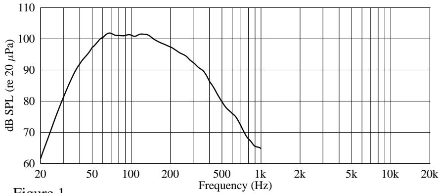
Amplitude Response (1W 1m On-Axis)
line
| Frequency (Hz) | dB SPL (re 20 μPa) | | -------------- | ------------------ | | 20 | 60 | | 50 | 95 | | 100 | 100 | | 200 | 98 | | 500 | 85 | | 1k | 65 |Figure 1
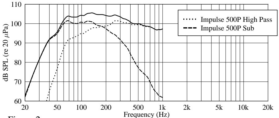
Amplitude Response (1W 1m On-Axis)
line
| Frequency (Hz) | Impulse 500P High Pass | Impulse 500P Sub | | -------------- | ---------------------- | ---------------- | | 20 | 60 | 60 | | 50 | 95 | 95 | | 100 | 102 | 101 | | 200 | 103 | 100 | | 500 | 101 | 98 | | 1k | 97 | 62 |Figure 2
Harmonic Distortion at 100 dB
line
| Frequency (Hz) | dB SPL (re 20 µPa) | | -------------- | ------------------ | | 20 | 60 | | 50 | 90 | | 100 | 100 | | 200 | 95 | | 500 | 80 | | 1k | 65 |Figure 3
…… 2nd Harmonic
--- 3rd Harmonic
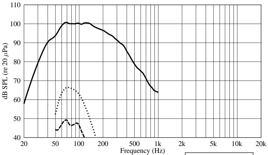
Harmonic Distortion at 110 dB
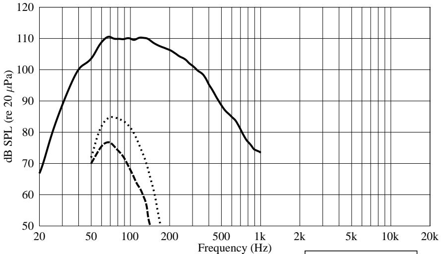
line
| Frequency (Hz) | dB SPL (re 20 µPa) | | -------------- | ------------------ | | 20 | 68 | | 50 | 102 | | 75 | 110 | | 100 | 110 | | 150 | 108 | | 200 | 105 | | 500 | 95 | | 1k | 74 |Figure 4
…… 2nd Harmonic
--- 3rd Harmonic
SUB IMPULSE® 500P SUBWOOFER
Complemento Transductor:
Woofer Modelo 1568 de 15" Black Widow® resistente a
cambios climáticos
IMPORTANT SAFETY INSTRUCTIONS
WARNING: When using electric products, basic cautions should always be followed, including the following:
- Read these instructions.
- Keep these instructions.
- Heed all warnings.
- Follow all instructions.
- Do not use this apparatus near water. For example, near or in a bathtub, swimming pool, sink, wet basement, etc.
- Clean only with a damp cloth.
- Do not block any of the ventilation openings. Install in accordance with manufacturer's instructions. It should not be placed flat against a wall or placed in a built-in enclosure that will impede the flow of cooling air.
- Do not install near any heat sources such as radiators, heat registers, stoves or other apparatus (including amplifiers) that produce heat.
- Do not defeat the safety purpose of the polarized or grounding-type plug. A polarized plug has two blades with one wider than the other. A grounding type plug has two blades and a third grounding plug. The wide blade or third prong is provided for your safety. When the provided plug does not fit into your inlet, consult an electrician for replacement of the obsolete outlet. Never break off the grounding. Write for our free booklet “Shock Hazard and Grounding”. Connect only to a power supply of the type marked on the unit adjacent to the power supply cord.
- Protect the power cord from being walked on or pinched, particularly at plugs, convenience receptacles, and the point they exit from the apparatus.
- Only use attachments/accessories provided by the manufacturer.
- Use only with a cart, stand, tripod, bracket, or table specified by the manufacturer, or sold with the apparatus. When a cart is used, use caution when moving the cart/apparatus combination to avoid injury from tip-over.
- Unplug this apparatus during lightning storms or when unused for long periods of time.
- Refer all servicing to qualified service personnel. Servicing is required when the apparatus has been damaged in any way, such as power-supply cord or plug is damaged, liquid has been spilled or objects have fallen into the apparatus, the apparatus has been exposed to rain or moisture, does not operate normally, or has been dropped.
- If this product is to be mounted in an equipment rack, rear support should be provided.
- Exposure to extremely high noise levels may cause a permanent hearing loss. Individuals vary considerably in susceptibility to noise-induced hearing loss, but nearly everyone will lose some hearing if exposed to sufficiently intense noise for a sufficient time.
The U.S. Government's Occupational and Health Administration (OSHA) has specified the following permissible noise level exposures:
| Duration Per Day In Hours | Sound Level dBA, Slow Response |
| 8 | 90 |
| 6 | 92 |
| 4 | 95 |
| 3 | 97 |
| 2 | 100 |
| 1 1/2 | 102 |
| 1 | 105 |
| 1/2 | 110 |
| 1/4 or less | 115 |
According to OSHA, any exposure in excess of the above permissible limits could result in some hearing loss. Ear plugs or protectors to the ear canals or over the ears must be worn when operating this amplification system in order to prevent a permanent hearing loss, if exposure is in excess of the limits as set forth above. To ensure against potentially dangerous exposure to high sound pressure levels, it is recommended that all persons exposed to equipment capable of producing high sound pressure levels such as this amplification system be protected by hearing protectors while this unit is in operation.
SAVE THESE INSTRUCTIONS!
PEAVEY ELECTRONICS CORPORATION LIMITED WARRANTY
Effective Date: July 1, 1998
What This Warranty Covers
Your Peavey Warranty covers defects in material and workmanship in Peavey products purchased and serviced in the U.S.A. and Canada.
What This Warranty Does Not Cover
The Warranty does not cover: (1) damage caused by accident, misuse, abuse, improper installation or operation, rental, product modification or neglect; (2) damage occurring during shipment; (3) damage caused by repair or service performed by persons not authorized by Peavey; (4) products on which the serial number has been altered, defaced or removed; (5) products not purchased from an Authorized Peavey Dealer.
Who This Warranty Protects
This Warranty protects only the original retail purchaser of the product.
How Long This Warranty Lasts
The Warranty begins on the date of purchase by the original retail purchaser. The duration of the Warranty is as follows:
| Product Category | Duration |
| Guitars/Basses, Amplifiers, Pre-Amplifiers, Mixers, Electronic Crossovers and Equalizers | 2 years *(+ 3 years) |
| Drums | 2 years *(+ 1 year) |
| Enclosures | 3 years *(+ 2 years) |
| Digital Effect Devices and Keyboard and MIDI Controllers | 1 year *(+ 1 year) |
| Microphones | 2 years |
| Speaker Components (incl. speakers, baskets, drivers, diaphragm replacement kits and passive crossovers) and all Accessories | 1 year |
| Tubes and Meters | 90 days |
[*denotes additional warranty period applicable if optional Warranty Registration Card is completed and returned to Peavey by original retail purchaser within 90 days of purchase.]
What Peavey Will Do
We will repair or replace (at Peavey's discretion) products covered by warranty at no charge for labor or materials. If the product or component must be shipped to Peavey for warranty service, the consumer must pay initial shipping charges. If the repairs are covered by warranty, Peavey will pay the return shipping charges.
How To Get Warranty Service
(1) Take the defective item and your sales receipt or other proof of date of purchase to your Authorized Peavey Dealer or Authorized Peavey Service Center.
OR
(2) Ship the defective item, prepaid, to Peavey Electronics Corporation, International Service Center, 412 Highway 11 & 80 East, Meridian, MS 39301 or Peavey Canada Ltd., 95 Shields Court, Markham, Ontario, Canada L3R 9T5. Include a detailed description of the problem, together with a copy of your sales receipt or other proof of date of purchase as evidence of warranty coverage. Also provide a complete return address.
Limitation of Implied Warranties
ANY IMPLIED WARRANTIES, INCLUDING WARRANTIES OF MERCHANTABILITY AND FITNESS FOR A PARTICULAR PURPOSE, ARE LIMITED IN DURATION TO THE LENGTH OF THIS WARRANTY.
Some states do not allow limitations on how long an implied warranty lasts, so the above limitation may not apply to you.
Exclusions of Damages
PEAVEY'S LIABILITY FOR ANY DEFECTIVE PRODUCT IS LIMITED TO THE REPAIR OR REPLACEMENT OF THE PRODUCT, AT PEAVEY'S OPTION. IF WE ELECT TO REPLACE THE PRODUCT, THE REPLACEMENT MAY BE A RECONDITIONED UNIT. PEAVEY SHALL NOT BE LIABLE FOR DAMAGES BASED ON INCONVENIENCE, LOSS OF USE, LOST PROFITS, LOST SAVINGS, DAMAGE TO ANY OTHER EQUIPMENT OR OTHER ITEMS AT THE SITE OF USE, OR ANY OTHER DAMAGES WHETHER INCIDENTAL, CONSEQUENTIAL OR OTHERWISE, EVEN IF PEAVEY HAS BEEN ADVISED OF THE POSSIBILITY OF SUCH DAMAGES.
Some states do not allow the exclusion or limitation of incidental or consequential damages, so the above limitation or exclusion may not apply to you.
This Warranty gives you specific legal rights, and you may also have other rights which vary from state to state.
If you have any questions about this warranty or service received or if you need assistance in locating an Authorized Service Center, please contact the Peavey International Service Center at (601) 483-5365 / Peavey Canada Ltd. at (905) 475-2578.
Features and specifications subject to change without notice.
Features and specifications subject to change without notice.
Peavey Electronics Corporation • 711 A Street • Meridian • MS • 39301
(601) 483-5365 • FAX (601) 486-1278 • www.peavey.com
- REAR PANEL DESCRIPTION
- FUSE
- ▲ (2) IEC POWER CORD CONNECTION
- ON-OFF SWITCH
- POWER LED
- INPUTS
- LEVEL
- HIGH PASS FILTERED OUTPUTS
- OPERATING INSTRUCTIONS
- CAUTIONS
- USE OF THE IMPULSE 500P SUBWOOFER
- GETTING AC POWER TO THE IMPULSE 500P SUBWOOFER
- USE OF A STAND
- GETTING A SIGNAL TO THE IMPULSE 500P Subwoofer
- VOLUME CONTROL ADJUSTMENT
- HIGH PASS FILTERED OUTPUTS
- USE OF MULTIPLE IMPULSE 500P SUBWOOFER'S
- USE WITH IMPULSE 500P AND A MICROPHONE
- APPLICATIONS
- TROUBLESHOOTING
- No output at all:
- Hum or Buzz:
- Distorted or Fuzzy Sound:
- CARE and MAINTENANCE
- Sunlight/Heat
- Cleaning
- Touchup
- Insert Points (maximum depth of insertion)
- Check for Secure Hardware
- DESCRIPTION
- IMPULSE® 500P SUB SPECIFICATIONS
- Enclosure:
- Frequency Response:
- Low Frequency Limit (-3 dB point):
- Useable Low Frequency Limit (-10 dB point):
- Internal Power Amplifiers (@120 VAC line):
- Nominal Sensitivity (2.83V @ 1M, swept sine input in anechoic environment):
- Maximum Sound Pressure Level:
- Transducer Compliment:
- Box Tuning Frequency (Fbox):
- Electrical Crossover Frequency (High Pass Output):
- Crossover Type:
- Crossover Slopes:
- Electronic Input Impedance (Nominal):
- Input Connections:
- Enclosure Materials and Finish:
- Mounting:
- Dimensions:
- Optional Accessories:
- Net Weight:
- Shipping Weight:
- Additional Remarks:
- AMPLIFIER SPECIFICATIONS
- Nominal Amplifier Frequency Response:
- THD and IM:
- Damping Factor:
- Hum and Noise:
- DDT Dynamic Range:
- Power requirements of Impulse® 500P Subwoofer
- System (domestic):
- Architectural and Engineering Specifications
- SUB IMPULSE® 500P SUBWOOFER
- Complemento Transductor:
- IMPORTANT SAFETY INSTRUCTIONS
- SAVE THESE INSTRUCTIONS!
- PEAVEY ELECTRONICS CORPORATION LIMITED WARRANTY
- Effective Date: July 1, 1998
- What This Warranty Covers
- What This Warranty Does Not Cover
- Who This Warranty Protects
- How Long This Warranty Lasts
- What Peavey Will Do
- How To Get Warranty Service
- OR
- Limitation of Implied Warranties
- Exclusions of Damages
Brand : PEAVEY
Model : IMPULSE 500P
Category : Active speaker