
M-164FX - Mixer TASCAM - Free user manual and instructions
Find the device manual for free M-164FX TASCAM in PDF.
| Brand | TASCAM |
| Model | M-164FX |
| Product type | Analog mixing console with digital effects |
| Number of channels | 16 (8 mono + 4 stereo) |
| Built-in effects processor | Yes, 16 digital presets |
| Equalization | 3-band per channel (HF, MF, LF) |
| Microphone inputs | 8 XLR inputs with +48V phantom power |
| Line inputs | 8 TRS 6.35 mm jack inputs |
| Main outputs | 2 XLR outputs (Main L/R) + 2 TRS jack outputs |
| Auxiliary outputs | 3 auxiliary sends (Pre/Post) |
| Headphone output | Stereo 6.35 mm jack with dedicated volume |
| Power supply | Mains 230V~50Hz, external adapter |
| Power consumption | 30 W maximum |
| Dimensions (W × D × H) | Approx. 438 × 348 × 105 mm |
| Weight | Approx. 5.2 kg |
| Chassis material | Metal and ABS plastic |
| Operating temperature | 5°C to 35°C |
| Operating humidity | 30% to 85% (non-condensing) |
| Maintenance and cleaning | Dust with a soft, dry cloth. Do not use solvents. |
| Safety | Do not expose to moisture or heat sources. Unplug before cleaning. |
| Spare parts and repairability | Contact an authorized TASCAM after-sales service. |
| General information | User manual available for free download in PDF format. |
Frequently Asked Questions - M-164FX TASCAM
User questions about M-164FX TASCAM
0 question about this device. Answer the ones you know or ask your own.
Ask a new question about this device
Download the instructions for your Mixer in PDF format for free! Find your manual M-164FX - TASCAM and take your electronic device back in hand. On this page are published all the documents necessary for the use of your device. M-164FX by TASCAM.
USER MANUAL M-164FX TASCAM
| CAUTION: TO REDUCE THE RISK OF ELECTRIC SHOCK, DO NOT REMOVE COVER (OR BACK). NO USER-SERVICEABLE PARTS INSIDE. REFER SERVICING TO QUALIFIED SERVICE PERSONNEL. | |
 | The lightning flash with arrowhead symbol, within equilateral triangle, is intended to alert the user to the presence of uninsulated “dangerous voltage” within the product’s enclosure that may be of sufficient magnitude to constitute a risk of electric shock to persons. |
 | The exclamation point within an equilateral triangle is intended to alert the user to the presence of important operating and maintenance (servicing) instructions in the literature accompanying the appliance. |
For U.S.A.
TO THE USER
This equipment has been tested and found to comply with the limits for a Class A digital device, pursuant to Part 15 of the FCC Rules. These limits are designed to provide reasonable protection against harmful interference when the equipment is operated in a commercial environment. This equipment generates, uses, and can radiate radio frequency energy and, if not installed and used in accordance with the instruction manual, may cause harmful interference to radio communications.
Operation of this equipment in a residential area is likely to cause harmful interference in which case the user will be required to correct the interference at his own expense.
CAUTION
Changes or modifications to this equipment not expressly approved by TEAC CORPORATION for compliance could void the user's authority to operate this equipment.
CE Marking Information
a) Applicable electromagnetic environment: E4
b) Peak inrush current: 4.3 A
WARNING: TO PREVENT FIRE OR SHOCK HAZARD, DO NOT EXPOSE THIS APPLIANCE TO RAIN OR MOISTURE.
For the customers in Europe
WARNING
This is a Class A product. In a domestic environment, this product may cause radio interference in which case the user may be required to take adequate measures.
IMPORTANT SAFETY INSTRUCTIONS
1 Read these instructions.
2 Keep these instructions.
3 Heed all warnings.
4 Follow all instructions.
5 Do not use this apparatus near water.
6 Clean only with dry cloth.
7 Do not block any ventilation openings. Install in accordance with the manufacturer's instructions.
8 Do not install near any heat sources such as radiators, heat registers, stoves, or other apparatus (including amplifiers) that produce heat.
9 Do not defeat the safety purpose of the polarized or grounding-type plug. A polarized plug has two blades with one wider than the other. A grounding type plug has two blades and a third grounding prong. The wide blade or the third prong are provided for your safety. If the provided plug does not fit into your outlet, consult an electrician for replacement of the obsolete outlet.
10 Protect the power cord from being walked on or pinched particularly at plugs, convenience receptacles, and the point where they exit from the apparatus.
11 Only use attachments/accessories specified by the manufacturer.
12 Use only with the cart, stand, tripod, bracket, or table specified by the manufacturer, or sold with the apparatus. When a cart is used, use caution when moving the cart/apparatus combination to avoid injury from tip-over.
natural_image
Symbolic icon of a person lifting a large object inside a circle (no text or symbols)13 Unplug this apparatus during lightning storms or when unused for long periods of time.
14 Refer all servicing to qualified service personnel. Servicing is required when the apparatus has been damaged in any way, such as power-supply cord or plug is damaged, liquid has been spilled or objects have fallen into the apparatus, the apparatus has been exposed to rain or moisture, does not operate normally, or has been dropped.
- Do not expose this apparatus to drips or splashes.
- Do not place any objects filled with liquids, such as vases, on the apparatus.
- Do not install this apparatus in a confined space such as a book case or similar unit.
- The apparatus draws nominal non-operating power from the AC outlet with its POWER or STANDBY/ON switch not in the ON position.
- The apparatus should be located close enough to the AC outlet so that you can easily grasp the power cord plug at any time.
- The mains plug is used as the disconnect device, the disconnect device shall remain readily operable.
- Products with Class I construction are equipped with a power supply cord that has a 3-prong grounding plug. The cord of such a product must be plugged into an AC outlet that has a protective grounding connection.
- If the product uses batteries (including a battery pack or installed batteries), they should not be exposed to sunshine, fire or excessive heat.
- CAUTION for products that use replaceable lithium batteries: there is danger of explosion if a battery is replaced with an incorrect type of battery. Replace only with the same or equivalent type.
- Caution should be taken when using earphones or headphones with the product because excessive sound pressure (volume) from earphones or headphones can cause hearing loss.
- Use the included AC adaptor (TASCAM PS-1225L) and power cord set with this equipment. Use of any other power source could cause malfunction, fire or electrical shock.
- Do not use the included AC adaptor (TASCAM PS-1225L) and power cord set with other equipment. Doing so could cause malfunction, fire or electrical shock.
1 - Introduction ...... 5
Main features....5
Included items....5
About this manual 5
Trademarks....6
Precautions and notes for placement and use....6
Cleaning the unit 6
2 – Names and Functions of Parts ...... 7
Top panel....7
Rear panel 10
3 – Preparation for Use...... 12
Connecting the power 12
Examples of connecting external equipment 12
Making stereo output connections.... 15
Connecting headphones 15
Making input sound source connections .... 15
Connecting mics 15
Connecting synthesizers, other sound sources and audio equipment (line level sound sources) 16
Setting the internal effects return channels (M-164FX and M-164UF)...... 16
Turning the power on and putting the mixer in standby.... 17
Before turning the power on.... 17
Turning on the power 17
Putting the mixer in standby 17
4 – Using the mixer...... 18
Adjusting levels.... 18
Using the mixer channel functions...... 19
High-pass filter (HPF) 19
EQ....19
AUX sends 20
Pan And Balance 21
Bus assignments 21
Monitoring with headphones...... 21
Using AUX 1 for a monitoring mix ...... 21
Using sub-group functions.... 22
Using the internal effects (M-164FX and M-164UF) 23
Using external effects 24
Using a record player....25
Making final adjustments to the main output sound 25
5 – Using with a Computer (M-164UF) 26
Functions 26
Installation 26
System requirements.... 26
Installing the drivers.... 26
How to update the firmware....29
Computer settings 29
Control panel settings 30
Overview 30
Driver settings 30
Connecting by USB 30
Using Cubase LE4 to record 30
6 – Troubleshooting......31
Related to mixer settings 31
Related to recording with Cubase LE4
(M-164UF ONLY) 31
7 – Specifications and Block Diagrams ... 32
Ratings....32
Inputs....32
Outputs 32
Performance....33
Other 33
Dimensional drawing....34
Block diagram 35
Level diagram....36
This appliance has a serial number located on the rear panel. Please record the model number and serial number and retain them for your records.
Model number
Serial number ____
Thank you very much for purchasing this TASCAM M-164 series mixer.
Before using the unit, please read this Owner's Manual carefully so that you will understand the correct operating procedures. We hope that you will enjoy using this product for many years to come.
Please keep this manual for future reference. You can also download a digital copy of this Owner's Manual from our website (http://www.tascam.com/).
Main features
- Audio mixer with 16 inputs, 4 output busses and 2 AUX sends
- All input channels have faders and the stereo (ST) and SUB buses have output faders
- Meter bridge allows observation of input and monitor levels
- Channels 1–6 are mic/line input channels that have both XLR mic input connectors with +48V phantom power, standard jacks for line inputs and a full set of mixer functions (TRIM, HPF, 3-band EQ, 2 AUX sends, PAN, fader and bus assign switch)
- Channels 7–10 are stereo line input channels with numerous mixer functions (2-band EQ, 2 AUX sends, PAN, fader and bus assign switch)
- Channels 9-10 include a PHONO input preamp, allowing direct connection of a record player
- Channels 11-12, 13-14 and 15-16, which are 3 pairs of stereo line input channels with faders and bus assign switches, have adjustable levels and can be used as sub-inputs
- On M-164FX and M-164UF mixers, channels 13-14 or 15-16 can be used as return channels for the internal effects
- On M-164UF mixers, audio signals from a computer can be input to channels 11-12 by USB
- TO AUX 1 switches are included on M-164 channels 13-14, M-164FX channels 13-14 and 15-16 and on M-164UF channels 11-12, 13-14 and 15-16
- SUB and main stereo (ST) output busses each have dedicated faders, allowing independent adjustment of output levels
- TO ST switch on SUB bus can be turned ON to send its signal to the stereo output, allowing the SUB bus to be used as a sub-mix group
- Channel 1-10 AUX sends can be used to send input signals to the internal effects or monitoring outputs
-
AUX 1 has a PRE switch allowing pre/post selection (AUX 2 is fixed to post)
-
AUX MASTER (1, 2) knobs adjust the total AUX 1 and 2 send levels
- Bus assign switches on all input channels
- Internal digital effects on M-164FX and M-164UF mixers
- 2-band EQ on the stereo bus to control the sound quality of the mixed stereo output
- Stereo and mono output jacks for both stereo and SUB bus outputs
- Headphone monitoring of stereo, SUB or AUX 1 bus possible
- M-164UF has USB 2.0 audio interface that allows 16 channels to be sent to (inputs 1–10, AUX send 1/2, SUB bus, stereo bus) and 2 channels to be returned from a computer
Included items
The included items are listed below.
Take care when opening the package not to damage the items. Keep the package materials for transportation in the future.
Please contact the store where you purchased this unit if any of these items are missing or have been damaged during transportation.
- Main unit .... 1
- AC adaptor (TASCAM PS-1225L) .... 1
- USB cable (M-164UF only)....1
- CD-ROM (Driver, M-164UF only) .... 1
• DVD-ROM (Cubase LE4, M-164UF only)......1 - Cubase LE4 Quick Start Guide (Driver, M-164UF only)....1
- A warranty card ....1
- Owner's manual (this manual) ....1
CAUTION
Always use the included TASCAM PS-1225L (AC adaptor/power cord) with this equipment. Do not use the included AC adaptor and power cord set with other equipment. Doing so could cause malfunction, fire or electrical shock.
About this manual
In this manual, we use the following conventions:
- The names of keys and controls are given in the following typeface: MENU.
- Additional information is introduced in the styles below when needed:
TIP
Useful hints when using the unit.
1 - Introduction
NOTE
Explanation of actions in special situation and supplement.
CAUTION
Instructions that should be followed to avoid injury, damage to the unit or other equipment, and loss of data.
Trademarks
- TASCAM is a registered trademark of TEAC Corporation.
- Microsoft and Windows are either registered trademarks or trademarks of Microsoft Corporation in the United States and/or other countries.
- Macintosh, Mac OS and Mac OS X are trademarks of Apple Inc.
- Pentium is a trademark of Intel Corporation in the U.S. and other countries.
- AMD Athlon is a trademark of Advanced Micro Devices, Inc.
- iPod is a trademark of Apple Inc.
- Other company names, product names and logos in this document are the trademarks or registered trademarks of their respective owners.
Precautions and notes for placement and use
- Use this product within its guaranteed operating temperature range of 5–35°C. In addition, avoid placement in dusty or humid locations because such conditions could cause malfunction.
- Do not apply strong force to this unit. Doing so could damage the internal circuitry or external panels.
- Do not use near anything that generates a strong magnetic field. Doing so could cause hum or high frequency interference, for example.
Cleaning the unit
To clean the unit, wipe it gently with a soft cloth slightly dampened with a diluted neutral cleanser. Do not wipe with chemical cleaning cloths, benzine, paint thinner, or other chemical agents as they could damage the surface.
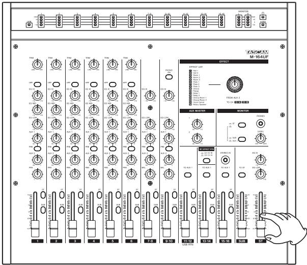
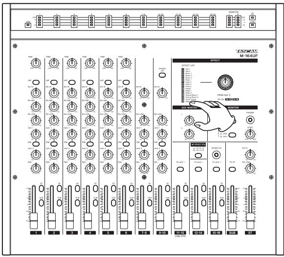
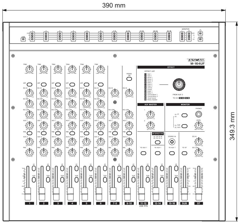
Top panel
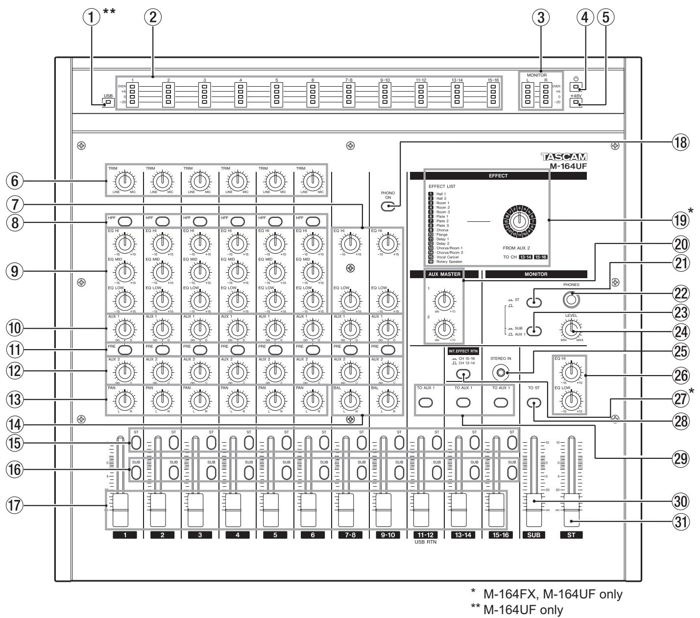
①\*\*USB indicator
Lights when the mixer is connected to a computer by USB.
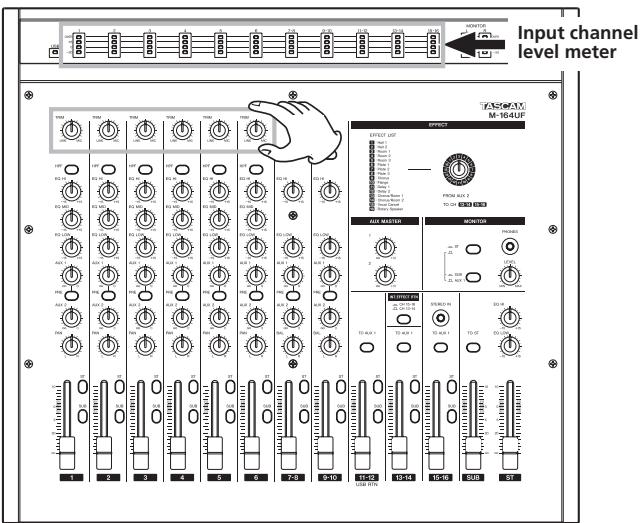
② Input channel meters
Display the input level of each input channel (levels after signals pass through the EQ section).
③ MONITOR (L, R) meters
Display the output signal level of the monitoring source (stereo, SUB or AUX 1 bus) that has been selected with the two switches at the MONITOR section.
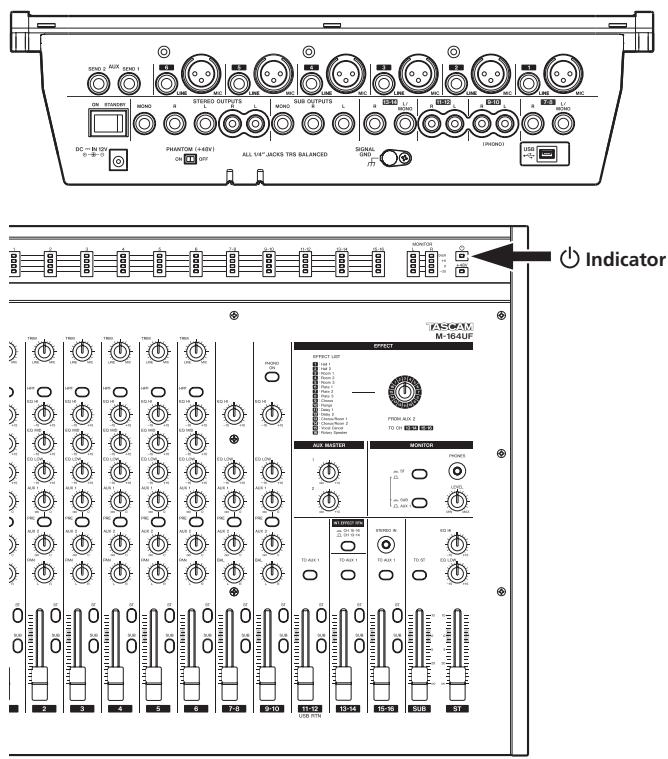
④ ⏻ indicator
Lights when the mixer power has been turned ON using the ON/STANDBY switch on the rear panel.
⑤ +48V indicator
Lights when the phantom power has been turned ON using the PHANTOM (+48V) switch on the rear panel.
⑥ TRIM knobs (channels 1–6)
Use to adjust the input levels of signals from the MIC and LINE input jacks. While observing the channel meters above, turn to the left (toward LINE) for line level sources (electronic instruments, audio equipment, etc.) or to the right (toward MIC) for microphones.
⑦ EQ section (channels 7-8, 9-10)
These channels each have a 2-band EQ.
The EQ HI knob adjusts the high frequency range with a roll-off frequency of 12 kHz and a boost/cut range of ±15 dB.
The EQ LOW knob adjusts the low frequency range with a roll-off frequency of 100 Hz and a boost/cut range of ±15 dB.
2 - Names and Functions of Parts
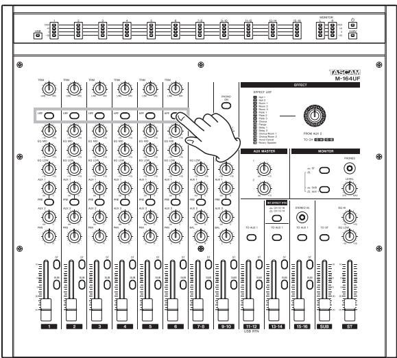
⑧ HPF switch (channels 1–6)
Push this switch in to turn ON the high-pass filter, which cuts frequencies below 80 Hz by 12 dB/octave. The high-pass filters affect inputs from both MIC and LINE input jacks.
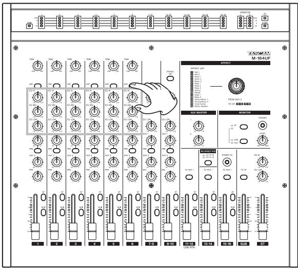
⑨ EQ knobs (channels 1–6)
These channels each have a 3-band EQ.
The EQ HI knob adjusts the high frequency range with a roll-off frequency of 12 kHz and a boost/cut range of ±15 dB.
The EQ MID knob adjusts the middle frequency range with a central frequency of 2.5 kHz and a boost/cut range of ±15 dB.
The EQ LOW knob adjusts the low frequency range, with a roll-off frequency of 100 Hz and a boost/cut range of ±15 dB.
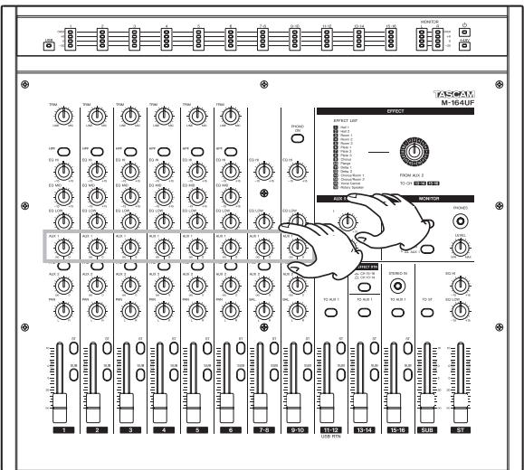
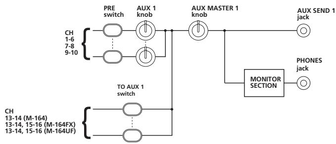
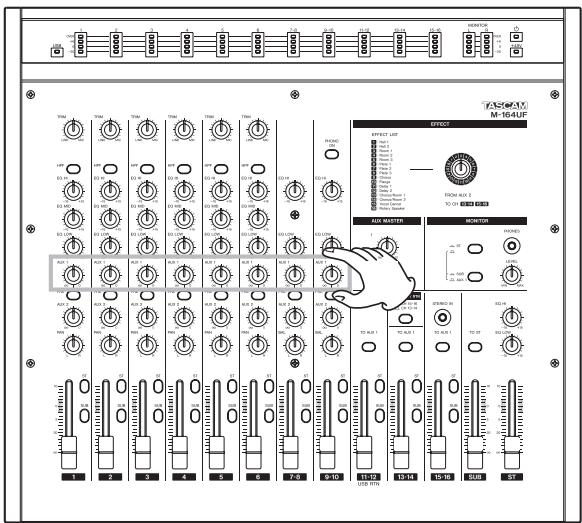
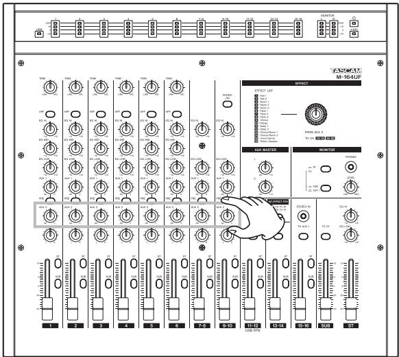
⑩ AUX 1 knobs (channels 1-6, 7-8, 9-10)
Use to adjust the level of the channel signals sent to the AUX 1 bus.
When the PRE switch is OFF (switch not pushed in), the post-fader signal (signal after being adjusted by the fader) is sent to the AUX 1 bus. When ON (switch pushed in) the pre-fader signal (signal after EQ adjustment but before fader adjustment) is sent to the AUX 1 bus. In addition to being output from the rear panel AUX SEND 1 jacks, the AUX 1 bus signal can also be monitored with headphones.
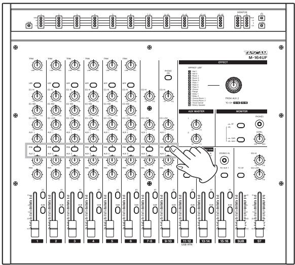
⑪ PRE switches (channels 1-6, 7-8, 9-10)
Use to set when the channel signal is sent to the AUX 1 bus. When OFF (switch not pushed in), the post-fader signal (signal after being adjusted by the fader) is sent to the AUX 1 bus, and when ON (switch pushed in), the pre-fader signal (signal after EQ adjustment but before fader adjustment) is sent.
⑫ AUX 2 knobs (channels 1-6, 7-8, 9-10)
Use to adjust the post-fader signal level (signal after being adjusted by the fader) of the channel signal sent to the AUX 2 bus.
In addition to outputting the AUX 2 bus signal from the rear panel AUX SEND 2 jacks, M-164FX and M-164UF units can also send these signals to the internal effects.
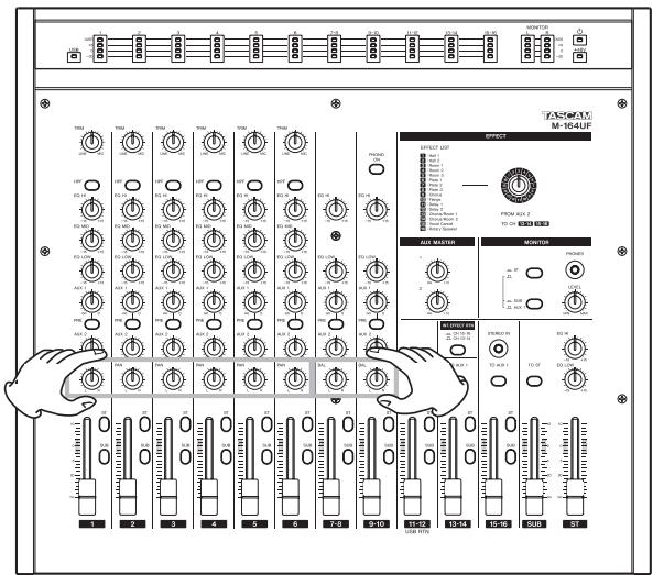
⑬ PAN knobs (channels 1-6)
Use to set the left-right position of the channel signals sent to the stereo and SUB busses.
⑭ BAL knobs (channels 7-8, 9-10)
Use to set the left-right balance of stereo channel signals sent to the stereo and SUB busses.
⑮ ST switches (all channels)
Turn ON (push switch in) to send a channel signal to the stereo (ST) bus.
⑯ SUB switches (all channels)
Turn ON (push switch in) to send a channel signal to the SUB bus.
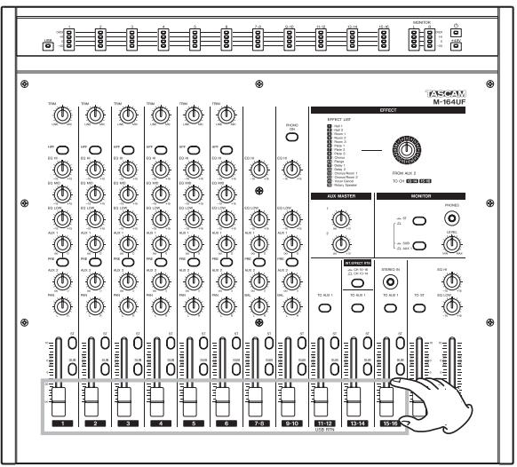
⑰ Channel faders (all channels)
Use to adjust the levels of channel signals sent.
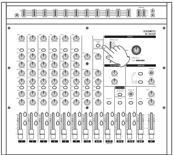
⑱ PHONO ON switch (channels 9-10)
Turn this switch ON (push switch in) when the output of a record player is connected to channels 9-10.
⑲* EFFECT rotary knob (M-164FX and M-164UF only)
Use to select the internal effect type. Turn left or right to select the number of the corresponding effect in the list to the left.
The internal effects stereo return output is sent to channels 13-14 or 15-16.
⑳ AUX MASTER (1, 2) knobs
Use to adjust the output levels of the AUX 1 and AUX 2 busses.
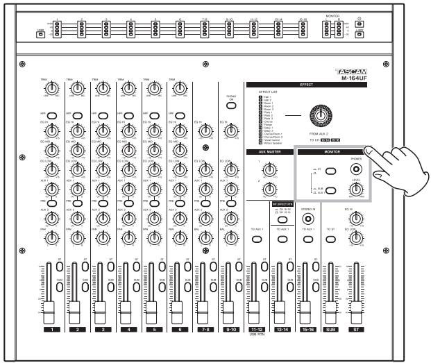
②1 MONITOR section ST switch
Turn ON (push switch in) to monitor the stereo bus signal through headphones. Turn OFF to monitor the SUB or AUX 1 bus.
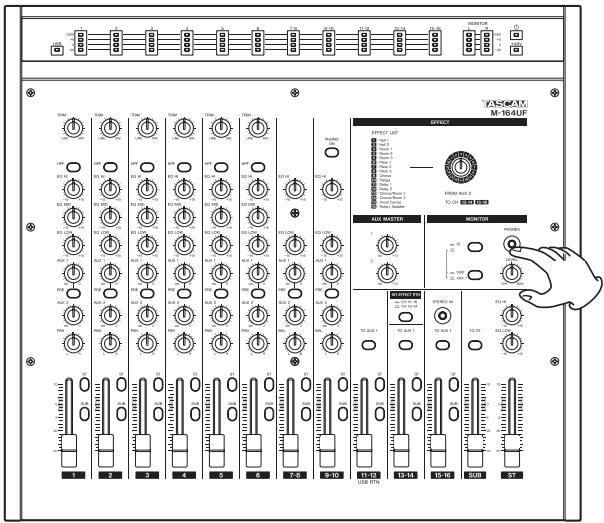
②2 PHONES jack (standard stereo jack)
Connect stereo headphones here. Depending on the MONITOR section switch settings, you can monitor the stereo, SUB or AUX 1 bus.
②3 MONITOR section SUB/AUX 1 switch
When the MONITOR section ST switch is OFF, push this switch in to monitor the SUB bus or leave it out to monitor the AUX 1 bus through headphones.
⑳ LEVEL knob
Use to adjust the signal level sent to the headphones.
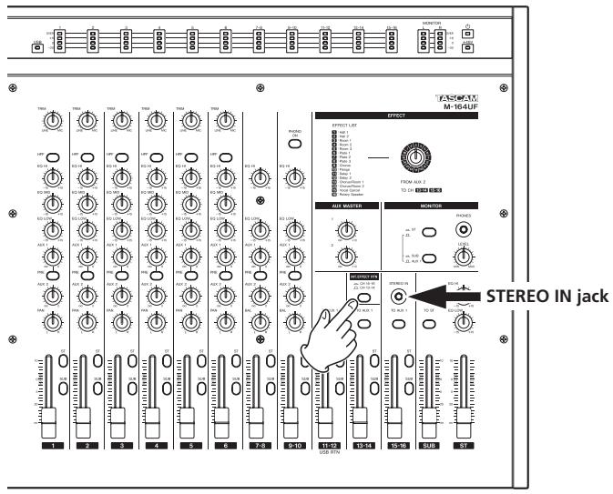
⑲ STEREO IN jack (stereo mini-jack)
Use this jack to connect an iPod or another external (stereo) sound source.
The connected source signal is sent to channels 15-16.
NOTE
On M-164FX and M-164UF mixers, when an input is connected to this jack, the input is given priority and the internal effects return signal is not sent to channels 15-16 even if the INT. EFFECT RTN switch described below is pushed in to set channels 15-16 as the internal effects return channels.
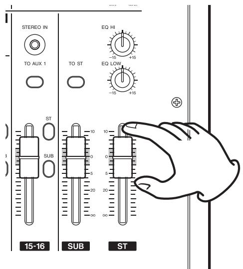
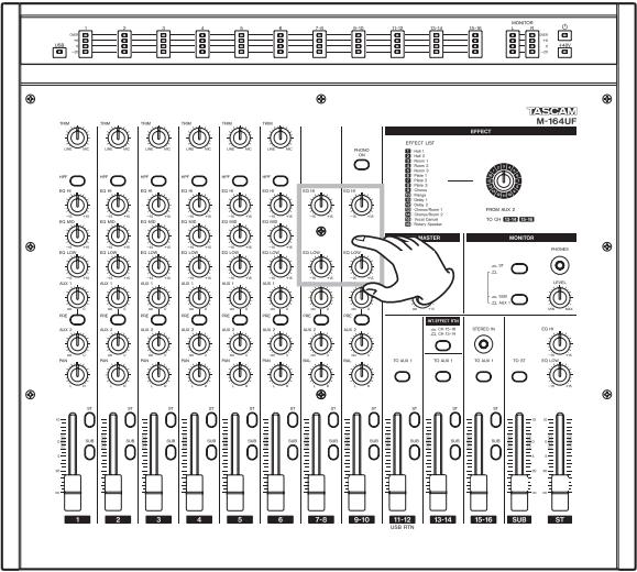
②6 EQ HI and EQ LOW knobs
Use this 2-band EQ on the stereo bus to adjust the sound character of the mixed stereo signal output.
The EQ HI knob adjusts the high frequency range, with a roll-off frequency of 12 kHz and a boost/cut range of ±15 dB.
The EQ LOW knob adjusts the low frequency range with a roll-off frequency of 100 Hz and a boost/cut range of ±15 dB.
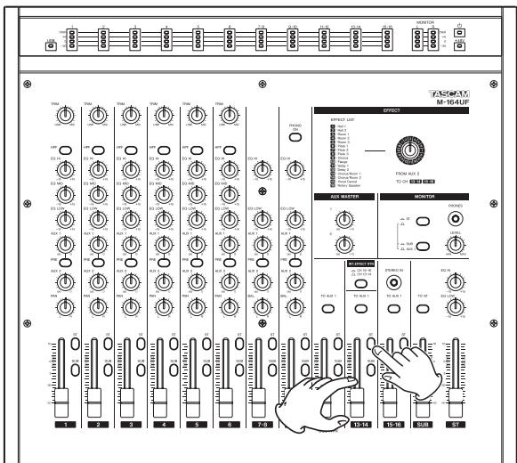
⑳*INT. EFFECT RTN switch (M-164FX and M-164UF)
This switch above the channel 13-14 fader of M-164FX and M-164UF mixers allows the selection of the internal effects return channels.
Channels 13-14 are selected as return channels when the switch is not pushed in, and channels 15-16 are selected when the switch is pushed in.
2 – Names and Functions of Parts
⑳ TO ST switch
Turn this switch ON (push switch in) to send the SUB bus output signal to the stereo bus.
⑲ TO AUX 1 switch(es)
The M-164 has one switch for channels 13-14.
The M-164FX has one switch each for both channel 13-14 and 15-16 pairs.
The M-164UF has one switch each for channel 11-12, 13-14 and 15-16 pairs.
When ON (switch pushed in), the post-fader signal (signal after being adjusted by the fader) is sent to the AUX 1 bus.
⑳ SUB fader
This is the SUB bus output fader.
③1 ST fader
This is the stereo bus output fader.
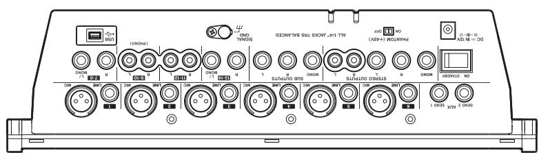
Rear panel
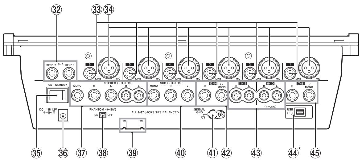
*M-164UF only
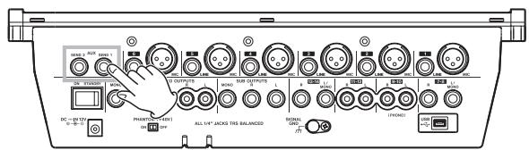
③2 AUX SEND 1 and 2 jacks (standard jacks)
These are balanced outputs for the AUX bus 1 and 2 signals. Unbalanced connections are also possible. Use with external effects or monitoring systems.
③3 LINE input jacks (standard jacks)
The outputs of electronic instruments, audio equipment and other line level signals can be connected to these input jacks. Both 3-pole balanced and 2-pole unbalanced standard plugs can be connected.
③4 MIC input connectors (XLR connectors)
These are balanced mic inputs wired for pin 2 to be hot.
③5 ON/STANDBY switch
Turns the mixer power ON and STANDBY.
③6 DC = IN 12V
Connect the included AC adaptor (TASCAM PS-1225L) here.
In order to prevent the cord from being accidentally disconnected during use, pass the cord through the cord holder.
③7 STEREO OUTPUTS jacks (standard and RCA pin jacks)
These output the stereo bus signals.
The standard jacks (L, R, MONO) output balanced signals, but connection with unbalanced cables is also possible. The MONO jack outputs a monaural signal.
The RCA pin jacks (L, R) output unbalanced signals.
③8 PHANTOM (+48V) switch
Use this to turn +48V phantom power to channel 1-6 MIC inputs ON and OFF.
CAUTION
Do not connect or disconnect mics when the PHANTOM (+48V) switch is ON.
⑲ Cord holder
Use this to hold the cord and prevent accidental disconnection of the plug.
④0 SUB OUTPUTS (standard jacks)
These output the SUB bus signals on balanced jacks, but connection with unbalanced cables is also possible. The MONO jack outputs a monaural signal.
④1 SIGNAL GND
When connecting a record player to channels 9-10, connect the player's grounding wire here.
NOTE
If humming occurs when external equipment other than a record player is connected to the mixer, connecting this jack with part of the metal frame of the external equipment (or the rack frame if rack mounted) with grounding wire might reduce the noise.
④2 13-14 input jacks (standard jacks)
The outputs of electronic instruments, audio equipment and other line level signals can be connected to these input jacks. Both 3-pole balanced and 2-pole unbalanced standard plugs can be connected.
If a connection is only made to the L/MONO input jack, the signal is sent to both left and right channels.
NOTE
On M-164FX and M-164UF mixers, do not connect anything to this input jack if the internal effects return channels are set to channels 13-14 (INT. EFFECT RTN switch not pushed in).
④3 9-10, 11-12 input jacks (RCA pin jacks)
The outputs of electronic instruments, audio equipment and other line level signals can be connected to these unbalanced input jacks.
A record player can also be connected to the 9-10 input jacks. When doing so, also connect the grounding wire from the record player to the SIGNAL GND jack and turn the PHONO ON switch on the top panel ON.
2 - Names and Functions of Parts
④4* USB port (M-164UF ONLY)
Connect the mixer to a computer from this port using the included USB cable.
④5 7-8 input jacks (standard jacks)
The outputs of electronic instruments, audio equipment and other line level signals can be connected to these input jacks. Both 3-pole balanced and 2-pole unbalanced standard plugs can be connected.
If a connection is only made to the L/MONO input jack, the signal is sent to both left and right channels.
3 – Preparation for Use
This chapter explains how to connect external equipment and the power cord, as well as how to make other preparations before turning on the power. See “5–Using with a Computer (M-164UF)” for an explanation of how to connect an M-164UF mixer with a computer.
Connecting the power
Confirm that the mixer power switch is set to STANDBY beforehand.
Connect the included power cord and AC adaptor (TASCAM PS-1225L) to the mixer.
The cord holder is an opening on the bottom of the mixer for securing the AC adaptor cord. When connecting the cord, pass it through the cord holder to prevent it from accidentally becoming disconnected during use.

CAUTION
- Always use the included AC adaptor (TASCAM PS-1225L). Use of a different AC adaptor could cause malfunction, generation of heat, fire or other trouble.
- Do not force the cord into the holder. Doing so could break the line.
Examples of connecting external equipment
Two connection examples follow.
For details about making connections, see “Making stereo output connections” and “Making input sound source connections.”
Precautions before making connections
- Turn the power OFF on all the equipment to be connected and set the mixer to standby.
- Plug in all pieces of equipment into the same outlet or power strip so that they will receive power from the same line.
To minimize power voltage fluctuation when using an extension cord, for example, use a heavy cable with high electrical current capacity.
Connection example 1: Using an M-164 with multiple mics and for background music in a club
flowchart
graph TD
    A["CD player"] -->|Record player| B["External effect unit"]
    B -->|13-14 (L, R)| C["AUX SEND 1"]
    C --> D["AUX 2 AUX"]
    D --> E["Connect mics to MIC (1-6)"]
    E --> F["CD player"]
    F --> G["CD-160MAE"]
    G --> H["Stereo amplifier"]
    H --> I["External effect unit"]
    style A fill:#f9f,stroke:#333
    style B fill:#ccf,stroke:#333
    style C fill:#cfc,stroke:#333
    style D fill:#fcc,stroke:#333
    style E fill:#cff,stroke:#333
    style F fill:#ffc,stroke:#333
    style G fill:#cfc,stroke:#333
    style H fill:#fcc,stroke:#333
    style I fill:#ffc,stroke:#333
iPod
3 – Preparation for Use
Connection example 2: Using an M-164UF for recording in a home studio
flowchart
graph TD
    A["Audio Speaker"] -->|AUX SEND 2| B["Stereo amplifier"]
    C["Audio Speaker"] -->|AUX SEND 1| D["External effect unit"]
    E["Audio Speaker"] -->|AUX SEND 2| F["CD player"]
    G["Audio Speaker"] -->|AUX SEND 2| H["Stereo amplifier"]
    I["Audio Speaker"] -->|AUX SEND 2| J["CD player"]
    K["Electronic keyboard"] -->|7-8 (L, R)| L["Computer"]
    M["Electronic keyboard"] -->|USB| N["Rhythm machine"]
    O["Electronic keyboard"] -->|USB| N
    P["Electronic keyboard"] -->|USB| N
    Q["Electronic keyboard"] -->|USB| N
    R["Electronic keyboard"] -->|USB| N
    S["Electronic keyboard"] -->|USB| N
    T["Electronic keyboard"] -->|USB| N
    U["Electronic keyboard"] -->|USB| N
    V["Electronic keyboard"] -->|USB| N
    W["Electronic keyboard"] -->|USB| N
    X["Electronic keyboard"] -->|USB| N
    Y["Electronic keyboard"] -->|USB| N
    Z["Electronic keyboard"] -->|USB| N
    AA["Electronic keyboard"] -->|USB| N
    AB["Electronic keyboard"] -->|USB| N
    AC["Electronic keyboard"] -->|USB| N
    AD["Electronic keyboard"] -->|USB| N
    AE["Electronic keyboard"] -->|USB| N
    AF["Electronic keyboard"] -->|USB| N
    AG["Electronic keyboard"] -->|USB| N
    AH["Electronic keyboard"] -->|USB| N
    AI["Electronic keyboard"] -->|USB| N
    AJ["Electronic keyboard"] -->|USB| N
    AK["Electronic keyboard"] -->|USB| N
    AL["Electronic keyboard"] -->|USB| N
    AM["Electronic keyboard"] -->|USB| N
    AN["Electronic keyboard"] -->|USB| N
    AO["Electronic keyboard"] -->|USB| N
    AP["Electronic keyboard"] -->|USB| N
    AQ["Electronic keyboard"] -->|USB| N
    AR["Electronic keyboard"] -->|USB| N
    AS["Electronic keyboard"] -->|USB| N
    AT["Electronic keyboard"] -->|USB| N
    AU["Electronic keyboard"] -->|USB| N
    AV["Electronic keyboard"] -->|USB| N
    AW["Electronic keyboard"] -->|USB| N
    AX["Electronic keyboard"] -->|USB| N
    AY["Electronic keyboard"] --> AZ["External effect unit"]
    BA["Electronic keyboard"] --> BB["Connect mics to MIC (1-6)"]
    BC["Electronic keyboard"] --> BD["Computer"]
    BE["Electronic keyboard"] --> BF["Rhythm machine"]
    BG["Electronic keyboard"] --> BH["Computer"]
Making stereo output connections
CAUTION
Turn the power OFF on all equipment to be connected and set the mixer to standby before making connections.
The mixer stereo bus output is usually used as the main output and connected to an external amplifier or speaker system. Depending on the type of amplifier, use the STEREO OUTPUTS standard jacks (L, R) or the RCA pin jacks (L, R). The standard jacks provide balanced outputs, but unbalanced cables can also be used to connect to amplification systems with unbalanced inputs.
TIP
- Using the MONO jack instead of the L and R jacks is convenient when connecting to a mono amplifier.
- Using both the STEREO OUTPUTS and SUB OUTPUTS is convenient for connecting two amplification or speaker systems at the same time, including setups with main and sub speakers or main and monitor speakers. Each output pair has a dedicated fader, so you can set their levels independently with the mixer.
- By connecting the SUB OUTPUTS to a recorder, you can record the same stereo mix signal as it is output from an amplification or speaker system.
Connecting headphones
To monitor with headphones, connect stereo headphones to the PHONES jack on the top panel.
Making input sound source connections
CAUTION
Turn the power OFF on the mixer and all equipment to be connected before making connections.
Connecting mics
Connect mics to the channel 1–6 MIC input jacks (XLR). When using condenser mics that require phantom power, turn the PHANTOM (+48V) switch on the rear panel ON.
Use the PHANTOM (+48V) switch to turn the phantom power supply to all channels (1–6) ON or OFF simultaneously. When the PHANTOM (+48V) switch is ON, if you want to use dynamic mics at the same time as condenser mics, always connect the dynamic mics using balanced connections.
3 – Preparation for Use
CAUTION
- Connecting a dynamic mic with an unbalanced connection could damage it if the PHANTOM (+48V) switch is ON.
- Do not connect or disconnect mics when the PHANTOM (+48V) switch is ON. Doing so could cause loud noise or damage the equipment.
NOTE
- When the PHANTOM (+48V) switch is ON (and the mixer power is ON) the +48V indicator lights on the right side of the meter panel.
- The XLR connector #2 pins are "hot" on this mixer.
Connecting synthesizers, other sound sources and audio equipment (line level sound sources)
Line level sound sources can be connected to every channel (1–16). However, the types of jacks and mixer functions differ depending on the channel. Channels 7–16 are five pairs of stereo channels, and channels 9-10 can also be connected to a record player.
Channels 1–6
- Connect using the standard (LINE) jacks. These jacks are balanced, but they can also be connected with unbalanced sound sources.
- Use the TRIM knobs on the top panel to adjust the input levels (see “Adjusting levels” on page 18). The mixer channel functions include a high-pass filter, a 3-band EQ, AUX 1 and 2 sends and pan.
Channels 7-8
- Connect a stereo sound source using standard jacks (L, R). These jacks are balanced, but they can also be connected with unbalanced sound sources.
- If a mono sound source is connected to the L jack, the L input signal is sent to both channels 7 and 8.
- The mixer channel functions include a 2-band EQ, AUX 1 and 2 sends and balance.
Channels 9-10
- Connect a stereo sound source using RCA pin jack jacks (L, R).
- A record player can be connected to these jacks. When doing so, press in the PHONO ON switch on the top panel. In addition, connect the grounding wire from the record player to the SIGNAL GND jack.
- The mixer channel functions include a 2-band EQ, AUX 1 and 2 sends and balance.
Channels 11-12
- Connect a stereo sound source using RCA pin jack jacks (L, R).
- On M-164UF mixers, the stereo audio output from a computer connected by USB is also input to channels 11-12. The signals from these channels can also be sent to AUX 1.
Channels 13-14
- Connect a stereo sound source using standard jacks (L, R). These jacks are balanced, but they can also be connected with unbalanced sound sources.
- If a mono sound source is connected to the L jack, the L input signal is sent to both channels 13 and 14.
- On M-164FX and M-164UF mixers, if the INT. EFFECT RTN switch is not pushed in, the internal effects return signal is input to channels 13-14.
CAUTION
- On M-164FX and M-164UF mixers, when connecting an external sound source to the standard jacks of channels 13-14, push the INT. EFFECT RTN switch in to set channels 15-16 as the internal effects return channels. If the INT. EFFECT RTN switch is not pushed in, the signal from the external sound source connected to the standard jacks of channels 13-14 and the internal effects return signal will interfere with each other and neither signal will be input correctly.
- The signals from channels 13-14 can also be sent to AUX 1.
Channels 15-16
- Connect a stereo sound source to the STEREO IN jack on the top panel. This stereo mini-jack is convenient for connecting iPods and similar devices.
CAUTION
On M-164FX and M-164UF mixers, when a plug is connected to the STEREO IN jack, this external input is prioritized even if the INT. EFFECT RTN switch is pushed in, setting channels 15-16 as the internal effects return channels. As a result, the effects signal will not be returned to these channels. Therefore, when using this jack, set the internal effects return to channels 13-14.
- On the M-164FX and M-164UF models, the signals from channels 15-16 can also be sent to AUX 1.
Setting the internal effects return channels (M-164FX and M-164UF)
When using the internal effects of an M-164FX or M-164UF mixer, either channels 13-14 or 15-16 can be used as the return channels. Use the INT. EFFECT RTN switch to select the return channels.
When using the channel 13-14 input jacks on the rear panel, push the INT. EFFECT RTN switch in to select channels 15-16 as the return channels. When using the channel
15-16 STEREO IN jack on the top panel, select channels 13-14 as the return channels by setting the INT. EFFECT RTN switch so that it is not pushed in.
NOTE
When using channels 13-14 as the return channels, do not use the channel 13-14 input jacks on the rear panel. When using channels 15-16 as the return channels, do not use the STEREO IN jack on the top panel.
Turning the power on and putting the mixer in standby
Before turning the power on
1 Prepare the mixer as follows.
Set the EQ, PAN and BAL knobs to their center positions.
Turn other knobs completely to the left (minimum).
Lower faders completely (minimum).
Turn switches OFF (not pushed in).
2 Minimize the output levels of sound sources and the input levels of amplifying equipment connected to the mixer.
Turning on the power
1 Turn the mixer power ON using the ON/STANDBY switch on the rear panel of the mixer.
The indicator ⏻ on the right of the meter panel lights.
2 Turn the power of the connected input sound source equipment ON.
3 Finally turn the power of the connected amplification system ON.
Putting the mixer in standby
To put the mixer in standby, reverse the procedures above. Failure to do so might cause noise that could damage the equipment.
Adjusting levels
After turning on the power, adjust the level of each input signal. The following explanation assumes that the STEREO OUTPUTS are being used as the main outputs.
1 Prepare headphones or an amplification system to output the sound in advance.
If monitoring with headphones, raise the volume with the PHONES LEVEL knob slightly.
If monitoring with an amplification system, raise the input level on the amp slightly.
With this set, the level of the signals output from the STEREO OUTPUTS jacks is shown on the MONITOR meters.
3 Raise the ST (stereo) fader to the 0 position.
4 For the channel 1–6 inputs, adjust the TRIM knob for the channel so that the "0" indicator on the channel level meter lights when a signal is being input that is at the loudest level ordinarily expected.
For the channel 7–16 inputs, adjust the level at the sound source so that the “0” indicator on the channel level meter lights when a signal is being input that is at the loudest level ordinarily expected.
5 Raise the channel fader.
CAUTION
Even if there is no meter indication or no signal is being output despite the fact that a signal is being input, do not raise the faders carelessly. The operation of other switches or features could cause a loud signal to be output suddenly, possibly damaging speakers or other equipment. Sudden loud noises could also harm your hearing.
TIP
The best settings for audio quality are when the input meter "0" indicator lights, and the channel fader or ST fader is set in the range around 0 (where the fader scale on the mixer is highlighted). If the fader is set to an extremely low value, we recommend lowering the amp volume and then raising the fader. On the other hand, if the fader is too high, we recommend raising the amp volume and lowering the fader.
Using the mixer channel functions
High-pass filter (HPF)
Press the HPF switch to turn the high-pass filter ON and cut frequencies of 80 Hz or less by -12 dB/octave. The high-pass filter affects inputs from both MIC and LINE input jacks, but it is especially effective when using mics for reducing unwanted noise from wind and breathing.
EQ
Channels 1–6 have 3-band equalization (EQ) with HI, MID and LOW frequency boost and cut adjustment ranges of ±15 dB.
The HI band is a shelving EQ. Use the EQ HI knob to boost or cut the frequency band above 12 kHz.
The MID band is a peaking EQ with 2.5 kHz as the central frequency. Use the EQ MID knob to boost or cut mid frequencies.
The LOW band is a shelving EQ. Use the EQ LOW knob to boost or cut the frequency band below 100 Hz.
4 - Using the mixer
Channels 7-8 and 9-10 have 2-band EQ with HI and LOW shelving frequency boost and cut adjustment ranges of ±15 dB.
Use the EQ HI knob to boost or cut the frequency band above 12 kHz, and use the EQ LOW knob to boost or cut the frequency band below 100 Hz.
AUX sends
The mixer has 2 AUX busses (AUX 1, AUX 2).
AUX 1
Signals from channels 1–6, 7-8 and 9-10 can be sent to the AUX 1 bus by adjusting their AUX 1 knob levels. Use the AUX MASTER 1 knob to set the final level of the AUX 1 bus signal that is output from the AUX SEND 1 jack on the rear panel. You can also monitor the AUX 1 signal using headphones attached to the mixer.
flowchart
graph TD
    A["PRE switch"] --> B["AUX 1 knob"]
    C["TO AUX 1 switch"] --> B
    D["AUX MASTER 1 knob"] --> B
    E["AUX SEND 1 jack"] --> F["MONITOR SECTION"]
    G["PHONES jack"] --> F
    H["CH 1-6 7-8 9-10"] --> A
    I["CH 13-14 (M-164) 13-14, 15-16 (M-164FX) 13-14, 15-16 (M-164UF)"] --> J
You can set whether the signal sent to the AUX 1 bus is pre-fader or post-fader. When the PRE switch is ON (switch pushed in), the signal is sent to the AUX 1 bus after EQ adjustment but before fader adjustment so the fader position has no effect. When the PRE switch is OFF (switch not pushed in), the signal is sent to the AUX 1 bus after being adjusted by the fader.
Ordinarily, if you want to use AUX 1 for stage or cue monitoring, turn the PRE switch ON to create a mix that is entirely independent from the main mix. To use AUX 1 as an effect send, turn the PRE switch OFF.
In addition, there is a TO AUX 1 switch on channels 13-14 on all M-164 mixers, as well as on channels 15-16 on M-164FX and M-164UF mixers and channels 11-12 on M-164UF. Turn this ON to send the post-fader signal to the AUX 1 bus. For example, input an effect return to a pair of these channels, and use this switch to set whether or not to send this to a monitoring setup on the AUX 1 bus.
AUX 2
Signals from channels 1–6, 7-8 and 9-10 can be sent to the AUX 2 bus by adjusting their AUX 2 knob levels.
The signal sent to the AUX 2 bus is always post-fader, so the AUX 2 bus is usually used for an effect send. Use the AUX MASTER 2 knob to set the final level of the AUX 2 bus signal that is output from the AUX SEND 2 jack on the rear panel.
On M-164FX and M-164UF mixers, the AUX 2 signal is also sent to the internal effects. (See “Using internal effects (M-164FX and M-164UF)” on page 23.)
Pan And Balance
For channels 1–6, use the PAN knob to set the left-right stereo position of the channel signal sent to the stereo and SUB busses.
For stereo channels 7-8 and 9-10, use the BAL knob to set the left-right balance of the stereo channel signals sent to the stereo and SUB busses.
Stereo channels 11-12, 13-14 and 15-16 do not have left-right balance control.
Bus assignments
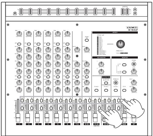
Using the ST and SUB switches, the outputs of channels 1–16 can be sent to the stereo and SUB busses.
Turn both ST and SUB switches OFF to cut (mute) the output of a channel easily.
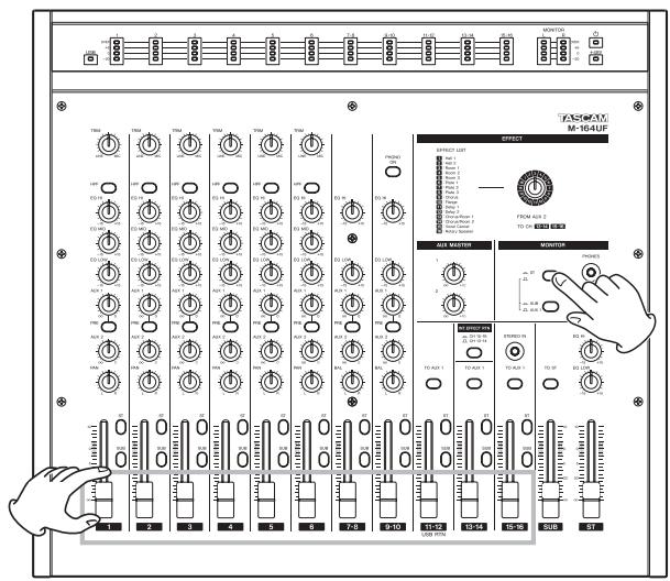
Monitoring with headphones
You can monitor the outputs of the mixer's stereo, SUB or AUX 1 send bus.
1 Connect stereo headphones to the PHONES jack on the top panel of the mixer.
2 Raise the PHONES knob level slightly.
3 Use the two switches in the MONITOR section to set whether the stereo, SUB or AUX 1 send bus is monitored.
- Push in the upper switch to monitor the stereo bus signal. (The status of the bottom switch has not effect.)
- Without pushing in the upper switch, push in the lower switch to monitor the SUB bus.
- Do not push in either the upper or lower switch to monitor the AUX 1 send bus.
Using AUX 1 for a monitoring mix
By using the AUX 1 bus to output a pre-fader signal mix, you can use this for stage and cue monitoring setups, as explained in “AUX sends” in “Using the mixer channel functions.”
Pre-fader signal levels can be sent to the AUX 1 bus for channels 1–6, 7-8 and 9-10.
NOTE
The TO AUX 1 switches on channels 13-14 on all M-164 mixers, as well as on channels 15-16 on M-164FX and M-164UF mixers and channels 11-12 on M-164UF, can be used to send post-fader signals to the AUX 1 bus. Prefader signals cannot be sent from these channels.
Connect an amplification or speaker system to the AUX SEND 1 jack or connect headphones to the mixer in advance, to allow monitoring of AUX 1. (See “Monitoring with headphones” on page 21.)
4 - Using the mixer
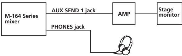
flowchart
graph LR
    A["M-164 Series mixer"] -->|AUX SEND 1 jack| B["AMP"]
    A -->|PHONES jack| C["Stage monitor"]
1 Turn ON (push in) the PRE switch under the AUX 1 knob of each channel that you want to monitor.
2 Use each channel's AUX 1 knob to adjust the signal level sent for monitoring.
3 Use the AUX MASTER 1 knob to adjust the overall level sent to the AUX 1 send bus.
Using sub-group functions
By using the SUB bus as a sub-group, you can make adjusting the stereo mix balance more efficient.
For example, in a live application when connecting drum mics to channels 1–3, and inputting guitar, bass, and vocal on channels 4–6, turn the ST assign switches OFF and the SUB assign switches ON for channels 1–3. Turn the ST assign switches ON and the SUB assign switches OFF for channels 4–6. Then turn the TO ST switch above the SUB fader ON.
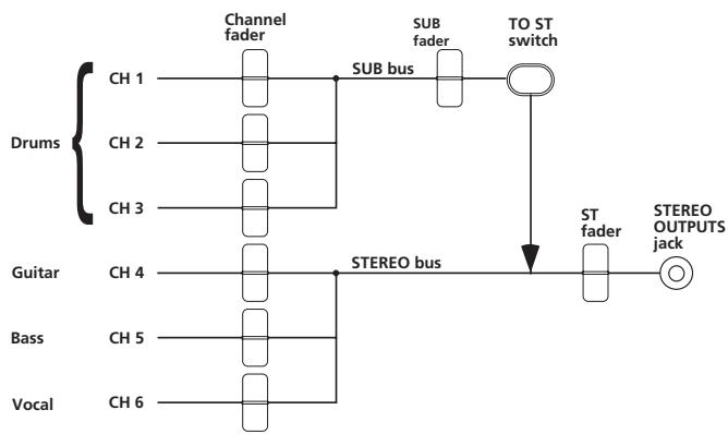
flowchart
graph TD
    A["Drums"] --> B["Channel fader"]
    B --> C["SUB bus"]
    C --> D["TO ST switch"]
    D --> E["ST fader"]
    E --> F["STEREO OUTPUTS jack"]
    G["Guitar"] --> H["STEREO bus"]
    I["Bass"] --> H
    J["Vocal"] --> H
    H --> E
With this setting, the guitar, bass and vocal signals are sent directly to the stereo bus, but the drums signals pass through the SUB bus before being sent to the stereo bus. By doing this, after adjusting the balance of the three drum mics, you can use the SUB fader to adjust the overall level of the drums when balancing with the other sound sources.
Using the internal effects (M-164FX and M-164UF)
M-164FX and M-164UF units have an internal effects capability that allows the use of an effect without connecting an external effect unit.
These internal effects can be applied by sending signals from channels 1–6, 7-8 and 9-10 to the AUX 2 bus. The return signal can be sent to channels 13-14 or 15-16.
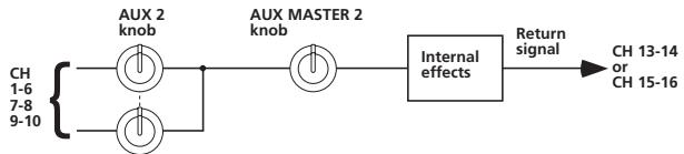
flowchart
graph LR
    A["AUX 2 knob"] --> C["Internal effects"]
    B["AUX MASTER 2 knob"] --> C
    C --> D["Return signal"]
    E["CH 1-6\n7-8\n9-10"] --> A
    E --> B
    F["CH 13-14 or CH 15-16"] --> D
1 Use the AUX 2 knob of each channel to adjust the level of the channel signal sent to the effects.
2 Use the AUX MASTER 2 knob to adjust the overall level of the signal sent to the effects.
3 Use the EFFECT section rotary knob to select the effect type. The effect types are explained in the list below by their corresponding numbers.
| No. | Effect name | Description |
| 1 | Hall 1 | Bright hall reverb suitable for drums, guitars and vocals |
| 2 | Hall 2 | Warm hall reverb suitable for acoustic guitars, pianos and vocals |
| 3 | Room 1 | Simulation of a room with hardwood walls and floor suitable for acoustic instruments |
| 4 | Room 2 | Ambience suitable for acoustic mixes and synth sounds |
| 5 | Room 3 | Warm room sound suitable for guitars and rhythm instruments |
| 6 | Plate 1 | Classic plate reverb suitable for lead vocals and lead instruments |
| 7 | Plate 2 | Bright and showy plate reverb suitable for vocals and drums |
| 8 | Plate 3 | Short vintage plate reverb suitable for snare drums and guitars |
| 9 | Chorus | Stereo chorus suitable for guitars and pianos |
| 10 | Flange | Stereo flanger creates a jet-like sound |
| 11 | Delay 1 | 125-ms slapback delay suitable for vocals and guitars |
| 12 | Delay 2 | 190-ms delay suitable for percussive arpeggios |
| 13 | Chorus/Room 1 | Chorus/reverb suitable for guitars, synths and pianos |
| 14 | Chorus/Room 2 | Autowah guitar effect with reverb suitable for lead instruments |
| 15 | Vocal Cancel | Effect that reduces the lead vocals from commercial CDs and other sources |
| 16 | Rotary Speaker | Emulation of a rotary speaker suitable for organs and guitars |
4 - Using the mixer
4 Select the input channel for the return signal.
Push the INT. EFFECT RTN switch in to send the return signal to channels 15-16. Leave the switch out (do not press it in) to send the return signal to channels 13-14.
CAUTION
Do not connect anything to the STEREO IN jack when using channels 15-16 for the return signal. Doing so cuts (mutes) the return signal.
TIP
When connecting an iPod or other device to the STEREO IN jack on channels 15-16, set the INT. EFFECT RTN switch to channels 13-14 (pressed in) to send the return signal to these channels.
5 Turn the ST switch ON for the input channel receiving the return signal, and use its fader to adjust return levels.
NOTE
When using AUX 1 for stage or cue monitoring, if you want to monitor the sound with the effect applied, turn the TO AUX 1 switch ON for the input channel receiving the return signal.
Using external effects
External effects can also be used with this mixer.
Channels 1–6, 7-8 and 9-10 can have an external effect applied by sending their signals to the external effect through the AUX 1or AUX 2 bus. The return signal can be input into any other channels as desired.
In the following explanation, the signals are sent through the AUX 2 bus to an external effect, and the return signals are received by channels 13-14.
NOTE
- When sending signals to an external effect through AUX 1, turn the PRE switch OFF to send the post fader signal.
- When receiving external effect signals back through channels 13-14, do not set the internal effect return to channels 13-14 (by setting the INT. EFFECT RTN switch to CH 13-14).
TIP
- If the AUX 2 bus is used to send signals to an external effect, the AUX 1 bus can still be used for monitoring.
- With M-164 FX and M-164 UF units, by sending AUX 1 to an external effect and AUX 2 to the internal effect, two types of effects can be used.
First, connect the input jack of the external effect to the AUX SEND 2 jack first, and connect the external effect output jacks to the L/R input jacks of mixer channels 13-14.
flowchart
graph TD
    A["AUX 2 knob"] --> B["AUX MASTER 2 knob"]
    C["AUX 1-6 7-8 9-10"] --> A
    D["AUX 13-14 L/R jcak"] --> E["External effect"]
    F["AUX SEND 2 jack"] --> E
    E --> G["Output terminal"]
    H["Input terminal"] --> E
1 Use the AUX 2 knob of each channel to adjust the level of the channel signal sent to the effect.
2 Use the AUX MASTER 2 knob to adjust the overall level of the signal sent to the effect.
3 Set the effect as desired.
4 Turn the ST switch for channels 13-14 ON, and use its fader to adjust the return level.
TIP
When using the AUX 1 bus for monitoring, turn the TO AUX 1 switch for channels 13-14 ON to also monitor the effect return signal.
Using a record player
An analog record player can be directly connected to mixer channels 9-10.
Make the following connections and settings to use an analog record player with this mixer.
- Connect the record player audio output to the channel 9-10 input jacks on the rear panel of the mixer.
- Connect the record player grounding wire to the SIGNAL GND jack on the rear panel of the mixer.
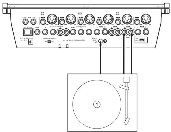
Record player
- Turn the PHONO ON switch on the top panel ON (push switch in).
NOTE
The output signals of analog record players are different from ordinary line output signals. If the connections and settings described above are not made, the playback sound will not be correct.
Making final adjustments to the main output sound
The stereo bus has a 2-band EQ with HI and LOW shelving that can be used to adjust the sound of the mix overall.
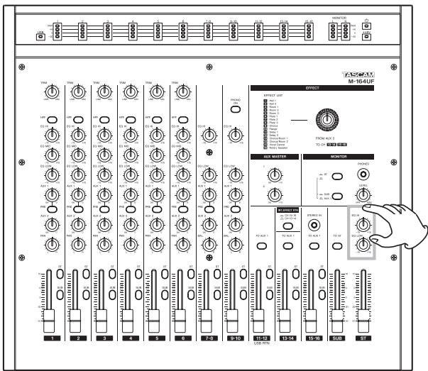
The EQ HI and EQ LOW knobs can boost and cut the high and low frequency ranges by ±15 dB.
Use the EQ HI knob to boost or cut the frequency band above 12 kHz, and use the EQ LOW knob to boost or cut the frequency band below 100 Hz.
5 – Using with a Computer (M-164UF)
When connected with a computer by USB, the M-164UF mixer can function as a USB 2.0 interface. Using the included Cubase LE4 or another audio application, you can easily create music on your computer. In addition, you can input a sound that you have created or edited on the computer into the M-164UF mixer, and mix it with live playing in a performance application.
Functions
- The M-164UF mixer can simultaneously send independent signals of input channels 1–10 and the AUX 1/2, STEREO and SUB busses to the computer.
Since the input channel signals sent to the computer are post-fader signals, the HPF, EQ and fader M-164UF mixer settings do affect them.
The output level settings of the AUX 1/2, STEREO and SUB busses (AUX MASTER 1 and 2 knobs, ST and SUB fader settings) also affect their signals. - The stereo output from the computer can also be sent to the M-164UF mixer by USB.
The stereo signals sent from the computer are input on the 11-12 channels of the M-164UF mixer, so it is possible to mix and output them from the mixer together with other input signals.
Installation
System requirements
Windows
Supported operating system:
32 bit Windows XP SP3 (except MCE), 32 bit Windows Vista SP1, 64 bit Windows XP SP2, 64 bit Windows Vista SP1
Recommended system:
- CPU: Pentium 4 1.4 GHz/AMD Athlon 1.4 GHz or higher (or equivalent processor)
- RAM: 512 MB or more memory: 32 bit Windows XP, 32 bit Windows Vista 1 GB or more memory: 64 bit Windows XP, 64 bit Windows Vista
• HDD: 1 GB or morefree space
• Audio device that supports ASIO
- DVD-ROM drive
- Internet connection
- USB 2.0 port
These requirements must be satisfied if you plan to use Cubase LE 4 (bundled with the M-164UF). If you are planning to use other application software, please consult its technical documentation for operating requirements specific to that software.
NOTE
- The number of available audio tracks will depend on the speed of your hard disk. A faster hard disk will facilitate smoother and easier operation.
• USB1.1 is not supported. - For memory, we recommend at least 512 MB for 32-bit systems and 1 GB for 64-bit systems (at least 2 GB for Windows Vista). When using digital audio applications, however, the more memory available, the smoother the performance is generally.
- M-164UF operation has been confirmed using standard computers that meet the above system requirements, but we cannot guarantee operation with computers that meet the above conditions in every case. Even under the same conditions, processing capabilities vary due to differences in the unique design specifications of each computer and its operating environment.
Mac OS X
Supported operating system:
Mac OS X version (10.4.11 or later, 10.5.6 or later)
Recommended system:
- CPU: Power PC G4 1 GHz or higher, Core Solo 1.5 GHz or higher
• RAM: 512 MB or more memory
• HDD: 1 GB or more free space - USB 2.0 port
• Audio device that supports Core Audio or ASIO - DVD-ROM drive
- Internet connection
For Macintosh systems as well, additional memory and a faster hard disk drive will facilitate smoother and easier operation of digital audio application software.
Installing the drivers
Before you can use the M-164, you must install the appropriate drivers on your computer. As described below, this is a simple process that uses the CD-ROM included with the M-164.
Drivers are updated from time to time. You can download the latest version of the drivers from the TASCAM website http://www.tascam.com/.
5 – Using with a Computer (M-164UF)
When installing the driver, start with the M-164UF mixer disconnected.
CAUTION
- Handle the enclosed CD-ROM with care. If the disc becomes scratched or dirty, your computer may be unable to read it and you may be unable to install the software.
If the disc becomes unreadable, you can request a replacement disc for a fee. - Do not try to play the included CD-ROM disc on an ordinary audio CD player. The noise produced could damage the speakers or harm your hearing.
Installing the drivers for Windows
The US-1641's drivers are provided on the CD-ROM as an executable installer.
You can also download the latest version of the driver from the TASCAM website (www.tascam.com).
If the driver on the included CD-ROM is an older version, we recommend that you download the latest version and install it
Installation procedures
The following are detailed explanations (for a Windows XP system) of how to install the driver from the included CD-ROM and how to update the firmware.
CAUTION
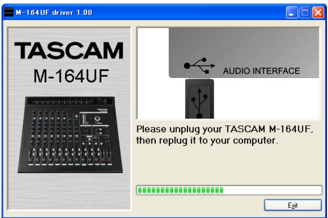
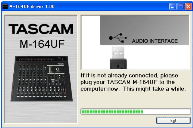
When installing the driver, it is necessary to disconnect and reconnect the USB cable during steps 7, 8 and 9. During this time, complete the procedures indicated on the screen within about a minute. Failure to complete the procedures quickly could result in the installation failing.
Installing the drivers
1 Make sure that the unit (M-164) is not connected to your computer via a USB cable.
2 Insert the included driver installation CD-ROM into the CD-ROM drive on your computer.
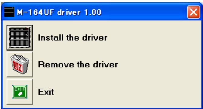
3 Click the Install M-164 Driver button when the menu screen below appears.
If the menu screen does not appear, find and open the "M-164UF_Install.exe" file on the driver.

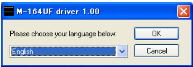
4 When the language selection screen appears after a short time, use the up and down arrow keys to select the desired language and then click the "OK" button.
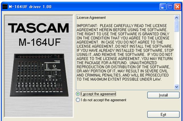
5 When the screen below appears, click the Install the driver button.
5 – Using with a Computer (M-164UF)
6 Read the contents of the License Agreement, then select I accept the agreement if you agree to the terms. Click the Install button to start installation.
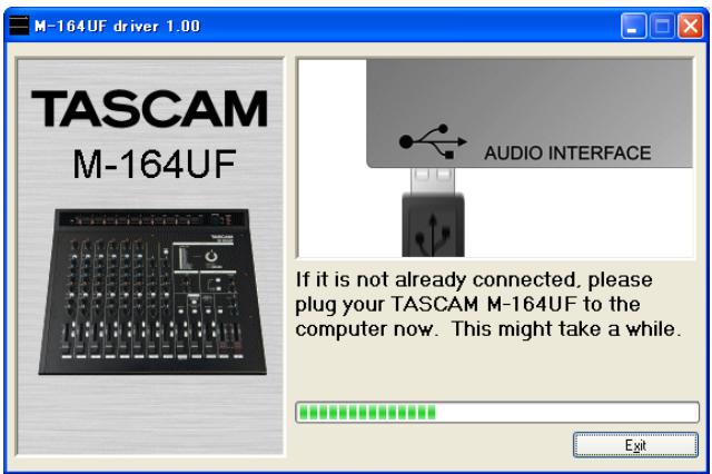
7 When the following screen appears, use the included USB cable to connect the mixer (M-164UF) with the computer.
8 When the following screen appears, disconnect the USB cable from the mixer (M-164UF) or the computer for a moment.
9 When the following screen appears, reconnect the mixer (M-164UF) and the computer with the USB cable.
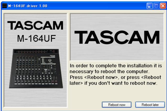
10 When the following screen appears, installation has completed.
Click the Reboot now button to restart the computer.
11 After the computer restarts, click TASCAM M-164UF (Start > Settings > Control Panels) to launch the M-164UF Control Panel. If information about the driver version, device and other details appear, installation has been successful.
Installation of Mac OS X drivers
1 Confirm that the M-164UF and computer are not connected.
2 Double-click the M-164UF_Drivers.mpkg on the included CD-ROM to launch the installer software.
3 Follow the instructions shown on screen to proceed with the installation.
4 After the computer restarts, connect the mixer.
How to update the firmware
By connecting the M-164UF with a computer by USB, you can overwrite the mixer firmware.
The latest firmware updater can be downloaded from our http://www.tascam.com website.
Preparation 1: Install the latest driver on your computer.
Preparation 2: Connect the M-164UF to be updated to the computer by USB.
NOTE
The firmware updater differs according to the version.
Updating the firmware with Windows
The following is an explanation of the procedures for updating the firmware using a Windows XP computer. When using a Windows Vista computer, the screens differ, but the procedures are fundamentally the same.
1 Connect the mixer and computer by USB.
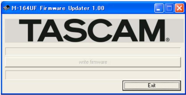
2 Launch the Windows XP firmware updater file for the version that you want to update.
The following screen appears.
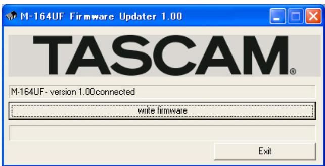
3 Click the write firmware button to start updating the firmware.
When updating completes, the following screen appears.
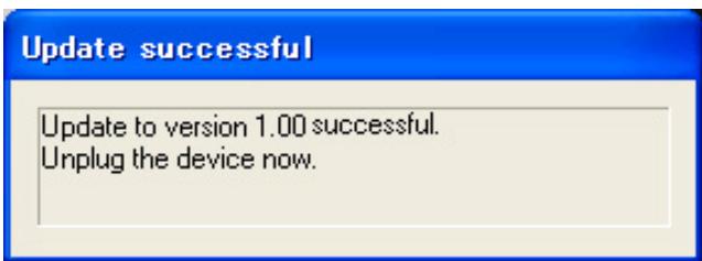
4 Disconnect the USB cable from the mixer.
The next screen appears.
5 Click the Exit button to complete updating.
Updating the firmware with Macintosh (OS X)
1 Connect the mixer and the Mac by USB.
2 Launch the Macintosh firmware updater file for the version that you want to update.
The screens differ somewhat from those above, but fundamentally the same procedures used with Windows computers can be followed.
Computer settings
Only an overview of key points is provided in this Owner's Manual.
- Avoid launching other applications. Although you might use the computer that is connected with the M-164UF for purposes other than audio, when using audio applications, avoid using other applications as much as possible. Digital audio processing puts a fairly heavy burden on computers. As a result, the use of other applications (particularly graphic and Internet tools) could interfere with audio processing.
- Some network cards and devices such as software modems can conflict with USB operation (interfere with functions). If a conflict occurs, you can temporarily disable the device that is causing the problem using its device manager.
- If there is an IDE hard drive installed in the computer, turning ON direct memory addressing (DMA) will improve performance. In Windows, this function is ON by default.
Moreover, the alteration or addition of computer hardware peripherals might improve the computer's ability to process audio as well as increase the number of tracks that it can record simultaneously.
5 – Using with a Computer (M-164UF)
Control panel settings
Overview
M-164UF functions can be set from the control panel.
On Windows XP, the M-164UF Control Panel can be accessed from shortcuts in the following locations.
- Start menu
- Control panels
• Programs/TASCAM/M-164UF
On Mac OS X, the M-164UF Control Panel is located inside the application folder.
The control panel is divided into the following two sections.
• Status display section
This shows the current status of the driver and connected hardware. Changes cannot be made in this section.
- Settings section
Changes to various driver settings can be made here.
Driver settings
Audio Performance (Windows OS)
The M-164UF driver stores audio input and output signals temporarily in a buffer.
The buffer can be set to one of five sizes using the Audio Performance item. The smallest buffer size has the lowest latency, while the largest buffer size has the highest latency.
The smaller the buffer size is, the shorter the time that the audio signal will be delayed from the time that the input signal is monitored in real time. However, smaller buffers also require more high-speed processing by the computer.
When other system operations are occurring, for example, the audio processing might not be fast enough, causing clicking and popping noises as well as audio signal dropouts.
Larger buffer sizes provide more stable operation, and other system operations are less likely to interfere with the audio signal, but the audio signal delay from real-time monitoring is also greater. The buffer size used with this mixer can be set to best meet the user's computer and recording conditions.
NOTE
In the Mac OS X version, there is no Audio Performance setting in the control panel. The optimal buffer size can be set suitably in each audio application. See the manuals for the audio applications that you are using for details.
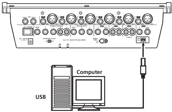
Connecting by USB
Use the included USB cable to connect the M-164UF with a computer as shown in the illustration.
CAUTION
Some USB equipment uses the USB bus frequently. In order to prevent the audio signal from dropping out, clicking noises and other trouble, we recommend that you do not connect other USB equipment (including USB hubs) to the same USB hub to which the M-164UF is connected. USB keyboards and mice are exceptions, however, and connecting them should not cause any problems.
Using Cubase LE4 to record
For details see the Cubase LE4 Quick Start Guide (page 4).
Related to mixer settings
Q: There is no sound from the speakers connected to the STEREO OUTPUTS jacks.
A:
Turn the MONITOR ST switch ON and check the MONITOR meters.
If the meter indicators are changing:
- Check the settings and volume of the connected amplification system.
If the meter indicators are not changing:
- Are the channel ST assign switches ON (pushed in)?
• Are the channel and ST faders raised? - Is the input sound source properly connected to the mixer?
Q: The sound is quiet even if the faders are raised.
A:
- If mics are being input to channels 1–6, are their TRIM knobs turned up?
- Are external sound sources connected to both the MIC and LINE input jacks of any of these channels (1–6)?
- If a condenser mic is connected, is phantom power ON?
Q: The sound is distorted.
A:
If the channel meters are peaking:
- Are the channel 1–6 TRIM knobs set suitably?
- Are the output levels of external sound sources connected to channels 7–16 too high?
If the channel meters display normal levels:
• Are the EQ settings too high?
- Are the channel or ST faders raised too high?
Q: The record player sounds strange.
A:
- Is it connected to channels 9-10, and is the PHONO ON switch ON?
- Is the record player grounding wire connected to the SIGNAL GND jack on the mixer?
Q: There is a humming noise coming from external equipment.
A:
- Try using grounding wire to connect a metal part of the external equipment chassis with the SIGNAL GND jack on the mixer.
Q: The internal effect does not work (M-164FX, M-164UF).
A:
- Have you increased the level of the AUX 2 knob for any channels with inputs to send their signals to the internal effect and increased the level of the AUX MASTER 2 knob?
- Have you raised the fader of the return channels selected by the INT. EFFECT RTN switch?
- If the return channels are set to 15-16, is something plugged into the STEREO IN jack, causing the effect return to be bypassed?
Q: There is no sound from the monitoring system connected to the AUX SEND 1 jack.
If you can monitor the AUX 1 bus by headphones:
- Check the settings of the external monitoring system.
If you cannot monitor the AUX 1 bus by headphones:
- Have you increased the level of the AUX 1 knob for any channels with inputs and increased the level of the AUX MASTER 1 knob?
- Are the PRE switches for the channels that you want to monitor ON? (If the PRE switches are OFF and the channel faders are lowered, those channels cannot be monitored.)
Related to recording with Cubase LE4 (M-164UF ONLY)
For details see the Cubase LE4 Quick Start Guide (page 4).
7 – Specifications and Block Diagrams
Ratings
Internal operation level: -2 dBu
Inputs
MIC input jacks (channels 1–6)
Connectors: XLR-3-31
Circuit type: electronically balanced (#1: ground, #2: hot, #3: cold)
Input impedance: 2.4 kΩ
Nominal input level (TRIM knob at maximum): -58 dBu
Nominal input level (TRIM knob at minimum): -12 dBu
Maximum input level: +10 dBu (TRIM knob at minimum)
LINE input jacks (channels 1–6)
Connectors: 3-pole standard jacks
Circuit type: electronically balanced (tip: hot, ring: cold, sleeve: ground)
Input impedance: 22 kΩ
Nominal input level (TRIM knob at maximum): -38 dBu
Nominal input level (TRIM knob at minimum): +8 dBu
Maximum input level: +30 dBu (TRIM knob at minimum)
7-8, 13-14 input jacks
Connectors: 3-pole standard jacks
Circuit type: electronically balanced (tip: hot, ring: cold, sleeve: ground)
Input impedance: 10 kΩ
Nominal input level: +4 dBu
Maximum input level: +22 dBu
9-10 input jacks
Connectors: RCA pin jacks
Circuit type: unbalanced
Input impedance: 47 kΩ (47 kΩ with PHONO ON)
Nominal input level: -10 dBV (-54 dBV with PHONO ON)
Maximum input level: +11 dBV
11-12 input jacks
Connectors: RCA pin jacks
Circuit type: unbalanced
Input impedance: 10 kΩ
Nominal input level: -10 dBV
Maximum input level: +11 dBV
15-16 input jacks
Connectors: 3-pole mini-jack (tip: L, ring: R, sleeve: ground)
Circuit type: unbalanced
Input impedance: 10 kΩ
Nominal input level: -10 dBV
Maximum input level: +11 dBV
Outputs
STEREO OUTPUTS (L, R) balanced jacks
Connectors: 3-pole standard jacks
Circuit type: electronically balanced (tip: hot, ring: cold, sleeve: ground)
Output impedance: 100 Ω
Nominal output level: +4 dBu
Maximum output level: +24 dBu
STEREO OUTPUTS (MONO) jacks
Connectors: 3-pole standard jacks
Circuit type: electronically balanced (tip: hot, ring: cold, sleeve: ground)
Output impedance: 100 Ω
Nominal output level: -2 dBu
Maximum output level: +20 dBu
STEREO OUTPUTS (L, R) unbalanced jacks
Connectors: RCA pin jacks
Circuit type: unbalanced
Output impedance: 100 Ω
Nominal output level: -10 dBV
Maximum output level: +6 dBV
SUB OUTPUTS (L, R) jacks
Connectors: 3-pole standard jacks
Circuit type: Pseudo balanced (tip: hot, ring: cold, sleeve: ground)
Output impedance: 150 Ω
Nominal output level: +4 dBu
Maximum output level: +20 dBu
SUB OUTPUTS (MONO) jacks
Connectors: 3-pole standard jacks
Circuit type: Pseudo balanced (tip: hot, ring: cold, sleeve: ground)
Output impedance: 150Ω
Nominal output level: -2 dBu
Maximum output level: +20 dBu
7 – Specifications and Block Diagrams
AUX SEND (1, 2) jacks
Connectors: 3-pole standard jacks
Circuit type: Pseudo balanced (tip: hot, ring: cold, sleeve: ground)
Output impedance: 150Ω
Nominal output level: +4 dBu
Maximum output level: +20 dBu
PHONES jack
Connector: 3-pole standard jack (tip: L, ring: R, sleeve: ground)
Maximum output: 45 mW + 45 mW (1% THD, for 32Ω load)
Performance
(Measured at a -2 dBu operating level)
Frequency response (MIC inputs → all outputs)
20 Hz – 20 kHz, +1/–3 dB (TRIM at maximum, for 150Ω load)
Distortion (MIC inputs → STEREO OUTPUTS)
0.01% or less (20 Hz – 20 kHz, TRIM at minimum)
Hum & noise (MIC inputs → STEREO OUTPUTS)
With 1 mic input: -60 dBu or more (TRIM at maximum)
With 6 mics input: -52 dBu or more (TRIM at maximum)
Crosstalk
-80 dB (1 kHz)
Other
Power:
AC adaptor (TASCAM PS-1225L)
AC adaptor input: AC 100–240 V, 50–60 Hz
AC adaptor output voltage: 12V DC
AC adaptor output electric current: 2.5 A
Power consumption:
25 W
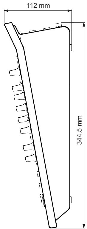
Dimensions:
390 (width) x 112 (height) x 344.5 (depth) mm
Weight:
3.3 kg (M-164), 3.4 kg (M-164FX), 3.5 kg (M-164UF)
NOTE
- Illustrations in this Owner's Manual might differ from the appearance of the actual product.
- In order to improve a product, its specifications and/or appearance might be changed without notice.
7 – Specifications and Block Diagrams
Dimensional drawing
7 – Specifications and Block Diagrams
Block diagram
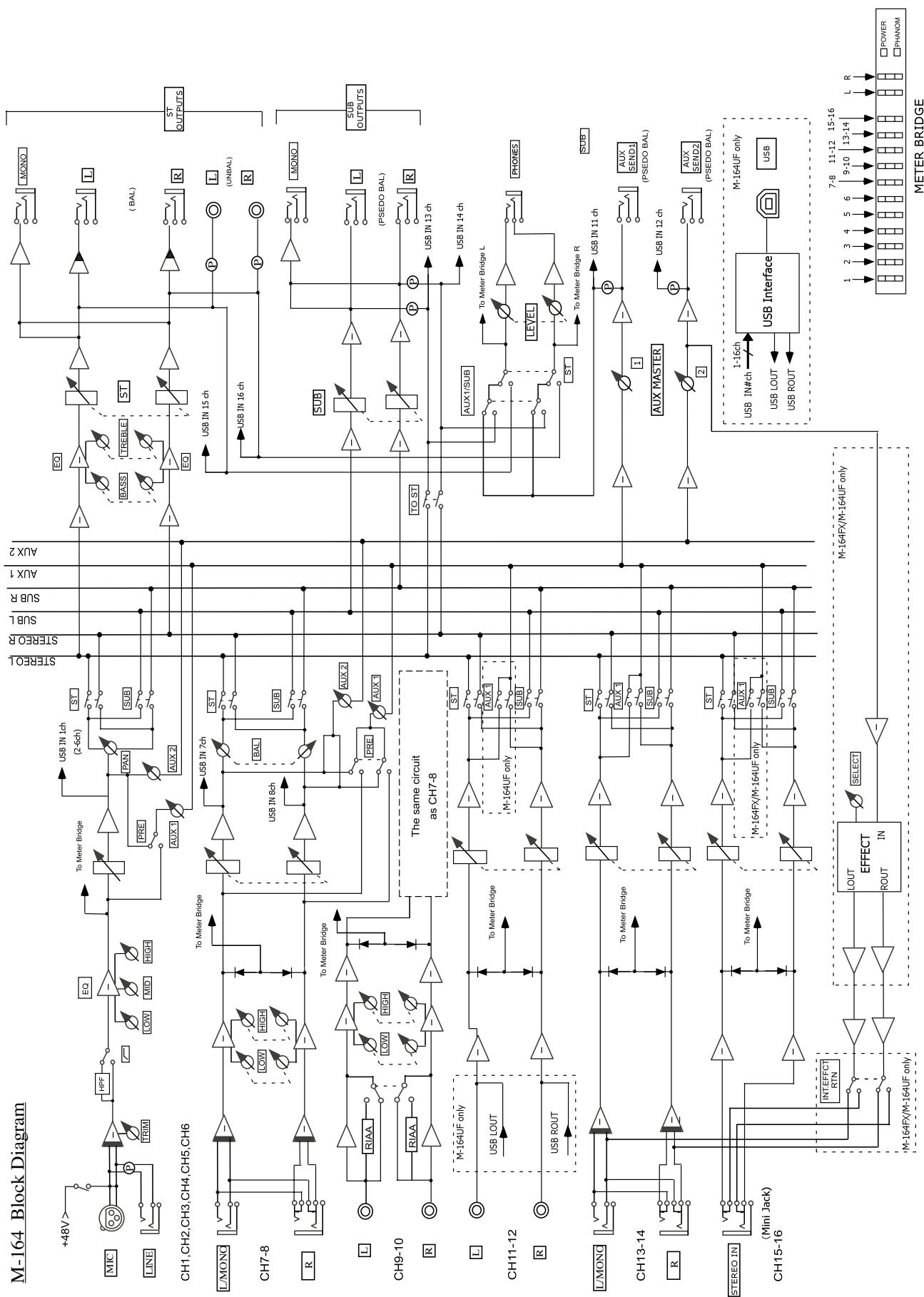
flowchart
graph TD
    subgraph "M-164 Block Diagram"
        direction TB
        A["+48V"] --> B["LMON"]
        B --> C["CH1,CH2,CH3,CH4,CH5,CH6"]
        C --> D["CH7-8"]
        D --> E["L/MON"]
        E --> F["CH9-10"]
        F --> G["CH11-12"]
        G --> H["L/MON"]
        H --> I["CH13-14"]
        I --> J["STEREO IN (Mini Jack)"]
        J --> K["CH15-16"]
    end

    subgraph "The same circuit as CH7-8"
        direction LR
        L["To Meter Bridge"] --> M["USB IN 7ch"]
        M --> N["USB IN 8ch"]
        N --> O["To Meter Bridge"]
        O --> P["USB LOUT"]
        P --> Q["USB ROUT"]
        Q --> R["M-164UF only"]

        S["To Meter Bridge"] --> T["USB IN 1ch (2-6ch)"]
        T --> U["ST"]
        U --> V["BASS"]
        V --> W["TREBLE"]
        W --> X["ST"]
        X --> Y["EQ"]
        Y --> Z["MONO"]

        T --> AA["AUX 1"]
        T --> AB["AUX 2"]
        T --> AC["AUX 3"]
        T --> AD["AUX 4"]

        V --> AE["BASS"]
        W --> AF["BASS"]
        X --> AG["BASS"]
        Y --> AH["BASS"]
        Z --> AI["ST"]
        AA --> AJ["(BAL)"]
        AB --> AK["(BAL)"]
        AC --> AL["ST OUTPUTS"]

        M --> AM["To Meter Bridge"]
        M --> AN["USB IN 15 ch"]
        M --> AO["USB IN 16 ch"]
        M --> AP["USB IN 13 ch"]
        M --> AQ["USB IN 14 ch"]

        N --> AR["AUX 2"]
        N --> AS["AUX 3"]
        N --> AT["AUX 4"]

        O --> AU["AUX 1"]
        O --> AV["AUX 2"]

        P --> AW["AUX 3"]
        P --> AX["AUX 4"]

        Q --> AY["AUX 1/2"]
        Q --> AZ["AUX 2/2"]

        S --> BA["AUX 1/2"]
        S --> BB["AUX 2/2"]

        T --> BC["AUX 3/3"]
        T --> BD["AUX 4/3"]

        U --> BE["AUX 1/2"]
        U --> BF["AUX 2/2"]

        V --> BG["AUX 3/3"]
        V --> BH["AUX 4/3"]

        W --> BI["AUX 1/2"]
        W --> BJ["AUX 2/2"]

        X --> BK["AUX 3/3"]
        X --> BL["AUX 4/3"]

        Y --> BM["AUX 1/2"]
        Y --> BN["AUX 2/2"]

        Z --> BO["AUX 3/3"]
        Z --> BP["AUX 4/3"]

        AA --> BQ["AUX 1/2"]
        AA --> BR["AUX 2/2"]

        AB --> BS["AUX 3/3"]
        AB --> BT["AUX 4/3"]

        AC --> BU["AUX 1/2"]
        AC --> BV["AUX 2/2"]

        AD --> BW["AUX 3/3"]
        AD --> BX["AUX 4/3"]

        AE --> BY["AUX 1/2"]
        AE --> BZ["AUX 2/2"]

        AF --> CA["AUX 3/3"]
        AF --> CB["AUX 4/3"]

        AG --> DA["AUX 1/2"]
        AG --> DB["AUX 2/2"]

        AH --> DC["AUX 3/3"]
        AH --> DD["AUX 4/3"]

        AI --> DJ["AUX 1/2"]
        AI --> DEA["AUX 2/2"]

        AJ --> DF["AUX 3/3"]
        AJ --> DG["AUX 4/3"]

        AK --> DH["AUX 1/2"]
        AK --> DIA["AUX 2/2"]

        AL --> DJ
        AL --> DEA
        AM --> DEA
    end

    subgraph "The same circuit as CH7-8"
            direction LR
            M_164UFonly["M-164UF only"]
            M_164UFonly -.-> M_164UFonly["M-164UF only"]
            M_164UFonly -.-> M_164UFonly["M-164UF only"]
            M_164UFonly -.-> M_164UFonly["M-164UF only"]
            M_164UFonly -.-> M_164UFonly["M-164UF only"]
            M_161UFonly["M-164UF only"]
            M_164UFonly -.-> M_164UFonly["M-164UF only"]
            M_164UFonly -.-> M_164UFonly["M-164UF only"]

    end

    subgraph "METER BRIDGE"
            direction LR
            USBInterface["USB Interface"]
            USBInterface -.-> USB-only["USB LOUT"]
            USBInterface -.-> USBROUT["USB ROUT"]
            USBInterface -.-> USBIN["USB IN#ch"]
            USBInterface -.-> USBINT["USB IN#ch"]
            USBInterface -.-> USBJ["USB IN#ch"]
            USBInterface -.-> USBK["USB IN#ch"]
            USBInterface -.-> USBL["USB IN#ch"]
            USBInterface -.-> USBM["USB IN#ch"]
            USBInterface -.-> USBN["USB IN#ch"]
            USBInterface -.-> USBO["USB IN#ch"]
            USBInterface -.-> USBP["USB IN#ch"]
            USBInterface -.-> USBQ["USB IN#ch"]
            USBInterface -.-> USBR["USB IN#ch"]
            USBInterface -.-> USBS["USB IN#ch"]
            USBInterface -.-> USBT["USB IN#ch"]
            USBInterface -.-> USBU["USB IN#ch"]
            USBInterface -.-> USBV["USB IN#ch"]
            USBInterface -.-> USBW["USB IN#ch"]
            USBInterface -.-> USBX["USB IN#ch"]
            USBInterface -.-> USBY["USB IN#ch"]
            USBInterface -.-> USBZ["USB IN#ch"]
            USBInterface -.-> USBX["USB IN#ch"]
            USBInterface -.-> USBY["USB IN#ch"]
            USBInterface -.-> USBZ["USB IN#ch"]
            USBInterface -.-> USBX["USB IN#ch"]
            USBInterface -.-> USBY["USB IN#ch"]
            USBInterface -.-> USBZ["USB IN#ch"]
            USBInterface -.-> USBX["USB IN#ch"]
            USB_Interface["USB Interface"]
            USB Interface -.-> USBOUT["USB LOUT"]
            USB Interface -.-> USBROUT["USB ROUT"]
            USB Interface -.-> USBIN["USB IN#ch"]
            USB Interface -.-> USBOUT["USB ROUT"]
            USB Interface -.-> USBX["USB IN#ch"]
            USB Interface -.-> USBY["USB IN#ch"]
            USB Interface -.-> USBZ["USB IN#ch"]
            USB Interface -.-> USBX["USB IN#ch"]
            USB Interface -.-> USBY["USB IN#ch"]
            USB Interface -.-> USBZ["USB IN#ch"]

    end
7 – Specifications and Block Diagrams
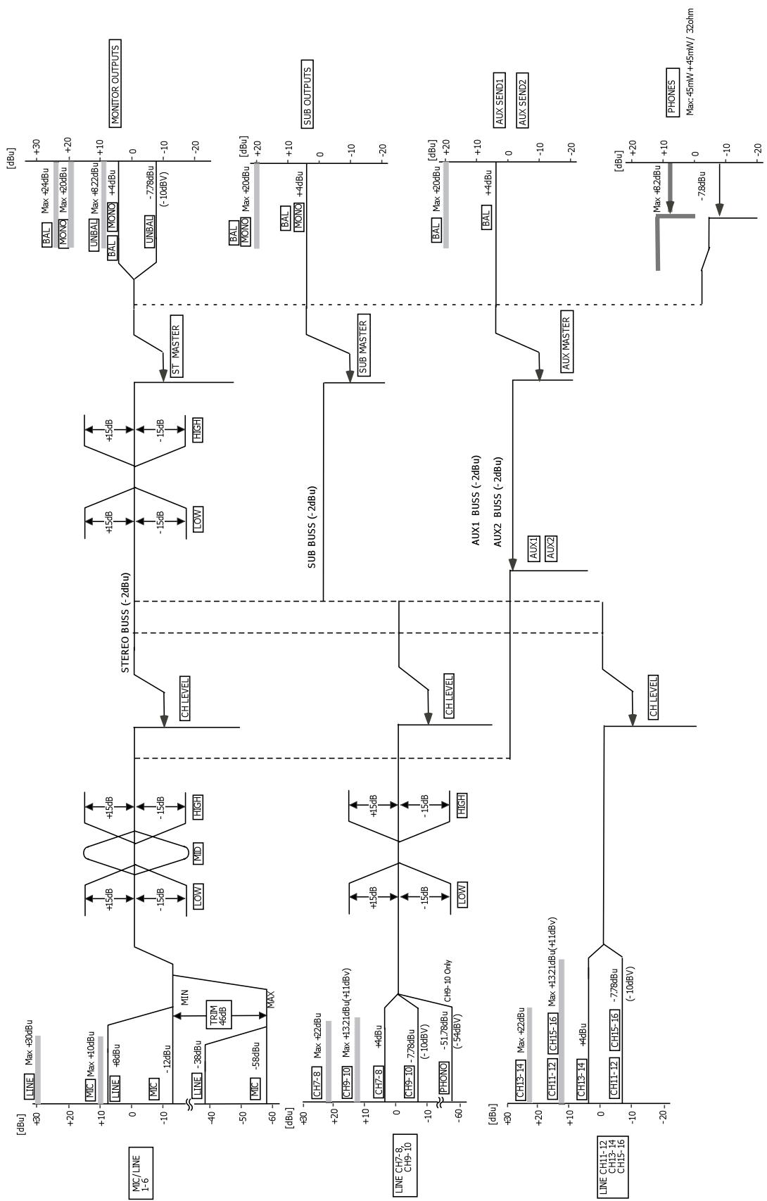
Level diagram
M-164/FX/UF Level Diagram
TASCAM®
TEAC PROFESSIONAL
M-164
TEAC CORPORATION
www.tascam.jp
Phone: +81-42-356-9143
1-47 Ochiai, Tama-shi, Tokyo 206-8530, Japan
TEAC AMERICA, INC.
www.tascam.com
Phone: +1-323-726-0303
7733 Telegraph Road, Montebello, California 90640 USA
TEAC CANADA LTD.
www.tascam.com
Phone: +1905-890-8008 Facsimile: +1905-890-9888
5939 Wallace Street, Mississauga, Ontario L4Z 1Z8, Canada
TEAC MEXICO, S.A. de C.V.
www.teacmexico.net
Phone: +52-55-5010-6000
Suites 19 & 20, Building 6, Croxley Green Business Park, Hatters Lane, Watford, Hertfordshire, WD18 8TE, UK
TEAC EUROPE GmbH
www.tascam.de
Phone: +49-611-71580

- TO THE USER
- CAUTION
- WARNING: TO PREVENT FIRE OR SHOCK HAZARD, DO NOT EXPOSE THIS APPLIANCE TO RAIN OR MOISTURE.
- For the customers in Europe
- WARNING
- IMPORTANT SAFETY INSTRUCTIONS
- - Introduction ...... 5
- – Names and Functions of Parts ...... 7
- – Preparation for Use...... 12
- – Using the mixer...... 18
- – Using with a Computer (M-164UF) 26
- – Troubleshooting......31
- – Specifications and Block Diagrams ... 32
- Main features
- Included items
- About this manual
- TIP
- - Introduction
- NOTE
- Trademarks
- Precautions and notes for placement and use
- Cleaning the unit
- ①\*\*USB indicator
- ② Input channel meters
- ③ MONITOR (L, R) meters
- ④ ⏻ indicator
- ⑤ +48V indicator
- ⑥ TRIM knobs (channels 1–6)
- ⑦ EQ section (channels 7-8, 9-10)
- - Names and Functions of Parts
- – Names and Functions of Parts
- ⑳ TO ST switch
- ⑲ TO AUX 1 switch(es)
- ⑳ SUB fader
- ③1 ST fader
- Rear panel
- – Preparation for Use
- Connecting the power
- Examples of connecting external equipment
- Precautions before making connections
- Making stereo output connections
- Connecting headphones
- Making input sound source connections
- Connecting mics
- Connecting synthesizers, other sound sources and audio equipment (line level sound sources)
- Channels 1–6
- Channels 7-8
- Channels 9-10
- Channels 11-12
- Channels 13-14
- Channels 15-16
- Setting the internal effects return channels (M-164FX and M-164UF)
- Turning the power on and putting the mixer in standby
- Before turning the power on
- Turning on the power
- Putting the mixer in standby
- Adjusting levels
- Raise the channel fader.
- Using the mixer channel functions
- High-pass filter (HPF)
- EQ
- - Using the mixer
- AUX sends
- AUX 1
- AUX 2
- Monitoring with headphones
- Using AUX 1 for a monitoring mix
- Using sub-group functions
- Using the internal effects (M-164FX and M-164UF)
- Select the input channel for the return signal.
- Turn the ST switch ON for the input channel receiving the return signal, and use its fader to adjust return levels.
- Using external effects
- Using a record player
- Making final adjustments to the main output sound
- – Using with a Computer (M-164UF)
- Functions
- Installation
- System requirements
- Windows
- Supported operating system:
- Recommended system:
- Mac OS X
- Installing the drivers
- Installing the drivers for Windows
- Installation procedures
- Installation of Mac OS X drivers
- How to update the firmware
- Updating the firmware with Windows
- Updating the firmware with Macintosh (OS X)
- Computer settings
- Control panel settings
- Overview
- Driver settings
- Audio Performance (Windows OS)
- Connecting by USB
- Using Cubase LE4 to record
- Related to mixer settings
- Related to recording with Cubase LE4 (M-164UF ONLY)
- – Specifications and Block Diagrams
- Ratings
- Inputs
- MIC input jacks (channels 1–6)
- LINE input jacks (channels 1–6)
- 7-8, 13-14 input jacks
- 9-10 input jacks
- 11-12 input jacks
- 15-16 input jacks
- Outputs
- STEREO OUTPUTS (L, R) balanced jacks
- STEREO OUTPUTS (MONO) jacks
- STEREO OUTPUTS (L, R) unbalanced jacks
- SUB OUTPUTS (L, R) jacks
- SUB OUTPUTS (MONO) jacks
- AUX SEND (1, 2) jacks
- PHONES jack
- Performance
- Frequency response (MIC inputs → all outputs)
- Distortion (MIC inputs → STEREO OUTPUTS)
- Hum & noise (MIC inputs → STEREO OUTPUTS)
- Crosstalk
- Other
- Power:
- Power consumption:
- Dimensions:
- Weight:
- # 1
- # 2
- # 3
- # 4
- # 5
- # 6
- # 7
- # 8
- # 9
- # 10
- # 11
- # 12
- # 13
- # 14
- # 15
- # 16
- # 17
- # 18
- # 19
- # 20
- # 21
- # 22
- # 23
- # 24
- # 25
- # 26
- # 27
- # 28
- # 29
- # 30
- # 31
- # 32
- # 33
- # 34
- # 35
- # 36
- # 37
- # 38
- # 39
- # 40
- # 41
- # 42
- # 43
- # 44
- # 45
- # 46
- # 47
- # 48
- # 49
- # 50
- # 51
- # 52
- # 53
- # 54
- # 55
- # 56
- # 57
- # 58
- # 59
- # 60
- # 61
- # 62
- # 63
- # 64
- # 65
- # 66
- # 67
- # 68
- # 69
- # 70
- # 71
- # 72
- # 73
- # 74
- # 75
- # 76
- # 77
- # 78
- # 79
- # 80
- # 81
- # 82
- # 83
- # 84
- # 85
- # 86
- # 87
- # 88
- # 89
- # 90
- # 91
- # 92
- # 93
- # 94
- # 95
- # 96
- # 97
- # 98
- # 99
- #100
- Level diagram
- TASCAM®
- TEAC PROFESSIONAL
- M-164
Brand : TASCAM
Model : M-164FX
Category : Mixer