LR16 - Mixing console FOSTEX - Free user manual and instructions
Find the device manual for free LR16 FOSTEX in PDF.

User questions about LR16 FOSTEX
0 question about this device. Answer the ones you know or ask your own.
Ask a new question about this device
Download the instructions for your Mixing console in PDF format for free! Find your manual LR16 - FOSTEX and take your electronic device back in hand. On this page are published all the documents necessary for the use of your device. LR16 by FOSTEX.
USER MANUAL LR16 FOSTEX
You can upgrade the software yourself. See page 80 for details about how to upgrade the software.

CAUTION
RISK OF ELECTRIC SHOCK DO NOT OPEN

CAUTION: TO REDUCE THE RISK OF ELECTRIC SHOCK,
DO NOT REMOVE COVER (OR BACK).
NO USER - SERVICEABLE PARTS INSIDE.
REFER SERVICING TO QUALIFIED SERVICE PERSONNEL.
"WARNING"
"TO REDUCE THE RISK OF FIRE OR ELECTRIC SHOCK, DO NOT EXPOSE THIS APPLIANCE TO RAIN OR MOISTURE."
SAFETY INSTRUCTIONS
- Read Instructions - All the safety and operating instructions should be read before the appliance is operated.
- Retain Instructions - The safety and operating instructions should be retained for future reference.
- Heed Warnings - All warnings on the appliance and in the operating instructions should be adhered to.
- Follow Instructions - All operating and use instructions should be followed.
- Water and Moisture - The appliance should not be used near water - for example, near a bathtub, washbowl, kitchen sink, laundry tub, in a wet basement, or near a swimming pool, and the like.
- Carts and Stands - The appliance should be used only with a cart or stand that is recommended by the manufacturer.

An appliance and cart combination should be moved with care. Quick stops, excessive force, and uneven surfaces may cause the appliance and cart combination to overturn.
- Wall or Ceiling Mounting - The appliance should be mounted to a wall or ceiling only as recommended by the manufacturer.
- Ventilation - The appliance should be situated so that its location or position dose not interfere with its proper ventilation. For example, the appliance should not be situated on a bed, sofa, rug, or similar surface that may block the ventilation openings; or, placed in a built-in installation, such as a bookcase or cabinet that may impede the flow of air through the ventilation openings.
- Heat - The appliance should be situated away from heat sources such as radiators, heat registers, stoves, or other appliances (including amplifiers) that produce heat.
- Power Sources - The appliance should be connected to a power supply only of the type described in the operating instructions or as marked on the appliance.
- Grounding or Polarization - The precautions that should be taken so that the grounding or polarization means of an appliance is not defeated.
CAUTION:
TO PREVENT ELECTRIC SHOCK, MATCH WIDE BLADE OF PLUG TO WIDE SLOT, FULLY INSERT.
ATTENTION:
POUR ÉVITER LES CHOCS ÉLECTRIQUES, INTRODUIRE LA LAME LA PLUS LARGE DE LA FICHE DANS LA BORNE CORRESPONDANTE DE LA PRISE ET POUSSER JUSQU' AU FOND.

The lightning flash with arrowhead symbol, within an equilateral triangle, is intended to alert the user to the presence of uninsulated "dangerous voltage" within the product's enclosure that may be of sufficient magnitude to constitute a risk of electric shock to persons.

The exclamation point within an equilateral triangle is intended to alert the user to the presence of important operating and maintenance (servicing) instructions in the literature accompanying the appliance.
- Power Cord Protection - Power supply cords should be routed so that they are not likely to be walked on or pinched by items placed upon or against them, paying particular attention to cords at plugs, convenience receptacles, and the point where they exit from the appliance.
- Cleaning - The appliance should be cleaned only as recommended by the manufacturer.
- Nonuse Periods - The power cord of the appliance should be unplugged from the outlet when left unused for a long period of time.
- Object and Liquid Entry - Care should be taken so that objects do not fall and liquids are not spilled into the enclosure through openings.
- Damage Requiring Service - The appliance should be serviced by qualified service personnel when:
A. The power supply cord or the plug has been damaged; or
B. Objects have fallen, or liquid has been spilled into the appliance; or
C. The appliance has been exposed to rain; or
D. The appliance does not appear to operate normally or exhibits a marked change in performance; or
E. The appliance has been dropped, or the enclosure damaged. - Servicing - The user should not attempt to service the appliance beyond that described in the operating instructions. All other servicing should be referred to qualified service personnel.
- The appliance should be situated away from drops of water or spray of water.
- Objects containing liquid such as vase must not be put on the appliance.
- The appliance is not completely isolated from the power supply even if the power switch is at off position.
- Apparatus shall not be exposed to dripping or splashing and no objects filled with liquids, such as vases, shall be placed on the apparatus.
- Only use attachments/accessories specified by the manufacturer.
- An appliance with a protective earth terminal should be connected to a mains outlet with a protective earth connection.
- An appliance should be placed in a position where an AC plug / inlet can be easily pulled out by hand.
- Main plug is used as the disconnection device. It shall remain readily operable and should not be obstructed during intended use. To be completely disconnected the apparatus from supply mains, the mains plug of the apparatus shall be disconnected from the mains socket outlet completely.
Important Safety Instructions
1) Read these instructions.
2) Keep these instructions.
3) Heed all warnings.
4) Follow all instructions.
5) Do not use this apparatus near water.
6) Clean only with dry cloth.
7) Do not block any ventilation openings. Install in accordance with the manufacturer's instructions.
8) Do not install near any heat sources such as radiators, heat registers, stoves, or other apparatus (including amplifiers) that produce heat.
9) Do not defeat the safety purpose of the polarized or grounding-type plug. A polarized plug has two blades with one wider than the other. A grounding type plug has two blades and a third grounding prong. The wide blade or the third prong are provided for your safety. If the provided plug does not fit into your outlet, consult an electrician for replacement of the obsolete outlet.
10) Protect the power cord from being walked on or pinched particularly at plugs, convenience receptacles, and the point where they exit from the apparatus.
11) Only use attachments/accessories specified by the manufacturer.
12) Use only with the cart, stand, tripod, bracket, or table specified by the manufacturer, or sold with the apparatus. When a cart is used, use caution when moving the cart/apparatus combination to avoid injury from tip-over.

13) Unplug this apparatus during lightning storms or when unused for long periods of time.
14) Refer all servicing to qualified service personnel. Servicing is required when the apparatus has been damaged in any way, such as power-supply cord or plug is damaged, liquid has been spilled or objects have fallen into the apparatus, the apparatus has been exposed to rain or moisture, does not operate normally, or has been dropped.
15) Excessive sound pressure from earphones and headphones can cause hearing loss.
Table of contents
Safety instructions ....2
Introduction 9
About power supply 9
Precautions in installation 9
Notes on handling the internal hard disk drive ....9
About version upgrade....10
Condensation ....10
Cleaning the exterior ....10
About copyrights ....10
About damage ....10
Overview 11
Main features ....11
Mixer section (control unit) features ....11
Recorder section (main unit) features ....17
Before using the unit ....13
Unpacking the carton ....13
Usage examples of LR16 ....14
Integrating the control unit and main unit ....15
Preparation of power supply 17
Connecting the power cord ....17
Turning on the power ....17
Procedures of turning on the power after connecting peripheral devices ....17
Procedures of turning off the power after connecting peripheral devices ....17
Connection to external devices ....18
Connection example (live recording)....18
Connection example (home recording) 19
Balanced and unbalanced inputs/outputs 20
Names and functions ......21
Control unit (input channel 1 through 16)....22
Control unit (master channel) 24
Control unit (rear panel) 27
Main unit (front panel) 27
Main unit (rear panel) 29
Display details ....30
HOME screen ....30
MENU mode screen ....31
Memory play setup mode screen ....31
Mixer functions (Mixer basics) 34
Signal flow of the mixer ....34
Connecting sources ....35
Connecting sources to the input connectors ....35
Phantom power supply setting 35
Selecting channel source ....35
Adjusting the input level 35
Low-cut filter 36
Limiter 36
Equalizer ....36
EQ HIGH 37
EQ MID 37
EQLO 37
Using an external effect processor ....37
Using AUX 1, 2 and 3 ....37
Using Insert 38
Using the internal effects processor ....38
Applying the internal effects ....38
About the effect types ....39
Monitoring ....39
Solo monitor ....40
Channel grouping ....40
Using SUB IN ....41
Block diagram 42
Recorder functions (Recording/Playback) 43
The basics of the recorder ....44
Recording types ....44
Recording modes 45
Project 45
Live recording ....46
Preparation of recording ....48
Adjusting recording level of each channel ....48
Adjusting output level of the stereo L/R bus ....49
Performing recording ....49
Playback of the project ....50
Multitrack recording ....51
Overdubbing 51
Mixdown 52
Punch in/out ....54
Punch in/out using the keys ....54
Punch in/out using the footswitch 55
Recorder functions (Memory play) 57
Setting on the memory play setup screen ....58
Assigning stereo mix files ....58
Selecting a channel pair for memory play ....59
Selecting the memory play mode ....59
Performing memory play 60
Recorder functions (Mark function) 61
Adding a mark....61
Adding a mark on-the-fly 61
Adding a mark via the mark list screen 61
Locating to a mark point 62
Editing a mark 62
Editing a mark label 62
Editing a mark position....63
Deleting a mark 64
Recorder functions (Project management) 65
Selecting a project 65
Creating a new project ....65
Editing a project name ....66
Rolling back a project ....67
Saving a project to an external medium ....68
Copying a stereo mix file to an external medium ....70
Protecting a project ....72
Deleting a project ....72
Recorder functions (File transfer to/from a computer) 74
Connecting the LR16 to a personal computer ....74
Enabling USB connection ....74
Copying data from the LR16 to a computer ....76
Copying data from a computer to the LR16 76
Recorder functions (Other functions) 77
Adjusting the display contrast ....77
Selecting the footswitch function ....77
Formatting the internal hard disk....78
Initializing the system memory ....78
Assigning the destinations of SUB IN and the memory play signals ....79
To assign the destination channels of SUB IN ....79
To assign the destination channels of Memory play 80
Software version upgrade ....80
MIDI synchronization 82
Setting frame rate 82
Setting FS/Bit of project 83
Specifications 84
Inputs/Outputs 84
Recording/Playback 84
General 85
Physical dimensions 85
MIDI Implementation Chart ....86
Declaration of EC Directive 87
FOSTEX AMERICA LIMITED WARRANTY 88
INDEX 90
Introduction
Thank you very much for purchasing the Model LR16.
The LR16 is a live recording mixer which consists of the control unit which is equipped with a digital mixer and the main unit which is equipped with a recorder and I/O connectors.
To ensure the best performance, read this manual thoroughly before using the LR16. Keep this manual handy for future reference.
About power supply
- Be sure to connect the LR16 to the power supply specified in the specifications section of this owner's manual. Do not use an AC outlet of any other voltage.
- Do not connect the LR16 to the same AC outlet to which devices that could generate noise (such as a large motor or dimmer), or the devices that consume a large amount of power (such as an air conditioning system or large electric heater) are connected.
- If you use the LR16 in an area with a different power voltage, first consult your dealer or the nearest Fostex service station. You can use the LR16 with a power frequency of 50Hz or 60Hz.
- It is very dangerous to use a power cord that is frayed or damage. In such a case, stop using the LR16 immediately and ask your dealer to repair the cord.
- To avoid possible electric shock and damage to the LR16, avoid contact with water or other liquids, or do not handle the power plug while your hands are wet.
- To prevent possible electric shock and damage to the LR16, do not remove the main unit cover or reach the inside the LR16.
- Do not let water or other liquid, or metal objects such as pins, accidentally enter the inside of the LR16 because this may lead to electric shock or damage.
Should water enter the inside of the LR16, remove the power plug from AC outlet, and consult your dealer or the nearest Fostex service station.
- To prevent damage to the LR16, be sure to power on the connected devices first, then turn on the power to the LR16. When you remove or connect the cables to the input/output connectors on the LR16, make sure that the channel and master faders and volume controls are set “∞”.
Precautions on installation
- Do not install the unit in the following conditions.
* In an extremely hot or cold place
* In a moist place
* In a vibrated place
* In a dusty place
* In a strong magnetic field or near a device which generates a magnetic field
* In the direct sunshine
* In the direct shower or rain
- To integrate the main unit and control unit or mount them to a rack, follow the instruction described in this manual (note that screws for rack mounting are not supplied with the LR16).
Notes on handling the internal hard disk drive
- A hard disk drive for recording/playback is built in the recorder section of the main unit. When you move or install the LR16, Do not apply mechanical shock or drop the unit.
When you install the main unit and control unit separately, wire the CAT-5 cable between these units with care to avoid catching the cable with your foot.
- You can format the internal hard disk drive via the MENU mode. For details, see "Formatting the internal hard disk drive" on page 78.
About version upgrade
- The software of the LR16 will be upgraded in the future. You can download the latest software from our website and upgrade the LR16 yourself. For details about how to upgrade the LR16 to the latest software version, see page 80.
Condensation
- When temperature and humidity change suddenly (for example, when you move the LR16 from a cold place to a warm place), moisture condensation may occur to the drive, display and panel. In such a case, leave it with the power turned off for some time until the moisture evaporates.
Cleaning the exterior
- For normal cleaning, use a soft dry cloth. For stubborn dirt, moisten a cloth in diluted detergent, wring it out firmly, and wipe the dirt off. Then polish with a dry cloth. Never use solvents such as alcohol, thinner or benzene, since these will damage the printing and finish of the exterior.
About copyrights
- It is prohibited by law to use any part of a CD recording or video images or audio data for which copyright is possessed by a third party for commercial purposes such as contents, broadcasts, sales, or distribution-any purpose other than for your personal pleasure.
About damage
- Fostex is not responsible for any “direct damage” or “indirect damage” caused by using the LR16.
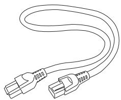
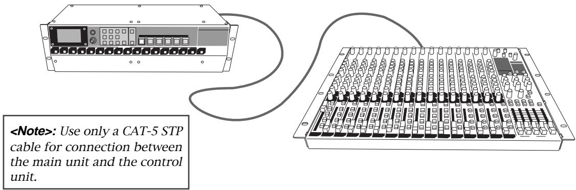
About CAT-5 cable
- Use only a CAT-5 STP cable for connection between the main unit and the control unit.
Overview
The Model LR16 consists of the control unit which is equipped with a digital mixer with intuitive analog like operation and the main unit which is equipped with a recorder and I/O connectors. You can install the LR16 flexibly by integrating these units, mounting them on a rack or setting them away from each other (up to 50 meter distance using a CAT-5 cable).
The LR16 is an ideal tool for schools, houses of worship, clubs, coffee houses, project studios, mobile recording, rental sound/recording, etc.
This cable can be used when installing the LR16 by integrating the control and main units. To mount them on a rack or set them away from each other, prepare an appropriate CAT-5 cable which has enough length (up to 50 m).
Main features
Mixer section (control unit) features
- Digitally controlled trim on each input channel, allowing optimum input level adjustment for each mic/line input.
- Fostex originally-developed digital effect unit (reverb/delay) is built in, allowing selection from 12 effect types.
- Provides 16 input faders, four group faders and stereo master fader, allowing analog like operation.
• 3-band (High/Mid/Low) input equalizer on each input channel.
- Insertion point on input channel 1 through 8, allowing connection to an external comp/limiter, etc.
- XLR-phone combo type connector provided on each input channel, allowing mic or line connection. In addition, phantom power can be supplied to each XLR connector, allowing use of a condenser microphone. (You can turn on or off phantom power in eight channel groups.)
• Four group outputs allow connection to an external mixer or multitrack recorder.
- Aux and effect sends allow connection to an external effect unit, a stage monitor system, etc.
Recorder section (main unit) features
- Built in a large capacity hard disk drive which allows up to 16 track digital recording (approx. 16 hour recording in 44.1 kHz/16 bit, 80GB).
- In addition to up to 16 track recording, stereo mix recording is possible. Also, multitracks and stereo mix can be recorded simultaneously.
• Mark function allows locating to a mark. - 132 x 64 dot graphic LCD allows viewing the level meters and information at a glance.
- Memory play function is provided, allowing instant playback using the numeric keys as well as a footswitch (the footswitch function can be selected using the System menu of the MENU mode).
- Punch in/out function using the panel keys as well as a footswitch.
- By connecting a computer to the [USB PC] port, you can transfer audio files (note that you cannot simultaneously use the [USB HOST] port).
- By connecting a FAT16 and FAT32 formatted USB flash memory stick, you can copy audio files or version upgrade file.
- From the [MIDI OUT] port, MTC (MIDI Time Code) can be output, allowing synchronization with external MIDI devices (the MTC frame rate can be selected between 25 fps and 30 fps via the System menu of the MENU mode).
Before using the unit
Read this chapter carefully before using the unit.
Unpacking the carton
Unpack the carton and inspect the contents for damage or shortages.
The following contents should be found in the carton. If you find any damage or shortages, contact your Fostex dealer.
Main unit (including recorder section and I/O connector sections) x 1
natural_image
Front view diagram of a rack-mounted server unit with control panel and drive buttons (no text or labels)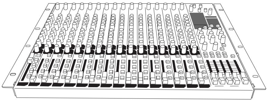
natural_image
Technical line drawing of a multi-panel electronic device with cylindrical connectors and a central component (no text or symbols)Controller unit x 1
natural_image
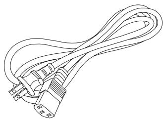
Line drawing of a coiled electrical plug with two terminal connectors (no text or symbols)Power cord x 1
natural_image
Line drawing of a U-shaped electrical outlet with two connectors (no text or symbols)CAT-5 STP cable (approx. 50 cm) x 1

natural_image
Illustration of a closed book labeled 'Fostex' (no additional text or symbols visible)Operation manual x 1
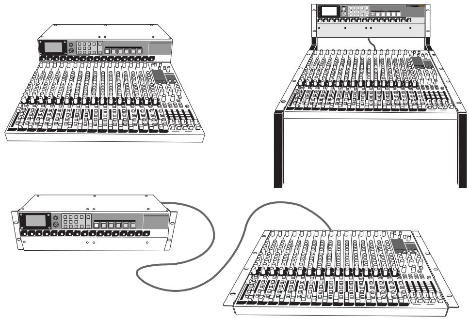
Usage examples of LR16
The control unit and main unit of the LR16 are separated. You can set these units flexibly.
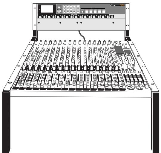
Integrating the main unit and control unit.
You can integrate the main unit and control unit.
Use the supplied CAT-5 cable (approx. 50 cm length) to connect between the units. See the next page for details about how to integrate the units.
natural_image
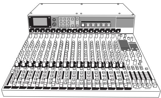
Line drawing of a multi-compartment audio workstation with knobs and control panels (no text or labels)Mounting the main unit and control unit on the rack.
As shown on the right, you can mount each unit to the rack. In this case, use a CAT-5 cable which has enough length for connecting between the units (the cable supplied with the LR16 is approximately 50 cm length).
natural_image
Line drawing of a audio workstation with multiple audio jack knobs and a front panel (no text or labels visible)Setting the main unit and control unit separately.
You can set the main unit and control unit over a 50 meter distance. In such a case, use a CAT-5 cable which has enough length for connecting between the units (the cable supplied with the LR16 is approximately 50 cm length).
text_image
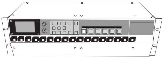
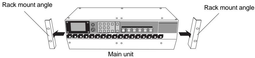
Integrating the control unit and main unit
Follow the procedure below to integrate the control unit and main unit.
- Phillips-head screwdriver (which matches the fixing screws for rack mounting)
- The supplied CAT-5 cable
(1) Remove the rack mount angles attached to the side panels of each unit.
The removed rack mount angles and fixing screws are used in step (3) below, so be careful not to lose them.
text_image
Rack mount angle Main unit Rack mount angle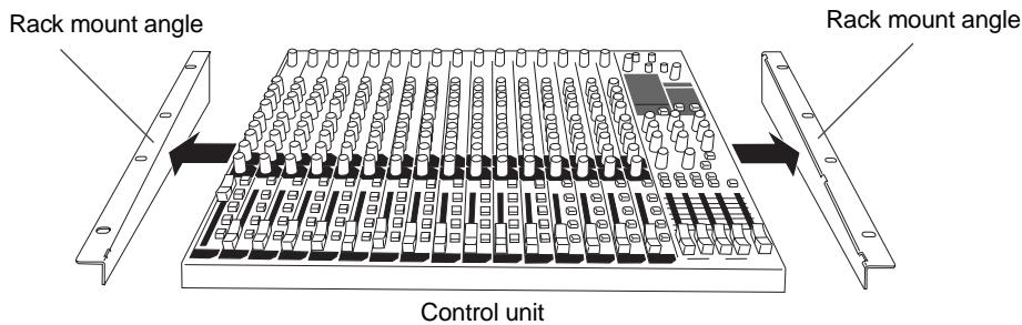
text_image
Rack mount angle Control unit Rack mount angle(2) Connect the [ETHER] connector of the control unit and the [CONTROLLER] connector of the main unit using the supplied CAT-5 cable.
The cable should run through the cable guides fixed near the connectors of the both units (see below).
When you connect or disconnect a CAT-5 cable, make sure that the LR16 is powered off.
![FOSTEX LR16 - Connect the [ETHER] connector of the control unit and the [CONTROLLER] connector of the main unit using the supplied CAT-5 cable. - 1](/content/2025/01/168456/images/d8f3bca03a8d25c7745f93856a912d06a6114f125087c1178bb30be77b5225e5.jpg)
text_image
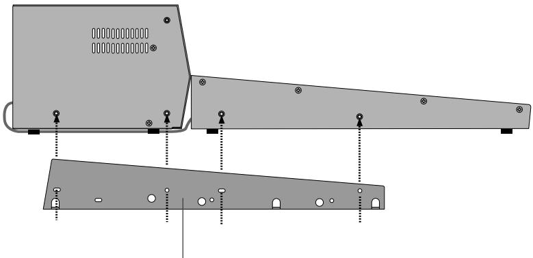
CONTROLLER Main unit Control unit(3) Using the rack mount adaptors removed from the control unit, fix the control unit and main unit.
Attach the rack mount adaptors to the both left and right sides in the direction shown below. Use four screws for each side.
natural_image
Technical diagram of a mechanical component with mounting holes and structural ribs (no text or symbols)Rack mount adaptor
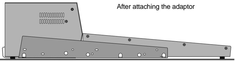
text_image
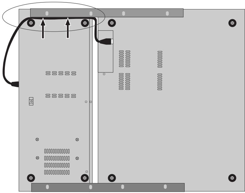
After attaching the adaptor(4) Put the CAT-5 cable into the space between the rubber feet and mounting bracket (indicated by arrows below).
The space between the rubber feet and mounting bracket is narrow, so be careful not to damage the cable when you put it into the space.
natural_image
Diagram of a computer drive bay with cable and socket, showing internal components and mounting points (no text or symbols)Preparation of power supply
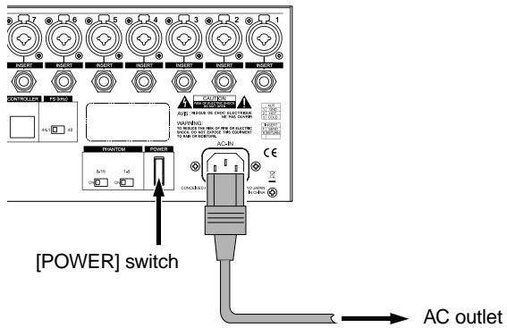
Connecting the power cord
Using the supplied power cord, connect the [AC IN] connector on the rear panel of the main unit and the AC outlet.
text_image
[POWER] switch AC outletTurning on the power
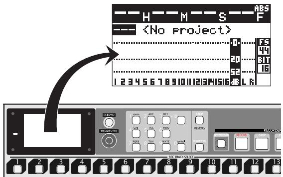
Press down the [POWER] switch on the rear panel of the main unit to turn on the power.
After a while, the LR16 normally starts up and the display on the recorder unit shows "
For details about recording, see "Mixer function" on page 33 and "Recorder function" on page 43.
text_image
ABS H M S FTo turn on or off the LR16 and peripheral devices which are connected to the LR16, follow the proper procedures described below.
Procedures of turning on the power after connecting peripheral devices
(1) Turn on the devices connected to the [INPUT] connectors to the LR16.
(2) Turn on the LR16.
(3) Turn on the monitor amplifier (or powered monitor speaker).
Procedures of turning off the power after connecting peripheral devices
(1) Turn off the monitor amplifier (or powered monitor speaker).
(2) Turn off the LR16.
(3) Turn off the devices connected to the [INPUT] connectors to the LR16.
Connection to external devices
Connection example (live recording)
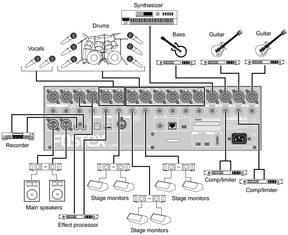
flowchart
graph TD
    A["Synthesizer"] --> B["Vocals"]
    A --> C["Drums"]
    A --> D["Bass"]
    A --> E["Guitar"]
    A --> F["Guitar"]
    A --> G["Recorder"]
    A --> H["Main speakers"]
    A --> I["Effect processor"]
    A --> J["Stage monitors"]
    A --> K["Stage monitors"]
    A --> L["Comp/limiter"]
    A --> M["Comp/limiter"]
    A --> N["FOSTEX LRIE LIVE RECORDING METER"]
    B --> O["Group (40Hz)"]
    C --> P["USB"]
    D --> Q["FOOT SW CONTROLLER PANEL LOCK"]
    E --> R["INSERT INSERT INSERT INSERT"]
    F --> S["PHANTOM POWER"]
    G --> T["Stage monitors"]
    H --> U["Stage monitors"]
    I --> V["Stage monitors"]
    J --> W["Stage monitors"]
    K --> X["Stage monitors"]
    L --> Y["Stage monitors"]
    M --> Z["Stage monitors"]
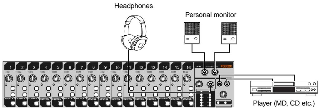
text_image
Headphones Personal monitor 1 2 3 4 5 6 7 8 9 10 11 12 13 14 15 16 LRIG FOSTEX SOURCE SOURCE SOURCE SOURCE SOURCE SOURCE SOURCE SOURCE SOURCE SOURCE SOURCE SOURCE SOURCE SOURCE SOURCE SOURCE SOURCE SOURCE SOURCE SOURCE SOURCE SOURCE SOURCE SOURCE SOURCE SOURCE SOURCE SOURCE SOURCE SOURCE SOURCE SOURCE SOURCE SOURCE SOURCE SOURCE SOURCE SOURCE SOURCE SOURCE SOURCE SOURCE SOURCE SOURCE SOURCE SOURCE SOURCE SOURCE SOURCE SOURCE SOURCE SOURCE SOURCE SOURCE SOURCE SOURCE SOURCE SOURCE SOURCE SOURCE SOURCE SOURCE SOURCE SOURCE SOURCE SOURCE SOURCE SOURCE SOURCE SOURCE SOURCE SOURCE SOURCE SOURCE SOURCE SOURCE SOURCE SOURCE SOURCE SOURCE SOURCE SOURCE SOURCE SOURCE SOURCE SOURCE SOURCE SOURCE SOURCE SOURCE SOURCE SOURCE SOURCE SOURCE SOURCE SOURCE SOURCE SOURCE SOURCE SOURCE SOURCE NAME Player (MD, CD etc.)Connection example (home recording)
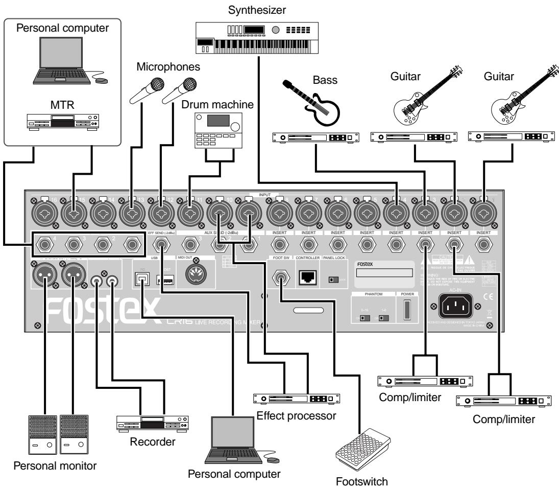
flowchart
graph TD
    A["Personal computer"] --> B["MTR"]
    B --> C["Synthesizer"]
    C --> D["Microphones"]
    C --> E["Drum machine"]
    D --> F["Bass"]
    E --> G["Guitar"]
    E --> H["Guitar"]
    F --> I["FoSTEX"]
    G --> J["Guitar"]
    H --> K["Guitar"]
    I --> L["VOU"]
    J --> M["VOU"]
    K --> N["VOU"]
    L --> O["USB"]
    M --> P["USB"]
    N --> Q["RESET"]
    O --> R["RESET"]
    P --> S["RESET"]
    Q --> T["RESET"]
    R --> U["RESET"]
    S --> V["RESET"]
    T --> W["RESET"]
    U --> X["RESET"]
    V --> Y["RESET"]
    W --> Z["RESET"]
    X --> AA["RESET"]
    Y --> AB["RESET"]
    Z --> AC["VOU"]
    AA --> AD["VOU"]
    AB --> AE["VOU"]
    AC --> AF["VOU"]
    AD --> AG["VOU"]
    AE --> AH["VOU"]
    AF --> AI["VOU"]
    AG --> AJ["VOU"]
    AH --> AK["VOU"]
    AI --> AL["VOU"]
    AJ --> AM["VOU"]
    AK --> AN["VOU"]
    AL --> AO["VOU"]
    AM --> AP["VOU"]
    AN --> AQ["VOU"]
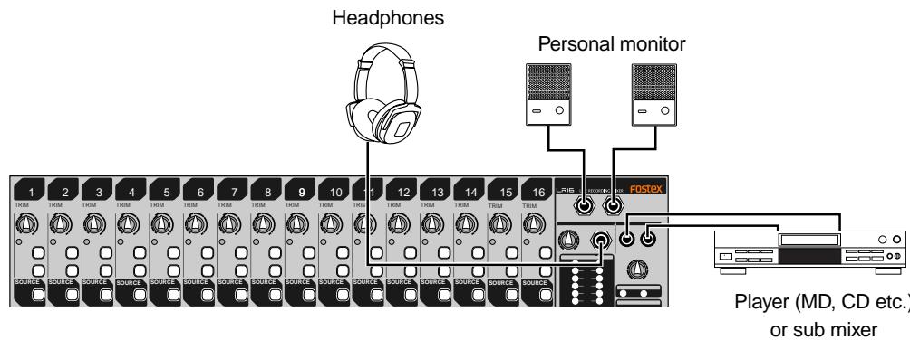
text_image
Headphones Personal monitor 1 2 3 4 5 6 7 8 9 10 11 12 13 14 15 16 TRIM TRIM TRIM TRIM TRIM TRIM TRIM TRIM TRIM TRIM TRIM TRIM TRIM TRIM TRIM TRIM TRIM TRIM TRIM TRIM TRIM TRIM TRIM TRIM TRIM TRIM TRIM TRIM TRIM TRIM TRIM TRIM TRIM TRIM TRIM TRIM TRIM TRIM TRIM TRIM TRIM TRIM TRIM TRIM TRIM TRIM TRIM TRIM TRIM TRIM TRIM SOURCE SOURCE SOURCE SOURCE SOURCE SOURCE SOURCE SOURCE SOURCE SOURCE SOURCE SOURCE SOURCE SOURCE SOURCE SOURCE SOURCE SOURCE SOURCE SOURCE SOURCE SOURCE SOURCE SOURCE SOURCE SOURCE SOURCE SOURCE SOURCE SOURCE SOURCE SOURCE SOURCE SOURCE SOURCE SOURCE SOURCE SOURCE SOURCE SOURCE SOURCE SOURCE SOURCE SOURCE SOURCE SOURCE SOURCE SOURCE SOURCE SOURCE SOURCE SOURCE SOURCE SOURCE SOURCE SOURCE SOURCE SOURCE SOURCE SOURCE SOURCE SOURCE SOURCE SOURCE SOURCE SOURCE SOURCE SOURCE SOURCE SOURCE SOURCE SOURCE SOURCE SOURCE SOURCE SOURCE SOURCE SOURCE SOURCE SOURCE SOURCE SOURCE SOURCE SOURCE SOURCE SOURCE SOURCE SOURCE SOURCE SOURCE SOURCE SOURCE SOURCE SOURCE SOURCE SOURCE SOURCE SOURCE SOURCE SOURCE SOURCE | CRIS Fostex Player (MD, CD etc.) or sub mixerBalanced and unbalanced inputs/outputs
For connection between a recording mixer such as the LR16 and external devices (such as a microphone, keyboard, recorder, etc), shielded cables are used. There are two types of cables - balanced and unbalanced.
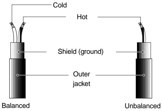
text_image
Cold Hot Shield (ground) Outer jacket Balanced UnbalancedBalanced
The advantage of a balanced cable is its ability to reject external interference.
Therefore, it is suitable for handling a small level signal or transferring over long distances. The LR16 provides the following balanced connectors.
| Inputs/outputs | Connectable connectors |
| [INPUT 1-16] | XLR-3-12 connector, 3-conductor TRS or 2-conductor phone plug |
| [STEREO OUT (L, R)] | XLR-3-11 connector |
| [GROUP OUT 1 - 4] | 2-conductor phone plug |
| [PHONES] | 3-conductor TRS phone plug |
Unbalanced
An unbalanced cable is mainly used for handling line level signals.
The LR16 provides the following balanced connectors.
| Inputs/outputs | Connectable connectors |
| [INSERT 1 - 8] | 3-conductor TRS phone plug |
| [EFF SEND] | 2-conductor phone plug |
| [AUX SEND 1 - 3] | 2-conductor phone plug |
| [ST MIX OUT (L, R)] | RCA pin plug |
| [MONITOR OUT (L, R)] | 2-conductor phone plug |
| [TAPE IN (L, R)] | RCA pin plug |
Connector types
| XLR-3-11 connector (balanced) | 2 1 3 1 2 3 |
| XLR-3-12 connector (balanced) | 1 Ground |
| 2 Hot | |
| 3 Cold | |
| RCA pin plug (unbalanced) | Tip Sleeve |
| Tip Hot | |
| Sleeve Ground | |
| 3-conductor TRS phone plug (balanced) | MON OUT/AUX SEND GROUP OUT/EFF SEND |
| Tip Hot | |
| Ring Cold | |
| Sleeve Ground | |
| INSERT | |
| Tip Output | |
| Ring Input | |
| Sleeve Ground | |
| PHONES/INPUT | |
| Tip L | |
| Ring R | |
| Sleeve Ground | |
| 2-conductor phone plug (unbalanced) | Tip Sleeve |
| Tip Hot | |
| Sleeve Ground |
Names and functions
text_image
GROUP (+48u) EFF SEND (-28u) ALIX SEND (-20u) INSERT INSERT INSERT INSERT INSERT R STEREO OUT (+48u) L ST MIX OUT (+10u) USB M3X OUT FOOT SW CONTROLLER PANEL LOCK FOSTEX WHIPING WARNING STRAW OUT OF 50% OR 50% ON BEANS OR DETAIL OR PATTERN PHANTOM POWER AC-IN Fostex LR16 LIVE RECORDING MIXERMain unit (Rear panel)
Main unit (Front panel)

natural_image
Simple diagram with a switch and a network icon inside a rectangular box (no text or labels)Control unit (Rear panel)
text_image
1 2 3 4 5 6 7 8 9 10 11 12 13 14 15 16 L/RIS LEK RECINCING METER FDSTEX RUM TRIM EQ EQ EQ EQ EQ EQ EQ EQ EQ EQ EQ EQ EQ EQ EQ EQ EQ EQ EQ EQ EQ EQ EQ EQ EQ EQ EQ EQ EQ EQ EQ EQ EQ EQ EQ EQ EQ EQ EQ EQ EQ EQ EQ EQ EQ EQ EQ EQ EQ EQ AQI 1000Ω 100Ω 100Ω 100Ω 100Ω 100Ω 100Ω 100Ω 100Ω 100Ω 100Ω 100Ω 100Ω 100Ω 100Ω 100Ω 100Ω 100Ω 100Ω 100Ω 100Ω 3.5V 3.5V 3.5V 3.5V 3.5V 3.5V 3.5V 3.5V 3.5V 3.5V 3.5V 3.5V 3.5V 3.5V 3.5V 3.5V 3.5V 3.5V 3.5V 3.5V 3.5S 12 V 12 V 12 V 12 V 12 V 12 V 12 V 12 V 12 V 12 V 12 V 12 V 12 V 12 V 12 V 12 V 12 V 12 V 12 V 12 V 12 V 12 V 12 V 12 V 12 V 12 V L RIS LEK RECINCING METER FDSTEX RUM EQ EQ EQ EQ EQ EQ EQ EQ EQ EQ EQ EQ EQ EQ EQ EQ EQ EQ EQ EQ EQ EQ EQ EQ EQ EQ EQ EQ EQ EQ EQ EQ EQ EQ EQ EQ EQ EQ EQ EQ EQ EQ EQ EQ EQ EQ EQ EQ EQ EQUITY/INJ/INJ/INJ/INJ/INJ/INJ/INJ/INJ/INJ/INJ/INJ/INJ/INJ/INJ/INJ/INJ/INJ/INJ/INJ/INJ/INJ/INJ/INJ/INJ/INJ/INJ/INJ/INJ/INJ/INJ/INJ/INJ/INJ/INJ/ L RIS LEK RECINCING METER FDSTEXControl unit (Top panel)
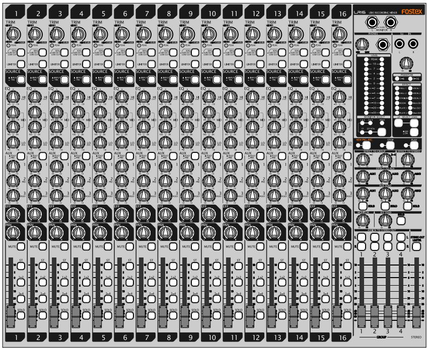
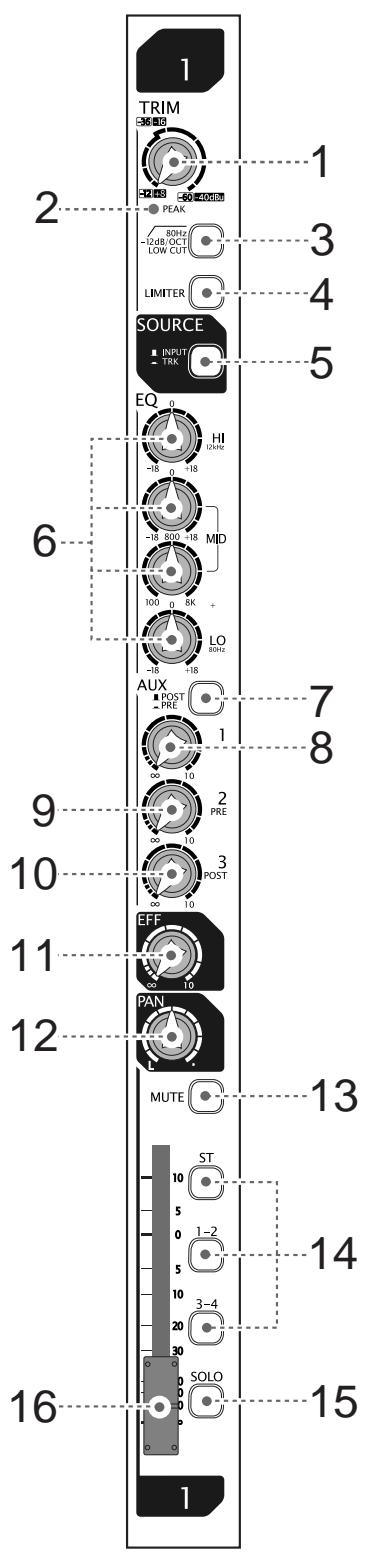
Control unit (input channel 1 through 16)
text_image
1 TRIM 2 3 4 5 SOURCE 6 EQ HI 1/2MHz -18 0 +18 -18 800 +18 100 0 8K + LO -18 +18 AUX POST PRE 1 2 PRE 3 POST 9 10 EFF 11 PAN 12 MUTE 13 ST 10 5 0 1-2 5 10 3-4 20 30 SOLO 16 1(1) [TRIM] control
Adjusts the gain of each input signal. Set this control appropriately so that the [PEAK] indicator lights at the maximum input level. By adjusting this control appropriately, the LR16 can accept a signal within -60dBu and -12dBu for mic input, while it can accept a signal within -40dBu and +8dBu for line input.
(2) [PEAK] indicator
Lights up when an input channel signal overloads. You should set the [TRIM] control appropriately so that this indicator does not light frequently.
(3) [LOW CUT] switch
Switches on (■) or off (■) of the low cut filter (high pass filter). When on, the frequency range below 80 Hz is cut at -12 dB/oct. This function is performed in the analog stage.
(4) [LIMITER] switch
Switches on (■) or off (■) of the limiter function. The limiter works to prevent signal clipping when the input level exceeds the certain level. The limiter function is performed in the analog stage.
(5) [SOURCE (INPUT/TRK)] switch
Selects the source signal for each input channel. When the switch is set to the up position (■), the signal fed to the [INPUT] connector is selected. When the switch is set to the down position (■), the recorder playback signal is selected. Pressing the switch toggles the source signal. When selecting the recorder playback signal (■), the [TRIM] control is not effective.
(6) [EQ HI/MID/LO] controls
These controls control gain for each EQ band (high, middle, and low), as well as the middle frequency.
When you set the gain control at the center position, no boost or cut is applied.
The following table shows the EQ type, center (or cut-off) frequency and boost/cut range of each EQ band.
| Band | EQ type | Center (or cut-off) frequency | Boost/cut range |
| HIGH | Shelving type | 12kHz | +/-18dB |
| MID | Peaking type | 100 Hz to 8 kHz (sweepable) | |
| LOW | Shelving type | 80Hz |
![FOSTEX LR16 - [EQ HI/MID/LO] controls - 1](/content/2025/01/168456/images/5fb89cacc530d439747f24dc06004530555cbefd1481964288a936882e6120aa.jpg)
text_image
1 TRIM 36 MHz -2 dB -50 dB -40 dB PEAK 60Hz -12dB/DCT LOW CUT LIMITER SOURCE INPUT TRK 5 EQ HI -18 0 +18 -18 800 18 MID 100 0 8K + LO -18 +18 AUX POST PRE 1 8 9 2 PRE 10 3 POST 11 EFF 10 PAN MUTE 13 ST 10 5 0 1-2 5 10 3-4 20 30 SOLO 16 1(7) [POST/PRE] switch
Selects post-fader or pre-fader feed of the AUX 1 buss (each press of the switch alternates the selection).
When the switch is set to the up (■) position, post-fader is selected. When the switch is set to the down (■) position, pre-fader is selected.
(8) [AUX 1] control
Adjusts the signal level fed to the AUX 1 buss from each input channel. The post-fader or pre-fader signal selected by the [POST/PRE] switch is fed to the AUX 1 buss.
(9) [AUX 2 (PRE)] control
Adjusts the signal level fed to the AUX 2 buss from each input channel. The pre-fader signal is fed to the AUX 2 buss.
(10) [AUX 3 (POST)] control
Adjusts the signal level fed to the AUX 3 buss from each input channel. The post-fader signal is fed to the AUX 3 buss.
(11) [EFF] send control
Adjusts the signal level fed to the EFF buss from each input channel. The post-fader signal is fed to the EFF buss, therefore, fader setting affects the signal sent to the [EFF] buss.
(12) [PAN] control
Determines the signal balance between the left and right of the stereo busses or odd and even busses of group buss pairs 1-2 and 3-4.
Rotating the control to the right (clockwise) increases the amount of the signal from the channel going to the right of the stereo buss, while decreases the amount of the signal going to the left of the stereo buss.
Rotating the control to the left (counterclockwise) increases the amount of the signal from the channel going to the left of the stereo buss, while decreases the amount of the signal going to the right of the stereo buss.
(13) [MUTE] switch
Switches the mute function on or off. When the switch is set to the down position (■), the post fader signal of the channel is muted.
(14) [ST/1-2/3-4] assign switches
Assign or deassign the input channel signal to the corresponding buss pairs (Stereo, groups 1-2 or groups 3-4). When the switch is set to the down position (—), the signal is assigned to the corresponding buss pair. You can assign the signal to more than one buss pair at the same time.
(15) [SOLO] switch
Switches the solo function on or off. When the switch is set to the down position (☐), the pre-fader signal can be monitored via the solo buss. When the [SOLO] switch on any input channel is set to ON, the [SOLO] indicator on the monitor section flashes.
(16) Channel fader
Adjusts the output level of the input channel.
Control unit (Master channel)
(17) [SUB IN] jacks and control
You can connect a CD player, MD player, etc to the jacks and adjust the input level using the control. By default, the input signals from the [SUB IN] jacks are assigned to input channel 15 and 16, however, you can change the assignment to any desired channel pairs using the "Input" menu of the MENU mode.
![FOSTEX LR16 - [SUB IN] jacks and control - 1](/content/2025/01/168456/images/a91386e4d09ece5847066857d96b8f749a3fe443c2f0c712adf4522e504c2b2f.jpg)
text_image
LR16 LIVE RECORDING MIXER FOSTEX L MONITOR R PHONES SUB IN MIN MAX L R LEVEL PEAK 17 10 19 7 10 4 20 2 0 -2 -4 -7 -10 -20 -30 MONITOR SELECT PHANTOM 20 1-2 3-4 SOLO 21 ST. EFF RTN SELECT 22 NEW PRJ REC STOP PLAY 23 EFFECT TO GROUP EFFECT TO STEREO 24 1-2 3-4 25 AUX1 AUX2 AUX3 26 AUX1 AUX2 AUX3 27 AUX1 AUX2 AUX3 28 SOLO SOLO SOLO 29 MONITOR EFF SEND SOLO 30 ASSIGN TO STEREO OUT OUTPUT L L R LIMITER 31 GROUP STEREO(18) Monitor section
![FOSTEX LR16 - [SUB IN] jacks and control - 2](/content/2025/01/168456/images/b0c65e0440e63dc7650a9b54f9f074db53094fcb723cad875bfbbacbe8585793.jpg)
text_image
L MONITOR (~10dBV) R a PHONES c b MIN MAX LEVELS PEAK 10 7 4 2 0 -2 -4 -7 -10 -20 -30 d MONITOR SELECT 1 2 3 4 5 6 7 8 9 10 11 12 13 14 15 16 17 18 19 20 21 22 23 24 25 26 27 28 29 30 31 32 33 34 35 36 37 38 39 40 41 42 43 44 45 46 47 48 49 50 51 52 53 54 55 56 57 58 59 60 ST EFF RTN e f(a) [MONITOR L/R] jacks
You can connect a monitor amplifier or powered monitor speakers to these jacks. The output level can be adjusted by the [MONITOR] control.
(b) [PHONES] jack
Connects headphones. You can adjust the output level using the [PHONES] and [MONITOR] controls.
(c) [PHONES] control
Adjusts the output level of the [PHONE] jack.
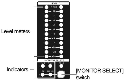
Indicate the output level of the monitor signal selected by the [MONITOR SELECT] switch (or the solo monitor signal).
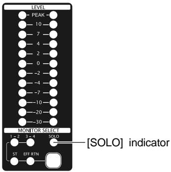
(e) [SOLO] indicator
When at least one of the [SOLO] switches is set to ON, the [SOLO] indicator slowly flashes, while the solo monitor signal is output from the [MONITOR (L/R)] and [PHONES] jacks.
(f) [MONITOR SELECT] switch
Selects signals to be monitored. You can select from Groups 1-2, Groups 3-4, Stereo and Effect return by pressing the switch as many time as required.
When solo monitor is active, the selection is not effective.
![FOSTEX LR16 - [MONITOR SELECT] switch - 1](/content/2025/01/168456/images/398f6fb52d17e06d7c82b491e4a0a0987f3cb5efc0dd786aea5ecd9d39755439.jpg)
text_image
LRIS LIVE RECORDING MIXER FOSTEX (<=10dBV) MONITOR R PHONES SUB IN MIN MAX L R LEVEL PEAK 10 7 4 2 0 -2 -4 -7 -10 -20 -30 MONITOR SELECT 1 - 2 3 - 4 SOLO ST. EFF RTN EFFECT HALL 1 VOCAL 1 HALL 2 VOCAL 2 STADIUM VOCAL 3 ROOM Mono DLY PLATE 1 Pan DLY PLATE 2 Short DLY SELECT OFF ON NEW PRI REC STOP PLAY 1-2 3-4 EFFECT TO GROUP EFFECT TO STEREO 10 10 AUX1 AUX2 AUX3 10 10 AUX SEND 10 10 SOLO SOLO SOLO MONITOR EFF SEND SOLO ASSIGN TO STEREO OUT OUTPUT L L R LIMITER 1 2 3 4 30 40 50 60 70 80 90 100 100 100 100 100 100 100 100 100 100 100 100 100 100 100 100 100 100 100 100 100 100 100 100 100 150 GROUP STEREO(19) [PHANTOM (1-8, 9-16)] indicators
Each indicator illuminates when the corresponding [PHANTOM] switch ([1-8] or [9-16]) is set to ON. The phantom power is supplied to the XLR connectors in eight input groups.
(20) Internal effects section
![FOSTEX LR16 - [PHANTOM (1-8, 9-16)] indicators - 1](/content/2025/01/168456/images/0443702dda998282e874df9509da468b8110183a5c191b0f16c40d399d9b7484.jpg)
text_image
EFFECT HALL 1 VOCAL 1 HALL 2 VOCAL 2 STARDIM VOCAL 3 ROOM Mono DLY PLATE 1 Pan DLY PLATE 2 Short DLY EFFECT a- b- c- OFF - ON(a) [EFFECT] indicator
The current effect type selected by the [SELECT] up/down switches illuminates.
(b) [SELECT] up/down switches
Select an effect type (the indicator for the selected effect type illuminates).
When the [EFFECT] on/off switch is set to ON (☐), the current effect is effective.
(c) [EFFECT] on/off switch
Switches the internal effects on (■) or off (■). When the switch is set to the down position (ON), the current effect selected by the [SELECT] up/down switches is effective.
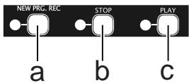
(21) Recorder control section
The keys in this section are used for controlling the recorder on the main unit.
text_image
NEW PRG. REC a b c STOP PLAY(a) [NEW PRJ. REC] key
Pressing the key while at least one of tracks is record-armed creates a new project onto the internal hard disk and starts recording. (Note: Do not use this key when you start recording in Insert mode.)
(b) [STOP] key
Locates to the beginning of the current project (ABS 0) and stops.
(c) [PLAY] key
Starts playback of the current project.
![FOSTEX LR16 - [PLAY] key - 1](/content/2025/01/168456/images/83172924138e3e2679e6b9b5965f083b5b64114cca6d85d903b06219cf962e8e.jpg)
text_image
LR16 LIVE RECORDING MIXER FOSTEX L MONITOR R PHONES SUB IN MIN MAX LEVEL PEAK 10 7 4 2 0 -2 -4 -7 -10 -20 -30 MONITOR SELECT 1 - 2 3 - 4 SOLO ST EFF RTN SUB IN L R PHANTOM 1-8 2- EFFECT HALL 1 VOCAL 1 HALL 2 VOCAL 2 STADIUM VOCAL 3 ROOM Mono DLY PLATE 1 Pan DLY PLATE 2 Short DLY SELECT OFF ON NEW PRJ REC STOP PLAY 21 22 EFFECT TO GROUP EFFECT TO STEREO 1-2 3-4 10 10 10 EFFECT TO AUX AUX1 AUX2 AUX3 10 10 10 AUX1 AUX2 AUX3 10 10 10 SOLO SOLO SOLO 23 24 25 26 MONITOR EFF SEND SOLO 10 10 10 ASSIGN TO STEREO OUT L OUTPUT R LIMITER 1 2 3 4 30 40 50 60 70 80 90 100 10 10 10 10 10 10 10 10 10 10 10 10 10 10 10 10 10 10 10 10 10 10 10 10 10 10 10 10 10 10 10 10 10 18 31 GROUP STEREO(22) [EFFECT TO GROUP] controls
Each control adjusts the output level from the internal effects to the corresponding group buss pairs (1-2 or 3-4).
(23) [EFFECT TO STEREO] control
Adjusts the output level from the internal effects to the stereo busses.
(24) [EFFECT TO AUX (1, 2, 3)] controls
Each control adjusts the output level from the internal effects to the corresponding AUX buss (1, 2 or 3).
(25) [AUX SEND] controls / [SOLO] switches
Each [AUX SEND] control adjusts the output level of the corresponding AUX SEND (1, 2 or 3) output. Each [SOLO] switch allows you to monitor the soloed signal of the corresponding AUX SEND (1, 2 or 3) output. When the switch is down, the solo function is engaged. Each press of the switch toggles between on and off.
(26) [MONITOR] control
Adjusts the output level of the [MONITOR (L/R)] and [PHONES] jacks.
The output level of the [PHONES] jack is controlled by the [PHONES] and [MONITOR] controls.
(27) [EFF SEND] control / [SOLO] switch
Adjusts the output level of the EFFECT SEND. Each [SOLO] switch allows you to monitor the soloed signal of the EFFECT SEND output. When the switch is down (—), the solo function is engaged. Each press of the switch toggles between on and off.
(28) [ASSIGN TO STEREO OUT] switches
Each switch allows you to send the post signal of the corresponding GROUP fader to the [STEREO OUT L/R] jacks. When the switch is down, the signal is sent.
(29) [OUTPUT LIMITER] switch
Activates or deactivates the limiter function for all the buss outputs (stereo L/R outputs, group outputs 1 through 4, Aux send outputs 1 through 3, effect send output, and monitor outputs). When the switch is down (■), the limiter function is active.
(30) [GROUP 1-4] faders
Each fader adjusts the output level of the corresponding group output signal which is output from the [GROUP OUT] jack.
(31) [STEREO] fader
Adjusts the output level of the stereo output signal which is output from the [STEREO OUT (L/R)] and [ST MIX OUT (L/R)] jacks.
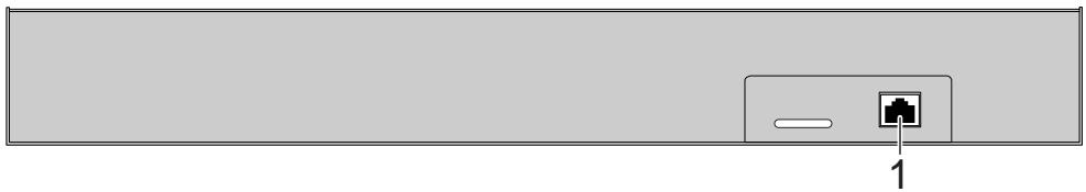
Control unit (rear panel)
natural_image
Simple diagram showing a device with an internal port and a labeled pin (no text or symbols beyond the number 1)(1) [TO CONTROLLER] connector
Used to connect to the [CONTROLLER] connector of the main unit using the supplied (or a different) CAT5 cable.
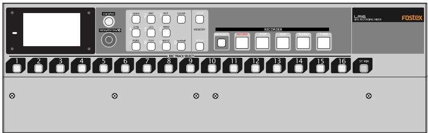
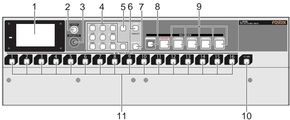
Main unit (front panel)
text_image
1 2 3 4 5 6 7 8 9 FOSTEX L16 LINE NECKRATING INDEX RECK TRACK SELECT ST MRS 11 10(1) Display
Displays the input/output level of audio signals or project information.
(2) [EXIT/NO] key
Used to exit the MENU mode or cancel the setting in the MENU mode.
(3) [MENU/ENTER] knob
This knob has two functions. Rotating this knob functions as the [MENU] dial, while pressing this knob functions as the [ENTER] key. In this manual, we describe it as the "[MENU] dial" or "[ENTER] key" depending on whether you use it by rotating it or pressing it.
[ENTER] key function:
Pressing it while the recorder is stopped enters the MENU mode. It is also used to confirm a setting or execute a function in the MENU mode.
[MENU] dial function:
In the MENU mode, rotating it selects an option or enters an alphanumeric character for a name.
While the Home screen is shown, you can adjust the display contrast by rotating it.
(4) Numeric keys
Pressing a numeric key performs instant start of a mixed file set to the memory play list. When you enter/edit a name (for example, when editing a project name via the "Rename" menu item in the "Project" menu of the MENU mode), you can enter a desired character by using an appropriate key.
(5) [CLEAR] key
When you edit a name (for example, when editing a project name via the "Rename" menu item in the "Project" menu of the MENU mode), you can delete a character. When you edit time data, you can reset the time value.
(6) [MEMORY STOP] key
Stops playback in memory play mode. This key does not work except in memory play mode.
(7) [MEMORY SETUP] key
Pressing this key enter the memory setup mode, in which you can make setting required for memory play.
(8) [NEW PROJECT] key
Toggles the new project mode on and off. When the new project mode is set to on, the key illuminates. In this mode, if you press the [PLAY] key while holding down the [RECORD] key, the LR16 automatically creates a new project onto the hard disk drive and starts recording.
(9) Transport keys
[RECORD] key
If you press the key alone, the recorder enters record ready mode. The key starts flashing while the track meter for a record-armed track on the display shows the input level of the track.
If you press the [PLAY] key while holding down the [RECORD] key, the LR16 performs as follows depending on whether the LR16 is in new project mode or not.
- When the LR16 is in new project mode:
The LR16 creates a new project and starts recording.
- When the LR16 is not in new project mode:
The LR16 starts recording to the current project in insert mode.
In this condition, you can make additional recording to the project or editing such as punch in/out.
[STOP] key
Stops the transport except when memory play is being performed.
If you press the [REWIND] or [F FWD] key while holding down the [STOP] key, the LR16 performs as follows.
• [STOP] key + [REWIND] key
The LR16 locates to the beginning of the project (ABS 0).
• [STOP] key + [F FWD] key
The LR16 locates to the recording end position (REC END).
[PLAY] key
Starts playback of the current project.
[REWIND] key
When the transport is stopped, pressing this key fast-rewinds the transport. During play-back, pressing this key rewinds the transport at 5x speed with audible cue.
If you press this key while holding down the [STOP] key, the LR16 locates to the beginning of the project (ABS 0).
[F FWD] key
When the transport is stopped, pressing this key fast-forwards the transport. During play-back, pressing this key forwards the transport at 4x speed with audible cue.
If you press this key while holding down the [STOP] key, the LR16 locates to the recording end position (REC END).
(10) [ST MIX] key
You can record a stereo mix signal to the stereo mix track. This key arms or disarms the stereo mix track. When armed, the key flashes.
After recording starts, the key lights up. You can record to the stereo mix track and multitracks (1 through 16) simultaneously.
(11) [REC TRACK SELECT (1-16)] keys
Each of these keys arms or disarms the corresponding track. When armed, the key flashes. After recording starts, the key lights up.
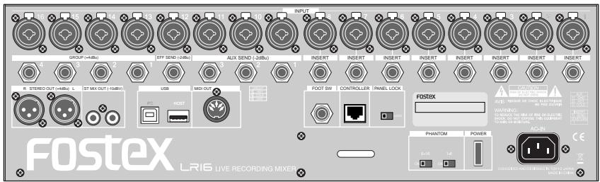
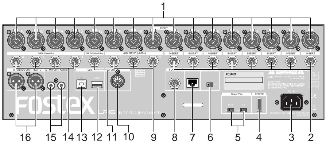
Main unit (rear panel)
text_image
GROUP (+48Bu) EFF SEND (-26Bu) AUX SEND (-26Bu) INPUT INSERT INSERT INSERT INSERT INSERT INSERT INSERT INSERT M STEREO OUT (+48Bu) L EST MIX OUT (-108V) USB HOST FOSTEX AVIS: PROBE DE CHOC IN FROCK IN PAE OUT OF WARNING: TURBONE THE RISK OF FIRE OR ELECTRIC SNOCK DO NOT EXPOSE THIS EQUIPMENT TO PAIN OR WARNING PHANTOM POWER CONSENSIANTICUM FOR INFOV APPR MADE IN CIR 16 15 14 13 12 11 10 9 8 7 6 5 4 3 2 Fostex LIF6 LIVE RECORDING MIXER(1) [INPUT (1 through 16)] connectors
Each connector accepts a mic or line level analog audio signal. The connector is a combo type - a combined XLR connector and phone jack in one. You can connect a microphone to the XLR connector or connect a line signal to the phone jack. (Note that you cannot use the XLR receptacle and phone jack on a same combo connector simultaneously.)
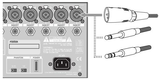
(2) [INSERT (1 through 8)] jacks
Each jack is used for connecting an external effects processor such as a compressor/limiter. To connect an external effects processor, use a Y-cable as shown below.
![FOSTEX LR16 - [INSERT (1 through 8)] jacks - 1](/content/2025/01/168456/images/0600dc814e91d0d3606449d2981c5d7b1c9cb89b731914aec55cb0bde5140d24.jpg)
natural_image
Pure electrical circuit lines without any symbols(3) [AC IN] connector
Used to connect the supplied power cord.
(4) [POWER] switch
Turns on or off the LR16.
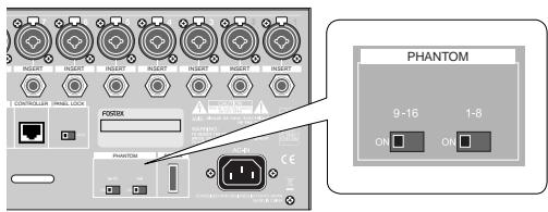
(5) [PHANTOM (1-8, 9-16)] switches
You can supply phantom power to the XLR INPUT connectors in eight channel groups (1-8 and 9-16) using these switches.
When the [PHANTOM] switch is set to ON, the corresponding [PHANTOM] indicator on the control panel is illuminated.
(6) [PANEL LOCK (ON/OFF)] switch
You can disable the recorder operation from the panel by setting this switch to "LOCK". In this condition, the lock icon is shown on the display. You can switch the panel lock setting even during recording.
(7) [CONTROLLER] connector
Used to connect to the [TO CONTROLLER] connector on the rear panel of the control unit using the supplied (or a different) CAT-5 cable.
(8) [FOOT SW] jack
Used to connect to a footswitch for performing punch in/out or memory play start. You can set the footswitch function via the "Foot SW" menu item in the "System" menu of the MENU mode.
(9) [AUX SEND (1, 2, 3)] jacks
Each of these unbalanced phone jacks outputs the corresponding AUX SEND buss signal at -2dBu nominal level. You can connect to a stage monitor, effects processor, etc.
(10) [MIDI OUT] port
Used to connect to the MIDI IN port of an external MIDI device. From this port, MTC (MIDI Time Code) is output. The MTC frame rate can be set using the "Default frame" menu item in the "System" menu of the MENU mode.
(11) [EFF SEND] jack
This unbalanced phone jack outputs the EFFECT buss signal at -2dBu nominal level. You can connect to the input jack of an effects processor, etc.
(12) [USB HOST] port
By connecting a FAT16 or FAT32 USB memory stick to this port, you can copy project data (or stereo mix file) to the memory stick and then transfer it to a computer. You can also use the USB memory stick when upgrading the version. (Note that you cannot use the [USB HOST] and [USB PC] ports simultaneously.)
(13) [USB PC] port
By connecting to the [USB] port of a personal computer using a USB cable, you can transfer files between the computer and the LR16 by the computer operation. (Note that you cannot use the [USB HOST] and [USB PC] ports simultaneously.)
(14) [GROUP OUT (1, 2, 3, 4)] connectors
These balanced phone jacks output the group buss signals at +4dBu nominal level. You can connect these jacks to input connectors of an external mixer, etc.
(15) [ST MIX OUT (L, R)] jacks
These unbalanced RCA pin jacks output the stereo L and R buss signals. You can connect these jacks to an external master recorder, etc.
(16) [STEREO OUT (L, R)] connectors
These XLR balanced connectors output the stereo L and R buss signals. You can connect these connectors to a power amplifier for driving main speakers on stage, etc.
Display details
HOME screen
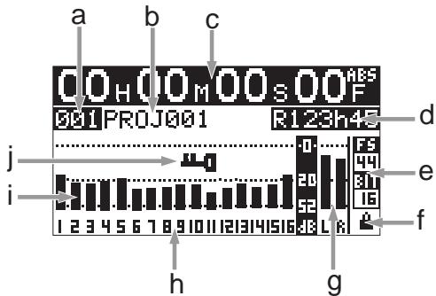
While stopped or during playback or recording, the Home screen as below is shown. On the Home screen, the following items are displayed.
text_image
a b c 00H 00M 00S 00F 001PROJ001 R123h45 d j i e f 1 2 3 4 5 6 7 8 9 10 11 12 13 14 15 16 17 18 19 20 21 22 23 24 25 26 27 28 29 30 31 32 33 34 35 36 37 38 39 40 h ga) Project number
The project number of the current project is displayed in three digits.
The project number of the first project created on the internal hard disk is "001" and the project number is counted up each time a project is created.
b) Project name
The project name of the current project is displayed.
The project name of the first project created on the internal hard disk is "PROJ001" and the last three-digit number is counted up each time a project is created.
You can specify the default project name via the "Rename" menu item in the "Project" menu of the MENU mode.
c) Time display
The current ABS time of the current project is displayed in "hour:minite:second:frame" format. If no recording has been made to the internal hard disk, the time display shows "--H--M--S--F". During recording or playback, the current recorder status icon is shown in the frame digit, as below.
| Recorder | Icon |
| During playback | [C72T] |
| During recording |  |
| During forwarding |  |
| During rewinding | [T46S] |
d) Remain
The remaining time of the hard disk is displayed. It is displayed only while arming tracks or during recording. Increasing the number of recording tracks decreases the remaining time.
e) Sampling frequency and bit rate
The combination of sampling frequency and bit rate currently selected in the "Default FS" menu item in the "System" menu of the MENU mode is displayed. When recording a new project, this combination is applied. If the displayed combination does not match the current project, it flashes.
f) Protection
The lock icon is displayed when the current project is protected. You cannot make recording or editing when a protected project is loaded. You can protect or deprotect the current project using the "Protect" menu item in the "Project" menu of the MENU mode.
g) Level meters for stereo busses
The signal levels of the stereo L and R busses are displayed.
h) Tracks
A record-armed track is displayed in flashing. When you starts recording, it changes from flashing to lighting.
If you arm track 4: "4" flashes.

If you arm stereo mix track using the [ST MIX] key: "LR" flashes.

i) Level meters for tracks 1 through 16
Each level meter shows the input (recording) level when the corresponding track is in record ready or record mode, while it shows the track playback level when the corresponding track is being played back.
j) Panel lock
When the panel lock function is engaged, the panel lock key icon is displayed. When the lock key is displayed, the operation keys on the recorder section of the main unit are disabled.
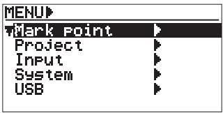
MENU mode screen
While the recorder stopped, pressing the [ENTER] key in the recorder section of the main unit enters the MENU mode and brings up the following screen.
text_image
MENU Mark point Project Input System USBThis screen allows you to select a main menu. By using the [MENU] dial to highlight the desired main menu and pressing the [ENTER] key, the display shows the next menu level. (The ">" icon on the screen indicates that the next menu level exists.)
There are the following five main menus.
- Mark point menu
- Project menu
- Input menu
- System menu
- USB menu
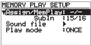
Memory play setup mode screen
While the recorder stopped, pressing the [MEMORY SETUP] key in the recorder section of the main unit brings up the memory play setup screen as below.
text_image
MEMORY PLAY SETUP Assign/MemPlay: -/- SubIn :15/16 Sound file ▶ Play mode :ONCEIn this screen, you can make setting for memory play including the channel assignment, playlist setting and play mode setting, as well as destination assignment of the "Sub In" signal.
Mixer functions
Mixer basics
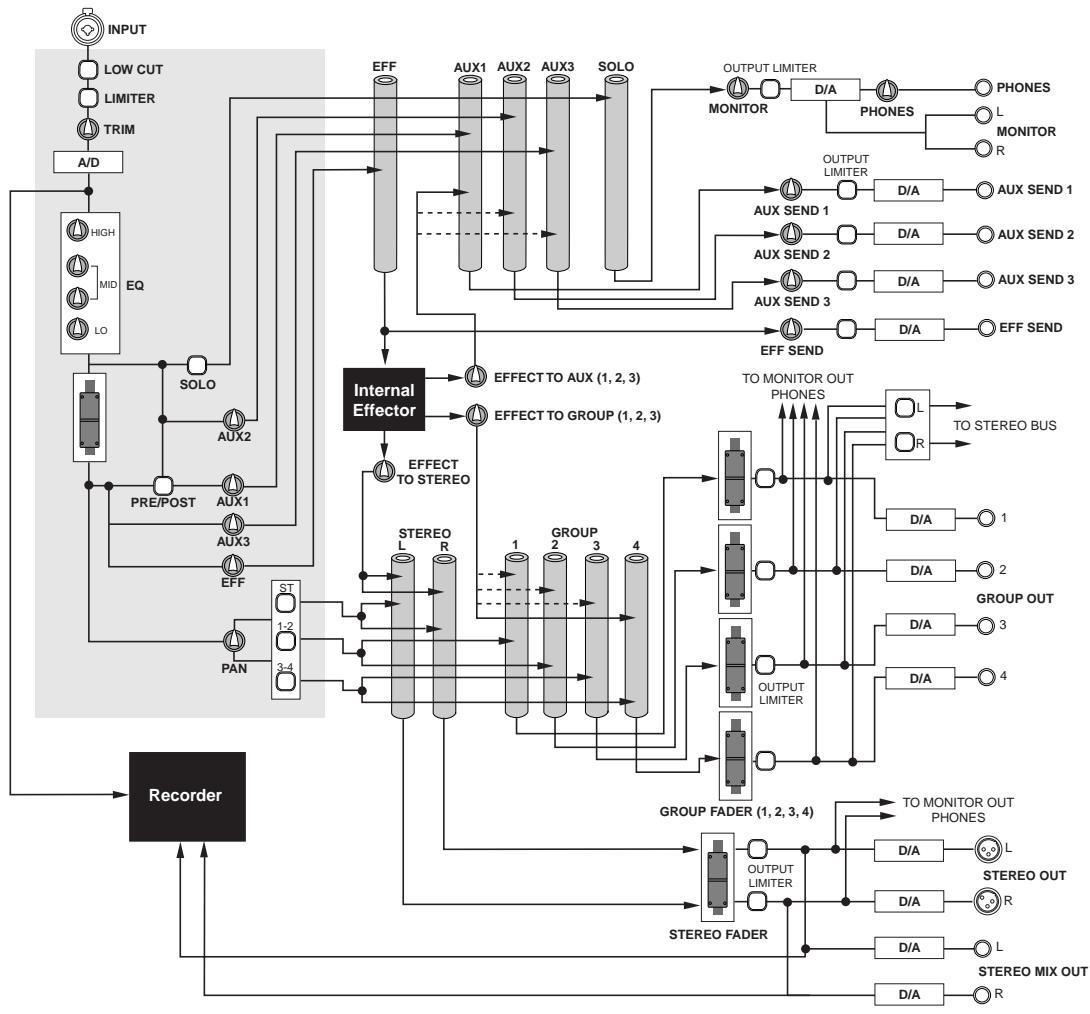
Signal flow of the mixer
A mixer accepts audio signals and modifies them, then mixes them.
The following diagram shows how the input signals flow through the mixer section of the LR16. As the diagram indicates, an analog signal from the [INPUT] connector is level-adjusted by the [TRIM] control and converted to digital, then sent to the channel fader via the EQ. After the channel fader, the pan control adjusts the left and right (or odd and even) balance of signal sent to stereo left and right busses (or odd and even group busses). Then the stereo signal is finally level-adjusted by the [STEREO] fader and output from the [STEREO OUT (L, R)] connectors.
A buss sums signals and mixes them. In the diagram below, busses are shown as pipes.
The LR16 provides the following eleven busses: stereo busses (L, R), group busses (1, 2, 3, 4), AUX busses (1, 2, 3), effect buss and solo buss. Each buss sums signals. The mixed signal may be D/A converted and fed to an external device, or directly fed to the internal effects.
The LR16 is equipped with a hard disk drive for recording and playback. You can perform up to 16 track multitrack recording as well as stereo mix recording. (You can perform multitrack and stereo recording simultaneously.)
flowchart
graph TD
    INPUT["INPUT"] --> LOWCUT["LOW CUT"]
    LOWCUT --> LIMITER["LIMITER"]
    LIMITER --> TRIM["TRIM"]
    TRIM --> A/D["A/D"]
    A/D --> EQ["HIGH"]
    EQ --> LO["LO"]
    EQ --> SOLO["SOLO"]
    SOLO --> AUX2["AUX2"]
    AUX2 --> PRE/POST["PRE/POST"]
    PRE/POST --> AUX1["AUX1"]
    AUX1 --> AUX3["AUX3"]
    AUX3 --> EFF["EFF"]
    EFF --> PAN["PAN"]
    PAN --> ST["ST"]
    ST --> REC["Recorder"]
    REC --> A/D
    EQ --> SOLO
    SOLO --> SOLO
    SOLO --> InternalEffector["Internal Effector"]
    InternalEffector --> EFFECTTOStereo[" EFFECT TO STEREO "]
    EFFECTTOStereo --> STEREO_L["STEREO L"]
    EFFECTTOStereo --> STEREO_R["STEREO R"]
    STEREO_L --> GROUP1["GROUP 1"]
    STEREO_R --> GROUP2["GROUP 2"]
    GROUP1 --> OUTPUTLIMTER["OUTPUT LIMTER "]
    GROUP2 --> OUTPUTLIMTER["OUTPUT LIMTER "]
    OUTPUTLIMTER --> GROUPFADER["GROUP FADER (1, 2, 3, 4)"]
    GROUPFADER --> OUTPUTLIMITER["OUTPUT LIMITER"]
    OUTPUTLIMITER --> STEREOOUT["STEREO OUT"]
    OUTPUTLIMITER --> STEREOOUTOUT["STEREO MIX OUT"]

    InternalEffector --> EFFECTTOUX[" EFFECT TO AUX (1, 2, 3)"]
    EFFECTTOUX --> OUTPUTLIMITER["OUTPUT LIMITER"]

    OUTPUTLIMITER --> MONITOR["MONITOR"]
    MONITOR --> D/A["D/A"]

    D/A --> PHONES["PHONES"]
    D/A --> MONITOR["R MONITOR"]

    D/A --> DIA["AUX SEND 1"]
    D/A --> AUXSEND1["AUX SEND 1"]

    DIA --> DIA1["D/A"]
    DIA --> AUXSEND2["AUX SEND 2"]

    DIA --> DIA2["D/A"]
    DIA --> AUXSEND3["AUX SEND 3"]

    DIA --> DIA3["D/A"]
    DIA --> DIA1
    DIA2 --> DIA2
    DIA3 --> DIA3

    DIA1 --> DIA10["D/A"]
    DIA2 --> DIA10
    DIA3 --> DIA10

    DIA2 --> DIA20["D/A"]
    DIA3 --> DIA20

    DIA3 --> DIA30["D/A"]
    DIA4 --> DIA40["D/A"]
    DIA5 --> DIA40

    DIA40 --> DIA40OUT["TO MONITOR OUT PHONES"]
    DIA40OUT --> TOSTEREOBUS["TO STEREO BUS"]

    DIA40OUT --> DIA41["D/A"]
    DIA40OUT --> DIA42["D/A"]

    DIA41 --> DIA41OUT["TO MONITOR OUT PHONES"]
    DIA41OUT --> DIA43D4["GROUP OUT"]

    DIA42 --> DIA420["D/A"]
    DIA43D4 --> DIA44D4["OUTPUT LIMTER"]

    DIA43D4 --> DIA45D4["GROUP FADER (1, 2, 3, 4)"]

    DIA50["D/A"] --> DIA50OUT["TO MONITOR OUT PHONES"]
    DIA50OUT --> DIA51D4["STEREO OUT"]

    DIA50OUT --> DIA51D4["STEREO MIX OUT"]

    style REC fill:#99CCFF,stroke:#333
Connecting sources
- Connecting sources to the input connectors
Each of mixer channels 1 through 16 provides a combo type -- a combined XLR connector and phone jack in one. You can connect a microphone to the XLR connector or connect a line signal to the phone jack. (The phone jack can accept both balanced and unbalanced signals.)
You can adjust the input gain using the [TRIM] control on each mixer channel strip.
text_image
5 INSERT INSERT INSERT INSERT INSERT FOSTEX PHANTOM POWER ACAN 2014-06-23 19:00 AM AIA BARRIANCE R.Q. 100 MHz WATERBING ON/OFFIC/CHINA POWER ACAN 2014-06-23 19:00 AM AIA BARRIANCE R.Q. 100 MHz WATERBING ON/OFFIC/CHINA POWER ACAN- Phantom power supply setting
48 V phantom power can be supplied to the XLR input connectors. For most of condenser microphones, the phantom power is required.
You can turn on or off phantom power using the [PHANTOM] switches in eight channel groups (1-8 and 9-16) using these switches.
text_image
PHANTOM 9-16 1-8 ON ON
Usually phantom power does not damage a dynamic microphone, however, do not connect an old ribbon microphone to an input connector to which phantom power is supplied.
- Selecting channel source
Setting the [SOURCE] switch on each mixer channel to "INPUT" (■) selects the channel input signal. Setting the [SOURCE] switch to "TRK" (—) selects the track playback signal, or the [SUB IN] signal or the memory play signal when it is assigned to the channel.
Adjusting the input level
The [TRIM] control adjust the head amp gain of each input signal. To get the optimum gain, set this control appropriately so that the [PEAK] indicator lights at the maximum input level.
By adjusting this control appropriately, the LR16 can accept a signal within -60dBu and -12dBu for an XLR connector is connected, while it can accept a signal within -40dBu and +8dBu when a phone plug is connected.
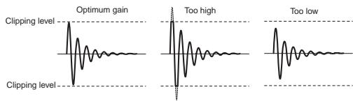
text_image
Optimum gain Too high Too low Clipping level Clipping levelTo adjust the gain while monitoring an input signal, connect headphones to the [PHONES] jack (or connect a powered monitor speaker to the [MONITOR OUT] jacks) and rotate the [PHONES] control (or [MONITOR] control) little to the right from the leftmost position. In this condition, perform the following.
1) Press the [SOLO] switch on the mixer channel to solo the channel.
2) Input the source sound (from a microphone or line).
3) Rotate the [PHONES] control (or [MONITOR] control) clockwise gradually.
4) Adjust the [TRIM] control to get the optimum gain.
5) After adjusting the gain, press the [SOLO] switch to de-solo the channel.
- Low-cut filter
The low-cut filter is often known as a high-pass filter. It passes high frequencies and eliminates low frequencies.
By pressing the [LOW CUT] switch to set to "ON" (—), the ultra low frequencies under 80 Hz are eliminated with a -12 dB/octave slope.
The low-cut filter helps prevent wind noise, mic handling noise, etc. It is recommended to enable the low-cut filter when you connect a microphone.
- Limiter
The limiter can be used to prevent clipping when a too hot signal is input.
The limiter is does not work as far as an input signal is below the threshold level. When the input signal exceeds the threshold level, it reduces or attenuates the input signal thereby holding the output signal level too high.
The output limiter provided in the master section is effective to prevent damaging the main speakers in live or PA applications.
Equalizer
You can tailor the sound using the channel equalizer. For best results, the equalizer should be used to make the sound natural.
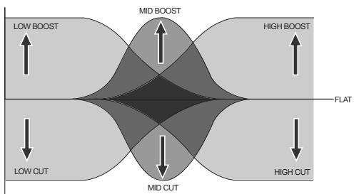
flowchart
graph TD
    A["LOW BOOST"] --> B["MID BOOST"]
    C["FLAT"] --> D["MID CUT"]
    E["LOW CUT"] --> F["MID CUT"]
    G["High BOOST"] --> H["FLAT"]
    I["High CUT"] --> J["FLAT"]
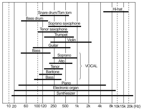
bar
| Instrument | Frequency (Hz) | | :--- | :--- | | Snare drum/Tom tom | 4000 | | Bass drum | 60 | | Soprano saxophone | 1000 | | Tenor saxophone | 1000 | | Trumpet | 500 | | Violin | 2000 | | Guitar | 500 | | Bass | 100 | | Soprano | 100 | | Alto | 100 | | Tenor | 500 | | Baritone | 500 | | Bassi | 100 | | Piano | 8000 | | Electronic organ | 10000 | | Synthesizer | 10000 | Hi-hat | 20000 |If the mixed sound is not clear, we recommend to find the channel which makes the mixed sound unclear and slightly cut the frequency range of the channel. To much boosting may make the mixed sound unclear.
Listen to the mixed sound repeatedly, comparing with the original (non-EQ) sound, and challenge to make your favorite sound.
Using of low-cut filter may be effective when you use a microphone.
EQ HIGH
The EQ HIGH is a shelving type EQ which provides up to 18 dB of boost or cut above 12 kHz. The center detent position of the control is the flat position. You can emphasize a cymbal or sharpen a vocal, keyboard or guitar by boosting the EQ HIGH. You can soften the high frequency sound by cutting the EQ HIGH.
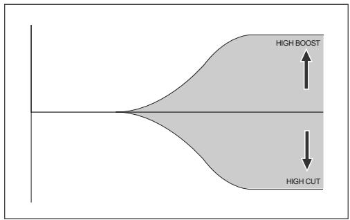
text_image
HIGH BOOST HIGH CUTEQ MID
The EQ MID is a peaking type EQ which provides up to 18 dB of boost and cut at the center frequency. You can sweep the center frequency between 100 Hz and 8 kHz. The center detent position of the control is the flat position. For most of sound sources, the mid frequency range absolutely effects the sound. Therefore, you can dramatically tailor the sound using the EQ MID.
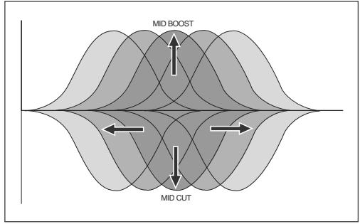
text_image
MID BOOST MID CUTEQ LO
The EQ LO is a shelving type EQ which provides up to 18 dB of boost or cut below 80 Hz. The center detent position of the control is the flat position. You can emphasize a kick, guitar, bass, etc.
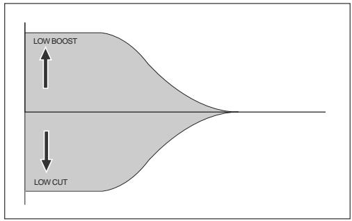
text_image
LOW BOOST LOW CUTUsing an external effect processor
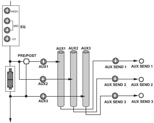
• Using AUX 1, 2 and 3
You can use AUX busses for sending channel signals to an external effects processor or stage monitor, etc.
The [AUX] send control on each mixer channel adjusts the amount of the channel signal sent to the AUX buss. The signal after the [AUX SEND] control in the master section which adjusts the total AUX buss level is output from the [AUX SEND] jack.
flowchart
graph TD
    A["High"] --> B["EQ"]
    C["MID"] --> B
    D["LO"] --> B
    B --> E["AUX1"]
    B --> F["AUX2"]
    B --> G["AUX3"]
    E --> H["AUX1"]
    F --> I["AUX2"]
    G --> J["AUX3"]
    H --> K["AUX SEND 1"]
    I --> L["AUX SEND 2"]
    J --> M["AUX SEND 3"]
There are two send signal types - pre-fader and post-fader. You can select pre- or post-fader for the AUX 1 buss. The AUX 2 buss is fixed to pre-fader, while the AUX 3 buss is fixed to post-fader.
In general, you send a post-fader signal to an effects processor, while you send a pre-fader signal for stage monitoring.
Pre-fader
A channel signal before the channel fader is sent to the buss. You can make a mix which is completely independent from the main mix. Pre-fader AUX sends are generally used for the monitor mix, because the channel faders don't affect the AUX send signals.
Any adjustments made to the front-of-the-house mix don't affect the balance heard by the performers onstage.
Post-fader
A channel signal after the channel fader is sent to the buss. Post-fader Aux sends are generally used for connecting to external effects processors. The send signal is raised or lowered according to the channel fader.
- Using Insert
The [INSERT] jack, as well as the AUX post send, is used for connecting to an external processor. Unlike the AUX send, you can apply effects to a single channel signal.
The LR16 provides the [INSERT] jacks for mixer channels 1 through 8. Each jack is used mainly for connecting a compressor, limiter, equalizer, etc.
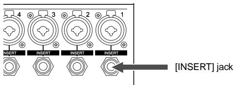
text_image
4 3 2 1 INSERT INSERT INSERT INSERT [INSERT] jackBy connecting an external effect processor to the [INSERT] jack, you can send the channel signal to the processor and receive the processed signal.
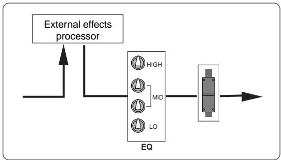
flowchart
graph LR
    A["External effects processor"] --> B["EQ"]
    B --> C["High"]
    B --> D["LO"]
    B --> E["MID"]
    B --> F["Output"]
The [INSERT] jack on the LR16 is the TRS-type unbalanced phone jack. You can make bidirectional connection with the effect processor using a "Y" cable as shown below.
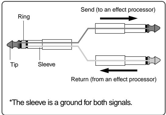
text_image
Ring Tip Sleeve Send (to an effect processor) Return (from an effect processor) *The sleeve is a ground for both signals.Using the internal effects processor
The LR16 features the internal effects (reverb/delay) processor, which allows applying effects to the mixer channel signals.
The effect send signal of each channel is adjusted by the [EFF] control after the channel fader. The effected (wet) signal is adjusted using the controls in the [EFFECT TO STEREO], [EFFECT TO GROUP] and [EFFECT TO AUX] sections and sent to the stereo, group and AUX busses.
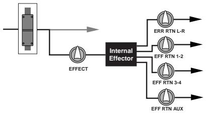
flowchart
graph LR
    A["Input"] --> B["Internal Effector"]
    B --> C["ERR RTN L-R"]
    B --> D["EFF RTN 1-2"]
    B --> E["EFF RTN 3-4"]
    B --> F["EFF RTN AUX"]
    B --> G["EFFECT"]
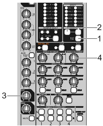
- Applying the internal effects
The following shows how to send the effected (wet) signal from the internal effects processor to the stereo L/R buss.
text_image
EQ 1 2 3 4 5 6 7 8 9 10 11 12 13 14 15 16 17 18 19 20 21 22 23 24 25 26 27 28 29 30 31 32 33 34 35 36 37 38 39 40 41 42 43 44 45 46 47 48 49 50 51 52 53 54 55 56 57 58 59 60 61 62 63 64 65 66 67 68 69 70 71 72 73 74 75 76 77 78 79 80 81 82 83 84 85 86 87 88 89 90 91 92 93 94 95 96 97 98 99 100(1) Set the [EFFECT ON/OFF] switch to "ON" (=).
(2) Select the desired effect type using the [SELECT UP/DOWN] switch.
The indicator for the selected type is illuminated. (See the next page for details about each effect type.)
(3) Adjust the effect send level of the channel signal using the [EFF] control on each mixer channel.
Note that the effect send level is affected by the channel fader.
(4) Adjust the effected (wet) signal level sent to the stereo L/R buss using the control in the [EFFECT TO STEREO] section
Adjust the effected signal level while monitoring the stereo buss signal using headphones or monitor speakers.
- About the effect types
| HALL 1 | Standard hall reverb; detailed and transparent, with a moderate amount of early reflections. |
| HALL | Stadium reverb characterized by long early reflections. |
| STADIUM | Reverb simulating an auditorium with suppressed reverberation. |
| ROOM | Room reverb simulating a moderate space with some sparkle. |
| PLATE 1 | Modem-sounding plate reverb with wide bandwidth. |
| PLATE 2 | Plate reverb with a gentle character. |
| VOCAL1 | All-purpose hall reverb with no early reflections, and uniform decay at all frequencies. |
| VOCAL 2 | Plate-like reverb is added to a spacious short delay. This blends well with any genre of music. |
| VOCAL 3 | All-purpose reverb (karaoke style) that makes any vocal sound professional. |
| Mono DLY | Mono delay. |
| Pan DLY | Panning delay. |
| Short DLY | Short delay. |
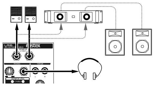
Monitoring
You can monitor the signal using headphones via the [PHONES] jack or using monitor speakers via the [MONITOR L/R] jacks.
flowchart
graph TD
    A["Audio Device"] --> B["Speaker"]
    C["Audio Device"] --> D["Speaker"]
    E["Audio Device"] --> F["Speaker"]
    G["Audio Device"] --> H["Speaker"]
    I["Audio Device"] --> J["Speaker"]
    K["Audio Device"] --> L["Speaker"]
    M["Audio Device"] --> N["Speaker"]
    O["Audio Device"] --> P["Speaker"]
    Q["Audio Device"] --> R["Speaker"]
    S["Audio Device"] --> T["Speaker"]
    U["Audio Device"] --> V["Speaker"]
    W["Audio Device"] --> X["Speaker"]
    Y["Audio Device"] --> Z["Speaker"]
    AA["Audio Device"] --> AB["Speaker"]
    AC["Audio Device"] --> AD["Speaker"]
    AE["Audio Device"] --> AF["Speaker"]
    AG["Audio Device"] --> AH["Speaker"]
    AI["Audio Device"] --> AJ["Speaker"]
    AK["Audio Device"] --> AL["Speaker"]
    AM["Audio Device"] --> AN["Speaker"]
    AO["Audio Device"] --> AP["Speaker"]
    AQ["Audio Device"] --> AR["Speaker"]
    AS["Audio Device"] --> AT["Speaker"]
    AU["Audio Device"] --> AV["Speaker"]
    AW["Audio Device"] --> AX["Speaker"]
    AY["Audio Device"] --> AZ["Speaker"]
    BA["Audio Device"] --> BB["Speaker"]
    BC["Audio Device"] --> BD["Speaker"]
    BE["Audio Device"] --> BF["Speaker"]
    BG["Audio Device"] --> BH["Speaker"]
    BI["Audio Device"] --> BJ["Speaker"]
    BK["Audio Device"] --> BL["Speaker"]
    BM["Audio Device"] --> BN["Speaker"]
    BO["Audio Device"] --> BP["Speaker"]
    BP --> BQ["Audio Headset"]
The signal to be monitored can be selected using the [MONITOR SELECT] switch. Each press of the switch changes the monitor signals and the indicator for the current monitor signal (ST, 1-2, 3-4 or EFF RTN) is lit.
text_image
LEVEL PEAK 10 7 4 2 0 -2 -4 -7 -10 -20 -30 Level meters MONITOR SELECT INDICATORS ST EEF. KTN SOLID [MONITOR SELECT] switch| ST | You can monitor the stereo L and R buss signal, which is output from the [STEREO OUT (L, R)] jacks. |
| 1-2 | You can monitor the group 1 and 2 buss signals, which are output from the [GROUP (1, 2)] jacks. |
| 3-4 | You can monitor the group 3 and 4 buss signals, which are output from the [GROUP (3, 4)] jacks. |
| EFFRTN | You can monitor the output signal (wet signal) of the internal effects processor. |
The output level of the [PHONES] jack is controlled by the [MONITOR] and [PHONES] controls, while the output level of the [MONITOR L/R] jacks is controlled by the [MONITOR] control. The output levels of the monitoring signals are shown on the level meters above the [MONITOR SELECT] switch.
- Solo monitor
By setting the [SOLO] switch(es) to ON ( ), you can solo monitor the corresponding channel signal(s).
If at least one of the [SOLO] switches is set to ON, the [SOLO] indicator slowly flashes.
text_image
LEVEL PEAK 10 7 4 2 0 -2 -4 -7 -10 -20 -30 MONITOR SELECT 1-2 3-4 SOLO ST EFF RTN [SOLO] indicatorYou can find the [SOLO] switches on channels 1 through 16, the effect send, and AUX sends 1 through 3 (see below).
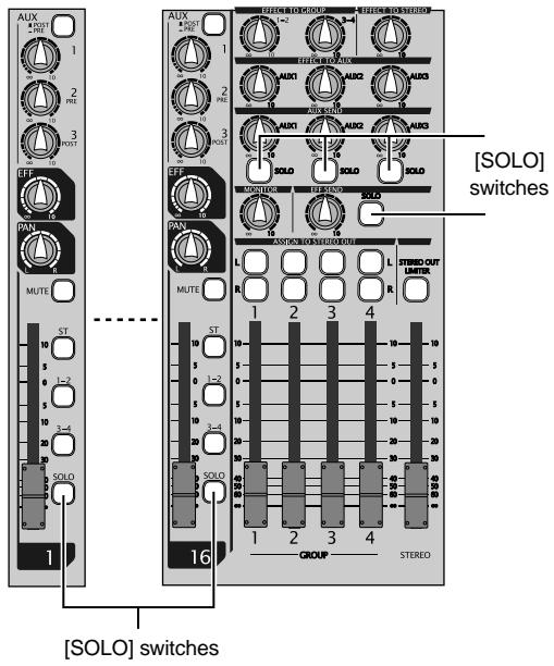
text_image
[SOLO] switches GROUP STEREO 16 1 MUTE ST 10 5 0 2 5 10 3-4 20 20 16 1 2 3 4 L R L R 1 2 3 4 [SOLO] switchesChannel grouping
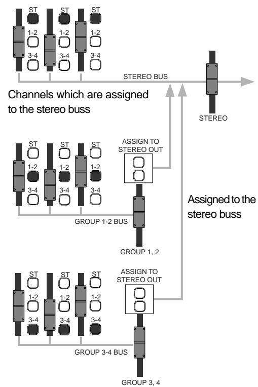
You can group channels to group busses for effective mixing.
Using the channel grouping function, you can adjust levels of grouped channels using a single fader while maintaining the balance between channels.
By setting the group assign switch (1-2 or 3-4) of a channel to ON, the channel signal is sent to group busses 1 and 2 or 3 and 4. A group buss signal is output from the [GROUP OUT] jacks.
When the [ASSIGN TO STEREO OUT] switch above the group fader is set to ON, the group buss signal is output to the corresponding stereo buss.
For example, it would be a good idea to assign channels for drums to a group. You can control the level of drums using the corresponding group fader without altering the balance.
flowchart
graph TD
    A["ST"] --> B["1-2"]
    A --> C["1-2"]
    A --> D["1-2"]
    A --> E["3-4"]
    F["ST"] --> G["1-2"]
    F --> H["1-2"]
    F --> I["1-2"]
    F --> J["3-4"]
    K["ST"] --> L["1-2"]
    K --> M["1-2"]
    K --> N["1-2"]
    K --> O["3-4"]
    P["ST"] --> Q["1-2"]
    P --> R["1-2"]
    P --> S["1-2"]
    P --> T["3-4"]
    U["ST"] --> V["1-2"]
    U --> W["1-2"]
    U --> X["1-2"]
    U --> Y["3-4"]
    Z["ST"] --> AA["1-2"]
    Z --> AB["1-2"]
    Z --> AC["1-2"]
    Z --> AD["3-4"]
    AE["ST"] --> AF["1-2"]
    AE --> AG["1-2"]
    AE --> AH["1-2"]
    AE --> AI["3-4"]
    AJ["ST"] --> AK["1-2"]
    AJ --> AL["1-2"]
    AJ --> AM["1-2"]
    AJ --> AN["3-4"]
    AO["ST"] --> AP["1-2"]
    AO --> AQ["1-2"]
    AO --> AR["1-2"]
    AO --> AS["3-4"]
    AT["ST"] --> AU["1-2"]
    AT --> AV["1-2"]
    AT --> AW["1-2"]
    AT --> AX["3-4"]
    AY["ST"] --> AZ["1-2"]
    BA["ST"] --> BB["1-2"]
    BB --> BC["1-2"]
    BB --> BD["3-4"]
    BE["ST"] --> BF["1-2"]
    BG["ST"] --> BH["1-2"]
    BH --> BI["1-2"]
    BH --> BJ["3-4"]
    BK["ST"] --> BL["1-2"]
    BM["ST"] --> BN["1-2"]
    BN --> BO["1-2"]
    BN --> BP["3-4"]
    BQ["ST"] --> BR["1-2"]
    BS["ST"] --> BT["1-2"]
    BT --> BU["1-2"]
    BU --> BV["3-4"]
    BW["ST"] --> BX["1-2"]
    BY["ST"] --> BZ["1-2"]
    BZ --> CA["1-2"]
    CA --> CB["3-4"]
    CC["ST"] --> CD["1-2"]
    CE["ST"] --> CF["1-2"]
    CF --> CG["1-2"]
    CG --> DH["3-4"]
    DI["ST"] --> DJ["1-2"]
    DK["ST"] --> DL["1-2"]
    DL --> DM["1-2"]
    DM --> DN["3-4"]
    DO["ST"] --> DOB["1-2"]
    DB["ST"] --> DC["1-2"]
    DC --> DD["1-2"]
    DD --> DP["3-4"]
    EQ["ST"] --> EQB["1-2"]
    EQB --> EQC["1-2"]
    EQC --> EQD["3-4"]
    EQD --> EQE["3-4"]
Channels which are assigned to the group busses
Using SUB IN
You can connect a stereo audio source such as a CD player, MD player, etc., to the [SUB IN (L, R)] jacks and output it directly from the control unit.
Therefore, you can connect a BGM source and play it back during a break in the show, etc.
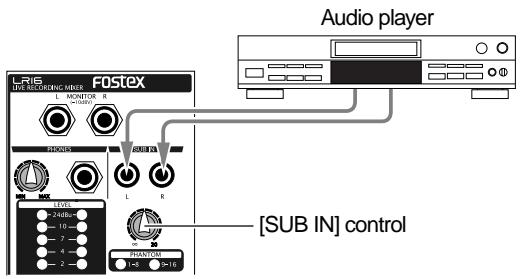
text_image
Audio player L16 LIVE RECORDING MIXER FOSTEX R200M L R [SUB IN] control PHANTOM +145 +16The input signals from the [SUB IN] jacks are level-adjusted by the [SUB IN] control. The signals from the [SUB IN] jacks are assigned to channels 15 and 16 by default, however, you can change the assignment using the "Input" menu of the MENU mode (see "Other functions" on page 79 for details).
The following shows the setting example for playing back the signals from the [SUB IN] jacks by the main speakers of a live stage.
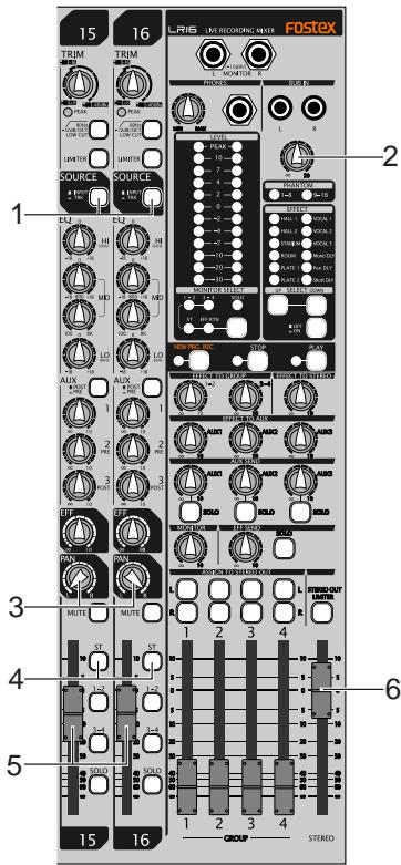
text_image
15 16 LRIS - LIME RECOATING MIXER FOSTEX TRIM TRIM 1 2 3 4 5 6 7 8 9 10 11 12 13 14 15 16 SOURCE SOURCE 1 2 3 4 5 6 7 8 9 10 11 12 13 14 15 16 MUTE MUTE MUTE MUTE MUTE MUTE MUTE MUTE MUTE MUTE MUTE MUTE MUTE MUTE MUTE MUTE MUTE MUTE MUTE MUTE MUTE MUTE MUTE MUTE MUTE MUTE MUTE MUTE MUTE MUTE MUTE MUTE MUTE MUTE MUTE MUTE MUTE MUTE MUTE MUTE MUTE MUSE MUSE MUSE MUSE MUSE MUSE MUSE MUSE MUSE MUSE MUSE MUSE MUSE MUSE MUSE MUSE MUSE MUSE MUSE MUSE MUSE MUSE MUSE MUSE MUSE MUSE MUSE MUSE MUSE MUSE MUSE MUSE MUSE MUSE MUSE MUSE MUSE MUSE MUSE MUSE MUSE MUSOLO SOLD SOLD SOLD SOLD SOLD SOLD SOLD SOLD SOLD SOLD SOLD SOLD SOLD SOLD SOLD SOLD SOLD SOLD SOLD SOLD SOLD SOLD SOLD SOLD SOLD SOLD SOLD SOLD SOLD SOLD SOLD SOLD SOLD SOLD SOLD SOLD SOLD SOLD SOLD SOLD SOLD SOLD SOLD SOLD SOLD SOLD SOLD SOLD SOLD SOLD S(1) Set the [SOURCE] switches on channels 15 and 16 to "TRK" (—).
The input signals from the [SUB IN] jacks are selected as the sources of channels 15 and 16.
(2) Use the [SUB IN] control to adjust the level of the signals from the [SUB IN] jacks.
You can use the [SUB IN] control to adjust the level of the signals from the [SUB IN] jacks, but cannot use the [TRIM] control for them.
The level of the signals after the [SUB IN] control are displayed on the level meters of the display.
(3) To output the signals from the [SUB IN] jacks in stereo, set the [PAN] control on channel 15 to "L" and set the [PAN] control on channel 16 to "R".
(4) Set the [ST] assign switches on channels 15 and 16 to "ON" (—).
The signal from the [SUB IN] jacks is routed to the stereo L/R buss.
(5) Use the channel faders on channel 15 and 16 to control the output level of the channel signals sent to the stereo L/R buss.
(6) Use the [STEREO] faders on channels 15 and 16 to control the level of the stereo buss signal output from the [STEREO OUT (L, R)] connectors, which affects the main speaker volume.
Block diagram
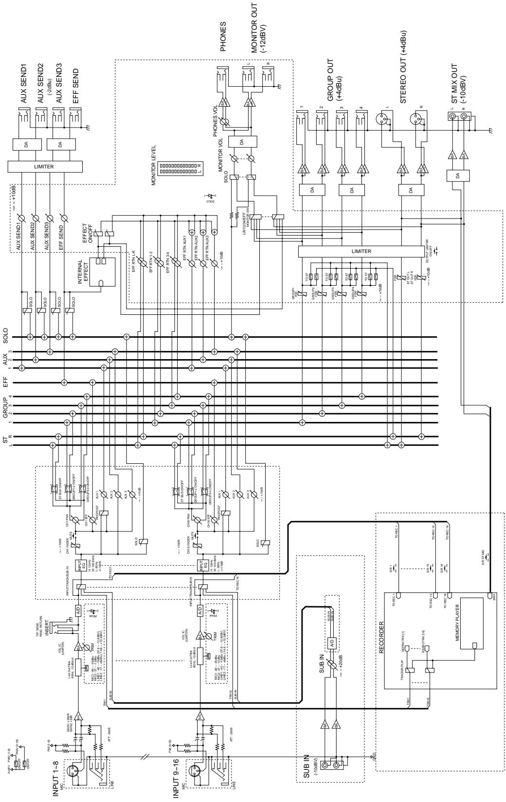
flowchart
graph TD
    subgraph INPUT 1-8
        A["MC"] --> B["OUT"]
        B --> C["ATT-266B"]
        C --> D["SUB IN"]
        D --> E["TRIN0L"]
        E --> F["SUB IN"]
        F --> G["SUB IN"]
    end

    subgraph INPUT 9-16
        H["MC"] --> I["OUT"]
        I --> J["ATT-266B"]
        J --> K["SUB IN"]
        K --> L["TRIN0L"]
        L --> M["SUB IN"]
    end

    subgraph SUB IN
        N["PER"] --> O["+20dB"]
        P["RECORDER"] --> Q["TRIOM/PLAY"]
        R["MEMORY PLAYER"] --> S["TO REC1"]
        T["TO REC1"] --> U["TO REC1.1"]
        V["TO REC1"] --> W["TO REC1.5"]
        X["TO REC1"] --> Y["TO REC1.6"]
    end

    subgraph INPUT 1-8
        Z["INPUT 1-8"] --> AA["OUT"]
        AA --> AB["ATT-266B"]
        AB --> AC["SUB IN"]
        AC --> AD["TRIN0L"]
        AD --> AE["SUB IN"]
        AE --> AF["SUB IN"]

    subgraph INPUT 9-16
        AG["INPUT 9-16"] --> AH["OUT"]
        AH --> AI["ATT-266B"]
        AI --> AJ["SUB IN"]
        AJ --> AK["TRIN0L"]

    subgraph SUB IN
        AL["SUB IN (-10dBV)"]
        AM["SUB IN A/D"]
        AN["SUB IN A/D"]
    end

    subgraph INPUT 1-8
        AO["INPUT 1-8"] --> AP["OUT"]
        AP --> AQ["ATT-266B"]
        AQ --> AR["SUB IN"]
        AR --> AS["TRIN0L"]

    end

    subgraph INPUT 9-16
        AT["INPUT 9-16"] --> AU["OUT"]
        AU --> AV["ATT-266B"]

    subgraph SUB IN
        AW["SUB IN (-10dBV)"]

    end

    subgraph INPUT 1-8
        AX["INPUT 1-8"] --> AY["OUT"]
        AY --> AZ["ATT-266B"]

    subgraph INPUT 9-16
        BA["INPUT 9-16"] --> BB["OUT"]
        BB --> BC["ATT-266B"]

    subgraph SUB IN
        BD["SUB IN (-10dBV)"]

    end

    subgraph INPUT 1-8
        BE["INPUT 1-8"] --> BF["OUT"]
        BF --> BG["ATT-266B"]

    subgraph INPUT 9-16
        BH["INPUT 9-16"] --> BI["OUT"]
        BI --> BJ["ATT-266B"]

    subgraph SUB IN
        BK["SUB IN (-10dBV)"]

    end

    subgraph INPUT 1-8
        BL["INPUT 1-8"] --> BM["OUT"]
        BM --> BN["ATTT-266B"]

    subgraph INPUT 9-16
        BO["INPUT 9-16"] --> BP["OUT"]
        BP --> BQ["ATTT-266B"]

    subgraph SUB IN
        BR["SUB IN (-10dBV)"]

    end

    subgraph INPUT 1-8
        BS["INPUT 1-8"] --> BT["OUT"]
        BT --> BU["ATTT-266B"]

    subgraph INPUT 9-16
        BV["INPUT 9-16"] --> BW["OUT"]
        BW --> BX["ATTT-266B"]

    subgraph SUB IN
        BY["SUB IN (-10dBV)"]

    end

    subgraph INPUT 1-8
        BZ["INPUT 1-8"] --> CA["OUT"]
        CA --> CB["ATTT-266B"]

    subgraph INPUT 9-16
        CC["INPUT 9-16"] --> CD["OUT"]
        CD --> CE["ATTT-266B"]

    subgraph SUB IN
        CF["SUB IN (-10dBV)"]

    end

    subgraph INPUT 1-8
        GD["INPUT 1-8"] --> DH["OUT"]
        DH --> DI["ATTT-266B"]

    subgraph INPUT 9-16
        DJ["INPUT 9-16"] --> DE["OUT"]
        DE --> DF["ATTT-266B"]

    subgraph SUB IN
        DG["SUB IN (-10dBV)"]

    end

    subgraph INPUT 1-8
        DHA["INPUT 1-8"] --> DH
        DH --> DI
        DI --> DF
    end

    subgraph INPUT 9-16
        DHX["INPUT 9-16"] --> DHX
        DHX --> DIX
        DIX --> DFX
    end

    subgraph SUB IN
        DHY["SUB IN (-10dBV)"]

    end

    subgraph INPUT 1-8
        DHXH["INPUT 1-8"] --> DHXH
        DHXH --> DHXH
        DHXH --> DHXH
    end

    subgraph INPUT 9-16
        DHXH --> DHXH
        DHXH --> DHXH
    end

    subgraph SUB IN
        DHYH["SUB IN (-10dBV)"]

    end

    subgraph INPUT 1-8
        DHYH --> DHYH
        DHYH --> DHYH
        DHYH --> DHYH
    end

    subgraph INPUT 9-16
        DHYH --> DHYH
        DHYH --> DHYH
    end

    subgraph SUB IN
        DHYH --> DHYH
        DHYH --> DHYH
    end

    subgraph INPUT 1-8
        DHYH --> DHYH
        DHYH --> DHYH
        DHYH --> DHYH
    end

    subgraph INPUT 9-16
        DHYH --> DHYH
        DHYH --> DHYH
    end

    subgraph SUB IN
        DHYH --> DHYH
        DHYH --> DHYH
    end
Recorder functions
Recording/playback
Recorder basics
Before starting recording, understand the basics of the recorder of the LR16.
Recording format
The recorder section of the main unit is equipped with the 3.5 inch hard disk drive. You can record a linear 16 or 24 bit audio file at 44.1kHz or 48 kHz Fs.
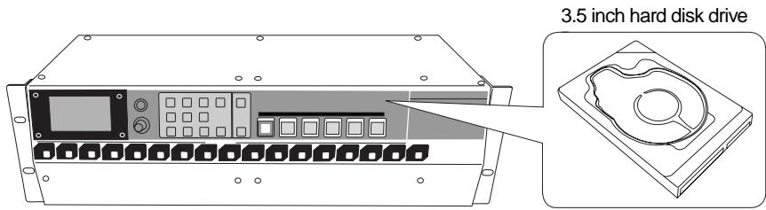
text_image
3.5 inch hard disk drive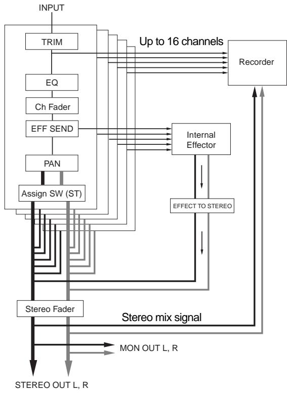
flowchart
graph TD
    INPUT --> TRIM
    TRIM --> EQ
    EQ --> Ch Fader
    Ch Fader --> EFF_SEND
    EFF_SEND --> PAN
    PAN --> Assign_SW["Assign SW (ST)"]
    Assign_SW --> StereoFader
    StereoFader --> STEREO_OUT["L, R"]
    STEREO_OUT["L, R"] --> MON_OUT["L, R"]
    MON_OUT["L, R"] --> Stereo_mixing["Stereo mix signal"]
    Stereo mixing --> EFFECT_TO_STEREO
    EFFECT_TO_STEREO --> Internal_Effector
    Internal_Effector --> Recorder
    Recorder --> UpTo16["Up to 16 channels"]
    EQ --> UpTo16
    EFF_SEND --> UpTo16
    PAN --> UpTo16
    Stereo mixing --> Counter
    Counter --> Record
The recorder section of the LR16 provides 16 multitracks and stereo L and R tracks. It allows direct recording of up to 16 channel analog signals and stereo mix recording simultaneously. Each analog input signal is converted to digital after being level-adjusted using the [TRIM] control and directly sent to the corresponding track, while it can be sent to the stereo tracks through the mixer channel where you can tailor the signal using the mixer functions including the equalizer, internal effects processor, etc.
Therefore, you can simultaneously perform multitrack recording and rough mix recording during live performance.
The recorder also provides basic multitrack recorder functions such as overdubbing and punch-in/out.
Recording mode
The LR16 recorder provides two recording modes: the new project mode and insert mode.
| New project mode | The LR16 automatically creates a new project and starts recording from the beginning of the project. To perform recording in new project mode, press the [PLAY] key while holding down the [RECORD] key when the [NEW PROJECT] key is set to "ON", or press the [NEW PRJ.REC] key regardless of [NEW PROJECT] key setting. |
| Insert mode | The LR16 starts recording from the beginning of an existing project or performs additional recording on an existing project which has been recorded. You can perform overdubbing, punch in/out, etc. To perform recording in insert mode, press the [PLAY] key while holding down the [RECORD] key when the [NEW PROJECT] key is set to "OFF". |
Project
When you performs recording in new project mode (or when you create a new project using the "Project" menu of the MENU mode), three folders as shown on the right are created in the root of the hard disk.
The folder at the top ("PROJ001") is called "project". You can make up to 250 projects on the hard disk.
Each project on the hard disk is independent and you can perform recording, playback, punch in/out, etc. without affecting the other projects. The LR16 automatically gives a project name to each project. The name of the first created project is "PROJ001" and the number (given by the last three digits) is automatically counted up each time a new project is created.
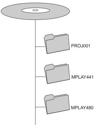
flowchart
graph TD
    A[" "] --> B["PROJ001"]
    A --> C["MPLAY441"]
    A --> D["MPLAY480"]
You can change a project name automatically given to a desired one later. (See page 66 for details.)
When you start recording for the first time, 16 mono WAV files for tracks 1 through 16, as well as the "2mix" and "LOG" folders, are automatically created in the "PROJ001" folder.
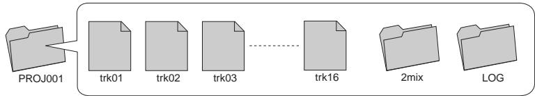
flowchart
graph LR
    A["PROJ001"] --> B["trk01"]
    B --> C["trk02"]
    C --> D["trk03"]
    D -.-> E["trk16"]
    E --> F["2mix"]
    F --> G["LOG"]
In the "2mix" folder, stereo mix files (stereo WAV files) created by stereo mix recording of the LR16 are stored. In the "LOG" folder, the ADL files of the project is stored.
You can play back mono files for tracks 1 through 16.
A stereo mix file can be played back using the memory play function. The ADL files stored in the "LOG" folder are used when you retrieve the pre-edited condition of an edited project, instead of the undo/redo function often found on other digital recorders. (See page 67 for details.)
Live recording
The following shows the setting example of live recording in which the LR16 is used as a PA mixer.
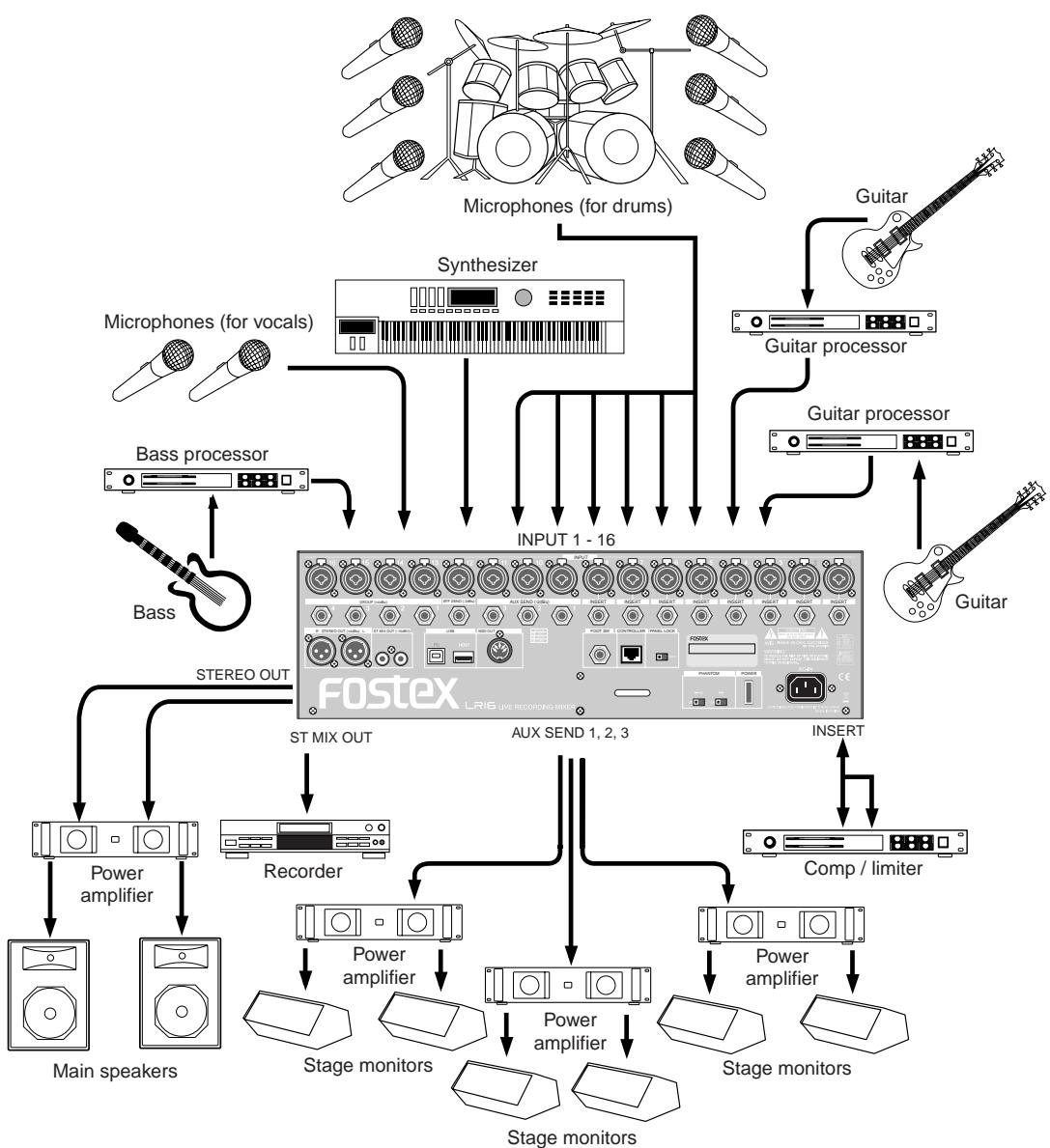
flowchart
graph TD
    A["Microphones (for drums)"] --> B["Synthesizer"]
    C["Microphones (for vocals)"] --> B
    D["Bass processor"] --> E["INPUT 1 - 16"]
    F["Bass"] --> E
    G["Guitar"] --> H["Guitar processor"]
    I["Guitar"] --> H
    J["Guitar"] --> H
    K["ST MIX OUT"] --> L["FOSTEX LRIS LIVE RECORDING MIX"]
    M["STREEO OUT"] --> L
    N["RECORDER"] --> O["AUX SEND 1, 2, 3"]
    P["Power amplifier"] --> Q["Main speakers"]
    R["Recorder"] --> S["Stage monitors"]
    T["Power amplifier"] --> U["Stage monitors"]
    V["Power amplifier"] --> W["Stage monitors"]
    X["Power amplifier"] --> Y["Stage monitors"]
    Z["COMP / limiter"] --> AA["Stage monitors"]
    AB["INSERT"] --> AC["Stage monitors"]
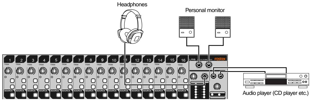
text_image
Headphones Personal monitor 1 2 3 4 5 6 7 8 9 10 1 12 13 14 15 16 TRIM TRIM TRIM TRIM TRIM TRIM TRIM TRIM TRIM TRIM TRIM TRIM TRIM TRIM TRIM TRIM TRIM TRIM TRIM TRIM TRIM TRIM TRIM TRIM TRIM TRIM TRIM TRIM TRIM TRIM TRIM TRIM TRIM TRIM TRIM TRIM TRIM TRIM TRIM TRIM TRIM TRIM TRIM TRIM TRIM TRIM TRIM TRIM TRIM TRIM TRIM SOURCE SOURCE SOURCE SOURCE SOURCE SOURCE SOURCE SOURCE SOURCE SOURCE SOURCE SOURCE SOURCE SOURCE SOURCE SOURCE SOURCE SOURCE SOURCE SOURCE SOURCE SOURCE SOURCE SOURCE SOURCE SOURCE SOURCE SOURCE SOURCE SOURCE SOURCE SOURCE SOURCE SOURCE SOURCE SOURCE SOURCE SOURCE SOURCE SOURCE SOURCE SOURCE SOURCE SOURCE SOURCE SOURCE SOURCE SOURCE SOURCE SOURCE SOURCE SOURCE SOURCE SOURCE SOURCE SOURCE SOURCE SOURCE SOURCE SOURCE SOURCE SOURCE SOURCE SOURCE SOURCE SOURCE SOURCE SOURCE SOURCE SOURCE SOURCE SOURCE SOURCE SOURCE SOURCE SOURCE SOURCE SOURCE SOURCE SOURCE SOURCE SOURCE SOURCE SOURCE SOURCE SOURCE SOURCE SOURCE SOURCE SOURCE SOURCE SOURCE SOURCE SOURCE SOURCE SOURCE SOURCE SOURCE SOURCE SOURCE SOURCE | FOSTEX Audio player (CD player etc.)You can perform live recording while you use the LR16 as a PA mixer on live stage.
Each channel input signal is directly routed to the corresponding recorder track (shown by the heavy line in the diagram on the right).
Each input signal is level-adjusted by the [TRIM] control and converted to digital, then routed to the recorder track, without being tailored by the equalizer, etc. Therefore, you can record pure input signals which are not affected by mixer setting for PA.
You can edit and mix down the signals recorded on tracks 1 through 16 after live performance.
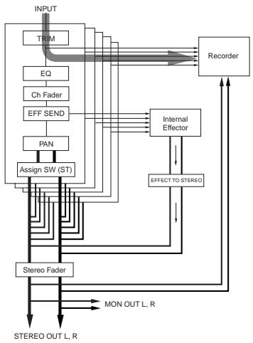
flowchart
graph TD
    INPUT --> TRIM
    TRIM --> EQ
    EQ --> Ch Fader
    Ch Fader --> EFF_SEND
    EFF_SEND --> PAN
    PAN --> Assign_SW(ST)
    Assign_SW(ST) --> Stereo Fader
    Stereo Fader --> MON_OUT_L.R
    MON_OUT_L.R --> RECER
    RECER --> Recorder
    RECER --> Internal_Effector
    Internal_Effector --> EFFECT_TO_STEREO
    EFFECT_TO_STEREO --> RECER
    RECER --> EQ
    EQ --> CH_FADER
    CH_FADER --> EFF_SEND
    EFF_SEND --> PAN
    PAN --> Assign_SW(ST)
    Assign_SW(ST) --> Stereo_Fader
    Stereo_Fader --> MON_OUT_L.R
    MON_OUT_L.R --> RECER
Mixed channel input signals are routed to the stereo mix track through the mixer channel (shown by the heavy line in the diagram on the right).
Each input signal goes to the mixer channel and is tailored using the EQ, internal effects, etc., then is routed to the stereo buss where all input signals are mixed, and then routed to the stereo mix track.
Therefore, the same signal as the [STEREO OUT] and [MON OUT] signal is recorded to the stereo mix track.
In other words, you can record the same signal as the PA output signal.
You can play back a stereo mix file recorded to the stereo mix track using the memory play function.
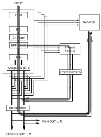
flowchart
graph TD
    INPUT --> TRIM
    TRIM --> EG
    EG --> Ch Fader
    Ch Fader --> EFF_SEND
    EFF_SEND --> PAN
    PAN --> Assign_SW(ST)
    Assign_SW(ST) --> Stereo Fader
    Stereo Fader --> MON_OUT_L_R
    MON_OUT_L_R --> STEREO_OUT_L_R
    STEREO_OUT_L_R --> Stereo Fader
    RECORDER --> Internal_Effector
    Internal_Effector --> EFF_SEND
    EFF_SEND --> EQ
    EQ --> TRIM
    EFF_SEND --> Assign_SW(ST)
    Assign_SW(ST) --> Stereo_Fader
    Stereo_Fader --> MON_OUT_L_R
    MON_OUT_L_R --> STEREO_OUT_L_R
    STEREO_OUT_L_R --> Stereo_Fader
You can record each input signal individually to the corresponding track (shown by the dotted line on the right diagram), while recording the stereo-mixed signal to the stereo mix track simultaneously.
In other words, you can record the same signal as the PA output signal, as well as record individual signals independently. You can edit and mix down the individual signals recorded on tracks 1 through 16 after live performance.
* You can play back the project recorded on tracks 1 through 16, while you can play back the stereo mix using the memory play function.
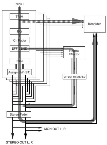
flowchart
graph TD
    INPUT --> TRIM
    TRIM --> EQ
    EQ --> Ch Fader
    Ch Fader --> EFF_SEND
    EFF_SEND --> PAN
    PAN --> Assign_SW(ST)
    Assign_SW(ST) --> Stereo_Fader
    Stereo_Fader --> MON_OUT_L.R
    MON_OUT_L.R --> STEREO_OUT_L.R
    STEREO_OUT_L.R --> StereoOUT_L.R
    RECORDER --> Internal_Effector
    Internal_Effector --> EFFECT_TO_STEREO
    EFFECT_TO_STEREO --> StereoOUT_L.R
    StereoOUT_L.R --> STEREO_OUT_L.R
The following shows the procedure for rehearsing recording to tracks 1 through 16 as well as to the stereo mix track simultaneously in new project mode during live performance. In the following description, it is assumed that no project is created to the internal hard disk ("No project" is shown on the display).
Preparation
(1) Select Fs/bit of the project and MTC frame rate.
By default, Fs/bit is set to "44.1kHz/16 bit" while MTC frame rate is set to "25fps". You can change them before recording.
(2) Change the destination channels of Sub In from “15/16” (default) to “-/-” (no channels are assigned).
You can now record to all of tracks 1 through 16.
Adjusting input level (=recording level) of each mixer channel
(1) Set the [SOURCE] switch on each of mixer channels 1 through 16 to "INPUT" (■).
The input source from the corresponding [INPUT] connector is selected as the channel source of each channel.
(2) Set all the [REC TRACK SELECT] keys (1 through 16) and the [ST MIX] key in the recorder section to ON.
All the keys start flashing. On the display, track numbers "1" through "16" and "LR" start flashing, while the recordable remaining time is shown.
![FOSTEX LR16 - Set all the [REC TRACK SELECT] keys (1 through 16) and the [ST MIX] key in the recorder section to ON. - 1](/content/2025/01/168456/images/1b122ed5cbf726f8e5a9d90ed8fdac288c2d92c05f92268c092047dda01e34c0.jpg)
text_image
H M S F(3) Press the [RECORD] key.
The key lights up and the level meters 1 through 16 on the display now show the recorder input levels (= mixer channel levels). text_image
RECORDER REFRICE RECORD STOP PLAY REIND FFMD Flashing(4) Use the [TRIM] control each of mixer channels 1 through 16 to adjust the input level.
Adjust the [TRIM] control appropriately so that the [PEAK] indicator is lit at the loudest part of playing. text_image
H M S Ftext_image
MONITOR SELECT 1 - 2 3 - 4 SOLO ST EFF RTN ST 1-2 3-4 SOLO ON (—)Adjusting the channel output levels sent to the stereo buss
After adjusting the input level of each channel, you can tailor the channel signal and send it to the stereo buss via the pan pot and channel fader. (This determines the sound output from the main speaker in live performance.) Before executing the following procedure, make sure that the "ST" indicator is lit and the [SOLO] indicator is unlit in the [MONITOR SELECT] section. text_image
MONITOR SELECT 1 - 2 3 - 4 SOLO ST EFF RTN Littext_image
ST ON (—) 10 5 0 1-2 5 10 20 30 SOLO 1 ~ 16 10 5 0 5 10 20 30 40 50 60 8 STEREOtext_image
H M S F ---Recording
text_image
RECORDER NEW PROJECT RECORD STOP PLAY REWCNT T FWD Lit Flashingbar
| Category | Value | |---|---| | 00 | 0 | | H | 0 | | 00M | 0 | | 08S | 0 | | F | 0 | | R005h48 | 0 | | FS | 0 | | 44 | 0 | | 81 | 0 | | 16 | 0 | | 20 | 0 | | 52 | 0 | | 56 | 0 | | L6 | 0 | | L8 | 0 | The values are estimated based on the provided code format.(3) To stop recording, press the [STOP] key in the recorder or mixer section.
If you press the [STOP] key in the recorder section, the recorder stops at the recording end position (REC END). If you press the [STOP] key in the mixer section, the recorder skips back to the beginning of the project (ABS 0) and stops.flowchart
graph TD
    A["PROJ001"] --> B["take001trk01"]
    A --> C["take001trk02"]
    A --> D["take001trk03"]
    A --> E["take001trk04"]
    A --> F["take001trk16"]
    A --> G["2mix"]
    G --> H["PROJ001-01"]
Playing back a project
After you have performed live recording to tracks 1 through 16, you can check the result in the following procedure.Multitrack recording
The LR16 provides multitrack recording functions including overdubbing, mixdown and punch in/out.Overdubbing
The overdubbing function allows you to record to the desired track(s) while monitoring the playback signal(s) of the other recorded track(s). The overdubbing can be performed in insert mode. The following shows the procedure example of recording a guitar to track 3 while monitoring the keyboard recorded on tracks 1 and 2. It is assumed that the recorder is stopped at the beginning of the project (PRO001).Connecting a sound source
(1) Connect a guitar to the [INPUT 3] connector. text_image
INSERT INSERT INSERT 主控 主控Preparation
(1) Set the [SOURCE] switch on channels 1 and 2 to "TRK" (☐), and set the [SOURCE] switch on channel 3 to "INPUT" (☐). The playback signals of tracks 1 and 2 are routed to mixer channels 1 and 2 respectively, while the guitar signal is routed to mixer channel 3. (2) Press the [RECTRACK SELECT 3] key to flash the key. On the display, track number 3 also starts flashing, while the recordable remaining time is shown. text_image
00H00M00S00F 001PROJ001 R045h4S 1 2 3 4 5 6 7 8 9 10 11 12 13 14 15 16 17 L A Flashing RemainAdjusting the input level while playing back tracks 1 and 2
(1) Press the [PLAY] key in the recorder or mixer section. The LR16 starts playback from the beginning of the project. You can hear the playback signals of tracks 1 and 2 by raising the [PHONES] and [MONITOR] controls. (2) While playing the guitar, adjust the input level appropriately using the [TRIM] control on channel 3. The display shows the playback levels of tracks 1 and 2 as well as the input level of track 3 text_image
00 H 00 M 30 S ▶ ABS F 001 PROJ001 R045m46 -0..... 20..... 52..... 12 E 4 5 6 7 8 9 10 11 12 13 14 15 16 17 L R(3) After adjusting the input level of channel 3, stop the recorder by pressing the [STOP] key in the recorder or mixer section.
If you press the [STOP] key in the recorder section, the recorder stops at the current position. If you press the [STOP] key in the mixer section, the recorder skips back to the beginning of the project (ABS 0) and stops.Performing overdub
(1) Press the [PLAY] key while holding down the [RECORD] key to start recording (overdubbing) and play the guitar.
You can play the guitar while monitoring the playback signals of tracks 1 and 2.(2) When recording finishes, press the [STOP] key in the recorder or mixer section to stop the recorder.
You can check the result of the overdubbed project (see "Playing back a project" on page 50 for details about how to play back a project).flowchart
graph LR
    A["PROJ001"] --> B["LOG"]
    B --> C["TAKE002.adl"]
Mixdown
Regardless of whether a project has been recorded track by track using overdubbing technique or recorded all tracks simultaneously, you can play back tracks 1 through 16 of the project and tailor them using the equalizers and internal effects, then send them to the stereo buss via the pan and fader on each mixer channel. In the following procedure, it is assumed that the recorder is stopped at the beginning of the recorded project.flowchart
graph TD
    INPUT --> TRIM
    TRIM --> EQ
    EQ --> Ch Fader
    Ch Fader --> EFF SEND
    EFF SEND --> PAN
    PAN --> Assign_SW(ST)
    Assign_SW(ST) --> Stereo Fader
    Stereo Fader --> STEREO_OUT_L_R
    STEREO_OUT_L_R --> MON_OUT_L_R
    MON_OUT_L_R --> Stereo Fader
    Stereo Fader --> Internal_Effector
    Internal_Effector --> Recorder
    Recorder --> EFF_SEND
    EFF_SEND --> EQ
    EQ --> TRIM
    style STRERO_OUT_L_R fill:#f9f,stroke:#333
    style MON_OUT_L_R fill:#ccf,stroke:#333
Preparation
(1) Set the [SOURCE] switch on each of mixer channels 1 through 16 to "TRK" (☐). The corresponding recorder track output is selected as the channel source of each channel. (2) Turn off the [NEW PROJECT] key in the recorder section. (3) Change the destination channels of Sub In from “15/16” (default) to “-/-” (no channels are assigned). See page 79 for details about how to assign the destination channels of Sub In.Adjusting level and sound of each track
(1) Set the [ST] switch on each of mixer channels 1 through 16 to ON (☐). Each input signal is routed to the stereo L/R buss via the input fader. (2) Raise the [STEREO] fader to the "0" position. (3) Press the [PLAY] key in the recorder or mixer section to start playback of the project. (4) Use the channel fader on each mixer channel to adjust the track level. The display shows the levels of tracks 1 through 16 as well as the stereo L/R buss. text_image
00 H 00 M 30 S ▶ ABS 901 PROJ001 1 2 3 4 5 6 7 8 9 10 11 12 13 14 15 16 17 18 19 20 21 22 23 24 25 26 27 28 29 30 31 32 33 34 35 36 37 38 39 40 41 42 43 44 45 46 47 48 49 50 51 52 53 54 55 56 57 58 59 60 61 62 63 64 65 66 67 68 69 70 71 72 73 74 75 76 77 78 79 80 ABS F F 15 44 81 16Starting mixdown recording
(1) Press the [ST MIX] key in the recorder section to turn it on. "LR" starts flashing on the display and the recordable remaining time is shown. text_image
00H00M00S00F G01 PROJ001 R045h46 -0 F5 -20 4V -53 8T 1 2 3 4 5 6 7 8 9 10 11 12 13 14 15 16 17 Lflowchart
graph TD
    A["PROJ001"] --> B["take001trk01"]
    A --> C["take001trk02"]
    A --> D["take001trk03"]
    A --> E["take001trk04"]
    A --> F["take001trk16"]
    A --> G["2mix"]
    G --> H["PROJ001-01"]
Punch in/out
The punch in/out function allows replacing the desired part of the desired track already recorded, instead of re-recording the entire track. While a project is playing, the recorder switches from playback to recording at the "punch in" point, and switches from recording to playback at the "punch out" point. You can punch in and out using the transport control keys on the recorder section or using a footswitch.Punch in/out using the transport control keys
You can manually punch in and out using the [RECORD] and [PLAY] keys on the recorder section. text_image
RECORD STOP PLAY REMIND F FWD CLEAR STICK MEMORY 0 symbol STICK RECORD RECORD STICK RECORD STICK TRACK SELECT 9 10 11 12 13 14 15 16 ST MRS L-FRS LET RECORDING TIMERflowchart
graph TD
    A["Press the [PLAY"] key_while_holding_down_the["RECORD"] key (punch in).] --> B["Playback"]
    C["Press only the [PLAY"] key (punch out).] --> D["Recording"]
    D --> E["Playback"]
(7) At the punch in point, press the [RECORD] key while holding down the [PLAY] key.
Track 3 is punched in (switches from playback to recording).(8) At the punch out point, press only the [PLAY] key.
Track 3 is punched out (switches from recording to playback).(9) Press the [STOP] key to stop the recorder, and locate the recorder back to the punch in position.
(10) Press the [PLAY] key to play back the project to check the result.
If you are not satisfied with the result, roll back the previous project data before punch in/out (see page 76 for details).Punch in/out using a footswitch
You can perform punch in/out using a footswitch connected to the [FOOT SW] jack on the rear panel of the main unit. The following procedure example describes how to perform punch in/out to track 3 of the project whose tracks 1 through 8 have been recorded. It is assumed that you have completed source connection, level adjustment, mixer settings, etc.text_image
stex LR16 Line Recording MPa Footswitchflowchart
graph TD
    A["Press down the footswitch (punch in)."] --> B["Recording"]
    C["Press down the footswitch again (punch out)."] --> D["Recording"]
    E["Playback"] --> B
    F["Playback"] --> D
(1) Connect an unlatched footswitch to the [FOOT SW] jack.
(2) Turn off the [NEW PROJECT] key in the recorder section.
(3) Turn on the [RECTRACK SELECT] key for track 3.
(4) Set the [SOURCE] switches on mixer channels 1 through 8 to "TRK" (☐).
The playback signals of tracks 1 through 8 are routed to the mixer input channels. (5) Set the [ST] switches on mixer channels 1 through 8 to "ON" (☐).Memory play
The LR16 provides the memory play function. This function allows you to perform instant start playback of a stereo mix file which is assigned to any of the numeric keys (0 through 9). The assigned file can be a file recorded by the LR16 or a file copied from a computer, etc. Before performing the memory play function, use the Memory play setup screen to assign a stereo mix file to a numeric key, assign the destination channels of playback audio and set the play mode. Only the following stereo mix files can be used for memory play. - stereo mix files in the "2mix" folder of each project - stereo mix files copied to the "MPLAY441" or "MPLAY480" folder from a computer, etc. flowchart
graph LR
    A["PROJ001"] --> B["2mix"]
    B --> C["PROJ001-001.wav"]
    B --> D["PROJ001-002.wav"]
flowchart
graph TD
    A["MPLAY441"] --> B["TAKE_1.wav"]
    A --> C["TAKE_2.wav"]
    A --> D["TAKE_3.wav"]
flowchart
graph LR
    A["PROJ002"] --> B["2mix"]
    B --> C["PROJ002-001.wav"]
    B --> D["PROJ002-002.wav"]
flowchart
graph TD
    A["MPLAY480"] --> B["LIVE_1.wav"]
    A --> C["LIVE_2.wav"]
    A --> D["LIVE_3.wav"]
Setting on the memory play setup screen
1) While the recorder is stopped, press the [MEMORY SETUP] key in the recorder section of the main unit.
text_image
SETUP SETV20 ABC ABC DET CLEAR M812 M812 M812 M812 M812 5 6 7 8 9 10 11 12 50000000000000000000000000000000000000000000000000000000000000000000000000000000000000text_image
MEMORY PLAY SETUP Assign/MemPlay: -- SubIn :15/16 Sound file ▶ Play mode :ONCE- Assigning stereo mix files
2) Use the [MENU] dial to highlight "Sound file" and press the [ENTER] key.
The display now shows the file assignment to the numeric keys. flowchart
graph TD
    A["MEMORY PLAY SETUP"] --> B["Assign/MemPlay: --/--"]
    A --> C["TareIn :15/16"]
    A --> D["#Sound file ▶"]
    A --> E["Play mode :ONCE"]
    A --> F["↓"]
    F --> G["MEMORY PLAY ▶ SOUND FILE"]
    G --> H["[KEY"] [FILE NAME]]
    H --> I["0"]
    H --> J["1"]
    H --> K["2"]
    H --> L["3"]
    H --> M["4"]
3) Use the [MENU] dial to select a desired numeric key number (0 through 9) and press the [ENTER] key.
The display now shows the folder list. text_image
MEMORY PLAY> SOUND FILE4) Use the [MENU] dial to select a desired folder and press the [ENTER] key.
The display now shows the stereo mix files in the selected folder.text_image
MEMORY PLAY>SOUNDKEY0 ▼PRJ : PROJ001 PROJ001-01.wav5) Use the [MENU] dial to select a desired stereo mix file and press the [ENTER] key.
The stereo mix file is assigned to the numeric key selected in step 3) above, and the display returns to show the file assignment to the numeric keys. text_image
MEMORY PLAY>SOUND KEY0 PRJ : PROJ001 ▲ PROJ001=01.wav MEMORY PLAY>SOUND FILE [KEY] [FILE NAME] ▼ 06) After you complete assignment, press the [EXIT/NO] key.
The display returns to the memory play setup screen, where "Sound file" is highlighted. text_image
MEMORY PLAY SETUP Assign/MemPlay: --/ TareIn :15/16 #Sound file ▶ Play mode :ONCE- Selecting a channel pair for memory play
Using the "Assign/MemPlay" menu item, you can select a mixer channel pair to which the memory play signal is assigned. By default, No channels are selected ("/-") is shown). In the following description, it is assumed that the memory play setup screen is shown.7) Use the [MENU] dial to highlight "Assign/MemPlay" and press the [ENTER] key.
You can select an odd/even channel pair from 1/2 to 17/18, or -/-. flowchart
graph TD
    A["MEMORY PLAY SETUP"] --> B["↓"]
    B --> C["MEMORY PLAY>ASSIGN"]
    C --> D["Assign/MemPlay: --/-- SubIn :15/16 Sound file ▶ Play mode :ONCE"]
8) Use the [MENU] dial to select a desired channel pair and press the [ENTER] key.
The memory play signal is now assigned to the selected channel pairs. If necessary, select the memory play mode as described below.- Selecting the memory play mode
You can select the memory play mode between "ONCE" and "REPEAT". By default, it is set to "ONCE". When you perform memory play in this mode, the LR16 plays back a stereo mix file once and stops. The following describes how to select the memory play mode. It is assumed that the memory play setup screen is shown.9) Use the [MENU] dial to highlight "Play mode" and press the [ENTER] key.
The current setting flashes. You can select between "ONCE" and "REPEAT". flowchart
graph TD
    A["MEMORY PLAY SETUP"] --> B["↓"]
    B --> C["MEMORY PLAY▶PLAY MODE"]
    C --> D["Assign/MemPlay: --/-<br>SubIn :15/16<br>Sound file ▶<br>Play mode :ONCE"]
| ONCE | The LR16 plays back a stereo mix file once and stops. |
| REPEAT | The LR16 plays back a stereo mix file repeatedly until the [MEMORY STOP] key is pressed. |
10) Use the [MENU] dial to select a desired memory play mode and press the [ENTER] key.
11) After finishing all necessary settings, press the [STOP] key.
The LR16 dismisses the memory play setup screen while lights up the numeric keys to which stereo mix files are assigned. You can see the memory play function is enabled when any numeric key(s) are illuminated.Performing memory play
While any one or more numeric keys are illuminated, you can perform memory play.1) Set the [SOURCE] switches of the mixer channel pair (to which the memory play signal is assigned using the memory play setup screen) to "Trk".
2) Press an illuminated numeric key.
The stereo mix file assigned to the key immediately starts playback, while the numeric key starts flashing. You can send the memory play signal to the stereo L and R busses via the input faders. You can also solo-monitor the memory play signal using the [SOLO] switches on the mixer channels.3) To stop memory play in the middle, press the [MEMORY STOP] key.
text_image
STOP 1 MEMORYMark function
The recorder of the LR16 features the mark function. You can add a mark to a desired position in a song and can quickly locate to the mark position. You can edit the position or label of a mark, as well as delete a mark.Adding a mark
You can add a mark by either of the following two methods. Up to 99 marks can be added. 1) Adding a mark on-the-fly during audio recording 2) Adding a mark via the mark list screen- Adding a mark on-the-fly
During audio recording, pressing the [ENTER] key at the desired position adds a mark there. This method can be used during audio recording in New Project mode and Insert mode. When you press the [ENTER] key, a popup screen as below is briefly shown. Each time a mark is added, the mark number counts up. text_image
TEN FWD MENS FILTER 0 1 2 3 4 5 6 7text_image
ABS 0 MARK01 MARK02 MARK03- Adding a mark via the mark list screen
You can add a mark while playing back a project. Using this method, you can add a mark after recording. (1) While the recorder is stopped, press the [ENTER] key to bring up the MENU screen. When you bring up the MENU screen for the first time, "Mark point" is highlighted. (2) While "Mark point" is highlighted, press the [ENTER] key. The display now shows the mark list screen. If no mark is set, all mark slots show "--h--m--s--f". text_image
MENU Mark Point Project Input System USB MENU\MARK\LIST MARK01:---h---m---s---f MARK02:---h---m---s---f MARK03:---h---m---s---f MARK04:---h---m---s---f MARK05:---h---m---s---f MARK06:---h---m---s---ftext_image
MENU▶MARK▶LIST MARK01: 00h03m45s12f #MARK02: --h--m--s--f MARK03: --h--m--s--f MARK04: --h--m--s--f MARK05: --h--m--s--f MARK06: --h--m--s--fLocating to a mark point
You can locate to a mark point while stopped or during playback. text_image
Current position (ABS 0) MARK01 MARK02 MARK03 The recorder can skip to any mark point from the current position (ABS 0 in the example above).(1) Press the [ENTER] key to bring up the MENU screen.
When you bring up the MENU screen for the first time, "Mark point" is highlighted.(2) While "Mark point" is highlighted, press the [ENTER] key.
The display now shows the mark list screen. text_image
MENU Mark Point Project Input System USB MENUMARK LIST MARK01:00h12m20s05f MARK02:00h38m35s23f MARK03:01h25m18s26f MARK04:01h50m40s18f MARK05:03h18m09s24f MARK06:03h40m26s11f(3) Use the [MENU] dial to highlight a desired mark point and press the [ENTER] key.
The display now shows the edit screen for the selected mark. flowchart
graph TD
    A["MENU>MARK LIST"] --> B["MARK01:00h12m20s05f"]
    A --> C["MARK02:00h38m35s23f"]
    A --> D["+MARK03:01h25m18s26f"]
    A --> E["MARK04:01h50m40s18f"]
    A --> F["MARK05:03h18m09s24f"]
    A --> G["MARK06:03h40m26s11f"]
    A --> H["MENU>MARK>MARK03"]
    H --> I["Label[MARK03"]
    <Position>
        01h25m18s26f]
        <Locate>
        <Delete>
(4) Use the [MENU] dial to highlight "" and press the [ENTER] key.
The recorder skips to the point of mark 03 ("01h25m18s26f" in the example below) and the display returns to the Home screen.

text_image
MENU▶MARK▶MARK03 Label[MARK03]Editing a mark
You can edit a mark label or mark position, as well as can delete a mark.- Editing a mark label
When a mark is set, a mark label ("MARK" + number (01\~99)") is automatically given. You can edit this mark label later.(1) Press the [ENTER] key to bring up the MENU screen.
When you bring up the MENU screen for the first time, "Mark point" is highlighted.(2) While "Mark point" is highlighted, press the [ENTER] key.
The display now shows the mark list screen. text_image
MENU Mark Point Project Input System USB MENU MARK LIST MARK01:03h12m29s5f MARK02:00h38m35s23f MARK03:01h25m18s26f MARK04:01h50m40s18f MARK05:03h18m09s24f MARK06:03h40m28s11f(3) Use the [MENU] dial to highlight a desired mark point and press the [ENTER] key.
The display now shows the edit screen for the selected mark. text_image
MENU>MARK LIST MARK01:00h12m20s05f MARK02:00h38m35s23f #MARK03:01h25m18s26f MARK04:01h50m40s18f MARK05:03h18m09s24f MARK06:03h40m26s11f MENU>MARK>MARK03 Label[MARK03](4) Use the [MENU] dial to highlight "Label" and press the [ENTER] key.
The rightmost character of the label starts flashing. flowchart
graph TD
    A["MENU MARK ▶ MARK03"] --> B["Label ▶ MARK03"]
    B --> C["Position"]
    C --> D["01h25m18s26f"]
    D --> E["<Locate><br>    <Delete>"]
    F["MENU MARK ▶ MARK03"] --> G["Label ▶ MARK03"]
    G --> H["Position"]
    H --> I["01h25m18s26f"]
    I --> J["<Locate><br>    <Delete>"]
(5) Use the numeric keys and [MENU] dial to enter the desired label.
Use the [MENU] dial to move the cursor (flashing point) and use the numeric keys to enter the desired character. Pressing the [CLEAR] key deletes the character at the cursor position. Up to six characters can be entered. Seetext_image
[MENU] dial [CLEAR] key [EXIT/NO MENU/ENTER/O space ABC DLF GHI JK L MNO PORS TUV WXYZ symbol(6) After entering the label, press the [ENTER] key to confirm the setting.
(7) Press the [STOP] key to exit the MENU mode.
- Editing a mark position
You can edit the position of a mark later.(1) Press the [ENTER] key to bring up the MENU screen.
When you bring up the MENU screen for the first time, "Mark point" is highlighted.(2) While "Mark point" is highlighted, press the [ENTER] key.
The display now shows the mark list screen. flowchart
graph TD
    A["MENU"] --> B["Mark point"]
    B --> C["Project"]
    C --> D["Input"]
    D --> E["System"]
    E --> F["USB"]
    B --> G["MENU"]MARK LIST
    G --> H["MARK01:00h12m20s95f"]
    G --> I["MARK02:00h38m35s23f"]
    G --> J["MARK03:01h25m18s26f"]
    G --> K["MARK04:01h50m40s18f"]
    G --> L["MARK05:03h18m9s24f"]
    G --> M["MARK06:03h40m26s11f"]
(3) Use the [MENU] dial to highlight a desired mark point to be edited and press the [ENTER] key.
The display now shows the edit screen for the selected mark. text_image
MENU≥MARK LIST MARK01:00h12m20s05f MARK02:00h38m35s23f ≠MARK08:01h25m18s26f MARK04:01h50m40s18f MARK05:03h18m09s24f MARK06:03h40m26s11ftext_image
MENUMARKMARK03 Label[MARK03]flowchart
graph TD
    A["MENU→MARK→MARK03"] --> B["Label[MARK03"]
<Position>
01h25m18s26f
<Locate>
<Delete>]
    C["MENU→MARK→MARK03"] --> D["Label[MARK03"]
<Position>
01h25m18s23f
<Locate>
<Delete>]
Deleting a mark
(1) Press the [ENTER] key to bring up the MENU screen. When you bring up the MENU screen for the first time, "Mark point" is highlighted. (2) While "Mark point" is highlighted, press the [ENTER] key. The display now shows the mark list screen. text_image
MENU Mark point Project Input System USB MENUMARK LIST MARK01:00h12m20s05f MARK02:00h38m35s23f MARK03:01h25m18s26f MARK04:01h50m40s18f MARK05:03h18m09s24f MARK06:03h40m26s11fflowchart
graph TD
    A["MENU>MARK LIST"] --> B["MARK01:00h12m20s95f"]
    A --> C["MARK02:00h38m35s23f"]
    A --> D["#MARK03:01h25m18s26f"]
    A --> E["MARK04:01h50m40s18f"]
    A --> F["MARK05:03h18m09s24f"]
    A --> G["MARK06:03h40m26s11f"]
    A --> H["MENU>MARK>MARK03"]
    H --> I["Label[MARK03"]
    <Position> 01h25m18s26f]
    H --> J["<Locate><br>    <Delete>"]
flowchart
graph TD
    A["MENU>MARK>MARK03"] --> B["Label[MARK03"]
    <Position>
        01h25m18s26f
    <Locate>
    <Delete>
    B --> C["MENU>MARK LIST"]
    C --> D["MARK01:00h12m20s05f<br>    MARK02:00h38m35s23f<br>#MARK03:--h--m--s--f<br>    MARK04:01h50m40s18f<br>    MARK05:03h18m09s24f<br>    MARK06:03h40m26s11f"]
Project management
Selecting a project
You can select the desired project by the following procedure.text_image
00H00M00S00F PROJ003 12345678910112341516 F5 49 37 16 L R(1) Press the [ENTER] key to bring up the MENU screen.
When you bring up the MENU screen for the first time, "Mark point" is highlighted.(2) Use the [MENU] dial to highlight "Project" and press the [ENTER] key.
The display now shows the project menu. flowchart
graph TD
    A["MENU"] --> B["Mark Point"]
    A --> C["Project"]
    A --> D["Input"]
    A --> E["System"]
    A --> F["USB"]
    G["MENU"] --> H["PROJECT"]
    H --> I["Select"]
    I --> J["Rename"]
    I --> K["Roll back"]
    I --> L["Export"]
    I --> M["Export 2mix"]
    I --> N["Protect :Off"]
(3) While "Select" is highlighted, press the [ENTER] key.
The display now shows the project list. text_image
MENU>PROJECT>SELECT [PJN] [PROJECT NAME] 001 PROJ001 002 PROJ002 003 PROJ003 004 PROJ004 (New project)(4) Use the [MENU] dial to highlight a desired project and press the [ENTER] key.
The display now shows the Home screen for the selected project.Creating a new project
You can create a new project on the hard disk by selecting "(1) Press the [ENTER] key to bring up the MENU screen.
When you bring up the MENU screen for the first time, "Mark point" is highlighted.(2) Use the [MENU] dial to highlight "Project" and press the [ENTER] key.
The display now shows the project menu. flowchart
graph TD
    A["MENU"] --> B["Mark Point"]
    A --> C["Project"]
    C --> D["Input"]
    C --> E["System"]
    C --> F["USB"]
    A --> G["MENU PROJECT"]
    G --> H["Select"]
    H --> I["Rename"]
    H --> J["Roll back"]
    H --> K["Export"]
    H --> L["Export 2mix"]
    H --> M["Protect"]
    H --> N["Off"]
(3) While "Select" is highlighted, press the [ENTER] key.
The display now shows the project list. text_image
MENU>PROJECT>SELECT [PJN] [PROJECT NAME] 001 PROJ001 002 PROJ002 003 PROJ003 004 PROJ004 (New project)(4) Use the [MENU] dial to select
"" and press the [ENTER] key.
The display now shows the Home screen for the new project (see the next page).
If "text_image
MENU>PROJECT>SELECT [PJN] [PROJECT NAME] 001 PROJ001 002 PROJ002 003 PROJ003 004 PROJ004text_image
MENU▶PROJECT▶SELECT [PJN] [PROJECT NAME]Editing a project name
You can edit the name of the current project.(1) Press the [ENTER] key to bring up the MENU screen.
When you bring up the MENU screen for the first time, "Mark point" is highlighted.(2) Use the [MENU] dial to highlight "Project" and press the [ENTER] key.
The display now shows the project menu. flowchart
graph TD
    A["MENU"] --> B["Mark Point"]
    A --> C["Project"]
    A --> D["Input"]
    A --> E["System"]
    A --> F["USB"]
    A --> G["↓"]
    H["MENU"] --> I["PROJECT"]
    I --> J["Select"]
    J --> K["Rename"]
    J --> L["Roll back"]
    J --> M["Export"]
    J --> N["Export 2mix"]
    J --> O["Protect :Off"]
(3) Use the [MENU] dial to highlight "Rename" press the [ENTER] key.
The display now shows the screen for editing a project name. flowchart
graph TD
    A["MENU>PROJECT"] --> B["Select"]
    A --> C["Rename"]
    A --> D["Roll back"]
    A --> E["Export"]
    A --> F["Export 2mix"]
    A --> G["Protect"]
    A --> H["Off"]
    I["MENU>PROJECT>RENAME"] --> J["--Rename Project--<br>Project name = [PROJ001"]]
(4) Use the [MENU] dial, numeric keys and [CLEAR] key to edit the name.
Seetext_image
[MENU] dial [CLEAR] key Abc Def Clear space GHI JKL MNO PQRS TUV WXYZ symbol [EXIT/NO MENU/ENTER/0text_image
MENU>PROJECT>RENAME --Rename project-- Project name =[Live](5) After editing the name, press the [ENTER] key.
The display now shows the Home screen of the renamed project. text_image
00H00M00S00F 001Live3 I 234567891011213415643L R F5 44 31 18Rolling back a project
Instead of the undo/redo function, you can retrieve the pre-edited condition of an edited project.flowchart
graph TD
    A["LOG Folder"] --> B["TAKE01"]
    A --> C["TAKE02"]
    A --> D["TAKE03"]
    A --> E["TAKE04"]
(1) Press the [ENTER] key to bring up the MENU screen.
When you bring up the MENU screen for the first time, "Mark point" is highlighted.(2) Use the [MENU] dial to highlight "Project" and press the [ENTER] key.
The display now shows the project menu. text_image
MENU Mark Point #Project Input System USBtext_image
MENU>PROJECT Select Rename Roll back Export Export 2mix Protect :Off(3) Use the [MENU] dial to highlight "Roll back" press the [ENTER] key.
The display now shows the list of ADL files stored in the LOG folder. The screen example below shows TAKE001 (blank), TAKE002 (after the first recording), TAKE003 (after the first editing). flowchart
graph TD
    A["MENU→PROJECT"] --> B["Select"]
    A --> C["Rename"]
    A --> D["Roll Back"]
    A --> E["Export"]
    A --> F["Export 2mix"]
    A --> G["Protect"]
    A --> H[":Off"]
    I["MENU→PROJECT→ROLL BACK"] --> J["TAKE091"]
    I --> K["TAKE092"]
    I --> L["TAKE093"]
(4) Use the [MENU] dial to highlight "TAKE002" and press the [ENTER] key.
The project is rolled back and the display shows the Home screen of the pre-edited project.text_image
MENU→PROJECT→ROLL BACK TAKE001 TAKE003 ↑TAKE004Saving a project to an external medium
You can save the current project to an external USB memory stick.text_image
Fostex USB memory stick(1) Press the [ENTER] key to bring up the MENU screen.
When you bring up the MENU screen for the first time, "Mark point" is highlighted.(2) Use the [MENU] dial to highlight "Project" and press the [ENTER] key.
The display now shows the project menu. flowchart
graph TD
    A["MENU"] --> B["Mark Point"]
    A --> C["#Project"]
    A --> D["Input"]
    A --> E["System"]
    A --> F["USB"]
    A --> G["MENU PROJECT"]
    G --> H["*Select"]
    H --> I["Rename"]
    H --> J["Roll back"]
    H --> K["Export"]
    H --> L["Export 2mix"]
    H --> M["Protect :Off"]
(3) Use the [MENU] dial to highlight "Export" press the [ENTER] key.
After the LR16 checks the USB memory, the display shows the export screen. text_image
MENU>PROJECT Select Rename Roll back Export Export 2mix Protect :Off MENU>PRJ>EXPORT>001 Duration:01H28I53S Start TR:01 End TR :16(875MB) [EXECUTE] [CANCEL] USB:22072008 Free area:1234MBtext_image
MENU▶PRJ▶EXPORT▶001 ①→Duration:01H28M56S ②→Start TR:01 ③→End TR :16(876MB) [EXECUTE] [CANCEL] ④→USB:22072008 ⑤→Free area:1234MB| 1 | Duration of the project to be exported. By default, the full length (from ABS 0 to REC END) is shown. You can edit and shorten it. |
| 2 | The start track to be exported (by default, 01). You can change it. |
| 3 | The end track to be exported (by default, 16). You can change it. The value in parentheses shows the required space for storing. |
| 4 | The volume label of the USB memory stick. |
| 5 | The free area of the USB memory stick.: If you attempt to export the project data which exceeds the free area of the USB memory stick, "Over size!" is shown and you cannot execute exporting data. |
1) While "Duration" is highlighted, press the [ENTER] key.
The second digit starts flashing. text_image
MENU>PRJ>EXPORT>001 Duration:01H23M5SS Start TR:01 End TR :16(876MB) [EXECUTE] [CANCEL] USB:22072008 Free area:1234MB MENU>PRJ>EXPORT>001 Duration:01H23M5SS Start TR:01 End TR :16(876MB) [EXECUTE] [CANCEL] USB:22072008 Free area:1234MB2) Use the [MENU] dial or numeric keys to enter the desired value at the flashing point, and press the [ENTER] key.
You can use the [REWIND] or [F FWD] key to move the cursor (flashing point).1) Use the [MENU] dial to highlight "Start TR" (or "End TR") and press the [ENTER] key.
The track number of the starting track (or ending track) starts flashing. text_image
MENU>PRJ>EXPORT>001 Duration:01H23M56S Start TR:01 End TR :16(876MB) [EXECUTE] [CANCEL] USB:22072008 Free area:1234MB MENU>PRJ>EXPORT>001 Duration:01H23M56S Start TR:01 End TR :16(876MB) [EXECUTE] [CANCEL] USB:22072008 Free area:1234MB2) Use the [MENU] dial to enter the desired track number and press the [ENTER] key to confirm the setting.
(4) Use the [MENU] dial to highlight "[EXECUTE]" and press the [ENTER] key.
text_image
MENU>PRJ>EXPORT>001 Duration:01H23M56S Start TR:01 End TR :16(876MB) [EXEQUES] [CANCEL] USB:22072008 Free area:1234MB MENU>PRJ>EXPORT>001 PRJ001 >>> USB Finish time:83M56S Remain size:1234MB(5) Press any operation key. The LR16 exit the MENU mode and the display returns to the Home screen.
Copying a stereo mix file to an external medium
You can copy a stereo mix file in the "2 mix" folder of the current project to an external USB memory stick. You can copy all or any desired stereo mix files. text_image
No USB device!(1) Press the [ENTER] key to bring up the MENU screen.
When you bring up the MENU screen for the first time, "Mark point" is highlighted.(2) Use the [MENU] dial to highlight "Project" and press the [ENTER] key.
The display now shows the project menu. text_image
MENU▶ Mark Point ▶ #Project ▶ Input ▶ System ▶ USB ▶text_image
MENUPROJECT Select Rename Roll back Export Export 2mix Protect :Off(3) Use the [MENU] dial to highlight
"Export ST mix" press the [ENTER] key. After the LR16 checks the USB memory, the display shows the "export 2 mix" screen. text_image
MENU>PROJECT Select Rename Roll back Export #Export 2mix Protect :Off MENU>PRJ>EXP.2MIX>002 USB free area: 971MB -File select- [All select] PROJ002-01.wav PROJ002-02.wav [EXECUTE](4) Select the file(s) to be exported.
You can export any desired file(s) or all files.text_image
MENU>PRJ>EXP.2MIX>002 USB free area: 971MB -File select- [All select] ←PROJ002-01.wav PROJ002-02.wav [EXECUTE] MENU>PRJ>EXP.2MIX>002 USB free area: 971MB -File select- [All select] ←PROJ002-01.wav PROJ002-02.wav [EXECUTE]text_image
MENU▶PRJ▶EXP.2MIX▶002 USB free area: 971MB -File select- 0MB ▼ [H] select PROJ002-01.wav PROJ002-02.wav [EXECUTE] MENU▶PRJ▶EXP.2MIX▶002 USB free area: 971MB -File select- 0MB ▼ [H] select √PROJ002-01.wav √PROJ002-02.wav [EXECUTE](5) Use the [MENU] dial to highlight "[EXECUTE]" at the bottom and press the [ENTER] key.
text_image
MENU>PRJ>EXP.2MIX>002 USB free area: 971MB -File select- 110MB ✓PROJ002-01.wav PROJ002-02.wav [3X30] [CANCEL] MENU>PRJ>EXP.2MIX>002 2MIX >>> USB Finish time:83M56S Remain size:1234MB 0 50 100%(5) Press any operation key.
The LR16 exit the MENU mode and the display returns to the Home screen.Protecting a project
You can protect the current project.(1) Press the [ENTER] key to bring up the MENU screen.
When you bring up the MENU screen for the first time, "Mark point" is highlighted.(2) Use the [MENU] dial to highlight "Project" and press the [ENTER] key.
The display now shows the project menu. flowchart
graph TD
    A["MENU"] --> B["Mark Point"]
    A --> C["#Project"]
    A --> D["Input"]
    A --> E["System"]
    A --> F["USB"]
    A --> G["↓"]
    H["MENU"] --> I["PROJECT"]
    I --> J["Select"]
    J --> K["Rename"]
    J --> L["Roll back"]
    J --> M["Export"]
    J --> N["Export 2mix"]
    J --> O["Protect"]
    J --> P["Off"]
(3) Use the [MENU] dial to highlight "Protect" and press the [ENTER] key.
The current protection setting (Off or On) flashes and you can now change the setting. text_image
MENU>PROJECT Rename Roll back Export Export 2mix #Protect : Off Deletetext_image
MENU▶PROJECT▶PROTECT Rename Roll back Export Export 2mix Protect :OFF Delete(4) Use the [MENU] dial to select "On" (or "Off") and press the [ENTER] key to confirm the setting.
(5) Press the [STOP] key or repeatedly press the [EXIT/NO] key to exit the MENU mode.
The display returns to the Home screen of the project. On the Home screen of a protected project, the "locked" icon is shown as below. text_image
00H00M00S00F 003PROJ003 123456789101121314151648L R ABS F5 44 31 16Deleting a project
You can delete an unnecessary project from the hard disk.(1) Press the [ENTER] key to bring up the MENU screen.
When you bring up the MENU screen for the first time, "Mark point" is highlighted.(2) Use the [MENU] dial to highlight "Project" and press the [ENTER] key.
The display now shows the project menu. flowchart
graph TD
    A["MENU"] --> B["#Project"]
    B --> C["Mark Point"]
    C --> D["Input"]
    C --> E["System"]
    C --> F["USB"]
    B --> G["MENU#PROJECT"]
    G --> H["Select"]
    H --> I["Rename"]
    H --> J["Roll back"]
    H --> K["Export"]
    H --> L["Export 2mix"]
    H --> M["Protect :Off"]
(3) Use the [MENU] dial to highlight "Delete" and press the [ENTER] key.
The display now shows the project list screen. text_image
MENU>PROJECT Rename Roll back Export Export 2mix Protect :Off Delete MENU>PROJECT>DELETE [PJN] [PROJECT NAME] 001 PROJ001 002 PROJ002 003 PROJ003 004 PROJ004 005 PROJ005(4) Use the [MENU] dial to select the project you want to delete and press the [ENTER] key.
For example, if you select project 003 ("PROJ003"), the confirmation screen as below is shown. To cancel the delete operation, press the [EXIT/NO] key. The display returns to the previous screen. text_image
MENU→PROJECT→DELETE [PJN] [PROJECT NAME] 001 PROJ001 002 PROJ002 ←003 PROJ008 004 PROJ004 005 PROJ005 MENU→PROJECT→DELETE [PROJ003] If you delete project ,you can't undo. Are you sure? Yes:RECRD+ENTER key No :EXIT key(5) While holding down the [RECORD] key, press the [ENTER] key to delete the project.
The display shows the project list screen which does not contain the deleted project (PROJ003 in this example). Projects after the deleted project (PROJ004 and PROJ005 in this example) move up in the list, as shown below. text_image
MENU>PROJECT>DELETE [PJN] [PROJECT NAME] 001 PROJ001 002 PROJ002 003 PROJ004 004 PROJ005(6) Press the [STOP] key or repeatedly press the [EXIT/NO] key to exit the MENU mode.
File transfer to/from a computer
By connecting the [USB PC] port of the main unit to your personal computer, you can transfer audio files between the LR16 and the personal computer. You can copy audio data recorded by the LR16 to the hard disk of your computer and import to a computer software application such as Digidesign Pro Tools. You can also transfer the software upgrade file downloaded from our website to the LR16. text_image
[USB PC] port USB cable Personal computer supporting USB connectionConnecting the LR16 to a personal computer
Connect the [USB PC] port of the LR16 to the USB port of your computer using a USB cable, as shown above. (Note that no USB cable is supplied with the LR16.)Enabling USB connection
After you connect the LR16 to your computer, turn on the both machines and follow the procedure below to enable USB connection. In the following procedure, it is assumed that any project is loaded to the recorder of the LR16.(1) Press the [ENTER] key to bring up the MENU screen.
When you bring up the MENU screen for the first time, "Mark point" is highlighted.(2) Use the [MENU] dial to highlight "USB" and press the [ENTER] key.
The display now shows the USB menu screen. text_image
MENU▶ Mark Point ▶ Project ▶ Input ▶ System ▶ ▲USB ▶ MENU>USB Disk protect :Off ▲USB to PC ▶(3) While "USB to PC" is highlighted, press the [ENTER] key.
The display now shows the screen below, in which "?" is flashing. text_image
MENUUSB Disk Protect :Off USB to PC MENUUSBUSB TO PC Connect USB? Yes :ENTER key No :EXIT key(4) While "?" is flashing on the screen, press the [ENTER] key.
USB connection is enabled and the display shows the screen below. text_image
MENUUSBUSB TO PC Connect USB? Yes :ENTER key No :EXIT key MENUUSBUSB TO PC -- Connecting -- Disconnect USB? Yes :EXIT key(1) Use the [MENU] dial to highlight "Disk protect" and press the [ENTER] key.
The current setting ("Off" by default) starts flashing. flowchart
graph TD
    A["MENU>USB\nDisk Protect :Off\nUSB to PC"] --> B["MENU>USB>PROTECT\nDisk Protect :Off\nUSB to PC"]
(2) Use the [MENU] dial to select "On" and press the [ENTER] key.
The disk protect function is now enabled and the display returns to the previous screen. Then enable USB connection. To disable the disk protect function, perform the same procedure as above.Copying data from the LR16 to a computer
You can copy data from the internal hard disk of the LR16 to the hard disk of a personal computer. text_image
FOSTEX(1) Open the removable disk drive added to My computer on a personal computer.
The window shows project folders, memory play folders, etc., on the internal hard disk, as shown below. (The following shows a window example of Window XP. See "Recording" on page 45 for details about files, etc., stored in each folder.) text_image
PROJ001 PROJ002 PROJ003 PROJ004 MPLAY480 MPLAY441(2) Select a desired data folder and copy the folder to the hard disk of the computer.
(3) After copying the data folder to the hard disk of the personal computer, remove the LR16 from the personal computer and disconnect the USB cable.
(4) Press the [EXIT/NO] key to disconnect the USB connection.
Copying data from a computer to the LR16
You can copy data from the hard disk of a personal computer to the internal hard disk of the LR16. You can also copy the downloaded software upgrade file from a personal computer to the internal hard disk of the LR16. text_image
FOSTGX(1) Copy an audio file from the hard disk of a personal computer to the "Project folder" in the "Removable disk drive" added to the "My computer" window of the computer.
(3) After copying data from the personal computer, safety remove the LR16 from the personal computer and disconnect the USB cable.
(4) Press the [EXIT/NO] key to disconnect the USB connection.
Other functions
Adjusting the display contrast
If the display is difficult to see, you can adjust the display contrast by rotating the [MENU] dial while the LR16 is turned on. Rotating the [MENU] dial counterclockwise increases the contrast. Rotating the [MENU] dial clockwise decreases the contrast. text_image
MENU/ENTER/D 1 2 3 4 5 6 7 8 9 10 11 1 SINCH MENORY REC TRACK SELECTSetting the footswtich function
You can select the function of a footswitch connected to the [FOOT SW] jack on the rear panel of the main unit between the punch in/out function and memory play start/stop function. (1) Press the [ENTER] key to bring up the MENU screen. When you bring up the MENU screen for the first time, "Mark point" is highlighted. (2) Use the [MENU] dial to highlight "System" and press the [ENTER] key. The display now shows the system menu screen. text_image
MENU Mark point Project Input #System USB to PC MENU>SYSTEM Default FS :44K/16 Default frame:25FPS Foot SW :P I/O Disk format Sys default memory Versiontext_image
MENU>SYSTEM Default FS :44K/16 Default frame:25FPS #Foot SW HP I/O Format ▶ Sys default memory▶ Version ▶ MENU>SYSTEM>FOOT SW Default FS :44K/16 Default frame:25FPS Foot SW :P I/O Format ▶ Sys default memory▶ Version ▶| P I/O | A connected footswitch acts as the punch in/out switch. |
| MEM 0IIMEM 9 | A connected footswitch acts the same as the associated memory key. Press-ing the footswitch starts or stop memory play. |
Formatting the internal hard disk
You can format the internal hard disk of the main unit. Formatting the internal hard disk erases all the data on the disk.(1) Press the [ENTER] key to bring up the MENU screen.
When you bring up the MENU screen for the first time, "Mark point" is highlighted.(2) Use the [MENU] dial to highlight "System" and press the [ENTER] key.
The display now shows the system menu screen. text_image
MENU Mark Point Project Input System USB to PC MENU>SYSTEM Default FS :44K/16 Default frame:25FPS Foot SW :P I/O Disk format Sys default memory Version(3) Use the [MENU] dial to highlight "Disk Format" and press the [ENTER] key.
The confirmation screen as below is shown. text_image
MENU>SYSTEM Default FS :44K/16 Default frame:25FPS Foot SW :P I/O Disk format ▶ Sys default memory▶ Version ▶ MENU>SYS>FORMAT -- Disk format -- Delete all Projects Can't undo! Are You sure? Yes:RECORD+ENTER Key No :EXIT Key(4) While holding down the [RECORD] key, press the [ENTER] key.
Disk formatting starts and the display as below is shown. When disk formatting is completed, the display shows "Completed!". flowchart
graph TD
    A["MENU>SYS>FORMAT<br>-- Disk format --<br>    Formattins..."] --> B["MENU>SYS>FORMAT<br>-- Disk format --<br>    Completed!<br>    Press ENTER key!"]
(5) Press the [ENTER] key.
The LR16 exits MENU mode and the display shows the Home screen of an empty disk as below. text_image
H M S A B5 ----Initializing the system memory
You can initialize the system memory in the internal flash ROM and revert the following system setting items back to the default condition.| Setting items | Default |
| Assign Sub In | 15/16 |
| Assign MemPlay | -/- |
| Default Frame | 25FPS |
| Foot SW | P I/O |
| Default FS | 44K/16 |
| Disk Protect | Off |
| Contrast level | - |
(1) Press the [ENTER] key to bring up the MENU screen.
When you bring up the MENU screen for the first time, "Mark point" is highlighted.(2) Use the [MENU] dial to highlight "System" and press the [ENTER] key.
The display now shows the system menu screen. text_image
MENU Mark point Project Input #System USB to PC MENU>SYSTEM Default FS :44K/16 Default frame:25FPS Foot SW :P I/O Disk format Sys default memory Versiontext_image
MENU>SYSTEM Default FS :44K/16 Default frame:25FPS Foot SW :P I/O Disk format ▶ #Sys default memory▶ Version ▶ MENU>SYS>DEFAULT MEM Default set system memories. Are you sure? Yes: RECORD+ENTER key No : EXIT keyAssigning the destinations of SUB IN and the memory play signals
You can assign the destination channels of the signal received from the [SUB IN] jacks on the control panel as well as the memory play signal. (1) Press the [ENTER] key to bring up the MENU screen. When you bring up the MENU screen for the first time, "Mark point" is highlighted. (2) Use the [MENU] dial to highlight "Input" and press the [ENTER] key. The display now shows the screen on which you can assign the destination channels of "SubIn" and "MemPlay". flowchart
graph TD
    A["MENU"] --> B["Mark point"]
    A --> C["Project"]
    A --> D["#Input"]
    A --> E["System"]
    A --> F["USB"]
    G["MENU INPUT(SUB-IN)"] --> H["#Assign/SubIn :15/16"]
    H --> I["MemPlay: --"]
flowchart
graph TD
    A["MENU→INPUT(SUB-IN)"] --> B["Assign/SubIn :15/16\nMemPlay: --"]
    B --> C["MENU→INPUT(SUB-IN)"]
    C --> D["Assign/SubIn :15/13\nMemPlay: --"]
• To assign the destination channels of Memory play
(3) Use the [MENU] dial to highlight "MemPlay" item and press the [ENTER] key.
The current setting ("/-") by default) starts flashing. flowchart
graph TD
    A["MENU>INPUT(MEMPLAY)<br>Assign/SubIn : 15/16<br>MemPlay: --"] --> B["MENU>INPUT(MEMPLAY)<br>Assign/SubIn : 15/16<br>MemPlay: --"]
(4) Use the [MENU] dial to select the destination channels and press the [ENTER] key.
You can select from channel pairs ("1/2", "3/4" and "5/6") as well as "-/-". When "-/-" is selected, no channel is assigned.(5) Press the [STOP] key to exit the MENU mode.
Software version upgrade
When the software version of the LR16 is upgraded, you can upgrade the LR16 by yourself. The upgraded software can be downloaded via the Fostex website (http://www.fostexinternational.com/). Use either of the methods below to upgrade the software. The downloaded software file has the ".mot" extension. See the Fostex website for details about how to download the file.text_image
FOSTEX LR6.418-2000-03 Personal computertext_image
Fostex USB MEMORY STICKtext_image
MENU Mark point Project Input #System USB to PC MENU>SYSTEM Default FS :44K/16 Default frame:25FPS Foot SW :P I/O Disk format Sys default memory Versiontext_image
MENU>SYSTEM Default FS :44K/16 Default frame:25FPS Foot SW :P I/O Disk format ▶ Sys default memory▶ Version ▶ MENU>SYSTEM VERSION Main unit [08/12/30 V1.00] Control unit [08/12/30 V1.00] Update:REC+ENTER Keytext_image
M>SYS>Version ◀◀Back Mixertext_image
M>SYS Version ◀ Back Mixerflowchart
graph TD
    A["MOSYVERSION-UP(MAIN)"] --> B["-- Version-Up -- File loadings... Please_wait"]
    B --> C["MOSYVERSION-UP(MAIN)"]
    C --> D["-- Version-Up -- Flash ROM Erasins... Please_wait"]
    D --> E["MOSYVERSION-UP(MAIN)"]
    E --> F["-- Version-Up -- Flash ROM Writing... Please_wait"]
    F --> G["MOSYVERSION-UP(MAIN)"]
    G --> H["-- Version-Up -- Completed Please hit STOP key & Start reboot!"]
MIDI synchronization
MIDI (Musical Instrument Digital Interface) is an industry-standard protocol which enables electronic musical instruments, computers, and other equipment to communicate, control, and synchronize with each other.text_image
Fostex LTE MIDI IN External MIDI equipment- Setting frame rate
(1) Press the [ENTER] key to bring up the MENU screen.
When you bring up the MENU screen for the first time, "Mark point" is highlighted.(2) Use the [MENU] dial to highlight "System" and press the [ENTER] key.
The display now shows the system menu screen. text_image
MENU Mark point Project Input System USB to PC MENU SYSTEM Default FS :44K/16 Default frame:25FPS Foot SW :P I/O Disk format Sys default memory Version(3) Use the [MENU] dial to highlight "Default frame" and press the [ENTER] key.
The current frame setting starts flashing (by default, "25FPS" is selected). text_image
MENU>SYSTEM Default FS :44K/16 #Default frame:25FPS Foot SW :P I/O Disk format ▶ Sys default memory▶ Version ▶ MENU>SYSTEM>DEF.FRAME Default FS :44K/16 Default frame:25FPS Foot SW :P I/O Disk format ▶ Sys default memory▶ Version ▶(4) Use the [MENU] dial to select the desired frame rate and press the [ENTER] key.
You can select between "25FPS" and "30FPS".(5) Press the [STOP] key to exit the MENU mode.
Setting FS/Bit of project
You can select the FS (sampling frequency) and Bit length combination of a newly created project. By default, it is set to 44 kHz/16 bits.(1) Press the [ENTER] key to bring up the MENU screen.
When you bring up the MENU screen for the first time, "Mark point" is highlighted.(2) Use the [MENU] dial to highlight "System" and press the [ENTER] key.
The display now shows the system menu screen. text_image
MENU Mark Point Project Input System USB to PC MENU SYSTEM Default FS :44K/18 Default frame:25FPS Foot SW :P I/O Disk format Sys default memory Version(3) While "Default FS" menu is highlighted, press the [ENTER] key.
The current setting starts flashing (by default, "44K/16" is selected). text_image
MENU>SYSTEM Default FS :44K/16 Default frame:25FPS Foot SW :P I/O Disk format ▶ Sys default memory▶ Version ▶ MENU>SYSTEM>DEFAULT FS Default FS :44K/16 Default frame:25FPS Foot SW :P I/O Disk format ▶ Sys default memory▶ Version ▶(4) Use the [MENU] dial to select the desired FS/Bit combination and press the [ENTER] key to confirm the setting.
You can select from "44K/16" (default), "44K/24", "48K/16" and "48K/24".(5) Press the [STOP] key to exit the MENU mode.
The selected FS/Bit combination is shown on the Home screen. text_image
00H00M00S00F 001PROJ001 I 234567890111231415E8L R F5 44 EIT 16Specifications
Inputs/Outputs
0dBV = 1.0 Vrms, 0dBu = 0.775 Vrms Reference level: -20dBfsInput and Output (Main unit)
[MIC INPUT (1 - 16)]| Connectors: | XLR3-31, balanced (combo) |
| Nominal input level: | -60dBu ~ -12dBu |
| Input impedance: | more than 1.5kΩ |
| Phantom Power: | P48V (1-8ch & 9-16ch switchable, on/off) |
| Connectors: | 6.3 mm TRS phone,balanced (combo) |
| Nominal input level: | -40dBu ~ +8dBu |
| Input impedance: | more than 10k |
| Connectors: | 6.3mm TRS phone,(Tip: Output, Ring: Input) |
| Load impedance: | more than 10k |
| Nominal output level: | -10dBV |
| Input impedance: | more than 10k |
| Nominal input level: | -10dBV |
| Connectors: | XLR3-31, balanced |
| Reference output level: | +4dBu |
| Load impedance: | more than 10kΩ |
| Connectors: | 6.3 mm TRS phone,balanced |
| Reference output level:+4dBu | |
| Load impedance: | more than 10k |
| Connectors: | 6.3 mm phone, unbalanced |
| Reference output level: | -2dBu |
| Load impedance: | more than 10k |
| Connector: | ø6.3mm phone, unbalanced |
| Reference output level: | -2dBu |
| Load impedance: | more than 10kΩ |
| Connectors: | RCA, unbalanced |
| Reference output level: | -10dBu |
| Load impedance: | more than 10kΩ |
| Connector: | ø6.3mm phone, |
| Level: | TTL level (unlatched type) |
| Device: | USB2.0 Hi-speed for PC connection |
| Connector: | B type |
| Device: | USB2.0 Hi-speed for storage connection |
| Connector: | A type |
| Connector: | DIN 5-pin |
| Connector: | RJ45 (CAT5, straight) |
Input and Output (Controller unit)
[PHONES]| Connector: | 6.3mm Stereo Phone |
| Load impedance: | more than 32 |
| Connector: | 6.3 mm Phone, unbalanced |
| Reference output level:-12dBV | |
| Load impedance: | more than 32 |
| Connector: | RCA, unbalanced |
| Reference input level: | -10dBV |
| Input impedance: | more than 10kΩ |
| Connector: | RJ45 (CAT5, straight) |
Recording/Playback
Recording media: Internal 3.5" HDD Sampling frequency: 44.1/48kHz Quantization: 16bit/24bit File system: FAT32 (WAV) Number of recording tracks: 1 - 16 Recording time: approx. 16 hours (80GB HD, 16bit/44.1kHz, 16 tracks) Frequency response: 20Hz - 20kHz +1dB, -2dB (44.1/48kHz) S/N: Line (Trim Min) 95dB or more (typical) Mic (Trim Max) 90dB or more (typical) Dynamic range: 100dB or more (Trim Min)(Typical) T.H.D.: Mic (Trim Max) -> ST out: 0.01% or less (1kHz, -2dBFS) Line (Trim Min) -> ST out: 0.01% or less (1kHz, -2dBFS) Line (Trim Min) -> Phones: 0.1% or less (1kHz, 70mW, 32Ω)General
Dimensions: 482 (W) x 136 (H) x 570 (D) mm Weight: approx. 13kg Power Requirement: 120VAC 50/60Hz 230VAC 50/60Hz 240VAC 50/60Hz Power Consumption: approx. 60W  | 1 | GND |
| 2 | HOT |
| 3 | COLD |
text_image
Fostex LR6 LINE RECORDING MRS 437 482 129 Main unit 54 437 482 355 24 Control unit| Function..... | Transmitted | Recognized | Remarks | |
| Basic Channel | Default Changed | X X | X X | |
| Mode | Default Message Altered | X X********* | X X X | |
| Note Number: | True Voice | X********* | X X | |
| Velocity | Note ON Note OFF | X X | X X | |
| After Touch | Key's Channel's | X X | X X | |
| Pitch Bend | X | X | ||
| Control Change | X | X | ||
| Program Change | True # | X********* | X********* | |
| System Exclusive | X | X | ||
| Common : Quarter Frame : Song Position : Song Select : Tune | O X X X | X X X X | ||
| System : Clock Real Time : Commands | X X | X X | ||
| Aux. : Local ON/OFF : All Notes OFF Message : Active Sense : Reset | X X X X | X X X X | ||
| Notes | ||||
Declaration of EC Directive
This equipment is compatible with the EMC Directive (2004/108/EC) - Directive on approximation of member nation's ordinance concerning the electromagnetic compatibility and with the Low Voltage Directive (73/23/EEC) - Directive on approximation of member nation's ordinance concerning electric equipment designed to be used within the specified voltage range.The Affect of Immunity on This Equipment
The affect of the European Specification EN61000-6-1 (coexistence of electromagnetic waves - common immunity specification) on this equipment are as shown below. In the electrical fast transient/burst requirements, surge, conducted disturbances by radio-frequency fields, power frequency magnetic field, radiate electromagnetic field requirements and static electricity discharging environment, this could be affected by generation of noise in some cases.FOSTEX DISTRIBUTORS LIST IN EUROPE
\* Including non-EU countries (as of March 2007)FOR THE US CUSTOMERS ONLY
FOSTEX AMERICA LIMITED WARRANTY
The following statement defines specific legal rights. You may also have additional rights depending on the state in which the Fostex product was purchased.WARRANTY PROTECTION
All Fostex parts are warranted for one (1) year from the date of original purchase, except for recording media, such as hard disc drives and compact flash cards, heads, lamps and fuses, which are warranted, for one hundred-eighty (180) days. Fostex America will repair and / or replace parts during the term of this warranty. Labor costs are also covered by Fostex America for one (1) year from the date of original purchase. Except as specified below, this warranty covers all defects in material and workmanship in this product. The following are not covered by this warranty: 1. Batteries. 2. Damage to any product that has been altered. 3. Damage to any product on which the original serial number has been defaced, modified or removed. 4. Damage to or deterioration of the external cabinet. 5. Damage occurring during shipment of the product. (NOTE: Shipping claims must be presented to the carrier.) 6. Damage resulting from accident, misuse, abuse or neglect. 7. Damage resulting from failure to perform routine maintenance and / or calibration procedures. 8. Damage resulting from failure to follow instruction in the owner's manual. 9. Damage resulting from repair or attempted repair or by someone other than a Fostex America Service technician or a technician at an authorized Fostex America service station. 10. Damage resulting from causes other than product defects, including lack of technical skill, competence or experience on the part of the user. 11. External appearance items such as cosmetic parts, knobs, liquid crystal displays, buttons, etc. 12. Replacements or repairs necessitated by loss or damages resulting from any cause beyond the control of Fostex America. 13. Damage resulting from misuse or abuse on rental units.NOTE: FOSTEX AMERICA IS NOT RESPONSIBLE FOR DATA LOST OR DAMAGED DURING OPERATION OF THIS PRODUCT. CALIBRATION AND MAINTENANCE PROCEDURES ARE NOT COVERED BY THIS WARRANTY.
Fostex America reserves the right to inspect all products submitted pursuant to this warranty. If such an inspection shows reasonable cause to believe that any of the above exclusions to the above warranty are applicable, then Fostex America or the authorized service station will charge prevailing service rates and parts, costs for any repairs.FOSTEX AMERICA LIMITED WARRANTY
To claim all warranty service, first access www.fostex.com to receive service authorization (RMA number). Then present the authorization together with the bill of sale, which shows the date of original purchase to Fostex America. This warranty is not transferable.SHIPPING
If this product needs service, you must take it, or package it carefully, using ample packaging materials to prevent damage during shipment and mail it to the distributor from whom you have purchased this product, postage pre-paid and insured. NOTE: Fostex America will not assume responsibility for damages or losses occurred in transit, but will reasonably assist the sender in processing any claims whenever possible (such as submitting statements to the carriers when applicable). Any collect or C.O.D. shipments will be refused. In order to obtain warranty repairs, you must include the following: 1. Date proof of original purchase (copy of bill of sale or charge slip). 2. A note describing the problem with sufficient particularity to allow Fostex America to inspect or adjust the problem. 3. All accessory items appurtenant to that problem.LIMITATIONS OF IMPLIED WARRANTIES AND EXCLUSIONS OF CERTAIN DAMAGES
Unless considered unenforceable or unlawful under applicable law: A. All implied warranties - including warranties of merchantability and fitness for a particular purpose - are limited in duration to term of this warranty and to the express coverage of this warranty; B. Fostex America's liability for any defect product is expressly limited to repair or replacement of the product, at the sole discretion and / or option of Fostex America. Fostex America shall not under any circumstances be liable for: 1. Damaged based on inconvenience, loss of use of the product, loss of time, interrupted operation or commercial loss, OR; 2. Any damages, whether incidental, consequential or otherwise, except damages which may not be excluded by under applicable law. C. Fostex America makes no other warranties, express or implied, above and / or beyond the representations made herein.WARRANTY APPLIES ONLY TO THOSE PRODUCTS SOLD AND DISTRIBUTED BY FOSTEX AMERICA
Service DepartmentFOSTEX AMERICA
9 Mars Court Boonton, NJ 07005 TEL: 973-394-0015 FAX: 973-394-0800 Email: support@fostexusa.com Web: www.fostex.comIndex
Assign channel ....59, 79 ADL file 45, 52, 66
Balanced type ....20 Bus 34 Block diagram 42
<|>
Insert mode 45 INSERT connector ....38 Initializing 78 Internal effect processor ....38 Input level 35,48<0>
Overdubbing ....51Physical dimensions ....85 Playback ....50 Power supply 9,17 Panel rock ....31 Punch in/out ....54 Personal computer ....74 Phantom power ....35 Project 45,65 Protect ....75 Pre-fader ....37 Post-fader ....37