
F3SS - Proximity sensor OMRON - Free user manual and instructions
Find the device manual for free F3SS OMRON in PDF.


| Product type | Single-beam safety sensor |
| Brand | Omron |
| Model | F3SS |
| Operating range | 0.3 to 60 m |
| Number of beams | 1 (single beam) |
| Beam diameter | 31 mm |
| Minimum resolution | Opaque object 31 mm or larger |
| Light source | Infrared LED (880 nm) |
| Supply voltage | 24 VDC ±10%, ripple ≤ 5% |
| Power consumption (emitter) | 170 mA max. |
| Power consumption (receiver) | 800 mA max. |
| Safety output | 2 PNP transistor outputs, 0.25 A/24 VDC |
| Response time (ON→OFF) | 35 ms or less |
| Ambient temperature | 0 to 55 °C |
| Ambient humidity | 35 to 95% RH (non-condensing) |
| Protection rating | IP65 (IEC 60529) |
| Weight (packed) | 2.5 kg |
| Housing material | Aluminum |
| Cover material | Aluminum |
| Supplied accessories | Mounting hardware, manual, caps for unused conduits |
| Applicable standards | IEC 61496-1 (Type 4 ESPE), IEC 61496-2 (Type 4 AOPD) |
| Maintenance | Clean lenses with a mild detergent or glass cleaner and a soft, lint-free cloth |
| Repairability | Internal repairs must be carried out by Omron |
Frequently Asked Questions - F3SS OMRON
User questions about F3SS OMRON
0 question about this device. Answer the ones you know or ask your own.
Ask a new question about this device
Download the instructions for your Proximity sensor in PDF format for free! Find your manual F3SS - OMRON and take your electronic device back in hand. On this page are published all the documents necessary for the use of your device. F3SS by OMRON.
USER MANUAL F3SS OMRON
Single Beam Safety Sensor
INSTRUCTION MANUAL
Introduction
Thank you for purchasing the F3SS Series Single Beam Safety Sensor.
Always heed the following points when using the F3SS:
- Make sure that personnel operating the F3SS are knowledgeable about the machine on which it is installed
- Read this manual completely and be sure you understand the information provided before attempting to operate the F3SS
- Keep the manual in a secure and convenient location and refer to it as necessary.
Regulations and Standards
(1) The F3SS has not received the type approval provided by Article 44-2 of the Industrial Safety and Health Law of Japan. Therefore, it cannot be used in Japan as a safety device for pressing or shearing machines provided by article 42 of that law.
(2) The F3SS complies with the following regulations and standards. IEC standard
- IEC 61496-1 (Type 4 ESPE)
- IEC 61496-2 (Type 4 AOPD)
Notice
If you use the F3SS under the condition or environment shown below, be sure to use it by leaving a margin for each rating and function and taking system safety into consideration.
(1) Use of the F3SS under any condition or environment not described in this manual.
(2) Use of the F3SS for devices and facilities requiring special safety (e.g., nuclear control, railway, aerospace, automobile, combustion facility, medical system, space development, and large-scale amusement machinery).
Precaution on Safety
General conventions for safe use
The following conventions are used for precautionary items in this manual in order to ensure safe and proper use of the F3SS. Items listed here are critical for safety and must be heeded at all times.

WARNING
Indicates a potentially hazardous situation which, if not avoided, could result in death or serious injury.

Indicates prohibited actions.
Table of Contents
1 Significant Features and Requirements 1
1-1 F3SS General Description 1
1-2 Meeting Full Compliance 1
1-3 Employer Responsibilities 1
1-3-1 Additional Requirements 1
2 Theory of Operation 2
2-1 F3SS System Specifications 2
2-1-1 Technical Specifications* 2
3 Description of Controls 4
3-1 Access to Controls 4
3-1-1 Emitter Indicator Lights 4
3-1-2 Receiver Indicator Lights 4
3-1-3 Receiver Operating Mode Switch 5
3-1-4 Emitter and Receiver Code Switches 5
3-1-5 Safety Outputs 5
3-1-6 Remote Start Switch (optional) 5
4 Installation 6
4-1 User Responsibility 6
4-1-1 User Responsibility 6
4-2 Installation Procedure 6
4-3 Perimeter Guarding Special Requirements 6
4-4 Minimum Safe Mounting Distance and Mounting Height 7
4-5 Switch Settings 8
4-5-1 Emitter and Receiver Code Switches 8
4-5-2 Operating Mode Switches 8
4-6 Electrical Connections 12
4-6-1 Emitter Electrical Connections 12
4-6-2 Receiver Electrical and Control Connections 12
4-6-3 Long cable length installation for Receiver 12
4-6-4 Safety Earth Connections 13
4-7 Machine Control Circuit Connections 13
4-7-1 Solid-state Output Connection 13
4-7-2 Connection Method 13
4-8 Physical Mounting 17
4-8-1 Installation of Multiple F3SS Units 17
4-8-2 Reflective Surface Interference 17
4-8-3 Bracket Mounting Points 19
4-8-4 Alignment 19
5 Troubleshooting and Maintenance 20
5-1 Troubleshooting 20
5-2 Maintenance 20
6 Accessories 21
6-1 Accessories 21
Appendix A - Test Procedures 22
A-1 Tests To Perform 22
Appendix B -Checkout Procedure 24
B-1 Checkout Procedure Log 24
1 Significant Features and Requirements
1-1 F3SS General Description
The F3SS single safety light beam is a general purpose presence sensing device. The F3SS is designed specifically for whole body detection and must not be used for point of operation guarding.
1-2 Meeting Full Compliance
Whether a specific machine application and F3SS installation meets full compliance with safety regulations depends on several items, including the proper application, installation, maintenance and operation of the F3SS. These items are the sole responsibility of the purchaser, installer and employer.
1-3 Employer Responsibilities
The employer is also responsible for the selection and training of the personnel necessary to properly install, operate and maintain the machine and its safeguarding systems. The F3SS must only be installed, checked out and maintained by a qualified person, as “a person or persons who, by possession of a recognized degree or certificate of professional training, or who, by extensive knowledge, training or experience, has successfully demonstrated the ability to solve problems relating to the subject matter and work.” (ANSI B30.2-1983)
The machine operator must notify management if the machine, tooling or safety devices are not operating properly. Never use the machine if it is not in proper working order.
1-3-1 Additional Requirements
The following is a list of additional requirements you must meet before using the F3SS safety light beam.
- Never use the F3SS for point of operation guarding.
- The machine on which the F3SS is installed must be capable of stopping motion anywhere in its stroke or cycle. Do not use the F3SS on a power press with a full-revolution clutch. This product cannot be used in Japan as a safety device for pressing or shearing machines provided by article 42 of that law.
- The F3SS does not offer protection from flying objects.
- Do not use the F3SS on any device with inconsistent stopping time or inadequate control devices or mechanisms.
- Do not use the F3SS where the environment, such as severe smoke, particulate matter, or corrosive chemicals, may degrade the efficiency of the F3SS.
- When the F3SS is utilized as a safety device, the employer has the responsibility to ensure that all applicable national, federal, state and local rules, codes and regulations are satisfied.
- All safety-related machine control circuit elements, including pneumatic, electric or hydraulic controls must be control reliable. Control reliable is defined as: "...the device, system or interface shall be designed, constructed and installed such that a single component failure within the device, interface or system shall not prevent normal stopping action from taking place, but shall prevent a successive machine cycle..."
Additional guarding such as mechanical guards may be required if the F3SS does not protect all points of entry into the hazardous area.
- All brakes and other stopping mechanisms and controls must be in proper working order. If the machine stop mechanisms and associated controls are not working properly, the machine may not stop safely even though the F3SS is functioning properly.
- The test procedures must be performed after any maintenance is performed on the machine controls or the F3SS. The test procedure (Appendix A) is contained in this manual. The user must perform (at least every three months, more often with continuous use) the preventive maintenance procedures recommended in this manual.
- Do not perform any test or repairs other than those outlined in this manual. All electrical wiring must be installed in accordance with local electrical codes and regulations.
- The user must follow all procedures in this manual for proper operation of the F3SS.
- The enforcement of these requirements is beyond OMRON's control. The employer has the sole responsibility to follow the preceding requirements and any other procedures, conditions and requirements specific to his machinery.
2 Theory of Operation
2-1 F3SS System Specifications
The F3SS is a long-range, single-beam infrared safety control designed for perimeter and access guarding. Interruption of the beam sends a stop signal to the guarded machine. A "redundant" microprocessor design combined with extensive fault mode and effects analysis provides safe, control reliable operation.
A F3SS system consists of one emitter and one receiver. No interconnecting cables or separate control enclosure are required. Maximum distance between emitter and receiver is 60m(200ft.)
2-1-1 Technical Specifications*
| Operating range | 0.3-60 m | |
| Number of beams | 1 (single beam) | |
| Beam diameter | 31 mm | |
| Minimum object resolution | Opaque object, ø31 mm or more | |
| Orientation angle | Emitter and receiver: ±2.5° maximum, at operating range longer than 3 m (IEC61496-2). | |
| Light source (emission waveform) | Infrared LED (880 nm) | |
| Power supply voltage | 24 VDC ±10%, ripple (p-p) 5% or less | |
| Rise time after power ON | Within 4 seconds | |
| Current consumption | Emitter: 170 mA max. Receiver: 800 mA max. | |
| Operating mode | Either of the following modes is selectable by the select switch of the receiver: Auto start Start interlock Start/restart interlock | |
| Control output | PNP transistor output x 2 outputs, load current 250 mA or less (residual voltage 1V or less) (excluding voltage drop due to cable extension), ON at light ON. | |
| Protective circuit | Output load is short-circuit protected, inverted power supply connection is protected. | |
| Response time (ON-->OFF) | 35 ms or shorter | |
| Ambient temperature | 0-55°C at operation and storage (non-icing, non-condensing) | |
| Ambient humidity | 35-95% RH at operation and storage (non-condensing) | |
| Resistance to vibration | Malfunction and durability: 10-55 Hz, double amplitude 0.7 mm, X, Y and Z-direction, 20 sweeps | |
| Shock resistance | Malfunction and durability: 100 m/s², X, Y and Z-direction, 1000 times | |
| Protective structure | IEC60529 IP65 | |
| Connecting method | Connect by terminal block on internal board. | |
| Weight (packaged) | 2.5kg | |
| Material | Case | Aluminum |
| Cap | Aluminum | |
| Accessories | Mounting hardware, operating instructions, caps for unused conduits | |
| Applicable standard | IEC(EN)61496-1 TYPE4 ESPE *1 IEC61496-2 TYPE4 AOPD *2 | |
1. ESPE(Electro-Sensitive Protective Equipment)
2. AOPD(Active Opto-electronic Protective Devices)
*Specifications subject to change without notice.
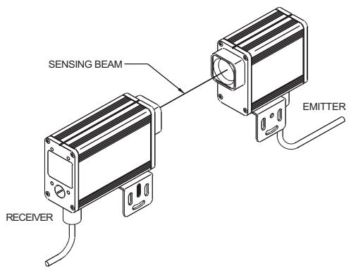
Figure 2-1 Typical Installation
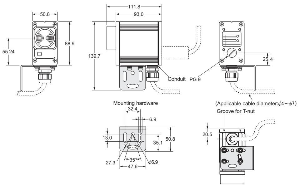
Figure 2-2 System Drawing
Figure 2-3 Indication position
Figure 2-4 Switch and Terminal block position
3 Description of Controls
3-1 Access to Controls
All switches and terminal blocks located on internal printed circuit assemblies (PCA) are accessed by removing the four captive screws which hold the emitter and receiver rear covers in place. For ease of access the PCA will slide approximately 1/2 way out of the housing. A stop is installed to keep the PCA from sliding completely out of the housing.
On emitter and receiver models two ports, threaded PG9 are provided for entry of cables. One is on the bottom surface and one is on the rear cover. A threaded plug is provided for the unused port.
3-1-1 Emitter Indicator Lights
The front panel of the emitter has two indicator lights:
| Amber | Indicates that the emitter has powered-up correctly. |
| Red | Indicates that a emitter fault (DIP switch set to invalid setting or changed after power-up) was detected after application of power. |
3-1-2 Receiver Indicator Lights
The front panel of the receiver has four indicator lights:
| Green | Run. The infrared beam is not interrupted. |
| Red | Stop. The infrared beam has been interrupted or is out of alignment. |
| Yellow | Interlock. The system has interlocked. The fault must be corrected before the system can be reset. |
| Amber | Signal Strength. For use as an alignment aid. Status interpreted as follows: Steady on: Strong Signal Strength Flashing: Weak Signal Strength Off: Out of Alignment or Beam Blocked. A flashing signal strength indicator may be acceptable at long range or when using mirrors in an installation. |
The rear panel of the receiver has two diagnostic indicator lights labeled F1 and F2. These lights flash at different rates to provide troubleshooting assistance. The faults indicated by the number of flashes are detailed in the troubleshooting section of this manual.
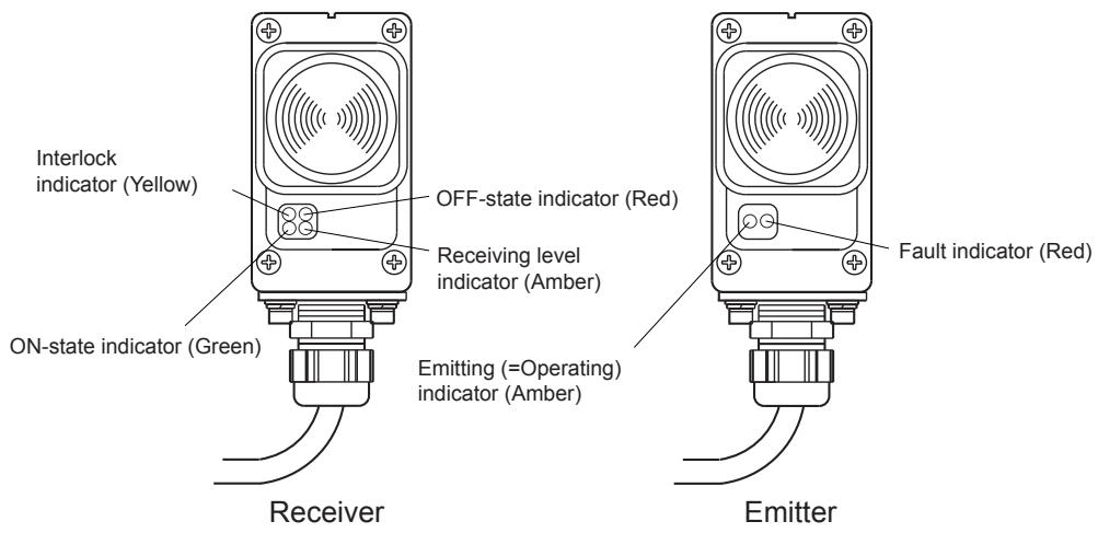
Figure 3-1
3-1-3 Receiver Operating Mode Switch
The system can be set for three possible operating modes:
| Start/Restart Interlock | Upon power-up a start signal (press & release) is required before system can enter normal operation. If the infrared beam is obstructed, the output relays will not reset after a beam obstruction is removed until a start signal has been given to the receiver. This is the mode most often used for perimeter guarding. |
| Start Interlock Mode | Upon power-up a start signal (press & release) is required before system can enter normal operation. If the infrared beam is obstructed, the output relays will reset after a beam obstruction is removed, without requiring a start signal. |
| Automatic Restart | Upon power-up the system will enter normal operation. If the infrared beam is obstructed, the output relays will reset after a beam obstruction is removed, with-out requiring a start signal. |
Details on operating mode set-up are given in the installation section.
3-1-4 Emitter and Receiver Code Switches
The infrared beam from a F3SS emitter must be set for one of four possible codes. The beam is coded to avoid cross talk from adjacent units and improve immunity to weld flash and sources of ambient light.
Both the emitter and receiver must be set to the same code in order to "talk" with one another. See installation section for switch setting details.
3-1-5 Safety Outputs
Two safety solid-state relay outputs are provided. Each output sources (PNP) up to 0.25 Amps at 24VDC.(voltage level varies with supply voltage)
3-1-6 Remote Start Switch (optional)
The Start switch is a normally closed, momentary switch that connects between the Start and Start Return terminals of the receiver terminal block. A valid Start signal is a press and release of the switch. The receiver start circuit applies about 5mA DC current through the switch contacts and a pulse of approximately 100mA, 20mS when the switch contacts are initially closed.
- In Automatic Start mode a start switch is not required and the terminals can be left open.
- In Start Interlock and Start/Restart Interlock modes the start switch is required to exit Interlock. In all modes, a Start switch can be used to reset an interlock caused by a fault, once the fault is removed.
4 Installation
4-1 User Responsibility

WARNING
Please read this information completely before starting the installation procedure. A F3SS should only be installed, checked out and maintained by a qualified person. It is important that the user be familiar with the installation requirements, safe mounting distance, controls and features before using the F3SS.
If the F3SS is used as a safety device, the user has the responsibility to insure that applicable national, federal and local safety rules, codes and regulations are satisfied. In addition, the user should insure that all machine operators, maintenance personnel, electricians, supervisors, etc. are familiar with and understand all instructions regarding the use of the F3SS, the machinery on which it is installed and the appropriate safety regulations.
4-1-1 User Responsibility
The user has the responsibility to perform all maintenance as required by OMRON on the F3SS and to insure that the guarded machine is properly tested, guarded, and inspected as specified by its manufacturer.
4-2 Installation Procedure
It is recommended that you follow the following steps be taken when installing a F3SS system:
- Carefully read and follow the information presented in Section 1-Significant Features and Requirements of this manual.
- Calculate the minimum safe mounting distance to place the F3SS away from the point of hazardous operation. Also, perform calculation to assure that reflective surface interference will not create a safety hazard.
- Select and set emitter and receiver to proper transmit code and operating mode.
- Mount emitter and receiver where determined in step 2.
- Make proper electrical and control connections.
- Apply power and align
- Test F3SS for proper operation. See Checkout and Test Procedure Logs in Appendix A
4-3 Perimeter Guarding Special Requirements
Perimeter guarding is a common application for the F3SS and refers to an installation where a F3SS is generally positioned around the outside perimeter of a machine or robot to be guarded. This could leave sufficient space for an operator to stand between the F3SS and the machine.
For perimeter guarding installation, the guarded machine or robot must be wired such that any detected interruption of the F3SS beam will cause an immediate stop of the hazardous motion. The machine or robot must only be restarted by the actuation of a start switch. This start switch must be located outside the area of hazardous motion and positioned such that the hazardous area can be observed by the switch operator. This would prevent a machine from automatically restarting once the obstruction is no longer detected by the F3SS.

WARNING
Perimeter guarding installations must not allow a machine or robot to restart automatically. Use a start switch placed outside and within view of the hazardous area.
4-4 Minimum Safe Mounting Distance and Mounting Height

WARNING
The proper calculation of the safe mounting distance is an important installation step. Never just install a F3SS at any convenient location without regard to the safety distance. If the emitter and receiver are mounted too close to the point of operation hazard, the machine may not stop in time to prevent operator injury.
The best information available on safe mounting distance and mounting height comes from the preliminary European standard EN999:1998 sections 6.1.4 and 6.1.5.
Section 6.1.5 suggests that single height beams should only be considered where they are parallel to the ground and the beam is broken by a person's body in the upright position.
Where the risk assessment allows a single height beam to be used alone then the minimum distance shall be calculated using the following formula:
S = the minimum distance from the danger zone to the detection point, line, plane or zone;
K = a parameter in mm(inches) per second, derived from data on approach speeds of the body or parts of the body. It is recommended that a minimum value of 1600mm/sec(63 in/sec) be used. Faster speeds may be warranted. To quote from ANSI standard B11.19-1990, "The value of the hand speed constant, K , has been determined by various studies and although these studies indicate speed of 1600mm/sec(63 in/sec) to over 2450mm/sec(100 in/sec), they are not considered conclusive determinations. The user should consider all factors, including the physical ability of the operator, when determining the value of K to be used."
T = the overall system stopping performance(second). T must include the response time of controls, clutches, braking systems and the F3SS (35 mS) and the time for the machine to cease hazardous motion. Add a percentage increase factor as recommended by the machine manufacturer, to allow for deterioration of the clutch and braking system.
C = an additional distance in mm(inches), based on intrusion towards the danger zone prior to the actuation of the protective equipment. In the case of the F3SS, 1200mm(48 inches)
Example:
$$ \begin{array}{l} S = (1 6 0 0 m m / s e c \times 0. 2 5 0 s e c) + 1 2 0 0 m m \ = 4 0 0 \mathrm {m m} + 1 2 0 0 \mathrm {m m} \ = 1 6 0 0 \mathrm {m m} (6 3. 7 5 \mathrm {i n}) \ \end{array} $$
When using a single beam, a mounting height of 750mm(29 inches) from the ground or reference plane has been found in industry to be a practical solution to the problems of inadvertent access from stepping over or bending under the beam.
When multiple single beams are employed, the following table presents beam mounting heights which have been found to be practical in application:
Table 4-1 Practical Beam Mounting Heights
| Number of Beams | Heights above reference plane, such as floor: mm(inches) |
| 2 | 400, 900(16, 36 ) |
| 3 | 300, 700, 1100(12, 28, 43 ) |
| 4 | 300, 600, 900, 1200(12, 24, 36, 48 ) |
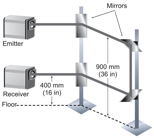
Figure 4-1 Installation Example Using Mirrors
4-5 Switch Settings
4-5-1 Emitter and Receiver Code Switches
Both the emitter and the receiver must be set to the same code. Switch settings other than those given below will result in a fault condition.
| Code # | Emitter Dip Switch | Receiver Dip Switch Position | |||||
| Position (SW1) | (SW1) | (SW2) | |||||
| 2 | 3 | 4 | 3 | 4 | 3 | 4 | |
| A | OFF | OFF | OFF | OFF | OFF | OFF | OFF |
| B | OFF | ON | ON | ON | OFF | ON | OFF |
| C | ON | OFF | ON | OFF | ON | OFF | ON |
| D | ON | ON | OFF | ON | ON | ON | ON |
4-5-2 Operating Mode Switches
Operating modes are described on page "Receiver Operating Mode Switch" on page 5. Positions 1 & 2 on SW1 and SW2 in the receiver are used to set the operation mode. Switch settings are given below:
| Receiver DIP Switch Position (SW1 & SW2) | ||
| Operating Mode | 1 | 2 |
| Automatic Start | ON | ON |
| Start Interlock | OFF | ON |
| Not Valid | ON | OFF |
| Start/Restart Interlock | OFF | OFF |
When determining which operating mode to select, it may be helpful to consult the functional flow charts which follow.
START/RESTART INTERLOCK FUNCTION
| F3SS Status | Indicators | Solid-State Safety Output Current Source | ||||
| Run Green | Stop Red | Interlock Yellow | Align Amber | |||
| Power Off | Power Supply "Off" | ○ | ○ | ○ | ○ | Off |
| Apply Power | Power-Up Inhibit Condition | ○ | ○ | ○ | Steady or Flashing | Off |
| Open and then Close Start Switch Contacts | Restart Signal | ○ | ○ | ○ | On | |
| Machine MPCE Contacts Close Machine Start | Sensing Beam Clear Machine Run | ○ | ○ | ○ | On | |
| Machine Run | Machine Run Condition | ○ | ○ | ○ | On | |
| Interrupt Sensing Beam | Sensing Beam Restricted Guard Interlock Condition | ○ | ○ | ○ | ○ | Off |
| Machine MPCE Contacts Open Machine Stop | Sensing Beam Restricted Guard Interlock Condition | ○ | ○ | ○ | ○ | Off |
| Sensing Beam Clear | Reset of Restart Interlock (rerquires Restart before machine will run) | ○ | ○ | ○ | Off | |
| Open and then Close Start Switch Contacts | Restart Signal (resumes Machine Run condition) | ○ | ○ | ○ | On | |
Figure 4-2 Start/Restart Interlock Mode Functional Flow Chart
START INTERLOCK MODE FUNCTION
| F3SS Status | Indicators | Solid-State Safety Output Current Source | ||||
| Run Green | Stop Red | Interlock Yellow | Align Amber | |||
| Power Off | Power Supply "Off" | ○ | ○ | ○ | ○ | Off |
| Apply Power | Power-Up Inhibit Condition | ○ | ○ | ○ | Steady or Flashing | Off |
| Open and then Close Start Switch Contacts | Restart Signal | ○ | ○ | ○ | On | |
| Machine MPCE Contacts Close Machine Start | Sensing Beam Clear Machine Start | ○ | ○ | ○ | On | |
| Machine Run | Machine Run Condition | ○ | ○ | ○ | On | |
| Interrupt Sensing Beam | Sensing Beam Blocked | ○ | ○ | ○ | ○ | Off |
| Machine MPCE Contacts Open Machine Stop | Sensing Beam Blocked | ○ | ○ | ○ | ○ | Off |
| Sensing Beam Clear | Sensing Beam Clear | ○ | ○ | ○ | On | |
Figure 4-3 Start Interlock Mode Functional Flow Chart
AUTOMATIC START FUNCTIONAL FLOW CHART
Figure 4-4 Automatic Start Mode Functional Flow chart
| F3SS Status | Indicators | Solid-State Safety Output Current Source | ||||
| Run Green | Stop Red | Interlock Yellow | Align Amber | |||
| Power Off | Power Supply "Off" | ○ | ○ | ○ | ○ | Off |
| Apply Power | Power-Up | ○ | ○ | ○ | Steady or Flashing | On |
| Machine MPCE Contacts Close Machine Start | Sensing Beam Clear Machine Start | ○ | ○ | ○ | On | |
| Machine Run | Machine Run Condition | ○ | ○ | ○ | On | |
| Interrupt Sensing Beam | Sensing Beam Restricted | ○ | ○ | ○ | ○ | Off |
| Machine MPCE Contacts Open Machine Stop | Sensing Beam Restricted | ○ | ○ | ○ | ○ | Off |
| Sensing Beam Clear | Sensing Beam Clear | ○ | ○ | ○ | On | |
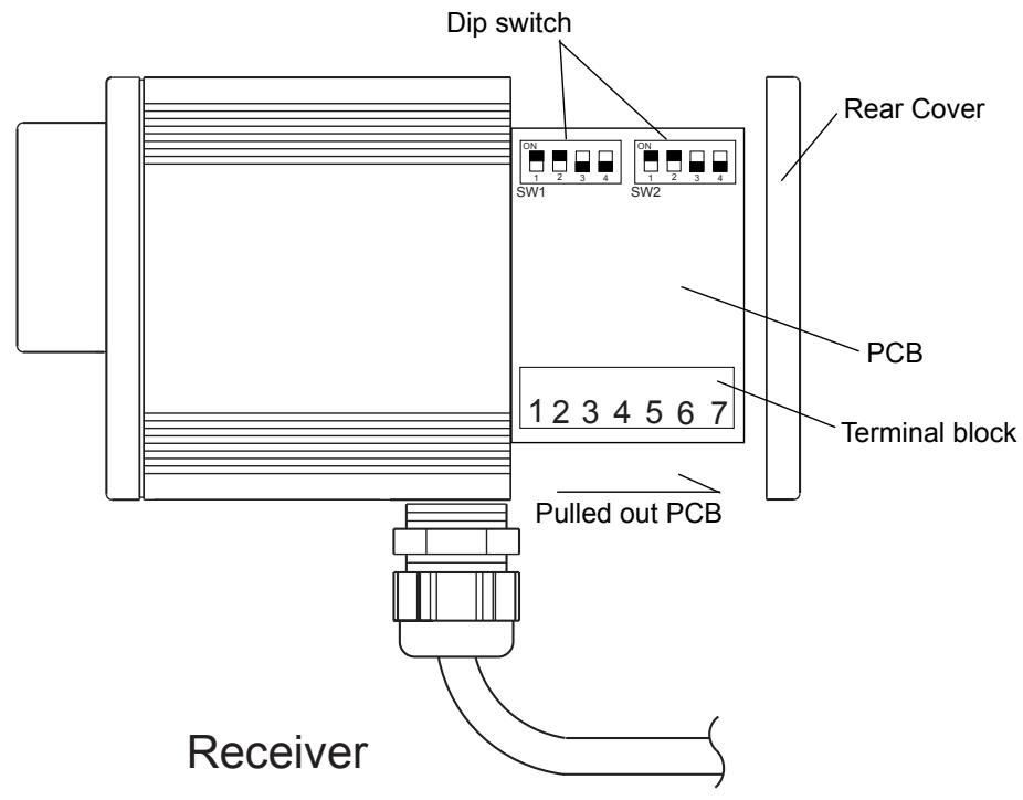
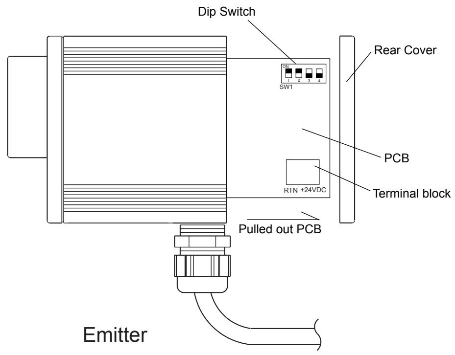
Figure 4-5 Switches and Terminals
4-6 Electrical Connections

WARNING
All electrical connections must be made by qualified personnel only and in accordance with local and national electrical codes and regulations. Shut off all power to the machine and the controller before connecting. Never allow any metal filings or chips to enter a F3SS enclosure and possibly impair the function of the F3SS.
Hint: When wiring to F3SS components, leave the wires just long enough to allow the printed circuit board to be withdrawn to the extent allowed by its stops. For ease of connection and servicing, OMRON recommends the use of 18 AWG wire when connecting the F3SS to a machine control system.
4-6-1 Emitter Electrical Connections
The only connections which can be made inside the emitter are those for input power. Terminals for input power are provided on terminal block J3 at the bottom of the board. The printed circuit boards are labeled for proper connection.
Table 4-2 Emitter Terminal Block
| Terminal Block | Terminal Name | Function | Terminal Block Illustration |
| J3 | +24VDC | +24VDC | Terminal Block as viewed from top/front |
| RTN | 0V (GND) | RTN +24VDC |
4-6-2 Receiver Electrical and Control Connections
Control and electrical connections are made inside the receiver on terminal block J5 at the bottom corner of the board. Terminal positions and functions are as follows:
Table 4-3 Receiver Terminal block
| Terminal Block | Terminal Number | Function | Terminal Block Illustration |
| J5 | 1 | Output 1 (+) | Terminal Block viewed from top/front |
| 2 | Output 1/2 (-) | ||
| 3 | Output 2 (+) | ||
| 4 | Start (-) | ||
| 5 | Start (+) | ||
| 6 | +24 VDC | ||
| 7 | 0V (GND) |
4-6-3 Long cable length installation for Receiver
For a receiver installed with a cable greater than 9mm(30 feet) in length and a load of less than 50mA . A load resistor, 1 K ohm, 1 watt (provided in hardware kit) must be installed between the output (+) and output (-) at the destination point of the solid-state output.
4-6-4 Safety Earth Connections
Both emitter and receiver must be grounded to maintain EMC immunity. This is accomplished by attaching the safety earth wire to the inside of the emitter and receiver housing using the supplied ring lug and securing it under the supplied bolt and washer which fastens to a T-nut. A 8mm(5/16 inch) box wrench is helpful in performing this operation.
4-7 Machine Control Circuit Connections

WARNING
Contact the protected machine manufacturer for assistance on how to wire a F3SS to the machine control circuit. It is critical that the F3SS be properly connected or it will not provide maximum protection to the machine operators and could result in serious injury. The machine control circuit wiring is the sole responsibility of the employer.
4-7-1 Solid-state Output Connection
This unit supplies two solid-state outputs. Each output sources (PNP) up to 0.25 Amps at 24VDC.
Each solid-state output is monitored by both internal, independent micro controllers when the outputs are in the energized state. Monitoring is accomplished by momentarily pulsing the solid-state output off for a short period. The minimum pulse width is 50~ sec and the maximum is 200~ sec . The pulse width will automatically increase with an increase in the load capacitance. This test pulse occurs approximately every two minutes. Any circuit failure will be detected and both outputs will be forced to the de-energized state. T
Solid-state outputs should be connected only to a control reliable, safety rated PLC; or a control reliable safety-rated machine control system. For a definition of control reliable, see page 1.
4-7-2 Connection Method
The following connection scheme uses both output relays to control the machine. This is the preferred wiring method for all applications.
In your machine control circuit, locate the two Machine Primary Control Elements (MPCE). The method to arrest hazardous machine motion will vary depending on the type of machine. Control methodologies include hydraulic, pneumatic, clutch and mechanical braking systems. Thus there are several variations of MPCE, including relays, contactor, solenoids and electromechanical valves.
If you are unsure of the proper connection location to use for your machine control system, contact your machine manufacturer for assistance.
When using in Start Interlock Mode or Start/Restart Interlock Mode
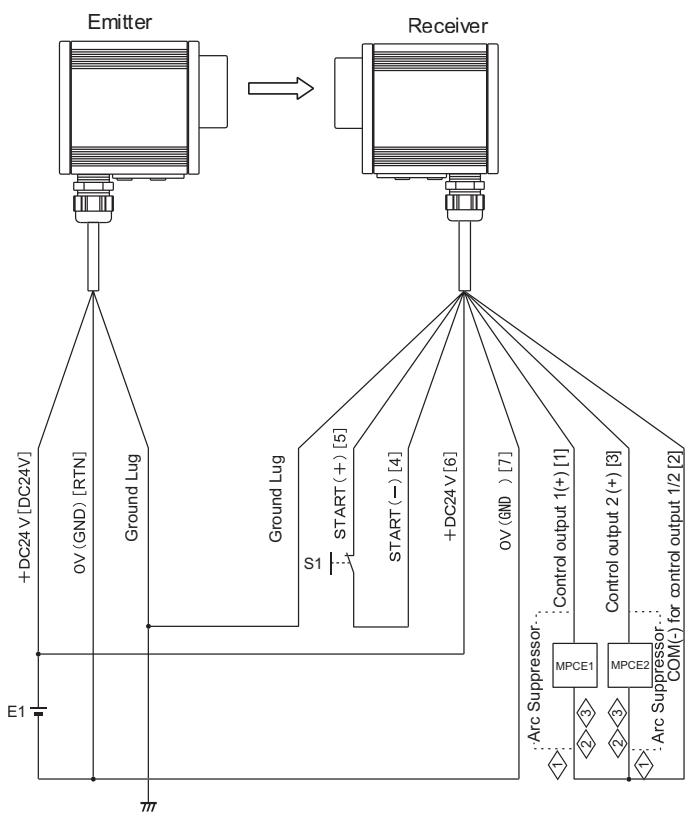
Description in square parentheses indicates terminal name or terminal number.
E1: 24VDC power supply (model S82K recommended)
S1: Start switch (for releasing interlock): NC contact
MPCE1 and MPCE2: DC-driving high sensitivity contactor (model J7AN etc.)


Figure 4-6 Connection Method(Start Interlock Mode or Start/Restart Interlock Mode)
WARNING
Arc suppression devices should only be installed across the coils of the machine control relays.
Never install Arc Suppression devices directly across the control output contacts of the F3SS. An arc suppression device installed accros the contacts may fail with a short circuit and will result in an unsafe condition.
These relay contacts must be force guided contacts.
If load is less than 50mA a resistormust be installed across the load. See page B-11.
Note: DC power supply must be isolated from the power main and other devices.
When using in Automatic Start Mode
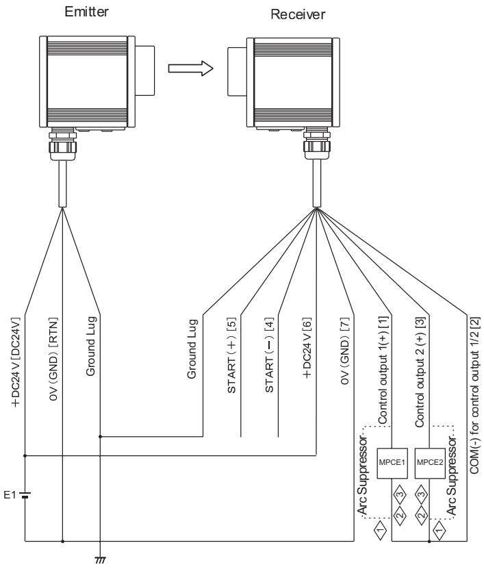
Description in square parentheses indicates terminal name or terminal number.
E1: 24VDC power supply (model S82K recommended)
MPCE1 and MPCE2: DC-driving high sensitivity contactor (model J7AN etc.)


Figure 4-7 Connection Method(Automatic Start Mode)
WARNING
Arc suppression devices should only be installed across the coils of the machine control relays.
Never install Arc Suppression devices directly across the control output contacts of the F3SS. An arc suppression device installed accros the contacts may fail with a short circuit and will result in an unsafe condition.
These relay contacts must be force guided contacts.
If load is less than 50mA a resistormust be installed across the load. See page B-11.
Note: DC power supply must be isolated from the power main and other devices.
Example of connection to Type G9SA-301 Safety Relay Unit (also applicable to category 4)
Figure 4-8 Connection Method(Example of connection to Type G9SA-301 Safety Relay Unit [also applicable to category 4])
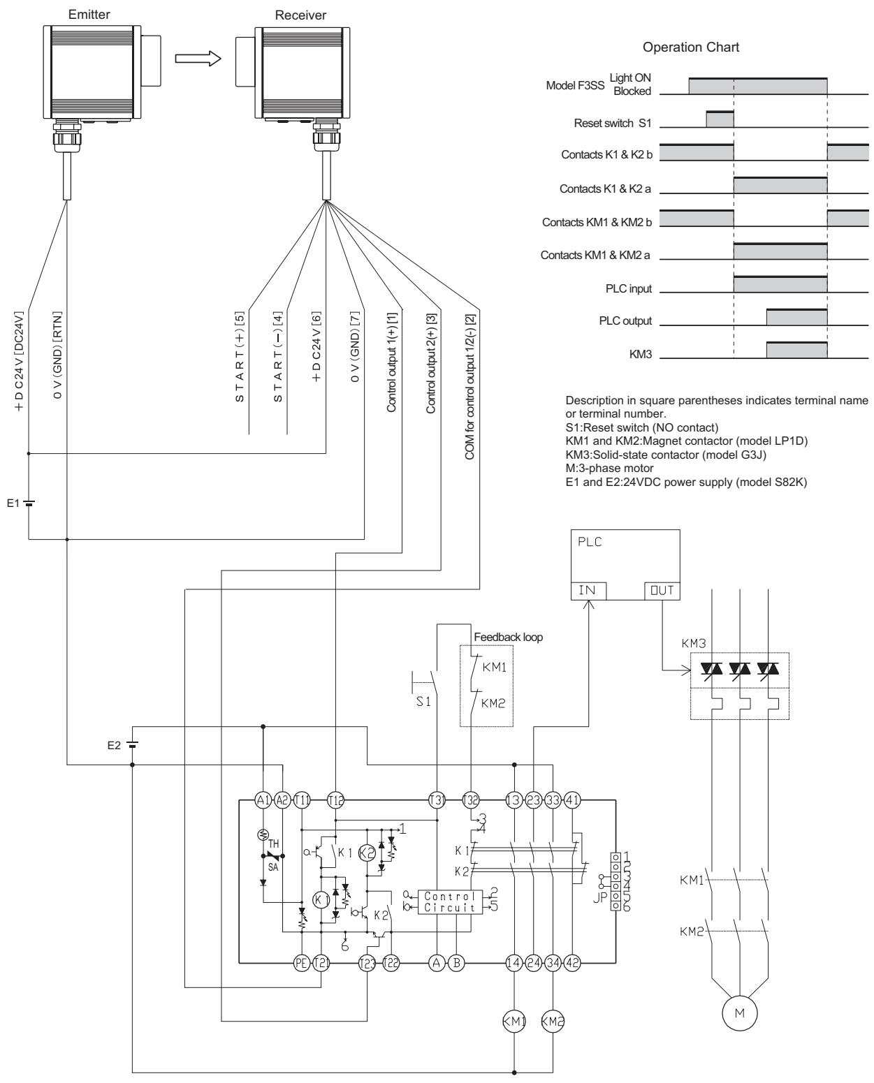
Note: When connecting the F3SS and G9SA-301 models, do not use the start/restart interlock function incorporated in the F3SS model, only use the interlock function incorporated in the G9SA-301 model.
4-8 Physical Mounting
4-8-1 Installation of Multiple F3SS Units
Figure 4-9 Unsafe Installation Method
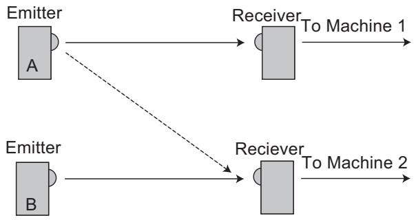
Figure 4-9 shows two emitter/receiver pairs. The pair on top is using beam code A and the pair on the bottom is using beam code B. The optical channels are indicated by solid lines. Each system is operating a different machine.
Consider the case where emitter B is obstructed. Machine 2 stops. Now emitter A switches to transmitting beam code B. This is represented by the dashed line. Machine 1 has stopped, but machine 2 has restarted, because of the optical path created by the dashed line. If two F3SS systems are installed this way, they need to control the same machine.
The preferred option is to install them so that there is no optical path corresponding to the dashed line. That could be done with the installation shown in Figure 4-10.
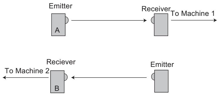
Figure 4-10 Preferred Mounting Orientation
This installation doesn't allow either receiver to see light from two emitters, making it a safe installation.
4-8-2 Reflective Surface Interference
Reflective surfaces (e.g. shiny metal, glossy paint,foil,plastic) near the infrared beam can create two paths to the receiver. Install a F3SS system so that there are no reflective surfaces within the beam angle of the emitter and receiver.
The formula for determining the safe distance from a reflective surface is:
$$ d = R / 2 (\tan 2 a) $$
Where:
$$ d = \text {m i n i m u m} $$
$$ R = \text {d i s t a n c e} $$
$$ a = \text {h a l f a n g l e o f F 3 S S} (2. 5 ^ {\circ}, \text {f o r d i s t a n c e s} > 3 \mathrm {m} (9. 8 \text {f t .})) $$
Example:
$$ R = 3 0 m $$
$$ \begin{array}{l} d = 3 0 / 2 (\tan 2 (2. 5 ^ {\circ})) \ = 1 5 \tan 5 ^ {\circ} \ = 1 5 (0. 0 8 7 5) \ = 1. 3 \mathrm {m} (4. 3 7 \mathrm {f t .}) \ \end{array} $$
The following four figures illustrate correct and incorrect mounting for reflective surfaces.
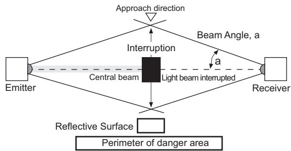
Figure 4-11 Example of correct mounting with proper alignment.
In this example, the interruption of the beam is clearly detected. The reflective object is outside of the beam angle.
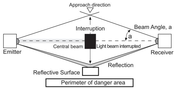
Figure 4-12 Example of Unsafe mounting
The interruption of the beam is not detected because of reflection. The reflective object is inside the beam angle.
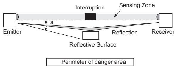
Figure 4-13 Example of Unsafe mounting
Interruption of the beam is not detected because of reflection. Reflective surfaces interference may also appear above and below the sensing beam.
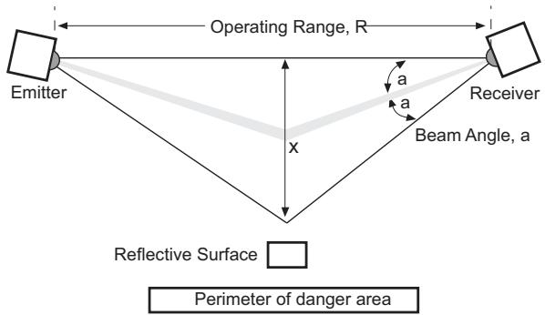
Figure 4-14 Worst Case Alignment example
This shows minimum distance from reflective surface x to one side of the beam center line.
4-8-3 Bracket Mounting Points
The bracket included with the F3SS is designed to offer a wide range of mounting options and can be attached either to the bottom of the emitter and receiver (allowing the widest range of adjustment) or directly to the back cover of either unit.

WARNING
Misalignment may increase reflective surface interference. Physical alignment of the emitter and receiver should be performed carefully upon installation, and checked periodically thereafter.
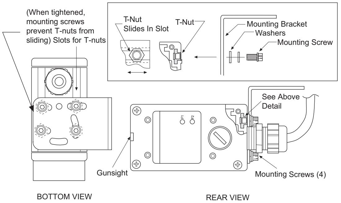
Figure 4-15 Mounting Bracket
4-8-4 Alignment
Two aids have been provided on the F3SS to assist with long-range alignment.
A "gunsight" device has been designed into the top of the emitter and receiver housing to aid in physical alignment.
Additionally, the receiver has an amber-color visible alignment indicator which provides the following informational.
Table 4-4 Alignment indicator light
| If the amber light is: | This indicates: |
| Steady On | Strong Signal |
| Flashing | Weak Signal |
| Off | Out of Alignment or beam blocked |
Note: Where used with mirrors it is recommended to use the optional laser alignment tool, F39-LLK, to ease alignment.
5 Troubleshooting and Maintenance
5-1 Troubleshooting
Two diagnostic indicators labeled F1 and F2 are located on the back cover of the receiver. These indicators will flash a discrete number of flashes to indicate the possible source of a problem. Only those codes which can assist the user in correcting a fault are listed in the following text.
Table 5-1 Troubleshooting with F1 and F2 flashing indicators
| Number of Flashes on F1 or F2 | Fault Description | Suggested Solution |
| 1 | More than one valid transmit code detected by receiver | Check codes of adjacent systems. Set to different codes |
| 2 or 9 | Code or mode not valid at power up | Check settings on internal DIP switches. Set to valid setting. |
| 3 | Any DIP switch changed after power applied. Invalid DIP switch setting. | Check DIP switch settings. Remove and reapply power. |
| 5 | Output relay not properly responding. | Check output relays. If replacement is needed return unit to OMRON. |
| All Other codes | Fault is not user serviceable. | Consult OMRON |
5-2 Maintenance
The Checkout Procedure (Appendix B) should be performed at least every three months or more frequently depending on machine usage. Only qualified personnel should perform the procedure. Inspection logs should be kept with the machine records.
Oil, dust and grease can build up on the plastic lens of the emitter and receiver and can affect operation of the F3SS. A periodic cleaning will prevent these problems. Clean the lenses with a mild detergent or glass cleaner. Use a clean, soft, lint-free cloth or wipe to dry. Painted surfaces may be cleaned with a mild degreasing cleaner or detergent.
6 Accessories
6-1 Accessories
Table 6-1 Accessories for F3SS
| Model Number | Description |
| F39-MSG | Front Surface Glass Mirror |
| F39-MSS | Polished Stainless-steel Mirror |
| F39-LM45 | Bracket for mounting above mirrors at 45° angle |
| F39-LLK | Laser Alignment Tool |
| F39-LSP | Mounting kit for F3SS sensor |
| F39-LA | Mounting kit for F39-MSG or F39-MSS mirror |
Appendix A –Test Procedures
A-1 Tests To Perform
The following tests must be performed at installation and after any maintenance, adjustment, repair or modification to the F3SS or the machine. Testing ensures that the F3SS and the machine control system work properly to stop the machine. Failure to test properly could result in serious injury to personnel.
The following Test Procedure must always be performed by qualified personnel after the mounting, alignment and wiring steps are completed and before the F3SS is used to control the machine. To test the F3SS, use an opaque object of the appropriate size.
| Item | Condition | Comments |
| 1.Disable the machine to be guarded. Turn power on to the F3SS. | ☐ Pass☐ Fail | |
| 2.Visually inspect the machine to ensure that entry to the hazardous area is only through the F3SS sensing beam. If not, additional guarding including mechanical barriers may be required. Verify that all additional guarding devices and barriers are installed and operating properly. | ☐ Pass☐ Fail | |
| 3.Verify that the mounting distance of the F3SS is equal to or greater than the calculated maximum safe distance from the point of hazardous operation. | ☐ Pass☐ Fail | |
| 4.Check for signs of external damage to the F3SS, the machine and the electrical cables and wiring. If any damage is found, lockout the machine and report to the supervisor. | ☐ Pass☐ Fail | |
| 5.Next, interrupt the sensing beam with a proper size test object to check the effectiveness of the F3SS. Verify that the red indicator is on and the green indicator is off while the test object is anywhere in the sensing beam. Also, watch for any unprotected access to the danger point. | ☐ Pass☐ Fail | |
| 6.Start the machine. While the machine is in motion, interrupt the sensing beam with a test object. The machine should stop immediately. Never insert the test object into the dangerous parts of the machine. With the machine at rest, interrupt the sensing field with the test object. Verify that the machine will not start with the test object in the sensing beam. | ☐ Pass☐ Fail | |
| 7.Make sure that the braking systems working properly. If the machine does not stop fast enough, adjust the braking system or increase the distance from the sensing beam to the point of operation hazard. | ☐ Pass☐ Fail | |
| 8.If the safety devices or the machine fails any of these test, do not run the machine. Immediately tag or lockout the machine to prevent its use and notify the supervisor. | ☐ Pass☐ Fail |
Comments:

WARNING
The F3SS should be tested by breaking the beam at least once per shift or every 24hours at minimum.

WARNING
If the F3SS and machinery did not function exactly as described in the Test Procedure, do not operate the machinery. If the machine safety devices, braking systems and controls do not operate properly, they cannot stop hazardous machine motion. Serious injury to personnel could result.
Appendix B –Checkout Procedure
B-1 Checkout Procedure Log
The following Checkout Procedure must be performed by qualified personnel during initial F3SS installation and at least every three months or more frequently depending on a machine usage and company guidelines.
Hint: make a copy of the checkout procedure form and use the copy as the checkout log to be kept with the machine records. Use caution when working around hazardous voltages which may be present during this procedure.
Machine Identification: Date:
| Item | Condition | Comments |
| 1.Verify the guarded machine is compatible with the type of machine which may be used with a F3SS. | ☐ Pass☐ Fail | |
| 2.Verify that the mounting distance of the F3SS is equal to or greater than the minimum safe distance from the point of operation. | ☐ Pass☐ Fail | |
| 3.Determine that all access to the danger point not protected by a F3SS are guarded by other means, such as gates, fencing, wire screening or other approved methods. Verify that all additional guarding devices, inter-lock switches and mechanical barriers are installed and operating properly. | ☐ Pass☐ Fail | |
| 4.Verify that the F3SS can only be reset from a position outside and within the view of the hazardous machine area. | ☐ Pass☐ Fail | |
| 5.Inspect the electrical connections between the guarded machine control circuitry and the F3SS. Verify that they are properly connected to the machine such that a stop signal from the F3SS results in an immediate halt at any point in the machine's cycle or stroke. | ☐ Pass☐ Fail | |
| 6.Record the test results in the machine log. Next, perform the Test Procedure. | ☐ Pass☐ Fail |
Comments:
Technician Signature:
- Single Beam Safety Sensor
- INSTRUCTION MANUAL
- Introduction
- Regulations and Standards
- Notice
- Precaution on Safety
- General conventions for safe use
- Table of Contents
- Significant Features and Requirements 1
- Theory of Operation 2
- Description of Controls 4
- Installation 6
- Troubleshooting and Maintenance 20
- Accessories 21
- Appendix A - Test Procedures 22
- Appendix B -Checkout Procedure 24
- Significant Features and Requirements
- 1-1 F3SS General Description
- 1-2 Meeting Full Compliance
- 1-3 Employer Responsibilities
- 1-3-1 Additional Requirements
- Theory of Operation
- 2-1 F3SS System Specifications
- 2-1-1 Technical Specifications*
- Description of Controls
- 3-1 Access to Controls
- 3-1-1 Emitter Indicator Lights
- 3-1-2 Receiver Indicator Lights
- 3-1-3 Receiver Operating Mode Switch
- 3-1-4 Emitter and Receiver Code Switches
- 3-1-5 Safety Outputs
- 3-1-6 Remote Start Switch (optional)
- Installation
- 4-1 User Responsibility
- WARNING
- 4-1-1 User Responsibility
- 4-2 Installation Procedure
- 4-3 Perimeter Guarding Special Requirements
- 4-4 Minimum Safe Mounting Distance and Mounting Height
- 4-5 Switch Settings
- 4-5-1 Emitter and Receiver Code Switches
- 4-5-2 Operating Mode Switches
- 4-6 Electrical Connections
- 4-6-1 Emitter Electrical Connections
- 4-6-2 Receiver Electrical and Control Connections
- 4-6-3 Long cable length installation for Receiver
- 4-6-4 Safety Earth Connections
- 4-7 Machine Control Circuit Connections
- 4-7-1 Solid-state Output Connection
- 4-7-2 Connection Method
- 4-8 Physical Mounting
- 4-8-1 Installation of Multiple F3SS Units
- 4-8-2 Reflective Surface Interference
- 4-8-3 Bracket Mounting Points
- 4-8-4 Alignment
- Troubleshooting and Maintenance
- 5-1 Troubleshooting
- 5-2 Maintenance
- Accessories
- 6-1 Accessories
- Appendix A –Test Procedures
- A-1 Tests To Perform
- Appendix B –Checkout Procedure
- B-1 Checkout Procedure Log
Brand : OMRON
Model : F3SS
Category : Proximity sensor