
E3M-V - Proximity sensor OMRON - Free user manual and instructions
Find the device manual for free E3M-V OMRON in PDF.


| Product type | Proximity sensor (mark detector) |
| Brand | OMRON |
| Model | E3M-V |
| Detection distance | 10 ± 3 mm |
| Spot size (width × height) | 1 × 4 mm or 4 × 1 mm depending on version |
| Light source | Green LED (525 nm) |
| Supply voltage | 10 to 30 VDC (residual ripple ≤ 10%) |
| Current consumption | 100 mA max. |
| Output type | NPN or PNP (open collector) |
| Response time | ON: 50 μs max., OFF: 70 μs max. |
| Protection rating | IP67 (with protective cap) |
| Weight (with packaging) | Approx. 100 g |
| Housing material | Polybutylene terephthalate (PBT) |
| Lens material | Acrylic (PMMA) |
| Operating temperature | -20 °C to 55 °C (no frost) |
| Operating humidity | 35% to 85% (no condensation) |
| Teaching functions | Auto-teaching, one-point teaching, two-point teaching, remote control |
| Indicators | 8 detection level indicators (green), 7 threshold indicators (red) |
| Connection | Rotatable M12 connector or pre-wired cable (2 m) |
| Supplied accessories | Instruction manual, mounting brackets (optional) |
| Cable length (pre-wired models) | 2 m (standard) |
| Repairability | Not user-repairable. Do not disassemble, repair, or modify. |
| Maintenance and cleaning | Clean the lens with a soft, non-abrasive cloth. Do not use solvents. |
| Safety | Do not use in explosive or flammable atmospheres. Observe the power supply polarities. |
Frequently Asked Questions - E3M-V OMRON
User questions about E3M-V OMRON
0 question about this device. Answer the ones you know or ask your own.
Ask a new question about this device
Download the instructions for your Proximity sensor in PDF format for free! Find your manual E3M-V - OMRON and take your electronic device back in hand. On this page are published all the documents necessary for the use of your device. E3M-V by OMRON.
USER MANUAL E3M-V OMRON
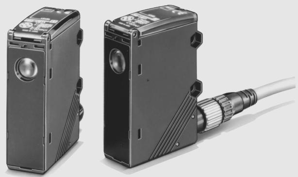
- Detects laminated or light-dispersing objects in stable operation without being influenced by mirror reflection.
- Double indication of the detection level and threshold level allows easy grasp of the operating status and easy adjustment.
- Automatically sets to the optimum threshold level while sensing objects are being conveyed and incorporates an auto-teaching function that discriminates between the mark and background and turns ON when the mark is detected.
- IP67 watertight construction with M12 rotary connector
- High response speed of 50 s and half the size of OMRON's conventional models.
C E
Applications
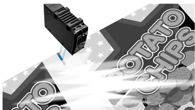
Dependably Detects Marks on Laminated Sheets
The coaxial optical system ensures a long sensing distance and stable sensing characteristics over a wide angle range, even for objects that are distance-fluctuating or leaning at an angle, or for laminated objects with marks, which conventional models have difficulty in detecting
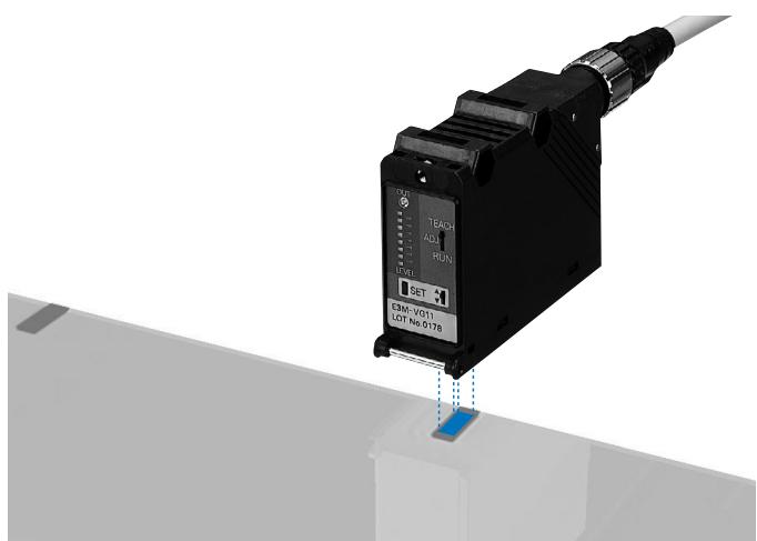
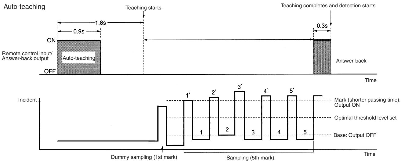
Auto-Teaching
An auto-teaching function automatically sets the threshold value upon a Remote Control input while the workpiece is moving.
There is no need to position the mark at the optical spot.
Ordering Information
Sensors
| Shape | Connection method | Setting distance | Spot diameter | Model | |
| NPN output | PNP output | ||||
| Connector type1 | 10+3 mm | 1 x 4 mm | E3M-VG11 | E3M-VG16 | |
| 4 x 1 mm | E3M-VG21 | E3M-VG26 | |||
| Pre-wired | 1 x 4 mm | E3M-VG12 | E3M-VG17 | ||
| 4 x 1 mm | E3M-VG22 | E3M-VG27 | |||
- Possible to switch between vertical or horizontal connection using the M12 rotary connector
Mounting Brackets
| Shape | Model | Quantity | Remarks |
| E39-L131 | 1 | ||
| E39-L132 | 1 | For rear mounting |
Sensor I/O Connectors
| Shape | Type | Cord type | Model | |
| Single-end connector (Straight) | 2 m | 4-wire cord | XS2F-D421-D80-A | |
| 5 m | XS2F-D421-G80-A | |||
| Single-end connector (L-shaped) | 2 m | XS2F-D422-D80-A | ||
| 5 m | XS2F-D422-G80-A | |||
Ratings/Characteristics
| Item | E3M-VG11 | E3M-VG12 | E3M-VG21 | E3M-VG22 | E3M-VG16 | E3M-VG17 | E3M-VG26 | E3M-VG27 |
| Sensing distance | 10±3 mm | |||||||
| Spot size (W x H) | 1 x 4 mm | 4 x 1 mm | 1 x 4 mm | 4 x 1 mm | ||||
| Light source (wave-length) | Green LED (525 nm) | |||||||
| Power supply voltage | 10 to 30 VDC, ripple (p-p) 10% max. | |||||||
| Current consumption | 100 mA max. | |||||||
| Control output | Load power supply voltage: 30 VDC max. Load current: 100 mA max. (Residual voltage: 1.2 V max.) NPN open collector output type | Load power supply voltage: 30 VDC max. Load current: 100 ma max. (Residual voltage: 2 V max.) PNP open collector output type | ||||||
| Remote control input1 | ON: Short-circuited to 0 or 1.5 V max. (with a flow current of 1 mA max.) OFF: Open or Vcc - 1.5 V to Vcc (with a leakage current of 0.1 mA max.) | ON: Vcc - 1.5 V to Vcc (with an absorption current of 3 mA max.) OFF: Open or 1.5 V max. (with a leakage of 0.1 mA max.) | ||||||
| Remote control output1 | Load power supply voltage: 30 VDC max. Load current: 100 mA max. (Residual voltage: 1.2 V max.) NPN open collector output type | Load power supply voltage: 30 VDC max. Load current: 100 ma max. (Residual voltage: 2 V max.) PNP open collector output type | ||||||
| Bank selection | Two banks selectable. Available for remote control only. (Refer to Remote Control Function.) | |||||||
| Circuit protection | Protection from reversed power supply connection and load short-circuit | |||||||
| Response time | ON: 50 μs max. OFF: 70 μs max. | |||||||
| Ambient illumination (on receiver lens) | Incandescent lamp: 3,000lx max. Sunlight: 10,000lx max. | |||||||
| Ambient temperature | Operating: -20°C to 55°C/Storage: -30°C to 70°C (with no icing) | |||||||
| Ambient humidity | Operating: 35% to 85%/Storage: 35% to 95°C (with no condensation) | |||||||
| Insulation resistance | 20 M min. (at 500 VDC) | |||||||
| Dielectric strength | 1,000 VAC, 50/60Hz, 1 min. | |||||||
| Vibration resistance2 | Destruction: 10 to 55 Hz, 1-mm double amplitude or 150 m/s2 for 2 hrs each in X, Y, and Z directions | |||||||
| Shock resistance3 | Destruction: 500 m/s2 3 times each in X, Y, and Z directions | |||||||
| Degree of protection | IEC60529 IP67 (with protective cover) | |||||||
| Connection method | Connector | Pre-wired | Connector | Pre-wired | Connector | Pre-wired | Connector | Pre-wired |
| Weight with package box | Approx. 100 g | |||||||
| Material | Case: Polybutylene terephthalate Lens: Acrylic (PMMA) | |||||||
| Others | Instruction manual | |||||||
- Remote control input and answer-back output share the same signal line.
- The Sensor withstands 0.75mm double amplitude or 100m / s^2 if the mounting bracket is attached to the sensor
- The Sensor withstands 300m / s^2 if the mounting bracket is attached to the sensor.
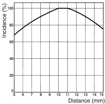
Sensing Distance vs. Incident Characteristics (Typical) E3M-VG1
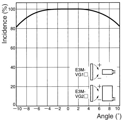
Angle vs. Incident Characteristics (X Direction) E3M-VG1VG2

Angle vs. Incident Characteristics (Y Direction) E3M-VG1VG2
Color Sensing Capacity E3M-VG
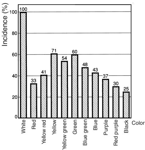
Differences in Incident by Color
Technical Guide
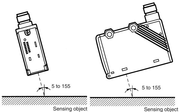
Glossy Sensing Objects
Incline the Sensor to detect glossy objects so that the Sensor will not be influenced by the mirror reflection of light and to ensure the stable sensing operation of the E3M-V.
Standard Sensing Object (Color vs. Munsell) Japan Color Enterprises Standard Color Card 230
| 11 standard colors | Munsell color notation |
| White | N9.5 |
| Red | 4R, 4.5/12.0 |
| Yellow red | 4YR, 6.0/11.5 |
| Yellow | 5Y, 8.5/11.0 |
| Yellow green | 3GY, 6.5/10.0 |
| Green | 3G, 6.5/9.0 |
| Blue green | 5BG, 4.5/10.0 |
| Blue | 3PB, 5.0/10.0 |
| Purple | 7P, 5.0/10.0 |
| Red purple | 6RP, 4.5/12.5 |
| Black | N2.0 |
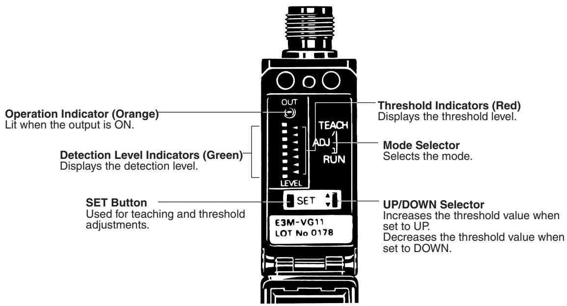
Operation
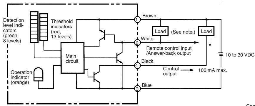
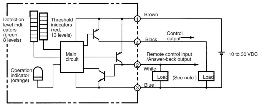
Output Circuits
NPN (E3M-VG11, E3M-VG12, E3M-VG21, E3M-VG22)
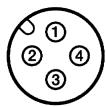
Connector Pin Arrangement
PNP (E3M-VG16, E3M-VG17, E3M-VG26, E3M-VG27)
Adjustments
Adjustment Steps
- Install, wire, and turn ON the Photomicrosensor.
- Perform teaching (mark registration). Refer to Mark Registration (Teaching).
Mark Registration (Teaching)
Refer to the following for ideal teaching.
| Application | ||
| The base has a color pattern. The mark and base are clearly different in color. | The base has no color pattern. The mark and base are slightly different in color. | The base has no color pattern. Remote teaching with no positioning is desired. |
| One-point teaching | Two-point teaching | Auto-teaching |
| The default level is set and the output is ON when the mark is detected. | The threshold level is set between the color of the mark and base. The output is ON when the mark is detected. | The threshold level is set between color of the mark and base. The output is ON when the mark (i.e., the color with shorter passing time) is detected. |
Refer to the following for each teaching method. Remote one- or two-point teaching is possible. Refer to Remote Control Function.
One-point Teaching
1 Set the mode selector to TEACH.
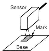
2 Locate the mark to the sensing position and press the SET button. Then all the red threshold indicators are ON.
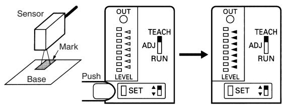
Red threshold indicators are ON.
3 Set the mode selector to RUN. The output will be ON whenever the set mark is detected.
Note: By teaching on the base, reversed output as shown above (base: ON, mark: OFF) can be obtained.
- Make fine adjustments of the threshold level if necessary. Refer to Threshold Level Adjustments on page A-139.
- Check that the mode selector is set to RUN.
Two-point Teaching
1 Set the mode selector to TEACH.
2 Locate the mark to the sensing position and press the SET button. All the red threshold indicators will turn ON.
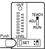
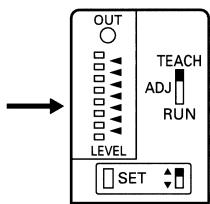
Red threshold indicators are ON.
3 If teaching is successful, move the mark and press the SET button at the base.
- If teaching is successful, all the green detection level indicators are ON.
- If teaching is unsuccessful, all the red threshold level indicator flash.
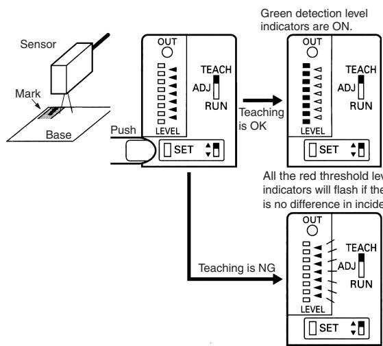
4 If teaching is successful, set the mode selector to RUN to complete the teaching operation. If teaching is unsuccessful, restart from the above step 2.
Note: Follow the above steps so that the output will be turned ON whenever the mark is detected. By taking the opposite steps, the output will be turned OFF whenever the mark is detected and turned ON whenever the base is detected.
Auto-teaching
- Check that the mode selector is set to either RUN or ADJUST.
- Input a 0.9-s pulse signal into the remote control I/O terminal. ^1
- Auto-teaching starts when the mark is moved. When the mark passes six times, auto-teaching completes.
If teaching is successful, answer-back output from the remote control I/O terminal will turn ON for 0.3 s.
If teaching is unsuccessful, no answer-back signal will be output. Readjust using two-point teaching.
(Teaching will be unsuccessful if there is no difference in incident between the mark and base.) - If the answer-back signal is ON, the whole teaching operation will be completed. The output will be turned ON whenever the mark (i.e., the color with shorter passing time) is detected.
Example of Connection to Programmable Controller
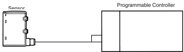
Note: Be sure to connect the E3M-V to the Programmable Controller as shown above.
Precautions when Using Automatic Teaching
Incorrect discrimination may be caused by automatic teaching in the following cases. Use one-point or two-point teaching in such cases.
Color patterns exist in the base.
- Sensing objects change their positions.
- Sensing objects have protrusions or surface level differences.
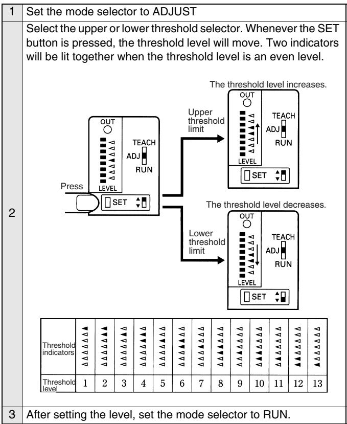
Threshold Level Adjustments
It is possible to make fine adjustments of the threshold level after teaching. Such fine adjustments can be made remotely as well. Refer to Remote control Function (Bank Selection, Mark Registration, and Threshold Adjustments) on page A-140.
Detection Level Indicator
Detection Level Indicator
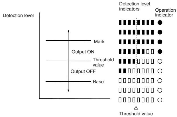
The control output of the E3M-V will be turned ON if the detection level exceeds the threshold level. The indication of the detection level varies with the teaching method.
One-point Teaching
The upper and lower threshold values are set on the basis of the mark and the detection level indicators indicate the degree of color conformity to the mark's color.
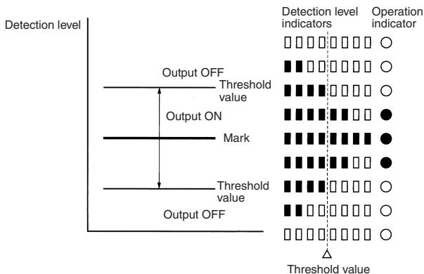
Two-point or Auto-teaching
A single threshold value is set between the mark (registered first) and the base (registered next). The detection level indicators indicate the tolerance between the mark and base.
Remote control Function (Bank Selection, Mark Registration, and Threshold Adjustments)
Under Run Mode or Adjust Mode
The input of any of the signals listed in the following table into the remote control I/O terminal allows remote control of the E3M-V. When the signal is accepted, answer-back output will be turned ON for 0.3 s. Only in the case of one-point teaching, however, can the signal be manually input, provided that the input is ON for 1.5 s or more. Timing Chart
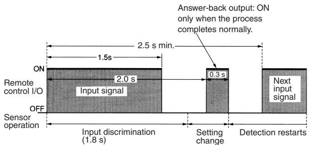
Note: If Signals are sent continuously, make sure that there is an interval of 2.5 s between signal inputs as shown above.
Control Signals
| No. | Control signal | Function |
| 1 | ONOFF0.3s | Bank 1 is selected (operation indicator OFF in TEACH mode) |
| 2 | ONOFF0.6s | Bank 2 is selected (operation indicator ON in TEACH mode) |
| 3 | ONOFF0.9s | Auto-teaching |
| 4 | ONOFF1.2s | Two-point teaching (1st and 2nd) |
| 5 | ONOFF1.5s | One-point teaching (or input for 1.5 s min.) |
| 6 | ONOFF0.3s0.3s | Threshold level 1 is selected. |
| 7 | ONOFF0.3s0.6s0.3s | Threshold level 3 is selected. |
| 8 | ONOFF0.3s0.9s0.3s | Threshold level 5 is selected. |
| 9 | ONOFF0.3s0.3s0.6s | Threshold level 7 is selected. |
| 10 | ONOFF0.3s0.6s0.6s | Threshold level 9 is selected. |
| 11 | ONOFF0.3s0.3s0.9s | Threshold level 11 is selected. |
| 12 | ONOFF0.6s0.3s0.3s | Threshold level 13 is selected. |
Note: The input error of each signal pulse must be within ± 0.1 s
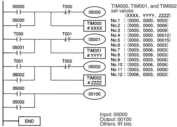
Ladder Program Example
Control signals are input by a ladder program as shown below.
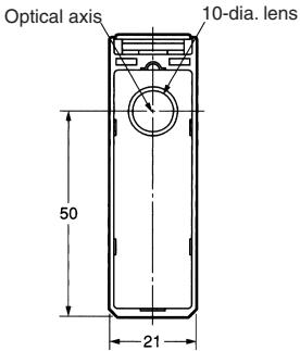
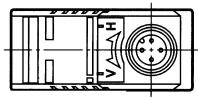
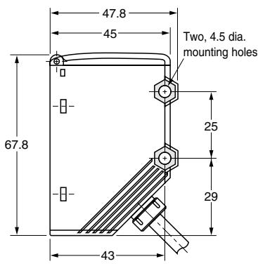
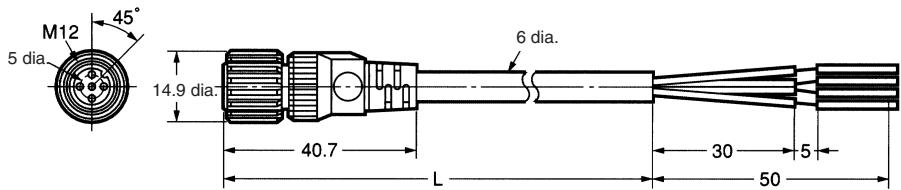
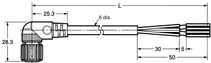
Note: All units are in millimeters unless otherwise indicated.
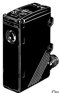
Mark Sensors
Connector Models
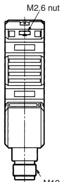
Eight detection level indicators
Seven level threshold indicators
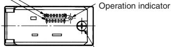
M2.6
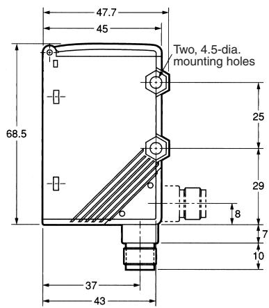
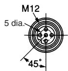
M12 Connector
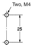
Mounting Holes
Pre-Wired Models
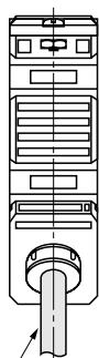
Vinyl-insulated round cable with three
conductors, 6 dia. (17 x 0.16 dia.);
standard length: 2m
Accessories (Order Separately)
Mounting Brackets
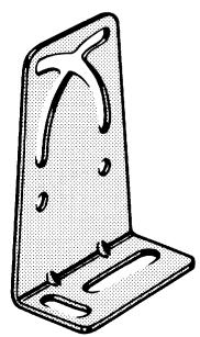
E39-L131
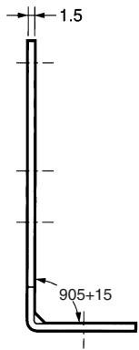
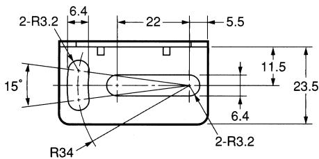
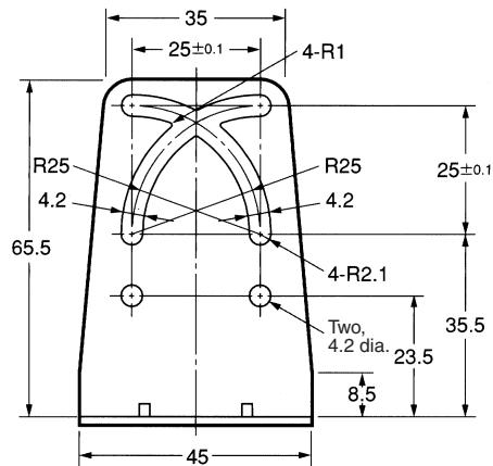
Material: Stainless steel (SUS304)
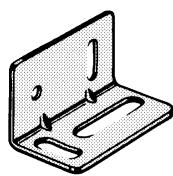
E39-L132
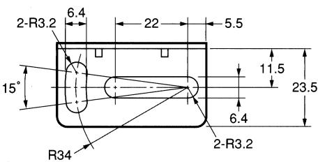
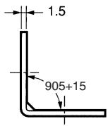
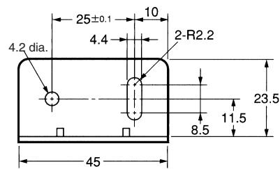
Material: Stainless steel (SUS304)
Sensor I/O Connectors
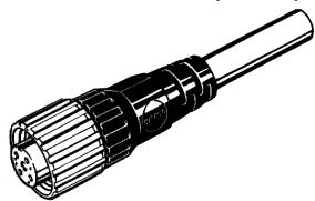
Single-end Connector (Straight Model)
XS2F-D421-D80-A (L=2 m)
XS2F-D421-G80-A (L=5 m)
Single-end Connector (L-shaped Model)
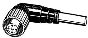
XS2F-D422-D80-A (L=2 m)
XS2F-D422-G80-A (L=5 m)
Installation
Sensor I/O Connector
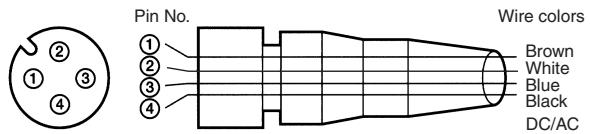
Note: 1. pin No. 2 is not used.
2. For details, refer to the Sensor I/O Connectors Catalog (X065)
| Classification | Wire color | Connector pin No. | Use |
| DC | Brown | 1 | Power supply (+V) |
| --- | 2 | --- | |
| Blue | 3 | Power supply (0V) | |
| Black | 4 | Output |
Precautions
Observe the following precautions to ensure safety.
- Do not use the Sensor in locations subject to flammable or explosive gases.
- Do not use the Sensor in water or conductive solution.
- Do not disassemble, repair, or modify the Sensor.
- Use the Sensor under proper power supply specifications such as the use of AC or DC power supply.
- Do not apply any voltage or current exceeding the rated level.
- Be careful with the power supply polarities and wire correctly.
- Connect the loads correctly.
- Do not short-circuit both ends of loads.
Correct Use
Installation
Power Reset Time
Since the E3M-V is ready to detect objects from 100 ms max. after the E3M-V is turned ON, operate the remaining devices 100 ms after the Sensor is turned ON. If power is supplied to the E3M-V and the load independently, be sure to turn on the E3M-V first.
Power OFF
The E3M-V may output a single pulse when the control power supply is turned OFF. If the E3M-V is connected to a timer or counter to which power is supplied from an independent power supply, the E3M-V will be more likely to output a single pulse when the control power supply is turned OFF. Therefore, supply power to the timer or counter from the same power supply for the E3M-V.
Power Supply Type
No full-wave or half-wave rectified power supplies can be connected to the E3M-V.
Power Supply Connection
Be sure to ground the FG (frame ground) and G (ground) terminals if a switching regulator is connected to the E3M-V, otherwise the E3MV may malfunction due to the switching noise of the switching regulator.
Wiring
Cable
The cable can be extended up to 100m provided that the thickness of the cable is 0.3mm2 minimum.
Repeated Cable Bending
The cable must not be bent repeatedly.
High-tension Lines
The power supply lines of the Sensor must not be wired alongside power lines or high-tension lines in the same conduit, otherwise the Sensor may become damaged or malfunction due to induction noise that may be generated from the power lines or high-tension lines.
Route the lines separately or in a single conduit.
Cable Pulling Force
Do not pull cables with pulling forces exceeding 50N.
Mounting
Screw Tightening
Make sure that the casing is tightened to a maximum torque of 1.2 N o m.
Mounting Direction
When Sensors are mounted to face each other, make sure to adjust the optical axes so that the Sensors will not be mutually interfered.
Others
EEPROM Write Error
An EEPROM error may result if power supply to the Sensor fails or the Sensor is influenced by static noise, in which case the threshold level indicators will flash. Perform the teaching and threshold level setting of the E3M-V again.
M12 Metal Connector
Make sure to connect or disconnect the metal connector after turning off the E3M-V.
Make sure to hold the connector cover when connecting or disconnecting the metal connector.
Tighten the metal connector securely by hand. Do not use any tool, such as pliers, otherwise the metal connector may be damaged.
If the metal connector is not tightened securely, the metal connector may be disconnected by vibration and the proper degree of protection of the E3M-V may not be maintained.
ALL DIMENSIONS SHOWN ARE IN MILLIMETERS.
To convert millimeters into inches, multiply by 0.03937. To convert grams into ounces, multiply by 0.03527.
- Applications
- Dependably Detects Marks on Laminated Sheets
- Auto-Teaching
- Ordering Information
- Technical Guide
- Glossy Sensing Objects
- Operation
- Output Circuits
- Adjustments
- Adjustment Steps
- Mark Registration (Teaching)
- One-point Teaching
- Two-point Teaching
- Precautions when Using Automatic Teaching
- Threshold Level Adjustments
- Detection Level Indicator
- Two-point or Auto-teaching
- Remote control Function (Bank Selection, Mark Registration, and Threshold Adjustments)
- Under Run Mode or Adjust Mode
- Ladder Program Example
- Accessories (Order Separately)
- Sensor I/O Connectors
- Installation
- Sensor I/O Connector
- Precautions
- Correct Use
- Power Reset Time
- Power OFF
- Power Supply Type
- Power Supply Connection
- Wiring
- Cable
- Repeated Cable Bending
- Cable Pulling Force
- Mounting
- Screw Tightening
- Mounting Direction
- Others
- EEPROM Write Error
- M12 Metal Connector
Brand : OMRON
Model : E3M-V
Category : Proximity sensor