
E3S-CL - Proximity sensor OMRON - Free user manual and instructions
Find the device manual for free E3S-CL OMRON in PDF.


| Product Type | Distance-adjustable photoelectric proximity sensor |
| Brand | OMRON |
| Model | E3S-CL1 / E3S-CL2 |
| Category | Industrial proximity sensor |
| Detection range | E3S-CL1: 5 to 200 mm (white paper 200x200 mm); E3S-CL2: 5 to 500 mm |
| Light source | E3S-CL1: Red LED (700 nm); E3S-CL2: Infrared LED (860 nm) |
| Supply voltage | 10 to 30 VDC (including 10% ripple) |
| Power consumption | E3S-CL1: 35 mA max; E3S-CL2: 50 mA max |
| Output type | Selectable NPN/PNP open collector, selectable Light-ON/Dark-ON |
| Response time | E3S-CL1: 1 ms max; E3S-CL2: 2 ms max |
| Hysteresis | E3S-CL1: 2% max; E3S-CL2: 10% max of detection distance |
| Black/white error | E3S-CL1: 2% max; E3S-CL2: 10% max |
| Protection degree | IP67 (IEC), NEMA 6P (indoor) |
| Operating temperature | -25°C to 55°C (no freezing or condensation) |
| Operating humidity | 35% to 85% RH (no condensation) |
| Housing material | Die-cast zinc (zamak) |
| Lens material | Acrylic |
| Weight (packed) | Approx. 170 g |
| Cable length | 2 m (pre-wired) |
| Supplied accessories | Mounting bracket, M4x12 screws, adjustment screwdriver, instruction manual |
| Special functions | 6-turn distance adjustment with indicator, NPN/PNP selection, Light-ON/Dark-ON, reverse polarity protection, short-circuit protection, mutual interference prevention |
| Compliance | CE (IEC947-5-2, EN50081-2, EN55011) |
Frequently Asked Questions - E3S-CL OMRON
User questions about E3S-CL OMRON
0 question about this device. Answer the ones you know or ask your own.
Ask a new question about this device
Download the instructions for your Proximity sensor in PDF format for free! Find your manual E3S-CL - OMRON and take your electronic device back in hand. On this page are published all the documents necessary for the use of your device. E3S-CL by OMRON.
USER MANUAL E3S-CL OMRON
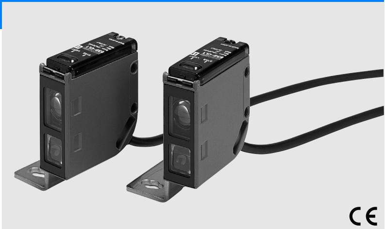
Distance setting photoelectric sensor in metal housing
E3S-CL
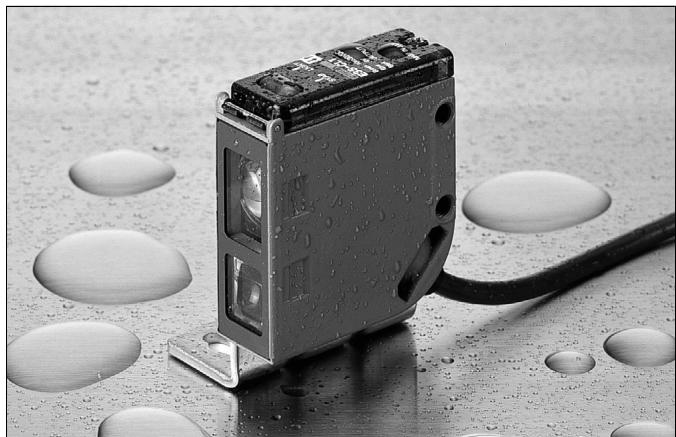
- High water, oil and detergent resistance
- Minimal black/white error for highest reliability detecting different colored objects (E3S-CL1)
Features
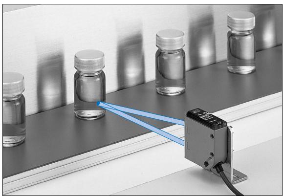
Eliminates Background Influences with a Hysteresis of Only 2% max. (E3S-CL1)
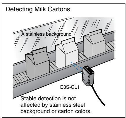
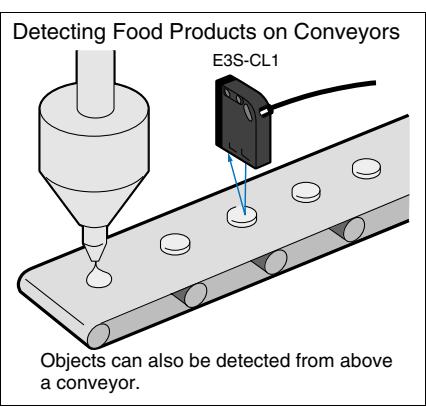
The hysteresis is the industry's minimum 2% max. (E3S-CL1). As a triangulation measuring is used, objects behind the setting distance cannot be detected. The sensor is insensitive to the influence of background objects of high reflectivity, and stable detects works on a conveyor from above. The hysteresis of the E3S-CL2 is 10% max. of the detecting distance ( 5% max. for white paper).
What Is Distance Setting?
(Differences from other detecting system)
Distance-setting
| Fea-tures | When the sensing object moves in direction A, the center position of the reflected light moves in direction B. This is received by the 2-split photodiode and the place where the incident levels are the same on the N and F sides is defined as the setting distance. The object is detected by the incident circuit processing only when N F, and is not detected when N F. Therefore, detection is stable without being influenced by the work type and background objects. |
| Struc-ture | Received element (Two division photodiode) N: Near F: Far A setting distance variable Light source LED Setting range ← Detecting range → A |
Diffuse-reflective
| Fea-tures | Since the level of the reflected light is judged for detection, the sensing distance varies with the color, material and/or size of the work. A malfunction may occur if there is any object of high reflectivity in the background. |
| Struc-ture | Received element Light source LED Detecting area ←→ Detecting range |
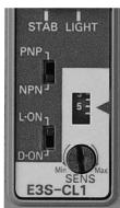
6-turn adjuster with indicator
- The 6-turn adjuster with indicator ensures ease of distance setting.
- Fine distance setting is possible.
Optical Technology of E3S-CL
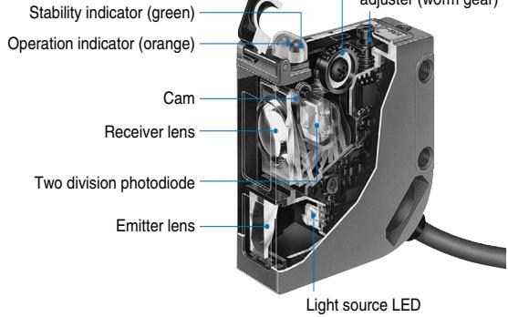
By turning the distance setting adjuster (worm gear), the rotation of the gear moves the cam to change the incident angle of the whole incident block (lens and photodiode), setting the distance.
- NPN/PNP Output Selectable.
Light-ON/Dark-ON is also switch selectable.
Conforms to Applicable EN/IEC Standards
- The sensors satisfy the electrical safety (IEC947-5-2), noise resistance (IEC947-5-2, IEC801-2/3/4) and noise radiation restrictions (EN500 81-2, EN55011) required for photoelectric sensors.
Application
E3S-CL1
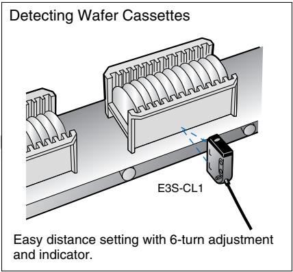
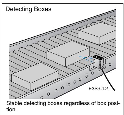
E3S-CL2
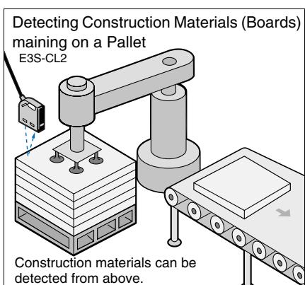
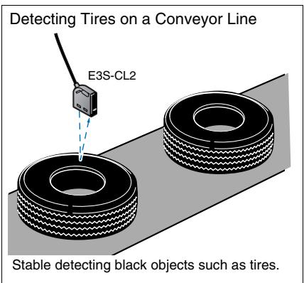
Red light Infrared light
| Shape | Sensing/Setting range | Model |
| 5 Min. setting 40mm Setting range 40 to 200 mm Max. setting 5 to 200 mm | E3S-CL1 | |
| 5 Min. setting 50mm Setting range 50 to 500 mm Max. setting 5 to 500 mm | E3S-CL2 |
Rating/performance
| Sensing method Item | Model | Distance-setting | |
| E3S-CL1 | E3S-CL2 | ||
| Sensing | 5 to 200 mm (White paper 200 x 200 mm) (Setting distance 200 mm) | 5 to 500 mm (White paper 200 x 200 mm) (Setting distance 500 mm) | |
| Setting range | 40 to 200 mm (White paper 200 x 200 mm) | 50 to 500 mm (White paper 200 x 200 mm) | |
| Differential distance | 2% max. | 10% max. | |
| Reflectivity characteristics (black/white error) | *1 | 2% max. | 10% max. |
| Light source (wave length) | Red LED (700 nm) | Infrared LED (860 nm) | |
| Power supply voltage | 10 to 30 VDC [ripple (p-p) 10% included] | ||
| Current consumption | 35 mA max. | 50 mA max. | |
| Control output | Load supply voltage 30 VDC max., load current 100 mA max. (residual voltage NPN output: 1.2 V max., PNP output: 2.0 V max.) Open collector output type (NPN/PNP switch selectable) Light-ON/Dark-ON switch selectable | ||
| Protective circuits | Reverse polarity protection, output short-circuit protection, mutual interference prevention | ||
| Response time | Operation or reset: 1 ms max. | Operation or reset: 2 ms max. | |
| Distance setting | 6-turn endless adjuster (with indicator) | ||
| Ambient illuminance | Incandescent lamp: 5,000 lux max. Sunlight 10,000 lux max. | ||
| Ambient temperature | Operating/Storage: -25°C to 55°C (with no icing or condensation) | ||
| Ambient humidity | Operating/Storage: 35% to 85%RH (with no condensation) | ||
| Insulation resistance | 20 M min. at 500 VDC | ||
| Dielectric strength | 1,000 VAC at 50/60 Hz for 1 minute | ||
| Vibration resistance | 10 to 55 Hz, 1.5 mm double amplitude for 2 hours each in X, Y, and Z directions | ||
| Shock resistance | Destruction: 500 m/s² for 3 times each in X, Y, and Z directions | ||
| Protective structure | IEC Standard IP67, NEMA 6P (limited to indoor use)*2 | IEC Standard IP67, NEMA 6P (limited to indoor use) | |
| Connection method | Pre-wired models (standard length: 2 m) | ||
| Weight (Packed state) | Approx. 170 g | ||
| Ma-terial | Case | Zinc diecast | |
| Operation panel cover | Polyethyl sulfon | ||
| Lens | Acrylics | ||
| Mounting Brackets | Stainless steel (SUS304) | ||
| Accessories | Mounting bracket, hexagon bolt M4 x 12 (with spring washer, flat washer), adjusting screwdriver, instruction manual | ||
1. Sensing distance difference between standard white paper (reflectivity 90%) and standard black paper (reflectivity 5%)
2. NEMA (National Electrical Manufacturers Association) Standards
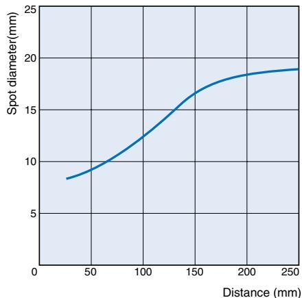
Spot Diameter vs. Sensing Distance
E3S-CL1
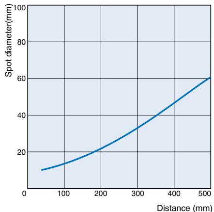
E3S-CL2
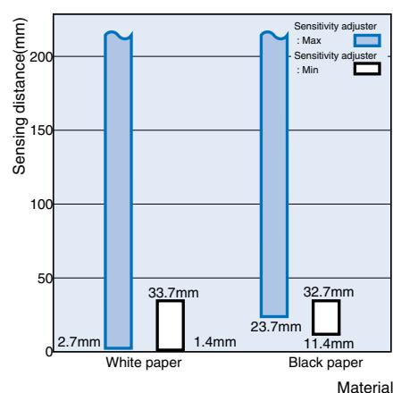
Short distance characteristic
E3S-CL1
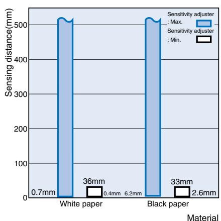
E3S-CL2
Output Circuit Diagram
NPN output
| Model | Operating status of output transistor | Timing chart | Mode selec-tion switch | Output circuit |
| E3S-CL1 E3S-CL2 | Light ON | Incident Interrupted Operation indicator (orange) ON OFF Output transistor Load Operate (Relay) Reset | L ON (LIGHT ON) | Brown 10 to 30 VDC Load Load current Black Control output NPN and PNP output selector NPN output transistor ZD Blue 0V * Please make a changeover switch into the NPN side. |
| Dark ON | Incident Interrupted Operation indicator (orange) ON OFF Output transistor Load Operate (Relay) Reset | D ON (DARK ON) |
PNP output
| Model | Operating status of output transistor | Timing chart | Mode selec-tion switch | Output circuit |
| E3S-CL1 E3S-CL2 | Light ON | Incident Interrupted Operation indicator (orange) OFF Output transistor Load Operate (Relay) Reset | L ON (LIGHT ON) | Brown 10 to 30 VDC Operation indicator Stability indicator Main circuit NPN and PNP output transistor ZD Black Load current Load Control output Blue 0V * Please make a changeover switch into the PNP side. |
| Dark ON | Incident Interrupted Operation indicator (orange) OFF Output transistor Load Operate (Relay) Reset | D ON (DARK ON) |
Nomenclature:
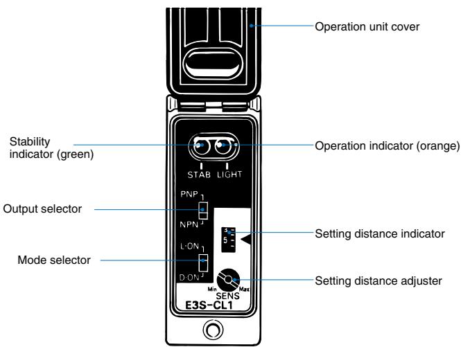
Operation panel
Output selection switch
① When using the sensor with NPN output, move the switch to the NPN position.
② When using the sensor with PNP output, move the switch to the PNP position.
Mode selection switch
① When using the sensor with Light-ON, move the switch to the L-ON position.
② When using the sensor with Dark-ON, move the switch to the D-ON position.
Distance Adjuster
① Turning the distance setting adjuster clockwise (to the Max position) increases the detecting distance, and turning it counterclockwise (to the Min position) decreases the distance.
(2) The distance setting adjuster is a 6-turn endless adjuster ranging from the Min position to the Max position, and its number of turns is displayed on the setting distance indicator according to the rotation of the adjuster.
Sensitivity adjustment (distance setting type, Light-ON)
| Sequence | Detection state | Position of dis-tance setting ad-juster | State of setting dis-tance indicator | Indicator state | Adjustment Steps |
| (1) Point (A) | Photoelectric SensorSensing object | (A)Min Max | (A)134 | ON→OFFOFF→ONStability indicator (green)Operation indicator (orange) | Place a sensing object in the predetermined position, turn the adjuster clockwise until the incident indicator (orange) is turned ON, and define this position as (A). |
| (2) Points (B),(C) | Photoelectric SensorSensing object | (B)CMax | (C)354 | ON→OFFON→OFFStability indicator (green)Operation indicator (orange) | (1) If there is a background object, remove the sensing object, turn the adjuster further clockwise until the incident indicator (orange) is turned ON, and define this position as (B). Turn the adjuster counterclock-wise from (B) until the incident indicator (orange) is turned OFF, and define this position as (C). (2) If there is no background object, define the maximum adjuster position (Max) as (C). |
| (3) Setting | --- | (A)Min CMax | (A)134(C)54 | ONON←OFFStability indicator (green)Operation indicator (orange) | Set the adjuster in the middle of positions (A) and (C). Also make sure that the stability indicator (green) is turned ON when there is an object and when there is no object. When the indicator is not turned ON, reexamine the detection method since there is a little allowance. |
Precautions
Correct Use
Design
Cable
The oil-resistant cable is used to ensure oil resistance.
(E3S-CL2)
Installation
Sensor installation
Mounting orientation
- Install the photoelectric sensor in such manner that its detection surface and the object surface are parallel (without inclination relative to the sensing object).

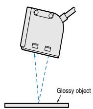
If the sensing object has a glossy surface, incline the Sensor by 5^ to 10^ as shown on the right. In this case, ensure that the Sensor is not influenced by any background objects.
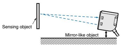
- If there is a mirror-smooth object under the photoelectric sensor, operation may become instable. Therefore, incline the photoelectric sensor as shown below or move it away from the object.
- Install the photoelectric sensor in either of the following orientations, being careful of the direction in which the sensing object will move.
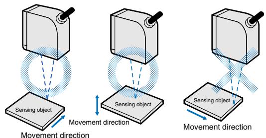
- Also, when the color/material of the sensing object varies extremely, install the photoelectric sensor in either of the following orientations.
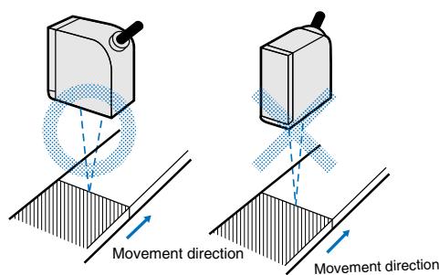
- Install the photoelectric sensor so that the sun, fluorescent lamp, incandescent lamp or any other strong light will not enter the directional angle range of the sensor.
Mounting Precautions
- Do not strike the Photoelectric Sensor with a hammer or any other tool during the installation of the Sensor, or the Sensor will loose its water-resistive properties.
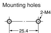
- Use M4 screws.
- Tighten the screws to the torque of 1.2 Nm max.
Others
Oil resistance/chemical resistance (E3S-CL2)
For the oil resistance of E3S-CL2, the Sensor has passed tests on the oils given in the following table. Refer to the table for examining the oil to be used. Depending on the oil type, however, the Sensor may not be able to exhibit its performance.
| Testing oil classificatio | JIS classificatio | Product name | Dynamic vis-cosity (mm2/s) at 40°C | PH |
| Lubricant | --- | Velocity No. 3 | 2.02 | --- |
| Water-in-solublecoolant | Class 2No. 5 | Daphne Cut | Not less than10 to less than50 | |
| Class 2No. 11 | Yushiron Oil No. 2ac | Less than 10 | ||
| Water-solublecoolant | Class W1No. 1 | Yushiroken EC50T-3 | --- | 7'9.5 |
| Yushiron Lubic HWC68 | 7'9.9 | |||
| Class W1No. 2 | Gryton 1700D | 7'9.2 | ||
| Class W2No. 1 | Yushiroken S50N | 7'9.8 |
Note: 1. E3S-C was submerged in the oils in the above table at 50^ for 240
hours, and passed the test of 100-M or more insulation resistance.
2. For use in the environment where E3S-C is exposed to the oil other than those in the above table, use the dynamic viscosity and PH in the above table. Pre-check the oils since the sensor may be affected by additives etc. in the oils.
Dimensions (Unit: mm)
E3S-CL1
E3S-CL2
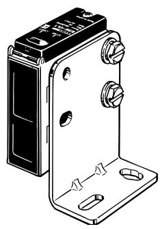
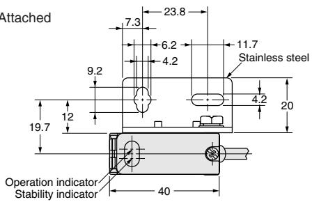
With Mounting Bracket Attached
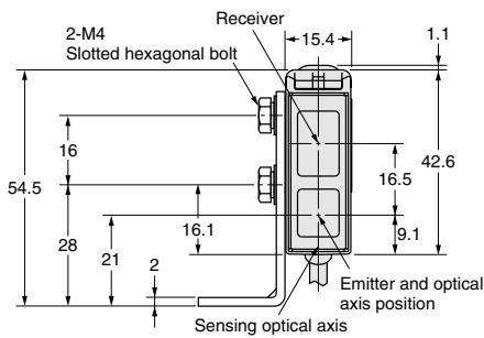
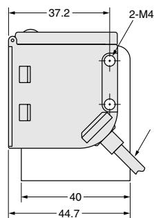
E3S-CL1: Vinyl-insulated round cable of 4 dia. 3 cores conductor cross-sectional area: 0.2mm^2 insulation diameter: 1.1mm Standard length: 2m
E3S-CL2: Vinyl-insulated round cable of 4 dia.
3 cores conductor cross-sectional area: 0.2mm^2 ; insulation diameter: 1.1mm Standard length: 2m
Note: The output selector, mode selector and distance setting adjuster are exposed when the cover is opened.
ALL DIMENSIONS SHOWN ARE IN MILLIMETERS.
To convert millimeters into inches, multiply by 0.03937. To convert grams into ounces, multiply by 0.03527.
Cat. No. E237-E2-02A-X
In the interest of product improvement, specifications are subject to change without notice.
- Distance setting photoelectric sensor in metal housing
- E3S-CL
- Features
- Eliminates Background Influences with a Hysteresis of Only 2\% max. (E3S-CL1)
- What Is Distance Setting?
- (Differences from other detecting system)
- 6-turn adjuster with indicator
- Optical Technology of E3S-CL
- Conforms to Applicable EN/IEC Standards
- Application
- Output Circuit Diagram
- Nomenclature:
- Output selection switch
- Mode selection switch
- Distance Adjuster
- Precautions
- Correct Use
- Mounting Precautions
- Others
- Oil resistance/chemical resistance (E3S-CL2)
- Dimensions (Unit: mm)
Brand : OMRON
Model : E3S-CL
Category : Proximity sensor