
E3ZM-V - Proximity Sensors OMRON - Free user manual and instructions
Find the device manual for free E3ZM-V OMRON in PDF.


| Product Type | Photoelectric sensor for print mark detection |
| Brand | OMRON |
| Model | E3ZM-V |
| Category | Proximity sensor |
| Detection Method | Diffuse reflection (mark detection) |
| Detection Distance | 12 ± 2 mm |
| Spot Diameter | 2 mm max. |
| Light Source | White LED (450-700 nm) |
| Power Supply | 10-30 VDC, power consumption 600 mW max. |
| Response Time | 50 µs max. |
| Protection Rating | IP67 / IP69K (with connector) |
| Housing Material | SUS316L (stainless steel) |
| Lens Material | PMMA (polymethyl methacrylate) |
| Weight (cable model) | Approx. 85 g |
| Weight (connector model) | Approx. 35 g |
| Operating Temperature | -40 to 60°C |
| Operating Humidity | 35% to 85% non-condensing |
| Teaching Methods | 2-point teaching (manual) and automatic teaching (remote) |
| Chemical Resistance | Resistant to common detergents and disinfectants |
| Output Type | NPN or PNP (depending on model) |
| Connection | 2 m pre-wired cable or M8 4-pin connector |
| Built-in Protections | Polarity reversal, load short-circuit, output polarity protection |
| Maintenance and Cleaning | Clean with a soft cloth; do not use organic solvents; resistant to detergents but avoid high-pressure jets |
| Safety | Do not use for personal safety applications; respect rated voltages |
| Included Accessories | Instruction manual |
Frequently Asked Questions - E3ZM-V OMRON
User questions about E3ZM-V OMRON
0 question about this device. Answer the ones you know or ask your own.
Ask a new question about this device
Download the instructions for your Proximity Sensors in PDF format for free! Find your manual E3ZM-V - OMRON and take your electronic device back in hand. On this page are published all the documents necessary for the use of your device. E3ZM-V by OMRON.
USER MANUAL E3ZM-V OMRON
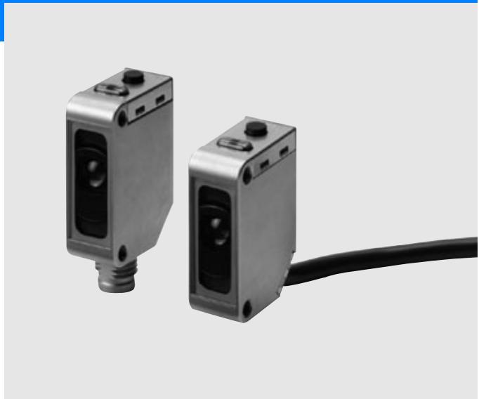
Print mark detection photoelectric sensor in compact stainless steel housing
E3ZM-V
The detergent resistant photoelectric sensor in a robust stainless steel housing provides reliable detection of all common print marks in packaging applications.
- White LED for stable detection of differently colored print marks
SUS 316L stainless steel housing - Easy-to-use teach-in button or remote dynamic teach
- Fast response time of 50 s
Features
Reliable print mark detection within OMRON's most popular E3Z sensor family
The E3ZM-V provides reliable print mark detection in the compact sized E3Z housing. For packaging machine makers the E3Z family offers a complete sensor platform with one mounting concept simplifying installation and machine design.
- Space-saving design with an SUS316L housing
The compact design reduces volume by 90% compared to conventional mark sensors.

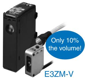
Conventional mark sensor size
Coaxial optical system
The coaxial optical system ensures stable detection of print marks on uneven surfaces.
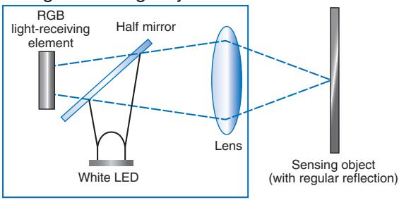
Straight Sensing Object
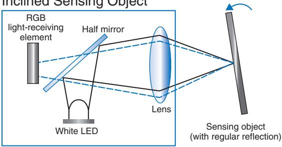
Inclined Sensing Object
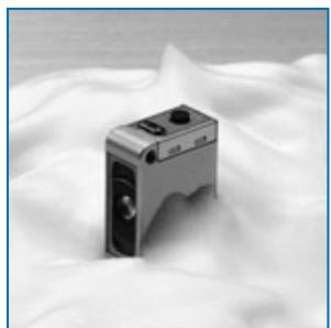
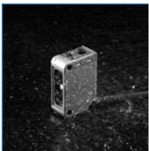
Water and detergent resistance
The housing is constructed of corrosion-resistant SUS316L, and the display cover is PES (polyethersulfone).
Both materials are highly resistant to the corrosive effects of detergents and disinfectants.
The IP69k tight housing construction ensures long sensor lifetime in often cleaned environments.
Same Durability as the E3ZM
Reliable detection of differently colored print marks due to RGB signal processing
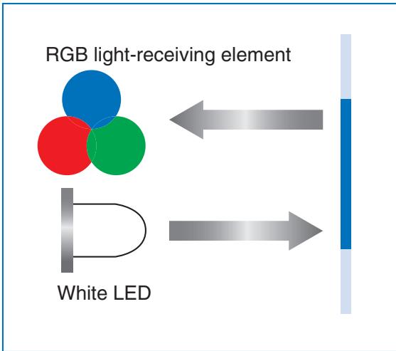
- RGB signal processing
The white LED and RGB signal processing ensure the stable detection of differently colored print marks.
The processing algorithm provides a fast response time of 50~ s
Patent pending
- Easy setting with 2-point or automatic teaching
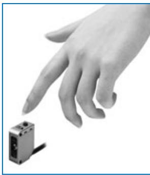
2-point Teaching (Manual)
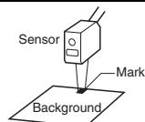
Simply aim the beam spot at the mark portion and background portion, and press the teaching button.
Automatic Teaching (Remote)
Send a pulse to the remote control input and have the mark pass by six times for automatic teaching.
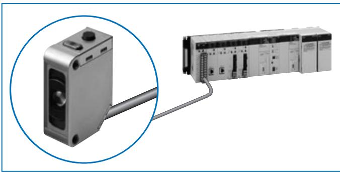
Ordering Information
White light
Sensor
| Sensing method | Appearance | Connection method | Sensing distance | Model | ||||
| NPN output | PNP output | |||||||
| Mark Sensor (Diffuse reflective) | ←→ | Pre-wired (2 m) | 12±2 mm | *1 | E3ZM-V61 2M | E3ZM-V81 2M | ||
| Connector (M8, 4 pins) | E3ZM-V66 | E3ZM-V86 | ||||||
*1. A deviation of ±2 mm (typical value) can be handled for combinations of white, yellow, and black. Refer to page 5 for the detection capability for other color combinations.
Accessories
Sensor I/O Connectors
| Size | Cable | Appearance | Cable type | Model | |
| M8 (4 pins) | Standard | Straight | 2 m | 4-wire | XS3F-E421-402-A |
| 5 m | XS3F-E421-405-A | ||||
| L-shaped | 2 m | XS3F-E422-402-A | |||
| 5 m | XS3F-E422-405-A | ||||
Note 1: The outer cover of the cable is made of PVC (polyvinyl chloride), the nut is SUS316L, and the degree of protection is IP67. When high-pressure washing will be used, select an I/O Connector that has IP69K degree of protection.
Note 2: For detergent resistant cable connectors with stainless steel nuts see accessory datasheet E26E or contact your OMRON representative
Mounting Brackets
| Appearance | Model (Material) | Quantity | Remarks |
| E39-L153 (SUS304) | 1 | Mounting Brackets | |
| E39-L104 (SUS304) | 1 | ||
| E39-L43 (SUS304) | 1 | Horizontal Mounting Bracket *1 | |
| E39-L142 (SUS304) | 1 | Horizontal Protective Cover Bracket *1 | |
| E39-L44 (SUS304) | 1 | Rear Mounting Bracket |
*1. Cannot be used for Standard Connector models.
| Appearance | Model (Metal material) | Quantity | Remarks |
| E39-L98 (SUS304) | 1 | Protective Cover Bracket *1 | |
| E39-L150 (SUS304) | 1 set | (Sensor adjuster) Easily mounted to the aluminum frame rails of conveyors and easily adjusted. For vertical angle adjustment | |
| E39-L151 (SUS304) | 1 set | ||
| E39-L144 (SUS304) | 1 set | Compact Protective Cover Bracket *1 |
Ratings and Specifications
| Sensing method | Diffuse reflective (mark detection) | |
| Model Item | NPN output | E3ZM-V61/-V66 |
| PNP output | E3ZM-V81/-V86 | |
| Sensing distance | 12±2 mm *1 | |
| Sensing range | Depends on the combination of colors. Refer to Engineering Data on page 5 for details. | |
| Spot diameter | 2-mm dia. max. | |
| Light source (wavelength) | White LED (450 to 700 nm) | |
| Power supply voltage | 10 to 30 VDC, including 10% ripple (p-p) | |
| Power consumption | 600 mW max. (current consumption for a 30-V power supply voltage: 20 mA max.) | |
| Control output | Load power supply voltage: 30 VDC max., Load current: 100 mA max. (Residual voltage: 2 V max.) Open-collector output (NPN/PNP output depending on model) | |
| Remote control input | NPN output ON: Short-circuit to 0 V, or 1.5 V max. (source current: 1 mA max.) NPN output OFF:Open or Vcc 1.5 V to Vcc (leakage current: 0.1 mA max.) PNP output ON: Vcc 1.5 V to Vcc (sink current: 1 mA max.) PNP output OFF: Open or 1.5 V max. (leakage current: 0.1 mA max.) | |
| Operating modes | Set in the order of the teaching operation. *2 | |
| Protection circuits | Reversed power supply polarity, Load short-circuit protection, and Reversed output polarity protection | |
| Response time | Operate or reset: 50 μs max. | |
| Sensitivity adjustment | Teaching method | |
| Ambient illumination | (Receiver side) Incandescent lamp: 3,000 lx max., Sunlight: 10,000 lx max. | |
| Ambient temperature range | Operating: -40 to 60°C *3, Storage: -40 to 70°C (with no icing or condensation) | |
| Ambient humidity range | Operating: 35% to 85%, Storage: 35% to 95% (with no condensation) | |
| Insulation resistance | 20 M min. (at 500 VDC) | |
| Dielectric strength | 1,000 VAC at 50/60 Hz for 1 min | |
| Vibration resistance (destruction) | 10 to 55 Hz, 1.5-mm double amplitude for 2 h each in X, Y, and Z directions | |
| Shock resistance (destruction) | 500 m/s² for 3 times each in X, Y, and Z directions | |
| Degree of protection | IEC 60529: IP67, DIN 40050-9: IP69K *4 | |
| Connection method | Pre-wired cable (standard length: 2 m) or M8 4-pin connector | |
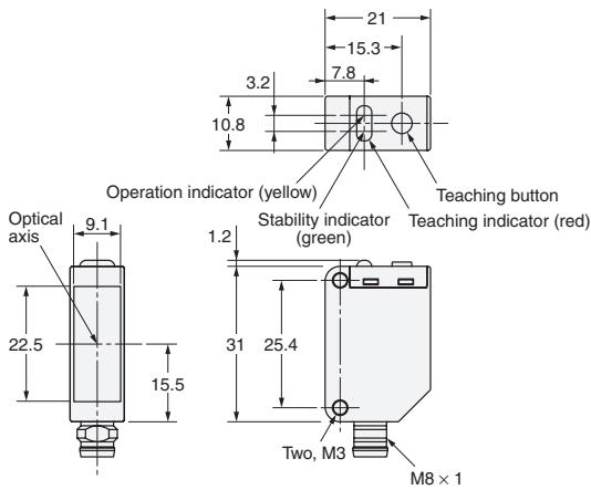
| Indicator | Operating indicator (yellow), Stability indicator (green), and Teaching indicator (red) | |
| Weight (packed state) | Pre-wired models (2-m cable): Approx. 85 g Connector models: Approx. 35 g | |
| Materials | Housing | SUS316L |
| Lens | PMMA (polymethylmethacrylate) | |
| Indication | PES (polyethersulfone) | |
| Buttons | Fluoro rubber | |
| Cable | PVC (polyvinyl chloride) | |
| Accessories | Instruction sheet | |
*1. A deviation of ± 2mm (typical value) can be handled for combinations of white, yellow, and black. Refer to page 5 for the detection capabilities for other colors.
2. Mark Sensor output switching: When teaching, specify the ON color first and the OFF color second.
3. Do not bend the cable in temperatures of -25°C or lower.
*4. For connector models IP69k rating is with connector attached.
Standard Sensing Object for the Mark Sensor
| Color | Munsell color notation |
| White | N9.5 |
| Red | 4R 4.5/12.0 |
| Yellow-red | 4YR 6.0/11.5 |
| Yellow | 5Y 8.5/11.0 |
| Yellow-green | 3GY 6.5/10.0 |
| Green | 3G 6.5/9.0 |
| Blue-green | 5BG 4.5/10.0 |
| Blue | 3PB 5.0/10.0 |
| (Black) | (N2.0) |
Color vs. Detection Capability
E3ZM-V□□
Teaching Capabilities
Note: The above chart shows the combinations of colors for which teaching is possible at a sensing distance of 12 mm .
Detectable Ranges
E3ZM-V□□
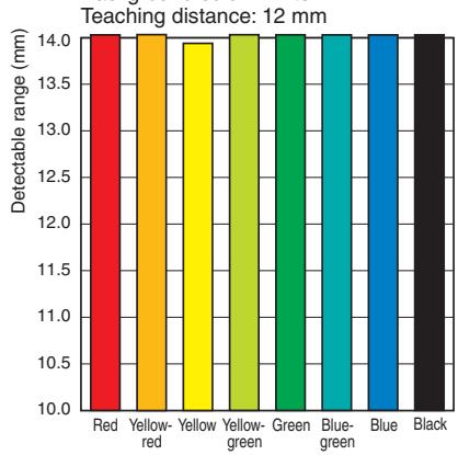
Background color: White
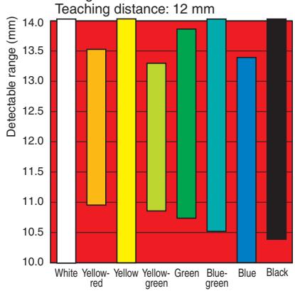
Background color: Red
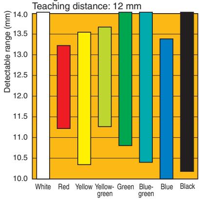
Background color: Yellow-red
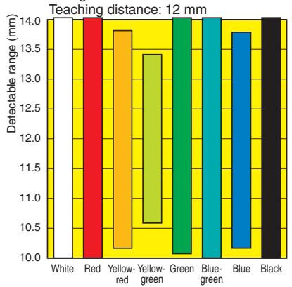
Background color: Yellow

Background color: Yellow-green
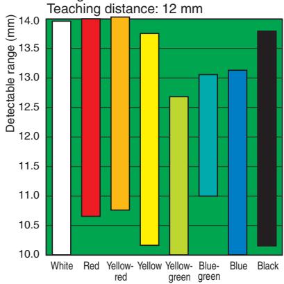
Background color: Green
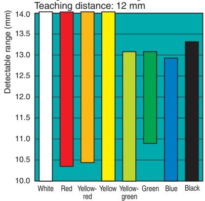
Background color: Blue-green
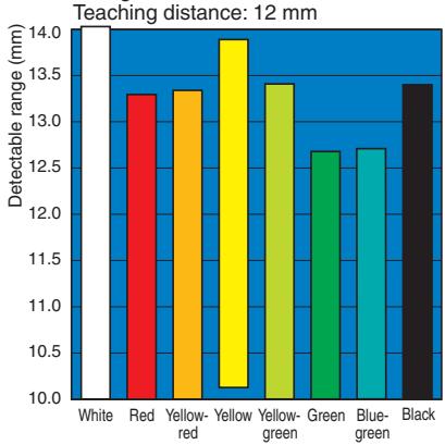
Background color: Blue
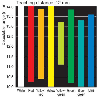
Background color: Black
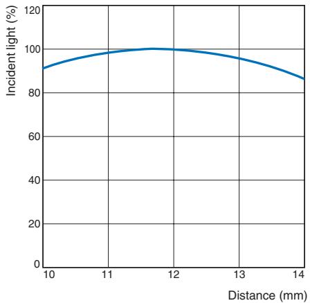
Excess Gain vs. Distance E3ZM-V□□
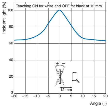
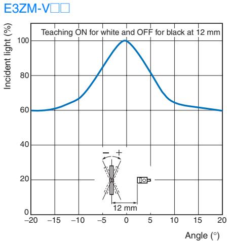
Angle vs. Incident Characteristics E3ZM-V□
I/O Circuit Diagrams
NPN Output
| Model | Timing charts | Output circuit | |||||
| E3ZM-V61 | Sensing object | Color taught 1st | Color taught 2nd | Color taught 1st | Color taught 2nd | Operation indicator (yellow) | Stability indicator (green) |
| E3ZM-V66 | Operation indicator (yellow) | ON OFF | Teaching indicator (red) | Photo- electric Sensor Main Circuit | |||
| Output transistor | ON OFF | Main Circuit | Remote control input Black | ||||
| Load (e.g., relay) | Operate Reset | Between brown (1) and black (4) leads | Control output Blue | ||||
| M8 Connector Pin Arrangement | |||||||
| ②④③ | |||||||
PNP Output
| Model | Timing charts | Output circuit | |||||
| E3ZM-V81 | Sensing object | Color taught 1st | Color taught 2nd | Color taught 1st | Color taught 2nd | Operation indicator (yellow) | Stability indicator (green) |
| E3ZM-V86 | Operation indicator (yellow) | ON OFF | Teaching indicator (red) | Black control output | |||
| Output transistor | ON OFF | Photo- electric Sensor Main Circuit | Remote Pink control input Load | ||||
| Load (e.g., relay) | Operate Reset | Between blue (3) and black (4) leads | Blue | M8 Connector Pin Arrangement | |||
Plugs (Sensor I/O Connectors)
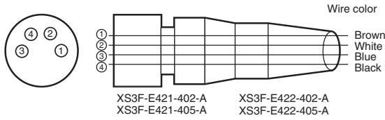
M8 4-pin Connectors
| Classification | Wire color | Connector pin No. | Application |
| DC | Brown | 1 | Power supply (+v) |
| White | 2 | Remote control input | |
| Blue | 3 | Power supply (0 V) | |
| Black | 4 | Output |
Note: The above M8 Connectors made by OMRON are IP67. Do not use them in an environment where IP69K is required.
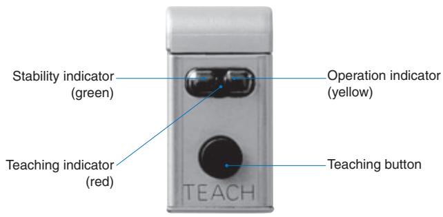
Teaching Models
Safety Precautions
Refer to Warranty and Limitations of Liability on page 12.

WARNING
This product is not designed or rated for directly or indirectly ensuring safety of persons. Do not use it for such a purpose.


CAUTION
Do not use the product with voltage in excess of the rated voltage. Excess voltage may result in malfunction or fire.
Never use the product with an AC power supply. Otherwise, explosion may result.
When cleaning the product, do not apply a high-pressure spray of water to one part of the product. Otherwise, parts may become damaged and the degree of protection may be degraded.


Precautions for Safe Use
The following precautions must be observed to ensure safe operation of the Sensor.
Operating Environment
Do not use the Sensor in an environment where explosive or flammable gas is present.
Connecting Connectors
Be sure to hold the connector cover when inserting or removing the connector.
When using an XS3F Connector, be sure to tighten the connector lock by hand; do not use pliers or other tools.
If the tightening is insufficient, the degree of protection will not be maintained and the Sensor may become loose due to vibration. The appropriate tightening torque is 0.3 to 0.4N· m . When using another, commercially available connector, follow the usage and tightening torque instructions provided by the manufacturer.
Load
Do not use a load that exceeds the rated load.
Low-temperature Environments
Do not touch the metal surface with your bare hands when the temperature is low. Touching the surface may result in a cold burn.
Oily Environments
Do not use the Sensor in oily environments. They may damage parts and reduce the degree of protection.
Modifications
Do not attempt to disassemble, repair, or modify the Sensor.
Outdoor Use
Do not use the Sensor in locations subject to direct sunlight.
Cleaning
Do not use thinner, alcohol, or other organic solvents.
Otherwise, the optical properties and degree of protection may be degraded.
Cleaning
Do not use highly concentrated cleaning agents. Otherwise, malfunction may result. Also, do not use high-pressure water with a level of pressure that exceeds the stipulated level. Otherwise, the degree of protection may be reduced.
Surface Temperature
Burn injury may occur. The Sensor surface temperature rises depending on application conditions, such as the ambient temperature and the power supply voltage. Use caution when operating or performing maintenance on the Sensor.
Cable Bending
Do not bend the cable in temperatures of -25^ or below. Otherwise, the cable may be damaged.
Precautions for Correct Use
Do not use the Sensor in any atmosphere or environment that exceeds the ratings.
Do not install the Sensor in the following locations.
(1)Locations subject to direct sunlight
(2)Locations subject to condensation due to high humidity
(3)Locations subject to corrosive gas
(4)Locations where the Sensor may receive direct vibration or shock
Connecting and Mounting
(1) The maximum power supply voltage is 30 VDC. Before turning the power ON, make sure that the power supply voltage does not exceed the maximum voltage.
(2)Laying Sensor wiring in the same conduit or duct as high-voltage wires or power lines may result in malfunction or damage due to induction. As a general rule, wire the Sensor in a separate conduit or use shielded cable.
(3) Use an extension cable with a minimum thickness of 0.3 ~mm^2 and less than 50 ~m long.
(4)Do not pull on the cable with excessive force.
(5)Pounding the Photoelectric Sensor with a hammer or other tool during mounting will impair water resistance. Also, use M3 screws.
(6)Mount the Sensor either using the bracket (sold separately) or on a flat surface.
(7)Be sure to turn OFF the power supply before inserting or removing the connector.
Power Supply
If a commercial switching regulator is used, ground the FG (frame ground) terminal.
Power Supply Reset Time
The Sensor will be able to detect objects 100 ms after the power supply is tuned ON. Start using the Sensor 100 ms or more after turning ON the power supply. If the load and the Sensor are connected to separate power supplies, be sure to turn ON the Sensor first.
Turning OFF the Power Supply
Output pulses may be generated even when the power supply is OFF.
Therefore, it is recommended to first turn OFF the power supply for the load or the load line.
Load Short-circuit Protection
This Sensor is equipped with load short-circuit protection, but be sure to not short circuit the load. Be sure to not use an output current flow that exceeds the rated current. If a load short circuit occurs, the output will turn OFF, so check the wiring before turning ON the power supply again. The short-circuit protection circuit will be reset. The load shortcircuit protection will operate when the current flow reaches 1.8 times the rated load current. When using a capacitive load, use an inrush current of 1.8 times the rated load current or lower.
Water Resistance
Do not use the Sensor in water, rainfall, or outdoors.
When disposing of the Sensor, treat it as industrial waste.
Mounting Diagram
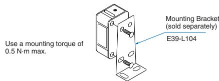
Resistance to Detergents, Disinfectants, and Chemicals
- The Sensor will maintain sufficient performance in typical detergents and disinfectants, but performance may suffer in some types of detergents, disinfectants, and chemicals. Refer to the following table prior to use.
- The E3ZM has passed detergent and disinfectant resistance testing for the substances listed in the following table. Use this table as a guide when considering detergents and disinfectants.
| Type | Product name | Concen-tration | Tempera-ture | Time |
| Chemicals | Sodium hydroxide, NaOH | 1.5% | 70°C | 240 h |
| Potassium hydroxide, KOH | 1.5% | 70°C | 240 h | |
| Phosphoric acid, H3PO4 | 2.5% | 70°C | 240 h | |
| Sodium hypochlorite, NaClO | 0.3% | 25°C | 240 h | |
| Hydrogen peroxide, H2O2 | 6.5% | 25°C | 240 h | |
| Alkaline foaming cleansers | Topax 66s (Ecolab) | 3.0% | 70°C | 240 h |
| Acidic foaming cleansers | Topax 56 (Ecolab) | 5.0% | 70°C | 240 h |
| Disinfectants | Oxonia Active 90 (Ecolab) | 1.0% | 25°C | 240 h |
| TEK121(ABC Compounding) | 1.1% | 25°C | 240 h |
Note: The Sensor was immersed in the above chemicals, detergents, and disinfectants for 240h at the temperatures given, and then passed an insulation resistance test at 100 MW min.
Restrictions on Sensing Objects
Do not use this Sensor if the color and pattern of the background are similar to those of the mark.
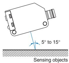
Detection of Glossy Objects
Mount the Sensor at an angle of 5^ to 15^ , as shown in the following diagram. This will improve the mark detection capability.
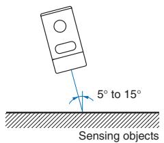
Operating Procedure
Two-point Teaching Using Teaching Button
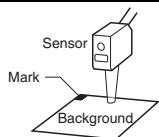
- Place the point for which you want the output to go ON in the beam spot position. Then, press and hold the teaching button for at least 2 seconds.
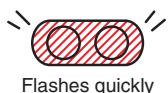
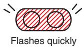
The teaching indicator (red) will begin flashing quickly. (This indicates that the output ON teaching operation should begin.) Perform the following operation within 7 seconds of when you start pushing the button. (After 7 seconds, the Unit will return to its initial condition.)
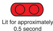
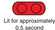
- Press the teaching button for approximately 0.5 second. The teaching indicator (red) will light for approximately 0.5 second to show that the output ON teaching is completed.
The teaching indicator (red) will then begin flashing quickly again to show that the output OFF teaching operation should begin.
- Place the point where you want the output to go OFF in the beam spot position.
- Press the teaching button for approximately 0.5 second. The teaching indicator (red) will light for approximately 0.5 second to show that the output OFF teaching is completed.
When Teaching Is Successful
The stability indicator (green) shows that detection is stable.
1Lights
→Thisindicatesstable detection, evenif thereis somefluttering in the sensing object.
- Flashes
→Thisindicates the possibility of unstable detection, due to fluttering in the sensing object.
3.Remains OFF
→Thisindicatesunstable detection.


Flashes

Off
When Teaching Is Not Successful
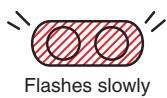
The teaching indicator (red) flashes slowly.
(Flashes in cycles of approx. 6 seconds.)
Repeat the operation starting with step 1.

The Sensor enters normal operating condition.
| Stable detection | Unstable detection | |
| ON point | Lit Lit | Off Lit |
| OFF point | Lit Off | Off Off |
Automatic teaching (Remote)
- Send a pulse with a duration of at least 2 s but less than 10 s min. to the remote control input (pink).
- Teaching will be performed automatically when the mark (the light level with the shorter detection time) passes through the beam spot.
Make sure the mark passes through the beam spot for at least 1.5 ms.
Pass the mark through the beam spot at least seven times to complete the teaching process.
There must be a difference in light intensity between the mark and the background for teaching to be successful.
- Detection will begin and the output will turn ON when the mark (the light level with the shorter detection time) is detected.
Note: Determine when teaching has been completed by confirming that the output turns ON for the mark and OFF for the background. If the output does not turn ON for the mark and OFF for the background within one minute after the remote control input is applied, teaching has not been successful. Apply the remote control input again.
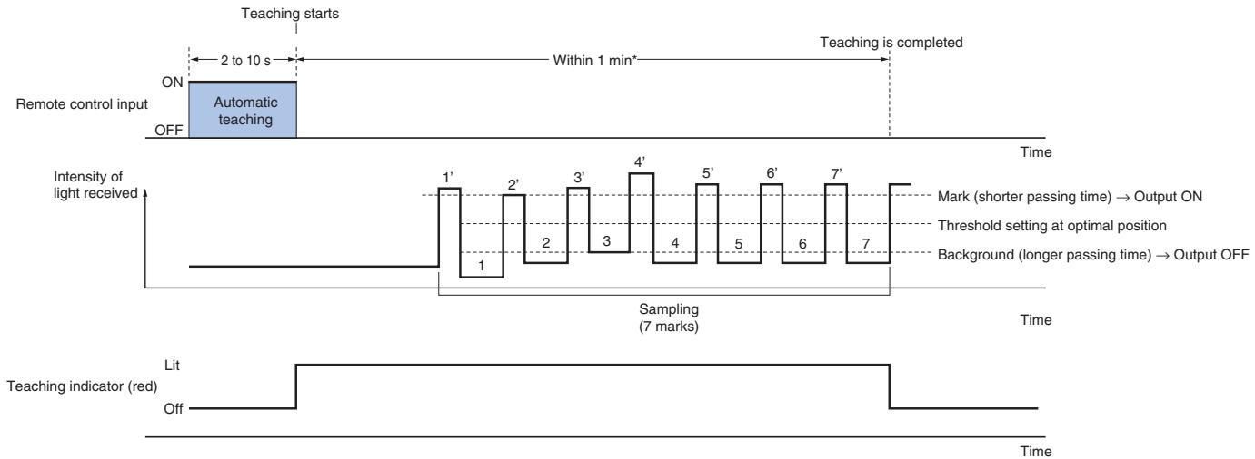
*If seven marks do not pass within one minute of the remote control input, the teaching operation will be cancelled.
Precautions for Using Automatic Teaching (Remote)
- With automatic teaching (remote), the output is always turned ON for the light level with the shorter detection time. Use 2-point teaching (manual) to turn OFF the output for the light level with the shorter detection time.
- Faulty detection is possible when using automatic teaching (remote) if there is considerable movement in the sensing object or if the surface of the object is stepped or contains protrusions.
In cases such as these, use 2-point teaching.
- Do not use automatic teaching for backgrounds that are not monochrome.
Sensors
Mark Sensor
(Diffuse reflective)
Pre-wired Models
E3ZM-V61
E3ZM-V81
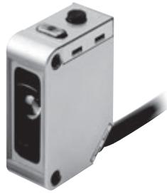
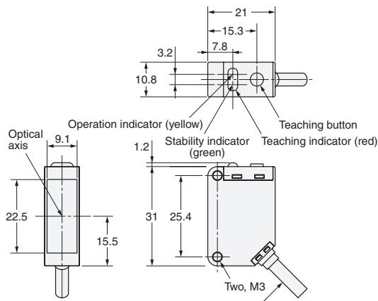
4-dia. Vinyl-insulated round cable with 4 conductors
Conductor cross section: 0.2mm^2 (AWG.24), Insulator diameter: 1.1mm , Standard length: 2m
Mark Sensor
(Diffuse reflective)
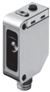
M8 Connector
E3ZM-V66
E3ZM-V86
READ AND UNDERSTAND THIS DOCUMENT
Please read and understand this document before using the products. Please consult your OMRON representative if you have any questions or comments.
WARRANTY
OMRON's exclusive warranty is that the products are free from defects in materials and workmanship for a period of one year (or other period if specified) from date of sale by OMRON.
OMRON MAKES NO WARRANTY OR REPRESENTATION, EXPRESS OR IMPLIED, REGARDING NON-INFRINGEMENT, MERCHANTABILITY, OR FITNESS FOR PARTICULAR PURPOSE OF THE PRODUCTS. ANY BUYER OR USER ACKNOWLEDGES THAT THE BUYER OR USER ALONE HAS DETERMINED THAT THE PRODUCTS WILL SUITABLY MEET THE REQUIREMENTS OF THEIR INTENDED USE. OMRON DISCLAIMS ALL OTHER WARRANTYES, EXPRESS OR IMPLIED.
LIMITATIONS OF LIABILITY
OMRON SHALL NOT BE RESPONSIBLE FOR SPECIAL, INDIRECT, OR CONSEQUENTIAL DAMAGES, LOSS OF PROFITS OR COMMERCIAL LOSS IN ANY WAY CONNECTED WITH THE PRODUCTS, WHETHER SUCH CLAIM IS BASED ON CONTRACT, WARRANTY, NEGLIGENCE, OR STRICT LIABILITY.
In no event shall responsibility of OMRON for any act exceed the individual price of the product on which liability is asserted.
IN NO EVENT SHALL OMRON BE RESPONSIBLE FOR WARRANTY, REPAIR, OR OTHER CLAIMS REGARDING THE PRODUCTS UNLESS OMRON'S ANALYSIS CONFIRMS THAT THE PRODUCTS WERE PROPERLY HANDLED, STORED, INSTALLED, AND MAINTAINED AND NOT SUBJECT TO CONTAMINATION, ABUSE, MISUSE, OR INAPPROPRIATE MODIFICATION OR REPAIR.
SUITABILITY FOR USE
THE PRODUCTS CONTAINED IN THIS DOCUMENT ARE NOT SAFETY RATED. THEY ARE NOT DESIGNED OR RATED FOR ENSURING SAFETY OF PERSONS, AND SHOULD NOT BE RELIED UPON AS A SAFETY COMPONENT OR PROTECTIVE DEVICE FOR SUCH PURPOSES. Please refer to separate catalogs for OMRON's safety rated products.
OMRON shall not be responsible for conformity with any standards, codes, or regulations that apply to the combination of products in the customer's application or use of the product.
At the customer's request, OMRON will provide applicable third party certification documents identifying ratings and limitations of use that apply to the products. This information by itself is not sufficient for a complete determination of the suitability of the products in combination with the end product, machine, system, or other application or use.
The following are some examples of applications for which particular attention must be given. This is not intended to be an exhaustive list of all possible uses of the products, nor is it intended to imply that the uses listed may be suitable for the products:
- Outdoor use, uses involving potential chemical contamination or electrical interference, or conditions or uses not described in this document.
- Nuclear energy control systems, combustion systems, railroad systems, aviation systems, medical equipment, amusement machines, vehicles, safety equipment, and installations subject to separate industry or government regulations.
- Systems, machines, and equipment that could present a risk to life or property.
Please know and observe all prohibitions of use applicable to the products.
NEVER USE THE PRODUCTS FOR AN APPLICATION INVOLVING SERIOUS RISK TO LIFE OR PROPERTY WITHOUT ENSURING THAT THE SYSTEM AS A WHOLE HAS BEEN DESIGNED TO ADDRESS THE RISKS, AND THAT THE OMRON PRODUCT IS PROPERLY RATED AND INSTALLED FOR THE INTENDED USE WITHIN THE OVERALL EQUIPMENT OR SYSTEM.
PERFORMANCE DATA
Performance data given in this document is provided as a guide for the user in determining suitability and does not constitute a warranty. It may represent the result of OMRON's test conditions, and the users must correlate it to actual application requirements. Actual performance is subject to the OMRON Warranty and Limitations of Liability.
CHANGE IN SPECIFICATIONS
Product specifications and accessories may be changed at any time based on improvements and other reasons.
It is our practice to change model numbers when published ratings or features are changed, or when significant construction changes are made. However, some specifications of the product may be changed without any notice. When in doubt, special model numbers may be assigned to fix or establish key specifications for your application on your request. Please consult with your OMRON representative at any time to confirm actual specifications of purchased products.
DIMENSIONS AND WEIGHTS
Dimensions and weights are nominal and are not to be used for manufacturing purposes, even when tolerances are shown.
ERRORS AND OMISSIONS
The information in this document has been carefully checked and is believed to be accurate; however, no responsibility is assumed for clerical, typographical, or proofreading errors, or omissions.
PROGRAMMABLEPRODUCTS
OMRON shall not be responsible for the user's programming of a programmable product, or any consequence thereof.
COPYRIGHT AND COPY PERMISSION
This document shall not be copied for sales or promotions without permission.
This document is protected by copyright and is intended solely for use in conjunction with the product. Please notify us before copying or reproducing this document in any manner, for any other purpose. If copying or transmitting this document to another, please copy or transmit it in its entirety.
Cat. No. E389-E2-01-X
In the interest of product improvement, specifications are subject to change without notice.
OMRON EUROPE B.V.
Wegalaan 67-69,
- Print mark detection photoelectric sensor in compact stainless steel housing
- E3ZM-V
- Features
- Reliable print mark detection within OMRON's most popular E3Z sensor family
- - Space-saving design with an SUS316L housing
- Coaxial optical system
- Water and detergent resistance
- Reliable detection of differently colored print marks due to RGB signal processing
- - RGB signal processing
- - Easy setting with 2-point or automatic teaching
- 2-point Teaching (Manual)
- Automatic Teaching (Remote)
- Ordering Information
- Accessories
- Color vs. Detection Capability
- Detectable Ranges
- I/O Circuit Diagrams
- Plugs (Sensor I/O Connectors)
- Safety Precautions
- WARNING
- CAUTION
- Precautions for Safe Use
- Connecting Connectors
- Load
- Oily Environments
- Modifications
- Outdoor Use
- Cleaning
- Surface Temperature
- Cable Bending
- Precautions for Correct Use
- Operating Procedure
- When Teaching Is Successful
- When Teaching Is Not Successful
- Precautions for Using Automatic Teaching (Remote)
- Sensors
- READ AND UNDERSTAND THIS DOCUMENT
- WARRANTY
- LIMITATIONS OF LIABILITY
- SUITABILITY FOR USE
- PERFORMANCE DATA
- CHANGE IN SPECIFICATIONS
- DIMENSIONS AND WEIGHTS
- ERRORS AND OMISSIONS
- PROGRAMMABLEPRODUCTS
- COPYRIGHT AND COPY PERMISSION
- OMRON EUROPE B.V.
Brand : OMRON
Model : E3ZM-V
Category : Proximity Sensors