
E2Q2 - Proximity Sensors OMRON - Free user manual and instructions
Find the device manual for free E2Q2 OMRON in PDF.


| Product Type | Proximity Sensor |
| Brand | OMRON |
| Model | E2Q2 |
| Detection Distance | 15 mm or 30 mm (shielded) |
| Output Type | NO, NC, NO+NC (depending on model) |
| Power Supply | AC or DC (depending on model) |
| Connection | M20x1.5 or 1/2" NPT conduit |
| Active Face | Removable (changeable) |
| Weld Field Resistance | Up to 100 mT (specific models) |
| Main Functions | Detection of metallic object presence |
| Maintenance and Cleaning | Clean with a dry cloth |
| Safety | Follow the instructions in the user manual |
| Spare Parts and Repairability | Contact OMRON customer service |
| General Information | Industrial proximity sensor, available in AC and DC versions |
Frequently Asked Questions - E2Q2 OMRON
User questions about E2Q2 OMRON
0 question about this device. Answer the ones you know or ask your own.
Ask a new question about this device
Download the instructions for your Proximity Sensors in PDF format for free! Find your manual E2Q2 - OMRON and take your electronic device back in hand. On this page are published all the documents necessary for the use of your device. E2Q2 by OMRON.
USER MANUAL E2Q2 OMRON
Long Distance Square Inductive Proximity Sensor
E2Q2
- Terminal Housing
Active face direction changeable - Easy to install and same mounting dimensions as a standard style electro-mechanical limit switch
- Integrated short circuit and reverse polarity protection
- Robust body with stainless steel screws
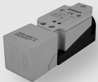
Square Proximity Sensor
C E
Ordering Information
DC type
| Sensing distance | Connection | Active face | Output | ||
| NO | NO + NC | ||||
| 20 mm shielded | Terminals | Changeable | NPN | E2Q2-N20E1-H | E2Q2-N20E3-☐ |
| PNP | E2Q2-N20F1-H | E2Q2-N20F3-☐ | |||
| 30 mm non-shielded | NPN | E2Q2-N30ME3-☐ | |||
| PNP | E2Q2-N30MF3-☐ | ||||
| 40 mm non-shielded | NPN | E2Q2-N40ME3-☐ | |||
| PNP | E2Q2-N40MF3-☐ | ||||
| Item\Model | shielded | non-shielded | ||
| E2Q2-N15F1-51 weld-immune type | E2Q2-N20□□-□ | E2Q2-N30□□-□ | E2Q2-N40□□-□ | |
| Sensing distance Sn | 15 mm ± 10% | 20 mm ± 10% | 30 mm ± 10% | 40 mm ± 10% |
| Standard target size, L x W x H, Fe 37 | 45 x 45 x 1 mm | 60 x 60 x 1 mm | 90 x 90 x 1 mm | 120 x 120 x 1 mm |
| Setting distance | 0 to 12,15 mm | 0 to 16,2 mm | 0 to 24,3 mm | 0 to 32,4 mm |
| Switching frequency | 10 Hz (weld-field im-mune type) | 150 Hz | 100 Hz | 30 Hz |
| Sensing object | Ferrous metals | |||
| Differential travel | 15% max. of sensing distance Sn | |||
| Operating voltage | 10 to 30 VDC | 10 to 60 VDC | ||
| Current consumption | 20 mA max. | 10 mA max. | 20 mA max. | |
| Control output Type | E2Q2-N□□□E1-□□: NPN - NO E2Q2-N□□□E3-□□: NPN - NO + NC E2Q2-N□□□F1-□□: PNP - NO E2Q2-N□□□F3-□□: PNP - NO + NC | |||
| Load | 200 mA max. | |||
| On-stage voltage drop | 3 VDC max. (at 200 mA load current) | |||
| Circuit protection | Reverse polarity, output short circuit | |||
| Alternating magnetic field | 100 mT | --- | ||
| Indicator | Operating indicator (yellow LED), operating voltage (green LED) | |||
| Ambient temperature | Operating: -25° to 70°C | |||
| Ambient humidity | 35 to 95% RH | |||
| Influence of temperature | ± 10% max. of Sn at 23° in temperature range of -25° to 70°C | |||
| Dielectric strength | 1.500 VAC, 50/60 Hz for 1 min. between current carry parts and case | |||
| Electromagnetic compatibility EMC | EN 60947-5-2 | |||
| Vibration resistance | 10 to 55 Hz, 1 mm amplitude according IEC 60068-2-6 | |||
| Shock resistance | Approx. 30 G for 11 ms according to IEC 60068-2-27 | |||
| Protection degree | IEC 60529 IP 67 | |||
| Connection Terminals | Up to 2,5 mm² | |||
| Material Case Terminal base | PBT AI PBT (...H type) | |||
| Sensing face | PBT | |||
| Approvals | CERTIFIED ULListED | |||
AC type
| Item | Model | shielded | non-shielded | |
| E2Q2-N15Y4-51 weld-immune type | E2Q2-N15□□-□ | E2Q2-N30□□-□ | ||
| Sensing distance Sn | 15 mm ± 10% | 30 mm ± 10% | ||
| Standard target size, L x W x H, Fe 37 | 45 x 45 x 1 mm | 90 x 90 x 1 mm | ||
| Setting distance | 0 to 12,15 mm | 0 to 24,3 mm | ||
| Switching frequency | 20 Hz | |||
| Sensing object | Ferrous metals | |||
| Differential travel | 15% max. of sensing distance Sn | |||
| Operating voltage | 20 to 253 VAC | |||
| Off-state current | 2,5 mA max. | 1,9 mA max. | ||
| Control output | Type | AC - NO or NC | ||
| Load | 500 mA max. | |||
| 10 mA min. | 8 mA min. | |||
| On-stage voltage drop | 12 VAC max. (at 500 mA load current) | |||
| Circuit protection | --- | |||
| Alternating magnetic field | 100 mT | --- | ||
| Indicator | Operating indicator (yellow LED), operating voltage (green LED) | |||
| Ambient temperature | Operating: -25° to 70°C | |||
| Ambient humidity | 35 to 95% RH | |||
| Influence of temperature | ± 10% max. of Sn at 23° in temperature range of -25° to 70°C | |||
| Dielectric strength | 1.500 VAC / 2500 VAC (E2Q2-…-H), 50/60 Hz for 1 min. between current carry parts and case | |||
| Electromagnetic compatibility EMC | EN 60947-5-2 | |||
| Vibration resistance | 10 to 55 Hz, 1 mm amplitude according IEC 60068-2-6 | |||
| Shock resistance | Approx. 30 G for 11 ms according to IEC 60068-2-27 | |||
| Protection degree | IEC 60529 IP 67 | |||
| Connection | Terminals | Up to 2,5 mm² | ||
| Material | Case Terminal base | PBT AI PBT (...-H type) | ||
| Sensing face | PBT | |||
| Approvals | CERTIFIED ULListED | |||
Output Circuit Diagram
NPN output
| Model | Operation mode | Timing chart | Output circuit |
| E2Q2-N20E1-H | NO | Sensing zone Sensing zone Sensing object (%) 100 distance 0 ON OFF Control output | Brown ① +V Load Black ④ Blue ③ 0 V |
| E2Q2-N20E3- E2Q2-N30ME3- E2Q2-N40ME3- | NO + NC | Sensing zone Sensing zone Sensing object (%) 100 distance 0 ON OFF Control output NC | Brown ① +V Load Black ④ NO White ② NC Blue ③ 0 V |
PNP output
| Model | Operation mode | Timing chart | Output circuit |
| E2Q2-N20F1-H | NO | Sensing zone Sensing zone Sensing object Proximity Sensor | Brown ① +V |
| E2Q2-N15F1-51 | (%) 100 distance Rated ON Yellow indicator | Black ④ Load | |
| ON OFF | 4.7kΩ | ||
| ON OFF | Blue ③ 0 V | ||
| E2Q2-N20F3- | NO + NC | Sensing zone Sensing zone Sensing object Proximity Sensor | Brown ① +V |
| E2Q2-N30MF3- | (%) 100 distance Rated ON Yellow indicator | White ② | |
| E2Q2-N40ME3- | ON OFF | NC Black ④ Load | |
| ON OFF | 4.7kΩ | ||
| ON OFF | Blue ③ 0 V |
AC output
| Model | Operation mode | Timing chart | Output circuit |
| E2Q2-N15Y4-51 | NO or NC | Non-sensing zone Sensing zone Sensing object (%) 100 distance range ON OFF Yellow indicator ON OFF Control output NO ON OFF Control output NC | Brown ③ Blue ④ Load ① White ② Load ① Operation Indicator (yellow) Note: Only one load allowed! |
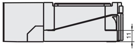
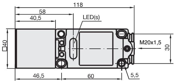
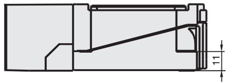
E2Q2-...H type
E2Q2-...-U and -51 type
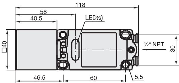
Connection
DC type
| Connection type | Method | Description |
| AND (serial connection) | Correct | The Sensors connected together must satisfy the following conditions: iL + (N-1) x i ≤ Upper-limit of control output of each Sensor Vs - N x VR ≥ Load operating voltage N = No. of Sensors VR = Residual voltage of each Sensor Vs = Supply voltage i = Current consumption of the Sensor iL = Load current If the MY Relay, which operate at 24 VDC, is used as a load for example, a maximum of two Proximity Sensors can be connected to the load. |
| OR (parallel connection) | Correct | A minimum of three Sensors with current outputs can be connected in parallel. The number of Sensors connected in parallel varies with the Proximity Sensor model. |
AC type
| Connection type | Method | Description |
| AND (serial connection) | Incorrect Correct X1 X2 Load V1 V2 V3 X4 X5 | If 100 or 200 VAC is imposed on the Proximity Sensors, VL (i.e., the voltage imposed on the load) will be obtained from the following. VL=Vs-(residual voltage x no. of Proximity Sensors) (V) Therefore, if VL is lower than the load operating voltage, the load will not operate. A maximum of three Proximity Sensors can be connected in series pro- vided that the supply voltage is 100 V minimum. |
| OR (parallel connec- tion) | Incorrect A B Correct A B C Load A B C Load VAC power supply V5 | In principle, more than two Proximity Sensors cannot be connected in parallel. Provided that Proximity Sensor A does not operate with Proximity Sen- sor B simultaneously and there is no need to keep the load operating continuously, the Proximity Sensors can be connected in parallel. In this case, however, due to the total leakage current of the Proximity Sensors, the load may not reset properly. It is not possible to keep the load operating continuously with Proximity Sensors A and B in simultaneous operation to sense sensing objects due to the following reason. When Proximity Sensor A is ON, the voltage imposed on Proximity Sen- sor A will drop to approximately 10 V and the load current flows into Prox- imuthy Sensor A, and when one of the sensing objects is close to Proximity Sensor B, Proximity Sensor B will not operate because the voltage im- posed on Proximity Sensor B is 10 V, which is too low. When Proximity Sensor A is OFF, the voltage imposed on Proximity Sen- sor B will reach the supply voltage and Proximity Sensor B will be ON. Then, Proximity Sensor A as well as Proximity Sensor B will be OFF for approximately 10 ms, which resets the load for an instant. To prevent the instantaneous resetting of the load, use a relay as shown on the left. |

Caution
Power supply
Do not impose an excessive voltage on the E2Q2, otherwise it may explode or burn.
Do not connect an AC power supply to any DC model. If AC power (100 VAC or more) is supplied to the sensor, it may explode or burn.
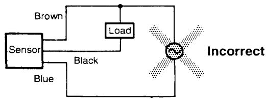
Do not connect the AC types without load to the power supply. The sensor will be damaged.
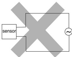
Be sure to abide by the following precautions for the safe operation of the Sensor.
Wiring
Power Supply Voltage and Output Load Power Supply Voltage
Make sure that the power supply to the Sensor is within the rated voltage range. If a voltage exceeding the rated voltage range is supplied to the Sensor, it may explode or burn.
Load Short-circuiting
Do not short-circuit the load, otherwise the Sensor may be damaged.
Connection without Load
Do not connect the power supply to the Sensor with no load connected, otherwise the internal elements may explode or burn.
Operating Environment
Do not use the Sensor in locations with explosive or flammable gas.
Correct Use
Design
Effects of Surrounding Metal
Provide a minimum distance between the Sensor and the surrounding metal as shown in the table below.
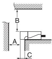
Effects of Surrounding Metal (Unit: mm)
| Model | Length | A | B | C |
| E2Q2-N15□□-□□E2Q2-N20□□-□□ | 45 | 0 | 0 | |
| E2Q2-N30M□□-□□ | 90 | 250 | 30 | |
| E2Q2-N40M□□-□□ | 120 | 300 | 40 | |
Mutual Interference
If more than one Sensor is located in parallel, ensure to maintain enough space between adjacent Sensors to suppress mutual interference as provided in the following diagram.
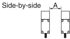
Mutual Interference (Unit: mm)
| Model | Length | A |
| E2Q2-N15□□-□□ | 40 | |
| E2Q2-N20□□-□ | ||
| E2Q2-N30M□□-□ | 120 | |
| E2Q2-N40M□□-□ | 150 | |
Power Reset Time
The Sensor is ready to operate within 300 ms after the Sensor is turned ON. If the load and Sensor are connected to independent power supplies respectively, be sure to turn ON the Sensor before supplying power to the load.
Power OFF
The Proximity Sensor may output a pulse signal when it is turned OFF. Therefore, it is recommended that the load be turned OFF before turning OFF the Proximity Sensor.
Power Supply Transformer
When using a DC power supply, make sure that the DC power supply has an insulated transformer. Do not use a DC power supply with an auto-transformer.
Sensing Object
The sensing distance of the Proximity Sensor vary with the metal coating on sensing objects.
Wiring
High-tension cables
Wiring through Metal Conduit:
If there is power or high-tension line near the cable of the Proximity Sensor, wire the cable through an independent metal conduit to prevent against Proximity Sensor damage or malfunction.
Mounting
Mounting the Sensor
The Proximity Sensor must be subjected to excessive shock with a hammer when it is installed, otherwise the Proximity Sensor may be damaged or lose its water-resistivity.
Maintenance and Inspection
Periodically perform the following checks to ensure stable operation of the Proximity Sensor over a long period of time.
- Check for mounting position, dislocation, looseness or distortion of the Proximity Sensor and sensing objects.
- Check for loose wiring and connections, improper contacts and line breakage.
- Check for attachment or accumulation of metal powder or dust.
- Check for abnormal temperature conditions and other environmental conditions.
Never disassemble or repair the Sensor.
Environment
Water Resistivity
Do not use the Proximity Sensor underwater, outdoors or in the rain.
Operating Environment
Be sure to use the Proximity Sensor within its operating ambient temperature range and do not use the Proximity Sensor outdoors so that its reliability and life expectancy can be maintained. Although the Proximity Sensor is water resistive, a cover to protect the Proximity Sensor from water or water-soluble machining oil is recommended so that its reliability and life expectancy can be maintained.
Do not use the Proximity Sensor in an environment with chemical gas (e.g., strong alkaline or acid gasses including nitric, chromic and concentrated sulfuric acid gases).
Inrush Current
A load that has a large inrush current (e.g., a lamp or motor) will damage the Proximity Sensor, in this case connect the load to the Proximity Sensor through a Relay
ALL DIMENSIONS SHOWN ARE IN MILLIMETERS.
To convert millimeters into inches, multiply by 0.03937. To convert grams into ounces, multiply by 0.03527.
- Long Distance Square Inductive Proximity Sensor
- E2Q2
- Ordering Information
- Output Circuit Diagram
- Connection
- Power supply
- Wiring
- Load Short-circuiting
- Connection without Load
- Operating Environment
- Correct Use
- Design
- Mutual Interference
- Power Reset Time
- Power OFF
- Power Supply Transformer
- Sensing Object
- High-tension cables
- Mounting
- Mounting the Sensor
- Maintenance and Inspection
- Environment
- Water Resistivity
- Inrush Current
Brand : OMRON
Model : E2Q2
Category : Proximity Sensors