
E3MC - Proximity Sensors OMRON - Free user manual and instructions
Find the device manual for free E3MC OMRON in PDF.


| Product type | Color (RGB) proximity sensor with ON/OFF or analog output |
| Brand | OMRON |
| Model | E3MC (versions: A, X, Y, MA, MX, MY, A81, X81, Y81) |
| Category | Proximity sensors |
| Power supply | ON/OFF: 12 to 24 VDC ±10%; Analog: 24 VDC ±10% |
| Power consumption | Max. 100 mA |
| Detection distance (built-in amplifier type) | 60 ± 10 mm |
| Detection distance (fiber optic type) | 20 ± 4 mm |
| Light source | Red LED (680 nm), green (525 nm), blue (450 nm) |
| Number of distinguishable colors | Up to 90 colors (with standard object) |
| Operating temperature | -20 to 55 °C (no frost) |
| Protection rating | IP66 (with protective cap) |
| Weight (built-in amplifier type) | Approx. 350 g |
| Weight (fiber optic type) | Approx. 400 g |
| Housing material | Die-cast zinc (zinc alloy) |
| Control outputs | 1 or 4 NPN/PNP open collector outputs (depending on version) |
| Main functions | Color discrimination (C or I mode), teaching, threshold adjustment, OFF timer 40 ms, external synchronous input |
| Maintenance and cleaning | Clean the lens with a soft, dry cloth; check connection tightness |
| Safety | Protection against load short-circuits and reverse polarity |
| Spare parts and repairability | E39-C1 connectors (2 m or 5 m), E39-L114/E39-L115 mounting brackets, recommended fiber optics (e.g., E32-DC200, E32-CC200) |
| General information | LED lifespan: several tens of thousands of hours; maintenance-free replacement |
Frequently Asked Questions - E3MC OMRON
User questions about E3MC OMRON
0 question about this device. Answer the ones you know or ask your own.
Ask a new question about this device
Download the instructions for your Proximity Sensors in PDF format for free! Find your manual E3MC - OMRON and take your electronic device back in hand. On this page are published all the documents necessary for the use of your device. E3MC by OMRON.
USER MANUAL E3MC OMRON
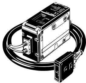
Color sensor (LED type)
E3MC
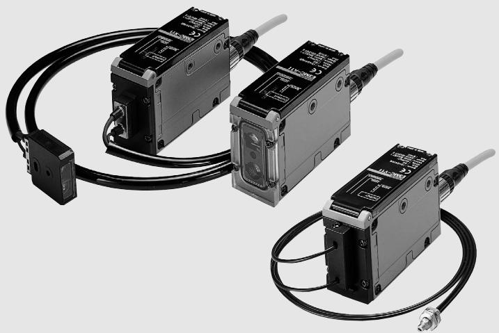
RGB Color Sensor Discriminates Delicate Differences in Color.
C E
Features
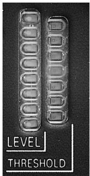
Double Indication ensuring high visibility.
- Conformity with the registered colors can be monitored at eight levels. (Detection level indicators)
- Allows fine adjustment between fine or rough discrimination while monitoring the measured results. (Threshold level indicators)
Stable and Powerful Detection for Inline Use
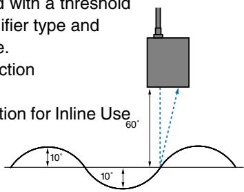
Stable detection is assured with a threshold of ± 10mm for built-in amplifier type and ± 4mm for optical fiber type.
Fiber type and Stable detection ± 4 mm.
Stable and Powerful Detection for Inline Use
Mounting is easy.
Long-distance Sensing with Built-in Amplifier Type
Built-in amplifier type with a sensing distance of 60 ± 10 ~mm is available for a wide range of color discriminating applications.
Highly Resistant to Changes in Sensing Object Brightness and Ambient Temperature.
- OMRON's unique Free Angle Optics (FAO: multi-layer polarized filter) is highly resistant to changes in the tint or
brightness of sensing objects. Capable of discriminating over 90 different colors.
- Wide temperature range from -20^ to 55^ and excellent detection stability.
Maintenance-free LED Light Source
Incorporates RGB LED light sources with a long service life more than several tens of thousand hours.
Great maintenance-cost saver ensuring high performance (Halogen lamps used as light sources must be replaced or re-adjusted every nine months or so.)
Principle of Detection
The E3MC detects colors by making use of the fact that the reflection ratio of a primary color (i.e. red, green or blue) reflected by an object varies with the chromatically of the object. By using a high-tech, multi-layer polarized filter called FAO (free angle optics), the E3MC emits red, green and blue light on a single optical axis. The E3MC receives the light reflected by the sensing objects through the receiver and processes the red-green-blue ratio of the light to discriminate the color of the sensing object.
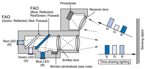
Note: The monitor photodiode compensates LED output deviation that may be caused by a temperature change. (Patent pending)
Application
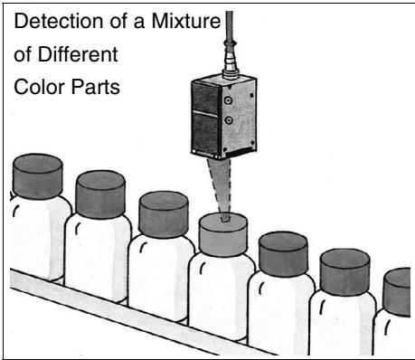
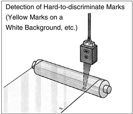
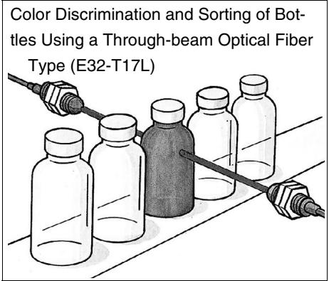
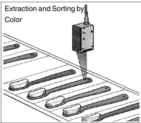
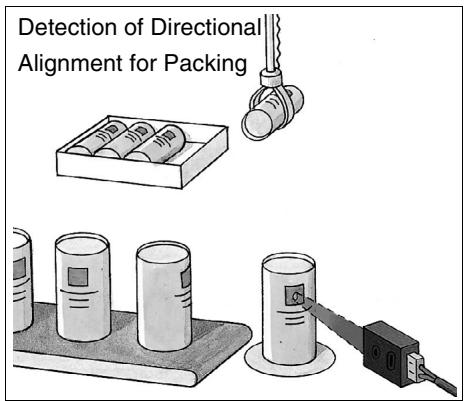
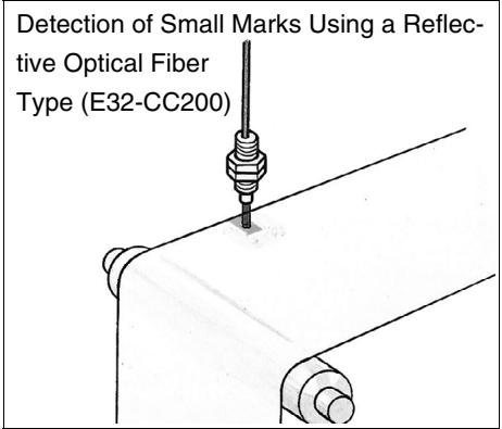
Features
Excellent Protective Structure and Maintenance Performance
The amplifier unit uses a sturdy metal body. The unit including the fiber head satisfies the water resistance of IEC Standard IP66. You can use the E3MC without any problems in a wide range of applications. In addition to this, the M12 metal connector has improved maintenance performance.
Discriminating Delicate Color Differences
The detection level indicators are lit according to the degree of conformity between registered and detected colors. Delicate color differences are discriminated by setting the threshold to a superior level. (Fine discrimination is expected.)
Sensor errors that may be caused by minor tint differences or dirt retention are prevented by setting the threshold to a lower level. (Rough discrimination is expected)
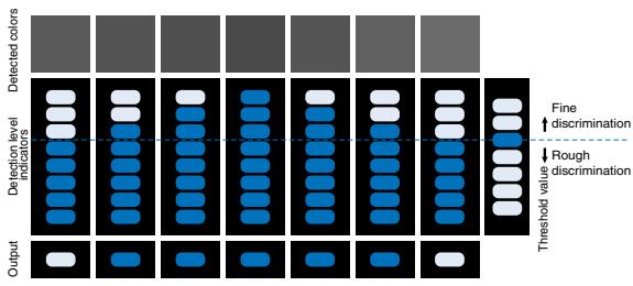
Conversion of Color Data into RGB Analog Data
The analog output type can control the color change history and distribution in analog form. Different type discrimination can also be performed without bank restrictions by CPU processing.
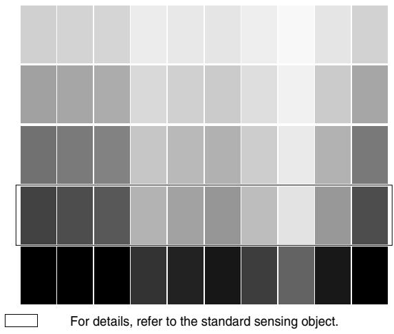
Color Chart
ON/OFF type
Red light, Green light, Blue light
Sensors
| Structure | No. of outputs | Shape | Connection method | Sensing distance | Model | ||||
| NPN output | PNP output | ||||||||
| Built-in Amplifier Type | 1 | Connector type Sensor I/O connec- tor (cable length 2 m) is supplied. | 60±10mm | E3MC-A11 | E3MC-A41 | ||||
| 4 | E3MC-MA11 | E3MC-MA41 | |||||||
| Optical Fiber Type | 1 | 20±4mm | E3MC-X11 | E3MC-X41 | |||||
| 4 | E3MC-MX11 | E3MC-MX41 | |||||||
| General-pur- pose Optical Fi- ber Type | 1 | E32-CC2005mm | *200mm | E3MC-Y11 | E3MC-Y41 | ||||
| 4 | E32-T16 | E3MC-MY11 | E3MC-MY41 | ||||||
Distance where 11 colors of standard sensing objects can be discriminated. As a typical example, 9 colors can be discriminated when 12mm is set. Please contact us since the sensing distance should be defined.
Analog output type
Accessories (Order Separately)
| Structure | Shape | Sensing distance | Model | ||
| Built-in Amplifier Type | 60±10mm | E3MC-A81 | |||
| Optical Fiber Type | 20±4mm | E3MC-X81 | |||
| General-purpose Optical Fiber Type | Using E32-CC200 5±1mm | E3MC-Y81 | |||
Sensor I/O Connectors
| Shape | Model | Quantity | Remarks |
| E39-C1 2M (2 m) | 1 pc. | Supplied with the product. | |
| E39-C1 5M (5 m) | 1 pc. | Please place an order when extending the cable. |
Mounting Brackets
| Shape | Model | Quanti- | Remarks |
| E39-L114 | 2 | For E3MC installation. (Can be inclined to 15°) | |
| E39-L115 | 1 | For DIN track installation. |
ON/OFF type
| Structure Item Model | Built-in Amplifier Type | Optical Fiber Type | General-purpose Optical Fiber | |||
| E3MC-A□1 | E3MC-MA□1 | E3MC-X□1 | E3MC-MX□1 | E3MC-Y□1 | E3MC-MY□1 | |
| Sensing distance | 60±10 mm*1 | 20±4 mm | Depends on the recommended fiber. Refer to page AB- for details. | |||
| Standard sensing object | *2 | |||||
| Spot diameter | 12 dia. | 3-mm dia. | - | |||
| Light source (wave length) | Red LED (680 mm), green LED (525 mm), blue LED (450 mm) | |||||
| Power supply voltage | 12 to 24 VDC ±10%, ripple (p-p): 10% max. | |||||
| Current consumption | 100 mA max. | |||||
| Control output | Load supply voltage 24 VDC max., load current 100 mA max. (residual voltage NPN output: 1.2 V max., PNP output: 2.0 V max.) Open collector output type | |||||
| Color discrimination mode | Mode C: RGB ratio detection, Mode I: RGB light intensity detection Switch selectable | |||||
| Output type | Conformity output: Output is ON when the detected color coincides with the registered color. Non-conformity output: Output is ON when the detected color does not coincide with the registered color. Switch selectable | |||||
| Mode selection | E3MC-□11/-□41 Mode A (Factory-set) Control output (white) Not used (gray) Bank selection input 1 (yellow) Bank selection input 2 (green) External synchronous inputs (pink) Voc (Brown) 0 V (Blue) Colors in parentheses are lead wire colors. | Mode B (for remote teaching) Control output (white) Answer-back output (gray) Remote control input (yellow) Not used External synchronous inputs (pink) Voc (Brown) 0 V (Blue) Colors in parentheses are lead wire colors. | ||||
| E3MC-M□11-/M□41 Mode A (Factory-set) Control output 1 (white) Control output 2 (gray) Control output 3 (yellow) Control output 4 (green) External synchronous inputs (pink) Voc (Brown) 0 V (Blue) Colors in parentheses are lead wire colors. | Mode B (for remote teaching) Control output 1 (white) Control output 2 (gray) Control output 3 (yellow) Answer-back output (green) Remote control input (pink) Voc (Brown) 0 V (Blue) Colors in parentheses are lead wire colors. | |||||
| Remote control input (B mode only) | The following control is performed according to the control signal input. E3MC-□11/-□41 Bank selection, remote teaching, or threshold selection E3MC-M□11/-M□41 channel selection, remote teaching, threshold changing | |||||
| Answer-back output (B mode only) | Load current: 100 mA max. NPN open collector output with a residual voltage of 1.2 V max. PNP open collector output with residual voltage 2.0 V max. (E3MC-(M)A41/-(M)X41/-(M)Y41) | |||||
| Bank selection input (1 output only) | Selected between 4 banks (switching with the bank selection input and select button) Bank selection input response time: 50 ms max. | |||||
| External synchronous input | Response time: 1 ms max. (Note that the 4 output type cannot be used when the B mode is selected) | |||||
| Protective circuits | Protection from load short-circuit and reversed power supply connection | |||||
| Response time | 1 output type: Standard mode: 3 ms max., high-speed mode: 1 ms max. (switch selectable) 4 output type: Standard mode: 6 ms max., high-speed mode: 2 ms max. (switch selectable) | |||||
| Discriminating color registration | 4 colors can be registered, teaching system (threshold permits fine adjustment) | |||||
| Timer function | OFF delay fixed at40 ms (ON/OFF switch selectable) | |||||
| Ambient illuminance | Incandescent lamp: 3,000 lux max. Sunlight 10,000 lux max. | |||||
| Ambient temperature | Operating: -20 to 55°C, Storage: -30 to 70°C (with no icing) | |||||
| Ambient humidity | Operating: 35% to 85% RH, Storage: 35% to 95% RH (with no icing or condensation) | |||||
| Permissible fiber bending radius | - | 10 mm min. | Varies with the type of recommended fiber | |||
| Insulation resistance | 20 M min. at 500 VDC | |||||
| Dielectric strength | 1,000 VAC at 50/60 Hz for 1 minute | |||||
| Vibration (resistance) *3 | Destruction: 10 to 55 Hz, 1.0 mm double amplitude or 150 m/s² for 2 hrs each in X, Y, and Z directions | |||||
| Shock (resistance) *4 | Destruction: 500 m/s² for 3 times each in X, Y, and Z directions | |||||
| Protective structure | IEC 60529 IP66 (with Protective Cover attached) | |||||
| Connection method | Connector type [sensor I/O connector (cable length 2 m)] | |||||
| Structure Item Model | Built-in Amplifier Type | Optical Fiber Type | General-purpose Optical Fiber | ||||
| E3MC -A□1 | E3MC -MA□1 | E3MC -X□1 | E3MC -MX□1 | E3MC -Y□1 | E3MC -MY□1 | ||
| Weight (Packed state) | Approx. 350 g | Approx. 400 g | Approx. 350 g | ||||
| Material | Case | Zinc die-cast | |||||
| Operation panel cover | PES | ||||||
| Fiber head | - | ABS | - | ||||
| Accessories | Cross-shaped recess screw M5x6 (with spring washer), sensor I/O connector (cable length 2 m), instruction manual | ||||||
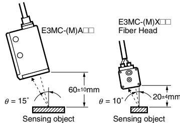
*1. C mode, standard mode (response time), threshold: Distance range where 11 colors of standard sensing objects can be discriminated when = 15^ (E3MC-(M) A□□) or = 10^ (E3MC-(M) X□□) in the following figure in the standard mode.
*2. Standard Sensing Objects
| Color (11 standard colors) | Munsell color notation |
| White | N9.5 |
| Red | 4R 4.5/12.0 |
| Yellow/red | 4YR 6.0/11.5 |
| Yellow | 5Y 8.5/11.0 |
| Yellow/green | 3GY 6.5/10.0 |
| Green | 3G 6.5/9.0 |
| Blue/green | 5BG 4.5/10.0 |
| Blue | 3PB 5.0/10.0 |
| Blue/purple | 9PB 5.0/10.0 |
| Purple | 7P 5.0/10.0 |
| Red/purple | 6RP 4.5/12.5 |
3. 0.75-mm double amplitude or 100m/s^2 when using a mounting bracket
4. 300m / s^2 when using a mounting bracket
Analog output type
| Structure Item | Model | Built-in Amplifier Type | Optical Fiber Type | General-purpose Optical Fiber Type |
| E3MC-A81 | E3MC-X81 | E3MC-Y81 | ||
| Sensing distance *1 | 60±10 mm | 20±4 mm | 5 ±1mm (When using the E32-CC200) | |
| Spot diameter | 12 dia. | 3-mm dia. | Varies with the recommended fiber. | |
| Light source (wave length) | Red LED (680 mm), green LED (525 mm), blue LED (450 mm) | |||
| Power supply voltage | 24 V DC ±10%, ripple (p-p) 10% or less | |||
| Power consumption | 100 mA max. | |||
| Control output | 3 analog independent outputs (RGB) 0 to 10 VDC without output short-circuit protection | |||
| Resolution | 300 mV max. | |||
| Load current | 5 mA max. | |||
| Response speed | 1.7 ms max. | |||
| Temperature drift | ±0.3% FS/°C max. | |||
| Power restoration time | 100 ms max. after power-on | |||
| Calibration input A, B | 24 VDC | |||
| Signal | 1 ms (24 VDC, HIGH active) | |||
| Response time | 600 ms max. | |||
| Calibration value | Terminal A: 10±0.2V | Terminal B: 7±0.2V | ||
| Protective circuits | Reverse polarity protection | |||
| Ambient illuminance | Incandescent lamp: Illumination on optical spot: 1,000 lux max. | |||
| Ambient temperature | Operating: 0°C to 50°C, Storage: -30°C to 70°C (with no icing or condensation) | |||
| Ambient humidity | Operating: 35% to 85%RH, Storage: 35% to 95%RH (with no condensation) | |||
| Permissible fiber bending radius | --- | 10 mm min. | Varies with the type of recommended fiber | |
| Insulation resistance | 20 M min. at 500 VDC | |||
| Dielectric strength | 1,000 VAC at 50/60 Hz for 1 minute | |||
| Vibration (resistance) *2 | Destruction: 10 to 55 Hz, 1.0 mm double amplitude or 150 m/s² for 2 hrs each in X, Y, and Z directions | |||
| Shock (resistance) *3 | Destruction: 500 m/s² for 3 times each in X, Y, and Z directions | |||
| Protective structure | IEC 60529 IP66 (with Protective Cover attached) | |||
| Connection method | M12 dedicated connector type | |||
| Weight (Packed state) | Approx. 300 g | Approx. 350 g | Approx. 300 g | |
| Material | Case | Zinc die-cast | ||
| Cover | PES | |||
| Fiber head | ABS | |||
| Accessories | Connection cable 2 m (E39-C1), instruction manual | |||
1. Distance range where calibration can be made with standard white paper (N9.5).
2. 0.75 mm double amplitude or 100m/s^2 when using a mounting bracket
*3. 300 m/s^2 when using a mounting bracket
Use (Typical)
NPN model

E3MC-11 (1 output type)
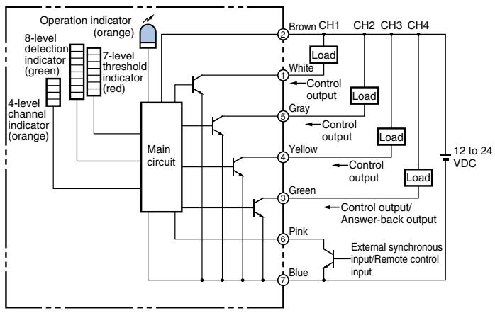
E3MC-M□11 (4 output type)
PNP type
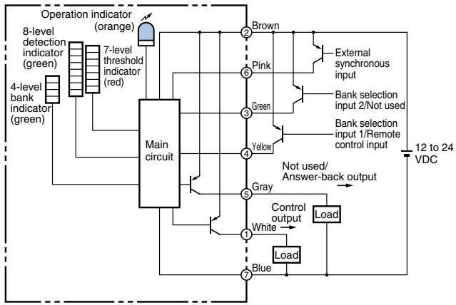
E3MC-□41 (1 output type)
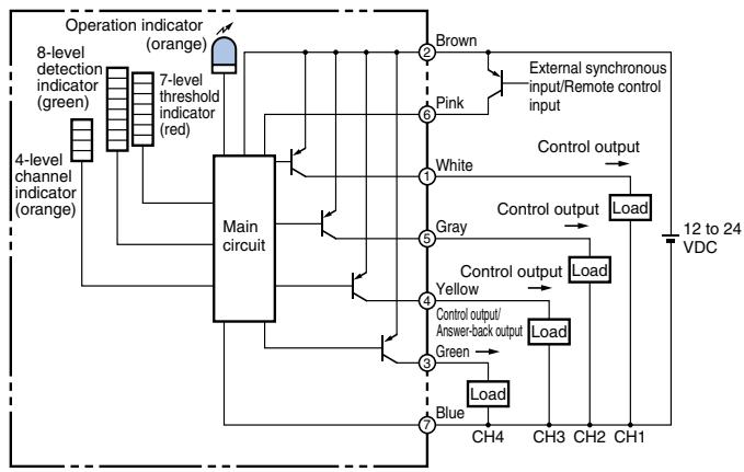
E3MC-M□41 (4 output type)
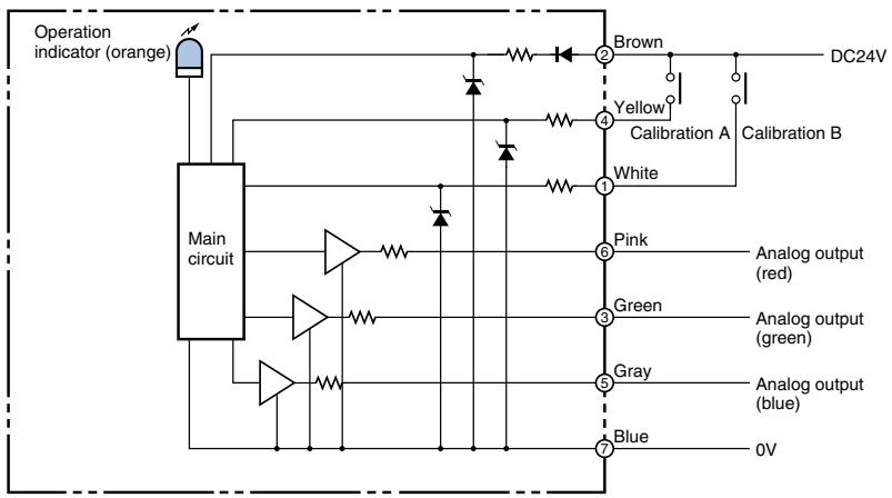
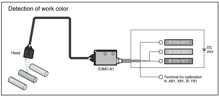
Analog output type
Connector Pin Arrangement
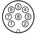
Note: Pin 8 in not used.
Timing chart
ON/OFF type
| Function Switch Color Conformity Selection | Output transistor Status | Timing chart | ||||||
| = (Upper side) | ON when colors coincide | Sensing object | Same color | Different color | Same color | Different color | Same color | |
| Discrimination result | ON OFF | |||||||
| External synchronous input | ON OFF | Output on hold | Output on hold | |||||
| Control output | ON OFF | This status can be on hold by an external synchronous input. It will be released by setting the external synchronous input to OFF. | This status can be on hold so that unwanted color objects can be ignored while they are passing the sensing range. | |||||
| ≠ (Lower side) | ON when colors do not coincide | Object | Different color | Same color | Different color | Same color | Different color | |
| Discrimination result | ON OFF | |||||||
| External synchronous input | ON OFF | Output on hold | Output on hold | |||||
| Control output | ON OFF | This status can be on hold by an external synchronous input. It will be released by setting the external synchronous input to OFF. | This status can be on hold so that unwanted color objects can be ignored while they are passing the sensing range, | |||||
Connectors (Sensor I/O connectors)
| Model | Internal Wiring | Pin No. | Wire color | ON/OFF type A mode | Analog output | ||
| E3MC-□11, E3MC-□41 | E3MC-M□11, E3MC-M□41 | E3MC-□81 | |||||
| E39-C1 2M (2 m) E39-C1 5M (5 m) | Lead wire color ① ② ③ ④ ⑤ ⑥ ⑦ Note: Pin 8 in not used. | ① | White | Output | Output 1 | Calibration B | |
| ② | Brown | Power supply (+V) | Power supply (+V) | Power supply (+V) | |||
| ③ | Green | Bank selection input 2 | Output 4 | Analog output G (green) | |||
| ④ | Yellow | Bank selection input 1 | Output 3 | Calibration A | |||
| 5 | Gray | - | Output 2 | Analog output B (blue) | |||
| 6 | Pink | External synchronous input | External synchronous input | Analog output R (red) | |||
| 7 | Blue | Power supply (0 V) | Power supply (0 V) | Power supply (0 V) | |||
ON/OFF type
E3MC-A□ (1 output Models)
E3MC-X□ (1 output Models)
E3MC-Y□ (1 output Models)
E3MC-MA (4 output Models)
E3MC-MX (4 output Models)
E3MC-MY (4 output Models)
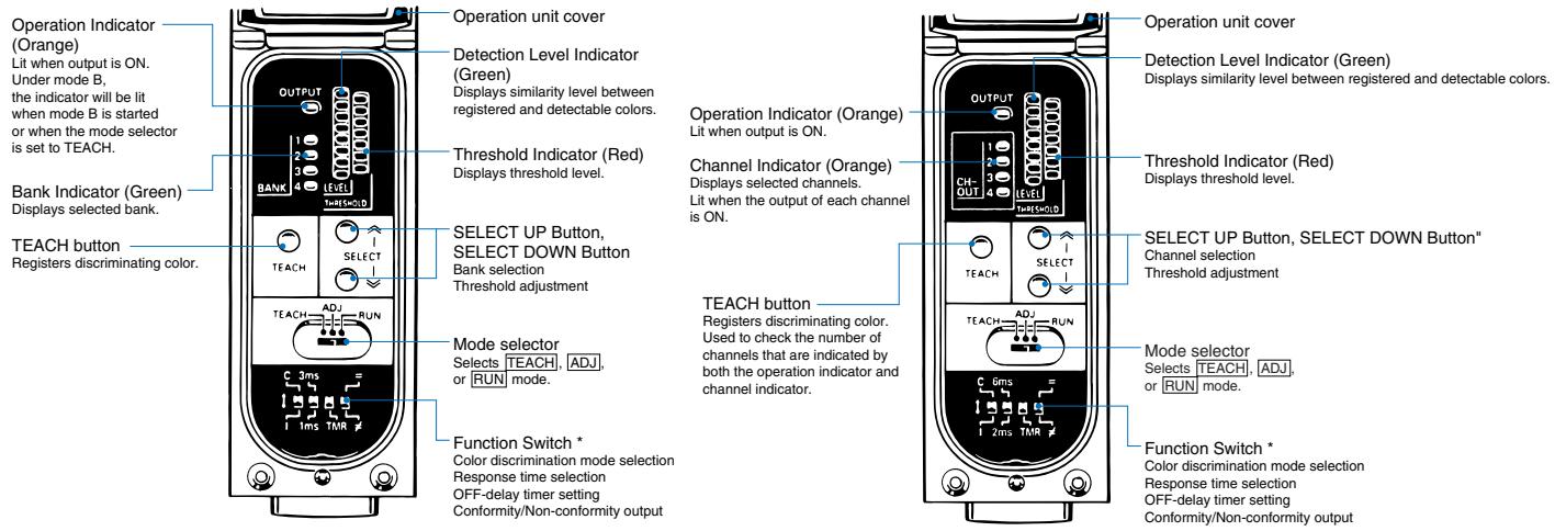
- Function Switches (Setting of various functions)
The following settings can be made with the function switches. (Settings can be made in the RUN mode or ADJ mode.) (For the 4 output type, all channels are the target of settings.)
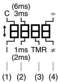
① Color Discrimination Mode Selection (Mode C is recommended for normal applications.)
Mode C: Color discrimination is performed according to R (red), G (green), and B (blue) ratio of the reflection light even if the sensing objects fluctuate up and down within the rated sensing range.
I (Mode I): Color discrimination is performed according to the light intensity. This mode ensures a finer color (similar colors or neutral color such as white, gray or black) discrimination than mode C.
- Response Time Selection (Note: Figures in parentheses are for the 4 output models.)
3 ms (6 ms): E3MC provides a stable detection of minute differences of color. Set the response
time to
3 ms for usual applications.
1 ms (2 ms): E3MC will be in quick-response operation. Set the response time to 1 ms if high-speed response is required.
- OFF-delay Timer Setting
No indication: No timer setting
TMR: A 40 ms OFF delay timer is set for control output.
- Conformity/Non-conformity Output
:= Output is ON when the detected color coincides with the registered color.
: Output is ON when the detected color does not coincide with the registered color.
Note: Each pin of the function switch is factory-set to the upper position.
Analog output type
Power indicator only
ON/OFF type
Setting Procedure
1-output Models (E3MC-A□/E3MC-X□/E3MC-Y□)
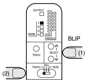
1. Bank Selection
Set the Mode Selector to the TEACH mode and then select the BANK using the SELECT button.
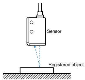
2. Color Registration
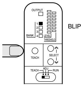
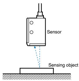
Locate the registered object at the detection point and press the TEACH button.
3. Threshold Adjustment (If Required)
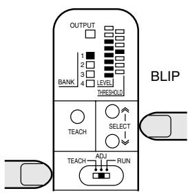
Place the sensing object, press the SELECT button in the ADJ mode, and make adjustment. (Adjustment can be made without a sensing object.) The bank selected in the ADJ mode is the bank selected in the TEACH or RUN mode.
Operation
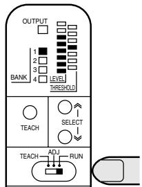
Make measurement in the RUN mode. The registered color can be selected with bank selection input.
Detection Level and Tolerance
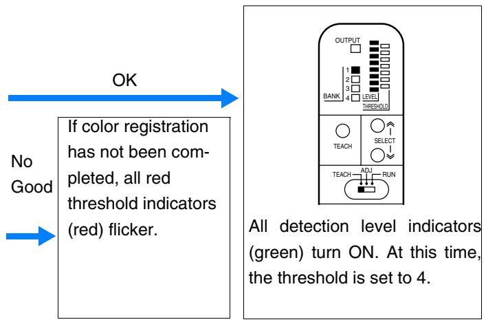
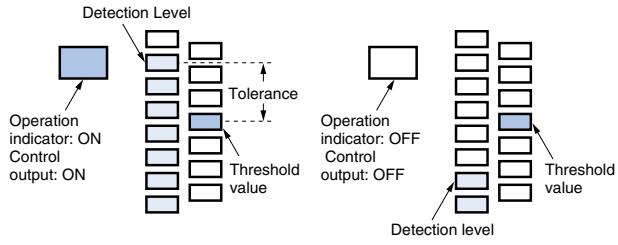
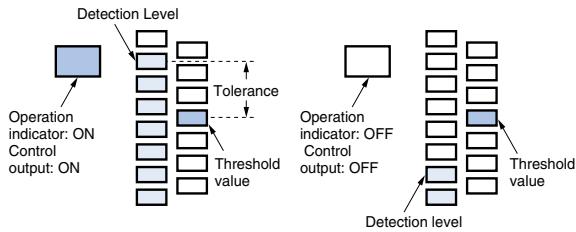
As the detected color becomes closer to the registered color (colors look alike), the number of lit detection level indicators (green) increase. The control output will turn ON if the detection level (green) exceeds the threshold level (red) and turn OFF if the detection level does not exceed the threshold level. (For conformity output setting) Set the threshold to a higher level for highly-precise color discrimination or to a lower level to allow margins for discriminated colors (ignore minor tint differences, dirt retention or like).
4 output Models (E3MC-MA□/E3MC-MX□/E3MC-MY□)
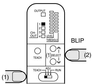
1. Channel Selection
Set the Mode Selector to the TEACH mode and then select the channel using the SELECT button.
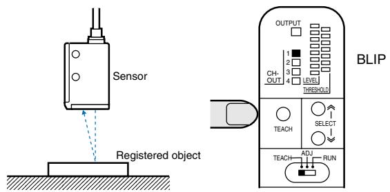
2. Color Registration
Locate the registered object at the detection point and press the TEACH button.
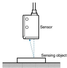
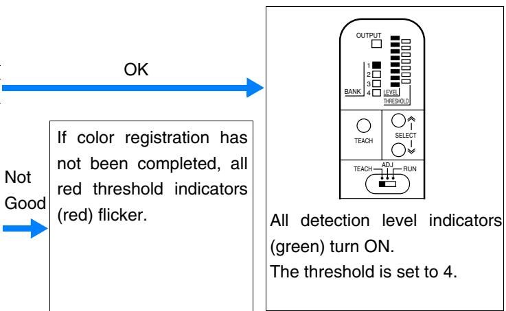
3. Threshold Adjustment (If Required)
ADJ
(Adjustment can be made without a sensing object)
The bank selected in the ADJ mode or TEACH mode will become the bank for the RUN mode.
Detection Level and Tolerance
As the detected color becomes closer to the registered color (similar colors), the number of lit detection level indicators (green) increase. The control output will turn ON if the detection level (green) exceeds the threshold level (red) and turn OFF if the detection level does not exceed the threshold level. (For conformity output setting) Set the threshold to a higher level for highly-precise color discrimination or to a lower level to allow margins for discriminated colors (ignore minor tint differences, dirt retention or like).

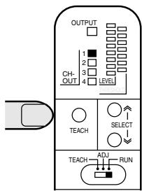
peration
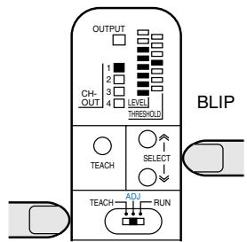
Detection is made in the RUN mode. The output ON/OFF status of each channel is displayed on the channel indicators. Double-displayed channels can be checked and selected by pressing the button.
For indicating detection level and threshold value for other channels
Press the SELECT button.
For checking which channel is indicated
Press the TEACH button
BLIP
Displays the channel the detection level of which is currently indicated in (CH-OUT). (For three seconds)
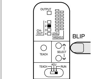
Displays the selected channel in (CHOUT) (for three seconds) and indicates the detection level and threshold value of the selected channel.
Registered Color Selection (Bank Selection Input)
1-output Models Only
In the RUN mode, bank selection can be made externally with the bank selection input 1 (yellow) and input 2 (green). The selected bank is indicated by the bank selection indicator.
NPN (E3MC-A11/-X11/-Y11)
| Bank | Input 1 | Input 2 |
| 1 | OPEN | OPEN |
| 2 | GND | OPEN |
| 3 | OPEN | GND |
| 4 | GND | GND |
PNP (E3MC-A41-/X41-/Y41)
| Bank | Input 1 | Input 2 |
| 1 | OPEN | OPEN |
| 2 | Vcc | OPEN |
| 3 | OPEN | Vcc |
| 4 | Vcc | Vcc |
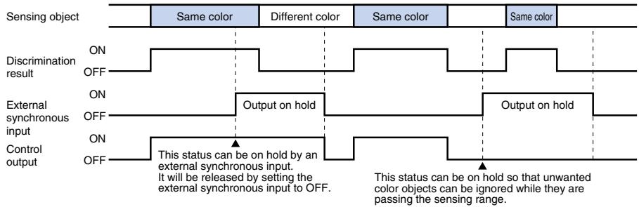
External synchronous input function
The measurement results will be directly output to the control output if the input from the external synchronous input terminal (pink) is set to OFF. The output will hold the previous status if the input of the external synchronous input terminal is set to ON. External synchronous input is valid in RUN or ADJ mode. As for the 4-output models, this function applies to the output of all the channels.
Remote teaching (remote control function)
Mode Setting
When using remote teaching (remote control function), you must set the Sensor to mode B.
Setting Method
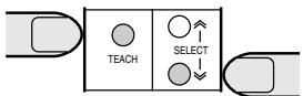
Apply power to the Sensor while pressing the SELECT DOWN button and TEACH button at the same time.
Checking Method
Whether the E3MC is operating in mode A or B can be checked with the operation indicator after mode setting (indicated for 3 s) or in the TEACH mode.
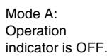
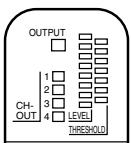
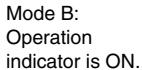
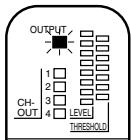
Note: 1 . The Sensor is set to mode A before shipment.
- The current mode selected does not change after the Sensor is turned OFF.
- The remote control function is available in the RUN mode or ADJ mode only.
- When mode B is selected, the E3MC-M□ has three outputs. In addition to this, the external synchronous input function is unusable.
- The same switching procedure can be used for changing to mode A.
Remote Teaching Method
1 Remote teaching with manual input through a mechanical switch
Short-circuit the remote control input for 1.5 s or more to either of the following terminals according to the E3MC model.
| NPN type (E3MC-□□11) | Connected to GND (blue) |
| PNP type (E3MC-□□41) | Short-circuit to Vcc (Brown) terminal. |
2 Remote control of teaching and bank selection through the PLC or PT
Input one of the following signals as a remote control input. Only when the signal is accepted properly, an answer-back output is provided for 0.3 s.
| No. | Control signal | E3MC-□ | E3MC-M□□ |
| 1 | ON OFF | 0.3s | Bank 1 selected. |
| 2 | ON OFF | 0.6s | Bank 2 selected. |
| 3 | ON OFF | 0.9s | Bank 3 selected. |
| 4 | ON OFF | 1.2s | Bank 4 selected. |
| 5 | ON OFF | 1.5s | To the selected bank Teaching |
The following is an example of ladder programming.
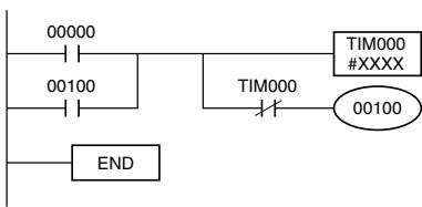
TIM000 set value
No.1:0003
No.2:0006
No.3:0009
No.4:00012
No 5:00015
http://www.cninfo.com.cn
Input: 00000 Output: 2010
Output:00100
Others:Work bits
The following is an example of a timing chart of teaching after bank selection.
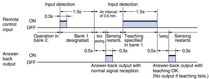
3
Remote control of threshold adjustments through the PLC or PT
Input one of the following signals as a remote control input. Only when the signal is accepted properly, the threshold is changed and an answer-back output is provided for 0.3 s.
| No. | Control signal | All E3MC models |
| 6 | ON OFF 0.3s 0.3s 0.3s 0.3s 0.3s 0.3s 0.3s 0.3s 0.3s 0.3s 0.3s 0.3s 0.3s 0.3s 0.3s 0.3s 0.3s 0.3s 0.3s 0.3s 0.3S 0.3S 0.3S 0.3S 0.3S 0.3S 0.3S 0.3S 0.3S 0.3S 0.3S 0.3S 0.3S 0.3S 0.3S 0.3S 0.3S 0.3S 0.3S 0.3S 0.3s 0.3s 0.3s 0.3s 0.3s 0.3s 0.3s 0.3s 0.3s 0.3s 0.3s 0.3s 0.3s 0.3s 0.3s 0.3s 0.3s 0.3s 0.3s 0.3r 0.3s 0.3s 0.3s 0.3s 0.3s 0.3s 0.3s 0.3s 0.3s 0.3s 0.3s 0.3s 0.3s 0.3s 0.3s 0.3s 0.3s 0.3s 0.3s 0.3R 0.3s 0.3s 0.3s 0.3s 0.3s 0.3s 0.3s 0.3s 0.3s 0.3s 0.3s 0.3s 0.3s 0.3s 0.3s 0.3s 0.3s 0.3s 0.3s 0.3 0.3s 0.3s 0.3s 0.3s 0.3s 0.3s 0.3s 0.3s 0.3s 0.3s 0.3s 0.3s 0.3s 0.3s 0.3s 0.3s 0.3s 0.3s 0.3s 0.3 s 0.3s 0.3s 0.3s 0.3s 0.3s 0.3s 0.3s 0.3s 0.3s 0.3s 0.3s 0.3s 0.3s 0.3s 0.3s 0.3s 0.3s 0.3s 0.3s 0.3 S 0.3s 0.3s 0.3s 0.3s 0.3s 0.3s 0.3s 0.3s 0.3s 0.3s 0.3s 0.3s 0.3s 0.3s 0.3s 0.3s 0.3s 0.3s 0.3s 0.3t 0.3s 0.3s 0.3s 0.3s 0.3s 0.3s 0.3s 0.3s 0.3s 0.3s 0.3s 0.3s 0.3s 0.3s 0.3s 0.3s 0.3s 0.3s 0.3s 0.38 0.3s 0.3s 0.3s 0.3s 0.3s 0.3s 0.3s 0.3s 0.3s 0.3s 0.3s 0.3s 0.3s 0.3s 0.3s 0.3s 0.3s 0.3s 0.3s 0.35 0.3s 0.3s 0.3s 0.3s 0.3s 0.3s 0.3s 0.3s 0.3s 0.3s 0.3s 0.3s 0.3s 0.3s 0.3s 0.3s 0.3s 0.3s 0.3s 0.3. 0.3s 0.3s 0.3s 0.3s 0.3s 0.3s 0.3s 0.3s 0.3s 0.3s 0.3s 0.3s 0.3s 0.3s 0.3s 0.3s 0.3s 0.3s 0.3s 0.3s | |
| 7 | ON OFF 0.3s 0.6s 0.3s Threshold 2 selected. | |
| 8 | ON OFF 0.3s 0.9s 0.3s Threshold 3 selected. | |
| 9 | ON OFF 0.3s 0.6s 0.6s Threshold 4 selected. | |
| 10 | ON OFF 0.3s 0.6s 0.6s Threshold 5 selected. | |
| 11 | ON OFF 0.3s 0.3s 0.9s Threshold 6 selected. | |
| 12 | ON OFF 0.6s 0.3s 0.3s Threshold 7 selected. |
Threshold level and indication

Tolerance 1
Tolerance 2
Tolerance 3
Tolerance 4
Tolerance 5
Tolerance 6
Tolerance 7
The following is an example of ladder programming for setting control signals. Full control of the E3MC is possible using this function together with function 2.
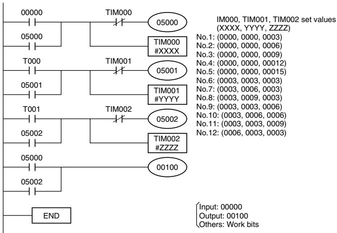
Note: 1 . The admissible error of each signal pulse is ± 0.1 s max.
2. A minimum interval of 0.6 s is required between signals.
3. Threshold 4 is set after teaching.
Analog output type
Setting Procedure for Setting the E3MC-MA81


Start detection after making setting in order of the above.
Calibration
This sensor has a calibration function that sets the output voltages of RGB to the same value using the standard white. For the A and X types, use the No. 4 terminal (yellow) to set the output values to 10 V. For the Y type, use the No. 1 terminal (white) to set them to 7 V.
① Set the standard white to the detection position.
(2) Input a 24V 1 ms or more signal to the calibration terminal.
③ It takes about 600 ms to make calibration.
④ Check the RGB outputs.
(5) Remove the standard white and start detection.
Precautions
- If the color used for calibration operation is other than white-based colors, the operation is canceled to return to the previous status since the outputs cannot be set to the same value.
- Note that if the No. 1 terminal (white) is used to perform the calibration operation of the A or X type, the output values are set to 7V and its capability cannot be exhibited fully.
- If the No. 4 terminal (yellow) is used to perform the calibration operation of the Y type, the operation will be insufficient since output compensation cannot be made. Therefore, always use the No. 1 terminal (white).
Correct Use
Common to E3MC series
Design
Power Reset Time
E3MC is ready to sense an object in 100 ms after power-on. Therefore, use the devices connected to E3MC 100 ms after power-on. If the load and E3MC are connected to different power supplies, always power on E3MC first. Especially for fine detection after power-on, warm up the system for about 15 minutes.
Power OFF
The E3MC may output a single pulse when the control power supply is turned OFF. If E3MC is connected to a timer or counter to which power is supplied from an independent power supply, E3MC will be more likely to output a single pulse when the control power supply is turned OFF. Therefore, supply power to the timer or counter from the same power supply for the E3MC.
Technical Guide
Detection of Metal or Glossy Objects
The color detection capability will be improved by changing the mounting angle of the Sensor so that regularly reflected light will not enter. The mounting angle of the E3MC-(M)X□□ can be adjusted about 10^ with its mounting holes.
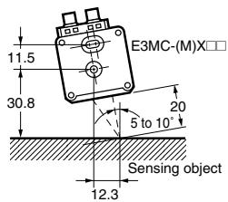
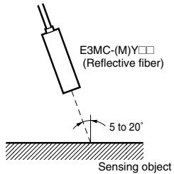
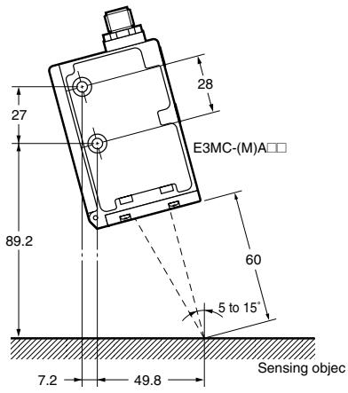
On the other hand, sensing objects such as metal or transparent plastic cases may be detected by allowing regular reflection.
Detection of White, Gray or Black Objects
When registering white, gray, black or other neutral-color objects, change the color discrimination mode to the Mode 1 mode to achieve a more stable intensity discrimination.
External Light
The E3MC may malfunction if it directly receives external light interference. Provide a cover to shut-out such external light interference.
Adjustment of Sensing Distance of General-purpose Optical Fiber Type
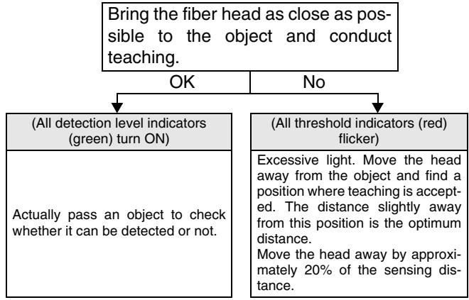
Unlike the E3MC-A or E3MC-X, the E3MC-Y may require adjustment of its sensing distance depending on the reflection rate. This also applies to the through-beam type.
DIN Track Mounting/Removal with the E39-L115
Mounting
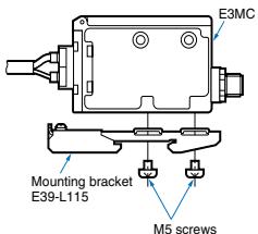
- Attach the E39-L115 Mounting Bracket to the E3MC with
four M5 screws.
- When mounting the E3MC to the DIN track, loosen the M3 screw of the Mounting Bracket and slide part A in the direction indicated by arrow ①.
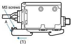
- Mount part (2) to the DIN track.
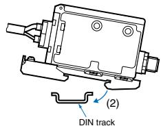
- Press the E3MC in the direction indicated by arrow ③ and slide part A in the direction indicated by arrow ④ until the Mounting Bracket correctly engages with the DIN track.
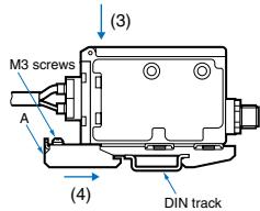
- Tighten the M3 screw of the Mounting Bracket to secure the Mounting Bracket.
(Dismantling)
Loosen the M3 screw of the E39-L115, press the E3MC in the direction indicated by arrow (5) and slide part A in the direction indicated by arrow (6). Then lift up the E3MC in the direction indicated by arrow (7) to remove the E3MC with the E39-L115.

Others EEPROM Error
If a write error occurs (the buzzer beeps and the operation indicator and bank indicator flicker) due to power-off, static electricity or other noise during write to EEPROM, perform teaching or threshold level setting again.
Protective Cover
Tighten the operation cover to a torque of 0.2 to 0.3Nm to ensure proper waterproofing.
Built-in Amplifier Type installation
Tightening Force
For case installation, tighten it to the torque of 2.3Nm max.
Sensor installation
This Sensor does not have the mutual interference prevention. When performing precision detection, use the Sensor with a cover for protection against disturbance light to ensure that the beams of incandescent and fluorescent lamps do not enter the fiber head and lens surface directly.
Optical Fiber Type
Installation
Tightening Force
For head installation, tighten it to the torque of 0.54Nm max.
Handling the Fiber Unit
- Do not pull or press the Fiber Unit.
- The bending radius of the fiber should be not less than the admissible bending radius given in Ratings/performance.
- Do not bend the fiber within 20mm from the head or amplifier coupling portion.
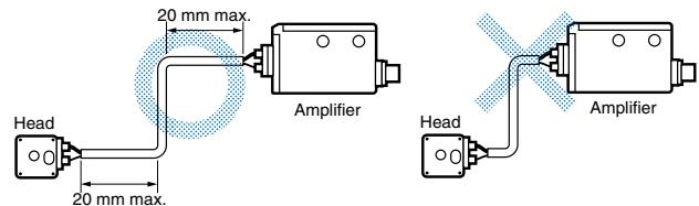
- Do not give compression or load.
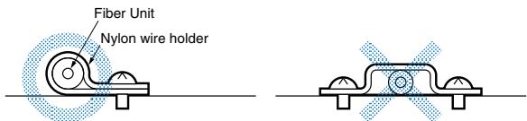
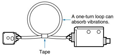
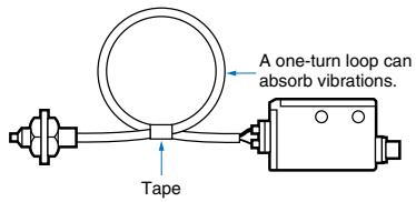
- The Fiber Head could be break by excessive vibration. To prevent this, the following is effective:
General-purpose Optical Fiber Type
Design
Definition of Sensing Distance of a Reflective Fiber
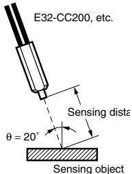
- The sensing distance of reflective fiber is the sensing distance of the Sensor located obliquely to the sensing object as shown in the following illustration.
- Set to C mode and standard mode (response time), and threshold set to the standard level with an inclination angle of 20 degrees E32-CC200.etc.
Recommended Fiber: Reflective Optical Fiber
The following optical fibers are recommended for use with the E3MC-(M)Y□□.
| Model | Sensing distance*1 |
| E32-DC200 | 5 mm |
| E32-CC200*2 | 5 mm |
| E32-D32L*3 | 4.5 mm |
| E32-D11L | 5 mm |
1. Distance where 11 colors of standard sensing objects can be discriminated. As a typical example, 9 colors can be discriminated when 12 mm is set.
2. The fiber to be inserted into the emitter is indicated with white lines. Insert the amplifier fiber into the lower emitter section.
*3. The fiber to be inserted into the emitter is indicated with dotted yellow lines. Insert the amplifier fiber into the lower emitter section.
Recommended Fiber: Through-beam Fiber
The following optical fibers are recommended for use with the E3MC-(M)Y□□.
| Model | Sensing distance |
| E32-TC200 | 30 mm |
| E32-T11L | 60 mm |
| E32-T16 | 200 mm |
| E32-T17L | 1.1 m |
- Distance where red, yellow and blue films can be discriminated stable.
Mounting
Insertion
The inserted Fiber Unit comes in contact with the internal rubber packing first. Insert the Fiber Unit further unit it comes in contact with the innermost end.
Sensor installation
Tighten the Fiber Unit with a screwdriver to a torque of 0.2Nm
Fibers
Among the recommended fibers, the E32-CC200 and E32-D32L have white or dotted yellow lines on the fiber to be inserted into the emitter. When using the E3MC-(M)Y□□, insert the fiber with the line into the emitter section at the bottom of the amp.
Common to Fiber Units
Mounting
Tightening Force
- The tightening force applied to the Fiber Unit should be as follows:
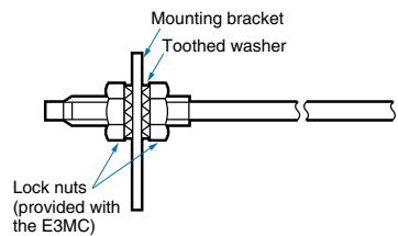
(Screwed type)
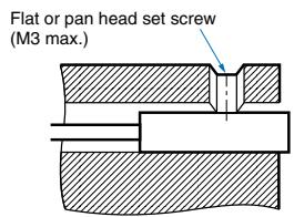
(Column ar type)
| Fiber Units | Clamping torque |
| M3/M4 screw | 0.78 Nm max. |
| M6 screw | 0.98 Nm max. |
| 2-dia. column | 0.29 Nm max. |
| 3-dia. column | 0.29 Nm max. |
| E32-T16 | 0.49 Nm max. |
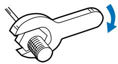
- Use a proper-sized wrench.
Cutting Fiber
- Insert a fiber into the Fiber Cutter and determine the length of the fiber to be cut.
- Press down the Fiber Cutter in a single stroke to cut the fiber.
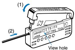
- The cutting holes cannot be used twice. If the same hole is used twice, the cutting face of the fiber will be rough and the sensing distance will be reduced. Always use an unused hole.
Connection
- Do not pull the Fiber Unit with force exceeding 9.8N or press the Fiber Unit with force exceeding 29.4N . The fiber is so thin that the utmost attention will be required to handle the fiber.
- Do not bend the end of the Fiber Unit.
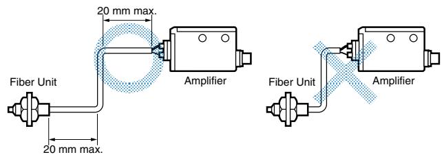
- Do not apply excess force on the Fiber Units.
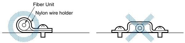
- The Fiber Head could break by excessive vibration. To prevent this, the following is effective:
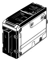
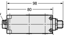
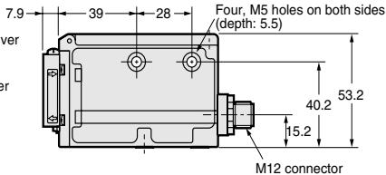
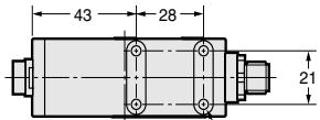
Sensors
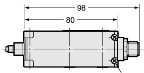
E3MC-A□□
E3MC-MA
E3MC-A81
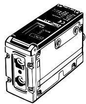
E3MC-A11
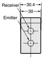
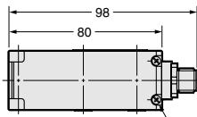
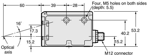
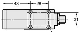
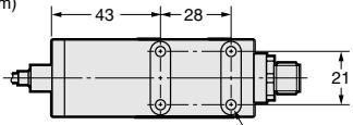
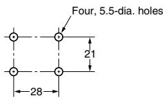
Four, M5 holes (depth: 5.5)
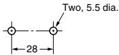
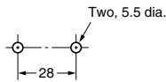
Mounting Dimensions Side Mounting
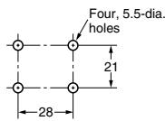
Bottom Mounting
E3MC-X□
E3MC-MX
E3MC-X81
E3MC-X11
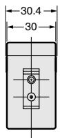
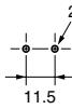
Mounting Dimensions (Fiber Head)
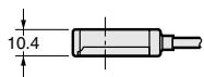
Two,M2.6 6

Four, M5 holes
(depth: 5.5)
Mounting Dimensions
(Amplifier Unit)
Bottom Mounting
E3MC-Y□□
E3MC-MY
E3MC-Y81
E3MC-Y11
Fiber Unit mounting screw
Four, M5 holes (depth: 5.5)
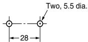
Mounting Dimensions Side Mounting
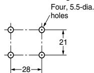
Bottom Mounting
Fiber Units
Accessories (Order Separately)
Sensor I/O Connectors
E39-C1 2M (included)
E39-C1 5M
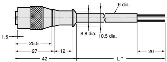
* E39-C1 2M: 2 m
E39-C1 5M:5m
- Attached to the product.
Mounting Brackets
H-5
ALL DIMENSIONS SHOWN ARE IN MILLIMETERS.
To convert millimeters into inches, multiply by 0.03937. To convert grams into ounces, multiply by 0.03527.
Cat. No. E256-E2-04A-X
In the interest of product improvement, specifications are subject to change without notice.
- Color sensor (LED type)
- E3MC
- Features
- Double Indication ensuring high visibility.
- Stable and Powerful Detection for Inline Use
- Long-distance Sensing with Built-in Amplifier Type
- Highly Resistant to Changes in Sensing Object Brightness and Ambient Temperature.
- Maintenance-free LED Light Source
- Principle of Detection
- Application
- Excellent Protective Structure and Maintenance Performance
- Discriminating Delicate Color Differences
- Conversion of Color Data into RGB Analog Data
- Timing chart
- ON/OFF type
- Setting Procedure
- Registered Color Selection (Bank Selection Input)
- 1-output Models Only
- External synchronous input function
- Remote teaching (remote control function)
- Mode Setting
- Setting Method
- Checking Method
- Remote Teaching Method
- Analog output type
- Calibration
- Precautions
- Correct Use
- Common to E3MC series
- Power Reset Time
- Power OFF
- Technical Guide
- DIN Track Mounting/Removal with the E39-L115
- Mounting
- (Dismantling)
- Others EEPROM Error
- Protective Cover
- Built-in Amplifier Type installation
- Tightening Force
- Sensor installation
- Optical Fiber Type
- Handling the Fiber Unit
- General-purpose Optical Fiber Type
- Design
- Definition of Sensing Distance of a Reflective Fiber
- Recommended Fiber: Reflective Optical Fiber
- Recommended Fiber: Through-beam Fiber
- Insertion
- Fibers
- Common to Fiber Units
- Cutting Fiber
- Connection
- Sensors
- Accessories (Order Separately)
Brand : OMRON
Model : E3MC
Category : Proximity Sensors