
E2K-L - Proximity sensor OMRON - Free user manual and instructions
Find the device manual for free E2K-L OMRON in PDF.


| Product Type | Capacitive proximity sensor for liquid level detection |
| Model | E2K-L13MC1 (8-11 mm) / E2K-L26MC1 (12-26 mm) |
| Applicable pipe diameter | E2K-L13MC1: 8 to 11 mm; E2K-L26MC1: 12 to 26 mm |
| Pipe material | Non-metallic |
| Max. wall thickness | E2K-L13MC1: 1 mm; E2K-L26MC1: 1.5 mm |
| Detected object | Liquid |
| Repeat accuracy | ±0.2 mm max. |
| Power supply | 12 to 24 VDC (10.8 to 30 VDC), max. ripple 10% |
| Current consumption | 12 mA max. |
| Output | NPN open collector, 100 mA max., residual voltage 1 V max. |
| Operation indicator | Orange LED |
| Ambient temperature | Operating: 0 to 55 °C; Storage: -10 to 65 °C |
| Ambient humidity | 25% to 85% (non-condensing) |
| Protection | IP66 (IEC 60529) |
| Connection | Pre-wired 2 m cable, 3 conductors (0.14 mm² cross section) |
| Weight | Approx. 70 g (packed) |
| Housing material | Heat-resistant ABS resin |
| Supplied accessories | 2 mounting clamps, 4 anti-slip tubes, instruction manual |
| Main functions | Contactless liquid level detection in non-metallic pipes |
| Maintenance and cleaning | Clean with a dry soft cloth; avoid solvents |
| Safety | Observe minimum distances from conductive objects; do not use in direct contact with liquids |
| Spare parts and repairability | No spare parts available; in case of failure, replace the device |
| General information | Capacitive sensor with built-in amplifier; 12-step sensitivity adjustment; pipe mounting with clamps |
Frequently Asked Questions - E2K-L OMRON
User questions about E2K-L OMRON
0 question about this device. Answer the ones you know or ask your own.
Ask a new question about this device
Download the instructions for your Proximity sensor in PDF format for free! Find your manual E2K-L - OMRON and take your electronic device back in hand. On this page are published all the documents necessary for the use of your device. E2K-L by OMRON.
USER MANUAL E2K-L OMRON
- Installation on pipes.
- Sensing by means electrostatic capacity and is not influenced by the color of the pipe or liquid.
• Available in 8 to 11 mm dia. and 12 to 26 mm dia. models to enable sensing for a wide range of pipe diameters.
• Built-in amplifier for space-saving.
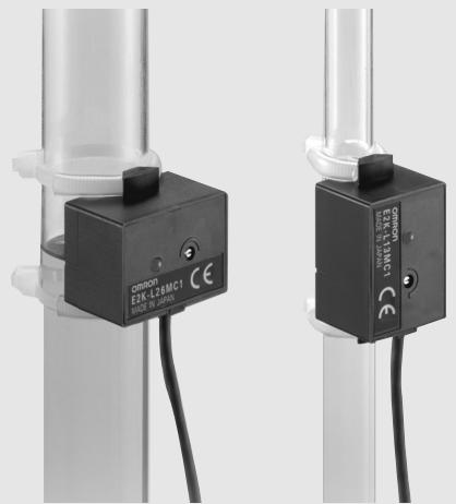
natural_image
Close-up of two black industrial sensor modules mounted on cylindrical stands, no visible text or symbolsCE
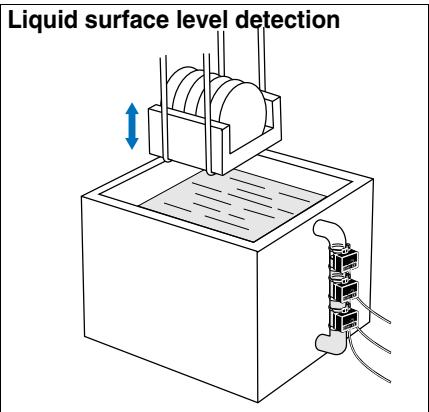
Applications
Ordering Information
| Sensor type | Applicable pipe diameters | Shape | Output form | Model | ||
| Electrostatic capacity method | 8 to 11 mm dia. |  | NPN open-collector output | NO | E2K-L13MC1 | |
| 12 to 26 mm dia. |  | E2K-L26MC1 | ||||
Rating/Performance
| Item Model | E2K-L13MC1 | E2K-L26MC1 | ||
| Applicable pipes | Material | Non-metal | ||
| Size | External diameter | 8 to 11 mm dia. | 12 to 26 mm dia. | |
| Wall thickness | 1 mm max. | 1.5 mm max. | ||
| Sensing object | Liquid (see note) | |||
| Repetition precision | ±0.2 mm max. | |||
| Response difference (reference value only; varies with pipe size and solution) | 0.6 to 5 mm | 0.3 to 3 mm | ||
| Supply voltage (operating voltage range) | 12 to 24 VDC, 10% max. ripple (10.8 to 30 VDC) | |||
| Current consumption | 12 mA max. | |||
| Control output | Switching capacity | 100 mA max. | ||
| Residual voltage | 1 V max. (under load current of 100 mA with cable length of 2 m) | |||
| Detection position of liquid surface | Notch position (For details, refer to Sensitivity Adjustment on next page.) | |||
| Indicator lamp | Operation indicator (orange) | |||
| Ambient temperature | Operating: 0 to 55°C; Storage: -10 to 65°C (with no icing or condensation) | |||
| Ambient humidity | Operating/storage: 25% to 85% (with no condensation) | |||
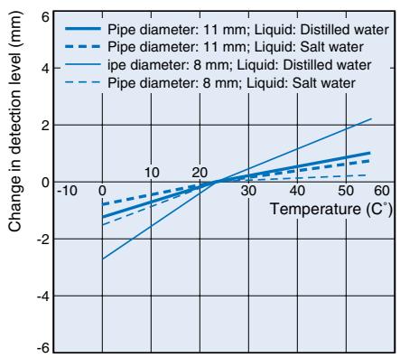
| Temperature influence | In the range 0 to 55°C: Detection level at 23°C 4 mm (with distilled water or 20 % salt water concentration)(±6 mm with E2K-L13MC1 for distilled water in pipe of 8 mm diameter) | |||
| Voltage influence | At the rated power supply voltage ±10%: Detection level at rated supply voltage ±0.5 mm | |||
| Insulation resistance | 50 M min. (at 500 VDC) between energized parts and case | |||
| Dielectric strength | 500 VAC 50/60 Hz for 1 min between energized part and case | |||
| Vibration resistance | 10 to 55 Hz, 1.5 mm double amplitude for 2 hours each in X, Y, and Z directions | |||
| Shock resistance | 500 m/s2 for 3 times each in X, Y, and Z directions | |||
| Protective structure | IEC 60529 IP66 | |||
| Connection method | Pre-wired models (standard length: 2 m) | |||
| Weight (Packed state) | Approx. 70 g | |||
| Material | Case, cover | Heat-resistant ABS resin | ||
| Cable clamp | NBR | |||
| Accessories | 2 binding bands, 4 nonskid tubes, instruction manual | |||
Note: In the following cases, stable detection may not be possible and ensure to confirm correct operation in the actual installation before use.
1. If the dielectric constant or conductivity of the liquid is low.
2. If the capacity of the liquid is small, or if the pipe diameter is so small or the pipe walls are so thick that the amount by which the capacity changes relating to the liquid level is small.
3. In case of an increased gassing or a highly viscous liquid firm residue on the inside walls of the pipe, or a dirt clogging on the inner or outer walls of the pipe.
Characteristic data (typical)
Influence of Temperature on Detection Level
E2K-L13MC1
line
| Temperature (C°) | Pipe diameter: 11 mm; Liquid: Distilled water | Pipe diameter: 11 mm; Liquid: Salt water | ipe diameter: 8 mm; Liquid: Distilled water | Pipe diameter: 8 mm; Liquid: Salt water | | ---------------- | --------------------------------------------- | ----------------------------------------- | ------------------------------------------- | ---------------------------------------- | | -10 | -3.0 | -2.0 | -2.5 | -2.0 | | 0 | -1.0 | -0.5 | -0.5 | -0.5 | | 10 | 0.0 | 0.0 | 0.0 | 0.0 | | 20 | 1.0 | 0.5 | 0.5 | 0.5 | | 30 | 2.0 | 1.0 | 1.0 | 1.0 | | 40 | 3.0 | 1.5 | 1.5 | 1.5 | | 50 | 4.0 | 2.0 | 2.0 | 2.0 | | 60 | 5.0 | 2.5 | 2.5 | 2.5 |E2K-L26MC1
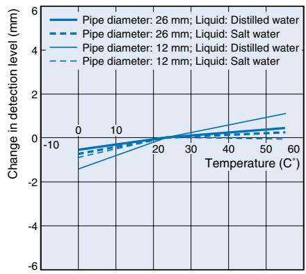
line
| Temperature (C*) | Pipe diameter: 26 mm; Liquid: Distilled water | Pipe diameter: 26 mm; Liquid: Salt water | Pipe diameter: 12 mm; Liquid: Distilled water | Pipe diameter: 12 mm; Liquid: Salt water | | ---------------- | --------------------------------------------- | ----------------------------------------- | --------------------------------------------- | ----------------------------------------- | | 0 | -1.0 | -1.0 | -1.5 | -1.5 | | 10 | -0.5 | -0.5 | -0.8 | -0.8 | | 20 | 0.0 | 0.0 | -0.2 | -0.2 | | 30 | 0.5 | 0.5 | 0.2 | 0.2 | | 40 | 1.0 | 1.0 | 0.5 | 0.5 | | 50 | 1.5 | 1.5 | 0.8 | 0.8 | | 60 | 2.0 | 2.0 | 1.0 | 1.0 |Output Circuit Diagram
| Output form | Model | Timing chart | Output circuit | |
| NO | E2K-L13MC1E2K-L26MC1 | Liquid surfaceLoad(brown-black)Operation indicator(orange) | YesNoOperatesReleasesONOFF | 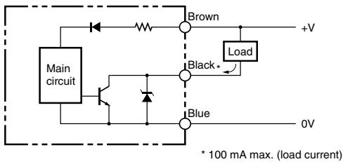 |
Operation
Sensitivity adjustment
- Install the Sensor with the setting position (notch) in line with the liquid level to be detected.
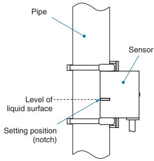
- After Sensor installation adjust the detecting sensitivity using the (12-step) sensitivity adjuster in the way shown below.
| Status of the indicator when the liquid level is aligned with the setting position | Sensitivity adjuster | Adjustment procedure |
| Not lit | 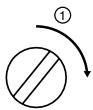 | Turn the sensitivity adjuster clockwise using a screwdriver until the indicator lights. |
| Lit | 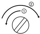 | Turn the sensitivity adjuster counterclockwise using a screwdriver until the indicator turns OFF. Then, turn the sensitivity adjuster clockwise until the indicator lights up again. |
Note: 1. During sensitivity adjustment do not put your hand on the Sensor and make sure that the cable is properly secured. Failure to observe these points may affect the detection level.
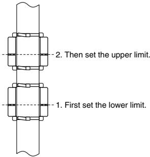
2. When using more than one Sensor (e.g., to detect for upper and lower limits), adjust the sensitivity of the Sensors in order starting from the bottom. Adjusting the sensitivity of a Sensor may affect the detection level of the Sensor above it.
Correct Use
Design
Influence of Surrounding Objects
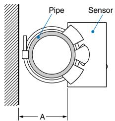
Performance may be adversely affected by conductive objects (e.g., metals) in the vicinity of the Sensor. Ensure that any conductive objects are separated from the Sensor and set at a minimum distance as shown below.
Object on Opposite Side
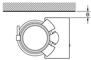
natural_image
Technical drawing of a mechanical assembly with a circular component and a rectangular housing (no text or symbols)Object on One Side
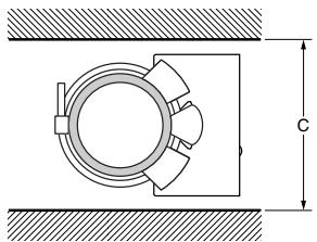
natural_image
Technical drawing of a mechanical assembly with concentric rings and a central shaft, shown with dimension lines (no text or symbols)Objects on Both Sides
Influence of Surrounding Objects (Units: mm)
| Shape Length | A | B | C |
| E2K-L13MC1 | 25 | 5 | 45 |
| E2K-L26MC1 | 0 | 40 |
Mutual Interference
When installing 2 or more Sensors in series, in parallel, or facing each other, be sure that they are separated by at least the distances shown below.
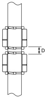
natural_image
Technical line drawing of a mechanical assembly with two stacked components and a dimension label D (no text or symbols present)Installed in Series Sides
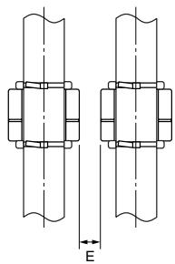
natural_image
Technical diagram of two mechanical fasteners with bolted joints and a vertical dimension line labeled E (no text or symbols beyond the label)Installed in Parallel
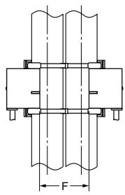
Installed in Facing Each Other
Mutual Interference
(Unit: mm)
| Shape Length | D (see note) | E | F |
| E2K-L13MC1 | 10 | 10 | 25 |
| E2K-L26MC1 | 30 |
* The detection level for the top Sensor may change when the detection level for the bottom Sensor is set. Be sure to set the detection level for the bottom Sensor first.
Installation
Sensor installation
Attach the Sensor securely to the pipe using the 2 binding bands and the 4 nonskid tubes provided (2 tubes per band) in the way shown below.
Install the Sensor in such manner that the pipe is in contact with the entire sensing face of the Sensor with the pipe and Sensor in parallel.
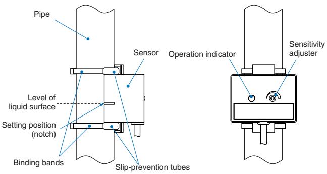
Side View
Front View
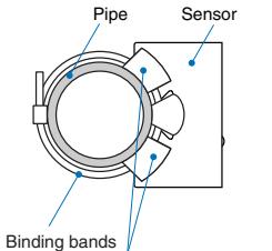
Slip-prevention tubes Top View
Wiring Considerations
Power Supply
- If separate power supplies are used for Sensor and load, be sure to turn on the Sensor power supply first.
- If a commercially available switching regulator is used, the Sensor may malfunction because of switching noise. Connect the frame ground and ground terminals to ground.
● Operating Environment
Ambient Conditions
- Although this product has waterproof specifications, do not use it in locations where it may have a direct contact with liquids (e.g., water or cutting oil). Such locations can interfere with the electrostatic capacity method used by the Sensor.
- Even if the Sensor is used within the specified temperature range, do not subject it to sudden changes in temperature because this will shorten the service life.
Miscellaneous
Drift may occur when the power supply is turned ON. If the dielectric constant of the liquid is low, the detection level of the liquid may be 2 to 3 mm higher than the set level for approximately 20 minutes after power is turned ON.
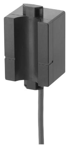
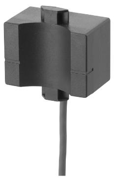
E2K-L13MC1
natural_image
Close-up of a black mechanical component with a vertical shaft and protruding shaft (no visible text or symbols)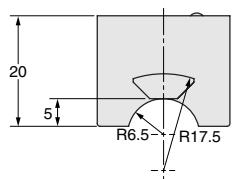
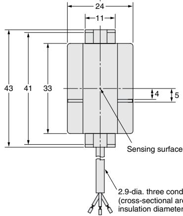
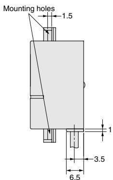
2.9-dia. three conductors vinyl-insulated round cable (cross-sectional area of conductors: 0.14 mm ^2 ; insulation diameter: 0.9 mm) Standard length: 2 m
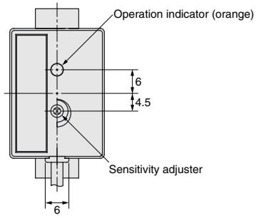
E2K-L26MC1
natural_image
Close-up of a black mechanical component with a vertical rod inserted (no visible text or symbols)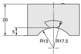
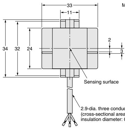
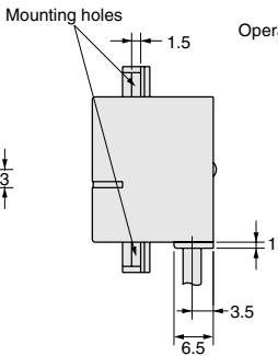
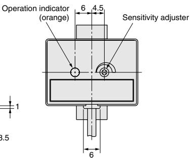
2.9-dia. three conductors vinyl-insulated round cable (cross-sectional area of conductors: 0.14 mm ^2 ; insulation diameter: 0.9 mm) Standard length: 2 m
ALL DIMENSIONS SHOWN ARE IN MILLIMETERS.
To convert millimeters into inches, multiply by 0.03937. To convert grams into ounces, multiply by 0.03527.
Cat. No. D094-E2-01-X
In the interest of product improvement, specifications are subject to change without notice.
- Applications
- Ordering Information
- Characteristic data (typical)
- Output Circuit Diagram
- Operation
- Sensitivity adjustment
- Correct Use
- Design
- Influence of Surrounding Objects
- Mutual Interference
- Installation
- Sensor installation
- Wiring Considerations
- Power Supply
- ● Operating Environment
- Ambient Conditions
- Miscellaneous
Brand : OMRON
Model : E2K-L
Category : Proximity sensor