
E2F-Y - Proximity Sensors OMRON - Free user manual and instructions
Find the device manual for free E2F-Y OMRON in PDF.


| Product Type | Inductive Proximity Sensor |
| Brand | OMRON |
| Model | E2F-Y |
| Housing Material | Polyarylate (plastic) |
| Detection Distance | 1.5 mm to 10 mm depending on model |
| Supply Voltage | 24 to 240 VAC (20 to 264 VAC) |
| Response Frequency | 25 Hz |
| Output Type | 2-wire AC, NO or NC depending on model |
| Load Current | 5 to 300 mA depending on model |
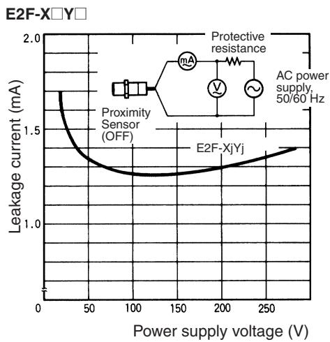
| Leakage Current | 1.7 mA max. at 200 VAC |
| Operation Indicator | Red LED (lit when object is detected) |
| Ambient Temperature | -25 °C to 70 °C (no icing or condensation) |
| Ambient Humidity | 35% to 95% RH |
| Protection Rating | IP68 (according to OMRON test method) |
| Vibration Resistance | 10 to 55 Hz, double amplitude 1.5 mm, 2 h each axis |
| Shock Resistance | 1000 m/s² (destruction), 10 times each axis |
| Connection | Pre-wired, standard length 2 m |
| Weight (packed) | Approx. 40 to 170 g depending on model |
| Dimensions | Diameter 8 mm to 30 mm depending on model |
| Maintenance | Clean with a dry cloth; avoid aggressive solvents |
| Safety | Do not use for personal safety; respect tightening torques |
| Spare Parts | Not available separately |
| Repairability | Not user-repairable; replace entire unit |
Frequently Asked Questions - E2F-Y OMRON
User questions about E2F-Y OMRON
0 question about this device. Answer the ones you know or ask your own.
Ask a new question about this device
Download the instructions for your Proximity Sensors in PDF format for free! Find your manual E2F-Y - OMRON and take your electronic device back in hand. On this page are published all the documents necessary for the use of your device. E2F-Y by OMRON.
USER MANUAL E2F-Y OMRON
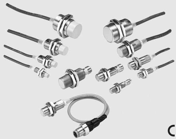
Cylindrical Inductive Sensor for AC Power Supply
E2E- □Y/E2F- □Y
24 to 240 VAC power supply voltage
- brass or plastic housing
(M8 in SUS housing)
C E
Ordering Information
Plastic Housing
AC 2-wire/Pre-wired Models
| Size | Sensing distance | Model | ||
| Operating status | ||||
| NO | NC | |||
| Shielded | M8 | 1.5 mm | E2F-X1R5Y1*1 | E2F-X1R5Y2*1 |
| M12 | 2 mm | E2F-X1Y1*1 | E2F-X2Y2*1 | |
| M18 | 5 mm | E2F-X5Y1*1*2 | E2F-X5Y2*1*2 | |
| M30 | 10 mm | E2F-X10Y1*1*2 | E2F-X10Y2*1*2 | |
1. A different frequency type is available (E2F-X□□5; e.g. E2F-X5E15)
2. A short-circuit protection type is available (E2F-X□Y□-53;
e.g. E2F-X5Y1-53) Power Supply Voltage: 100 to 120 VAC
Metal Housing
AC 2-wire/Pre-wired Models
| Size | Sensing distance | Operation mode | Model | |
| Shielded | M8 | 1.5 mm | NO | E2E-X1R5Y1 |
| NC | E2E-X1R5Y2 | |||
| M12 | 2 mm | NO | E2E-X2Y1*1*2 | |
| NC | E2E-X2Y2 | |||
| M18 | 5 mm | NO | E2E-X5Y1*1*2 | |
| NC | E2E-X5Y2 | |||
| M30 | 10 mm | NO | E2E-X10Y1*1*2 | |
| NC | E2E-X10Y2 | |||
| Un-shielded | M8 | 2 mm | NO | E2E-X2MY1 |
| NC | E2E-X2MY2 | |||
| M12 | 5 mm | NO | E2E-X5MY1*1*2 | |
| NC | E2E-X5MY2 | |||
| M18 | 10 mm | NO | E2E-X10MY1*1 | |
| NC | E2E-X10MY2 | |||
| M30 | 18 mm | NO | E2E-X18MY1*1 | |
| NC | E2E-X18MY2 | |||
1. Models with a different frequency are also available. These models are E2E-X□Y□5 (e.g., E2E-X5Y15).
2. Cables with a length of 5 m are also available. Specify the cable length at the end of the model number (e.g., E2E-X2Y1 5M).
AC 2-wire/Connector Models
| Size | Sensing distance | Operation mode | Model | |
| Shielded | M12 | 2 mm | NO | E2E-X2Y1-M1 |
| NC | E2E-X2Y2-M1 | |||
| M18 | 5 mm | NO | E2E-X5Y1-M1 | |
| NC | E2E-X5Y2-M1 | |||
| M30 | 10 mm | NO | E2E-X10Y1-M1 | |
| NC | E2E-X10Y2-M1 | |||
| Un-shielded | M12 | 5 mm | NO | E2E-X5MY1-M1 |
| NC | E2E-X5MY2-M1 | |||
| M18 | 10 mm | NO | E2E-X10MY1-M1 | |
| NC | E2E-X10MY2-M1 | |||
| M30 | 18 mm | NO | E2E-X18MY1-M1 | |
| NC | E2E-X18MY2-M1 | |||
Specifications
Plastic Housing (E2F)
| Model | E2F-X1R5Y□ | E2F-X2Y□ | E2F-X5Y□ | E2F-X10Y□ | |
| Sensing distance | 1.5 mm ±10% | 2 mm ±10% | 5 mm ±10% | 10 mm ±10% | |
| Setting distance | 0 to 1.2 mm | 0 to 1.6 mm | 0 to 4 mm | 0 to 8 mm | |
| Differential distance | 10% max | ||||
| Sensing object | Ferrous metal (Sensitivity lowers with non-ferrous metals) | ||||
| Standard sensing object | Iron, 8 x 8 x 1 mm | Iron, 12 x 12 x 1 mm | Iron, 18 x 18 x 1 mm | Iron, 30 x 30 x 1 mm | |
| Response frequency *1 | 25 Hz | ||||
| Power supply (Operating voltage range) | 24 to 240 VAC (20 to 264 VAC) | ||||
| Leakage current | 1.7 mA at 200 VAC | ||||
| Control output | Switching capacity | 5 to 100 mA | 5 to 300 mA | ||
| Residual voltage | Refer to the Specifications | ||||
| Indicator lamp | Operation indicator (red LED) | ||||
| Operation status (with sensing object approaching) | Y1 Models: ON Y2 Models: NC | ||||
| Protection circuit | None *2 | ||||
| Ambient temperature | Operating/Storage: -25 °C to 70 °C (with no icing or condensation) | ||||
| Ambient humidity | Operating/Storage: 35% to 95% RH | ||||
| Temperature influence | A maximim fluctuation of ±10% max. of sensing distance at 23 °C in the temperature range of -25 °C to 70 °C | ||||
| Voltage influence | ±1% max. of sensing distance within a range of ±10% of rated power supply voltage | ||||
| Insulation resistance | 50 MΩ min. (at 500 VDC) between current carry parts and case | ||||
| Vibration resistance | 10 to 55 Hz, 1.5 mm double amplitude for 2 hours each in X, Y, and Z directions | ||||
| Shock resistance | Destruction: 1,000 m/s² for 10 times each in X, Y, and Z directions | ||||
| Protective structure | IEC IP68 *3 | ||||
| Connection method | Pre-wired models (standard length 2 m) | ||||
| Weight (Packed state) | Approx. 40 g | Approx. 50 g | Approx. 130 g | Approx. 170 g | |
| Material | Case | Polyarylate | |||
| Sensing surface | |||||
| Clamping nut | Polyarylate resin | ||||
| Accessories | Instruction manual | ||||
1. The response frequencies are average values measured on condition that the distance between each sensing object is twice as large as the size of the sensing object and the sensing distance set is half of the maximum sensing distance.
2. Short circuit protection types are available.
*3. OMRON test method
Conditions: Less than 10m natural state under water
(1) It is not flooded underwater with two atmospheric pressure for 1 hour.
(2) A heat shock cycle (it is 1 hour, respectively to 0^ cold water and 70^ warm water) is repeated 20 times, and the performance of detection distance and insulation resistance is checked.
Metal Housing (E2E)
| Size | M8 | M12 | M18 | M30 | |||||
| Type | Shielded | Unshielded | Shielded | Unshielded | Shielded | Unshielded | Shielded | Unshielded | |
| Item | E2E-X1R5Y□ | E2E-X2MY□ | E2E-X2Y□ | E2E-X5MY□ | E2E-X5Y□ | E2E-X10MY□ | E2E-X10Y□ | E2E-X18MY□ | |
| Sensing distance | 1.5 mm ±10% | 2 mm ±10% | 2 mm ±10% | 5 mm ±10% | 5 mm ±10% | 10 mm ±10% | 10 mm ±10% | 18 mm ±10% | |
| Set distance | 0 to 1.2 mm | 0 to 1.6 mm | 0 to 1.6 mm | 0 to 4.0 mm | 0 to 4.0 mm | 0 to 8.0 mm | 0 to 8.0 mm | 0 to 14.0 mm | |
| Differential travel | 10% max. of sensing distance | ||||||||
| Sensing object | Ferrous metal (The sensing distance decreases with non-ferrous metal, refer to Engineering Data.) | ||||||||
| Standard sensing object | Iron, 8 x 8 x 1 mm | Iron,12 x 12 x 1 mm | Iron, 12 x 12 x 1 mm | Iron, 15 x 15 x 1 mm | Iron, 18 x 18 x 1 mm | Iron, 30 x 30 x 1 mm | Iron, 30 x 30 x 1 mm | Iron, 54 x 54 x 1 mm | |
| Response speed | 25 Hz | ||||||||
| Power supply voltage (operating voltage range) *1 | 24 to 240 VAC, 50/60 Hz (20 to 264 VAC) | ||||||||
| Leakage current | 1.7 mA max. | ||||||||
| Control output | Load current *2 | 5 to 100 mA | 5 to 200 mA | 5 to 300 mA | |||||
| Residual voltage | Refer to Engineering Data. | ||||||||
| Indicator | Operation indicator (red LED) | ||||||||
| Operation mode (with sensing object approaching) | Y1 Models: NO Y2 Models: NC For details, refer to Timing Charts. | ||||||||
| Protection circuit | Surge suppressor | ||||||||
| Ambient temperature *1 *2 | Operating/Storage: -25 °C to 70 °C (with no icing or condensation) | Operating/Storage: -40 °C to 85 °C (with no icing or condensation) | |||||||
| Ambient humidity | Operating/Storage: 35% to 95% (with no condensation) | ||||||||
| Temperature influence | ±10% max. of sensing distance at 23 °C in the temperature range of -25 °C to 70 °C | ±15% max. of sensing distance at 23 °C in the temperature range of -40 °C to 85 °C ±10% max. of sensing distance at 23 °C in the temperature range of -25 °C to 70 °C | |||||||
| Voltage influence | ±1% max. of sensing distance in the rated voltage range ±15% | ||||||||
| Insulation resistance | 50 MΩ min. (at 500 VDC) between current-carrying parts and case | ||||||||
| Dielectric strength | 4,000 VAC at 50/60 Hz for 1 min between current-carrying parts and case (2,000 VAC for M8 Models) | ||||||||
| Vibration resistance | 10 to 55 Hz, 1.5-mm double amplitude for 2 hours each in X, Y, and Z directions | ||||||||
| Shock resistance | 500 m/s² 10 times each in X, Y, and Z directions | 1,000 m/s² 10 times each in X, Y, and Z directions | |||||||
| Degree of protection | IEC 60529 IP67 (Pre-wired models: JEM standard IP67g (waterproof, oil-proof)) | ||||||||
| Connection method | Pre-wired models (standard length 2 m), connector models | ||||||||
| Weight (packed state) | Pre-wired models | Approx. 60 g | Approx. 70 g | Approx. 130 g | Approx. 175 g | ||||
| Connector models | Approx. 15 g | Approx. 25 g | Approx. 40 g | Approx. 90 g | |||||
| Material | Case | Stainless steel (SUS303) | Brass-nickel plated | ||||||
| Sensing surface | PBT (polybutylene terephthalate) | ||||||||
| Clamping nuts | Brass-nickel plated | ||||||||
| Toothed washer | Iron-zinc plated | ||||||||
| Accessories | Instruction manual | ||||||||
1. When supplying 24 VAC to any of the above models, make sure that the operating ambient temperature range is over -25^ .
2. When using an M18- or M30-sized E2E within an ambient temperature of 70^ C to 85^ C ,make sure that the E2E has a control output of 5 to 200 mA max.
Output Circuit and Timing Charts
| Output | Operating Status | Model | Timing chart | Output circuit | |
| AC 2-wire Models | NO | E2F-X1R5Y1 | Sensing object Yes | Main circuit | |
| E2F-X2Y1 | Load Operates | ||||
| E2F-X5Y1 | Releases | ||||
| E2F-X10Y1 | Detection indicator ON | ||||
| E2E-□Y1 | OFF | ||||
| NC | E2F-X1R5Y2 | Sensing object Yes | Blue | ||
| E2F-X2Y2 | Load Operates | ||||
| E2F-X5Y2 | Releases | ||||
| E2F-X10Y2 | Detection indicator ON | ||||
| E2E-□Y2 | OFF | ||||
Pin Arrangement
E2E-X□Y□-M1 AC 2-wire Models
| Operation mode | Applicable models | Pin arrangement |
| NO | E2E-X□Y1-M1 | Note: Terminals 1 and 2 are not used. |
| NC | E2E-X□Y2-M1 | Note: Terminals 3 and 4 are not used. |
E2E
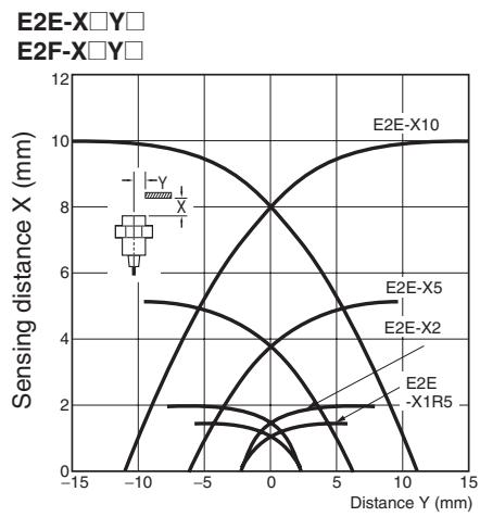
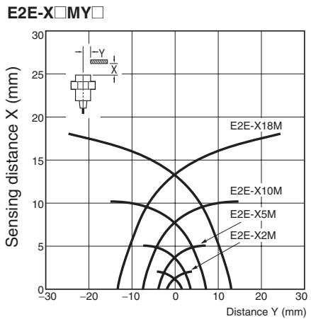
Operating Range (Typical)
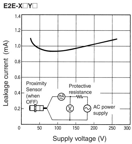
Leakage Current (Typical)
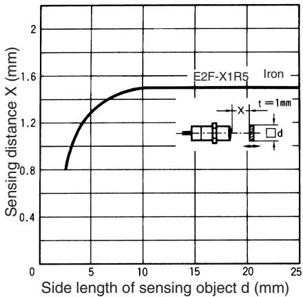
E2F Sensing Distance vs. Sensing Object
E2F-X1R5□□
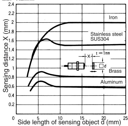
E2F-X2□□
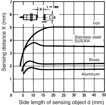
E2F-X5□□
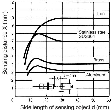
E2F-X10□□
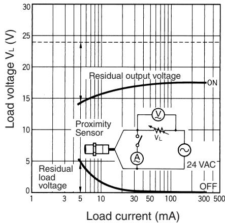
Residual Output Voltage (Typical)
E2E-X□Y□
24 VAC
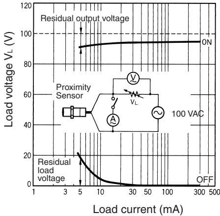
100 VAC
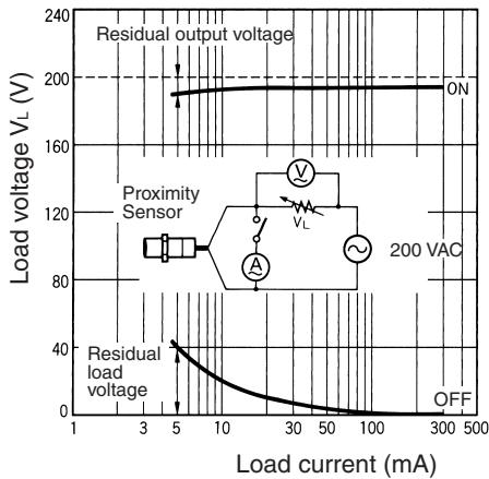
200 VAC

Sensing Distance vs. Sensing Object (Typical)
E2E-X1R5Y□
E2F-X1R5Y1
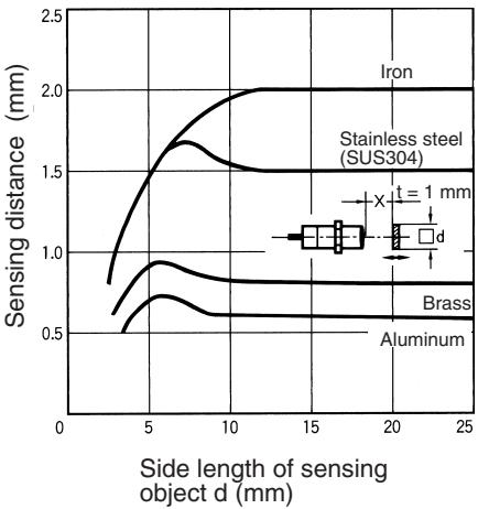
E2E-X2Y□
E2F-X2Y1
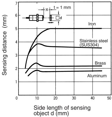
E2E-X5Y□
E2F-X5Y1
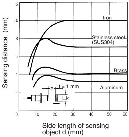
E2E-X10Y□
E2F-X10Y□
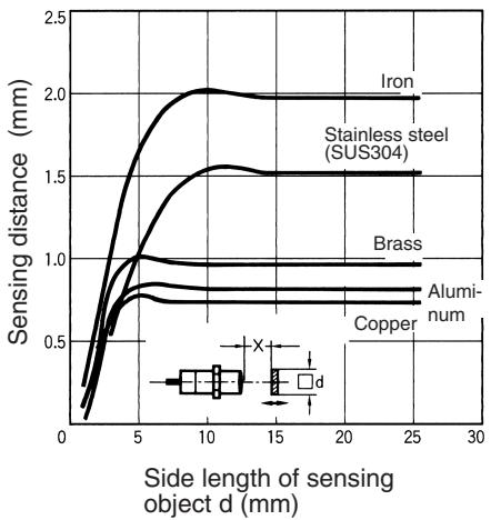
E2E-X2MY
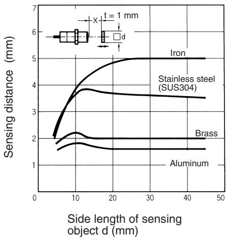
E2E-X5MY
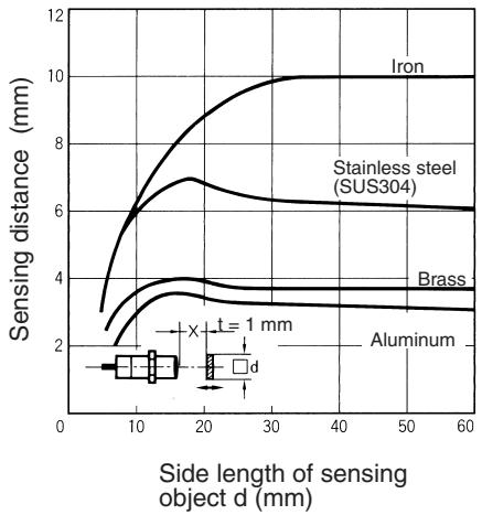
E2E-X10MY
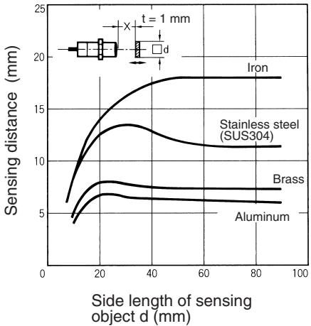
E2E-X18MY
Installation
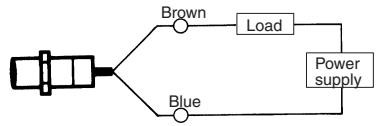
Connection
E2E-X□Y/ E2F-X□Y AC 2-wire Models
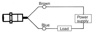
Note: The load can be connected as shown above.
Precautions
Mounting
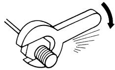
Do not tighten the nut with excessive force. A washer must be used with the nut.
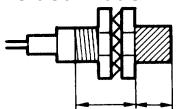
Shielded Model
Part B Part A
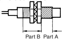
Unshielded Model
Note: The table below shows the tightening torques for part A and part B nuts. In the previous examples, the nut is on the sensor head side (part B) and hence the tightening torque for part B applies. If this nut is in part A, the tightening torque for part A applies instead.
| Model | Part A | Part B | ||
| Length | Torque | Torque | ||
| M8 | Shielded | 9 mm | 9 N·m | 12 N·m |
| Unshielded | 3 mm | |||
| M12 | 30 N·m | |||
| M18 | 70 N·m | |||
| M30 | 180 N·m | |||
Influence of Surrounding Metal
When mounting the E2E / E2F within a metal panel, ensure that the clearances given in the following table are maintained. Failure to maintain these distances may cause deterioration in the performance of the sensor.
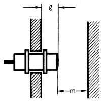
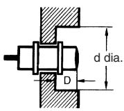
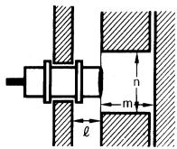
| Model | I | d | D | m | n | ||
| E2E-X☐Y☐AC 2-wire | Shielded | M8 | 0 mm | 8 mm | 0 mm | 4.5 mm | 12 mm |
| M12 | 0 mm | 12 mm | 0 mm | 8 mm | 18 mm | ||
| M18 | 0 mm | 18 mm | 0 mm | 20 mm | 27 mm | ||
| M30 | 0 mm | 30 mm | 0 mm | 40 mm | 45 mm | ||
| Un-shielded | M8 | 6 mm | 24 mm | 6 mm | 8 mm | 24 mm | |
| M12 | 15 mm | 40 mm | 15 mm | 20 mm | 36 mm | ||
| M18 | 22 mm | 55 mm | 22 mm | 40 mm | 54 mm | ||
| M30 | 30 mm | 90 mm | 30 mm | 70 mm | 90 mm | ||
| Model | I | d | D | m | n | |
| E2F-X1R5□□ | M8 | 0 mm | 8 mm | 0 mm | 4.5 mm | 12 mm |
| E2F-X25□□ | M12 | 0 mm | 12 mm | 0 mm | 8 mm | 18 mm |
| E2F-X5□□ | M18 | 0 mm | 18 mm | 0 mm | 20 mm | 27 mm |
| E2F-X10□□ | M30 | 0 mm | 30 mm | 0 mm | 40 mm | 45 mm |
Mutual Interference
When installing two or more Sensors face to face or side by side, ensure that the minimum distances given in the following table are maintained.
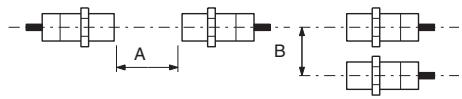
Unit: mm
| Model | Item | M8 | M12 | M18 | M30 | |
| E2E-X☐Y☐AC 2-wire | Shielded | A | 20 | 30 (20) | 50 (30) | 100 (50) |
| B | 15 | 20 (12) | 35 (18) | 70 (35) | ||
| Un-shielded | A | 80 | 120 (60) | 200 (100) | 300 (100) | |
| B | 60 | 100 (50) | 110 (60) | 200 (100) | ||
| E2F-X1R5☐☐ | A | 20 | - | - | - | |
| B | 1% | - | - | - | ||
| E2F-X25☐☐ | A | - | 30 (20) | - | - | |
| B | - | 20 (12) | - | - | ||
| E2F-X5☐☐ | A | - | - | 50 (30) | - | |
| B | - | - | 35 (18) | - | ||
| E2F-X10☐☐ | A | - | - | - | 100 (50) | |
| B | - | - | - | 70 (35) | ||
Note: Figures in the parentheses are for E2F used in combination with an E2F (i.e., E2F-X□□□5) that is operating at a different frequency.

WARNING
This product is not designed or rated for ensuring safety of persons.
Do not use it for such purposes.

Precautions for Safe Use
The colors in parentheses are previous wire colors.
| Item | Examples |
| Connection with no loadMake sure to connect a proper load to the E2E in operation, otherwise it may explode or burn. | Brown Sensor Blue Incorrect |
Precautions for Correct Use
Installation
Power Reset Time
The Proximity Sensor is ready to operate within 100 ms after power is supplied. If power supplies are connected to the Proximity Sensor and load respectively, be sure to supply power to the Proximity Sensor before supplying power to the load.
Power OFF
The Proximity Sensor may output a pulse signal when it is turned OFF. Therefore, it is recommended to turn OFF the load before turning OFF the Proximity Sensor.
Power Supply Transformer
When using a DC power supply, make sure that the DC power supply has an insulated transformer. Do not use a DC power supply with an auto-transformer.
Sensing Object
Metal Coating:
The sensing distances of the Proximity Sensor vary with the metal coating on sensing objects.
Wiring
High-tension Lines
Wiring through Metal Conduit
If there is a power or high-tension line near the cable of the Proximity Sensor, wire the cable through an independent metal conduit to prevent against Proximity Sensor damage or malfunctioning.
Cable Tractive Force
Do not pull on cables with tractive forces exceeding the following.
| Diameter | Tractive force |
| 4 dia. | 50 N max. |
Mounting
The Proximity Sensor must not be subjected to excessive shock with a hammer when it is installed, otherwise the Proximity Sensor may be damaged or lose its water-resistivity.
Environment
Water Resistivity
Do not use the Proximity Sensor underwater, outdoors, or in the rain.
Operating Environment
Be sure to use the Proximity Sensor within its operating ambient temperature range and do not use the Proximity Sensor outdoors so that its reliability and life expectancy can be maintained. Although the
Proximity Sensor is water resistive, a cover to protect the Proximity
Sensor from water or water soluble machining oil is recommended so that its reliability and life expectancy can be maintained.
Do not use the Proximity Sensor in an environment with chemical gas (e.g., strong alkaline or acid gasses including nitric, chromic, and concentrated sulfuric acid gases).
Connecting Load to AC 2-wire Sensor
Refer to the following before using AC 2-wire Proximity Sensors.
Surge Protection
Although the Proximity Sensor has a surge absorption circuit, if there is any machine that has a large surge current (e.g., a motor or welding machine) near the Proximity Sensor, connect a surge absorber to the machine.
Leakage Current
When the Proximity Sensor is OFF, the Proximity Sensor has leakage current. Refer to 5 and 6 Leakage Current Characteristics. In this case, the load is imposed with a small voltage and the load may not be reset. Before using the Proximity Sensor, make sure that this voltage is less than the load reset voltage. The AC 2-wire Proximity Sensor cannot be connected to any card-lift-off relay (e.g., the G2A) because contact vibration of the relay will be caused by the leakage current and the life of the relay will be shortened.
Countermeasures Against Leakage Current
AC 2-wire Models
Connect a bleeder resistor as the bypass for the leakage current so that the current flowing into the load will be less than the load reset current.
As shown in the following diagram, connect the bleeder resistor so that the current flowing into the Proximity Sensor will be 10mA minimum and the residual voltage imposed on the load will be less than the load reset voltage.
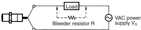
Refer to the following to calculate the bleeder resistance and the allowable power of the bleeder resistor.
R ≤ Vs/(10 - 1) (kΩ)
P > VS²/R (mW)
P:The allowable power of the bleeder resistor. (The actual power capacity of the bleeder resistor must be at least a few times as large as the allowable power of the bleeder resistor.)
I:Load current (mA)
The following resistors are recommended.
100 VAC (supply voltage): A resistor with a resistance of 10k maximum and an allowable power of 3 W minimum
200 VAC (supply voltage): A resistor with a resistance of 20k maximum and an allowable power of 10 W minimum
If these resistors generate excessive heat, use a resistor with a resistance of 10k maximum and an allowable power of 5 W minimum at 100 VAC and a resistor with a resistance of 20k maximum and an allowable power of 10 W minimum at 200 VAC instead.
Precautions for AC 2-wire Proximity Sensors in Operation Connection
| Model | Connection type | Method | Description |
| AC 2-wire | AND (series connection) | Incorrect Vs Correct X1 X2 Load X1 X2 Vs Vs Vs Vs Vs Vs Vs Vs Vs Vs Vs Vs Vs Vs Vs Vs Vs Vs Vs Vs Vs Vs Vs Vs Vs Vs Vs Vs Vs Vs Vs Vs Vs Vs Vs Vs Vs Vs Vs Vs Vs Vs Vs Vs Vs Vs Vs Vs Vs Vs V A B C D E F G H I J K L M N O P Q R S T U V W X Y Z | If 100 or 200 VAC is imposed on the Proximity Sensors, VL (i.e., the voltage imposed on the load) will be obtained from the following. VL = VS - (residual voltage x No. of Proximity Sensors) (V) Therefore, if VL is lower than the load operating voltage, the load will not operate. A maximum of three Proximity Sensors can be connected in series provided that the supply voltage is 100 V minimum. |
| OR (parallel connection) | Incorrect A B C D Correct A B C D Load X1 X2 Load X1 X2 VAC power supply Vs | In principle, more than two Proximity Sensors cannot be connected in parallel. Provided that Proximity Sensor A does not operate with Proximity Sensor B simultaneously and there is no need to keep the load operating continuously, the Proximity Sensors can be connected in parallel. In this case, however, due to the total leakage current of the Proximity Sensors, the load may not reset properly. It is not possible to keep the load operating continuously with Proximity Sensors A and B in simultaneous operation to sense sensing objects due to the following reason. When Proximity Sensor A is ON, the voltage imposed on Proximity Sensor A will drop to approximately 10 V and the load current flows into Proximity Sensor A, and when one of the sensing objects is close to Proximity Sensor B, Proximity Sensor B will not operate because the voltage imposed on Proximity Sensor B is 10 V, which is too low. When Proximity Sensor A is OFF, the voltage imposed on Proximity Sensor B will reach the supply voltage and Proximity Sensor B will be ON. Then, Proximity Sensor A as well as Proximity Sensor B will be OFF for approximately 10 ms, which resets the load for an instant. To prevent the instantaneous resetting of the load, use a relay as shown on the left. |
Dimensions
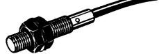
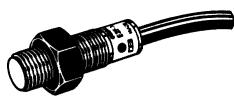
E2F-X1R5Y□
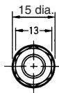
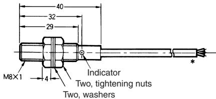
Note:
Vinyl-insulated round cord, 3.5 dia., 3 cores (0.12 dia. x 13); Standard length: 2 m
CAD file E2F_03
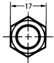
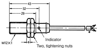
E2F-X2Y□
CAD file
E2F_05
E2F-X5Y□
Note:
Oil-and vibration-resistant, vinyl-insulated round cord, 6 dia., 0.5 dia. x 2 cores; Standard length: 2m The cord can be extended up to 200m in an independent metal conduit.
CAD file E2F_06
CAD file
E2F_01
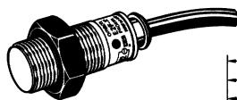
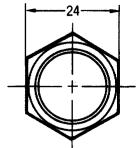
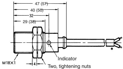
Note:
Oil-and vibration-resistant, vinyl-insulated round cord, 6 dia., 0.5 dia. x 2 cores; Standard length: 2m The cord can be extended up to 200m in an independent metal conduit.
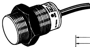
E2F-X10Y□
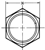
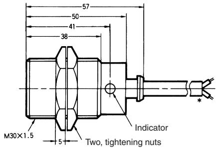
Note:
Oil-and vibration-resistant, vinyl-insulated round cord, 6 dia., 0.5 dia. × 2 cores; Standard length: 2m The cord can be extended up to 200m in an independent metal conduit.
Mounting Hole Dimension
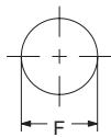
| Model | E2F-X1R5□□ | E2F-X2□□ | E2F-X5□□ | E2F-X10□□ |
| F (mm) | 8.5 +0.5 dia. | 12.5+0.5 dia. | 18.5+0.5 dia. | 30.5+0.5 dia. |
Pre-wired Models (Shielded)
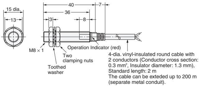
Fig.1:E2E-X1R5Y
Pre-wired Models (Unshielded)
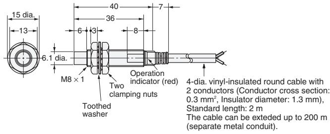
Fig.2:E2E-X2MY
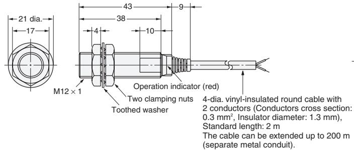
Fig.3:E2E-X2Y
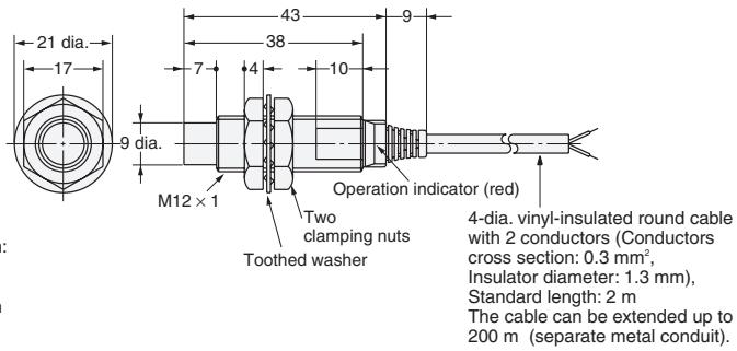
Fig.4:E2E-X5MY
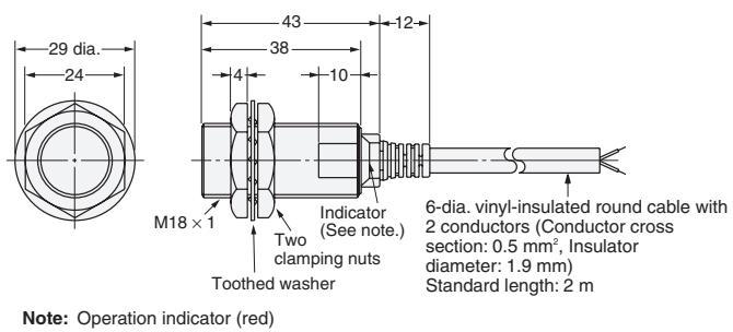
Fig.5:E2E-X5Y
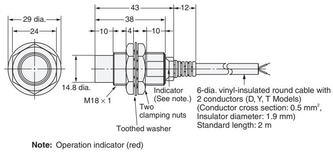
Fig.6:E2E-X10MY
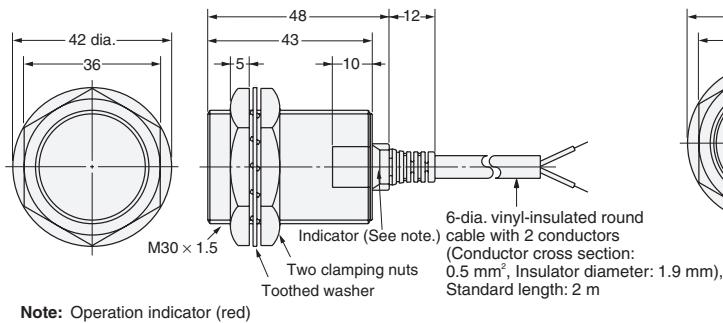
Fig.7: E2E-X10Y
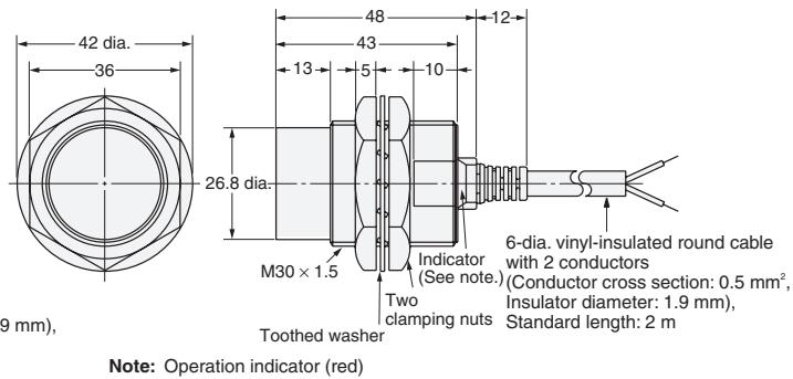
Fig.8:E2E-X18MY
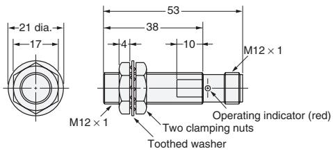
Fig.9:E2E-X2Y□-M1
Fig.11:E2E-X5Y□-M1
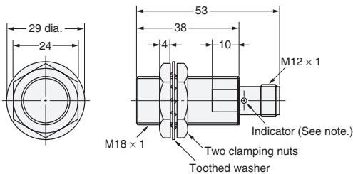
Note: Operation indicator (red)
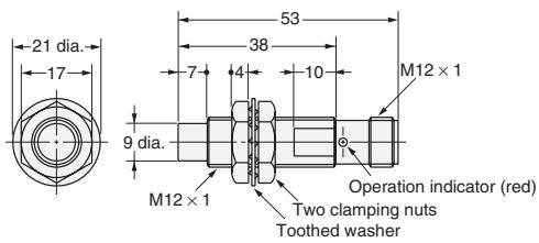
Fig.10:E2E-X5MY□-M1
Fig.12:E2E-X10MY□-M1
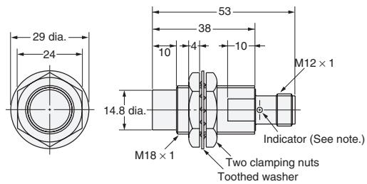
Note: Operation indicator (red)
Fig.13:E2E-X10Y□-M1
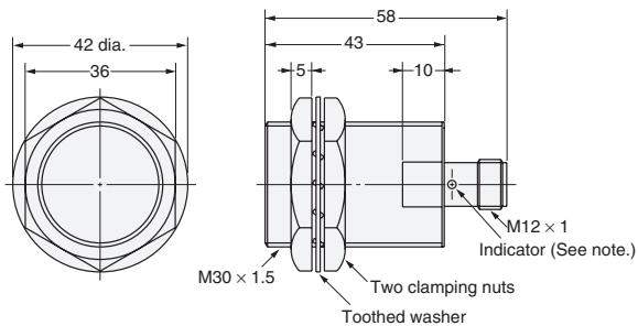
Note: Operation indicator (red)
Fig.14:E2E-X18MY□-M1
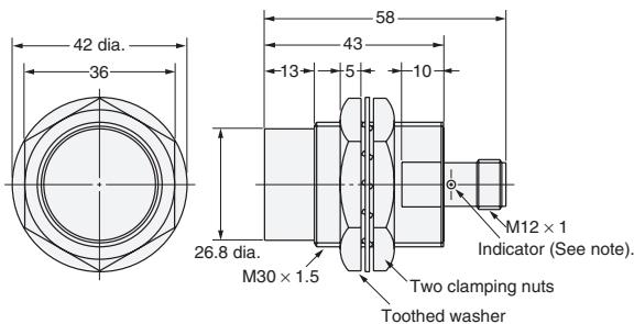
Note: Operation indicator (red)
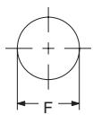
Mounting Hole Dimension
| Dimensions | M8 | M12 | M18 | M30 |
| F (mm) | 8.5+0.50 dia. | 12.5+0.50 dia. | 18.5+0.50 dia. | 30.5+0.50 dia. |
Warranties and Limitations of Liability
WARRANTY
OMRON's exclusive warranty is that the products are free from defects in materials and workmanship for a period of one year (or other period if specified) from date of sale by OMRON. OMRON MAKES NO WARRANTY OR REPRESENTATION, EXPRESS OR IMPLIED, REGARDING NON-INFRINGEMENT, MERCHANTABILITY, OR FITNESS FOR PARTICULAR PURPOSE OF THE PRODUCTS. ANY BUYER OR USER ACKNOWLEDGES THAT THE BUYER OR USER ALONE HAS DETERMINED THAT THE PRODUCTS WILL SUITABLY MEET THE REQUIREMENTS OF THEIR INTENDED USE. OMRON DISCLAIMS ALL OTHER WARRANTYES, EXPRESS OR IMPLIED.
LIMITATIONS OF LIABILITY
OMRON SHALL NOT BE RESPONSIBLE FOR SPECIAL, INDIRECT, OR CONSEQUENTIAL DAMAGES, LOSS OF PROFITS OR COMMERCIAL LOSS IN ANY WAY CONNECTED WITH THE PRODUCTS, WHETHER SUCH CLAIM IS BASED ON CONTRACT, WARRANTY, NEGLIGENCE, OR STRICT LIABILITY. In no event shall responsibility of OMRON for any act exceed the individual price of the product on which liability is asserted. IN NO EVENT SHALL OMRON BE RESPONSIBLE FOR WARRANTY, REPAIR, OR OTHER CLAIMS REGARDING THE PRODUCTS UNLESS OMRON'S ANALYSIS CONFIRMS THAT THE PRODUCTS WERE PROPERLY HANDLED, STORED, INSTALLED, AND MAINTAINED AND NOT SUBJECT TO CONTAMINATION, ABUSE, MISUSE, OR INAPPROPRIATE MODIFICATION OR REPAIR.
Application Considerations
SUITABILITY FOR USE
THE PRODUCTS CONTAINED IN THIS CATALOG ARE NOT SAFETY RATED. THEY ARE NOT DESIGNED OR RATED FOR ENSURING SAFETY OF PERSONS, AND SHOULD NOT BE RELIED UPON AS A SAFETY COMPONENT OR PROTECTIVE DEVICE FOR SUCH PURPOSES. Please refer to separate catalogs for OMRON's safety rated products.
OMRON shall not be responsible for conformity with any standards, codes, or regulations that apply to the combination of products in the customer's application or use of the product.
Take all necessary steps to determine the suitability of the product for the systems, machines, and equipment with which it will be used. Know and observe all prohibitions of use applicable to this product. NEVER USE THE PRODUCT FOR AN APPLICATION INVOLVING SERIOUS RISK TO LIFE OR PROPERTY WITHOUT ENSURING THAT THE SYSTEM AS A WHOLE HAS BEEN DESIGNED TO ADDRESS THE RISKS, AND THAT THE OMRON PRODUCT IS PROPERLY RATED AND INSTALLED FOR THE INTENDED USE WITHIN THE OVERALL EQUIPMENT OR SYSTEM.
Disclaimers
CHANGE IN SPECIFICATIONS
Product specifications and accessories may be changed at any time based on improvements and other reasons. Consult with your OMRON representative at any time to confirm actual specifications of purchased product.
DIMENSIONS AND WEIGHTS
Dimensions and weights are nominal and are not to be used for manufacturing purposes, even when tolerances are shown.
Cat. No. D14E-EN-01
In the interest of product improvement, specifications are subject to change without notice.
OMRON EUROPE B.V.
Wegalaan 67-69,
NL-2132 JD, Hoofddorp,
The Netherlands
Phone: +31 23 568 13 00
Fax: +31 23 568 13 88
www.eu.omron.com
- Cylindrical Inductive Sensor for AC Power Supply
- E2E- □Y/E2F- □Y
- Ordering Information
- Plastic Housing
- Metal Housing
- Specifications
- Pin Arrangement
- Installation
- Precautions
- Mounting
- Influence of Surrounding Metal
- Mutual Interference
- WARNING
- Precautions for Safe Use
- Precautions for Correct Use
- Power Reset Time
- Power OFF
- Power Supply Transformer
- Sensing Object
- High-tension Lines
- Cable Tractive Force
- Environment
- Water Resistivity
- Operating Environment
- Connecting Load to AC 2-wire Sensor
- Surge Protection
- Leakage Current
- Countermeasures Against Leakage Current
- AC 2-wire Models
- Precautions for AC 2-wire Proximity Sensors in Operation Connection
- Dimensions
- Mounting Hole Dimension
- Pre-wired Models (Shielded)
- Pre-wired Models (Unshielded)
- Warranties and Limitations of Liability
- WARRANTY
- LIMITATIONS OF LIABILITY
- Application Considerations
- SUITABILITY FOR USE
- Disclaimers
- CHANGE IN SPECIFICATIONS
- DIMENSIONS AND WEIGHTS
- OMRON EUROPE B.V.
Brand : OMRON
Model : E2F-Y
Category : Proximity Sensors