
E2A - Proximity Sensors OMRON - Free user manual and instructions
Find the device manual for free E2A OMRON in PDF.


| Product type | Inductive proximity sensor |
| Brand | OMRON |
| Model | E2A |
| Detection diameter | M8, M12, M18, M30 depending on variant |
| Nominal sensing distance | 2 mm (M8), 4 mm (M12), 8 mm (M18), 15 mm (M30) |
| Power supply | 10 to 30 V DC |
| Power consumption | Max. 10 mA (no load) |
| Output | NPN or PNP, Normally Open (NO) or Normally Closed (NC) |
| Switching frequency | Up to 1 kHz (depending on variant) |
| Housing material | Nickel-plated brass or stainless steel |
| Protection rating | IP67 |
| Operating temperature | -25 °C to +70 °C |
| Connection | PVC cable 2 m or M8/M12 connector |
| Main functions | Contactless detection of metal objects, LED status indicator |
| Maintenance and cleaning | Clean with a dry, non-abrasive cloth. Avoid solvents. |
| Safety | Follow wiring instructions and sensing distances. Use a stabilized power supply. |
| Spare parts and repairability | Not user-repairable. Replace the entire sensor if faulty. |
| General information | Cylindrical inductive sensor, mounting with nuts. Use in industrial automation. |
Frequently Asked Questions - E2A OMRON
User questions about E2A OMRON
0 question about this device. Answer the ones you know or ask your own.
Ask a new question about this device
Download the instructions for your Proximity Sensors in PDF format for free! Find your manual E2A - OMRON and take your electronic device back in hand. On this page are published all the documents necessary for the use of your device. E2A by OMRON.
USER MANUAL E2A OMRON
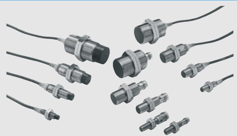
Cylindrical Proximity Sensor
E2A
High quality for extra long life in daily use
- wide portfolio range through modular concept
- designed and tested for extra long life
- IP67 and IP69k for highest protection in wet environments
- continuously high quality level through specialized manufacturing process
DC 3-wire and DC 2-wire models - Normally open (NO), normally closed (NC) and antivalent (NO+NC) models
- up to 30mm sensing distance
- Stainless steel and brass housings
- Pre-wired versions with different cable materials and diameters, M8 and M12 connector types, pre-wired types with cable end connectors
C E
Ordering Information
DC 3-wire models (NO + NC: DC 4-wire) *2
| Size | Sensing distance | Connec-tion | Body material | Thread length (overall length) | Output configu-guration | Operation mode NO | Operation mode NC | |
| M8 | Shiel-DED | 2.0 mm | Pre-wired | Stain-less steel*1 | 27 (40) | PNP | E2A-S08KS02-WP-B1 2M | E2A-S08KS02-WP-B2 2M |
| NPN | E2A-S08KS02-WP-C1 2M | E2A-S08KS02-WP-C2 2M | ||||||
| 49 (62) | PNP | E2A-S08LS02-WP-B1 2M | E2A-S08LS02-WP-B2 2M | |||||
| NPN | E2A-S08LS02-WP-C1 2M | E2A-S08LS02-WP-C2 2M | ||||||
| M12 connector | 27 (43) | PNP | E2A-S08KS02-M1-B1 | E2A-S08KS02-M1-B2 | ||||
| NPN | E2A-S08KS02-M1-C1 | E2A-S08KS02-M1-C2 | ||||||
| 49 (65) | PNP | E2A-S08LS02-M1-B1 | E2A-S08LS02-M1-B2 | |||||
| NPN | E2A-S08LS02-M1-C1 | E2A-S08LS02-M1-C2 | ||||||
| M8 connector (3-pin) | 27 (39) | PNP | E2A-S08KS02-M5-B1 | E2A-S08KS02-M5-B2 | ||||
| NPN | E2A-S08KS02-M5-C1 | E2A-S08KS02-M5-C2 | ||||||
| 49 (61) | PNP | E2A-S08LS02-M5-B1 | E2A-S08LS02-M5-B2 | |||||
| NPN | E2A-S08LS02-M5-C1 | E2A-S08LS02-M5-C2 | ||||||
| M8 connector (4-pin) | 27 (39) | PNP | E2A-S08KS02-M3-B1 | E2A-S08KS02-M3-B2 | ||||
| NPN | E2A-S08KS02-M3-C1 | E2A-S08KS02-M3-C2 | ||||||
| 49 (61) | PNP | E2A-S08LS02-M3-B1 | E2A-S08LS02-M3-B2 | |||||
| NPN | E2A-S08LS02-M3-C1 | E2A-S08LS02-M3-C2 | ||||||
| Non-shiel-DED | 4.0 mm | Pre-wired | 27 (40) | PNP | E2A-S08KN04-WP-B1 2M | E2A-S08KN04-WP-B2 2M | ||
| NPN | E2A-S08KN04-WP-C1 2M | E2A-S08KN04-WP-C2 2M | ||||||
| 49 (62) | PNP | E2A-S08LN04-WP-B1 2M | E2A-S08LN04-WP-B2 2M | |||||
| NPN | E2A-S08LN04-WP-C1 2M | E2A-S08LN04-WP-C2 2M | ||||||
| M12 connector | 27 (43) | PNP | E2A-S08KN04-M1-B1 | E2A-S08KN04-M1-B2 | ||||
| NPN | E2A-S08KN04-M1-C1 | E2A-S08KN04-M1-C2 | ||||||
| 49 (65) | PNP | E2A-S08LN04-M1-B1 | E2A-S08LN04-M1-B2 | |||||
| NPN | E2A-S08LN04-M1-C1 | E2A-S08LN04-M1-C2 | ||||||
| M8 connector (3-pin) | 27 (39) | PNP | E2A-S08KN04-M5-B1 | E2A-S08KN04-M5-B2 | ||||
| NPN | E2A-S08KN04-M5-C1 | E2A-S08KN04-M5-C2 | ||||||
| 49 (61) | PNP | E2A-S08LN04-M5-B1 | E2A-S08LN04-M5-B2 | |||||
| NPN | E2A-S08LN04-M5-C1 | E2A-S08LN04-M5-C2 | ||||||
| M8 connector (4 pin) | 27 (39) | PNP | E2A-S08KN04-M3-B1 | E2A-S08KN04-M3-B2 | ||||
| NPN | E2A-S08KN04-M3-C1 | E2A-S08KN04-M3-C2 | ||||||
| 49 (61) | PNP | E2A-S08LN04-M3-B1 | E2A-S08LN04-M3-B2 | |||||
| NPN | E2A-S08LN04-M3-C1 | E2A-S08LN04-M3-C2 | ||||||
| Size | Sensing distance | Connec-tion | Body material | Thread length (overall length) | Output confi-guration | Operation mode NO | Operation mode NC | Operation mode NO + NC | |
| M12 | Shiel-DED | 4.0 mm | Pre-wired | Brass*3 | 34 (50) | PNP | E2A-M12KS04-WP-B1 2M | E2A-M12KS04-WP-B2 2M | E2A-M12KS04-WP-B3 2M |
| NPN | E2A-M12KS04-WP-C1 2M | E2A-M12KS04-WP-C2 2M | E2A-M12KS04-WP-C3 2M | ||||||
| 56 (72) | PNP | E2A-M12LS04-WP-B1 2M | E2A-M12LS04-WP-B2 2M | E2A-M12LS04-WP-B3 2M | |||||
| NPN | E2A-M12LS04-WP-C1 2M | E2A-M12LS04-WP-C2 2M | E2A-M12LS04-WP-C3 2M | ||||||
| M12 connector | Brass*3 | 34 (48) | PNP | E2A-M12KS04-M1-B1 | E2A-M12KS04-M1-B2 | E2A-M12KS04-M1-B3 | |||
| NPN | E2A-M12KS04-M1-C1 | E2A-M12KS04-M1-C2 | E2A-M12KS04-M1-C3 | ||||||
| 56 (70) | PNP | E2A-M12LS04-M1-B1 | E2A-M12LS04-M1-B2 | E2A-M12LS04-M1-B3 | |||||
| NPN | E2A-M12LS04-M1-C1 | E2A-M12LS04-M1-C2 | E2A-M12LS04-M1-C3 | ||||||
| M8 connector (3-pin) | Brass*3 | 34 (48) | PNP | E2A-M12KS04-M5-B1 | E2A-M12KS04-M5-B2 | n.a. | |||
| NPN | E2A-M12KS04-M5-C1 | E2A-M12KS04-M5-C2 | n.a. | ||||||
| 56 (70) | PNP | E2A-M12LS04-M5-B1 | E2A-M12LS04-M5-B2 | n.a. | |||||
| NPN | E2A-M12LS04-M5-C1 | E2A-M12LS04-M5-C2 | n.a. | ||||||
| M8 connector (4-pin) | Brass*3 | 34 (48) | PNP | E2A-M12KS04-M3-B1 | E2A-M12KS04-M3-B2 | n.a. | |||
| NPN | E2A-M12KS04-M3-C1 | E2A-M12KS04-M3-C2 | n.a. | ||||||
| 56 (70) | PNP | E2A-M12LS04-M3-B1 | E2A-M12LS04-M3-B2 | n.a. | |||||
| NPN | E2A-M12LS04-M3-C1 | E2A-M12LS04-M3-C2 | n.a. | ||||||
| Non-shiel-DED | 8.0 mm | Pre-wired | Brass*3 | 34 (50) | PNP | E2A-M12KN08-WP-B1 2M | E2A-M12KN08-WP-B2 2M | E2A-M12KN08-WP-B3 2M | |
| NPN | E2A-M12KN08-WP-C1 2M | E2A-M12KN08-WP-C2 2M | E2A-M12KN08-WP-C3 2M | ||||||
| 56 (72) | PNP | E2A-M12LN08-WP-B1 2M | E2A-M12LN08-WP-B2 2M | E2A-M12LN08-WP-B3 2M | |||||
| NPN | E2A-M12LN08-WP-C1 2M | E2A-M12LN08-WP-C2 2M | E2A-M12LN08-WP-C3 2M | ||||||
| M12 connector | Brass*3 | 34 (48) | PNP | E2A-M12KN08-M1-B1 | E2A-M12KN08-M1-B2 | E2A-M12KN08-M1-B3 | |||
| NPN | E2A-M12KN08-M1-C1 | E2A-M12KN08-M1-C2 | E2A-M12KS08-M1-C3 | ||||||
| 56 (70) | PNP | E2A-M12LN08-M1-B1 | E2A-M12LN08-M1-B2 | E2A-M12LS08-M1-B3 | |||||
| NPN | E2A-M12LN08-M1-C1 | E2A-M12LN08-M1-C2 | E2A-M12LS08-M1-C3 | ||||||
| M8 connector (3-pin) | Brass*3 | 34 (48) | PNP | E2A-M12KN08-M5-B1 | E2A-M12KN08-M5-B2 | n.a. | |||
| NPN | E2A-M12KN08-M5-C1 | E2A-M12KN08-M5-C2 | n.a. | ||||||
| 56 (70) | PNP | E2A-M12LN08-M5-B1 | E2A-M12LN08-M5-B2 | n.a. | |||||
| NPN | E2A-M12LN08-M5-C1 | E2A-M12LN08-M5-C2 | n.a. | ||||||
| M8 connector (4-pin) | Brass*3 | 34 (48) | PNP | E2A-M12KN08-M3-B1 | E2A-M12KN08-M3-B2 | n.a. | |||
| NPN | E2A-M12LN08-M3-C1 | E2A-M12LN08-M3-C2 | n.a. | ||||||
| 56 (70) | PNP | E2A-M12LN08-M3-B1 | E2A-M12LN08-M3-B2 | n.a. | |||||
| NPN | E2A-M12LN08-M3-C1 | E2A-M12LN08-M3-C2 | n.a. | ||||||
| M18 | Shiel-DED | 8.0 mm | Pre-wired | Brass*3 | 39 (59) | PNP | E2A-M18KS08-WP-B1 2M | E2A-M18KS08-WP-B2 2M | E2A-M18KS08-WP-B3 2M |
| NPN | E2A-M18KS08-WP-C1 2M | E2A-M18KS08-WP-C2 2M | E2A-M18KS08-WP-C3 2M | ||||||
| 61 (81) | PNP | E2A-M18LS08-WP-B1 2M | E2A-M18LS08-WP-B2 2M | E2A-M18LS08-WP-B3 2M | |||||
| NPN | E2A-M18LS08-WP-C1 2M | E2A-M18LS08-WP-C2 2M | E2A-M18LS08-WP-C3 2M | ||||||
| M12 connector | Brass*3 | 39 (53) | PNP | E2A-M18KS08-M1-B1 | E2A-M18KS08-M1-B2 | E2A-M18KS08-M1-B3 | |||
| NPN | E2A-M18KS08-M1-C1 | E2A-M18KS08-M1-C2 | E2A-M18KS08-M1-C3 | ||||||
| 61 (75) | PNP | E2A-M18LS08-M1-B1 | E2A-M18LS08-M1-B2 | E2A-M18LS08-M1-B3 | |||||
| NPN | E2A-M18LS08-M1-C1 | E2A-M18LS08-M1-C2 | E2A-M18LS08-M1-C3 | ||||||
| M8 connector (3-pin) | Brass*3 | 39 (53) | PNP | E2A-M18KS08-M3-B1 | E2A-M18KS08-M3-B2 | n.a. | |||
| NPN | E2A-M18KS08-M3-C1 | E2A-M18KS08-M3-C2 | n.a. | ||||||
| 61 (75) | PNP | E2A-M18LS08-M3-B1 | E2A-M18LS08-M3-B2 | n.a. | |||||
| NPN | E2A-M18LS08-M3-C1 | E2A-M18LS08-M3-C2 | n.a. | ||||||
| Non-shiel-DED | 16.0 mm | Pre-wired | Brass*3 | 39 (59) | PNP | E2A-M18KN16-WP-B1 2M | E2A-M18KN16-WP-B2 2M | E2A-M18KN16-WP-B3 2M | |
| NPN | E2A-M18KN16-WP-C1 2M | E2A-M18KN16-WP-C2 2M | E2A-M18KN16-WP-C3 2M | ||||||
| 61 (81) | PNP | E2A-M18LN16-WP-B1 2M | E2A-M18LN16-WP-B2 2M | E2A-M18LN16-WP-B3 2M | |||||
| NPN | E2A-M18LN16-WP-C1 2M | E2A-M18LN16-WP-C2 2M | E2A-M18LN16-WP-C3 2M | ||||||
| M12 connector | Brass*3 | 39 (53) | PNP | E2A-M18KN16-M1-B1 | E2A-M18KN16-M1-B2 | E2A-M18KN16-M1-B3 | |||
| NPN | E2A-M18LN16-M1-C1 | E2A-M18KN16-M1-C2 | E2A-M18KS16-M1-C3 | ||||||
| 61 (75) | PNP | E2A-M18LN16-M1-B1 | E2A-M18LN16-M1-B2 | E2A-M18LS16-M1-B3 | |||||
| NPN | E2A-M18LN16-M1-C1 | E2A-M18LN16-M1-C2 | E2A-M18LS16-M1-C3 | ||||||
| M8 connector (3-pin) | Brass*3 | 39 (53) | PNP | E2A-M18KN16-M5-B1 | E2A-M18KN16-M5-B2 | n.a. | |||
| NPN | E2A-M18KN16-M5-C1 | E2A-M18KN16-M5-C2 | n.a. | ||||||
| 61 (75) | PNP | E2A-M18LN16-M5-B1 | E2A-M18LN16-M5-B2 | n.a. | |||||
| NPN | E2A-M18LN16-M5-C1 | E2A-M18LN16-M5-C2 | n.a. | ||||||
| M8 connector (4-pin) | Brass*3 | 39 (53) | PNP | E2A-M18KN16-M3-B1 | E2A-M18KN16-M3-B2 | n.a. | |||
| NPN | E2A-M18LN16-M3-C1 | E2A-M18LN16-M3-C2 | n.a. | ||||||
| 61 (75) | PNP | E2A-M18LN16-M3-B1 | E2A-M18LN16-M3-B2 | n.a. | |||||
| NPN | E2A-M18LN16-M3-C1 | E2A-M18LN16-M3-C2 | n.a. | ||||||
| Size | Sensing distance | Connec-tion | Body material | Thread length (overall length) | Output config-guration | Operation mode NO | Operation mode NC | Operation mode NO + NC | |
| M30 | Shiel-DED | 15.0 mm | Pre-wired | Brass*3 | 44 (64) | PNP | E2A-M30KS15-WP-B1 2M | E2A-M30KS15-WP-B2 2M | E2A-M30KS15-WP-B3 2M |
| NPN | E2A-M30KS15-WP-C1 2M | E2A-M30KS15-WP-C2 2M | E2A-M30KS15-WP-C3 2M | ||||||
| 66 (86) | PNP | E2A-M30LS15-WP-B1 2M | E2A-M30LS15-WP-B2 2M | E2A-M30LS15-WP-B3 2M | |||||
| NPN | E2A-M30LS15-WP-C1 2M | E2A-M30LS15-WP-C2 2M | E2A-M30LS15-WP-C3 2M | ||||||
| M12 connector | Brass*3 | 44 (58) | PNP | E2A-M30KS15-M1-B1 | E2A-M30KS15-M1-B2 | E2A-M30KS15-M1-B3 | |||
| NPN | E2A-M30KS15-M1-C1 | E2A-M30KS15-M1-C2 | E2A-M30KS15-M1-C3 | ||||||
| 66 (80) | PNP | E2A-M30LS15-M1-B1 | E2A-M30LS15-M1-B2 | E2A-M30LS15-M1-B3 | |||||
| NPN | E2A-M30LS15-M1-C1 | E2A-M30LS15-M1-C2 | E2A-M30LS15-M1-C3 | ||||||
| M8 connector (3-pin) | Brass*3 | 44 (58) | PNP | E2A-M30KS15-M5-B1 | E2A-M30KS15-M5-B2 | n.a. | |||
| NPN | E2A-M30KS15-M5-C1 | E2A-M30KS15-M5-C2 | n.a. | ||||||
| 66 (80) | PNP | E2A-M30LS15-M5-B1 | E2A-M30LS15-M5-B2 | n.a. | |||||
| NPN | E2A-M30LS15-M5-C1 | E2A-M30LS15-M5-C2 | n.a. | ||||||
| M8 connector (4-pin) | Brass*3 | 44 (58) | PNP | E2A-M30KS15-M3-B1 | E2A-M30KS15-M3-B2 | n.a. | |||
| NPN | E2A-M30KS15-M3-C1 | E2A-M30KS15-M3-C2 | n.a. | ||||||
| 66 (80) | PNP | E2A-M30LS15-M3-B1 | E2A-M30LS15-M3-B2 | n.a. | |||||
| NPN | E2A-M30LS15-M3-C1 | E2A-M30LS15-M3-C2 | n.a. | ||||||
| Non-shiel-DED | 20.0 mm | Pre-wired | Brass*3 | 44 (64) (See note.) | PNP | E2A-M30KN20-WP-B1 2M | E2A-M30KN20-WP-B2 2M | E2A-M30KN20-WP-B3 2M | |
| 30.0 mm | NPN | E2A-M30KN20-WP-C1 2M | E2A-M30KN20-WP-C2 2M | E2A-M30KN20-WP-C3 2M | |||||
| 66 (86) | PNP | E2A-M30LN30-WP-B1 2M | E2A-M30LN30-WP-B2 2M | E2A-M30LN30-WP-B3 2M | |||||
| NPN | E2A-M30LN30-WP-C1 2M | E2A-M30LN30-WP-C2 2M | E2A-M30LN30-WP-C3 2M | ||||||
| 20.0 mm | M12 connector | Brass*3 | 44 (58) (See note.) | PNP | E2A-M30KN20-M1-B1 | E2A-M30KN20-M1-B2 | E2A-M30KN20-M1-B3 | ||
| NPN | E2A-M30KN20-M1-C1 | E2A-M30KN20-M1-C2 | E2A-M30KN20-M1-C3 | ||||||
| 30.0 mm | 66 (80) | PNP | E2A-M30LN30-M1-B1 | E2A-M30LN30-M1-B2 | E2A-M30LN30-M1-B3 | ||||
| NPN | E2A-M30LN30-M1-C1 | E2A-M30LN30-M1-C2 | E2A-M30LN30-M1-C3 | ||||||
| 20.0 mm | M8 connector (3-pin) | Brass*3 | 44 (58) (See note.) | PNP | E2A-M30KN20-M5-B1 | E2A-M30KN20-M5-B2 | n.a. | ||
| NPN | E2A-M30KN20-M5-C1 | E2A-M30KN20-M5-C2 | n.a. | ||||||
| 30.0 mm | 66 (80) | PNP | E2A-M30LN30-M5-B1 | E2A-M30LN30-M5-B2 | n.a. | ||||
| NPN | E2A-M30LN30-M5-C1 | E2A-M30LN30-M5-C2 | n.a. | ||||||
| 20.0 mm | M8 connector (4-pin) | Brass*3 | 44 (58) (See note.) | PNP | E2A-M30KN20-M3-B1 | E2A-M30KN20-M3-B2 | n.a. | ||
| NPN | E2A-M30KN20-M3-C1 | E2A-M30KN20-M3-C2 | n.a. | ||||||
| 30.0 mm | 66 (80) | PNP | E2A-M30LN30-M3-B1 | E2A-M30LN30-M3-B2 | n.a. | ||||
| NPN | E2A-M30LN30-M3-C1 | E2A-M30LN30-M3-C2 | n.a. | ||||||
*1. Material specifications for stainless steel housing case: 1.4305 (W.-No.), SUS 303 (AISI), 2346 (SS). Please contact your OMRON representative for other stainless steel materials.
2. Please contact your OMRON representative for DC 2-wire models.
3. Stainless steel models are also available. Please contact your OMRON representative.
Note:M30 non-shielded Models with double sensing distance and short barrels cannot be mounted due to the necessary separation distance from the surrounding metal. Standard sensing models are thus available.
The E2A sensors are available with the following connectors and cable materials:
Pre-wired models
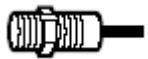
Standard cable lengths are 2m and 5m.
For other cable lengths please contact your OMRON representative.
Standard cable material: PVC (dia 4mm) -WP
Other available cable materials and sizes:
-PVC (dia 6mm) -WS
- PUR/PVC - PUR jacket (dia 4mm) -WA
- PUR/PVC - PUR jacket (dia 6mm)
- PVC robotic cable (dia 4mm) -WR
Pre-wired models with cable end connectors
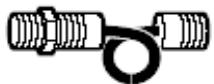
All pre-wired models can be fitted with cable and connectors.
Standard cable end connectors:
Other cable end connectors are available on request.
Connector models
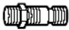
Standard connectors: M12, M8 (4 or 3 pin) -M1, -M3, -M5
Model Number Legend
E2A□-□□□□□-□-□□-□□
1 2 3 4 5 6 7 8 9 10 11 12
Example: E2A-M12LS04-M1-B1
E2A-S08KN04-WP-B1 5M
Standard, M12, long barrel, shielded, Sn=4 mm, M12 connector, PNP-NO
Standard, M8 stainless steel, short barrel, non-shielded, Sn=4 mm, pre-wired PVC cable, PNP-NO, cable length=5 m
- Basic name
E2A
- Sensing technology
Blank: Standard double distance
- Housing shape and material
M: Cylindrical, metric threaded, brass
S: Cylindrical, metric threaded, stainless steel
- Housing size
08: 8 mm
12: 12 mm
18: 18 mm
30: 30 mm
- Barrel length
K: Standard length
L: Long body
- Shield
S: Shielded
N: Non-shielded
- Sensing distance
Numeral: Sensing distance: e.g. 02 = 2mm 16 = 16mm
8. Kind of connection
WP: pre-wired, PVC, dia 4mm (standard)
WS: pre-wired, PVC, dia 6mm
WR: pre-wired, PVC, robotic cable, dia 4mm
WA: pre-wired, PUR/PVC (PUR jacket), dia 4mm
WB: pre-wired, PUR/PVC (PUR jacket), dia 6mm
M1: M12 connector (4 pin) *
M3: M8 connector (4 pin)
M5: M8 connector (3 pin)
M1J pre-wired with M12 cable end connector (4 pin)
M3J pre-wired with M8 cable end connector (4 pin)
M5J pre-wired with M8 cable end connector (3 pin)
- Power source and output
B: DC, 3-wire, PNP open collector
C: DC, 3-wire, NPN open collector
D: DC, 2-wire
E: DC, 3-wire, NPN voltage output
F: DC, 3-wire, PNP voltage output
- Operation mode
1: Normally open (NO)
2: Normally closed (NC)
3: Antivalent (NO+NC)
11.Specials (e.g., cable material, oscillating frequency)
12.Cable length
Blank: Connector type
Numeral: Cable length
Note: *In case of DC 2-wire models the M12 connector identifier is '-M1G'
DC 3-wire Models / DC 4-wire (NO+NC)
| Size | M8 | M12 | |||
| Type | Shielded | Non-shielded | Shielded | Non-shielded | |
| Item | E2A-S08□S02-□-B1E2A-S08□S02-□-C1 | E2A-S08□N04-□-B1E2A-S08□N04-□-C1 | E2A-M12□S04-□-B1E2A-M12□S04-□-C1E2A-S12□S04-□-B1E2A-S12□S04-□-C1 | E2A-M12□N08-□-B1E2A-M12□N08-□-C1E2A-S12□N08-□-B1E2A-S12□N08-□-C1 | |
| Sensing distance | 2 mm ±10% | 4 mm ±10% | 4 mm ±10% | 8 mm ±10% | |
| Setting distance | 0 to 1.6 mm | 0 to 3.2 mm | 0 to 3.2 mm | 0 to 6.4 mm | |
| Differential travel | 10% max. of sensing distance | ||||
| Target | Ferrous metal (The sensing distance decreases with non-ferrous metal.) | ||||
| Standard target (mild steel ST37) | 8×8×1 mm | 12×12×1 mm | 12×12×1 mm | 24×24×1 mm | |
| Response frequency (See note 1.) | 1,500 Hz | 1,000 Hz | 1,000 Hz | 800 Hz | |
| Power supply voltage (operating voltage range) | 12 to 24 VDC. Ripple (p-p): 10% max. (10 to 32 VDC) | ||||
| Current consumption (DC 3-wire) | 10 mA max. | ||||
| Output type | -B models: PNP open collector-C models: NPN open collector | ||||
| Control output | Load current (See note 2.) | 200 mA max. (32 VDC max.) | |||
| Residual voltage | 2 V max. (under load current of 200 mA with cable length of 2 m) | ||||
| Indicator | Operation indicator (Yellow LED) | ||||
| Operation mode (with sensing object approaching) | -B1/-C1 models: NO-B2/-C2 models: NC-B3/ -C3 models: NO+NC For details, refer to the timing charts. (See note 4.) | ||||
| Protection circuit | Power source circuit reverse polarity protection, Surge suppressor, Short-circuit protection | Output reverse polarity protection, Power source circuit reverse polarity protection, Surge suppressor, Short-circuit protection | |||
| Ambient air temperature | Operating: -40°C to 70°C, Storage: -40°C to 85°C (with no icing or condensation) | ||||
| Temperature influence (See note 2.) | ±10% max. of sensing distance at 23°C within temperature range of -25°C to 70°C ±15% max. of sensing distance at 23°C within temperature range of -40°C to 70°C | ||||
| Ambient humidity | Operating: 35% to 95%, Storage: 35% to 95% | ||||
| Voltage influence | ±1% max. of sensing distance in rated voltage range ±15% | ||||
| Insulation resistance | 50 MΩ min. (at 500 VDC) between current carry parts and case | ||||
| Dielectric strength | 1,000 VAC at 50/60 Hz for 1 min between current carry parts and case | ||||
| Vibration resistance | 10 to 55 Hz, 1.5-mm double amplitude for 2 hours each in X, Y and Z directions | ||||
| Shock resistance | 500 m/s2, 10 times each in X, Y and Z directions | 1,000 m/s2, 10 times each in X, Y and Z directions | |||
| Standard and listings (See note 3.) | IP67 after IEC 60529IP69k after DIN 40050EMC after EN60947-5-2 | ||||
| Connection method | Pre-wired models (standard is dia 4mm PVC cable with length = 2m). Please see chapter 'Connectivity' for details on different cable materials and lenghts and M8 or M12 connectors. | ||||
| Weight (packaged) | Pre-wired model | Approx. 65 g | Approx. 85 g | ||
| Connector model | M12 connector models: Approx. 20 gM8 connector models: Approx. 15 g | Approx. 35 g | |||
| Material | Case | Stainless steel | Brass-nickel plated or stainless steel | ||
| Sensing surface | PBT | ||||
| Cable | Standard cable is PVC dia 4mm. For other cable materials or diameters please refer to chapter 'Connectivity' | ||||
| Clamping nut | Brass-nickel plated | Brass-nickel plated for brass models stainless steel for steel models | |||
Note 1. The response frequency is an average value. Measurement conditions are as follows: standard target, a distance of twice the standard target distance between targets, and a setting distance of half the sensing distance.
2. When using any model at an ambient temperature between -40^ and -25^ and a power voltage between 30 and 32 VDC, use a load current of 100mA max.,
3. For USA and Canada: use class 2 circuit only.
4. -B3/ -C3 NO+NC models are available in M12, M18 and M30 housings with M12 connectors, pre-wired and with cable end connectors.
DC 3-wire Models / DC 4-wire (NO+NC)
| Size | M18 | M30 | ||||
| Type | Shielded | Non-shielded | Shielded | Non-shielded | Non-shielded | |
| Item | E2A-M18□S08-□-B□E2A-M18□S08-□-C□E2A-S18□S08-□-B□E2A-S18□S08-□-C□ | E2A-M18□N16-□-B□E2A-M18□N16-□-C□E2A-S18□N16-□-B□E2A-S18□N16-□-C□ | E2A-M30□S15-□-B□E2A-M30□S15-□-C□E2A-S30□S15-□-B□E2A-S30□S15-□-C□ | E2A-M30KN20-□-B□E2A-M30KN20-□-C□E2A-S30KN20-□-B□E2A-S30KN20-□-C□ | E2A-M30LN30-□-B□E2A-M30LN30-□-C□E2A-S30LN30-□-B□E2A-S30LN30-□-C□ | |
| Sensing distance | 8 mm±10% | 16 mm±10% | 15 mm±10% | 20 mm±10% | 30 mm±10% | |
| Setting distance | 0 to 6.4 mm | 0 to 12.8 mm | 0 to 12 mm | 0 to 16 mm | 0 to 24 mm | |
| Differential travel | 10% max. of sensing distance | |||||
| Target | Ferrous metal (The sensing distance decreases with non-ferrous metal.) | |||||
| Standard target(mild steel ST37) | 24×24×1 mm | 48×48×1 mm | 45×45×1 mm | 60×60×1 mm | 90×90×1 mm | |
| Response frequency(See note 1.) | 500 Hz | 400 Hz | 250 Hz | 100 Hz | 100 Hz | |
| Power supply voltage(operating voltage range) | 12 to 24 VDC. Ripple (p-p): 10% max.(10 to 32 VDC) | |||||
| Current consumption(DC 3-wire) | 10 mA max. | |||||
| Output type | -B models: PNP open collector-C models: NPN open collector | |||||
| Control output | Load current(See note 2.) | 200 mA max. (32 VDC max.) | ||||
| Residual voltage | 2 V max. (under load current of 200 mA with cable length of 2 m) | |||||
| Indicator | Operation indicator (Yellow LED) | |||||
| Operation mode(with sensing objectapproaching) | -B1/-C1 models: NO-B2/-C2 models: NC-B3/ -C3 models: NO+NCFor details, refer to the timing charts. | |||||
| Protection circuit | Output reverse polarity protection, Power source circuit reverse polarity protection, Surge suppressor,Short-circuit protection | |||||
| Ambient air temperature | Operating: -40°C to 70°C, Storage: -40°C to 85°C (with no icing or condensation) | |||||
| Temperature influence(See note 2.) | ±10% max. of sensing distance at 23°C within temperature range of -25°C to 70°C±15% max. of sensing distance at 23°C within temperature range of -40°C to 70°C | |||||
| Ambient humidity | Operating: 35% to 95%, Storage: 35% to 95% | |||||
| Voltage influence | ±1% max. of sensing distance in rated voltage range ±15% | |||||
| Insulation resistance | 50 MΩ min. (at 500 VDC) between current carry parts and case | |||||
| Dielectric strength | 1,000 VAC at 50/60 Hz for 1 min between current carry parts and case | |||||
| Vibration resistance | 10 to 55 Hz, 1.5-mm double amplitude for 2 hours each in X, Y and Z directions | |||||
| Shock resistance | 1,000 m/s2, 10 times each in X, Y and Z directions | |||||
| Standard and listings(Seetnote 3.) | IP67 after IEC 60529IP69k after DIN 40050EMC after EN60947-5-2 | |||||
| Connection method | Pre-wired models (standard is dia 4mm PVC cable with length = 2m).Please see chapter 'Connectivity' for details on different cable materials and lenghts and M8 or M12 connectors. | |||||
| Weight(pak-kaged) | Pre-wired model | Approx. 160 g | Approx. 280 g | Approx. 280 g | Approx. 370 g | |
| Connector model | Approx. 70 g | Approx. 200 g | Approx. 200 g | Approx. 260 g | ||
| Material | Case | Brass-nickel plated or stainless steel | ||||
| Sensing surface | PBT | |||||
| Cable | Standard cable is PVC dia 4mm. For other cable materials or diameters please refer to chapter 'Connectivity' | |||||
| Clamping nut | brass-nickel plated for brass models stainless steel for steel models | |||||
Note 1. The response frequency is an average value. Measurement conditions are as follows: standard target, a distance of twice the standard target distance between targets, and a setting distance of half the sensing distance.
2. When using any model at an ambient temperature between -40^ and -25^ and a power voltage between 30 and 32 VDC, use a load current of 100mA max.
3. For USA and Canada: use class 2 circuit only.
DC 2-wire Models
| Size | M8 | M12 | |||
| Type | Shielded | Non-shielded | Shielded | Non-shielded | |
| Item | E2A-S08□S02-D□ | E2A-S08□N04-D□ | E2A-M12□S04-D□E2A-S12□S04-D□ | E2A-M12□N08-D□E2A-S12□N08-D□ | |
| Sensing distance | 2 mm ±10% | 4 mm ±10% | 4 mm ±10% | 8 mm ±10% | |
| Setting distance | 0 to 1.6 mm | 0 to 3.2 mm | 0 to 3.2 mm | 0 to 6.4 mm | |
| Differential travel | 10% max. of sensing distance | ||||
| Target | Ferrous metal (The sensing distance decreases with non-ferrous metal.) | ||||
| Standard target | 8×8×1 mm | 12×12×1 mm | 12×12×1 mm | 24×24×1 mm | |
| Response frequency (See note 1.) | 1,500 Hz | 1,000 Hz | 1,000 Hz | 800 Hz | |
| Power supply voltage (operating voltage range) | 12 to 24 VDC. Ripple (p-p): 10% max. (10 to 32 VDC) | ||||
| Leakage current | 0.8 mA max. | ||||
| Output type | DC 2 wire type | ||||
| Control output | Load current (See note 2.) | 3 to 100 mA | |||
| Residual voltage | 3 V max. (under load current of 100 mA with cable length of 2 m) | ||||
| Indicator (see timing chart) | NO type: Operation indicator (Yellow), Setting indicator (Red) NC type: Operation indicator (Yellow) | ||||
| Operation mode | -D1 models: NO-D2 models: NC | ||||
| Protection circuit | Surget suppressor, Short circuit protection | ||||
| Ambient temperature | Operating: -40°C to 70°C, Storage: -40°C to 85°C (with no icing or condensation) | ||||
| Temperature influence | ±10% max. of sensing distance at 23°C within temperature range of -25°C to 70°C ±15% max. of sensing distance at 23°C within temperature range of -40°C to 70°C | ||||
| Ambient humidity | Operating: 35% to 95%, Storage: 35% to 95% | ||||
| Voltage influence | ±1% max. of sensing distance in rated voltage range ±15% | ||||
| Insulation resistance | 50 MΩ min. (at 500 VDC) between current carry parts and case | ||||
| Dielectric strength | 1,000 VAC at 50/60 Hz for 1 min between current carry parts and case | ||||
| Vibration resistance | 10 to 55 Hz, 1.5-mm double amplitude for 2 hours each in X, Y and Z directions | ||||
| Shock resistance | 500 m/s², 10 times each in X, Y and Z directions | 1,000 m/s², 10 times each in X, Y and Z directions | |||
| Standard and listings (See note 3.) | IP67 after IEC 60529IP69k after DIN 40050EMC after EN60947-5-2 | ||||
| Connection method | Pre-wired models (standard is dia 4mm PVC cable with length = 2m). Please see chapter 'Connectivity' for details on different cable materials and lenghts and M8 or M12 connectors. | ||||
| Weight (packaged) | Pre-wired model | Approx. 65 g | Approx. 85 g | ||
| Connector model | M12 connector models: Approx. 20 gM8 connector models: Approx. 15 g | Approx. 35 g | |||
| Material | Case | Stainless steel | Brass-nickel plated or stainless steel | ||
| Sensing surface | PBT | ||||
| Cable | Standard cable is PVC dia 4mm. For other cable materials or diameters please refer to chapter 'Connectivity' | ||||
| Clamping nut | Brass-nickel plated | Brass-nickel plated for brass models stainless steel for steel models | |||
Note 1. The response frequency is an average value. Measurement conditions are as follows: standard target, a distance of twice the standard target distance between targets, and a setting distance of half the sensing distance.
2. When using any model at an ambient temperature between -40^ and -25^ and a power voltage between 30 and 32 VDC, use a load current of 50mA max.
3. For USA and Canada: use class 2 circuit only.
DC 2-wire Models
| Size | M18 | M30 | |||
| Type | Shielded | Non-shielded | Shielded | Non-shielded | |
| Item | E2A-M18□S08-D□E2A-S18□S08-D□ | E2A-M18□N16-D□E2A-S18□N16-D□ | E2A-M30□S15-D□E2A-S30□S15-D□ | E2A-M30□N30-D□E2A-M30□N20-D□E2A-S30□N30-D□E2A-S30□N20-D□ | |
| Sensing distance | 8 mm ±10% | 16 mm ±10% | 15 mm ±10% | Short body: 20 m ±10%Long body: 30 m±10% | |
| Setting distance | 0 to 6.4 mm | 0 to 12.8 mm | 0 to 12 mm | Short body: 0 to 16 mmLong body: 0 to 24 mm | |
| Differential travel | 10% max. of sensing distance | ||||
| Target | Ferrous metal (The sensing distance decreases with non-ferrous metal.) | ||||
| Standard target | 24x24x1 mm | 48x48x1 mm | 45x45x1 mm | Short body: 60x60x1 mmLong body: 90x90x1mm | |
| Response frequency (See note 1.) | 500 Hz | 400 Hz | 250 Hz | 100 Hz | |
| Power supply voltage(operating voltage range) | 12 to 24 VDC. Ripple (p-p): 10% max.(10 to 32 VDC) | ||||
| Leakage current | 0.8 mA max. | ||||
| Output type | DC 2 wire type | ||||
| Control output | Load current(See note 2.) | 3 to 100 mA | |||
| Residual voltage | 3 V max. (under load current of 100 mA with cable length of 2 m) | ||||
| Indicator (see timing chart) | NO type: Operation indicator (Yellow), Setting indicator (Red)NC type: Operation indicator (Yellow) | ||||
| Operation mode | -D1 models: NO-D2 models: NC | ||||
| Protection circuit | Surget suppressor, Short circuit protection | ||||
| Ambient temperature | Operating: -40°C to 70°C, Storage: -40°C to 85°C (with no icing or condensation) | ||||
| Temperature influence | ±10% max. of sensing distance at 23°C within temperature range of -25°C to 70°C±15% max. of sensing distance at 23°C within temperature range of -40°C to 70°C | ||||
| Ambient humidity | Operating: 35% to 95%, Storage: 35% to 95% | ||||
| Voltage influence | ±1% max. of sensing distance in rated voltage range ±15% | ||||
| Insulation resistance | 50 MΩ min. (at 500 VDC) between current carry parts and case | ||||
| Dielectric strength | 1,000 VAC at 50/60 Hz for 1 min between current carry parts and case | ||||
| Vibration resistance | 10 to 55 Hz, 1.5-mm double amplitude for 2 hours each in X, Y and Z directions | ||||
| Shock resistance | 500 m/s2, 10 times each in X, Y and Z directions | ||||
| Standard and listings (See note 3.) | IP67 after IEC 60529IP69k after DIN 40050EMC after EN60947-5-2 | ||||
| Connection method | Pre-wired models (standard is dia 4mm PVC cable with length = 2m).Please see chapter 'Connectivity' for details on different cable materials and lenghts and M8 or M12 connectors. | ||||
| Weight(packaged) | Pre-wired model | Approx. 160 g | Approx. 280 g | short body: 280 glong body: 370 g | |
| Connector model | Approx. 70 g | Approx. 200 g | short body: 200 glong body: 260 g | ||
| Material | Case | Brass-nickel plated or stainless steel | |||
| Sensing surface | PBT | ||||
| Cable | Standard cable is PVC dia 4mm.For other cable materials or diameters please refer to chapter 'Connectivity' | ||||
| Clamping nut | brass-nickel plated for brass models stainless steel for steel models | ||||
Note 1. The response frequency is an average value. Measurement conditions are as follows: standard target, a distance of twice the standard target distance between targets, and a setting distance of half the sensing distance.
2. When using any model at an ambient temperature between -40^ and -25^ and a power voltage between 30 and 32 VDC, use a load current of 50mA max.
3. For USA and Canada: use class 2 circuit only.
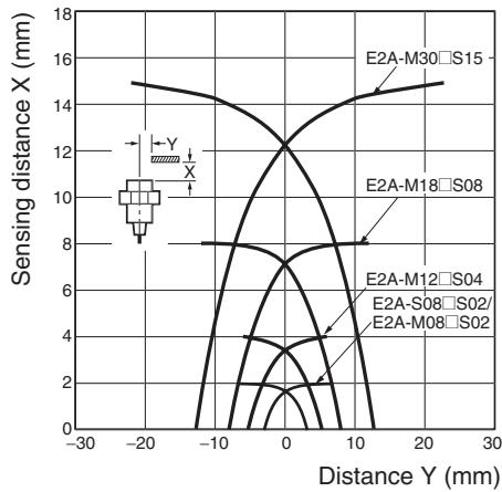
Operating Range (Typical)
Shielded Models
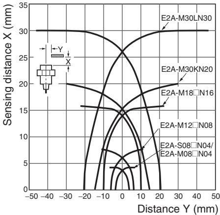
Non-shielded Models
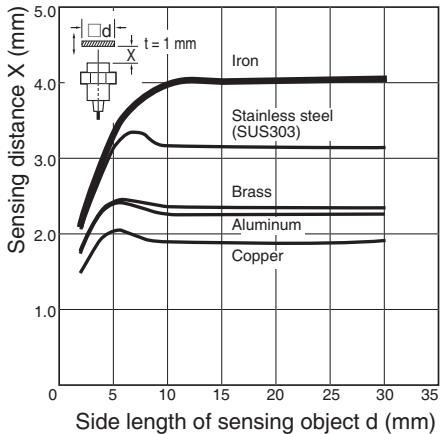
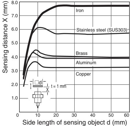
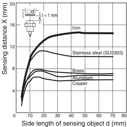
Influence of Sensing Object Size and Materials
Shielded Models
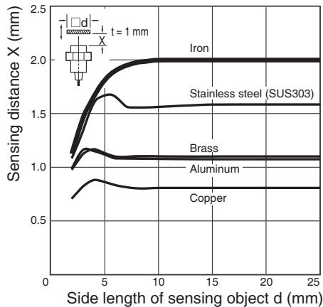
E2A-S08□S02
E2A-M12□S04/E2A-S12□S04
E2A-M18□S08/E2A-S18□S08
E2A-M30□S15/E2A-S30□S15
Non-shielded Models
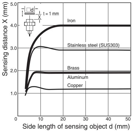
E2A-S08□N04
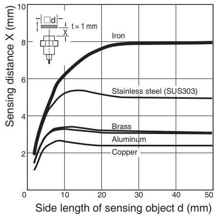
E2A-M12□N08/E2A-S12□N08
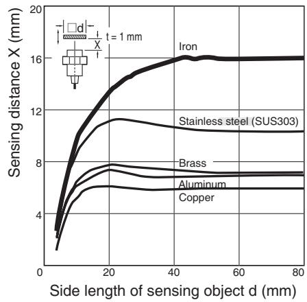
E2A-M18□N16/E2A-S18□N16
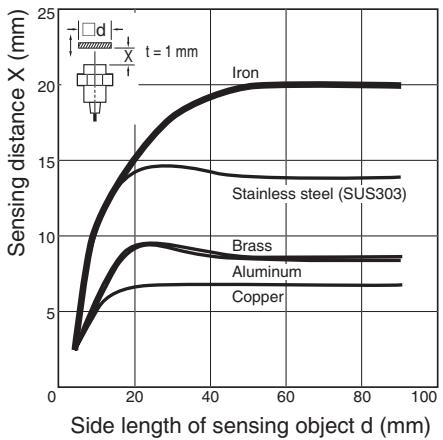
E2A-M30KN20/E2A-S30KN20
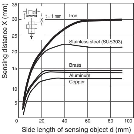
E2A-M30LN30/E2A-S30LN30
DC 3-wire models
PNP Output
| Operation mode | Model | Timing chart | Output circuit | |||
| NO | E2A-□-□-B1 | Non-sensing zone Sensing zone Proximity Sensor Sensing object (%) 100 sensing distance Rated distance ON yellow indicator OFF Control output | Brown (1) +V Black (4) Load Blue (3) 0 V Note 1: With M8 connector models, there is no output reverse polarity protection diode. M12 Connector M8 connector M8 Connector Pin Arrangement (See note 2.) Pin Arrangement Pin Arrangement (See note 2.) Note 2: Pin 2 of the M12 connector and M8 connector is not used. | |||
| NC | E2A-□-□-B2 | Non-sensing zone Sensing zone Proximity Sensor Sensing object (%) 100 sensing distance Rated distance ON yellow indicator OFF Control output | Brown (1) +V Black (2) (M8 connector: 4) Load Blue (3) 0 V Note 1: With M8 connector models, there is no output reverse polarity protection diode. M12 Connector M8 connector M8 Connector (4 pin) Pin Arrangement (See note 2.) Pin Arrangement (See note 2.) Note 2: Pin 4 of the M12 connector and M8 connector is not used. | |||
| NO + NC | E2A-□-□-B3 | Non-sensing zone Sensing zone Proximity Sensor Sensing object (%) 100 sensing distance Rated distance ON yellow indicator OFF Control output | Brown (1) +V Black (4) NO output Load White (2) NC output Load Blue (3) 0 V M12 Connector Pin Arrangement | |||
DC 3-wire models
NPN Output
| Operation mode | Model | Timing chart | Output circuit | |||
| NO | E2A-□-□-C1 | Non-sensing zone Sensing zone Proximity Sensor Sensing object (%) 100 distance Rated distance ON Yellow indicator OFF Control output | Brown ① +V Load Black ④ Blue ③ 0 V Note 1: With M8 connector models, there is no output reverse polarity protection diode. M12 Connector M8 connector (4 pin) Pin Arrangement (See note 2.) M8 Connector (4 pin) Pin Arrangement (See note 2.) Note 2: Pin 2 of the M12 connector and M8 connector is not used. | |||
| NC | E2A-□-□-C2 | Non-sensing zone Sensing zone Proximity Sensor Sensing object (%) 100 distance Rated distance ON Yellow indicator OFF Control output | Brown ① +V Load Black ② (M8 connector:④) Blue ③ 0 V Note 1: With M8 connector models, there is no output reverse polarity protection diode. M12 Connector M8 connector (4 pin) Pin Arrangement (See note 2.) M8 Connector (4 pin) Pin Arrangement (See note 2.) Note 2: Pin 4 of the M12 connector and M8 connector is not used. | |||
| NO + NC | E2A-□-□-C3 | Non-sensing zone Sensing zone Proximity Sensor Sensing object (%) 100 distance Rated distance ON Yellow indicator OFF Control output | Brown ① +V Load Black ④ NO output White ② NC output Blue ③ 0 V M12 Connector Pin Arrangement | |||
Output Circuit Diagrams (Operation)
DC 2-wire models
| Operation mode | Model | Timing chart | Output circuit | ||
| NO | E2A-□-D1 | Non-sensing zone Sensing zone Sensing object (%) 100 80 0 Load can be connected to +V or 0V side. | |||
| ON Yellow indicator OFF ON Red indicator OFF Control output | |||||
| ON OFF | |||||
| NC | E2A-□-D2 | Non-sensing zone Sensing zone Sensing object (%) 100 80 0 Load can be connected to +V or 0V side. | |||
| ON Yellow indicator OFF Control output | |||||
| ON OFF | |||||
Note: All units are in millimeters unless otherwise indicated. Pre-wired Models (Shielded)
E2A-S08KS02-WP-□□
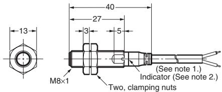
Note 1. 4-dia, vinyl-insulated round cable with 3 conductors (conductor cross section: 0.3mm^2 insulator diameter: 1.3mm standard length: 2m
2. Operation indicator (yellow)
E2A-M12KS04-WP-□/E2A-S12KS04-WP-□
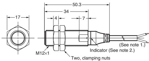
Note 1. 4-dia. vinyl-insulated round cable with 3 conductors (conductor cross section: 0.3mm^2 insulator diameter: 1.3mm standard length: 2m
2. Operation indicator (yellow)
3. for NO+NC (-B3 / -C3) models the total length is 4 mm longer
E2A-M18KS08-WP-□/E2A-S18KS08-WP-□
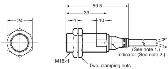
Note 1. 4-dia, vinyl-insulated round cable with 3 conductors (conductor cross section: 0.3mm^2 insulator diameter: 1.3mm standard length: 2m
2. Operation indicator (yellow)
E2A-M30KS15-WP-□/E2A-S30KS15-WP-
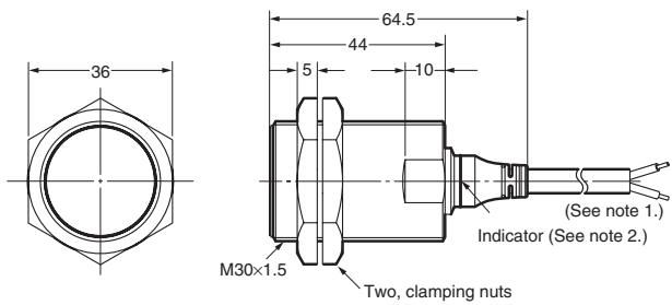
Note 1. 4-dia, vinyl-insulated round cable with 3 conductors (conductor cross section: 0.3mm insulator diameter: 1.3mm standard length: 2m
2. Operation indicator (yellow)
Pre-wired Models (Non-shielded)
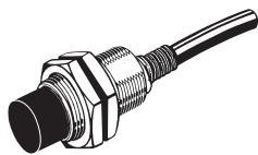
E2A-S08KN04-WP-□
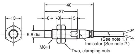
Note 1. 4-dia, vinyl-insulated round cable with 3 conductors (conductor cross section: 0.3mm^2 insulator diameter: 1.3mm standard length: 2m
2. Operation indicator (yellow)
E2A-M12KN08-WP-□/E2A-S12KN08-WP-
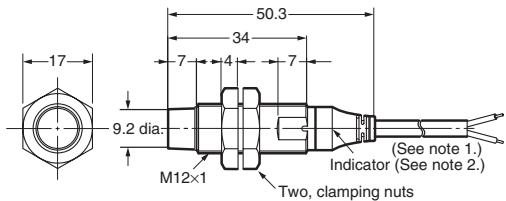
Note 1. 4-dia, vinyl-insulated round cable with 3 conductors (conductor cross section: 0.3mm^2 insulator diameter: 1.3mm standard length: 2m
2. Operation indicator (yellow)
3. for NO + NC (-B3/-C3) models the total length is 4mm longer
E2A-M18KN16-WP- /E2A-S18KN16-WP-
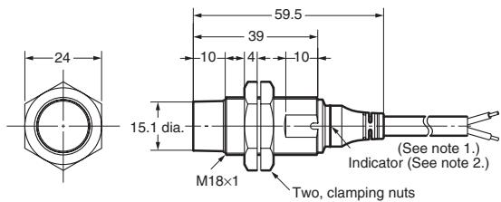
Note 1. 4-dia, vinyl-insulated round cable with 3 conductors (conductor cross section: 0.3mm^2 insulator diameter: 1.3mm standard length: 2m
2. Operation indicator (yellow)
E2A-M30KN20-WP-□/E2A-S30KN20-WP-
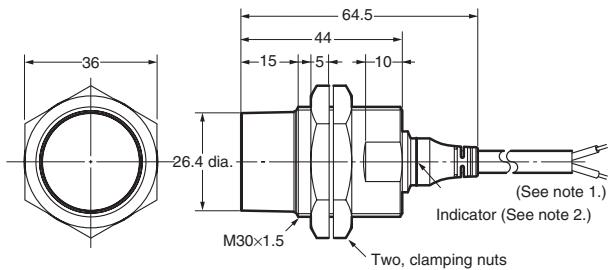
Note 1. 4-dia. vinyl-insulated round cable with 3 conductors (conductor cross section: 0.3mm^2 ; insulator diameter: 1.3mm ; standard length: 2m
2. Operation indicator (yellow)
E2A-S08LS02-WP-□
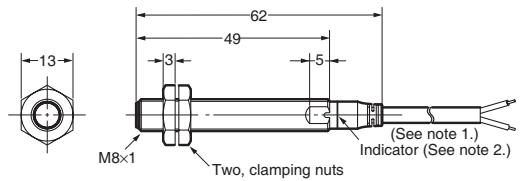
Note 1. 4-dia, vinyl-insulatored round cable with 3 conductors (conductor cross section: 0.3mm^2 insulator diameter: 1.3mm standard length: 2m
2. Operation indicator (yellow)
E2A-M12LS04-WP- /E2A-S12LS04-WP-
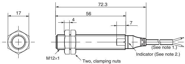
Note 1. 4-dia. vinyl-insulated round cable with 3 conductors (conductor cross section: 0.3mm^2 insulator diameter: 1.3mm standard length: 2m 2. Operation indicator (yellow)
E2A-M18LS08-WP- /E2A-S18LS08-WP-
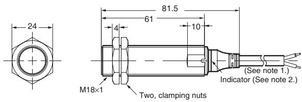
Note 1. 4-dia. vinyl-insulated round cable with 3 conductors (conductor cross section: 0.3mm^2 insulator diameter: 1.3mm standard length: 2m 2. Operation indicator (yellow)
E2A-M30LS15-WP- /E2A-S30LS15-WP-
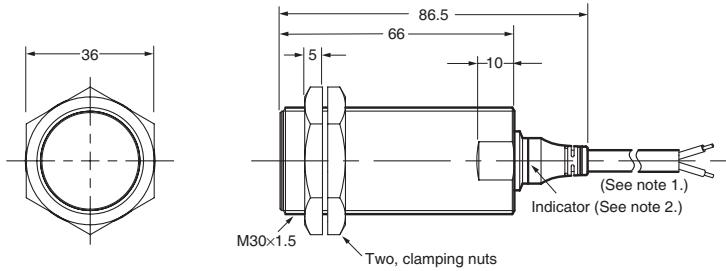
Note 1. 4-dia. vinyl-insulated round cable with 3 conductors (conductor cross section: 0.3mm^2 insulator diameter: 1.3mm standard length: 2m 2. Operation indicator (yellow)
E2A-S08LN04-WP-□
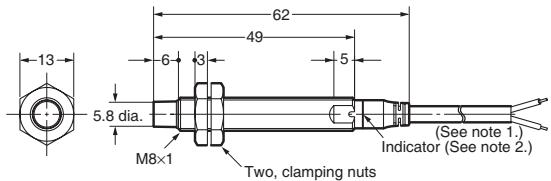
Note 1. 4-dia. vinyl-insulated round cable with 3 conductors (conductor cross section: 0.3mm^2 insulator diameter: 1.3mm standard length: 2m 2. Operation indicator (yellow)
E2A-M12LN08-WP-□/E2A-S12LN08-WP-
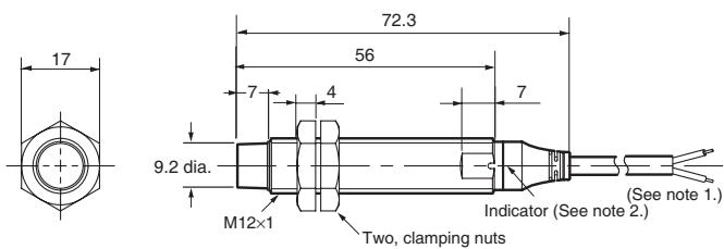
Note 1. 4-dia. vinyl-insulated round cable with 3 conductors (conductor cross section: 0.3mm^2 insulator diameter: 1.3mm standard length: 2m 2. Operation indicator (yellow)
E2A-M18LN16-WP-□/E2A-S18LN16-WP-
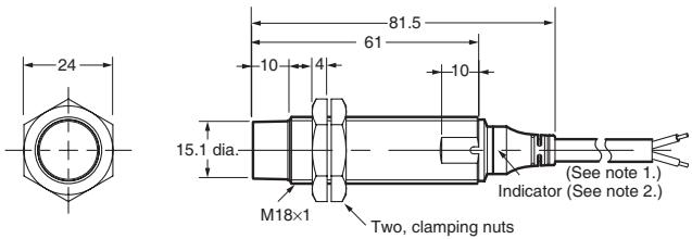
Note 1. 4-dia. vinyl-insulated round cable with 3 conductors (conductor cross section: 0.3mm^2 insulator diameter: 1.3mm standard length: 2m 2. Operation indicator (yellow)
E2A-M30LN30-WP- /E2A-S30LN30-WP-
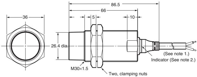
Note 1. 4-dia. vinyl-insulated round cable with 3 conductors (conductor cross section: 0.3mm^2 insulator diameter: 1.3mm standard length: 2m 2. Operation indicator (yellow)
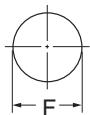
Mounting Hole Cutout Dimensions
| External diameter of Proximity Sensor | Dimension F (mm) |
| M8 | 8.5 dia. +0.5 0 |
| M12 | 12.5 dia. +0.5 0 |
| M18 | 18.5 dia. +0.5 0 |
| M30 | 30.5 dia. +0.5 0 |
M12 Connector Models (Shielded)
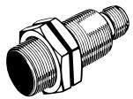
E2A-S08KS02-M1-□□
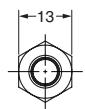
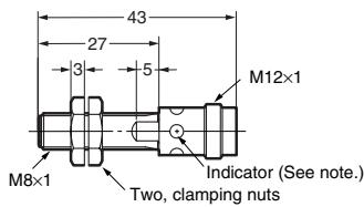
Note: Operation indicator (yellow LED, 4 × 90^ )
M12 Connector Models (Non-shielded)
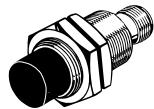
E2A-S08KN04-M1-□□
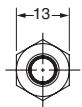
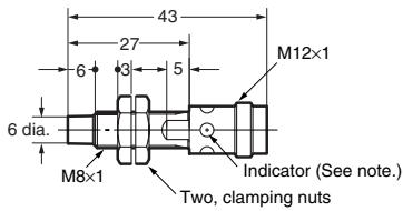
Note: Operation indicator (yellow LED, 4 × 90^ )
E2A-M12KS04-M1-□/E2A-S12KS04-M1-
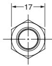
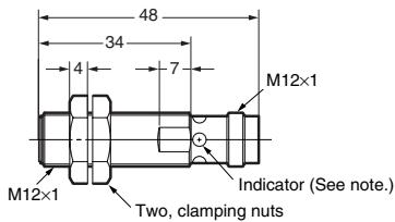
Note 1: Operation indicator (yellow LED, 4 × 90^ )
Note 2: for NO+NC (-B3 / -C3) models the total
length is 4 mm longer

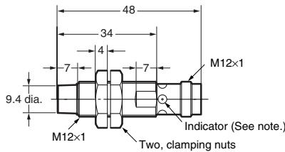
Note 1: Operation indicator (yellow LED, 4 × 90^ )
Note 2: for NO+NC (-B3 / -C3) models the total
length is 4mm longer
E2A-M18KS08-M1-□/E2A-S18KS08-M1-
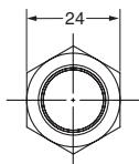
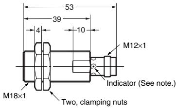
Note: Operation indicator (yellow LED, 4 × 90^ )
E2A-M18KN16-M1-□/E2A-S18KN16-M1-
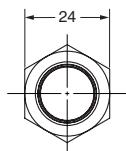
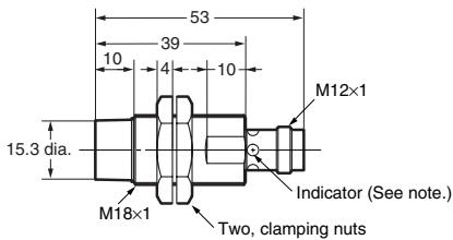
Note: Operation indicator (yellow LED, 4 × 90^ )
E2A-M30KS15-M1-□/E2A-S30KS15-M1-
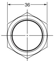
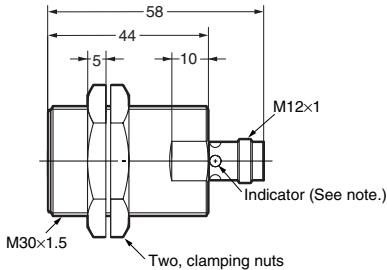
Note: Operation indicator (yellow LED, 4 × 90^ )
E2A-M30KN20-M1- /E2A-S30KN20-M1-
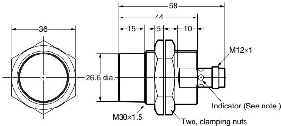
Note: Operation indicator (yellow LED, 4 × 90^ )
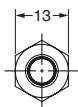
E2A-S08LS02-M1-□□

E2A-S08LN04-M1-□□
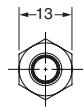
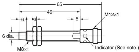
Note: Operation indicator (yellow LED, 4 × 90^ )
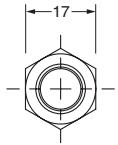
E2A-M12LS04-M1-□ E2A-S12LS04-M1-
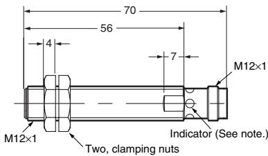
Note: Operation indicator (yellow LED, 4 × 90^ )
Note: Operation indicator (yellow LED, 4 × 90^ )
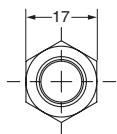
E2A-M12LN08-M1-□ E2A-S12LN08-M1-
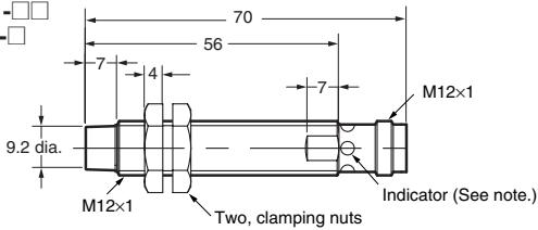
Note: Operation indicator (yellow LED, 4 × 90^ )
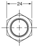
E2A-M18LS08-M1-□ E2A-S18LS08-M1-
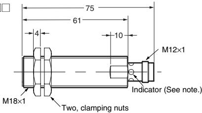
Note: Operation indicator (yellow LED, 4 × 90^ )
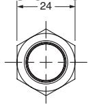
E2A-M18LN16-M1-□ E2A-S18LN16-M1-
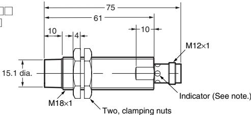
Note: Operation indicator (yellow LED, 4 × 90^ )
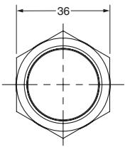
E2A-M30LS15-M1-□ E2A-S30LS15-M1-
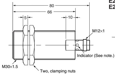
Note: Operation indicator (yellow LED, 4 × 90^ )
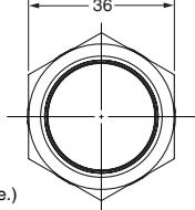
E2A-M30LN30-M1-□ E2A-S30LN30-M1-
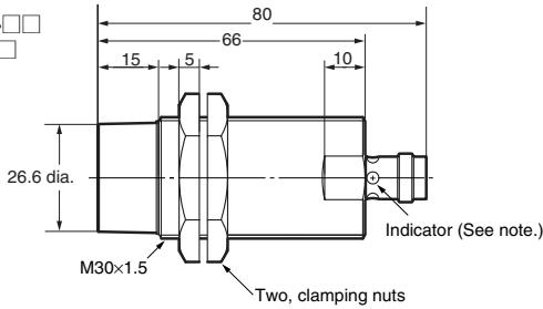
Note: Operation indicator (yellow LED, 4 × 90^ )
M8 Connector Models (Shielded)
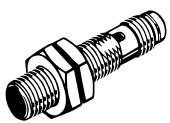
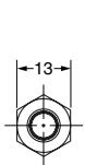
E2A-S08KS02-M5- /E2A-S08KS02-M3-
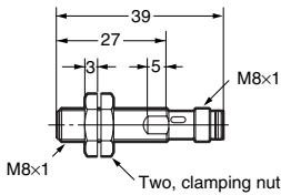
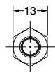
Note: Operation indicator (yellow LED, 4 × 90^ )
E2A-S08LS02-M5- /E2A-S08LS02-M3-
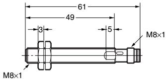
Note: Operation indicator (yellow LED, 4 × 90^ )
M8 Connector Models (Non-shielded)
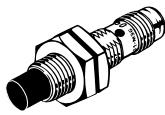

E2A-S08KN04-M5- /E2A-S08KN04-M3-
Note: Operation indicator (yellow LED, 4 × 90^ )
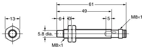
E2A-S08LN04-M5- /E2A-S08LN04-M3-
Note: Operation indicator (yellow LED, 4 × 90^ )
Note: Please contact your OMRON sales representative for dimension drawings not listed here.
Precautions
Safety Precautions
Power Supply
Do not impose an excessive voltage on the E2A, otherwise it may be damaged. Do not impose AC current (100 to 240 VAC) on any DC model, otherwise it may be damaged.
Load Short-circuit
Do not short-circuit the load, or the E2A may be damaged.
The E2A's short-circuit protection function will be valid if the polarity of the supply voltage imposed is correct and within the rated voltage range.
Correct Use
Designing
Power Reset Time
The Proximity Sensor is ready to operate within 100 ms (160ms for NO+NC -B3 / -C3 types) after power is supplied. If power supplies are connected to the Proximity Sensor and load respectively, be sure to supply power to the Proximity Sensor before supplying power to the load.
Effects of Surrounding Metal
When mounting the E2A within a metal panel, ensure that the clearances given in the following table are maintained.
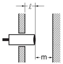
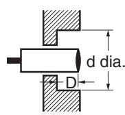
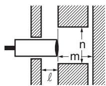
(Unit: mm)
| Type | Dimension | M8 | M12 | M18 | M30 | |
| Short barrel | Long barrel | |||||
| Shielded | I | 0 | 0 | 0 (See note 1.) | 0 (See note 2.) | |
| m | 4.5 | 12 | 24 | 45 | ||
| d | --- | --- | 27 | 45 | ||
| D | 0 | 0 | 1.5 | 4 | ||
| n | 12 | 18 | 27 | 45 | ||
| Non-shielded | I | 12 | 15 | 22 | 30 | 40 |
| m | 8 | 20 | 48 | 70 | 90 | |
| d | 24 | 40 | 70 | 90 | 120 | |
| D | 12 | 15 | 22 | 30 | 40 | |
| n | 24 | 40 | 70 | 90 | 120 | |
Note 1. In the case of using the supplied nuts.
If true flash mounting is necessary, apply a free zone of 1.5mm
2. In the case of using the supplied nuts.
If true flush mounting is necessary, apply a free zone of 4mm
If true flash mounting is necessary, apply a free zone of 1.5 mm.
2. In the case of using the supplied nuts. If true flush mounting is necessary, apply a free zone of 4 mm.
Wiring
Be sure to wire the E2A and load correctly, otherwise it may be damaged.
Connection with No Load
Be sure to insert loads when wiring. Make sure to connect a proper load to the E2A in operation, otherwise it may damage internal elements.
Do not expose the product to flammable or explosive gases.
Do not disassemble, repair, or modify the product.
Power OFF
The Proximity Sensor may output a pulse signal when it is turned OFF. Therefore, it is recommended that the load be turned OFF before turning OFF the Proximity Sensor.
Power Supply Transformer
When using a DC power supply, make sure that the DC power supply has an insulated transformer. Do not use a DC power supply with an auto-transformer.
Mutual Interference
When installing two or more Sensors face-to-face or side-by-side, ensure that the minimum distances given in the following table are maintained.
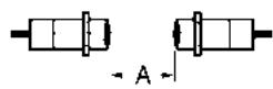
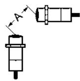
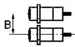
(Unit: mm)
| Type | Dimension | M8 | M12 | M18 | M30 | |
| Short barrel | Long barrel | |||||
| Shielded | A | 20 | 30 | 60 | 110 | |
| B | 15 | 20 | 35 | 70 | ||
| Non-shiel-DED | A | 80 | 120 | 200 | 300 | 300 |
| B | 60 | 100 | 120 | 200 | 300 | |
Wiring
High-tension Lines
Wiring through Metal Conduit:
If there is a power or high-tension line near the cable of the Proximity Sensor, wire the cable through an independent metal conduit to prevent against Proximity Sensor damage or malfunctioning.
Cable Extension
Standard cable length is less than 200m
The tractive force is 50 N.
Mounting
The Proximity Sensor must not be subjected to excessive shock with a hammer when it is installed, otherwise the Proximity Sensor may be damaged or lose its water-resistivity.
Do not tighten the nut with excessive force. A washer must be used with the nut.
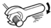
| Type | Torque | |
| M8 | Stainless steel type | 9 Nm |
| Brass type | 4 Nm | |
| M12 | 30 Nm | |
| M18 | 70 Nm | |
| M30 | 180 Nm | |
Maintenance and Inspection
Periodically perform the following checks to ensure stable operation of the Proximity Sensor over a long period of time.
- Check for mounting position, dislocation, looseness, or distortion of the Proximity Sensor and sensing objects.
- Check for loose wiring and connections, improper contacts, and line breakage.
- Check for attachment or accumulation of metal powder or dust.
- Check for abnormal temperature conditions and other environmental conditions.
- Check for proper lighting of indicators (for models with a set indicator.)
Never disassemble or repair the Sensor.
Environment
Water Resistivity
The Proximity Sensors are tested intensively on water resistance, but in order to ensure maximum performance and life expectancy avoid immersion in water and provide protection from rain or snow.
Operating Environment
Ensure storage and operation of the Proximity Sensor within the given specifications.
Inrush Current
A load that has a large inrush current (e.g., a lamp or motor) will damage the Proximity Sensor, in which case connect the load to the Proximity Sensor through a relay.
OMRON shall not be responsible for conformity with any standards, codes, or regulations that apply to the combination of the products in the customer's application or use of the products.
Take all necessary steps to determine the suitability of the product for the systems, machines, and equipment with which it will be used.
Product specifications and accessories may be changed at any time based on improvements and other reasons. Consult with your OMRON representative at any time to confirm actual specifications of purchased product.
ALL DIMENSIONS SHOWN ARE IN MILLIMETERS.
To convert millimeters into inches, multiply by 0.03937. To convert grams into ounces, multiply by 0.03527.
- Cylindrical Proximity Sensor
- E2A
- High quality for extra long life in daily use
- Ordering Information
- Model Number Legend
- E2A□-□□□□□-□-□□-□□
- Kind of connection
- Non-shielded Models
- DC 3-wire models
- Pre-wired Models (Non-shielded)
- M12 Connector Models (Shielded)
- E2A-S08KS02-M1-□□
- M12 Connector Models (Non-shielded)
- E2A-S08KN04-M1-□□
- E2A-M12KS04-M1-□/E2A-S12KS04-M1-
- E2A-M18KS08-M1-□/E2A-S18KS08-M1-
- E2A-M18KN16-M1-□/E2A-S18KN16-M1-
- E2A-M30KS15-M1-□/E2A-S30KS15-M1-
- E2A-M30KN20-M1- /E2A-S30KN20-M1-
- M8 Connector Models (Shielded)
- M8 Connector Models (Non-shielded)
- Precautions
- Safety Precautions
- Power Supply
- Load Short-circuit
- Correct Use
- Designing
- Power Reset Time
- Effects of Surrounding Metal
- Wiring
- Connection with No Load
- Do not expose the product to flammable or explosive gases.
- Power OFF
- Power Supply Transformer
- Mutual Interference
- High-tension Lines
- Cable Extension
- Mounting
- Maintenance and Inspection
- Environment
- Water Resistivity
- Operating Environment
- Inrush Current
Brand : OMRON
Model : E2A
Category : Proximity Sensors