
D4C - Proximity sensor OMRON - Free user manual and instructions
Find the device manual for free D4C OMRON in PDF.


| Type of product | Proximity sensor / Sealed limit switch |
| Brand | OMRON |
| Model | D4C |
| Protection degree | IP67 (dust-tight and temporary immersion) |
| Construction | Triple seal: nitrile rubber seal on plunger, diaphragm, nitrile rubber cap, resin-sealed cable entry |
| Housing material | Molded resin and stainless steel (plunger, roller) |
| Standard cable | S-FLEX VCTF, 2/3/5 m, oil-resistant and extreme temperature resistant |
| Rated voltages | 125/250 VAC, 8-250 VDC depending on model |
| Rated currents | 0.1 A to 5 A depending on model (resistive load) |
| Mechanical life | 10 million operations min. |
| Electrical life | 200,000 operations min. (5A/250VAC) |
| Ambient temperature | -10°C to 70°C (no frost) |
| Ambient humidity | 95% max. without condensation |
| Weight (with 3 m cable) | Approx. 360 g |
| Dimensions (pin plunger) | 49 mm (overall); mounting holes 5.1 mm Ø |
| Available actuators | Pin plunger, roller plunger, crossed roller plunger, beveled plunger, lever roller, rod lever, etc. |
| LED indicator | Optional (turns on or off during operation) |
| Certifications | UL, CSA, TÜV Rheinland (EN60947-5-1) |
| Insulation resistance | 100 MΩ min. (500 VDC) |
| Dielectric strength | 1000 VAC between terminals of same polarity; 1500 VAC between live parts and ground |
| Repairability | Spare parts available (head, actuator, mounting plate); standard screws |
| Maintenance | Clean with dry cloth; do not use solvents; check screw tightening |
Frequently Asked Questions - D4C OMRON
User questions about D4C OMRON
0 question about this device. Answer the ones you know or ask your own.
Ask a new question about this device
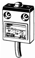
Download the instructions for your Proximity sensor in PDF format for free! Find your manual D4C - OMRON and take your electronic device back in hand. On this page are published all the documents necessary for the use of your device. D4C by OMRON.
USER MANUAL D4C OMRON
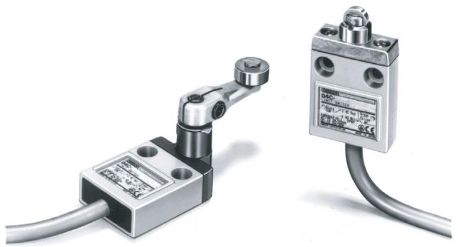
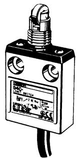
Sealed, Compact, and Slim-bodied Switch Offers Choice of Many Actuators
- Liquid- and dust-resistance conforms to IEC IP67 standard.
- Triple-sealed construction:
Plunger section sealed via nitrile rubber packing seal and diaphragm; switch section sealed via nitrile rubber cap; cable entrance sealed via encapsulating material. - Standard cable (S-FLEX VCTF) in 2-, 3-, or 5-meter lengths offers high flexibility with outstanding oil and extreme temperature resistance.
- Low temperature models are available.
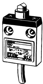
natural_image
Two metallic industrial sensors with attached cables, one showing a mechanical joint and the other a labeled sensor device (no visible text or symbols on the devices themselves)UL SA △CE
Model Number Structure
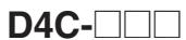
■ Model Number Legend
Standard Models
1 2 3
1. Rated Current
1: 5 A at 250 VAC, 4 A at 30 VDC
2: 5 A at 125 VAC (with LED indicator)
3: 4 A 30 VDC (with LED indicator)
4: 0.1 A at 125 VAC, 0.1 A at 30 VDC
5: 0.1 A at 125 VAC (with LED indicator)
6: 0.1 A at 30 VDC (with LED indicator)
2. Cable Specifications
2: VCTF oil-resistant cable (3 m)
3: VCTF oil-resistant cable (5 m)
4: VCTF (3 m)
5: VCTF (5 m)
6: SJT(O) (3 m)
7: SJT(O) (5 m)
8: VCTF oil-resistant cable (2 m)
9: VCTF (2 m)
3. Actuator
01: Pin plunger
02: Roller plunger
03: Crossroller plunger
10: Bevel plunger
20: Roller lever
24: Roller lever (high-sensitivity model)
31: Sealed pin plunger
32: Sealed roller plunger
33: Sealed crossroller
41: Panel mount pin plunger
42: Panel mount roller plunger
43: Panel mount crossroller plunger
50: Plastic rod
60: Center roller lever plunger
Note 1: Some combinations of the above may not be supported.
2: With standard models, the operation indicator turns OFF when the switch operates. If models with operation indicators that turn ON when the switch operates are required, add "-B" to the end of the model number.
Pre-wired Models (Use VCTF Oil-resistant Cable)

1. Operation Indicator Lamp
1: Without operation indicator
2: 1 A at 125 VAC (with operation indicator)
3: 1 A at 30 VDC (with operation indicator)
2. Actuator
01: Pin plunger
02: Roller plunger
31: Sealed plunger
32: Sealed roller plunger
24: Roller lever (high-sensitivity model)
3. Wiring Specifications
DK1EJ: Pre-wired models
(3 conductors: DC specification, NC wiring)
AK1EJ: Pre-wired models
(3 conductors: AC specification, NC wiring)
M1J: Connector models for ASI devices
(2 conductors: NO wiring)
Weather-resistant Models
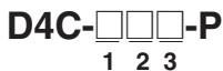
1. Rated Current
1: 5 A at 250 VAC, 4 A at 30 VDC
2: 5 A at 125 VAC (with LED indicator)
3: 4 A at 30 VDC (with LED indicator)
4: 0.1 A at 125 VAC, 0.1 A at 30 VDC
5: 0.1 A at 125 VAC (with LED indicator)
6: 0.1 A at 30 VDC (with LED indicator)
4. Cable length
03: 0.3 m
05: 0.5 m
10: 1 m
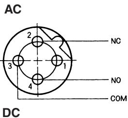
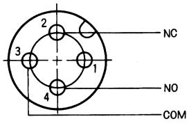
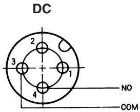
Wiring Specifications
| Internal switch | Connector |
| COM | 3 |
| NC | 2 |
| NO | 4 |
Note: Since the above wiring specifications are different from those for the D4CC, be careful not to mistake them.
2. Cable Specifications
2: VCTF oil-resistant cable (3 m)
3: VCTF oil-resistant cable (5 m)
3. Actuator
20: Roller lever
24: Roller lever (high-sensitivity model)
27: Variable roller lever
29: Variable rod lever
■ List of Models
Standard Models
| Actuator | Standard cable models | UL/CSA-approved cable models | ||||||||
| S-FLEX VCTF Cable* | VCTF Cable** | 5 A at 250 VAC without LED indicator | 5 A at 125 VAC with LED indicator (100 VAC) | |||||||
| SJT(O) Cable*** | ||||||||||
| EN60947-5-1 approved | UL/CSA approved | |||||||||
| 2 m | 3 m | 5 m | 2 m | 3 m | 5 m | 3 m | 5 m | 3 m | 5 m | |
| Pin[HDZT]plunger | D4C-□801 | D4C-□201 | D4C-□301 | D4C-□901 | D4C-□401 | D4C-□501 | D4C-1601 | D4C-1701 | D4C-2601 | D4C-2701 |
| Sealed[HDZT]plunger | D4C-□831 | D4C-□231 | D4C-□331 | D4C-□931 | D4C-□431 | D4C-□531 | D4C-1631 | D4C-1731 | D4C-2631 | D4C-2731 |
| Roller[OKGA]plunger | D4C-□802 | D4C-□202 | D4C-□302 | D4C-□902 | D4C-□402 | D4C-□502 | D4C-1602 | D4C-1702 | D4C-2602 | D4C-2702 |
| Sealed roller[ZXBD]plunger | D4C-□832 | D4C-□232 | D4C-□332 | D4C-□932 | D4C-□432 | D4C-□532 | D4C-1632 | D4C-1732 | D4C-2632 | D4C-2732 |
| Crossroller[ASY4]plunger | D4C-□803 | D4C-□203 | D4C-□303 | D4C-□903 | D4C-□403 | D4C-□503 | D4C-1603 | D4C-1703 | D4C-2603 | D4C-2703 |
| Sealedcrossroller[ZXTH]plunger | D4C-□833 | D4C-□233 | D4C-□333 | D4C-□933 | D4C-□433 | D4C-□533 | D4C-1633 | D4C-1733 | D4C-2633 | D4C-2733 |
| Bevel[ZXIX2]plunger | D4C-□810 | D4C-□210 | D4C-□310 | D4C-□910 | D4C-□410 | D4C-□510 | D4C-1610 | D4C-1710 | D4C-2610 | D4C-2710 |
| Coil[SEZW4]spring | D4C-□850 | D4C-□250 | D4C-□350 | D4C-□950 | D4C-□450 | D4C-□550 | D4C-1650 | D4C-1750 | D4C-2650 | D4C-2750 |
| Roller[HDZ4]lever | D4C-□820 | D4C-□220 | D4C-□320 | D4C-□920 | D4C-□420 | D4C-□520 | D4C-1620 | D4C-1720 | D4C-2620 | D4C-2720 |
| Roller lever(high-sensitivity model) | D4C-□824 | D4C-□224 | D4C-□324 | D4C-□924 | D4C-□424 | D4C-□524 | D4C-1624 | D4C-1724 | D4C-2624 | D4C-2724 |
| Panel mountpin plunger | D4C-□841 | D4C-□241 | D4C-□341 | D4C-□941 | D4C-□441 | D4C-□541 | D4C-1641 | D4C-1741 | D4C-2641 | D4C-2741 |
| Panel mountroller plunger | D4C-□842 | D4C-□242 | D4C-□342 | D4C-□942 | D4C-□442 | D4C-□542 | D4C-1642 | D4C-1742 | D4C-2642 | D4C-2742 |
| Panel mountcrossroller[XXZ7]plunger | D4C-□843 | D4C-□243 | D4C-□343 | D4C-□943 | D4C-□443 | D4C-□543 | D4C-1643 | D4C-1743 | D4C-2643 | D4C-2743 |
| Center roller lever plunger | D4C-□860 | D4C-□260 | D4C-□360 | D4C-□960 | D4C-□460 | D4C-□560 | D4C-1660 | D4C-1760 | D4C-2660 | D4C-2760 |
Note 1. Cold-resistant models are also available. Order these models with reference to the following example. D4C-1201 → D4C-1201-C
2. Models with viscosity-resistant oil specification (with an oil drain hole) are also available. Order these models with reference to the following example. Applicable only to the plunger models.
D4C-1202 → D4C-1202-M
3. Variable roller lever models are also available.
* Oil-resistant vinyl cabtire cables.
** Ordinary vinyl cabtire cables.
*** Models with SJT(O) Cables (approved by UL and CSA standards) conform to UL and CSA standards.
Standard Models (Continued)
| Actuator | CENELEC cable models | ||||||
| EN60947-5-1 approved | |||||||
| 1 m | 2 m | 3 m | 5 m | ||||
| Pinplunger | D4C-1G01 1 M | D4C-1G01 2 M | D4C-1G01 3 M | D4C-1G01 5 M | |||
| Sealedplunger | D4C-1G31 1 M | D4C-1G31 2 M | D4C-1G31 3 M | D4C-1G31 5 M | |||
| Rollerplunger | D4C-1G02 1 M | D4C-1G02 2 M | D4C-1G02 3 M | D4C-1G02 5 M | |||
| Sealed rollerplunger | D4C-1G32 1 M | D4C-1G32 2 M | D4C-1G32 3 M | D4C-1G32 5 M | |||
| Crossrollerplunger | D4C-1G03 1 M | D4C-1G03 2 M | D4C-1G03 3 M | D4C-1G03 5 M | |||
| Sealedcrossrollerplunger | D4C-1G33 1 M | D4C-1G33 2 M | D4C-1G33 3 M | D4C-1G33 5 M | |||
| Bevelplunger | D4C-1G10 1 M | D4C-1G10 2 M | D4C-1G10 3 M | D4C-1G10 5 M | |||
| Coilspring | D4C-1G50 1 M | D4C-1G50 2 M | D4C-1G50 3 M | D4C-1G50 5 M | |||
| Rollerlever | D4C-1G20 1M | D4C-1G20 2 M | D4C-1G20 3 M | D4C-1G20 5 M | |||
| Roller lever(high-sensitivity model) | D4C-1G24 1 M | D4C-1G24 2 M | D4C-1G24 3 M | D4C-1G24 5 M | |||
| Panel mountpin plunger | D4C-1G41 1 M | D4C-1G41 2 M | D4C-1G41 3 M | D4C-1G41 5 M | |||
| Panel mountroller plunger | D4C-1G42 1 M | D4C-1G42 2 M | D4C-1G42 3 M | D4C-1G42 5 M | |||
| Panel mountcrossrollerplunger | D4C-1G43 1 M | D4C-1G43 2 M | D4C-1G43 3 M | D4C-1G43 5 M | |||
Pre-wired Models (Use VCTF Oil-resistant Cable)
| Actuator | 1 A at 125 VAC without operation indicator | 1 A at 125 VAC with operation indicator | 1 A at 30 VDC without operation indicator | 1 A at 30 VDC with operation indicator |
Pin plunger ^ | D4C-1001-AK1EJ | D4C-2001-AK1EJ | D4C-1001-DK1EJ | D4C-3001-DK1EJ |
| Roller plunger ^ | D4C-1002-AK1EJ | D4C-2002-AK1EJ | D4C-1002-DK1EJ | D4C-3002-DK1EJ |
| Sealed plunger ^ | D4C-1031-AK1EJ | D4C-2031-AK1EJ | D4C-1031-DK1EJ | D4C-3031-DK1EJ |
| Sealed roller plunger ^ | D4C-1032-AK1EJ | D4C-2032-AK1EJ | D4C-1032-DK1EJ | D4C-3032-DK1EJ |
| Roller lever (high-sensitivity model) | D4C-1024-AK1EJ | D4C-2024-AK1EJ | D4C-1024-DK1EJ | D4C-3024-DK1EJ |
Note 1. The □ contains the length of the cable.
For example: 30 cm → D4C-1001-AK1EJ03
2. M1 models are also available. Contact your OMRON sales representative for further information.
Weather-resistant Models
| Actuator | 5 A at 250 VAC4 A at 30 VDC without operation indicator | 0.1 A at 125 VAC0.1 A at 30 VDC without operation indicator | 5 A at 125 VAC with operation indicator | 4 A at 30 VDC with operation indicator | 0.1 A at 125 VAC with operation indicator | 0.1 A at 30 VDC with operation indicator | |
Roller lever  | 3 m | D4C-1220-P | D4C-4220-P | D4C-2220-P | D4C-3220-P | D4C-5220-P | D4C-6220-P |
| 5 m | D4C-1320-P | D4C-4320-P | D4C-2320-P | D4C-3320-P | D4C-5320-P | D4C-6320-P | |
Roller lever (high-sensitivity model)  | 3 m | D4C-1224-P | D4C-4224-P | D4C-2224-P | D4C-3224-P | D4C-5224-P | D4C-6224-P |
| 5 m | D4C-1324-P | D4C-4324-P | D4C-2324-P | D4C-3324-P | D4C-5324-P | D4C-6324-P | |
Variable roller lever 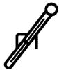 | 3 m | D4C-1227-P | D4C-4227-P | D4C-2227-P | D4C-3227-P | D4C-5227-P | D4C-6227-P |
| 5 m | D4C-1327-P | D4C-4327-P | D4C-2327-P | D4C-3327-P | D4C-5327-P | D4C-6327-P | |
Variable rol lever 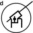 | 3 m | D4C-1229-P | D4C-4229-P | D4C-2229-P | D4C-3229-P | D4C-5229-P | D4C-6229-P |
| 5 m | D4C-1329-P | D4C-4329-P | D4C-2329-P | D4C-3329-P | D4C-5329-P | D4C-6329-P | |
Individual Parts (Head/Actuator)
| Actuator type | Head (with actuator) | Actuator |
| Pin plunger | D4C-0001 | - |
| Roller plunger | D4C-0002 | - |
| Crossroller plunger | D4C-0003 | - |
| Bevel plunger | D4C-0010 | - |
| Roller lever | D4C-0020 | WL-1A100 |
| Roller lever | D4C-0024 | WL-1A100 |
| Variable roller lever | D4C-0027 | HL-1HPA320 |
| Variable rod lever | D4C-0029 | HL-1HPA500 |
| Sealed pin plunger | D4C-0031 | - |
| Sealed roller plunger | D4C-0032 | - |
| Sealed crossroller plunger | D4C-0033 | - |
| Panel mount pin plunger | D4C-0041 | - |
| Panel mount roller plunger | D4C-0042 | - |
| Panel mount crossroller plunger | D4C-0043 | - |
| Plastic rod | D4C-0050 | - |
| Center roller lever | D4C-0060 | - |
Note 1: The model numbers for heads are of the form D4C-00□□, with the numbers in the squares indicating the type of actuator.
2: Actuators for plunger models, plastic rod models, and center roller lever models cannot be ordered individually. They must be ordered together with the head.
3: Consult your OMRON representative for details on cold-resistant specifications.
Mounting Plates
The WL model incorporated by equipment can be replaced with the D4C together with the Mounting Plate without changing the position of the dog or cam.
List of Replaceable Models
Contact your OMRON representative for the period required for delivery.
| WL model (Actuator) | D4C model (Actuator) | Plate |
| WLD/WL01D (Top plunger) | →D4C-□□01 (Plunger) | D4C-P001 |
| WLD2/WL01D2 (Top-roller plunger) | →D4C-□□02 (Roller plunger) | D4C-P002 |
| WLCA2/WL01CA2 (Roller lever) | →D4C-□□20 (Roller lever) | D4C-P020 |
Note: The WL01☐ is for micro loads.
Application Example
Note: The position of the dog remains unchanged.
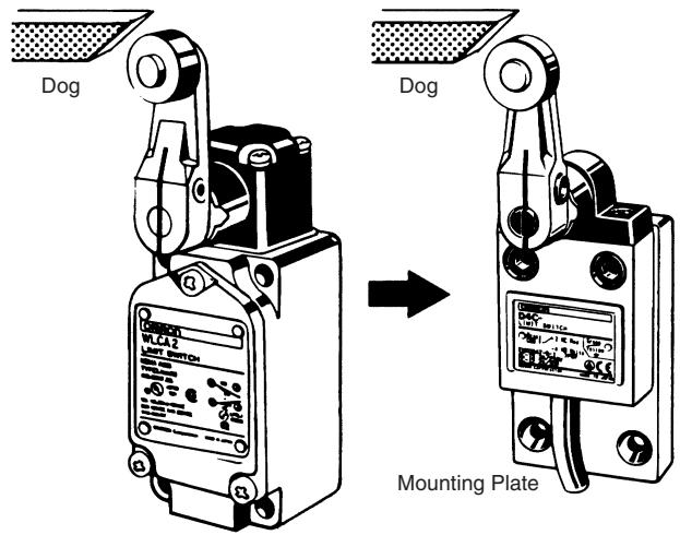
Remarks
There is no difference in mounting pitch between the Mounting Plate and the WL. The mounting depth of the D4C with the Mounting Plate attached is, however, shorter than that of the panel-mounted WL.
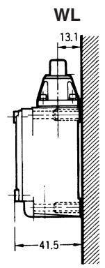
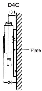
Specifications
■ Approved Standards
| Agency | Standard | File No. |
| TÜV Rheinland | EN60947-5-1 | R9451333 (see note 1)J9950970 (see note 2) |
| UL | UL508 | E76675 (see note 3) |
| CSA | CSA C22.2 No. 14 | LR45746 (see note 3) |
Note 1: Models with VCTF oil-resistant cables only.
2: Pre-wired models only.
3: SJT(0)-cable models only.
■ Approved Standard Ratings
General Ratings
| Model | Rated voltage | Non-inductive load | Inductive load | Inrush current | |||||||
| Resistive load | Lamp load | Inductive load | Motor load | ||||||||
| NC | NO | NC | NO | NC | NO | NC | NO | NC | NO | ||
| D4C-1□□□ | 125 VAC | 5 A | 5 A | 1.5 A | 0.7 A | 3 A | 3 A | 2.5 A | 1.3 A | 20 A max. | 10 A max. |
| 250 VAC | 5 A | 5 A | 1 A | 0.5 A | 2 A | 2 A | 1.5 A | 0.8 A | |||
| 8 VDC | 5 A | 5 A | 2 A | 2 A | 5 A | 4 A | 3 A | 3 A | |||
| 14 VDC | 5 A | 5 A | 2 A | 2 A | 4 A | 4 A | 3 A | 3 A | |||
| 30 VDC | 4 A | 4 A | 2 A | 2 A | 3 A | 3 A | 3 A | 3 A | |||
| 125 VDC | 0.4 A | 0.4 A | 0.05 A | 0.05 A | 0.4 A | 0.4 A | 0.05 A | 0.05 A | |||
| 250 VDC | 0.2 A | 0.2 A | 0.03 A | 0.03 A | 0.2 A | 0.2 A | 0.03 A | 0.03 A | |||
| D4C-2□□□ | 125 VAC | 5 A | 5 A | 1.5 A | 0.7 A | 3 A | 3 A | 2.5 A | 1.3 A | ||
| 125 VDC | 0.4 A | 0.4 A | 0.05 A | 0.05 A | 0.4 A | 0.4 A | 0.05 A | 0.05 A | |||
| D4C-3□□□ | 30 VDC | 4 A | 4 A | 2 A | 2 A | 3 A | 3 A | 3 A | 3 A | ||
| D4C-4□□□ | 125 VAC | 0.1 A | 0.1 A | --- | --- | ||||||
| 8 VDC | 0.1 A | 0.1 A | |||||||||
| 14 VDC | 0.1 A | 0.1 A | |||||||||
| 30 VDC | 0.1 A | 0.1 A | |||||||||
| D4C-5□□□ | 125 VAC | 0.1 A | 0.1 A | --- | --- | ||||||
| D4C-6□□□ | 30 VDC | 0.1 A | 0.1 A | --- | --- | ||||||
Ratings for Pre-wired Models
| Rated voltage | Non-inductive load | Inductive load | Inrush current | |||||||
| Resistive load | Lamp load | Inductive load | Motor load | |||||||
| NC | NO | NC | NO | NC | NO | NC | NO | NC | NO | |
| 125 VAC | 1 | 1 | 1 | 0.7 | 1 | 1 | 1 | 1 | 20 A max. | 10 A max. |
| 30 VDC | 1 | 1 | 1 | 1 | 1 | 1 | 1 | 1 | ||
Note 1. Inductive loads have a power factor of 0.4 min. (AC) and a time constant of 7 ms max. (DC).
2. Lamp loads have an inrush current of 10 times the steady-state current.
3. Motor loads have an inrush current of 6 times the steady-state current.
UL/CSA Approved Ratings
B300 (D4C-16□□, -17□□), B150 (D4C-26□□, -27□□)
NEMA B300 (D4C-16□□, -17□□)
| Rated voltage | Carry current | Current | Volt-amperes | ||
| Make | Break | Make | Break | ||
| 120 VAC | 5 A | 30 A | 3 A | 3,600 VA | 360 VA |
| 240 VAC | 15 A | 1.5 A | |||
NEMA B150 (D4C-26□□, -27□□)
| Rated voltage | Carry current | Current | Volt-amperes | ||
| Make | Break | Make | Break | ||
| 120 VAC | 5 A | 30 A | 3 A | 3,600 VA | 360 VA |
TÜV Rheinland Approved Ratings (EN60947-5-1)
| Model | Category and rating | I the |
| D4C-1□□□ | AC-15 2 A/250 VACDC-12 2 A/30 VDC | 5 A4 A |
| D4C-2□□□ | AC-15 2 A/125 VAC | 5 A |
| D4C-3□□□ | DC-12 2 A/30 VDC | 4 A |
| D4C-4□□□ | AC-14 0.1 A/125 VACDC-12 0.1 A/30 VDC | 0.5 A0.5 A |
| D4C-5□□□ | AC-14 0.1 A/125 VAC | 0.5 A |
| D4C-6□□□ | DC-12 0.1 A/30 VDC | 0.5 A |
Applicable Load Range
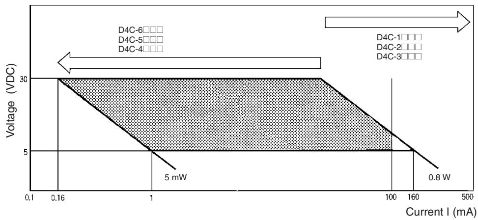
line
| Current I (mA) | Voltage (VDC) | | -------------- | ------------- | | 0.16 | 30 | | 1 | 5 | | 100 | 5 | | 160 | 5 | | 500 | 5 |■ Characteristics
| Degree of protection | IP67 |
| Durability (see note 2) | Mechanical: 10,000,000 operations min.Electrical: 200,000 operations min. (5A at 250 VAC, resistive load) |
| Operating speed | 0.1 mm to 0.5 m/s (in case of plunger)1 mm to 1 m/s (in case of roller lever) |
| Operating frequency | Mechanical: 120 operations/minElectrical: 30 operations/min |
| Rated frequency | 50/60 Hz |
| Insulation resistance | 100 MΩ min. (at 500 VDC) |
| Contact resistance (initial) | 250 mΩ max. (initial value with 2-m VCTF cable)300 mΩ max. (initial value with 3-m VCTF cable)400 mΩ max. (initial value with 5-m VCTF cable) |
| Dielectric strength | 1,000 VAC, 50/60 Hz for 1 min between terminals of the same polarity1,500 VAC, 50/60 Hz for 1 min between current-carrying metal part and ground, and between each terminal and non-current-carrying metal part, Uimp: 2.5 kV (EN60947-5-1) |
| Rated insulation voltage (Ui) | 300 V (EN60947-5-1) |
| Switching overvoltage | 1,000 VAC, 300 VDC max. (EN60947-5-1) |
| Pollution degree (operating environment) | 3 (IEC60947-5-1) |
| Short-circuit protective device (SCPD) | 10 A fuse type gG (IEC269) |
| Conditional short-circuit current | 100 A (EN60947-5-1) |
| Conventional enclosed thermal current (Ithe) | 5 A, 4 A, 0.5 A (EN60947-5-1) |
| Protection against electric shock | Class I (with grounding wire) |
| Vibration resistance | Malfunction: 10 to 55 Hz, 1.5-mm double amplitude |
| Shock resistance | Destruction: Approx. 1,000 m/s2 min.Malfunction: Approx. 500 m/s2 min. |
| Ambient temperature (see note) | Operating: -10°C to 70°C (with no icing) |
| Ambient humidity | Operating: 95% max. |
| Weight | With 3-m VCTF cable: 360 g; With 5-m VCTF cable: 540 g |
Note 1. The above figures are initial values.
2. The values are calculated at an operating temperature of 5^ C to 35^ C, and an operating humidity of 40% to 70%. Contact your OMRON sales representative for more detailed information on other operating environments.
■ Operating Characteristics
| Model | D4C-□□01D4C-□001-□K1EJ□ | D4C-□□31D4C-□031-□K1EJ□ | D4C-□□02D4C-□002-□K1EJ□ | D4C-□□32D4C-□032-□K1EJ□ | D4C-□□03 |
| OF max. | 11.77 N | 17.65 N | 11.77 N | 17.65 N | 11.77 N |
| RF min. | 4.41 N | 4.41 N | 4.41 N | 4.41 N | 4.41 N |
| PT max. | 1.8 mm | 1.8 mm | 1.8 mm | 1.8 mm | 1.8 mm |
| OT min. | 3 mm | 3 mm | 3 mm | 3 mm | 3 mm |
| MD max. | 0.2 mm | 0.2 mm | 0.2 mm | 0.2 mm | 0.2 mm |
| OP | 15.7±1 mm | 24.9±1 mm | 28.5±1 mm | 34.3±1 mm | 28.5±1 mm |
| TT | (5) mm | (5) mm | (5) mm | (5) mm | (5) mm |
| Model | D4C-□□33 | D4C-□□10 | D4C-□□50 | D4C-□□20D4C-□□27-P(see note 1)D4C-□□29-P(see note 1) | D4C-□□24D4C-□□24-PD4C-□024-□K1EJ□ |
| OF max. | 17.65 N | 11.77 N | 1.47 N | 5.69 N | 5.69 N |
| RF min. | 4.41 N | 4.41 N | --- | 1.47 N | 1.47 N |
| PT max. | 1.8 mm | 1.8 mm | 15° | 25° | 10±3° |
| OT min. | 3 mm | 3 mm | --- | 40° | 50° |
| MD max. | 0.2 mm | 0.2 mm | --- | 3° | 3° |
| OP | 34.3±1 mm | 28.5±1 mm | --- | --- | --- |
| TT | (5) mm | (5) mm | --- | (70°) | (70°) |
| Model | D4C-□□41 | D4C-□□42 | D4C-□□43 | D4C-□□60 |
| OF max. | 11.77 N | 11.77 N | 11.77 N | 6.67 N |
| RF min. | 4.41 N | 4.41 N | 4.41 N | 1.47 N |
| PT max. | 1.8 mm | 1.8 mm | 1.8 mm | 10 ± 3^ |
| OT min. | 3 mm | 3 mm | 3 mm | 50^ |
| MD max. | 0.2 mm | 0.2 mm | 0.2 mm | 3^ |
| OP | 31.2±1 mm | 36.8±1 mm | 36.8 mm | --- |
| TT | (5) mm | (5) mm | (5) mm | --- |
Note 1. The values given for D4C-□□27-P and D4C-□□29-P are for when the length of the lever is 38 mm.
2. The operating characteristics for M1J□ models are the same as those for □K1EJ□ models.
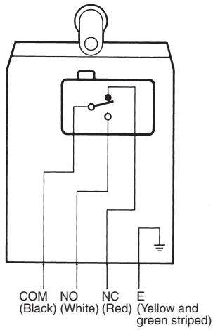
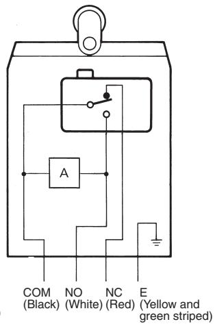
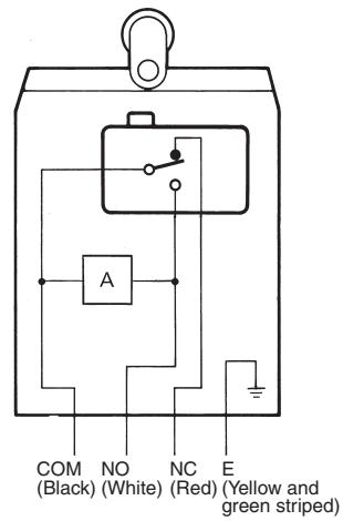
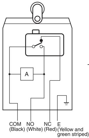
■ Contact Form
Standard Models / Weather-resistant Models
Without LED Indicator (S-FLEX VCTF Cable)
With LED Indicator (S-FLEX VCTF Cable)
With LED Indicator (lights when operated)
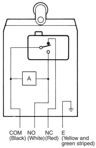
LED Indicator Circuits
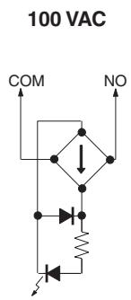
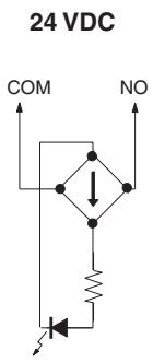
Yellow/green: VCTF resin cable
Green: VCTF
UL/CSA-approved cable SJT(0)
Note 1. "Lights when operated" means that when the actuator is turned or pushed and the Limit Switch contact leaves the NC side, the indicator lights.
- "Lights when not in operation" means that when the actuator is in the free position, the indicator is lit, and when the actuator is turned or pushed and the contact comes into contact with the NO side, the indicator turns OFF.
Wire Color
| Cable | Without LED | With LED | ||||||
| COM | NO | NC | E | COM | NO | NC | E | |
| VCTF | Black | White | Red | Green | Black | White | Red | Green |
| S-FLEX VCTF | Black | White | Red | Yellow/Green | Black | White | Red | Yellow/Green |
| SJT (O) | Black | Blue | Red | Green | Black | Blue | Red | Green |
| CENELEC CABLE | Blue | Black | Brown | Yellow/Green | Blue | Black | Brown | Yellow/Green |
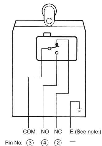
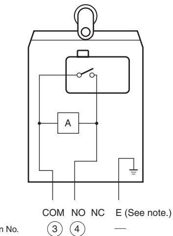
Pre-wired Models
Without LED Indicator
With LED Indicator (lights when not in operation)
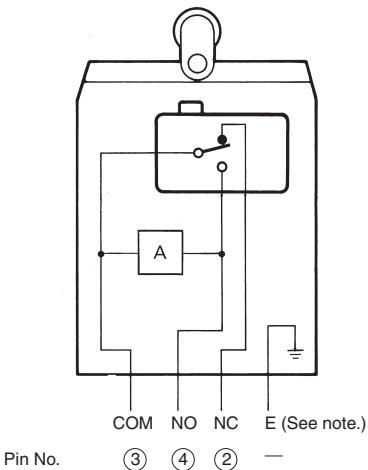
With LED Indicator (lights when operated)
Note: Not connected to the ground.
Yellow/green: VCTF resin cable
Green: VCTF
UL/CSA-approved cable SJT(0)
Note 1. "Lights when operated" means that when the actuator is turned or pushed and the Limit Switch contact leaves the NC side, the indicator lights.
2. "Lights when not in operation" means that when the actuator is in the free position, the indicator is lit, and when the actuator is turned or pushed and the contact comes into contact with the NO side, the indicator turns OFF.
Connector Models for ASI Devices
Without LED Indicator

With LED Indicator (lights when not in operation)
Note: Not connected to the ground.
With LED Indicator (lights when operated)
Yellow/green: VCTF resin cable
Green: VCTF
UL/CSA-approved cable SJT(0)
Note 1. "Lights when operated" means that when the actuator is turned or pushed and the Limit Switch contact leaves the NC side, the indicator lights.
2. "Lights when not in operation" means that when the actuator is in the free position, the indicator is lit, and when the actuator is turned or pushed and the contact comes into contact with the NO side, the indicator turns OFF.
■ Electrical Durability
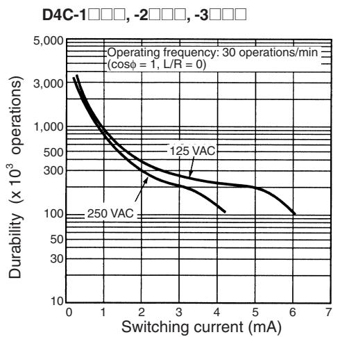
line
| Switching current (mA) | Durability (x 10³ operations) for 125 VAC | Durability (x 10³ operations) for 250 VAC | | ---------------------- | ------------------------------------------ | ------------------------------------------ | | 0 | 3000 | 3000 | | 2 | ~250 | ~200 | | 4 | ~150 | ~100 | | 6 | ~100 | ~80 |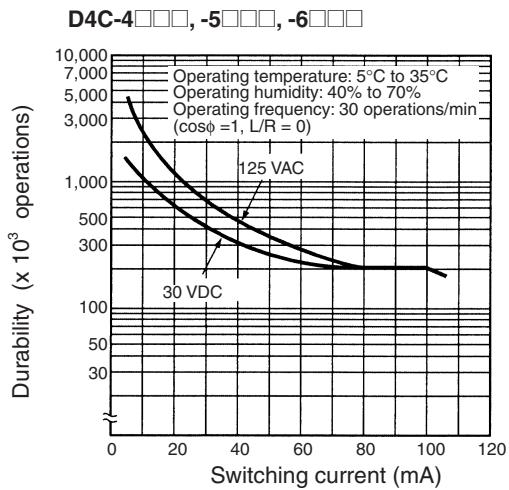
line
| Switching current (mA) | Durability (x 10³ operations) | | ---------------------- | ------------------------------ | | 0 | 5000 | | 20 | 3000 | | 40 | 125 | | 60 | ~250 | | 80 | ~250 | | 100 | ~250 |■ Leakage Current for LED-indicator Models
| Model | Voltage | Leakage current | Resistance |
| D4C-2□□□ | 125 VAC | 1.7 mA | 68 kΩ |
| D4C-3□□□ | 30 VDC | 1.7 mA | 15 kΩ |
| D4C-5□□□ | 125 VAC | 1.7 mA | 68 kΩ |
| D4C-6□□□ | 30 VDC | 1.7 mA | 15 kΩ |
Standard Models
Roller Lever Models Without Indicator
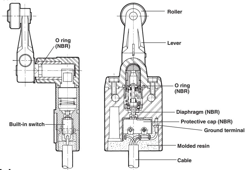
Weather-resistant Models
Roller Lever Models Without Indicator
Roller
The roller is made of self-lubricating sintered stainless steel and boasts high resistance to wear.
Shaft Section Seal
By fitting an O-ring to the rotary shaft and with an appropriate interference of the screws, high-sealing properties are maintained. The O-ring is made of silicone rubber and is resistant to temperature changes and adverse weather conditions.
Head-mounting
Screw
Diaphragm
The diaphragm is made of silicone rubber and is resistant to temperature changes and adverse weather conditions.
Cable
Vinyl cabtire cable and is resistant to adverse weather conditions.

natural_image
Cross-sectional technical drawing of a mechanical valve or pump assembly (no visible text or labels)Lever
The lever forged of anti-corrosive aluminium alloy features high corrosion resistances and outstanding ruggedness.
Roller Lever Setscrew
This screw is made of stainless steel and has high corrosion resistance.
Rotary Shaft
The shaft is made of stainless steel decreasing the likelihood of rusting.
Built-in Switch
Both standard load and microload models available.
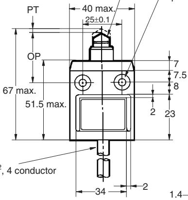
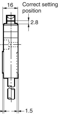
Note 1. All units are in millimeters unless otherwise indicated.
- Unless otherwise specified, a tolerance of ±0.4 mm applies to all dimensions.
Standard Models
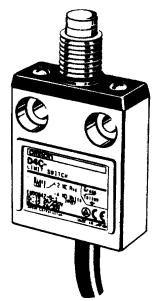
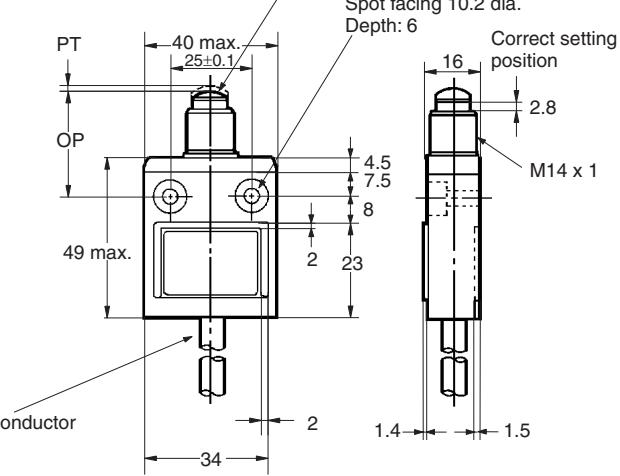
Pin Plunger
D4C-□□01
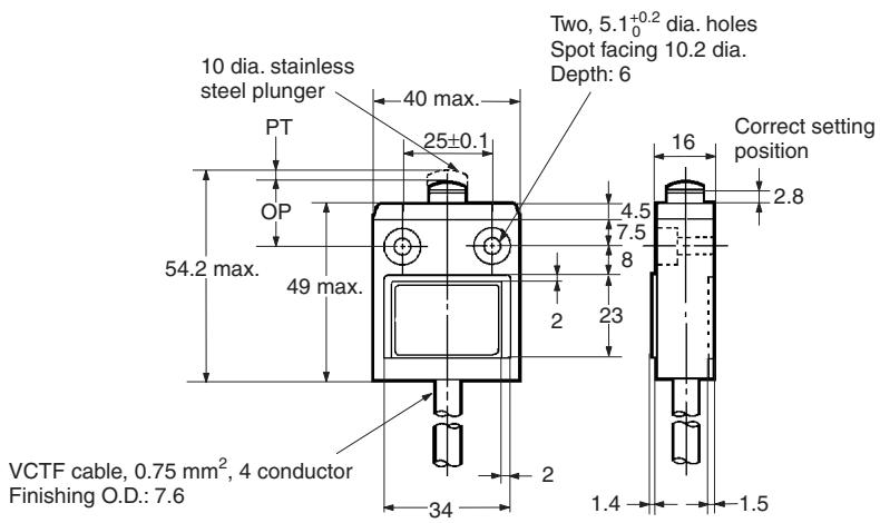
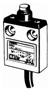
Sealed Plunger
D4C-□□31
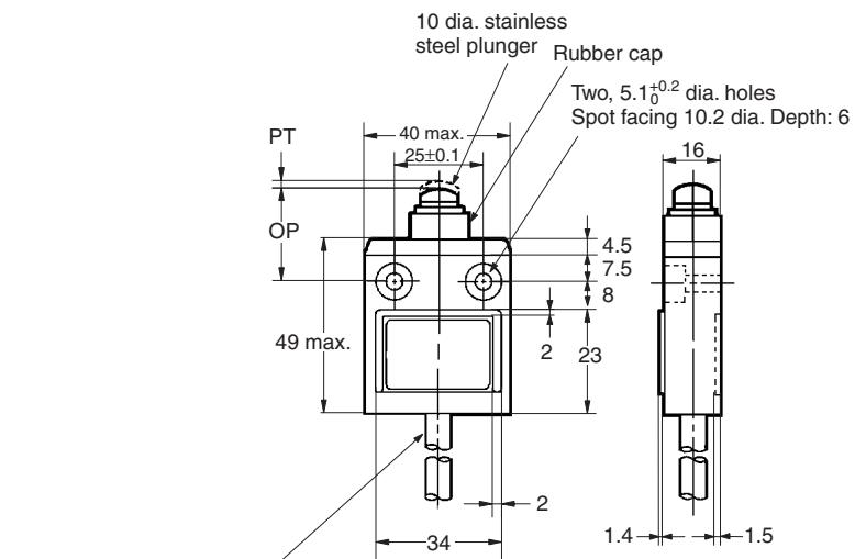
VCTF cable, 0.75 mm ^2 , 4 conductor Finishing O.D.: 7.6
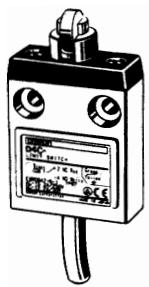
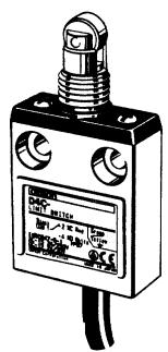
Roller Plunger
D4C-□□02
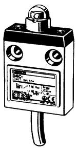
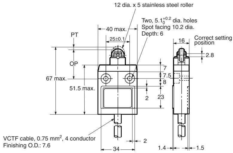
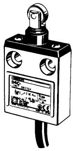
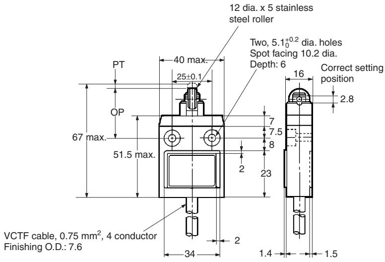
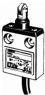
Sealed Roller Plunger
D4C-□□32
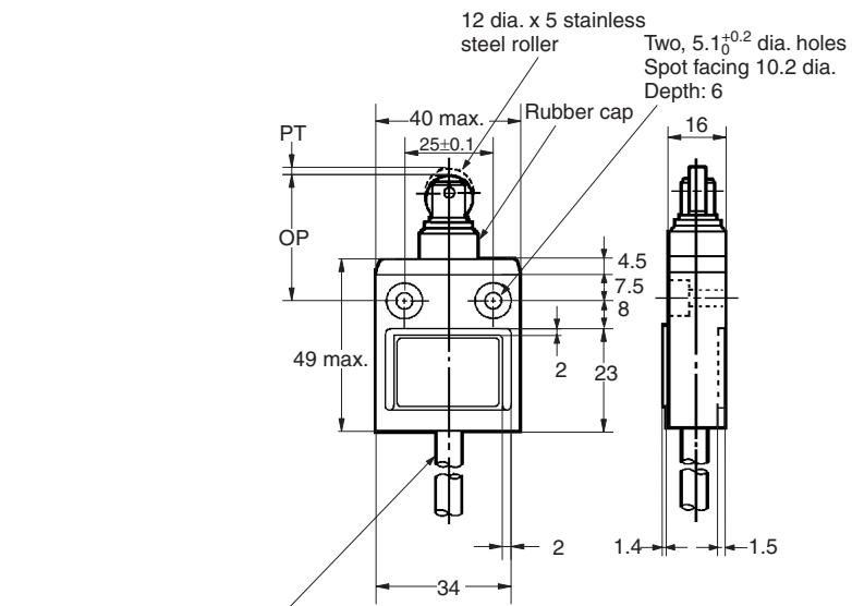
VCTF cable, 0.75 mm ^2 , 4 conductor Finishing O.D.: 7.6
Crossroller Plunger
D4C-□□03
Sealed Crossroller Plunger
D4C-□□33
natural_image
Illustration of a mechanical control device with no visible text or symbols on the body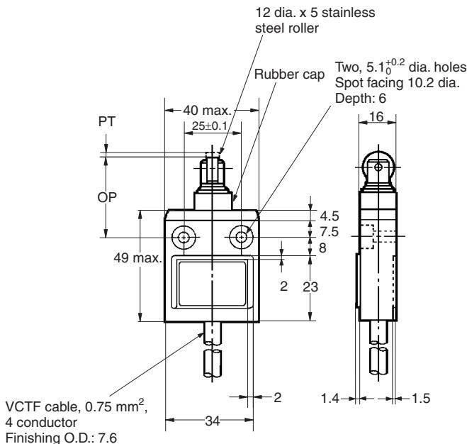
Bevel Plunger
D4C-□□10
VCTF cable, 0.75 mm ^2 , 4 conductor
Finishing O.D.: 7.6
Two, 5.1_0^+0.2 dia. holes
Spot facing 10.2 dia.
Depth: 6
10 dia. stainless
steel plunger
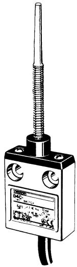
Coil Spring
D4C-□□50
natural_image
Technical illustration of a mechanical sensor or probe device with a threaded shaft and two ports (no visible text or symbols)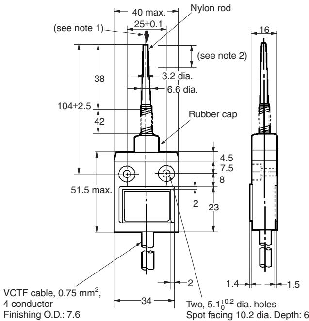
Note: 1. Operation is possible in any direction except in parallel to the axis ↓.
2. The ideal range for operation is between the tip of the rod and 1/3 of the length of the actuator.
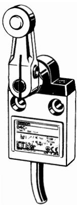
Roller Lever
D4C-□□20
D4C-□□20-P
VCTF cable, 0.75 mm ^2 , 4 conductor
Finishing O.D.: 7.6 (see note)
Note: S-FLEX VCTF Cables are used for weather-resistant models (D4C-P).
17.5 dia. x 7 stainless
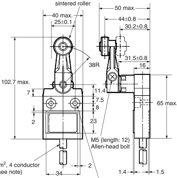
Two, 5.1_0^+0.2 dia. holes Spot facing 10.2 dia. Depth: 6
Roller Lever (High-Sensitivity Model)
D4C-□□24
D4C-□□24-P
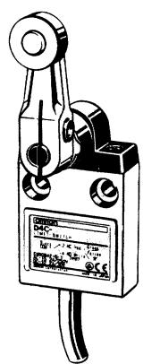
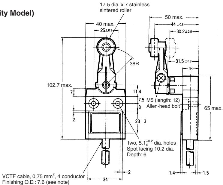
Note: S-FLEX VCTF Cables are used for weather-resistant models (D4C-P).
Center Roller Lever Plunger
D4C-□□60
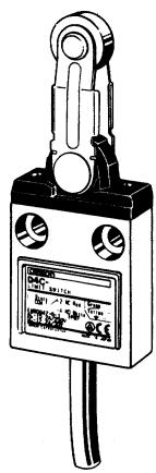
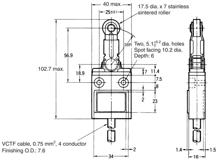
Panel Mount Pin Plunger
D4C-□□41
VCTF cable, 0.75 mm ^2 , 4 conductor Finishing O.D.: 7.6
10 dia. stainless steel plunger
Two, 5.1 ^+0.2_0 dia. holes
Spot facing 10.2 dia.
Depth: 6
Panel Mount Roller Plunger
D4C-□□42
natural_image
Illustration of a mechanical sensor or indicator device with no visible text or symbols on the body or background.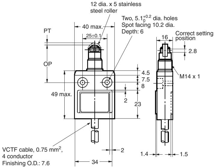
Panel Mount Crossroller Plunger
D4C-□□43
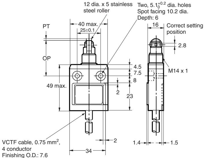
Note: Two nuts (thickness: 2.5; distance across: 17) are included with the D4C-□□41, D4C-□□42 and D4C-□□43.
Pre-wired Models
Pin Plunger

Roller Plunger
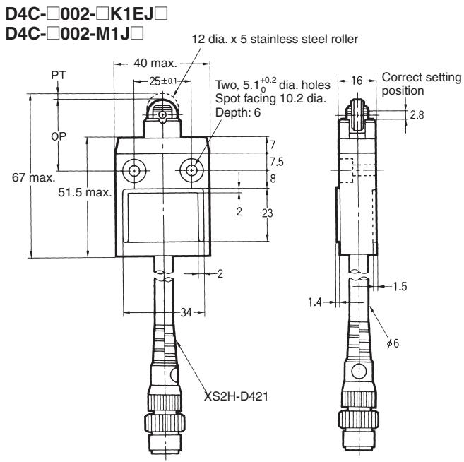
Sealed Pin Plunger
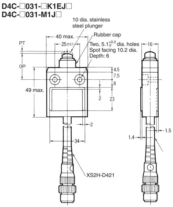
Sealed Roller Plunger
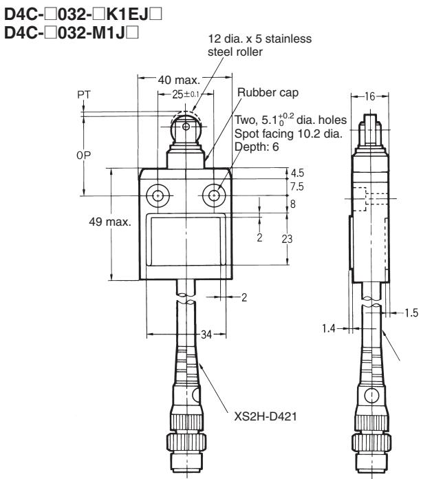
Roller Lever
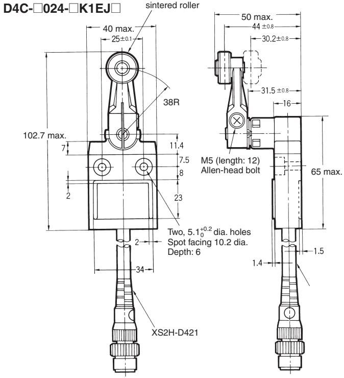
Weather-resistant Models
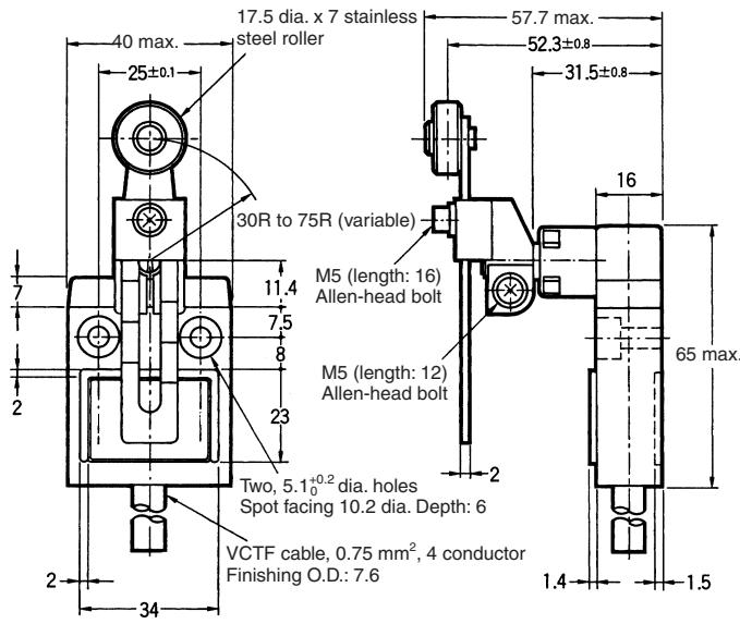
Adjustable Roller Lever
D4C-□□27-P
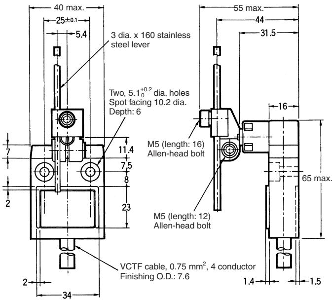
Adjustable Rod Lever
D4C-□□29-P
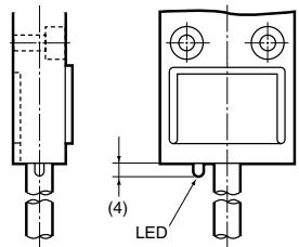
Models with LED Indicator
The dimensions of the LED indicator for models equipped with one are shown below.
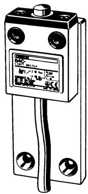
Special Mounting Plates (Plates are not provided with Limit Switches.)
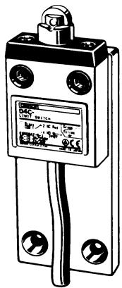
D4C-P001
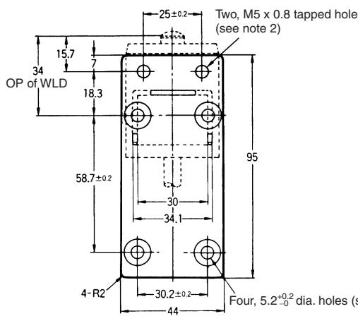
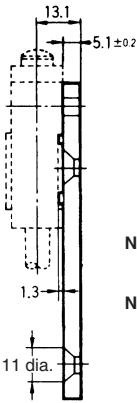
Note: Four, M5 x 0.8 hexagon pan-head bolts and two M5 x 0.8 Allen-head bolts are provided.
Note: 1. Tighten the 5.2^+0.2_-0 dia. holes with the M5 x 10 hexagon pan-head screws.
2. Insert the M5 Allen-head bolts into the M5 tapping holes to tighten the Mounting Plate securely.
D4C-P002
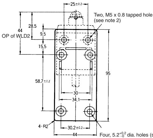
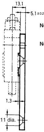
Note: Four, M5 x 0.8 hexagon pan-head bolts and two M5 x 0.8 Allen-head bolts are provided.
Note: 1. Tighten the 5.2^+0.2_-0 dia. holes with the M5 x 10 hexagon pan-head screws.
2. Insert the M5 Allen-head bolts into the M5 tapping holes to tighten the Mounting Plate securely.
D4C-P020
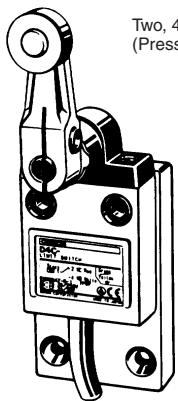
Two, 4.2_-0^+0.12 dia. positioning holes (Press-fit the spring pins.)
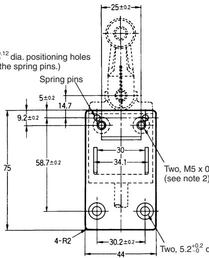
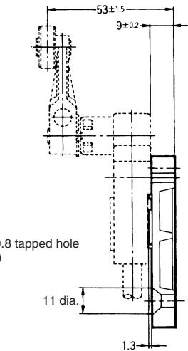
Note: Four, M5 x 0.8 hexagon pan-head bolts and two M5 x 0.8 Allen-head bolts are provided.
Note: 1. Tighten the 5.2^+0.2_-0 dia. holes with the M5 x 10 hexagon pan-head screws.
Four, M5 x 0.8 hexagon pan-head bolts,
two M5 x 0.8 Allen-head bolts are provided, and two 4 x 14 spring pins are provided.
2. Insert the M5 Allen-head bolts into the M5 tapping holes to tighten the Mounting Plate securely.
Note: Each dimension has a tolerance of ±0.4 mm unless otherwise specified.
■ Correct Use
Handling
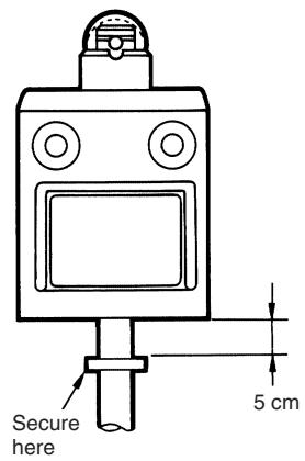
The bottom of the Switch at the cable outlet is resin-molded. Secure the cable at a point 5 cm from the Switch bottom to prevent exertion of excess force on the cable.
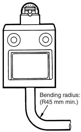
When bending the cable, provide a bending radius of 45 mm min. so as not to damage the cable insulation or sheath. Excessive bending may cause fire or leakage current.
Connections
Be sure to connect a fuse with a breaking current 1.5 to 2 times larger than the rated current to the Limit Switch in series in order to protect the Limit Switch from damage due to short-circuiting.
When using the Limit Switch for the EN ratings, use the gl or gG 10-A fuse.
Operation
Operation method, shapes of cam and dog, operating frequency, and overtravel have a significant effect on the service life and precision of a Limit Switch. For this reason, the dog angle must be 30^ max., the surface roughness of the dog must be 6.3S min. and hardness must be Hv400 to 500.
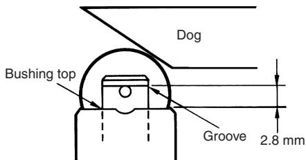
To allow the plunger-type actuator to travel properly, adjust the dog and cam to the proper setting positions. The proper position is where the plunger groove fits the bushing top.
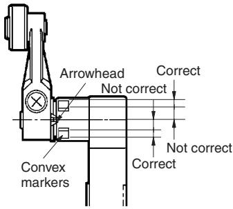
To allow the roller lever-type actuator to travel properly, adjust the dog and cam so that the arrow head is positioned between the two convex markers as shown below.
Mounting
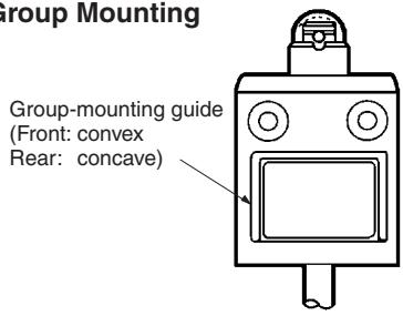
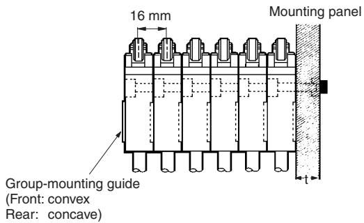
A maximum of 6 Switches may be group-mounted. In this case, pay attention to the mounting direction so that the convex part of the group-mounting guide on one Switch fits into the concave part of the guide on the other Switch as shown in the figure below. For group mounting, the mounting panel must have a thickness (t) of 6 mm min.
Group Mounting
If the mounting panel is warped or has protruding parts, a malfunction may result. Make sure that the mounting panel is not warped and has even surfaces.
Mounting Holes
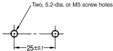
Use a Switch with a rubber cap when using the plunger type in an environment where malfunction is possible due to environmental conditions such as dust or cutting chips which may not allow resetting.
Do not expose the Switch to water exceeding 70^ C or use it in steam. When the D4C is used in a circuit of a device to be exported to Europe, classified as Overvoltage Class III as specified in IEC664, provide a contact protection circuit.
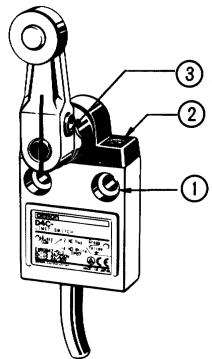
Tighten each screw to a torque according to the following table.
| No. | Type | Torque |
| 1 | M5 Allen-head bolt | 4.90 to 5.88 N·m |
| 2 | M3.5 head mounting screw | 0.78 to 0.88 N·m |
| 3 | M5 Allen-head bolt | 4.90 to 5.88 N·m |
Note: By removing the two screws from the head, the head direction can be rotated 180^ . After changing the head direction, re-tighten to the torque specified above. Be careful not to allow any foreign substance to enter the Switch.
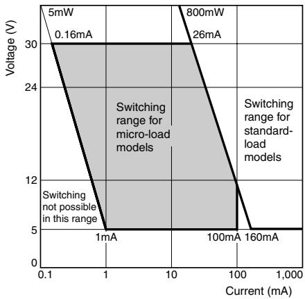
Micro-load Models (D4C-4, -5, -6)
Switching Range
Micro-load models can be used for switching in the range shown below.
ALL DIMENSIONS SHOWN ARE IN MILLIMETERS.
To convert millimeters into inches, multiply by 0.03937. To convert grams into ounces, multiply by 0.03527.
Cat. No. C032-E1-08
In the interest of product improvement, specifications are subject to change without notice.
- Sealed, Compact, and Slim-bodied Switch Offers Choice of Many Actuators
- Model Number Structure
- ■ Model Number Legend
- Standard Models
- Rated Current
- Cable Specifications
- Actuator
- Pre-wired Models (Use VCTF Oil-resistant Cable)
- Operation Indicator Lamp
- Actuator
- Wiring Specifications
- Weather-resistant Models
- Cable length
- ■ List of Models
- Mounting Plates
- List of Replaceable Models
- Application Example
- Remarks
- Specifications
- ■ Approved Standards
- ■ Approved Standard Ratings
- General Ratings
- UL/CSA Approved Ratings
- ■ Contact Form
- Standard Models / Weather-resistant Models
- Pre-wired Models
- Connector Models for ASI Devices
- Roller
- Shaft Section Seal
- Head-mounting
- Screw
- Diaphragm
- Cable
- Lever
- Roller Lever Setscrew
- Rotary Shaft
- Built-in Switch
- Models with LED Indicator
- Special Mounting Plates (Plates are not provided with Limit Switches.)
- ■ Correct Use
- Handling
- Connections
- Operation
- Mounting
- Micro-load Models (D4C-4, -5, -6)
- Switching Range
Brand : OMRON
Model : D4C
Category : Proximity sensor