
ULTRA TRIO PLUS 14 - Battery charger GRAUPNER - Free user manual and instructions
Find the device manual for free ULTRA TRIO PLUS 14 GRAUPNER in PDF.
User questions about ULTRA TRIO PLUS 14 GRAUPNER
0 question about this device. Answer the ones you know or ask your own.
Ask a new question about this device
Download the instructions for your Battery charger in PDF format for free! Find your manual ULTRA TRIO PLUS 14 - GRAUPNER and take your electronic device back in hand. On this page are published all the documents necessary for the use of your device. ULTRA TRIO PLUS 14 by GRAUPNER.
USER MANUAL ULTRA TRIO PLUS 14 GRAUPNER
Micro-processor controlled high-performance fast charger, discharger and battery conditioner for Ni-Cd / Ni-MH, LiPo / Lilo / LiMn / LiFe and lead-acid batteries
Max. charge current 5 A, max. discharge current 1 A
Balancer function for Li-batteries and NiMH/NiCd-batteries
| Chapter Contents | Page |
| 1. Introduction | 28 |
| 2.Warnings and safety notes, please read and observe! | 29 |
| 3. General notes on using the charger | 30 |
| 4. Recommended charge leads, polarity | 31 |
| 5. Controls, using the charger, starting the charge process | 31 |
| 6. Charge and discharge programs | 32 |
| 7. Program flowchart | 32 |
| 8. Selecting the charge program group | 33 |
| 9. Using the charger for the first time | 33 |
| 10. Starting the charge / discharge process | 34 |
| 11. Nickel-Cadmium (Ni-Cd) charge programs | 36 |
| 12. Nickel-Metal-Hydride (Ni-MH) charge programs | 38 |
| 13. Lithium-Ion / Lithium-Polymer / Li-Mn / LiFePO4- charge programs | 41 |
| 14. Lead-acid (Pb) charge programs | 44 |
| 15. Screen displays, cycle data display | 46 |
| 16. Monitor displays | 46 |
| 17. Error messages, warnings | 48 |
| 18. PC interface | 49 |
| 19. Cleaning and maintenance | 50 |
| 20. Notes on handling rechargeable batteries | 50 |
| 21. Specification, Environmental Protection Notes | 51 |
| 22. Environmental Protection Notes, | 52 |
| 1.Introduction | |
Please study these instructions, reading them completely and attentively, before using the unit for the first time. This will guarantee that you will be able to exploit all the facilities of your new battery charger. The warnings and safety notes are particularly important. Please store these instructions in a safe place, and be sure to pass them on to the new owner if you ever dispose of the charger.
In the ULTRA TRIO PLUS 14 you have acquired a mature product with an excellent performance. It incorporates the latest semi-conductor technology, controlled by a high-performance RISC micro-processor, to provide superior charging characteristics combined with simple operation and optimum reliability. These features can normally be expected only from much more expensive units. The ULTRA TRIO PLUS 14 represents a reliable method of charging sintered Nickel-Cadmium (NC, Ni-Cd) packs, Nickel-Metal-Hydride (Ni-MH) batteries, Lithium-Polymer (Li-Po), Lithium-Manganese (Li-Mn), Lithium-Ion (Li-Io) and LiFePO_4 (LiFe) batteries, and also lead-gel and lead-acid (Plumbum: Pb) batteries These sealed, gas-tight batteries have proved excellent for our purposes in RC models. They are mechanically robust, can be used in any attitude and are generally highly reliable. They require no special measures for storage apart from protecting the cells from becoming deep-discharged. The ULTRA TRIO PLUS 14 can also be used to discharge your batteries and balance the cells in a pack.
Note
It is important always to observe the charging instructions supplied by the battery manufacturer, and to keep to the recommended charge currents and times Do not fast-charge batteries unless the manufacturer states expressly that they are suitable for the high currents which flow during these processes. When charging new batteries you may also encounter problems with premature charge termination. Whenever you wish to use a new battery it therefore makes sense to carry out a series of monitored test charges, so that you can check that the automatic charge termination circuit works correctly and reliably with your packs, and charges them to full capacity.
2.Warnings and safety notes
- This product isn't designed for use by children under the age of 14, it isn't a toy!
- Protect the charger from dust, damp, rain, heat (e.g. direct sunshine) and vibration. It should only be operated in dry indoor conditions.
- The case slots serve to cool the charger, and must not be covered or enclosed; set up the charger with space round it, so that cooling air can circulate unhindered.
- The charger is designed to be powered by a 12 V DC car battery or power supply or 100~240V AC main socket only. It is not permissible to modify the charger in any way. Never use both inputs AC and DC at the same time!
- The charger and the battery to be charged should be set up on a heat-resistant, non-inflammable and non-conductive surface before use. Never place the charger directly on a car seat, carpet or similar. Keep all inflammable and volatile materials well away from the charging area. Provide good ventilation. Defective batteries can explode or burn!
- Connect the charger 12DC input directly to the car battery using the original cables and connectors supplied. The car's engine must be stopped all the time the charger is connected to the car's battery. Do not recharge the car battery at any time when the charger is connected to it.
- The charge output sockets and connecting leads must not be modified, and must not be interconnected in any way. There is a danger of short-circuit between the charge outputs and the vehicle's bodywork when the charger is connected to the car battery. The charge leads and connecting leads must not be coiled up when the charger is in use. Avoid short-circuiting the charge output or the model battery with the car bodywork. For this reason the charger must never be placed directly on the vehicle's bodywork.
- Never leave the charger running or connected to the car battery unsupervised.
- Only one battery may be connected to the unit for charging at any one time.
-
The following types of battery must not be connected to the charger:
-
Ni-Cd / Ni-MH batteries consisting of more than 14 cells, Lithium-Ion / Li-Mn / Lithium-Polymer / LiFePO_4 (LiFe) batteries of more than 6 cells, or lead-acid batteries with a nominal voltage of more than 12V.
- Batteries which require a different charge method from Ni-Cd, Ni-MH, Lithium or lead-acid types.
- Faulty or damaged cells or batteries.
- Batteries consisting of parallel-wired cells, or cells of different types.
- Batteries consisting of old and new cells, or cells of different makes.
- Non-rechargeable batteries (dry cells). Caution: explosion hazard!
- Batteries which are not expressly stated by the manufacturer to be suitable for the currents which this unit delivers during the charge process.
- Packs which are already fully charged or hot, or only partially discharged.
- Batteries or cells fitted with an integral charge circuit or charge termination circuit.
-
Batteries installed in a device, or which are electrically connected to other components.
-
To avoid short-circuits between the banana plugs fitted to the charge leads, please always connect the charge leads to the charger first, and only then to the battery to be charged. Reverse the sequence when disconnecting.
- As a basic rule always check that the charge quantity is approximately the same as you expected after the charger has indicated that the pack is fully charged. This is a simple method of detecting a problem reliably and in good time, should the charge process be terminated prematurely for any reason. The likelihood of premature termination varies according to many factors, but is at its highest with deep-discharged packs, low cell counts and particular cell types which are known to cause problems.
- We recommend that you carry out a series of test charges to satisfy yourself that the automatic termination circuit is working perfectly. This applies in particular when you are charging packs consisting of a small number of cells. If the cells feature has a poorly defined voltage peak, the charger may fail to detect the fully charged state.
- Before charging please check: have you selected the appropriate charge program for the battery? Have you set the correct charge or discharge current? Have you set the important cut-off voltage when charging Ni-Cd and Ni-MH packs? Are all connections firm, or is there an intermittent contact at any point in the circuit? Please bear in mind that it can be dangerous to fast-charge batteries. For example, if there is a brief interruption due to an intermittent contact, the result is inevitably a malfunction such as a restart of the charge process, which would result in the pack being massively overcharged.
3. General notes on using the charger
Charging batteries
When a battery is charged, a particular quantity of electrical energy is fed into it. The charge quantity is calculated by multiplying charge current by charge time. The maximum permissible charge current varies according to the battery type, and can be found in the information provided by the battery manufacturer.
It is only permissible to charge batteries at rates higher than the standard (slow) current if they are expressly stated to be rapid-charge capable. The STANDARD CHARGE CURRENT is 1/10 (one tenth) of the cells' nominal capacity (e.g. for a 1.7 Ah pack the standard charge current is 170mA ).
-
Connect the battery to be charged to the charger output sockets using a suitable charge lead (red = positive terminal, black = negative terminal).
-
Be sure to read the information provided by the battery manufacturer regarding charging methods, and observe the recommended charge currents and charge times. Do not attempt to fast-charge batteries unless they are expressly stated to be suitable for the high currents which this charger delivers.
-
Please bear in mind that new batteries do not reach their full capacity until they have undergone several charge / discharge cycles. You should also be aware that the charger may terminate the charge process prematurely when connected to new packs, and batteries which have been deep-discharged.
-
A Ni-Cd pack will normally be warm at the end of a rapid-charge process, but if you notice that one cell of the pack is much hotter than the others, this may well indicate a fault in that cell. Such packs could fail completely without warning, and should not be used again. Dispose of the battery safely, preferably taking it to a toxic waste disposal centre.
-
Ensure that all connectors and terminal clamps make good, sound contact. For example, if there is a brief interruption due to an intermittent contact, the result is inevitably a malfunction such as a restart of the charge process, which would result in the pack being massively overcharged.
-
A common cause of malfunctions is the use of unsuitable charge leads. Since the charger is incapable of detecting the difference between a pack's internal resistance, cable resistance and connector transfer resistance, the first requirement if the charger is to work perfectly is that the charge lead should be of adequate conductor cross-section and should be not be more than 30 cm long Good-quality connectors (gold-contact types) must be fitted to both ends.
- Charging transmitter batteries
A battery installed in a radio control transmitter can usually be recharged via the integral charge socket which is fitted to the transmitter itself. Transmitter charge sockets generally include a diode which prevents reverse current flow. This prevents damage to the transmitter electronics should the charger be connected with reverse polarity, or if a short-circuit occurs between the bare ends of the charge lead connectors. However, a transmitter battery protected in this way can only be charged by the ULTRA TRIO PLUS 14 if the diode is by-passed. Please read your transmitter operating instructions for information on how to do this. The stated maximum charge current for the transmitter battery must never be exceeded. To avoid possible damage to the internal transmitter components due to overheating and heat build-up, we recommend that the battery should be removed from the transmitter's battery compartment prior to charging. The transmitter must be set to "OFF" and left in that state for the whole period of the charge process.
Never switch a radio control transmitter on when it is still connected to the battery charger. The slightest interruption in the charge process may allow the charge voltage to rise to the point where it immediately ruins the transmitter.
Never attempt to carry out any battery discharge or battery maintenance programs via the transmitter's integral charge socket. The charge socket is not suitable for this purpose. When you set a particular current for charging, the charger only supplies that current if the value does not exceed the unit's technical capacity. If you set a charge current which the ULTRA TRIO PLUS 14 cannot deliver because it falls outside its technical limits, the unit automatically reduces the current to the maximum possible value. In this case the screen displays the charge current which is actually flowing, alternating with the warning message "MAX".
Liability exclusion
As manufacturers, we at GRAUPNER are not in a position to ensure that you observe the correct methods of operation when installing, using and maintaining this charger. For this reason we are obliged to deny all liability for loss, damage or costs which are incurred due to the incompetent or incorrect use and operation of our products, or which are connected with such operation in any way.
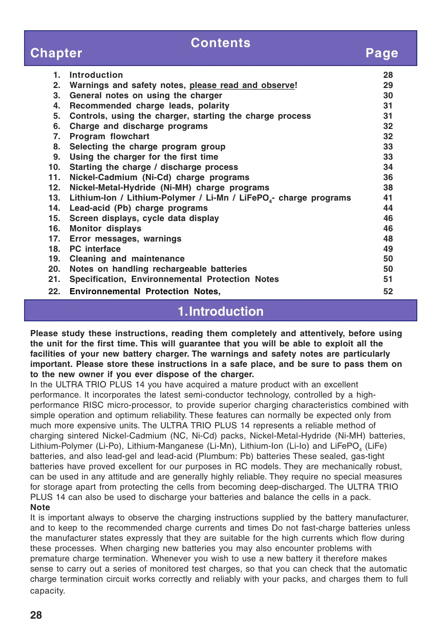
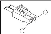
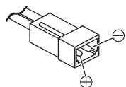
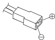
4. Recommended charge leads /polarity
The requirements made on rechargeable batteries vary greatly according to their particular application, and this in turn calls for different types of battery connector. Please note that connectors, connector names and polarities may vary from one manufacturer to another. For this reason we recommend that you always use genuine matching connectors of identical construction. The following charge leads are suitable for battery charging with this unit:
Japan
Order No. 3371
G2 (AMP/G2,5)
Order No. 3011
BEC
Order No. 3037
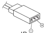
JR
Order No. 3021
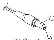
JR-Sender
Order No. 3022
Be sure to use genuine charge leads fitted with cable of adequate conductor cross-section.
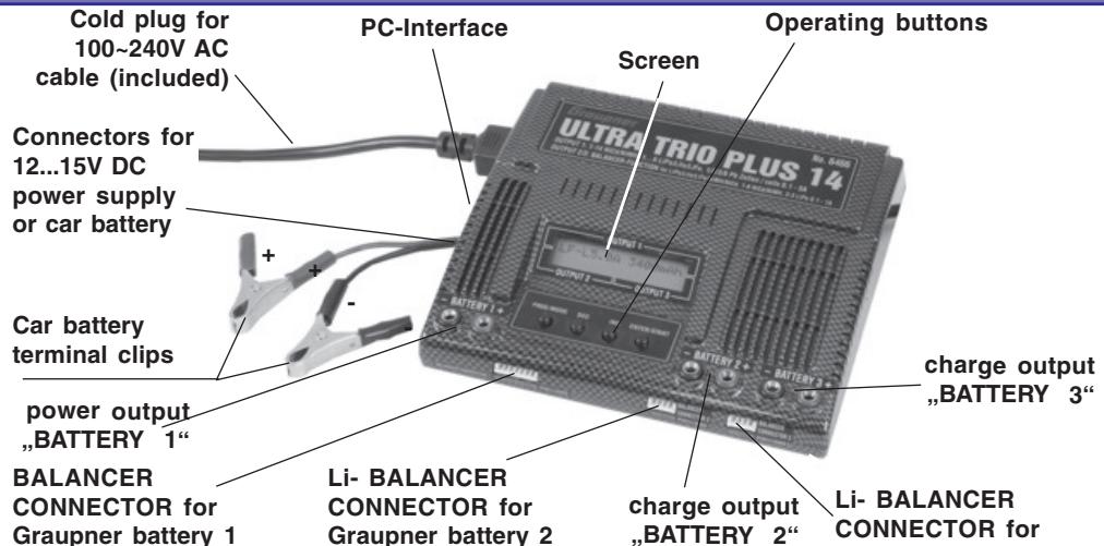
5. Charger controls / Using the charger / Starting the process
All the charger's functions are controlled by means of just four buttons. Graupner battery 3 The - / DEC and + / INC buttons are used to change the current and voltage values. The function of the other two buttons varies according to the presence or otherwise of a battery at the charge sockets:
| Operating button | Function | |
| No battery connected: | PROGRAMM/MODE | Select charge programs and sub-groups |
| PROGRAMM/MODE 2s. | Select the (charge) program group | |
| ENTER/START | Select next position of a discharge/cycle adjustment | |
| Battery connected: | PROGRAMM/MODE | Ends the charge process, stops the buzzer, |
| ENTER/START 2 sec. | Select next position of a discharge/cycle adjustment | |
| Starts the charge process |
6. Charge and discharge programs (Output 1)
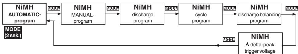
The various facilities of the charger are divided up into four program groups which you can select by holding the MODE button pressed in for two seconds. The sequence is shown in the flow chart below.
Ni-Cd battery programs: charging, conditioning, discharging to determine capacity or residual capacity, or to select cells.
Ni-MH battery programs: charging, conditioning, discharging to determine capacity or residual capacity, or to select cells.
LiPo / Lilo / LiFe battery programs: charging, discharging to determine capacity or residual capacity, or to select cells.
Lead-acid battery programs: charging, discharging to determine capacity or residual capacity, trickle charge for stand-by operation.
7. Program flowchart (Output 1)
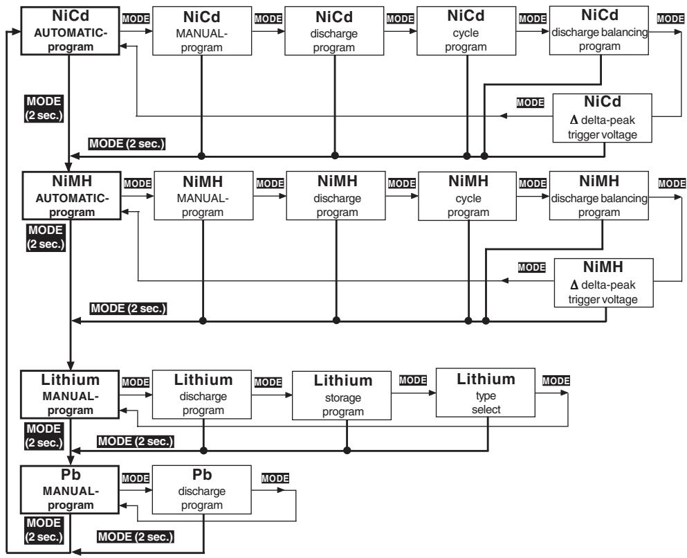
8. Selecting the charge program group (Output 1)

In the interests of clarity, the charge and set-up facilities of the ULTRA TRIO PLUS 14 are divided into four logical program groups.
A separate program group is provided for each of the different battery types: Nickel-Cadmium, Nickel-Metal-Hydride, Lithium-Ion / Lithium-Polymer / LiFePO _4 (LiFe) and Pb (lead-acid) batteries.
Switching programs:
- Changing from one program group to another is carried out using the MODE button, which must be held pressed in for about two seconds. A brief press on the MODE button makes changes within the program group.
9. Using the charger for the first time
When the INC and DEC buttons are pressed simultaneously and the ULTRA TRIO PLUS 14 is initially connected to a 12V DC car battery or power supply or a 100 240V AC mains socket, the unit goes to the language select menu, otherwise it runs through the information routine which provides you with a brief summary of the essential user settings. The charger's screen displays the following information.
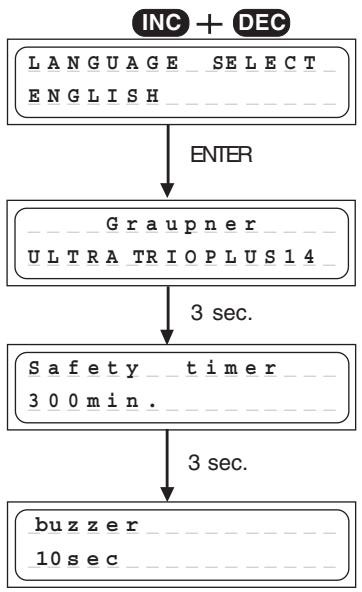
Press and hold the INC and DEC buttons simultaneously, then switch on the charger to get the language selection display. Select your language using the INC or DEC button and confirm with pressing the ENTER button.
The ULTRA TRIO PLUS 14's name appears on the screen.
After 3 sec. the adjustment of the safety timer (on or off) is displayed. For about 3 sec. the safety timer can be switched on or off by pushing the INC or DEC button.
The safety timer is always switched of for discharging and for Pb manual charge.
For all other charging programs, the safety timer will be 10...300min, if it's switched on.
After another 3 sec. the adjustment of the buzzer (on or off) can be changed by pushing the INC or DEC button. After another 3 sec. the charger is now ready for use, see 10..
10. Starting the charge / discharge process Output 1
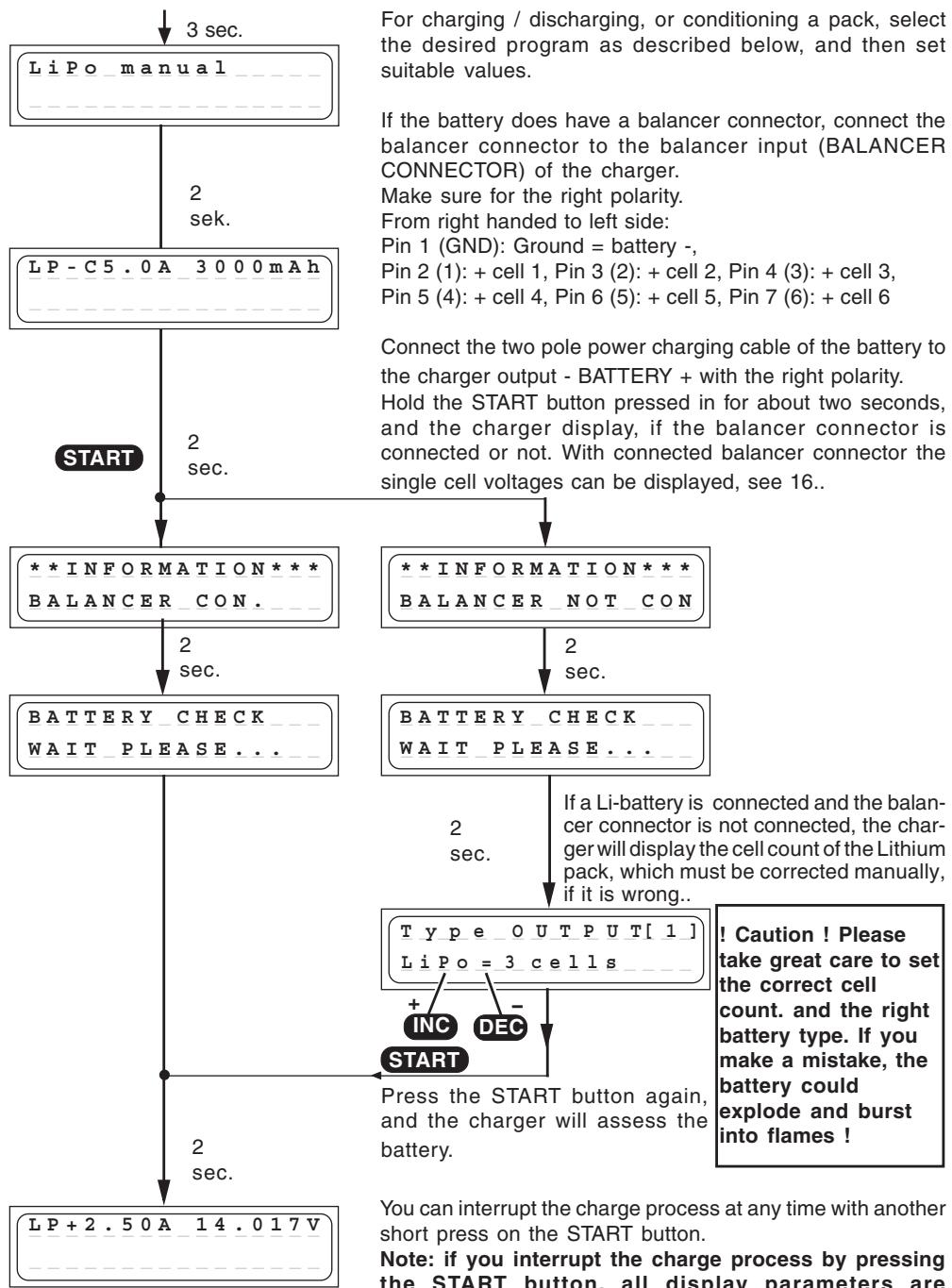
You can interrupt the charge process at any time with another short press on the START button.
Note: if you interrupt the charge process by pressing the START button, all display parameters are irretrievably erased.
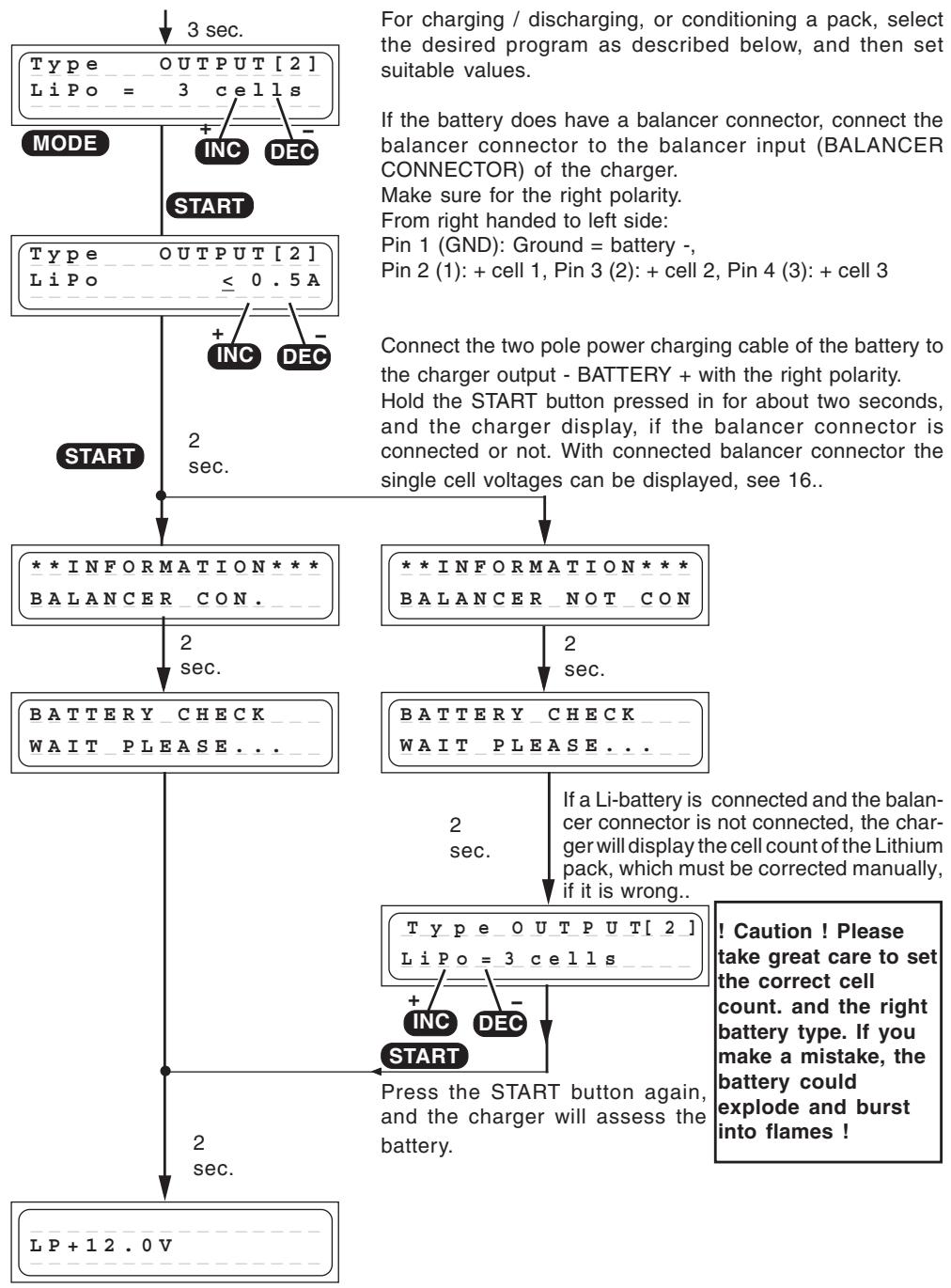
10. Starting the charge process Output 2 and 3
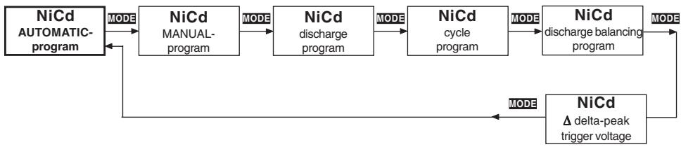
11. Ni-Cd programs (Output 1)
A set of convenient charge programs for recharging Nickel-Cadmium batteries, as commonly used for modelling purposes. When the charge / discharge program is finished, the screen displays the name of the charge program alternating with the message "END", together with the charge time, the last (dis-) charge current, the charged-in (discharged) capacity and the battery voltage, and continues to do so until you disconnect the battery. This information can often give you a useful indication about the Ni-Cd pack's charge characteristics and capacity, or warn you if the charger has incorrectly assessed the pack as being "full".
Ni-Cd automatic program

In this program the charger detects the type of Ni-Cd battery connected to it, and adjusts the charge current accordingly to avoid overcharging the pack.
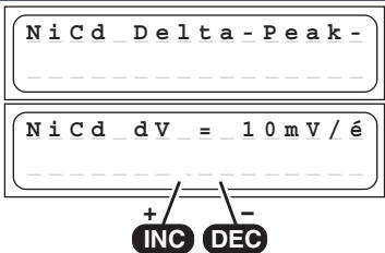
sec. The maximum charge current can be set before you connect the battery to be charged. This is done using the INC / DEC buttons; the range available is 0.1 A to 5 A, or no restriction. The charge process is terminated automatically in accordance with the values already set for "Ni-Cd Delta Peak cut-off voltage".
Ni-Cd manual program
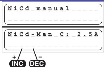
Select this program when you simply wish to recharge a battery using the set charge current.
2 You can adjust the charge current using the INC / DEC sec. buttons, but only before you connect the pack for charging. The range available is 0.1 A to 5 A.
The charge process is terminated automatically in accordance with the values already set for „Ni-Cd Delta Peak cut-off voltage".
Ni-Cd discharge program
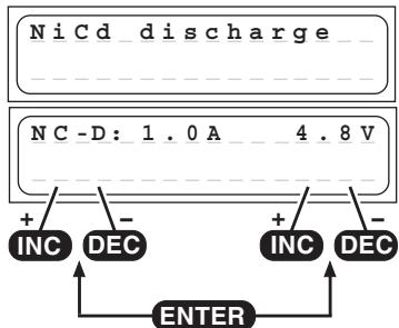
The typical purpose of this program is to determine the residual capacity of a transmitter, receiver or drive battery, or to discharge the pack to a defined level. In this program the charger discharges the pack using the set discharge current (0.1 ... 1.0 A, left of screen) until its voltage falls to the set final discharge voltage (0.1 ... 16.8 V, right of screen). The set final discharge voltage should be a value of around 0.9 ... 1,1 V per cell, in order to avoid the pack becoming deep-discharged. Deep-discharging a pack runs the risk of reversing individual cells, i.e. they exhibit reversed polarity.
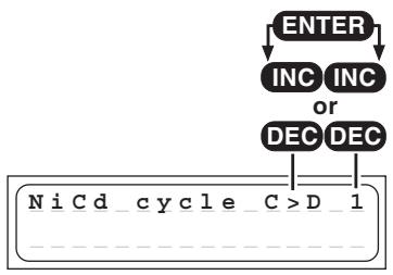
NiCd conditioning program
ENTER
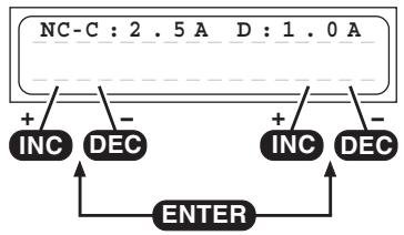
This program is designed to optimise the capacity of a battery, and balance the state of its component cells. At top right you can set use the INC or DEC buttons to determine whether the conditioning program is to start with a charge or discharge cycle. After this you set the number of cycles from 1 to 5 (e.g., if you set three cycles, the pack will be charged and discharged three times). The program discharges the battery using the set discharge current stated on the right of the screen (0.1 ... 1.0 A), and then recharges it using the charge current (0.1 ... 5.0 A) shown on the left of the screen. The charge process is terminated automatically in accordance with the values already set for „Ni-Cd Delta Peak cut-off voltage“. The discharge cut-off voltage is set in the Ni-Cd discharge program. The method of reading out the values for the actual cycle is described in the section „Screen displays“.
NiCd discharge balancing program
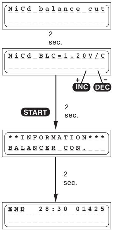
The discharge balancing program does discharge and balance up to 6 cells of a battery pack.
The final discharge voltage for the balancer can be set within the range 1.20 ... 1.30 V using the INC or DEC button.
The individual cells in a battery should be balanced before the pack is charged, to avoid the possibility of individual cells being overcharged during the charge process. A battery should always be balanced before being charged if it has been stored for a considerable period; connect the balancer plug to the charger to carry this out. It is also essential that the voltage of each cell in the pack should be higher than the set balancer final discharge voltage.
If you wish to obtain maximum battery capacity, the individual cells should be discharged to 1.20 V a few hours - but no longer than two hours - before the next charge process. If the voltage falls below 1.20 V, the battery cells lose capacity, so the pack must be charged to around 60% capacity before being stored for a protracted period.
The program discharges the battery pack at a rate of 50 mA ... 1.0 A. Cells with a higher cell voltage are discharged at an additional current of around 100 mA (balancing current). The charger terminates the discharge balance process once all the cells have reached the balancer final discharge voltage (+0.01 V).
NiCd-Delta-Peak (- Peak) trigger voltage
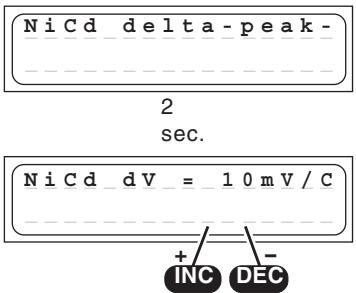
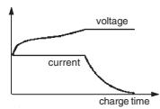
The automatic charge termination circuit (battery full detection) works on the proven Delta Peak principle (also known as the Delta-V process), which is already in use in millions of chargers.
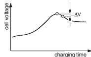
This process analyses the voltage peak of the charge curve, which indicates with great accuracy when the maximum charge capacity is reached. When the charge process is started the battery voltage initially rises continuously, but as the pack approaches full capacity it begins to heat up.
This in turn causes the battery voltage to fall slightly (Delta-V). The charger detects and assesses the voltage decline. It is possible to adjust the sensitivity, or trigger voltage (in mV per cell!) of the automatic cut-off circuit for Ni-Cd batteries. A practical range of values has proved to be 10 ... 30 mV / cell. Higher voltages often lead to overcharging of the battery, whereas a lower voltage tends to result in premature termination of the charge process. We recommend that you check the information supplied by your battery manufacturer, then carry out a series of test charges to establish the optimum value for your battery. Start with 10mV/cell to avoid overcharging the battery.
12. NIMh-programs (Output 1)
A set of convenient charge programs for recharging Nickel-Metal-Hydride batteries, as commonly used for modelling purposes. When the charge / discharge program is finished, the screen displays the name of the charge program alternating with the message „END“, together with the charge time, the last (dis-) charge current, the charged-in (discharged) capacity and the battery voltage, and continues to do so until you disconnect the battery. This information can often give you a useful indication about the Ni-MH pack's charge characteristics and capacity, or warn you if the charger has incorrectly assessed the pack as being „full".
NiMh automatic program
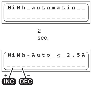
In this program the charger detects the type of Ni-MH battery connected to it, and adjusts the charge current accordingly to avoid overcharging the pack.
The maximum charge current can be set before you connect the battery to be charged.
Never use a maximum charge current higher as the value described in the battery instruction, never higher as 2C! Never charge transmitter batteries with more as 2A! f. e. a 4.2Ah battery should be limited to max. 4.2A.
This is done using the INC / DEC buttons; the range available is 0.1 A to 5 A, or no restriction.
The charge process is terminated automatically in accordance with the values already set for "Ni-MH Delta Peak cut-off voltage".
NiMh manual program
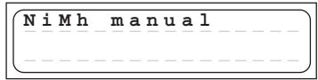
2 sec.
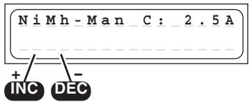
Select this program when you simply wish to recharge a battery using the set charge current. You can adjust the charge current using the INC / DEC buttons, but only before you connect the pack for charging. The range available is 0.1 A to 5 A.
Never use a maximum charge current higher as the value described in the battery instruction, never higher as 2C! Never charge transmitter batteries with more as 2A! f. e. a 4.2Ah battery should be limited to max. 4.2A. The charge process is terminated automatically in accordance with the values already set for „Ni-MH Delta Peak cut-off voltage".
NiMh discharge program
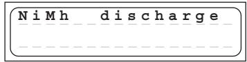
2 sec.
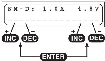
The typical purpose of this program is to determine the residual capacity of a transmitter, receiver or drive battery, or to discharge the pack to a defined level.
In this program the charger discharges the pack using the set discharge current (0.1 ... 1.0 A, left of screen) until its voltage falls to the set final discharge voltage (0.1 ... 16.8 V, right of screen).
The set final discharge voltage should be a value of around 1.0 ... 1.2 V per cell, in order to avoid the pack becoming deep-discharged. Deep-discharging a pack runs the risk of reversing individual cells, i.e. they exhibit reversed polarity.
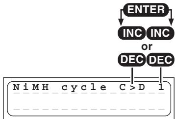
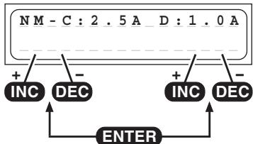
NiMh conditioning program
ENTER
This program is designed to optimise the capacity of a battery, and balance the state of its cells.
At top right you can use the INC or DEC button to determine whether the conditioning program is to start with a charge or discharge cycle. After this you set the number of cycles from 1 to 5 (e.g., if you set three cycles, the pack will be charged and discharged three times). The program discharges the battery using the set discharge current stated on the right of the screen (0.1 ... 1.0 A), and then recharges it using the charge current (0.1 ... 5.0 A) shown on the left of the screen. The charge process is terminated automatically in accordance with the values already set for „Ni-MH Delta Peak cut-off voltage". The discharge cut-off voltage is set in the Ni-MH discharge program. The method of reading out the values for the actual cycle is described in the section „Screen displays".
NiMh discharge balancing program
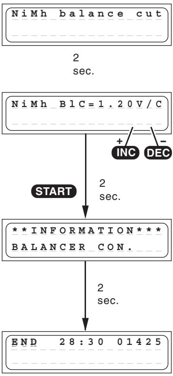
The discharge balancing program does discharge and balance up to 6 cells of a battery pack.
The final discharge voltage for the balancer can be set within the range 1.20 ... 1.30 V using the INC or DEC button.
The individual cells in a battery should be balanced before the pack is charged, to avoid the possibility of individual cells being overcharged during the charge process. A battery should always be balanced before being charged if it has been stored for a considerable period; connect the balancer plug to the charger to carry this out. It is also essential that the voltage of each cell in the pack should be higher than the set balancer final discharge voltage.
If you wish to obtain maximum battery capacity, the individual cells should be discharged to 1.20V a few hours - but no longer than two hours - before the next charge process. If the voltage falls below 1.20V , the battery cells lose capacity, so the pack must be charged to around 60% capacity before being stored for a protracted period.
The program discharges the battery pack at a rate of 50 mA ... 1.0 A. Cells with a higher cell voltage are discharged at an additional current of around 100 mA (balancing current). The charger terminates the discharge balance process once all the cells have reached the balancer final discharge voltage (+0.01 V).
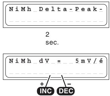
NiMh-Delta-Peak (- Peak) trigger voltage
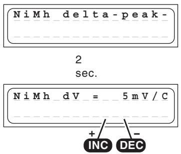
It is possible to adjust the trigger voltage (in mV per cell!) of the automatic termination circuit for Ni-MH batteries.
However, Ni-MH batteries have a less pronounced voltage drop than Ni-Cd cells, and a practical range has proved to be 5 ... 25 mV / cell. If the trigger voltage is set higher, there is a danger of overcharging the battery; if set lower, there is a danger of premature termination.
We recommend that you carry out a series of test charges to establish the ideal trigger value for your batteries. Start with 5mV / cell.
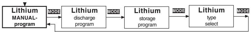
13. Lithium programs (Output 1)
These programs are only suitable for charging and discharging LiFePO_4 batteries with a voltage of 3.3V / Cell, Lithium-Ion batteries with a voltage of 3.6V / cell, and Lithium-Polymer and Lithium-Manganese batteries with a voltage of 3.7V / cell. The outstanding feature of Lithium batteries is their much higher capacity compared to other battery types. However, this important advantage is offset by the need to adopt different handling strategies: they must be charged and discharged using specific methods, otherwise they will be damaged, and can be dangerous. The directions in these instructions must be observed at all times when handling these batteries. Specific information and safety notes will also be found in the battery manufacturer's technical information.
The fundamental rule is that Lithium-based batteries may ONLY be charged using special chargers, and the charge program must be set up correctly in terms of final charge voltage and capacity for the battery type in use. The charge process is fundamentally different to that required for Ni-Cd or Ni-MH batteries, and is termed a constant current / constant voltage method. The charge current required varies according to the battery capacity, and is set automatically by the charger. Lithium
batteries are usually charged at the 1C rate (1C charge rate = half capacity as charge current. Example: battery capacity 1500mAh : 1C charge current = 1500mA = 1.5A ).
Because some types can be charged with upt to 2C or 4C charging current, the charging current and the capacity of the battery must be set separately. When the battery on charge reaches the specific final voltage which is appropriate to the battery type, the charger automatically reduces the charge current in order to prevent the battery exceeding the final permissible voltage. If the battery manufacturer states a charge current lower than the 1C rate, then the capacity (charge current) must be reduced accordingly.
We recommend the use of the balancer connector, which ensures that your Lithium batteries are charged optimally, and therefore increases safety and their useful life.
Problems caused by mistreating batteries:
It is very dangerous to overcharge Lithium-iron batteries, as they tend to react by gassing, overheating and even exploding. If the final charge voltage of 3.6V / cell (LiFePO_4) , 4.1V / cell (Lithium-iron) or 4.2V / cell (Lithium-Polymer and Lithium-Manganese) is exceeded by more than 1% , the lithium ions in the cell start to change into metallic lithium. This material reacts very violently with the water in the electrolyte, and this can result in the cell exploding. On the other hand it is also important to avoid terminating the charge process before the final charge voltage is reached, since this reduces the effective capacity of the Lithium-iron cell markedly. Stopping the charge at just 0.1V under the threshold means a capacity loss of around 7% . Lithium batteries must not be deep-discharged, as this leads to a rapid loss of capacity. This effect is irreversible; it is absolutely vital to avoid discharging the batteries to below 2.5V / cell.
Caution: the cell type, cell capacity and cell count set on the charger must always be correct for the battery to be charged; if you make a mistake, the battery could explode and burn! Never connect a Lithium-based battery to the charger if it features an integral charge circuit! Always place your Lithium batteries on a non-flammable surface for charging.
Lithium manual program
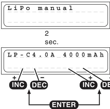
This program charges the battery using the capacity (charge current) which you set.
Before you initiate the actual program you must set the charging current (range 0.1A...5.0A, left of the screen) and the capacity of the pack (range 50...8000 mAh, right on the screen) using the INC / DEC buttons. Switch between the charge current and the capacity parameters by using the ENTER button.
If the charged capacity reaches 110% of the adjusted capacity, the charging process is stopped for safety reasons.
The charger automatically sets the charge current of 1C based on this information. When you connect the pack to the charger and start the charge process, the charge current starts at 0.00 A and slowly rises to the set limit. However, please do not be surprised if the charger does not reach the current you have set, because the charge program constantly monitors the battery voltage in order to prevent the pack inflating, provided that the voltage of the individual cells in the pack is the same. When the charger automatically reduces the charge current, the screen displays the message END, alternating with the reduced charge current.
Lithium discharge program
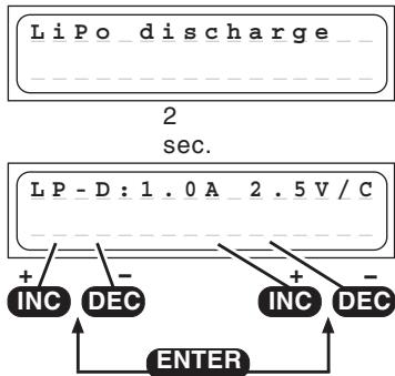
The purpose of this program is to determine the residual capacity of a Lithium pack which has not been fully discharged.
The program discharges the pack using the set discharge current (0.1 ... 1.0 A, left of screen) down to the set final discharge voltage (2.5 ... 3.7 V per cell, right of screen). It is not possible to set a final discharge voltage below 2.5 V per cell, otherwise the battery will suffer permanent damage.
Lithium storage program
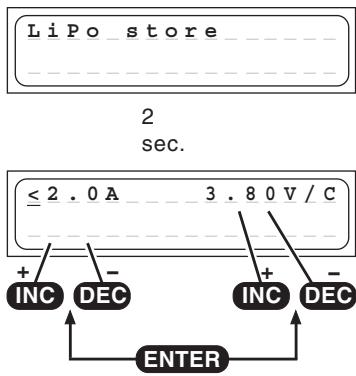
This program does charge or discharge the battery to the best storage voltage.
The program does charge or discharge the battery to the adjusted storage voltage, which is best for longer storage of a Li-battery.
Best store voltage:
LiPo: 3,8...3,9V/cell
Lilo: 3,7...3,8V/cell
LiFe: 3,3...3,4V/cell
Lithium cell count
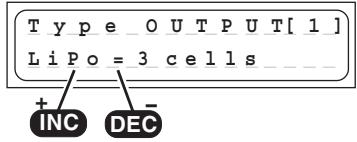
! Caution ! Please take great care to set the correct cell count and battery type. If you make a mistake, the battery could explode and burst into flames !
When you have connected the battery to the charger, hold the START button pressed in for about two seconds and the screen will display the cell count of the Lithium pack. If the pack contains 1 or 2 cells, the charger detects and sets the number of cells fully automatically. If the pack contains more than two cells, you may have to adjust the cell count manually using the INC / DEC buttons, as the automatic circuit is unable to detect more than three cells reliably. On the right-hand side you will see the voltage of the pack connected to the charger. Pressing the START button again initiates the charge process.
Lithium type select program
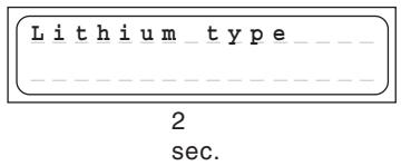
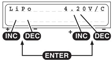
This is actually the most important set-up program for Lithium batteries. In the Select program you enter the battery type and battery capacity. It is vital to enter this information with the greatest care. Check it very thoroughly, as the charger derives all the other charge parameters from the settings you enter here. The battery type you select (LiPo, Lilo or LiFe) affects the charge termination voltage. If you find that a Lithium battery has unexpectedly been charged only to the 2/3 full mark, you have probably set the incorrect battery type at this point. Caution: if you set an incorrect value at this point, the battery may be damaged irreparably, and could even explode!
The final charge voltage can be adjusted in 0.01V steps. The max. charge voltage for LiPo is 4.2V, for Lilo 4.1V, for LiFe 3.6V. To store the batteries, adjust the charge voltage about 0.4V lower as the maximum charge voltage.
At charging/discharging the battery types will be displayed as followed:

14. Pb (lead-acid) programs (Output 1)
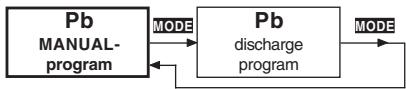
This program is designed for charging and discharging lead / sulphuric acid and lead / gel batteries with nominal voltages of exactly 2, 4, 6 and 12V (1, 2, 3 and 6 cells).
Caution: the charger will not recognize lead-acid batteries with other nominal voltages, and such batteries must not be connected to it.
Lead-acid batteries behave entirely differently to Ni-Cd and Ni-MH batteries. Lead-acid batteries can only deliver relatively low currents relative to their capacity, and similar restrictions very definitely apply to charging. Manufacturers usually state 14 to 16 hours for achieving nominal capacity when recharging at the normal charge current. The „normal“ charge current is defined as one tenth of the battery's nominal capacity. Example: battery capacity = 12 Ah → normal charge current = 1.2 A. In contrast to Ni-Cd and Ni-MH batteries, lead-acid chargers generally monitor the battery's voltage in order to determine when it is fully charged.
Caution: lead-acid batteries cannot and must not be fast-charged! Always select the charge current which the battery manufacturer recommends. Please also bear in mind that the nominal capacity (i.e. useful life) of a lead-acid battery is very quickly compromised by incorrect handling, including overcharging, repeated 100% discharges and, in particular, deep discharging. The magnitude of the charge / discharge currents is also crucial to the actual battery capacity which can be exploited, i.e. the higher the current, the lower the capacity which the battery can deliver.
The values selected in the user settings for charge termination delay and safety timer have no effect in the Pb charge programs.
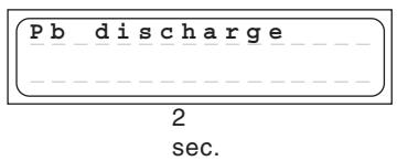
Pb manual program
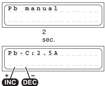
In this program you can set the maximum permissible charge current using the INC / DEC buttons, but only before you connect the lead-acid battery for charging. This setting only determines the top limit which the charger is permitted to feed to the battery.
If the battery manufacturer states a low maximum charge current, then it is important to limit the charge current to that value to avoid the charger setting a higher current if the battery appears to be willing to accept charge.
The battery can then be connected to the charger and the charge process started: the unit starts charging at 0.00 A and slowly raises the current until it reaches the set limit.
The charger constantly assesses the state of the battery during the charge process, and adjusts the charge current to suit its condition.
The charge program automatically determines the number of cells (cell count) in the battery by measuring its overall voltage.
Please do not be surprised if the charger does not deliver the charge current you have selected. The charge program constantly monitors the battery's voltage, and limits the current in order to prevent excessive gassing of the battery.
The ULTRA TRIO PLUS 14 now charges the battery using the maximum possible current until its voltage rises to around 2.3 to 2.35 Volts per cell. The charger then switches to a lower current to bring the battery gently up to full charge; this process reliably fills the battery "to the brim".
The unit cuts off the charge process automatically when the battery reaches a voltage of around 2.45 to 2.5 Volts per cell.
The effect of the automatic charge current adjustment system is to complete a full charge safely in much less than the usual 14 to 16 hours.
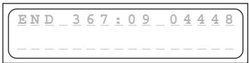
When the charge process is terminated, the charger emits audible tones for a certain period. At the same time the screen also displays the message "END".
Pb discharge program
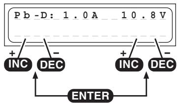
The typical purpose of this program is to determine the residual capacity of a drive battery.
In this program the charger discharges the pack using the set discharge current (0.1 ... 1.0 A, left of screen) until its voltage falls to the set final discharge voltage (1.7 ... 12.0 V, right of screen). To obtain a realistic capacity reading, i.e. one which actually reflects the battery's condition, the discharge current should be set
substantially below 1C (capacity of the battery = 2Ah = 2A ), and the final discharge voltage should be set to around 1.7V per cell.
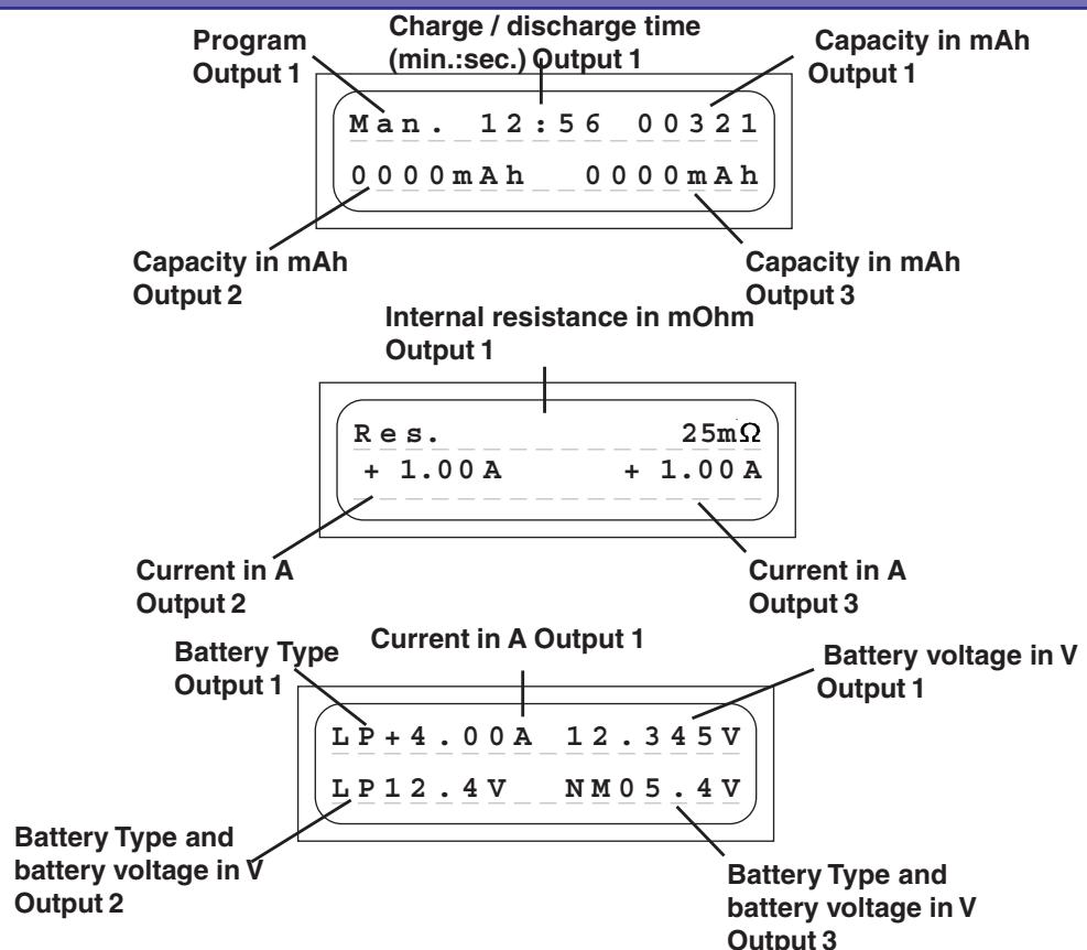
15. Screen displays
The two-line liquid-crystal screen displays in a clear form the important information generated during the charge / discharge process. The information remains visible on-screen until you disconnect the battery that is being charged. Once you connect another battery for charging, the previously displayed values are erased, and cannot be called up again.
16. On-screen monitor displays
The ULTRA TRIO PLUS 14 incorporates a wide range of protective and monitoring systems designed to check the charger's functions and monitor the state of its electronics. If any of the unit's critical limit values is exceeded, the charge process is switched off. Typical triggers would be excessive voltage, excessive temperature or a depleted car battery. If any of these problems should occur, the liquid crystal screen displays the cause of the error, and the buzzer sounds to alert you.
Measuring process
BATTERY_CHECK
WAITPLEASE...
When you hold the START button pressed in for about two seconds, the charger measures the battery connected to it. This message appears on the screen for one or two seconds before the charge process is initiated.
Ready message
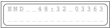
When a charge or discharge program comes to an end, the screen displays the message END, alternating with the program name. At the same time the integral buzzer sounds for a limited period.
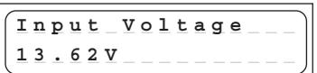
Input voltage and Battery resistance display
INC + DEC
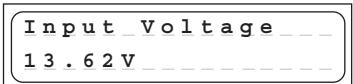
The current input voltage and battery resistance can be called up at any time by pressing the INC and DEC buttons simultaneously.
Change the display with INC or DEC button to input voltage, the battery resistance display and to the single cell voltages and backwards.
Displaying the Input voltage can be very useful if you are using your car's battery as energy source for charging.
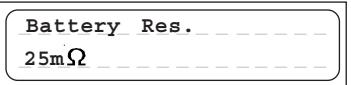
The battery resistance is measured after a few min after starting charging/discharging.
The battery resistance is one important value to determine the battery quality.
Press any button to return to the menu system.
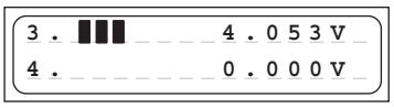
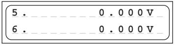
Display the voltage of the single cells
INC+DEC
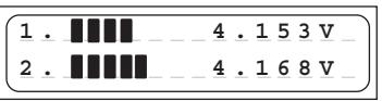
The current input voltage and battery resistance can be called up at any time by pressing the INC and DEC buttons simultaneously.
Change the display with INC or DEC button to input voltage, the battery resistance display and to the single cell voltages and backwards.
Displaying the single cell voltages is useful to check the single cell voltages 1-6 for output 1 and 1-3 for output 2 and 3.


17. Error messages and warnings
The ULTRAMAT 16 incorporates a wide range of protective and monitoring systems designed to check the charger's functions and monitor the state of its electronics. If any of the unit's limit values are exceeded, the charger responds accordingly: in some cases the unit's settings are automatically reduced (e.g. charge current / discharge current); in others the charge process is switched off (e.g. car battery almost flat).
The liquid crystal screen displays the cause of the error. Most error messages are self-explanatory, but you may find the following list useful when fault-finding. The warning message and the audible warning signal can be switched off by pressing the "ENTER" button.
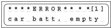
This warning message is displayed if the voltage of the car battery falls below the value set in the "Low voltage cutoff" section of the user settings (11.0 V).
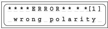
This warning message is displayed if a battery is connected to the unit's charge outputs with incorrect polarity.
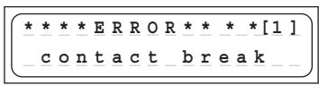
If the charger detects an interruption of the connection between battery and charger during a charge process, the screen displays this error message. If you see this error message when the charger is in use, it may indicate an intermittent contact.
Note: the same error message also appears if you deliberately interrupt the charge process, e.g. by disconnecting the charge lead.
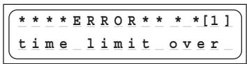
If the internal charge safety timer has elapsed, the current process is terminated for safety's sake. The safety timer is set permanently to 180 minutes for Ni-Cd / Ni-MH batteries. For Lithium batteries the set period is 180 minutes. The timer is disabled when a lead-acid battery is being charged. These settings are fixed, and cannot be altered. Possible causes: charge current too low: battery cannot be fully charged; charge leads too thin and / or too long - charge current cannot rise high enough: battery capacity too high.
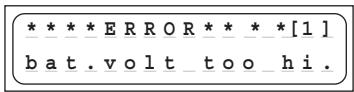
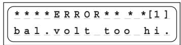
If the charger detects an excessive voltage, e.g. incorrect setting of the cell count with a Lithium or lead-acid battery, this error message is displayed.
The same error message may also appear if the cells connected to the charger are overcharged.
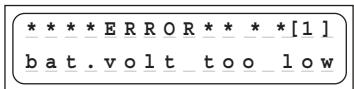
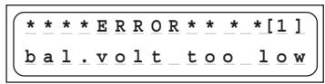
If the charger detects too low a voltage, e.g. incorrect setting of the cell count with a Lithium or lead-acid battery, this error message is displayed.
The purpose of this error message is to avoid the cells becoming deep-discharged due to an incorrect setting.
If the charger detects an excessive cell voltage at the balancer input, this error message appears. The error message appears at the following voltages: LiPo >4.3V Lilo >4.2V LiFe >3.9V NiCd / NiMH >2.0V This error message may also appear if the cells connected to the charger are overcharged.
If the charger detects an excessively low cell voltage at the balancer input, this error message appears. The error message appears at the following voltages: LiPo < 2.75V , Lilo < 2.75V , LiFe < 2.0V , NiCd / NiMH < 0.1V
If this should occur, we recommend that you give the battery an initial charge for example in the LiFe Program Mode for a few minutes (max. five minutes), which allows cell voltages down to 2.0V without connecting the balancer plug.
Warning: it may be that the battery contains damaged cells, and the battery pack must therefore be monitored very closely while it is being recharged. As soon as the voltage is high enough, for safety reasons the battery must always be charged with the balancer plug connected (explosion and fire hazard!).
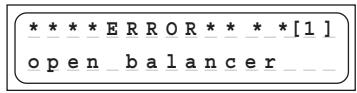
When starting in NiCD/NiMH balance mode, if the balancing connector is not connected to the balancing port of the charger, this error should occur.
While the balancing connector is connected to the balancing port of the charger, if the balancing connector is disconnected from the balancing port of the charger during charge or discharge, this error should occur.
18. PC-Interface
You can download the appropriate USB serial driver CP210x_Drivers.exe for this battery charger at www.graupner.de product search 6466.
Install this driver first. You will also need the USB-adapter #7168.6 and the adapter wire #6466.S.
Connect the USB lead to the charger and to a free USB port on your PC.
PC software can be downloaded at www.graupner.de or www.logview.info.
This software enables you to display battery curves and much more.
With the firmware upgrader software, firmware upgrades can be done by the user.
18. Cleaning and maintenance
The charger is entirely maintenance-free in use, and requires no servicing of any kind. However, it is in your own interests to protect the unit from dust, dirt and damp.
To clean the charger, disconnect it from the car battery and any other battery, and wipe it clean with a dry cloth (don't use cleaning agents!).
19. Notes on handling rechargeable batteries
- Charging single Ni-Cd or Ni-MH cells, and packs consisting of 1 ... 4 cells, presents the automatic charge termination circuit with a difficult task. The voltage peak is quite small in such cases, and it cannot be guaranteed that the cut-off circuit will work reliably. In such conditions the automatic circuit may not be triggered, or may not terminate the charge at the correct time. For this reason it is important to carry out a series of monitored test charge processes with your packs in order to establish whether the charge process is terminated reliably.
- Warm batteries offer much higher performance than cold ones, so don't be surprised if your batteries don't seem so effective in the winter.
- Overcharging and deep-discharging batteries lead to irreparable damage to the cells, and permanently reduces their maximum performance and effective capacity.
- Never store batteries for a long time in an uncharged, discharged or partially charged state. Charge your batteries before storing them, and check their state of charge from time to time.
- When purchasing batteries we recommend that you buy good quality products exclusively. Start by charging new packs at low rates, and work up gradually towards higher currents.
- Batteries should not be charged until shortly before use, as they are then able to deliver their best performance.
- Do not solder directly to battery cells. The temperatures which occur during soldering can easily damage the seals and safety valves of the cells. If this should happen, the battery may lose electrolyte or dry out, and some of its potential performance will be lost.
- Charging any battery at high currents shortens the life expectancy of the pack. Don't exceed the maximum values stated by the manufacturer.
Overcharging inevitably reduces the capacity of the battery, so do not recharge a hot pack, or one which has already been charged. - Charging and discharging any battery at a high current shortens the life expectancy of the pack. Don't exceed the maximum values stated by the manufacturer.
- Lead-acid batteries are not capable of being charged at high currents. Never exceed the maximum charge rate stated by the battery manufacturer.
- Protect batteries from vibration, and do not subject them to mechanical stress or shock.
- Batteries can generate explosive gas (hydrogen) when on charge and when being discharged, so it is important to provide good ventilation.
- Do not allow batteries to come into contact with water - explosion hazard.
- Never short-circuit battery contacts - explosion hazard.
- Batteries can explode or burn, if they overheat. We suggest to use a LiPo-security hard case Order-No. 8370 or 8371 with all Li-battery types and with NiCd und NiMH-batteries for charging.
- Do not open battery cells - corrosion hazard.
- It is best to "balance", or even up the cells in Ni-Cd and Ni-MH battery packs by first discharging all the cells separately to 0.9...1.1V and then charging up the pack.
- Please don't be surprised if your batteries are not as willing to accept charge in winter as in summer. The ability of a cold cell to accept and store charge is much lower than that of a warm one.
- Battery disposal: exhausted batteries are not ordinary household waste, and you must not dispose of them in the domestic rubbish. The retail outlet where you purchase your batteries should have a battery recycling container for proper disposal. Trade outlets are obliged by law to accept exhausted batteries for disposal.
20. Specification
Battery Output 1:
Charge currents / power 100 mA to 5.0 A / max. 50 W with internal power supply 100 mA to 5.0 A/max. 50W with external 12...15V DC power supply Discharge currents / power 100 mA to 1 A / max. 5 W
Ni-Cd & Ni-MH batteries:
Cell count 1-14 cells Capacity min.0,1 Ah to 8,0 Ah
Lithium batteries:
Cell count 1-6 cells
Cell voltage 3,3 V (LiFe), 3,6 V (Lilo) / 3,7 V (LiPo/LiMn)
Capacity min. 0,05 Ah to 8,0 Ah
Lead-acid / lead-gel batteries:
Cell count 1,2,3,6 cells Battery voltage 2,4,6,12V Capacity min.1Ah
Battery Output 2 and 3:
Charge currents / power 0.1 A to 1.0 A
Ni-Cd & Ni-MH batteries:
Cell count 1-8 cells Capacity min.0,1 Ah to 6,0 Ah
Lithium batteries:
Cell count 2 - 3 cells
Cell voltage 3,3 V (LiFe), 3,6 V (Lilo) / 3,7 V (LiPo/LiMn)
Capacity min. 0,05 Ah to 5,5 Ah
General:
Operating voltage range DC input 11,0 to 15 V
Operating voltage range AC input 100 ~ 240V
Output power overall max.: 50W
Car battery required 12 V, min. 30 Ah
Mains PSU required 12-15V, min. 8,5 A stabilised1)
No-load current drain approx 0.1 A
balancer connector Output 1: 1...6 NiMH/NiCd/LiPo/Lilo/LiFe cells
balancer connector Output 2, 3: 2...3 LiPo/Lilo/LiFe cells
balancing current Output 1: NiMH/NiCd: 0.1A, LiPo/Lilo/LiFe: 0.3A
balancer current Output 2, 3: LiPo/Lilo/LiFe: max. 42mA
Low-voltage cut-off approx 11,0 V
Weight approx. 730 g
Dimensions approx. (WxDxH) 185 x 169 x 55 mm
All data assumes a car battery voltage of 12.7V
The stated values are guidelines, and may vary according to battery state, temperature etc.
1)When powered by a main PSU, the charger will only operate correctly if the PSU is suitable in terms of voltage, stability, maximum load capacity etc. You can avoid problems by using only the PSUs which we specifically recommend.
22. Environmental Protection Notes, Manufacturer's declaration
Environmental Protection Notes

When this product comes to the end of its useful life, you must not dispose of it in the ordinary domestic waste. The correct method of disposal is to take it to your local collection point for recycling electrical and electronic equipment. The symbol shown here, which may be found on the product itself, in the operating instructions or on the packaging, indicates that this is the case.
Individual markings indicate which materials can be recycled and re-used. You can make an important contribution to the protection of our common environment by re-using the product, recycling the basic materials or recycling redundant equipment in other ways.
Remove batteries from your device and dispose of them at your local collection point for batteries.
In case of R/C models, you have to remove electronic parts like servos, receiver, or speed controller from the product in question, and these parts must be disposed of with a corresponding collection point for electrical scrap.
If you don't know the location of your nearest disposal centre, please enquire at your local council office.
Manufacturer's declaration from Graupner GmbH & Co. KG, Henrietttenstr. 94 - 96, D-73230 Kirchheim /Teck, Germany
Content of the manufacturer's declaration
If material defects or manufacturing faults should arise in a product distributed by us in the Federal Republic of Germany and purchased by a consumer (§ 13 BGB), we, Graupner GmbH & Co. KG, D-73230 Kirchheim/Teck, Germany, acknowledge the obligation to correct those defects within the limitations described below.
The consumer is not entitled to exploit this manufacturer's declaration if the failure in the usability of the product is due to natural wear, use under competition conditions, incompetent or improper use (including incorrect installation) or external influences.
This manufacturer's declaration does not affect the consumer's legal or contractual rights regarding defects arising from the purchase contract between the consumer and the vendor (dealer).
Extent of the guarantee
If a claim is made under guarantee, we undertake at our discretion to repair or replace the defective goods. We will not consider supplementary claims, especially for reimbursement of costs relating to the defect (e.g. installation / removal costs) and compensation for consequent damages unless they are allowed by statute.
This does not affect claims based on legal regulations, especially according to product liability law.
Guarantee requirements
The purchaser is required to make the guarantee claim in writing, and must enclose original proof of purchase (e.g. invoice, receipt, delivery note) and this guarantee card. In the case of speed controllers the purchaser must also send us the motor used, and state the number of battery cells, so that we can investigate the cause of the defect. The purchaser must send the defective goods to us at his own cost, using the following address:
Graupner GmbH & Co. KG, Service Department, Henriettenstr. 94 - 96, D-73230 Kirchheim / Teck, Germany
or UK: GLIDERS, Brunel Drive, Newark, Nottinghamshire, NG24 2EG, (+44) 16 36 63 05 39
The purchaser should state the material defect or manufacturing fault, or the symptoms of the fault, in as accurate a manner as possible, so that we can check if our guarantee obligation is applicable.
The goods are transported from the consumer to us and from us to the consumer at the risk of the consumer.
Duration of validity
This declaration only applies to claims made to us during the claim period as stated in this declaration. The claim period is 24 months from the date of purchase of the product by the consumer from a dealer in the Federal Republic of Germany (purchase date). If a defect arises after the end of the claim period, or if the evidence or documents required according to this declaration in order to make the claim valid are not presented until after this period, then the consumer forfeits any rights or claims from this declaration.
Limitation by lapse of time
If we do not acknowledge the validity of a claim based on this declaration within the claim period, all claims based on this declaration are barred by the statute of limitations after six months from the time of implementation; however, this cannot occur before the end of the claim period.
Applicable law
This declaration, and the claims, rights and obligations arising from it, are based exclusively on the pertinent German Law, excluding the norms of international private law, and excluding UN retail law.
Coupure Delta Peak (-Δ Peak)
Coupure Delta-Peak (-Δ Peak)
Raccordement Balancer 1
EU Conformity Declaration
We hereby declare that the following product:
ULTRA TRIO PLUS 14; Order-No.6466
conforms with the essential protective requirements as laid down in the directive for harmonising the statutory directives of the member states concerning electro-magnetic interference (89/336/EWG) and LVD (73/23/EG).
This product has been tested for electro-magnetic interference in accordance with the following norms:
EMV: EN 61000-3-2 / EN 61000-3-3
EN 55014-1 / EN 55014-2
LVD: EN 60950-1
This declaration was produced by:
and is valid for the manufacturer / importer of the product
73230 Kirchheim/Teck, Germany, on 03.12.09

Hans Graupner
Managing Director
Graupner GmbH & Co. KG, Henriettensstraße 94-96, 73230 Kirchheim/Teck, Germany guarantees this product for a period of 24 months from date of purchase.
The guarantee applies only to such material or operational defects witch are present at the time of purchase of the product.
Damage due to wear, overloading, incompetent handling or the use of incorrect accessories is not covered by the guarantee.
The user's legal rights and claims under guarantee are not affected by this guarantee.
Please check the product carefully for defects before you are make a claim or send the item to us, since we are obliged to make a charge for our cost if the product is found to be free of faults.