
MX-12 - Radio transmitters for modeling GRAUPNER - Free user manual and instructions
Find the device manual for free MX-12 GRAUPNER in PDF.


| Brand | GRAUPNER |
| Model | MX-12 |
| Product type | 6-channel radio transmitter for modeling (plane, helicopter, car, boat) |
| Dimensions (L x W x H) | 190 x 195 x 85 mm |
| Weight | 870 g (with batteries) |
| Supply voltage | 9.6 - 12 V |
| Power consumption | 175 mA |
| Transmitter battery type | NiMH 8 cells (1700 mAh) recommended |
| Antenna | Telescopic, length approximately 1150 mm |
| Available frequencies | 35 MHz, 40 MHz, 41 MHz (depending on version) |
| Modulation | FM (PPM) and SPCM (PCM) |
| Memory | 10 models |
| Display | LCD with adjustable contrast |
| Number of channels | 6 (4 proportional with trim, 2 on switch) |
| Main functions | Dual Rate, Expo, Sub Trim, Travel Adjust, programmable mixes, Fail Safe, Flaperon, Elevon, V-tail, CCPM, throttle/pitch curves, Throttle Hold/Cut, trainer/student mode |
| Connectivity | DSC port for simulator, charging port |
| Care and cleaning | Clean only with a dry, soft cloth |
| Safety | Always turn on the transmitter before the receiver; turn off the receiver before the transmitter; respect frequencies; test range before each flight |
| Spare parts and repairability | Telescopic antenna (ref. 3100.6), training cable (4179.1), batteries, crystals; repair by Graupner service |
| Warranty | 24 months from date of purchase |
Frequently Asked Questions - MX-12 GRAUPNER
User questions about MX-12 GRAUPNER
0 question about this device. Answer the ones you know or ask your own.
Ask a new question about this device
Download the instructions for your Radio transmitters for modeling in PDF format for free! Find your manual MX-12 - GRAUPNER and take your electronic device back in hand. On this page are published all the documents necessary for the use of your device. MX-12 by GRAUPNER.
USER MANUAL MX-12 GRAUPNER
Computer System mx-12
6-Kanal Digital-Proportional-Fernlenkset
Direct Servo Control (DSC)
Gaskurven (Throttle Curve)
Pitchkurven (Pitch Curve)
| MODUS 1 (Gas rechts) | MODUS 2 (Gas links) | ||
| TS-Nick | Motor/Pitch | Motor/Pitch | TS-Nick |
| Heck | Motor/Pitch | Heck | TS-Roll |
| TS-Nick | Motor/Pitch | Motor/Pitch | TS-Roll |
| MODUS 3 (Gas rechts) | MODUS 4 (Gas links) | ||
| TS-Nick | Motor/Pitch | Motor/Pitch | TS-Nick |
| Heck | Motor/Pitch | Heck | Heck |
| TS-Nick | Motor/Pitch | Motor/Pitch | TS-Nick |
System-Modus
Statement This segment follows the requirements that apply for the above mentioned qualifications.
CETECOM ICT Services is authorized to act as Notified Body in accordance with the R&TE Directive 1999/5EC
CTECOM ICT Services GmbH, Unterlehrheimer Straße 6-10, D-66117 Saarbrücken, Germany
CETEC
Annex 1 of the Certificate, 'EXPERT OPINION' Registration no.: E814320S-EO Date: 28.04.2005
Product Characteristics:
Transmitter for remote controlled model
Frequency Range
PEO Export Source (
1. Supervision (SIS)
Type of Modulation
Number of RF-Channels
1
Channel Separation
Operation Mode
Duty Cycle
Antenna
Temperature Range
Conformity Details:
1.01 According to the application 1
- Konformitätserklarung
Konformitätserklung gemäß dem Gesetz über Funkanlagen und
Translational and commercial communications
Translational sendinrichtungen (FTEG) und der Richteinline 1999/5/EG (R&TTEG) of Conformity in accordance with the Radio and Telecommunications Terminal Equipment Standard
Act (FTEG) and Directive 1999/5/EG (H&TTE)
mbH & Co.KG
Co.10000
Chheim/Teck
ss das Produkt: mx-12
The product
engszech: Funkanlage zur Fernsteuerung von I
pose Radioedase: 2
Newark, Nottinghamshire
NG24 2EG
( +44) 16 36 61 05 39
RC Service Z. Hnizdil
Letecka 666/22
CZ-16100 Praha 6 - Ruzyne
(+42)233313095
Belgie/Nederland
Jan van Mouwerik
Slot de Houvelaan 30
NL 3155 Maasland VT
(+)105913594
Graupner GmbH & Co. KG, Henriettenstraße 94-96. 73230 Kirchheim/Teck, Germany guarantees this product for a period of 24 months from date of purchase. The guarantee applies only to such material or operational defects witch are present at the time of purchase of the product. Damage due to wear, overloading, incompetent handling or the use of incorrect accessories is not covered by the guarantee. The user's legal rights and claims under guarantee are not affected by this guarantee. Please check the product carefully for defects before you are make a claim or send the item to us, since we are obliged to make a charge for our cost if the product is found to be free of faults.
Date of purchase/delivery:
Date de remise:
Name des Kaufers:
Owner's name:
Nom de I'achateur:
StraBe, Wohnort:
Complete adress:
Domicie et rue:
Stamp and signature of dealer:
R E M O T E C O N T R O L
GRAUPNER GMBH & CO. KG POSTFACH 1242 D-73220 KIRCHHEIM/TECK GERMANY http://www.graupner.de
Printed in Germany PN.JI-01
Description of radio control system. 7
Charging the transmitter battery. 8
Transmitter description. 9
Direct servo control. 11
Connections and installations
-
For Airplane. 12
-
For Helicopter. 13
Key input and display. 14
Alarm and error display. 14
Input mode and function. 15
Program
Function mode. 16
System mode. 17
List mode. 18
Function mode AIRPLANE
Dual Rates and Exponential. 19
Servo Reversing. 19
Sub Trim. 20
Travel Adjust. 20
Elevator to flap mixing. 21
Aileron to rudder mixing. 21
Throttle Cut switch. 22
Flap System 22
Differential aileron mixing 23
Programmable Mixing (1~4) 23
Fail Safe. 24
Servo Travel Screen 25
Function mode HELICOPTER
Dual Rates and Exponential. 26
Servo Reversing 26
Sub Trim. 27
Travel Adjust. 27
CCPM Swashplate Mixing. 28
Throttle Cut Switch 29
Throttle Hold. 29
Throttle Curves. 30
Pitch Curves. 31
Revolution Mixing (Non-heading lock Gyro only) 33
Programmable Mixing (1~2) 33
Fail Safe. 34
Servo Travel Screen 35
System Mode
Model Selection. 36
Model Name Entry 36
Model Type Selection 37
Model Copy Function 37
Modulation Selection 38
Stick Mode. 38
Trainer Function 39
Switch Select. 40
Wing Type Selection. 41
Swashplate Selection 44
Appendix
Approved operating frequencies. 45
Approval Certificate / Conformity. 46
Guarantee certificate. 47
The sole purpose of this manual is to provide information. It is subject to modification at any time, and must not be considered as any form of obligation on the part of the GRAUPNER company. GRAUPNER accepts no responsibility or liability for errors or inaccuracies which may be found in the information section of this manual.
Environmental Protection Notes
When this product comes to the end of its useful life, you must not dispose of it in the ordinary domestic waste. The correct method of disposal is to take it to your local collection point for recycling electrical and electronic equipment. The symbol shown here, which may be found on the product itself, in the operating instructions or on the packaging, indicates that this is the case.
Individual markings indicate which materials can be recycled and re-used. You can make an important contribution to the protection of our common environment by re-using the product, recycling the basic materials or recycling redundant equipment in other ways.
Remove batteries from your device and dispose of them at your local collection point for batteries.

If you don't know the location of your nearest disposal centre, please enquire at your local council office.
Safety notes
Please read carefully!
We all want you to have many hours of pleasure in our mutual hobby of modelling, and safety is an important aspect of this. It is absolutely essential that you read right through these instructions and take careful note of all our safety recommendations. If you are a beginner to the world of radio-controlled model aircraft, boats and cars, we strongly advise that you seek out an experienced modeller in your field and ask him for help and advice. These instructions must be handed on to the new owner if you ever sell the transmitter.
Application
This radio control system may only be used for the purpose for which the manufacturer designed it, i.e. for operating radio-controlled models which do not carry humans. No other type of use is approved or permissible.
Safety notes
SAFETY IS NO ACCIDENT
and ...
RADIO-CONTROLLED MODELS ARE NOT PLAYTHINGS
Even small models can cause serious personal injury and damage to property if they are handled incompetently.
Technical problems in electrical and mechanical systems can cause motors to rev up or burst into life unexpectedly, with the result that parts may fly off at great speed, causing considerable injury.
Short-circuits of all kinds must be avoided at all times. Short-circuits can easily destroy parts of the radio control system, but even more dangerous is the acute risk of fire and explosion, depending on the circumstances and the energy content of the batteries.
The circumstances and the energy content of the batteries.
Aircraft and boat propellers, helicopter rotors, open gearboxes and all other rotating parts which are driven by a motor or engine represent a constant injury hazard. Do not touch these items with any object or part of your body. Remember that a propeller spinning at high speed can easily slice off a finger! Ensure that no other object can make contact with the driven components.
Protect all electronic equipment from dust, dirt, damp, and foreign bodies. Avoid subjecting the equipment to vibration and excessive heat or cold. Radio control equipment should only be used in „normal“ ambient temperatures, i.e. within the range -15°C to +55°C. Avoid subjecting the equipment to shock and pressure.
Check the units at regular intervals for damage to cases and leads. Do not re-use any item which is damaged or has become wet, even after you have dried it out thoroughly. Use only those components and accessories which we expressly recommend. Be sure to use only genuine matching GRAUPNER connectors of the same design with contacts of the same material. Use only genuine GRAUPNER plug-in crystals on the appropriate frequency band. When deploying cables note that they must not be under tension, and should never be bent tightly or kinked, otherwise they may fracture. Avoid sharp edges which could wear through the cable insulation.
Check that all connectors are pushed home firmly before using the system. When disconnecting components, pull on the connectors themselves - not on the wires.
It is not permissible to carry out any modifications to the RC system components. Avoid reverse polarity and short-circuits of all kinds, as the equipment is not protected against such errors.
Installing the receiving system and deploying the receiver aerial
In a model aircraft the receiver must be packed in soft foam and stowed behind a stout bulkhead, and in a model boat or car should be protected effectively from dust and spray.
The receiver must not make contact with the fuselage, hull or chassis at any point, otherwise motor vibration and landing shocks will be transmitted directly to it. When installing the receiving system in a model with a glowplug or petrol engine, be sure to install all the components in well protected positions so that no exhaust gas or oil residues can reach the units and get inside them. This applies above all to the ON / OFF switch, which is usually installed in the outer skin of the model. Secure the receiver in such a way that the aerial, servo leads and switch harness are not under any strain.
The receiver aerial is permanently attached to the receiver. It is about 100 cm long and must not be shortened or extended. The aerial should be routed as far away as possible from electric motors, servos, metal push-rods and high-current cables. However, it is best not to deploy the aerial in an exactly straight line, but to angle it: e.g. run it straight to the tailplane, then leave the final 10 - 15 cm trailing down, as this avoids reception „blind spots“ when the model is in the air. If this is not possible we recommend that you lay out part of the aerial wire in an S-shape inside the model, close to the receiver if possible.
Safety notes
Installing the servos
Always install servos using the vibration-damping grommets supplied. The rubber grommets provide some degree of protection from mechanical shocks and severe vibration.
Installing control linkages
The basic rule is that all linkages should be installed in such a way that the pushrods move accurately, smoothly and freely. It is particularly important that all servo output arms can move to their full extent without fouling or rubbing on anything, or being obstructed mechanically at any point in their travel. It is important that you should be able to stop your motor at any time. With a glow motor this is achieved by adjusting the throttle so that the barrel closes completely when you move the throttle stick and trim to their end-points. Ensure that no metal parts are able to rub against each other, e.g. when controls are operated, when parts rotate, or when motor vibration affects the model. Metal-to-metal contact causes electrical "noise" which can interfere with the correct working of the receiver.
Always extend the transmitter aerial fully before operating your model.
Transmitter field strength is at a minimum in an imaginary line extending straight out from the transmitter aerial. It is therefore fundamentally misguided to "point" the transmitter aerial at the model with the idea of obtaining good reception.
When several radio control systems are in use on adjacent channels, the pilots should always stand together in a loose group. Pilots who insist on standing away from the group endanger their own models as well as those of the other pilots.
Pre-flight checking
If there are several modellers at the site, check carefully with all of them that you are the only one on „your“ channel before you switch on your own transmitter. If two modellers switch on transmitters on the same channel, the result is interference to one or both models, and the usual result is at least one wrecked model.
Before you switch on the receiver, ensure that the throttle stick is at the stop / idle end-point.
Always switch on the transmitter first, and only then the receiver.
Always switch off the receiver first, and only then the transmitter.
If you do not keep to this sequence, i.e. if the receiver is at any time switched on when "its" transmitter is switched off, then the receiver is wide open to signals from other transmitters and any interference, and may respond. The model could then carry out uncontrolled movements, which could easily result in personal injury or damage to property. The servos may run to their end-stops and damage the gearbox, linkage, control surface etc. Please take particular care if your model is fitted with a mechanical gyro: Before you switch your receiver off, disconnect the power supply to ensure that the motor cannot run up to high speed accidentally. The gyro can generate such a high voltage as it runs down that the receiver picks up apparently valid throttle commands, and the motor could respond by unexpectedly bursting into life.
Range checking
Before every session check that the system works properly in every respect, and has adequate range. This means checking that all the control surfaces respond
correctly and in the appropriate direction to the transmitter commands at a suitable ground range.
Repeat this check with the motor running, while a friend holds the model securely for you.
Operating your model aircraft, helicopter, boat or car Never fly directly over spectators or other pilots, and take care at all times not to endanger people or animals. Keep well clear of high-tension overhead cables. Never operate your model boat close to locks and full-size vessels. Model cars should never be run on public streets or motorways, footpaths, public squares etc.
Checking the transmitter and receiver batteries
It is essential to stop using the radio control system and recharge the batteries well before they are completely discharged. In the case of the transmitter this means - at the very latest - when the message „Battery must be charged“ appears on the screen, and you hear an audible warning signal. It is vital to check the state of the receiver battery at regular intervals. When the battery is almost flat you may notice the servos running more slowly, but it is by no means safe to keep flying or running your model until this happens. Always replace or recharge the batteries in good time. Keep to the battery manufacturer's instructions and don't leave the batteries on charge for longer than stated. Do not leave batteries on charge unsupervised. Never attempt to recharge dry cells, as they may explode.
Rechargeable batteries should always be recharged before every session. When charging batteries it is important to avoid short-circuits. Do this by first connecting the charge lead banana plugs to the charger, taking care to maintain correct polarity. Only then connect the charge lead to the transmitter or receiver battery.
Safety notes
Disconnect all batteries and remove them from your model if you know you will not be using it in the near future.
Capacity and operating times
This rule applies to all forms of electrical power source: battery capacity is reduced every time you charge it. At low temperatures capacity is greatly reduced, i.e. operating times are shorter in cold conditions.
Frequent charging, and / or the use of maintenance programs, tends to cause a gradual reduction in battery capacity. We recommend that you check the capacity of all your rechargeable batteries at least every six months, and replace them if their performance has fallen off significantly.
Use only genuine GRAUPNER rechargeable batteries!
Suppressing electric motors
All conventional electric motors produce sparks between commutator and brushes to a greater or lesser extent depending on the motor type; the sparking generates serious interference to the radio control system. In electric-powered models every motor must therefore be effectively suppressed.
Suppressor filters effectively eliminate such interference, and should always be fitted. Please read the notes and recommendations supplied by the motor manufacturer. Refer to the main GRAUPNER FS catalogue for more information on suppressor filters.
Servo suppressor filter for extension leads
Order No. 1040
Servo suppressor filters are required if you are obliged to use long servo extension leads, as they eliminate the danger of de-tuning the receiver. The filter is connected directly to the receiver input.
In very difficult cases a second filter can be used, positioned close to the servo.
Using electronic speed controllers
Electronic speed controllers must be chosen to suit the size of electric motor which they will control. There is always a danger of overloading and possibly damaging the speed controller, but you can avoid this by ensuring that the controller's current-handling capacity is at least half the motor's maximum stall current.
Particular care is called for if you are using a "hot" (i.e. upgrade) motor, as any low-turn motor (small number of turns on the winding) can draw many times its nominal current when stalled, and the high current will wreck the speed controller.
Electrical ignition systems
Ignition systems for internal combustion engines can also produce interference which has an adverse effect on the working of the radio control system.
Electrical ignition systems should always be powered by a separate battery - not the receiver battery.
Be sure to use effectively suppressed spark plugs and plug caps, and shielded ignition leads.
Keep the receiving system an adequate distance away from the ignition system.
Caution:
Radio control systems may only be operated on the frequency bands and spot frequencies approved in each EU country. You will find information on frequencies in the section entitled „Approved operating frequencies". It is prohibited to operate radio control systems on any other frequency, and such misuse will be punished by the relevant authorities.
Static charges
Lightning causes magnetic shock waves which can interfere with the operation of a radio control transmitter even if the thunderstorm actually occurs several kilometres away. For this reason cease flying operations immediately when you notice an electrical storm approaching.
Static charges through the transmitter aerial can be life-threatening!
Care and maintenance
Don't use cleaning agents, petrol, water or other solvents to clean this equipment. If the case, the aerial etc. gets dirty, simply wipe the surfaces clean with a soft dry cloth.
Liability exclusion / Compensation
As manufacturers, we at GRAUPNER are not in a position to influence the way you install, operate and maintain the radio control system components. For this reason we are obliged to refute all liability for loss, damage or costs which are incurred due to the incompetent or incorrect use and operation of our products, or which are connected with such operation in any way.
Unless otherwise prescribed by law, the obligation of the GRAUPNER company to pay compensation is limited to the invoice value of that quantity of GRAUPNER products which was immediately and directly involved in the event in which the damage occurred. This does not apply if GRAUPNER is found to be subject to unlimited liability according to binding legal regulation on account of deliberate or gross negligence.
Computer system mx-12
6 channel digital proportional radio control system
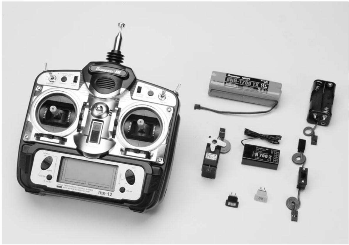
Computer radio control system with 10 model memories, incorporating high-level technology. Modern computer system for excellent reliability and security. Simplified rotary programming technology for straightforward programming.
High-contrast graphic screen provides an accurate display of the transmitter battery voltage, modulation, model type, model name, model memory number, set-up data, throttle and collective pitch curves and model operating time.
- All-purpose radio control system, fully expanded as standard
- High-quality radio control system for F3A, F3B, F3C, F3D, F3E model aircraft, deltas and V-tail models. Fully expanded, offering 6 channels: 4 proportional channels with trims, 2 switched channels
- Convenient mode selector for simple switching between stick MODES 1 - 4 (throttle right / left). All mixer, set-up and reverse memory data are automatically converted if you switch modes
- Convenient wing mixer programs: DIFFERENTIAL FLAPERON (aileron differential mixer), ELEVON (deltas: aileron-elevator mixer), V-TAIL (V-tail models: elevator - rudder mixer)
- Convenient swashplate programs: SWASHPLATE TYPE (swashplate: 1 servo, 2 servos 180° , 3 servos 120° , 3 servos 90° )
10 model memories, with transfer of all essential programming and set-up parameters - Compatibility with FM and FMsss (PPM) receivers as well as SPCM receiving systems
- High-contrast Multi-Data-Display LCD screen provides accurate monitoring even in bright sunlight; screen displays information such as mixer input data, set-up values, directions of rotation, trim values, programming information in multi-function programs, and transmitter battery operating voltage
- Wide range of mixer system, plus precisely variable end point and centre positions, making the system suitable for the demanding operator of model aircraft, boats and cars.
- REVERSE function, programmable for six servos
- MONIT: servo travel monitor for six servos
-
MODEL NAME and model number programmable separately
-
MODULATION: switchable PPM / SPCM
- DUAL RATE / EXPO switchable to two positions and programmable for three servo functions, available range 5 to 125% .
DIFFERENTIAL FLAPERON (differential aileron mixer) - SUB-trim memory system for offsetting all servo centres; also for adjusting older servo types and servos with no standard centre
- TRAVEL ADJUST: separate travel adjustment for both end-points of all servos adjustment range 0 to 150% . New type of adjustment enables programming of symmetrical and asymmetrical servo travels, e.g. to compensate for one warped wing or special applications.
- DSC socket for connection to flight simulator
- Integral visual and audible alarm system for transmitter battery and Lithium back-up battery
Set contents
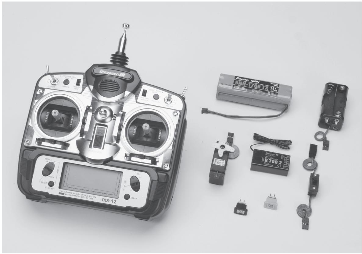
mx-12 micro-computer transmitter with integral NiMH 8 NH-1700 TX battery, R 700 receiver on the appropriate frequency, pair of crystals on the same frequency, C 577 servo, switch harness, battery holder for receiving system
Six-channel micro-computer radio control system, fully expanded. Switchable PPM / SPCM modulation (4 proportional functions with trims, 2 switched functions)
Order No. 4722 35 MHz band
Order No. 4722.B 35 MHz-B-Band
Order No. 4723 40 MHz band
Order No. 4723.41* 41 MHz band
*For export only
Specification mx-12 transmitter
| Transmission system | FM / FMsss (PPM) and SPCM |
| FMsss crystals | 35 MHz band; Order No. 3864.61 - .80 40 MHz band; Order No. 4064.50 - .92 41 MHz band; Order No. 4164.400 - .420 |
| Channel spacing | 10 kHz |
| Control functions max. | 6 |
| Channel pulse width | 1,5ms +/- 0,5 mx, incl. trim |
| Aerial | 9,6 ... 12 V |
| Current drain approx. | 175 mA |
| Dimensions approx. | 190 x 195 x 85 mm |
| Weight approx. | 870 g incl. transmitter battery |
Specification R 700 micro receiver
| Aerial | 4,8 ... 6 V |
| Current drain approx. | 13 mA |
| Channel spacing | 10 kHz |
| Sensitivity approx. | 10 μV |
| Servo functions | 7 |
| Temperature range | -15° ... + 55°C |
| Aerial length approx. | 950mm |
| Dimensions approx. | 47 x 25 x16 mm |
| Weight approx. | 16 g |
Accessoires
Order No. Description
1121 Neckstrand, 20mm wide
70 Neckstrand, 30mm wide
4179.1 Trainer lead for mx-12
For use with Graupner hand-held
transmitters with DSC sockets
3290.8 Trainer lead for mx-12
For use with Graupner mc-... trans
mitters with trainer sockets
Spare Parts
Order No. Description
3100.6 Antenna for mx-12
Charging the transmitter battery
Charging the transmitter battery
The rechargeable transmitter battery can be charged via the charge socket fitted to the side of the case. The transmitter must be switched „OFF“ for the whole period of the charge process. Never switch on the transmitter when it is still connected to the charger; even a very brief interruption in the charge process can cause the charge voltage to rise to the point where the transmitter is immediately damaged by the excess voltage. Alternatively the interruption may trigger a new charge cycle, which means that the battery will possibly be severely overcharged.
For this reason check carefully that all connectors are secure, and making really good contact. Interruptions due to an intermittent contact, no matter how brief, inevitably cause the charger to malfunction.
Polarity of the mx-12 charge socket
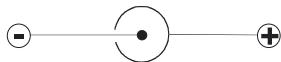
Commercially available battery charge leads produced by other manufacturers are often made up with the opposite polarity. For this reason use genuine GRAUPNER charge leads exclusively.
Charge current
To avoid damage to the transmitter the maximum charge current should not exceed 500mA (0.5 A) with the charge circuit fuse out of circuit (not fitted); with the charge circuit fuse in place: max. 1.5 A.
Notes on recharging transmitter batteries using an automatic charger
- Observe the recommendations provided by the charger manufacturer and the battery manufacturer at all times.
- Carry out a series of test charges to ensure that the automatic charge termination circuit works correctly with your battery. This applies in particular if you are using an automatic charger designed for NiCd batteries to recharge the standard NiMH battery. You may need to adjust the Delta-Peak trigger voltage, if your charger provides this option.
The charge current must be set using the charger's „manual charge current select“ facility, to ensure that the maximum charge current never exceeds 1.5 A. Never allow the charger to set the charge current automatically. - Do not discharge the battery or carry out a battery maintenance program via the integral charge socket. The charge socket is not suitable for this application.
If you intend to charge the transmitter battery at a current higher than 1.5 A, the battery must be removed beforehand, otherwise the transmitter could be damaged through overheating.
Standard chargers
Order-No. 6422 Minilader 2
Order-No. 6427 Multilader 3
Order-No. 6426 Multilader 6E*
Order-No. 6428 Turbomat 6 Plus*
Order-No. 6429 Turbomat 7 Plus*
Automatic chargers with special NiMH charge programs
Order-No. 6419 Ultramat 5* , **
Order-No. 6410 Ultramat 10*
Order-No. 6412 Ultramat 12* , **
Order-No. 6417 Ultramat 25 , **
Order-No. 6416 Ultra Duo Plus 30* , **
To recharge the mx-12 system you will also need the transmitter charge lead, Order No. 3022, and the receiver battery charge lead, Order No. 3021.
12 V power source required.
Transmitter description
Transmitter callouts
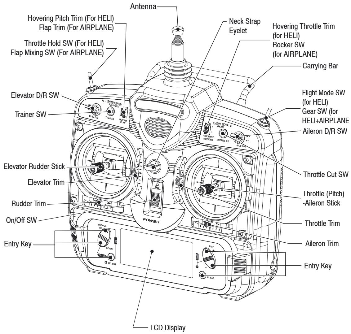
Control stick length adjustment
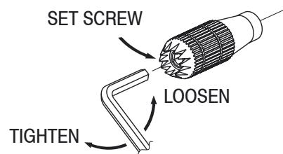
To adjust the stick lenght, use the 2mm Allen wrench (supplied with your mx-12 transmitter) to unlock the set screw. Turn the wrench counterclockwise to loosen the screw. Then turn the stick clockwise to shorten or counterclockwise to lengthen. After the control stick lenght has been adjusted to suit your flying style, tighten the 2mm set screw. If you desire longer sticks, GRAUPNER offers a stick that is approximately one inch longer than standard. This stick, crafted from bar stock aluminum, is available at your local GRAUPNER dealer.
Neck strap attachment
An eyelet is provided on the face of the mx-12 transmitter that allows you to connect a Neck Strap. This hook has been positioned so that your transmitter has the best possible balance when you use the neck strap.
Transmitter description
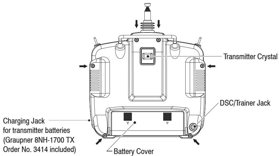
Transmitter Rear
Control Stick tension adjustment
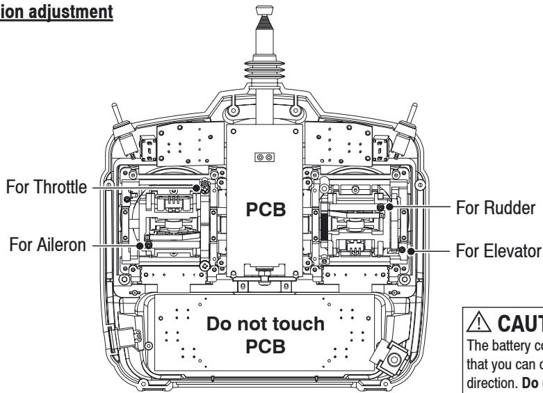
Control Stick tension adjustment
Remove the battery and six transmitter back screws as shown on the previous page. Remove the transmitter back, being careful not to cause damage to any components. Adjust each screw for desired tension (counterclockwise to loosen stick feel; clockwise to tighten stick feel.) When adjusting the throttle ratched tension, make sure that the adjusting screw does not touch the PC board after adjustment is complete.
Throttle Stick
The initial setting for the throttle stick is ratched type. If you don't like this feeling, please follow the following instruction to change it. You will be required a posidrive screwdriver and a pair of tweezers;
- Remove the model from back of the transmitter, by squeezing the lugs and pulling it out.
- Remove the battery cover by pushing it inwards and downwards. Remove the battery.
- Remove 4 screws from the rear 4 corners. Remove 2 screws, 1 from either side of the rear antenna base.
- Carefully separate the 2 halves of the transmitter, starting at the base.
- Unplug the 2 multi pin connectors for ease of access.
- The left side of left stick unit has a black plastic lever and spring, which provide the centring action - move the stick if you are in doubt. Using the tweezers, remove the spring.
- Slide the lever towards the center of the transmitter in order to remove ir from its pivot (move the stick to clear it if necessary).
- Reverse the above process to fit the lever and spring to the right-hand assembly (note; the pivot is at the top of the right-hand stick assembly).
Direct servo control (DSC)
- The left side of the right-hand assembly has a metal strip which provides the ratched friction action. This is held in place by two screws. Undo the screws and transfer the metal strip to the left-hand assembly.
- The mechanical conversion is now completed; check the stick actions are as required and reassemble the transmitter by reversing the above process, not forgetting to plug in the multipin connectors.
Frequency notes
The mx-12 can transmit in either Pulse Code Modulation (PCM) or Pulse Position Modulation (PPM, commonly referred to as FM):
Be certain to observe the following guidelines:
Do not operate your transmitter when another transmitter is using the tame frequency, regardless of whether the second transmitter is PCM, PPM (FM) or AM. You can never operate two transmitters on the same frequency simultaneously without causing interference.
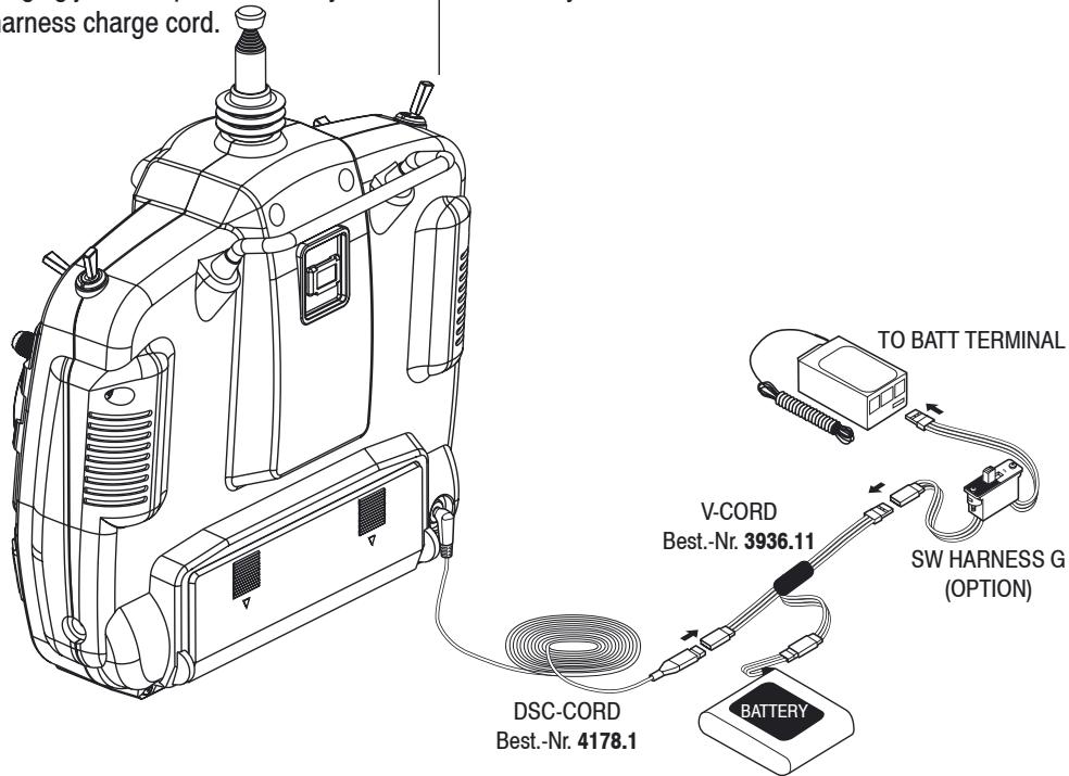
For proper DSC hook-up and operation:
- Leave the transmitter power switch in the OFF position. The transmitter will not transmit any radio frequency (RF) in this position.
- Plug the (supplied) DSC cord into the DSC port in the rear of the transmitter.
- The encoder section of the transmitter will now be operational and the LCD display will be lit.
- Plug the other end of the DSC Cord into the receiver charge receptacle. Turn the switch harness to the ON position.
Note: When you install the charging jack, be sure to hook the charging jack receptable securely into the switch harness charge cord.
Why you should use the DSC function:
- The DSC enables you to check the control surfaces of your aircraft without drawing the fully operational 200mAh from your transmitter battery pack. Instead, you will only draw approximately 70mAh when using the DSC function.
- The DSC function allows you to make final adjustments to your airplane without transmitting any radio signals. Therefore, if another pilot is flying on your frequency, you can still adjust your aircraft and not interfere with the other pilot's aircraft.
Note: This function is for bench-checking your airplane only.
Connections and installations
For Airplane
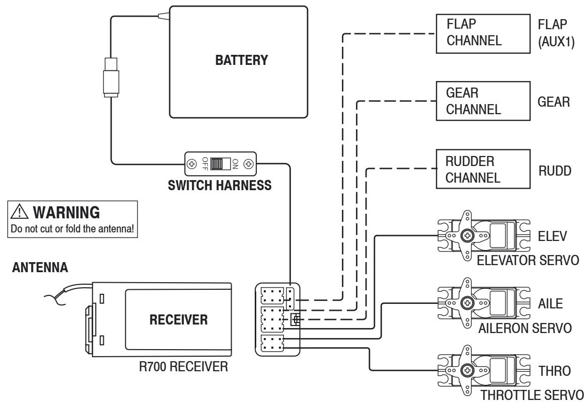
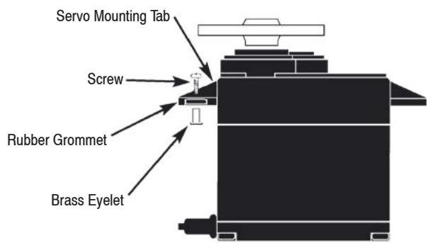
Installation requirements
It is extremely important that your radio system be correctly installed in your model. Here a few suggestions installing your GRAUPNER equipment:
- Wrap the receiver in protective foam rubber that is no less than 3/8 inch thick. Secure the foam to the receiver with #64 rubber bands. This protects the receiver in the event of a crash or a very hard landing.
- The servos should be mounted using rubber grommets and brass eyelets to isolate them from vibration. Do not over-tighten the mounting screws; this will negate the vibration absorption effect of the rubber grommets. The following diagram will assist you in properly mounting your servo. The brass eyelet are pushed from the bottom up in the rubber grommets. When the servo screw is tightened securely, it provides the proper security as well as the proper vibration isolation for your servo.
- The servos must be able to move freely over their entire range of travel. Make sure that the control linkages do not bind or impede the movement of any of the servos.
- Mount all switches away from the engine exhaust and away from any high vibration areas. Make sure the switch operates freely and is able to operate over its full travel.
- Mount the receiver antenna firmly to the airplane to ensure that it will not become entangled on the propeller or control surfaces.
Connections and installations
For Helicopter
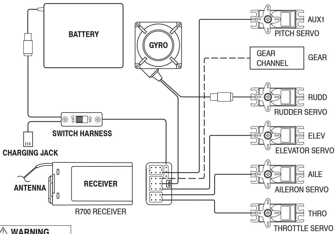

WARNING
Do not cut or fold the antennal!
Key input and display; Alarm and error display
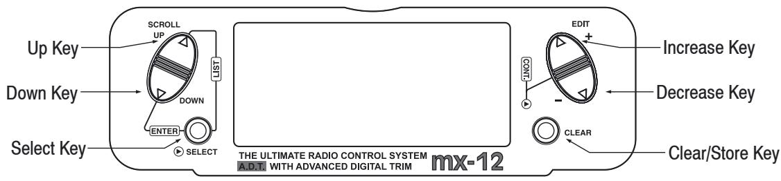
The Function keys are used to move up and down through the functions. The Select key is used to advance the channel or function selected. The increase and
Decrease keys are used to make changes in the selected functions.
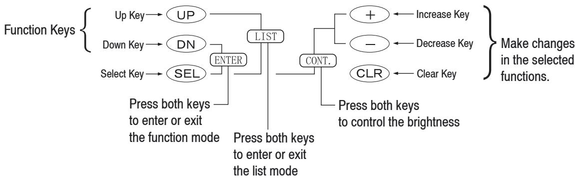
The Key displays in this case
Battery alarm and display
When the transmitter voltage drops below 9.0 volts DC, the display flashes "BATT LOW" and an alarm sounds. If you are flying when this occurs, land immediately.
Backup error display
All preprogrammed data is protected by a five-year lithium battery that guards against main transmitter battery failure. Should de lithium battery fail, the display will indicate BACK ERROR. If this occurs it will be necessary to replace the lithium back-up battery, contact your local dealer. Due to the possibility of extensive damage caused by improper removal or replacement, only your local dealer is authorized to make this change.
Input mode and function
Normal mode
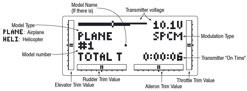
To Function mode (press simultaneously)
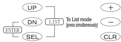
To enter and exit the System mode, press simultaneously then turn on the power switch
Screen contrast adjustment
The screen contrast adjustment feature of the mx-12 allows the user to select the proper tint of the screen for improved clarity and visibility in all weather conditions and temperatures.
To increase the contrast (darken the screen), simply turn the power switch ON and press the SEL and DATA + keys simultaneously. To decrease the contrast (lighten the screen), press the SEL and DATA - keys simultaneously.
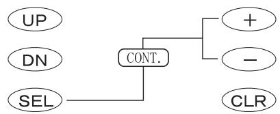
Screen brightness control (press simultaneously)
Advanced Digital Trim (A.D.T.)
The mx-12 digital trims feature the Direct Access display function. While at the Normal display screen, if a trim lever is moved, the screen will automatically change to display the graphic position for the trim being adjusted. The mx-12 Aileron, Elevator, Throttle and Rudder trim levers feature an audible center trim beep. This is helpful in determining the trim levers center position during flight. Please also note that unlike conventional mechanical trim levers, when the mx-12 transmitter is in the off position, no changes can be made to the trim values during transportation.
Model operating time
The standard display shows the total model operating time for the selected memory.
Selecting a new model, or erasing the memory and saving new data in it, resets the model operating time to the value "0:00:00".
To enter the Function mode, switch the transmitter power switch to the On position. Press the Down and Select keys simultaneously, and the display will show the last active program. Pressing either the Up or Down key then scrolls through the functions one by one, according to the Function Mode Flowchart shown below. Once the appropriate function is displayed, changes can be made by pressing the (+) or (-) keys. To select another channel of a particular function, press the Select key. The Function mode is the most often used system to input data.
Function Mode Flowchart
Information pertaining to each function is explained on the page listed next to the function name. Functions will appear in the same order they are shown on this chart.
Accessing the Mode Function
- Move the power switch to the ON position.
- Press the Down and Select keys simultaneously.
- Use either the Up or Down to scroll through the menu and access the applicable function.
AIRPLANE
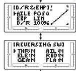
- Dual Rate & EXPonential
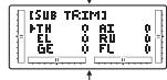
- REVERSING SW
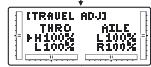
- SUB TRIM
- TRAVEL ADJust
- ELEV → Flap MIXing
- AILE → RUDd MIXing
- THROTTE CUT
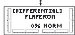
- FLAP SYSTEM
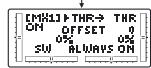
- DIFFERENTIAL (Only in Wing type)
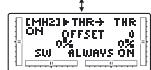
- Program MiXing 1
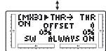
- Program MiXing 2
- Program MiXing 3
- Program MiXing 4
-
FAIL SAFE (Only in SPCM)
-
Servo Travel Screen
HELICOPTER
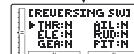
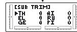
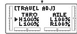
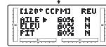
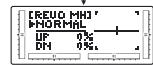
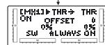
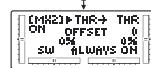
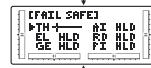
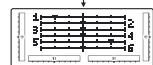
- Dual Rate & EXPonential
- REVERSING SW
- SUB TRIM
- TRAVEL ADJust
- Swash Mixing
(Over 2 servos in Swashplate type - THROttle CUT
- THROTTLE HOLD
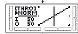
- THRO Curve
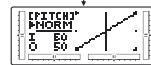
- PITCH Curve
- REVOLusion MiXing
- Program MiXing 1
-
Program MiXing 2
-
FAIL SAFE
(Only in SPCM)
- Servo Travel Screen
System mode
To enter the System mode, press the Down and Select keys simultaneously, then turn the power switch to the ON position. The display will show the last active program. Pressing either the Up or Down key then scrolls through the functions one by one, according to the system mode flowchart is shown to the right. Once the appropriate function is displayed, changes can be made by pressing the (+) or (-) keys.
System Mode Flowchart
Information pertaining to each function is explained on the page listed next to the function name. Functions will appear in the same order they are shown on this chart.
Accessing the System Mode
- Press the Down and Select keys simultaneously.
- Move the power switch to the ON (upper) position.
- Use either the Up or Down key to scroll through the menu and access the applicable function.
AIRPLANE
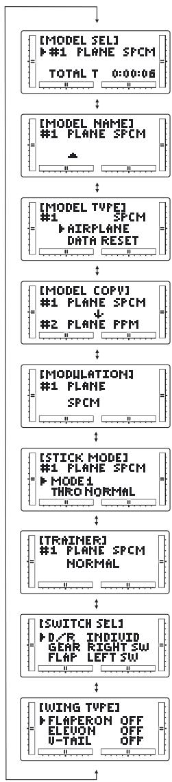
- MODEL SELECT
- MODEL NAME
- MODEL TYPE
& Data reset - MODEL COPY
- MODULATION
- STICK MODE
- TRAINER
- SWITCH SELECT
- WING TYPE
HELICOPTER
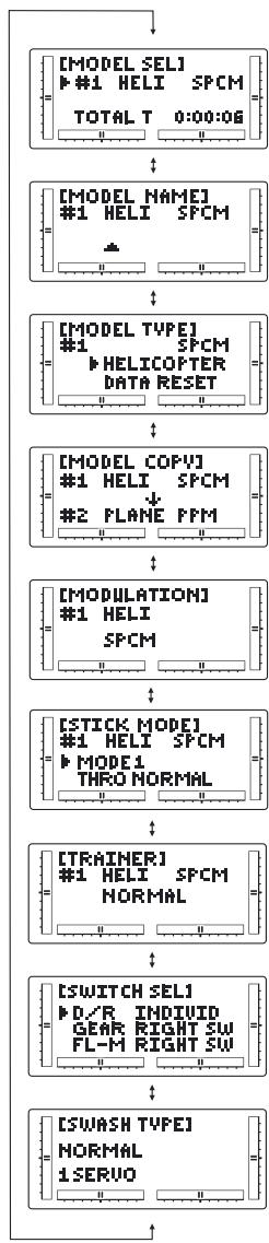
- MODEL SELECT
- MODEL NAME
- MODEL TYPE
& Data reset - MODEL COPY
- MODULATION
- STICK MODE
- TRAINER
- SWITCH SELECT
- SWASH TYPE
List mode
To enter the Function List mode from the Function mode, switch the transmitter power switch to the ON position. Press the Up and Select keys simultaneously. To scroll the functions, first press the Down and Select keys.
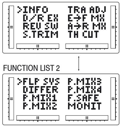
FUNCTION LIST 1
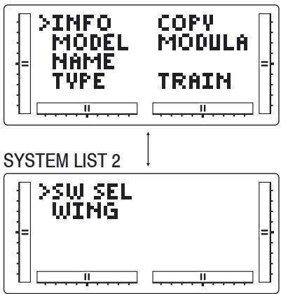
SYSTEM LIST 1
HELICOPTER
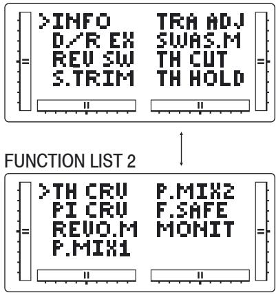
FUNCTION LIST 1
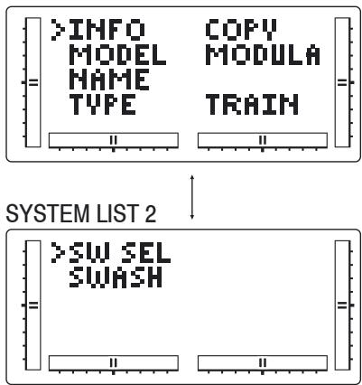
SYSTEM LIST 1
Function mode AIRPLANE
Dual Rates and Exponential; Servo Reversing
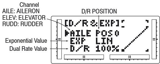
Dual Rates and Exponential
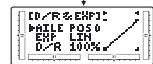
Dual rates are available for the aileron, elevator and rudder channels of yor R/C aircraft. The combined Dual Rate Function is discussed at page XX. Dual rates may be defined as the ability to vary the travel or throw rate of a servo from a switch. Due to the differing travel rates, you will find that the sensitivity of the control either increases or decreases accordingly. A higher rate, or travel, yields a higher overall sensitivity. You may find it easier to think of the Dual-Rate function as double-rates or half-rates.
The amount of travel is adjustable from 0-125% in 1% increments. The factory setting, or default value, for both the 0 and 1 switch positions is 100% .
Exponential reduces the sensitivity in the middle portion of stick movement, while still allowing full travel at the end of the stick movement. The end result (travel) remains the same, although exponential changes the rate at which it achieves this travel. The adjustable range is from 0-100%. Zero percent (0%) is linear stick control, meaning the response rate is equal throughout the stick control. 100% is full exponential. The larger the exponential value, the less servo action or sensitivity you will notice around the neutral setting.
Either switch position may be selected as the low or high rate by placing the switch in the desired position and adjusting the value accordingly.
Accessing the Dual-Rate and Exponential Function
- Place the transmitter power switch in the ON position.
- Access the Function mode by pressing the Down and Select keys simultaneously.
- Press either the Up or Down key until D/R EXP appears in the upper left corner of the LCD.
- Press the (+) ir (-) key until the desired channel (aileron, elevator or rudder) appears.
- Select the switch position for which you want to adjust the rate. The number to the upper right of the current rate value on the display indicates the current position of the Dual-Rate switch for the channel that you have selected. Either a 0 or a 1 will be shown, corresponding to the position of the switch. To select the opposite switch positio, move the appropriate Dual Rate switch to the opposite position. The number that appears above the current rate value reflects the change.
-
Adjust the rate for the channel and the switch position just selected. To decrease the throw rate, move the cursor to the D/R position using the Select key, then press the (-) key. To increase the throw rate, press the (+) key. As stated previously, the adjustable rate is from 0-125% for each switch position and channel.
-
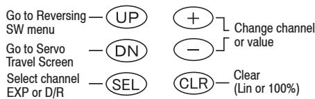
Press the Up arrow key to access the REVERSING SW menu.
- Press the Down arrow key to access the SERVO TRAVEL SCREEN.
- Press the Down arrow and Select keys simultaneously to exit the DUAL RATE AND EXPONENTIAL mode.
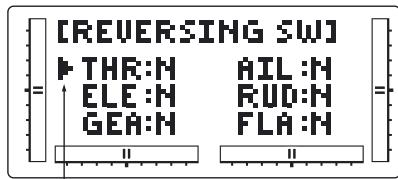
Servo Reversing
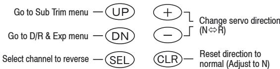
Channel being programmed
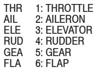
The Reverse Switch function is an electronic means of reversing the throw of a given channel (servo). All six channels of the mx-12 offer reversible servo direction. This will ease setup during the servo installation into your aircraft.
Accessing the Travel Adjust Function
- Place the transmitter power switch in the ON position.
- Access the Function mode by pressing the Down and Select keys simultaneously.
Function mode AIRPLANE
Sub Trim; Travel Adjust
- Press either the Up or Down key until TRAVEL ADJ appears in the upper portion of the LCD.
- Using your transmitter's control sticks, switches and potentiometers, move the control surfaces of your aircraft. Note the travel direction of each of the corresponding control surfaces.
- After you have determined which channel(s) need to have the throw directions reversed, use the Select key to call up the appropriate channel.
- Press either the (+) or (-) keys to change the travel directions of the servo. Pressing the Clear key returns the travel direction to Normal.
- You can observe the change in the travel direction by moving the appropriate control at this time.
- Access the D/R & EXP function by pressing the Down key.
- Access the SUB TRIM function by pressing the Up key.
- Exit the SERVO REVERSING function by pressing the Down and Select keys simultaneously.
Sub Trim
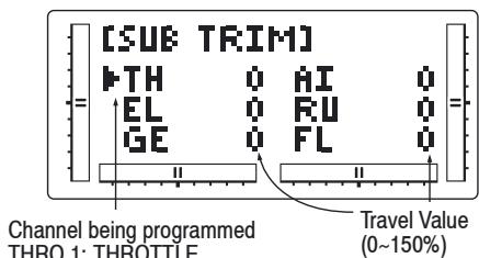
AIL 2:AILERON
ELE 3:ELEVATOR
RUD 4: RUDDER
GEA 5:GEAR
FLA 6:FLAP
The Sub Trim Adjustment function allows you to electronically fine-tune the centering of your servos. Individual
ly adjustable for all six channels with a range of + / - 125% (+ / - 30 degrees servo travel).
The sub trim function provides precise servo arm neutral positioning if rotating the servo arm will not allow the desired servo arm position.
Go to Travel Adjust menu Go to reversing SW menu
Select channel -SEL
CLR—Reset selection to default (Adjust to 0)
Accessing the Sub Trim Function
- Place the transmitter power switch in the ON position.
- To Access the Function mode, press the Down and Select keys simultaneously.
- Press either the Up or Down key until SUB TRIM appears in the upper middle portion of the LCD.
- Press the Select key until the desired channel appears.
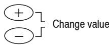
- Press the (+) or (-) key to establish the desired amount and direction of Sub Trim.
Caution: Do not use excessive Sub Trim adjustments since it is possible to overrun your servo's maximum Sub Trim. Remember that it is a trim convenience function. It is not intended to take the place of the proper mechanical trim adjustments that are necessary on any RC model.
- Access the REVERSING SW function by pressing the Down key.
- Access the TRAVEL ADJ function by pressing the Down key.
- Exit the SUB TRIM function by pressing the Down and Select keys simultaneously.
Travel Adjust
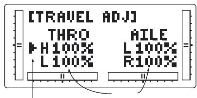
Channel being programmed
THRO 1: THROTTLE
AIL 2: AILERON
ELE 3:ELEVATOR
RUD 4: RUDDER
GEA 5:GEAR
FLA 6:FLAP
The purpose of Travel Adjust is to offer you precise servo control deflection in either direction of servo operation. The mx-12 offers travel adjust for all six channels. The Travel Adjust range is from 0-150% (0 degrees to 60 degrees) from neutral, or center, and it can be adjusted for each direction individually. The factory default (Data Reset) value is 100% for each direction of servo travel.
Go to Sub Trim menu - DN

Reset value to Normal (Adjust to 100%)
Select channel to -SEL Adjust

Reset value to Normal (Adjust to 100%)
Accessing the Travel Adjust Function
- Place the transmitter power switch in the ON position.
- Access the Function mode by pressing the Down and Select keys simultaneously.
- Press either the Up or Down key until TRAVEL ADJ appears in the upper portion of the LCD.
- Press the Select key until the desired channel is
Function mode AIRPLANE
Elevator to flap mixing; Aileron to rudder mixing
highlighted.
- Move the appropriate control stick (lever, switch, etc.) to the right or left of center to the direction of travel you want to adjust. An arrow to the left of the travel adjust value will reflect the current position to be adjusted.
- After the control stick or switch is placed in the direction of travel to be adjusted, press the (+) or (-) key until the proper amount of servo travel is shown on the LCD. Press the (+) key to increase the amount of servo travel. Press the (-) key to decrease the amount of servo travel.
- Follow the same procedure for the remaining channels.
- Access the SUB TRIM function by pressing the Down key.
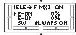
- Access the ELE → F MX function by pressing the Up key.
- Exit the TRAVEL ADJ function by pressing the Down and Select keys simultaneously.
Elevator to flap mixing
When this system is active and a value of flaps is input, the flaps will be deflected each time the elevator stick is used. The actual flap movement is adjustable for both up and down elevator. A switch can be assigned to turn the elevator to flap mixing on or off.
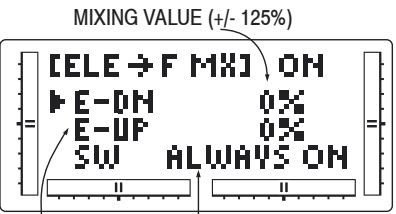
Elevator Operating Direction
E-DN: Down side
E-UP: Up side
Mixing SW Selection
SW Display
ALWAYS ON: Always Mixing In
RIGHT FWD: Gear SW Forward
side → 0n
RIGHT REA: Gear SW Rear side → On
LEFT FWD: FLAP SW Forward side → On
LEFT REA: FLAP SW Rear side → On
AILE D/R: AILE D/R SW Position 1→ On
ELEV D/R: ELEV D/R SW Position 1→On
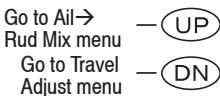

Change value/Select switch
Change selection -SEL

Reset selection to Default (adjust to 0% or ALWAYS ON)
Accessing the Elevator to Flap Function
- Place the transmitter power switch on the ON position.
- Access the Function mode. To do so, press the Down and Select keys simultaneously.
- Move the elevator stick in the direction you want to mix with flaps.
Note: The position indicator will reflect this change by highlighting the up or down arrow.
- Press the (+) or (-) key to increase or decrease the amount of flaps to be mixed. If you want to reverse the flap travel, press the Clear key, bringing the mixing value to the factory default (0%) , and increase the value using the opposite key (+) or (-) from the key originally selected.
- Once you have adjusted the first mixing position (up or down), place the elevator stick in the opposite direction and follow Step 5 above to adjust the second elevator mixing value.
- Access the switch position by pressing the Select key. Use the (+) or (-) keys to select from the one of six switches, or from always on.
- Access the TRAVEL ADJ function by pressing the
Up key.
- Access the AIL → RUD MIX Mixing function by pressing the Up key.
- Exit the ELE → F MX function by pressing the Down and Channel keys simultaneously.
Aileron to rudder mixing
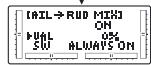
This form of mixing is designed so that when input to the aileron stick is given, the rudder servo will also move, eliminating the need to coordinate these controls manually. When adjusting, if an opposite mixing direction of the rudder servo is required, simply press the (+) or (-) keys to change the mixing value from a (+) or (-) . This will reverse the mixing direction of the rudder from its original direction. The switch used to activate this mix can also be selected as explained below. The factory default is a value of 0%
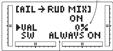
MIXING VALUE (+/- 125%)
Mixing SW Selection
SW Display
ALWAYS ON: Always Mixing In
RIGHT FWD: Gear SW Forward side → On
RIGHT REA: Gear SW Rear side → On
LEFT FWD: FLAP SW Rear side → On
LEFTREA: FLAP SW Rear side → On
AILE D/R: AILE D/R SW Position 1→On
ELEV D/R: ELEV D/R SW Position 1→On
Go to Throttle cut -UP menu
Change value/Select switch

Reset selection to Default (Adjust to 0% or ALWAYS ON)
Accessing the Aileron to Rudder Mixing Function
- Place the transmitter power switch in the ON position.
- Access the Function mode. To do so, press the Down and Select keys simultaneously. Press either the Up or Down key until AIL → RUD MIX appears in the center portion of your LCD.
- Press the (+) or (-) key to increase or decrease the amount of rudder to be mixed with aileron. If you want to reverse the Rudder Mix direction, press the Clear key, bringing the mixing value to the factory default (0%) , and increase the value using the opposite key (+) ir (-) from the key originally selected.
- Press the Select key to access the switch assignment function.
- Press the (+) or (-) key to select the desired switch/ function to activate the Aileron-to-Rudder Mixing function.
- Access the ELE → FLP MX mixing function by pressing the Down key.
- Access the THRO CUT function by pressing the Up key.
- Exit the AIL → RUD MIX function by pressing the Down and Select keys simultaneously.
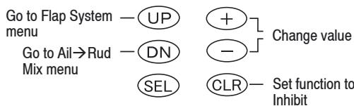
Throttle Cut switch
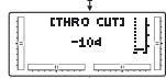
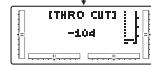
This function assigns the Throttle Cut switch to the push button located on upper right front of the transmitter. The Throttle Cut function is designed to return the throttle trim to the lowest position instantly and keep this position while the button is pressed. This feature is used to "cut" or stop the engine without changing the position of digital throttle trim.
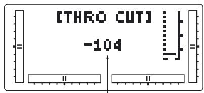
Throttle cut operating position (-32--128)
Accessing the Throttle Cut Function
- Place the transmitter power switch on the ON position.
- Access the Function mode. To do so, press the Down and Select keys simultaneously. Press either the Up or Down key, until THRO CUT appears in the upper portion of the LCD screen.
- Use the (+) and (-) keys to change the value of the Throttle cut function.
Note: Pressing the Clear key will Inhibit the Throttle Cut, turning it off until it has been reactivated.
-
Access the FLAP SYSTEM mixing function by pressing the Down key.
-
Access the AIL → RUD MIX function by pressing the Up key.
- Exit the THRO CUT function by pressing the Down and Select keys simultaneously.
Flap System
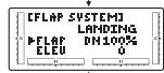
The Flap System function provides elevator compensation to counteract any pitch tendencies when flaps are deployed.
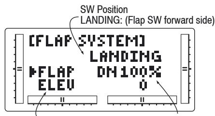
Elevator Offset value
Travel value (DN200~0~UP200)
Flap operating value Travel value (DN125%~0%~UP125%)
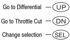
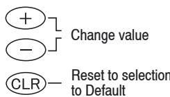
Accessing the Flap System Function
- Place the transmitter switch in the ON position.
- Press the Down and Select keys simultaneously to enter the Function mode.
- Press either the Up or Down key until FLAP SYS-TEM appears in the top of the LCD.
- Press the Select key to select the desired channels to be adjusted.
- Use the (+) or (-) keys to set the desired landing mode surface positions.
- Access the THRO CUT mixing function by pressing
Function mode AIRPLANE
Differential aileron mixing; Programmable Mixing (1~4)
the Down key.
- Access the MIX 1 function by pressing the Up key.
- Exit the FLAP SYSTEM function by pressing the Down and Select keys simultaneously.
Differential aileron mixing
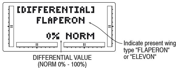
In order to use the Differential Function, flaperon or ele- von (Delta), wing mixing must be selected in the Model Set-Up Mode and two servos must be used to operate the ailerons (one on each). In the Function Mode, use the UP or DN key to select Differential Aileron Mixing and access by pressing the UP and DN keys simultanously.
Note: The Differential Aileron Mixing Function will only be shown in the Function Model if either Flaperon or Delta wing types have been previously selected in the System Mode.
To Program Mixing
To flap system


Differential Value Increases or Decrease

Press to reset Differential Value to factory pre set. (NORM 100%
Differential Value
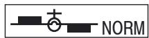
0%

50%
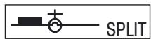
100%
Programmable Mixing (1~4)
The mx-12 offers four programmable mixes to be used for any number of different purposes. This function allows mixing any one channel to any other channel. This mix can remain on at all times or be switched on and off in flight using a number of different switches.
Mix numbers 1-3 are of the standard variety, in that the digital trim for the master channel only affects the master channel, and not the slave channel. Mix number 4 is of the "Trim Include" variety. This mix is used any time the mix requires the slave channels trim position to be varied when the master channels digital trim position is varied. An example for this type of mix would be when dual elevator or dual aileron servos are used and connected to two separate channels of the system, rather than using a single channel with a Y-harness.
Each channel of this radio is identified by an abbreviated name. The chart below indicates the channel and its corresponding abbreviation. The channel name appearing first is known as the "master channel" or the channel to which you want to mix. The second number is known as the "slave channel" or the channel that is being mixed into the master channel. For example, AIL → RUD would indicate aileron-to-rudder mixing. Each time the aileron stick is moved, the aileron will deflect, and the rudder will automatically move in the
direction and to the value input. Mixing is proportional, so small inputs of the master channel will produce small outputs of the slave channel. Each programmable mix has a mixing "offset". The purpose of the mixing offset is to re-define the neutral position of the slave channel.
Accessing the Programmable Mixing Function
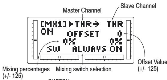
SWITCH
ALWAYS ON: Always Mixing On
RIGHT FWD: Gear SW Forward side → On
RIGHT REA: Gear SW Rear side → On
LEFT FWD: FLAP SW Forward side → On
LEFT REA: FLAP SW Rear side → On
AILE D/R: AILE D/R SW Position 1→ On
ELEV D/R: ELEV D/R SW Position 1→On
Go to Fail Safe menu


Change selected value
Go to Differential


Reset selection to default
Change highlighted selection


Reset selection to default
Accessing the Programmable Mixing Function
- Place the transmitter switch in the ON position.
- Press the Down and Select keys simultaneously to enter the Function mode.
- Press either the Up or Down key until MIX 1 appears in the LCD.
Selecting the Master and Slave Mixing Channels
- Press the (+) or (-) keys to select the master channel.
- Press the Select key to move the cursor to the slave channel position.
- Press the (+) or (-) keys to select the slave channel.
- Press the Select key once. The display will continue to show the current mixing channels at the top of the LCD, but now an arrow will indicate the current stick position (master) to be adjusted.
Setting the Mixing Values
- While holding the master stick in the direction you want to mix, press the (+) or (-) keys to increase or decrease the mixing value for the slave channel. The value in the LCD will change to display the current mix value selected. Next, hold the master stick to the other side to adjust the mix for the other direction.
Setting the Mixing Switch Activation
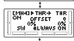
- Press the Select key until the SW is highlighted. The LCD with "ALWAYS ON" indicates the current switch that this mix is currently selected to always be active (ON).
Mixing Operation and Switches
Each mixing program can be turned on and off by a lever or switch. The levers and switches that can be selected for program mixing are tabulated at the right with their abbreviations appearing on the display and their corresponding positions.
Setting the Mixing Channel Offset
- Press the Select key until offset is highlighted. The display will show the current mixing channels at the top of the LCD, with the word "OFFSET" in the center of the LCD. The value to the right is the mixing Offset neutral point, currently 0.
- A new value for the offset can be selected using the (+) or (-) keys. This is the new neutral point for the slave channel (Point that the mix is activated). Press the Clear key to reset the value back to 0.
- Press the Down and Select keys simultaneously to exit the Programmable Mix function.
With a little practice, programmable mixing will become easier to understand. Mixing is inlly limited by your imagination.
Fail Safe
The Fail Safe/Hold function is available only when you use the mx-12 transmitter in PCM modulations. This function is designed to help minimize damage to your aircraft during a loss of signal to the receiver. The servos either assume the fail-safe presets or hold their last good signal position.
As noted earlier, if you are in the PPM modulation, the Fail-Safe/Hold function is not applicable. Therefore, the Fail-Safe/Hold function will not appear on your LCD screen menu while in the PPM mode. Refer to the Modulation Selection section for more information pertaining to the broadcast signal of your mx-12 transmitter.
Note: The throttle fail safe position is defaulted to the idle position for added safety.
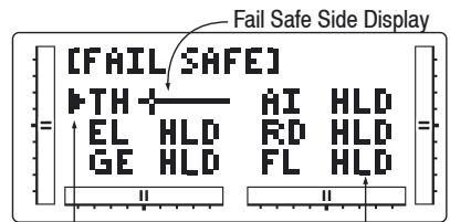
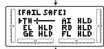
Channel being programmed
TH Throttle RU Rudder
AI Aileron GE Gear
EL Elevator FL Flap
Hold Side Setup Display
Go to Servo Travel -UP + Change from servo Screen
Go to Programab- DN hold to stick selection le Mixing menu (F.S. ⇔ HOLD) Change highlighted -SEL CLR -Invoke stick selection selection
Accessing the Fail Safe Function
- Place the transmitter power switch in the ON position.
- Access the Function mode. To do so, press the Down and Select keys simultaneously. Press either the Up or Down key until FAIL SAFE appears in the upper portion of the LCD screen.
- Use the Select key to highlight the servo function to set.
- Use the (+) or (-) keys to toggle between servo hold or setting the servo position.
- When using the servo setting position, move the corresponding control stick to the position where you want the servo if the radio enters into the fail safe mode. Press the Clear key to have the transmitter memorize all stick position.
- Repeat steps 4 and 5 until all six controls have been set.
- Access the SERVO TRAVEL screen by pressing the
Function mode AIRPLANE
Servo Travel Screen
Up key.
- Access the MIXING FUNCTIONS function by pressing the Up key.
- Exit the FAIL SAFE function by pressing the Down and Select keys simultaneously.
Servo Travel Screen
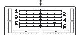
The Servo Travel Screen is used to verify the stick movements of the transmitter. It can also be used to verify the mixing functions have been performed correctly without the need to turn on the aircraft.
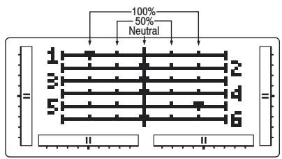
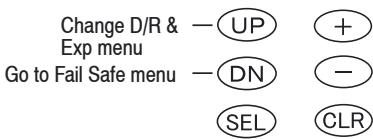
Accessing the Servo Travel Screen
- Place the transmitter power switch in the ON position.
- Access the Function mode. To do so, press the Down and Select keys simultaneously. Press either the Up or Down key until the SERVO TRAVEL screen appears.
- Move the sticks. The indicators correspond to the following:
Indicator 1: Throttle
Indicator 2: Aileron
Indicator 3: Elevator
Indicator 4: Rudder
Indicator 5: Gear
Indicator 6: Flap
- Access the D/R & EXP screen by pressing the Up key.
- Access the FAIL SAFE function by pressing the Up key.
- Exit the SERVO TRAVEL screen function by pressing the Down and Select keys simultaneously.
Function mode HELICOPTER
Dual Rate and Exponential; Servo Reversing
Dual Rates and Exponential
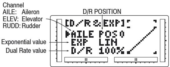
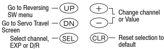
Dual rates are available for the aileron, elevator and rudder channels of your RC aircraft.
Dual rates may be defined as the ability to vary the travel or throw rate of a servo from a switch. Due to the differing travel rates, you will find that the sensitivity of the control either increases or decreases accordingly. A higher rate, or travel, yields a higher overall sensitivity. You may find it easier to think of the Dual-Rate function as double-rates or half-rates.
The amount of travel is adjustable from 0-125% in 1% increments. The factory setting, or default value, for both the 0 and 1 switch positions is 100% .
Exponential reduces the sensitivity in the middle portion of stick movement, while still allowing full travel at the end of the stick movement. The end result (travel) remains the same, although exponential changes the rate at which it achieves this travel. The adjustable range is from 0-100%. Zero percent (0%) is linear stick control, meaning the response rate is equal throughout the stick control. 100% is full exponential. The larger the expon
ential value, the less servo action or sensitivity you will notice around the neutral setting.
Either switch position may be selected as the low or high rate by placing the switch in the desired position and adjusting the value accordingly.
Accessing the Dual Rate and Exponential Function
- Place the transmitter power switch in the ON position.
- Access the Function mode by pressing the Down and Select keys simultaneously.
- Press either the Up or Down key intil D/R & EXP appears in the upper left corner of the LCD.
- Press the (+) or (-) key until the desired channel (aileron) elevator or rudder) appears.
- Select the switch position for which you want to adjust the rate. The number to the upper right of the current rate value on the display indicates the current position of the Dual-Rate switch for the channel that you have selected. Either a 0 or a 1 will be shown, corresponding to the position of the switch. To select the opposite switch Rate switch to the opposite position. The number that appears above the current rate value reflects the change.
- Adjust the rate for the channel and the switch position just selected. To decrease the throw rate, move the cursor to the D/R position using the Select key, then press the (-) key. To increase the throw rate, press the (+) key. As stated previously, the adjustable rate is from 0-125% for each switch position and channel.
- Press the Up arrow key to access the REVERSING SW menu.
-
Press the Down arrow key to access the SERVO TRAVEL SCREEN.
-
Press the Down arrow key to access the SERVO TRAVEL SCREEN.
- Press the Down arrow and Select keys simultaneously to exit the DUAL RATE AND EXPONENTIAL mode.
Servo Reversing
The Reverse Switch function is an electronic means of reversing the throw of a given channel (servo). All six channels of the mx-12 offer reversible servo direction. This will ease setup during the servo installation into your helicopter.
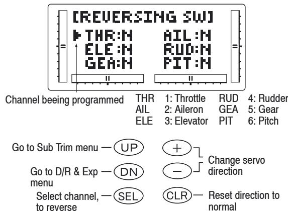
Accessing the Servo Reverse Function
- Place the transmitter switch in the ON position.
- Access the Function mode by pressing the Down and Select keys simultaneously.
- Press either the Up or Down key until the REVER-SING SW appears in the upper portion of the LCD.
- Using your transmitter's control sticks, switches and potentiometers, move the control surfaces on your aircraft. Note the travel direction of each of the
Function mode HELICOPTER
Sub Trim; Travel Adjust
corresponding control surfaces.
- After determining which channel(s) need to have the throw directions reversed, use the Select key to call up the appropriate channel.
- Press either the (+) or (-) keys to change the travel direction of the servo. Pressing the Clear key returns the travel direction to Normal.
- You can observe the change in the travel direction by moving the appropriate control at this time.
- Access the D/R & EXP function by pressing the Down key.
- Access the SUB TRIM function by pressing the Up key.
- Exit the SERVO REVERSING function by pressing the Down and Select keys simultaneously.
Sub Trim
The Sub Trim Adjustment function allows you to electronically fine-tune the centering of your servos. Individually adjustable for all six channels with a range of +/-125% (+/- 30 degrees servo travel).
The sub trim functions provide precise servo arm neutral positioning if rotating the servo arm will not allow the desired servo arm position.
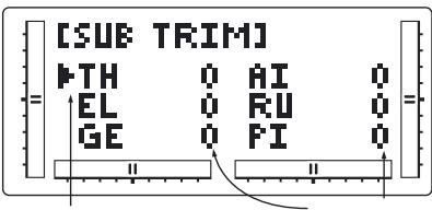
Channel beeing programmed
Sub Trim Value (0 + / - 125)
TH 1: Throttle
AI 2:Aileron
EL 3:Elevator
RU 4: Rudder
GE 5: Gear
PI 6: Pitch
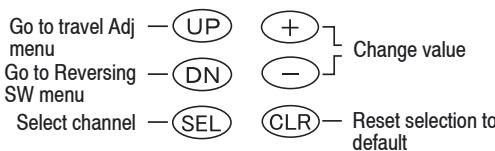
Accessing the Sub Trim Function
- Place the transmitter power switch in the ON position.
- To Access the Function mode, press the Down and Select keys simultaneously.
- Press either the Up or Down key until SUB TRIM appears in the upper middle portion of the LCD.
- Press the Select key until the desired channel appears.
- Press the (+) or (-) key to establish the desired amount and direction of Sub-Trim.
Caution: Do not use excessive sub-trim adjustments since it is possible to overrun your servo's maximum Sub Trim. Remember that it is a trim convenience function. It is not intended to take the place of the proper mechanical trim adjustments that are necessary on any RC model.
- Access the REVERSING SW function by pressing the Down key.
- Access the TRAVEL ADJ function by pressing the Up key.
- Exit the SUB TRIM function by pressing the Down and Select keys simultaneously.
Travel Adjust
The purpose of Travel Adjust is to offer you precise servo control deflection in either direction of servo operation. The mx-12 offers travel adjust for all six channels. The Travel Adjust range is from 0-150% (0 degrees to
60 degrees) from neutral, or center, and it can be adjusted for each direction individually. The factory default (Data Reset) value is 100% for each direction of servo travel.
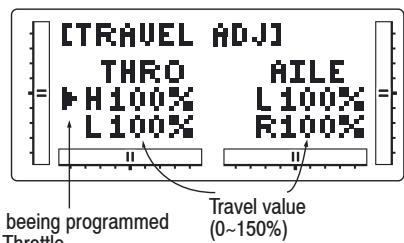
1H 1:Throttle
AI 2:Aileron
EL 3:Elevator
RU 4: Rudder
GE 5: Gear
PI 6: Pitch
Go to Swash Mixing -UP + Change value
or Throttle cut menu
Go to Sub Trim DN - menu Select channel to SEL - Reset value to normal adjust
Accessing the Travel Adjust Function
- Place the transmitter power switch in the ON position
- Access the Function mode by pressing the Down and Select keys simultaneously.
- Press either the Up or Down key until TRAVEL ADJ appears in the upper portion of the LCD.
- Press the Select key until the desired channel is highlighted.
- Move the appropriate control stick (lever, switch, etc.) to right or left of the center to the direction of travel you want to adjust value will reflect the current position to be adjusted
- After the control stick or switch is placed in the dir
ection of travel to be adjusted, press the (+) or (-) key until the proper amount of servo travel is shown on the LCD. Press the (+) key to increase the amount of servo travel. Press the (-) key to decrease the amount of servo travel.
- Follow the same procedure for the remaining channels.
- Access the SUB TRIM function by pressing the Down key.
- Access the THROTTLE CUT function by pressing the Up key.
- Exit the TRAVEL ADJ function by pressing the Down and Select keys simultaneously.
CCPM Swashplate Mixing
The CCPM Swashplate Mixing Function (Cyclic Collective Pitch Mixing) of the mx-12 is designed to be used in model helicopters that utilize 2-servo (180°) , 3-servo (120°) and 3-servo (90°) type swashplate control system.
The desired swashplate mixing type must first be selected at the Swash Type Selection in System Mode.
If the Swashplate Type option has not been selected, proceed to Throttle Cut section.
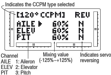
Go to the Throttle Cut -UP + Increase/decrease
menu
Go to the Travel Ad- DN -value or change
justment menu reversing value
Return highlighted -SEL CLR Return highlited
value to default value to default
Note: The CCPM Swashplate Mixing screen is only displayed when Swashplate types 2Serv, 3Serv, or 4Serv CCPM are selected in the Swashplate type Selection in System Mode.
Accessing the Swashplate Type
- Place the transmitter power switch in the ON position.
- Access the Function Mode by pressing the Down and Select keys simultaneously.
- Press either the Up or Down key until 90° CCPM, 120° CCPM or 180° CCPM appears in the middle left portion of the LCD.
Note: The swashplate type selection is selected in the System mode on Page XX.
- Press the Select key until the desired function is highlighted.
- Press the (+) or (-) Keys to Increase or Decrease the CCPM Values.
- Follow the same procedure for the remaining channels.
- Access the TRAVEL ADJ function by pressing the Down key.
- Access the THROTTLE CUT function by pressing the Up key.
- Exit the CCPM SETUP screen by pressing the Down and Select keys simultaneously.
CCPM is a type of pitch mixing where the two or three servos are connected directly to the swashplate of the
helicopter and physically move together and independently for all changes in pitch/cyclic. Please refer to the diagram below.
CCPM Servo Variations
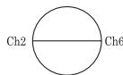
2 Servo/180°CCPM
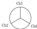
3 Servo/120° CCPM
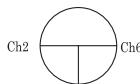
Ch3 3 Servo CCPM
(Graupner style, most popular)
1.) One servo (Standard Mechanical Miying)
The most common form of Swashplate Mixing.
This type uses each of the three servo to move the swashplate individually for pitch, Aileron and Elevator changes. If one servo (NORM) is selected in the System Mode (Factory Default), the Swashplate Type Function will not appear on the LCD screen in this section.
2.) Two servo (180-degrees)
Two servos are used to move the swashplate, and are spaced at 180 degrees apart. This is not a very common control system configuration.
3.) Three servo (120-degrees)
Three servos are used to move the swashplate, and are spaced at 120 degrees apart. This is the most common form of CCPM, and is found in Graupner and other brands of Helicopters.
4.) Three servo (90-degrees)
Three servos are used to move the swashplate, and are spaced at 90 degrees apart. This is also not a very common control system configuration.
CCPM Servo Connection/Channel Numbers
2 servo (180°)
Ch2 = Aileron
Ch2 = Elevator
Function mode HELICOPTER
Throttle Cut Switch; Throttle Hold
Ch6 = Pitch
3 servo (120°)
Ch2 = Aileron
Ch2 = Elevator
Ch6 = Pitch
Throttle Cut Switch
This function assigns the Throttle Cut switch to the push button located on upper right front of the transmitter. The Throttle Cut function is designed to return the throttle trim to the lowest position instantly and keep this position while the button is pressed. This feature is used to "cut" or stop the engine without changing the position of digital throttle trim.
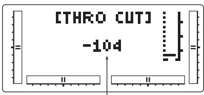
Throttle Cut Operating position (-32--128)
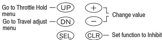
Accessing the Throttle Cut Function
- Place the transmitter power switch in the ON position.
- Access the Function mode. To do so, press the Down ans Select keys simultaneously. Press either the Up or Down key until THRO CUT appears in the upper portion of the LCD screen.
- Us the (+) and (-) keys to change the value of the
Throttle cut function.
Note: Pressing the Clear key will Inhibit the Throttle Cut, turning it off until it has been reactivated.
- Access the TRAVEL ADJ mixing function by pressing the Down key.
- Access the THROTTLE HOLD function by pressing the Up key.
- Exit the THRO CUT function by pressing the Down and Select keys simultaneously.
Throttle Hold
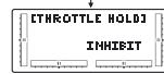
The Throttle Hold function is designed to hold the throttle servo in a specific position during an autorotation. This is very useful for practicing autorotation landings. The throttle hold switch can be programmed to one of the four toggle switches. Throttle hold will always be "On" in the forward switch position and "Off" in the rear position.
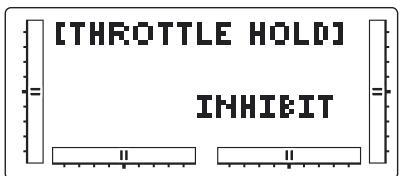
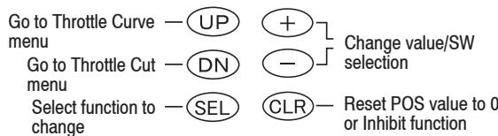
Press + / - key
Press CLR key during selecting SW
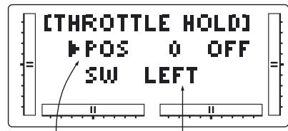
Throttle Hold Position (-20~50)
Hold SW Select
Switch
LEFT :THRO HOLD SW Forward Side → On
AILE D/R : AILE D/R: AILE D/R SW Position 1→On
ELEV D/R: ELEV D/R Position 1 → 0
RIGHT :FLIGHT MODE SW Forward Side → On
Accessing the Throttle Hold Function
- Place the transmitter power switch in the ON position.
- Press the Down and Select keys simultaneously to enter the Function mode.
- Press either the Up or Down key until THROTTLE HOLD appears across the top of the LCD.
- The factory setting for the throttle hold is inhibit. Pressing either the (+) or (-) key will activate Throttle Hold and display the current throttle hold value.
- Using the (+) or (-) key, adjust the throttle hold value to deliver the proper engine idle rpm for your helicopter. The adjustable range is (-20% -1 + 50%) . Once you establish the proper idle value for your engine, you can use this value for throttle hold as well. To shut the engine off for autorotation, a negative or zero value should be input.
Note: When the throttle hold is activated, and the switch is on, the indicator on the LCD will change from Off to On. In addition, the throttle trim indicator will be inhibited.
- Access the THROTTLE CURVE function by pressing the Up key.
Function mode HELICOPTER
Throttle Curves
- Access the THROTTLE CUT function by pressing the Down key.
- To exit the THROTTLE HOLD function, press the Down and Select keys simultaneously.
Throttle Curves
The mx-12 offers two (2) separate throttle curves with five adjustable points per curve. This function allows you to customize the throttle curve and pitch curve together to maximize engine performance at a particular pitch setting. Once the throttle curves are established, each can be activated in flight using the two (2) position flight mode switch.
The flight mode switch offers two selectable ranges: Normal and Stunt. The Normal position should be used as the hover throttle curve. The Stunt position should be used for aerobatic maneuvers and forward flight.
Note: The throttle trim and hovering throttle levers are only operable when the flight mode switch is in the normal position. Thus, in normal function it will have no effect. Also, adjusting the hovering throttle lever and throttle trim has no effect on the input values of the throttle curve.
Each of the five points of the throttle curve are independently adjustable from 0 - 100% . These five points correspond to the position of the throttle stick. The illustration below shows the normal throttle curve setting for the dead slow position with throttle trim at default.
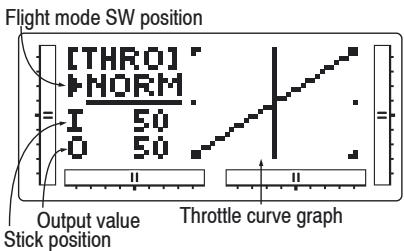
Go to Pitch Curve—UP + Change value/Switch menu
Go to Throttle Hold—DN - selection
menu
Press to access the — SEL CLR Rest value to 0 or P-LOW, P-1, P-MID, P-3 and P-HIGH
curve points
Set function to inhibit
The transmitter is factory preset to the throttle curve as indicated by the solid line in the figure at right. Individual middle points can be increased or decreased to suit your specific needs.
The throttle trim lever position will affect the low-point position as shown when in the Normal mode Throttle Curve.
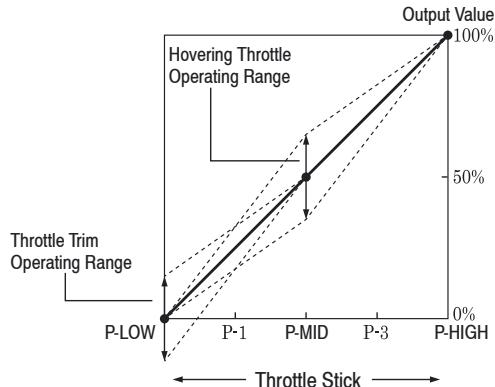
Accessing the Throttle Curve Function
- Place the transmitter power switch in the ON position.
- Press the Down and Select keys simultaneously to enter the Function mode.
- Press either the Up or Down key until THRO appears in the upper portion of LCD.
Note: Use NORM for hover curves and STUNT for aerobatics. We will concentrate on the hovering curve during this example.
- Press the Select key to select the point of the curve you want to change.
- Press either the (+) or (-) key to change the value of the current curve point. The range of each point is 0-100% in 0,5% intervals.
Note: In each curve, the factory setting indicates INH for points 1 and 3. These values are 25% and 75% respectively if no value changes are made to any other points. If any of the other points have been changed while these points were inhibited, the inhibited points will also change to plot a smooth curve. If you want to keep this from happening, press the Select key until the display indicates P-1 or P-3 at the upper right portion of the LCD. Press either the (+) or (-) key to activate the points 1 (25%) or 3 (75%). The values for each of these curves can then be fully adjusted by pressing either the (+) or (-) key.
- To set curves for STUNT mode, press the Select to highlight the NORM function, then press the (+) or (-) key to select the STUNT function. Repeat Steps 4 and 5 to complete the procedure.
- Access the PITCH CURVE function by pressing the Up key.
- Access the THROTTLE HOLD function by pressing the Down key.
- Exit the THROTTLE CURVE function by pressing the Down and Select keys simultaneously.
Throttle Time Settings
The throttle trim lever is only active when the flight mode switch is in the normal position. The throttle trim is used to increase or decrease the engine power when the flight mode switch is in the Normal mode. The throttle
Function mode HELICOPTER
Pitch Curves
trim lever has no effect on positions 1 or throttle hold.
Note: Making changes to the throttle trim lever does not change the input values for any of the points on the throttle curve; it merely makes adjustments to the engine idle speed position.
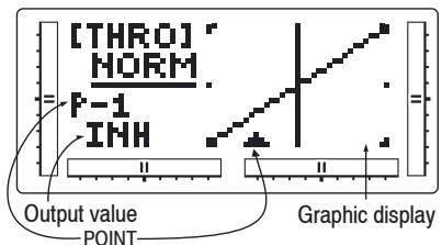
P-LOW : Full Slow position
P-3 : Stick 3/4 position
P-1 : Stick 1/4 position
P-HIGH : Full High position
P-MID : Stick Center position
- Point position is fixed
Hovering Throttle Lever Settings
The Hovering Throttle lever increases or decreases the engine output power for the middle three points set for the middle three points set for the throttle curve. As shown in the figure below, use of the hovering throttle lever shifts the curve upward or downward parallel with the original curve. Therefore, operation of the hovering throttle knob does not cause any change to the original settings of the throttle curve.
The throttle trim range will affect the throttle curve as shown.
The adjustable range of output using the hovering throttle lever is approximately + / - 9%
Note: The Hovering Throttle has no effect on flight mode switch position 1.
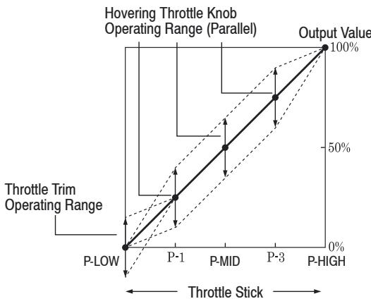
Pitch Curves
Adjustment of the pitch curve is very similar to the throttle curve adjustment described in the preceding section. A thorough understanding of the Throttle Curve Section will make pitch curve adjustment easier to understand. There are three independent types of pitch curves available: Normal, Stunt, and Hold. Each pitch curve contains five adjustable points: LOW 1, MID 3, and HIGH.
Note: The pitch curve for the Throttle Hold function can only be set if this system is activated.
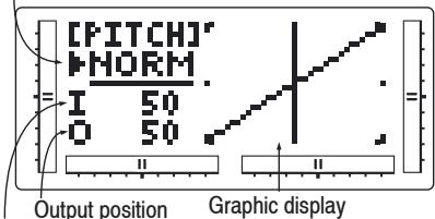
Flight Mode SW position
Stick position
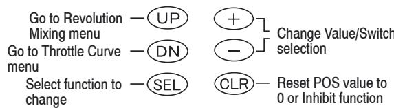
Accessing the Pitch Curve Function
- Place the transmitter power switch in the ON position.
- Press the Down and Select keys simultaneously to enter the Function mode.
- Press either the Up and Down key until PITCH appears in the top of the LCD.
Note: Use NORMAL for hover curses and STUNT for stunt curves. We will concentrate on the hovering curve during this example.
- Press the Select key to select the point of the curve you want to change.
- Press either the (+) or (-) key to change the value of the current curve point. The range of each point is 0-100% in 0.5% intervals.
Note: In each curve, the factory setting INH indicates Inhibited for points 1 and 3. These values are 25% and 75% respectively, if no value changes are made to any other points. If any of the other points have been changed while these points were inhibited, the inhibited points will change to plot a smooth curve. If you want to keep this from happening, press the Select key to display the positions 1 and 3, then press the (+) or (-) key to activate each point.
- To set curves for STUNT mode, press the Select to highlight the NORM function, then press the (+) or (-) key to select the STUNT function, Repeat Steps 4 and 5 to complete the procedure.
- To set the curves for the Throttle Hold mode "H",
press the Up key once again until "H" is displayed, and repeat steps 4 and 5.
- Access the REVO MX function by pressing the Up key.
- Access the THROTTLLE CURVE function by pressing the Down key.
- Exit the PITCH CURVE function by pressing the Down and Select keys simultaneously.
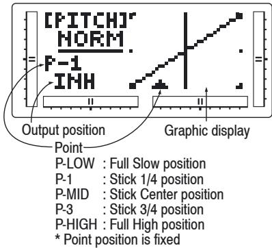
Hovering Pitch Lever
The Hovering Pitch lever operates in the same manner as the Hovering Throttle lever. It is only operable while the flight mode switch is in the NORMAL position, and its function is to shift the middle portion of the curve upward or downward.
Example of Throttle Curve and Pitch Curve Settings An example of throttle curve and pitch curve settings for aerobic specifications is shown below in the form of graphs. Details of the curves will differ depending on the helicopter specifications. In these examples, the throttle open-close stroke and autorotation pitch stroke are set 0 to 100 to ease your understanding of other curves.
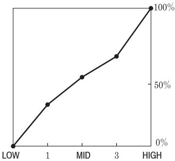
Throttle

Normal Hover
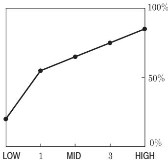
Pitch
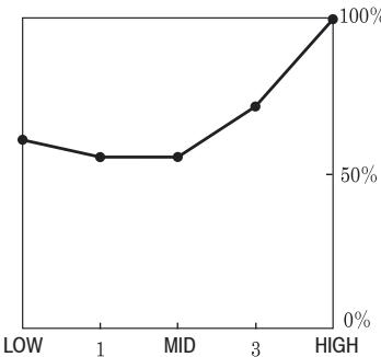
Throttle

Stunt 1 Aerobatics
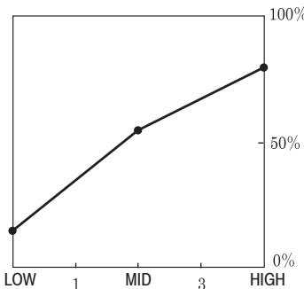
Pitch

rotll

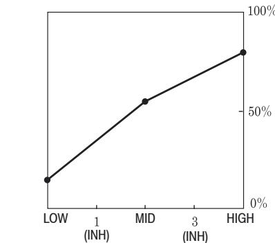
Pitch
Function mode HELICOPTER
Revolution Mixing (Non-heading lock Gyros only), Programmable Mixing (1~2)
Revolution Mixing (Non-heading lock Gyros only)
The Revolution Mixing function mixes tail rotor with the Throttle and Pitch Curve functions to counteract torque from the main rotor blades. When set up correctly, the helicopter should climb and descend without a tendency to yaw in either direction. Because torque reaction varies with different power settings, it is necessary to vary the tail rotor pitch at the same time. The mx-12 offers two separate revolution mixing programs, with independent up and down mixing for each - one for Flight mode position Normal and the other for Stunt. The up mixing adjusts the tail rotor compensation for the mid to high throttle setting and the down mixing adjusts the tail rotor compensation for the mid to low throttle setting.
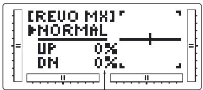
Mixing Value (L125%~0~R125%)
Mixing Program
NORMAL
UP: Up side
DN: Dow
STUNT
UP: Up side
DN: Down side
Go to Programmable
Mixing menu
Go to Pitch curve
menu
Highlight function to
change


Change value/
Switch selection
Reset selection to
default
Accessing the Revolution Mixing Function
- Place the transmitter power switch in the ON position.
- Press the Down and Select keys simultaneously to enter the Function Mode.
- Press the Up or Down keys until REVO MX ap
pears at the top of the LCD.
- Pressing the Select key will highlight either the Up mix, Down mix, or the flight mode switch position. When the flight mode switch is in the displayed position and the throttle stick is in the displayed position, the flight mode will be underlined.
- Press the (+) key to increase the right tail compensation or press the (-) key to increase the left compensation. Press the Clear to reset to 0% .
- This setup procedure can be used for revolution mixing for either flight mode switch position Normal or Stunt. The Stunt position should be used for forward and/or inverted compensation.
- Access the PITCH CURVE function by pressing the Down key.
- Access the MX1 function by pressing the Up key.
- Exit the REVO MX function by pressing the Down and Select keys simultaneously.
Setting Up Revolution Mixing (non-heading lock, gyros only)
Set up the helicopter so that it will hover with the tail rotor trim entered. Establish the helicopter into a stable hover, then steadily increase the throttle to initiate a steady climb. The body of the helicopter will move in the opposite direction to the main rotor rotation. Increase the U, Up, setting until the helicopter climbs with no tendency to turn. At a safe altitude, close the throttle; the helicopter will same direction as the main rotor rotation. Increase the D, or Down, mix until the helicopter descends with no tendency to turn. Throttle stick movements should be slow, and the initial acceleration and deceleration swings should be ignored. The Accerlation Mixing function is provided to compensate for the main rotor acceleration (and deceleration) torque.
Programmable Mixing (1~2)
The mx-12 offers two programmable mixes to be used for any number of different purposes. This function allows mixing any one channel to any other channel. This mix can remain on at all times or be switched on and off in flight using a number or different switches.
Mix number 1 is of the standard variety, in that the digital trim for the master channel only affects the master channel, and not the slave channel. Mix number 2 is of the "Trim include" variety. This mix is used any time the mix requires the slave channels trim position to be varied when the master channels digital trim position is varied. Each channel of this radio is identified by an abbreviated name. The chart below indicates the channel ant its corresponding abbreviation. The channel name appearing first is known as the "master channel" or the channel to which you want to mix. The second number is known as the "slave channel" or the channel that is beeing mixed into the master-channel. For example, AIL → RUD would indicate aileron-to-rudder mixing. Each time the aileron stick is moved, the aileron will deflect, and the rudder will automatically move in the direction and to the value input. Mixing is proportional, so small inputs of the master channel will produce small outputs of the slave channel. Each programmable mix has a mixing "offset". The purpose of the mixing offset is to redefine the neutral position of the slave channel.
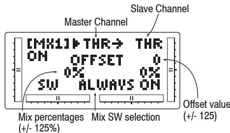
SW display
ALWAYS ON: Always Mixing On
RIGHT FWD: Gear SW Forward side → On
RIGHT REA: Gear SW Rear side → On
LEFT FWD: FLAP SW Forward side → On
LEFT REA: FLAP SW Rear side → On
AILE D/R: AILE D/R SW Position 1→ 0 n
ELEV D/R: ELEV D/R SW Position 1 → 0
Accessing the Programmable Mixing Function
- Place the transmitter power switch in the ON position.
- Press the Down and Select keys simultaneously to enter the Function mode.
- Press either the Up or Down key until MIX 1 appears in the LCD.
Selection the Master and Slave Mixing Channels
- Press the (+) or (-) keys to select the master channel.
- Press the Select key to move the cursor to the slave channel.
- Press the (+) or (-) keys to select the slave channel.
- Press the Select key once. The display will continue to show the current mixing channels at the top of the LCD, but now an arrow will indicate the current stick position (master) to be adjusted.
Setting the Mixing Values
- While holding the master stick in the direction you want to mix, press the (+) or (-) keys to increase or decrease the mixing value for the slave channel. The value in the LCD will change to display the current mix value selected. Next, hold the master stick to the other side to adjust the mix for the other direction.
Setting the Mixing Switch Activation
- Press the Select key until the SW is highlighted. The LCD with "ALWAYS ON" indicates the current switch that this mix currently selected to always be
active (ON).
Mixing Operation and Switches
Each mixing program can be turned on and off by a lever or switch. The lever and switches that can be selected for program mixing are tabulated at the right with their abbreviations appearing on the display and their corresponding positions.
Setting the Mixing Channel Offset
- Press the Select key until offset is highlighted. The display will show the current mixing channels at the top of the LCD, with the word "OFFSET" in the center of the LCD. The value to the right is the mixing Offset neutral point, currently 0.
- A new value for the offset can be selected using the (+) or (-) keys. This is the new neutral point for the slave channel (Point that the mix is activated). Press the Clear key to reset the value back to 0.
- Press the Down and Select keys simultaneously to exit the Programmable Mix function.
With a little practice, programmable mixing will become easier to understand. Mixing is only limited by your imagination.
Fail Safe
The Fail Safe Function is available only when you use the mx-12 transmitter in PCM modulations. This function is designed to help minimize damage to your aircraft during a loss of signal to the receiver. The servos either assume the Fail Safe presets or hold their last good signal position.
As noted earlier, if you are in the PPM modulation, the Fail Safe Function is not applicable. Therefore, the Fail Safe Function will not appear on your LCD screen menu while in the PPM mode. Refer to the Modulation Selection section for more information pertaining to the
broadcast signal of you mx-12 transmitter.
Note: The throttle Fail Safe position is defaulted to the idle position for added safety.
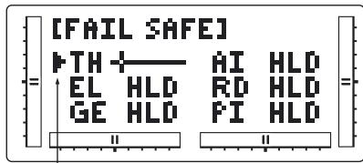
Channel beeing programmed
Accessing the Fail Safe Function
- Place the transmitter power switch in the ON position.
- Access the Function mode. To do so, press the Down and Select keys simultaneously. Press either the Up or Down key until FAIL SAFE appears in the upper portion of the LCD screen.
- Use the Select key to highlight the servo function to set.
- Use the (+) or (-) keys to toggle between servo hold or setting the servo position.
- When using the servo setting position, move the corresponding control stick to the position where you want the servo if the radio enters into the fail safe mode. Press the Clear key to have the transmitter memorize the stick position.
Function mode HELICOPTER
Servo Travel Screen
- Repeat steps 4 and 5 until all six controls have been set.
- Access the SERVO TRAVEL screen by pressing the Up key.
- Access the MIXING FUNCTIONS function by pressing the Up key.
- Exit the FAIL SAFE function by pressing the Down and Select keys simultaneously.
Servo Travel Screen
The Servo Travel Screen is used to verify the stick movements of the transmitter.
It can also be used to verify the mixing functions have been performed correctly without the need to turn on the aircraft.
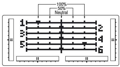
Go to D/R & Exp menu


Go to Fail Safe menu


Accessing the Servo Travel Screen
- Place the transmitter power switch in the ON position.
-
Access the Function mode. To do so, press the Down and Select keys simultaneously. Press either the Up or Down key until the SERVO TRAVEL screen appears.
-
Move the sticks. The indicators correspond to the following:
Indicator 1: Throttle
Indicator 2: Aileron
Indicator 3: Elevator
Indicator 4: Rudder
Indicator 5: Gear
Indicator 6: Pitch
- Access the D/R & EXP screen by pressing the Up key.
- Access the FAIL SAFE function by pressing the Up key.
- Exit the SERVO TRAVEL screen function by pressing the Down and Select keys simultaneously.
System Mode
Model Selection; Model Name Entry
Model Selection
The mx-12 system offers memory for ten completely separate models. Therefore, it is possible to have a mixture of helicopter and airplane setups retained in memory. It is also recommended that the Model Name Entry function be used in conjunction with each model setup. Another very useful function of the Model Selection function is the ability to set one aircraft up several different ways. This is helpful when multi-task performance is desired.
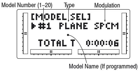
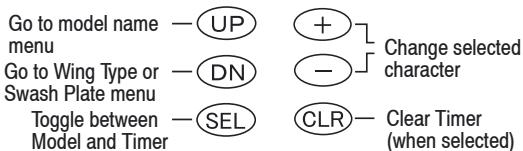
Accessing the Model Select Function
- While pressing the Down and Select keys, switch the transmitter to the ON position to enter the Model select mode.
- Model Select will be displayed on the upper left portion of the LCD. If not, press the Up or Down key until MODEL SEL is displayed.
- Pressing the (+) or (-) key will select among each of the ten models available. Notice that as each model is selected, its name appears in the LCD.
- Once the desired model is displayed on the left,
pressing the Down and Channel keys simultaneously will exit the Model Selection function and establish the model displayed as the new current model.
- Press the Select key to select the timer function to clear the Total Timer. Press the Clear key to clear the Total timer.
- Press the Down key to access the WING TYPE function.
- Press the Up key to access the MODEL NAME function.
- Press the Down and Select keys simultaneously to exit the MODEL SEL function.
Model Name Entry
The mx-12 allows on 8-digit name to be input for each of the ten models available. The current model will be displayed in the Normal display.
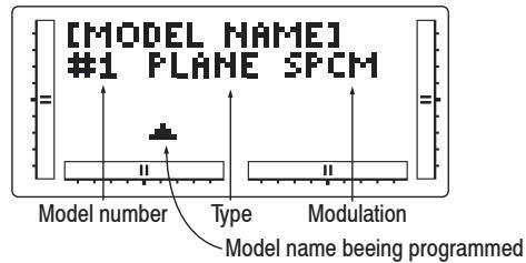
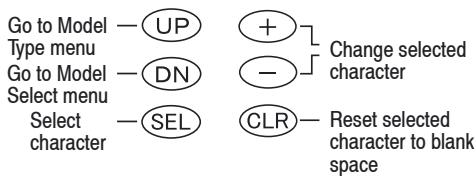
Accessing the Model Select Function
- While pressing the Down and Select keys, switch the transmitter to the ON position to enter the Model
select mode.
- Press the Up or Down key until MODEL NAME is displayed.
- Press either the Up or Down key to select the first character for the model name.
- Press the Select key to advance the character selection to the next character.
- Repeat this procedure until all eight characters have been selected.
- Press the Down key to access the MODEL SEL function.
- Press the Up key to access the MODEL TYPE Selection function.
- Press the Down and Select keys simultaneously to exit the MODEL NAME function.
Selectable character:
!#5%20()+,-,/0123456789:
<=>?A B C D E F G H I J K L M N O P Q R S T
U U W X Y Z [ ]^_10111213141516171819
System Mode
Model Type Selection; Model Copy Function
Model Type Selection
The mx-12 is capable of performing as a helicopter or airplane radio with full functions for each.
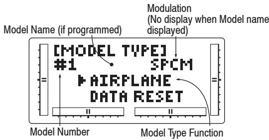
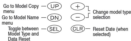
Accessing the Type Selection Function
- While pressing the Down and Select keys, switch the transmitter to the ON position to enter the Model Setup mode.
- Press either the Up or Down keys until MODEL TYPE is displayed in the left portion of the LCD.
- Pressing either the (+) or (-) key will change the type of model.
- Press the Select key to move the cursor to the Data Reset position.
- Press the Clear key to reset the memory to the factory defaults.
- Press the Down key to access the MODEL NAME function.
-
Press the Up key to access the MODEL COPY function.
-
Press the Down and Select keys simultaneously to exit the MODEL TYPE function.
Model Copy Function
The Copy Selection function enables you to copy all of the settings of the current model to another model within the same transmitter. This is very useful when setting up one aircraft several different ways or when trying an alternative setup of your current model.
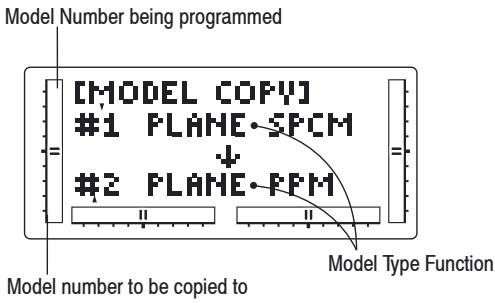
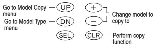
Accessing the Model Copy Function
- While pressing the Down and Select keys, move the transmitter's power switch to the On position.
- Press either the Up or Down key until MODEL COPY appears on the top left of the LCD.
-
The upper number that appears is the current model. This is important to note as only the current model will the copied. Press the (+) or (-) keys to select the desired program (lower number) to copy the current model to.
-
Next, press the Clear key. The current model will then be copied to the selected model.
Note: Always make sure that the accepting model is either free of input or one which you no longer want to retain in your transmitter's memory. Once the copying process has been completed, the information of the accepting model is lost and the current model is input as the new data.
- Press the Up key to access the MODULATION function.
- Press the Down key to access the MODEL TYPE function.
- Press the Down and Select keys simultaneously to exit the MODEL COPY function.
System Mode
Modulation Selection, Stick Mode
Modulation Selection
The Modulation Selection function enables your mx-12 to transmit to a variety of GRAUPNER receivers. You can select from either S-PCM (Pulse Code Modulation) or from PPM (Pulse Position Modulation [=FM]).
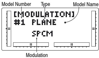
Go to Switch Select -UP + Change trainer mode
menu
Go to Modulation -DN - -
menu
SEL CLR Return to Normal mode
Accessing the Modulation Function
- Move the power switch to the ON position while pressing the Down and Select key to access the System mode.
- Press either the Up or Down key until MODULATION appears at the top of the LCD.
- Press either (+) or (-) keys to change the modulation type.
- Pressing the Clear key will also reset the modulation selection to the factory preset S-PCM.
- Press the Down key to access the MODEL COPY function.
- Press the Up key to access the TRAINER function.
- To exit the MODULATION function, press the Down and Select keys simultaneously.
Note: In the normal display, the selected modulation type will appear in the upper right of the LCD.
Stick Mode
The four primary control functions are: aileron, elevator, rudder and throttle / airbrake for fixed-wing models; roll, pitch-axis, tail rotor and throttle / collective pitch for helicopters, and there are basically four different options for assigning them to the sticks. The choice of stick mode is a matter of the individual model flyer's preference.
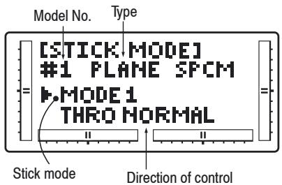
To Trainer menu -UP + Select stick mode/ To Modulation menu DN - direction of control Select stick mode/ SEL - Return to Normal direction of control mode
This is the procedure for changing stick mode:
- Hold DOWN and SELECT pressed in simultaneously while you move the On/Off switch to ON; this takes you to System mode.
- Press UP or DOWN until the screen displays STICK MODE at the top.
- Press (+) or (-) to change the stick mode.
- Pressing Clear resets the stick mode to the factory default (Mode 1).
- Press the DOWN button to move to the MODULATION function.
- Press UP to move on to the TRAINER function.
- You can leave the STICK MODE function by pres
singDOWNandSelectsimultaneously.
Fixed-wing stick mode:
| MODE 1 (Throttle at right stick) | MODE 2 (Throttle at left stick) | ||
| left rudder elev. up | full throttle idle | left rudder elev. up | full throttle elev. up |
| MODE 3 (Throttle at right stick) | MODE 4 (Throttle at left stick) | ||
| left aleron elev. up | full throttle idle | left aleron elev. up | full throttle elev. up |
Helicopter stick mode:
| MODE 1 (Throttle at right stick) | MODE 2 (Throttle at left stick) | ||
| pitch axis | throttle | throttle | pitch axis |
| tail rotor | roll | tail rotor | roll |
| pitch axis | throttle | throttle | pitch axis |
| MODE 3 (Throttle at right stick) | MODE 4 (Throttle at left stick) | ||
| pitch axis | throttle | throttle | pitch axis |
| roll | tail rotor | roll | tail rotor |
| pitch axis | throttle | throttle | pitch axis |
System Mode
Trainer Function
Trainer Function
The mx-12 offers a programmable trainer function with three trainer options:
Normal mode: - In this mode the transmitter acts as a conventional buddy-box system. The transmitter can be used as a slave or as a master: however in this mode, the reversing switches and trims must be adjusted so the slave transmitter matches the master transmitter. In normal mode, when the trainer switch is activated, the student has control of all functions and switches.
Pilot Link: - When Pilot Link mode is used with the master transmitte, it allows the slave transmitter to be adjusted to factory defaults. The slave transmitter can simply be programmed in a model memory not being used and reset to factory defaults, thus preventing the need to synchronize the trims and reversing switches on the slave transmitter. Also when Pilot Link is used, the student only has control of the 4 basic channels (throttle, aileron, elevator, rudder) while the trainer (master) retains control of all other functions like gear, dual rate, programmed mixes, etc. This allows a pilot to have a test flight on a more complex airplane without having to remember complex switch positions.
Pilot Link + Slave: - This mode is used only when the mx-12 is being used as a slave transmitter and the other Master transmitter has a Pilot Link program active. By selecting Pilot Link + Slave the transmitter is automatically in the correct programming mode to work as a slave in conjunction with another Pilot Link equipped transmitter.

Trainer mode selected
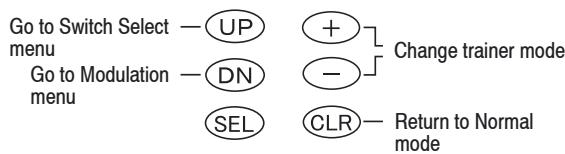
Accessing the Trainer Function
- Move the power switch to the ON position while pressing the Down and Select keys to access the System mode.
- Press either the Up or Down key until TRAINER appears at the too of the LCD.
- Press either the (+) or (-) keys to change the Trainer Type type.
- Pressing the Clear key will return the trainer function to the "normal" setting.
- Press the Down key to access the MODULATION function.
- Press the Up key to access the SWITCH SEL function.
- To exit the TRAINER function, press the Down and Select keys simultaneously.
Note: The slave transmitter must always be in PPM modulation to operate.
Pilot Link + Slave automatically selects PPM modulation when activated.
When using other models of transmitters it will be necessary for the slave transmitter to be in PPM mode for the mx-12.
For Trainer operations you require one of the following accessory leads:
4179.1 Trainer lead for mx-12
For use with Graupner hand-held transmitters with DSC sockets
3290.8 Trainer lead for mx-12
For use with Graupner mc... transmitters with trainer sockets
System Mode
Switch Select
Switch Select
The mx-12 allows the several options to be programmed for the dual rate, gear and flap switches (flight mode switches for heli).
Aileron and Elevator dual rates can be programmed to be individually selected via its own switch (individual) or the aileron, elevator and rudder functions can be combined to operate from one of four switches.
The gear channel can be programmed to operate on one of four switched or rockers or it can be inhibited, helpful for some types of mixing. Plus the flap channel (flight mode channel for heli) can be programmed to operate from switches or levers.
Dual Rate indicator
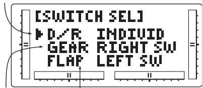
Gear Indicator
Flap indicator (Flight mode indicator for heli)
Go to Wing Type menu for
Airplane (to Swashplate type
menu for Heli)
Go to Trainer menu


Switch selection
Select function


Reset selection to Default
Accessing the Modulation Function (For Airplane) Dual Rates
D/R INDIVID (default)
In this mode the aileron and elevator rates are independently selected using the ELEV D/R and AILE D/R switches.
Note: In this mode the rudder D/R is always in the 0 position and is not selectable. This is the default setting.
COM AILE
In this mode the aileron, elevator and rudder dual rates are combined on the AILE D/R switch.
COM ELEV
In this mode the aileron, elevator and rudder dual rates are combined on the ELEV D/R switch.
COM R-SW
In this mode the aileron, elevator and rudder dual rates are combined on the upper right (flap) switch.
COM L-SW
In this mode the aileron, elevator and rudder dual rates are combined on the upper left (gear) switch.
Gear Channel
LEFT SW (default)
The gear channel operates from the left upper (gear) switch.
AILE D/R
The gear channel operates from the aileron dual rate switch
ROCKER
The gear channel operates from the right rocker switch and offers three positions.
INHIBIT
The gear channel is inhibited and is centered making it useful as a slave channel for mixing.
RIGHT SW
The gear channel operates from the right upper (flap) switch.
Flap Channel
RIGHT SW (default)
The flap channel operates from the right upper (flap) switch.
LEFT SW
The flap channel operates from the left upper (gear) switch.
ELEV D/R
The flap channel operates from the elevator dual rate switch.
FLAP LVR
The flap channel operates from the left flap lever and is proportional.
Accessing the Modulation Function (For Helicopter)
Dual Rates
D/R INDIVID (default)
In this mode the aileron and elevator rates are independently selected using the ELEV D/R and AILE D/R switches.
Note: In this mode the rudder D/R is always in the 0 position and is not selectable. This is the default setting.
COM AILE
In this mode the aileron, elevator and rudder dual rates are combined on the AILE D/R switch.
COM ELEV
In this mode the aileron, elevator and rudder dual rates are combined on the ELEV D/R switch.
COM R-SW
In this mode the aileron, elevator and rudder dual rates are combined on the upper right (flap) switch.
COM L-SW
In this mode the aileron, elevator and rudder dual rates are combined on the upper left (gear) switch.
Gear Channel
LEFT SW (default)
The gear channel operates from the left upper (gear) switch.
AILE D/R
The gear channel operates from the aileron dual rate switch.
System Mode
Wing Type Selection
ELEV D/R
The gear channel operates from the elevator dual rate switch.
INHIBIT
The gear channel is inhibited and is centered making it useful as a slave channel for mixing.
RIGHT SW
The gear channel operates from the right upper (flap) switch.
Flight Mode
LEFT SW (default)
The flight mode operates from the left upper (gear) switch.
AILE D/R
The flight mode operates from the aileron dual rate switch
ELEV D/R
The flight mode operates from the elevator dual rate switch.
RIGHT SW
The flight mode channel operates from the right upper switch.
Wing Type Selection
There are three different wing types to choose from; select the one that will best suit your RC aircraft. Flaperon, Elevon and V-Tail are available selections for Wing Type and will be covered in the following pages.
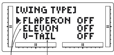
Wing Type V-Tail indicator
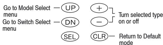
Definition of Wing Types
Normal
This is used with aircraft with one servo operating both ailerons. This mode is the default setting and is active when the Flapneron, Elevon and V-Tail modes are off.
Flaperon
This mode is used when two servos are used to operated the ailerons. Flaperons allow each aileron to be independently adjusted. In addition, they can be programmed to move in the same direction for use as flaps or spoilers.
Elevon
This mode is used for some types of delta wing aircraft where the control surfaces function as both ailerons and elevators.
V-Tail
Used for V-tailed airplanes
Note: Some function will be unavailable when certain functions are active. With Flaperon active, Elevon will be unavailable. With Elevon active, both Flaperon and V-Tail will be unavailable. Finally, with V-Tail active, Elevon will be unavailable.
Flaperon Wing Type Selection
Flaperons allow you to use the existing ailerons as flaps. The ailerons can be raised or lowered in unisonas flaps, yet still remain fully operational as the ailerons of your RC airplane.
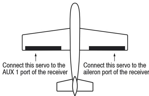
Accessing and Utilizing the Flaperon Wing Type Selection
- While the Down and Select buttons are pressed, move the power switch to the ON position to access the System mode.
- Press either the Up or Down keys until WING TYPE appears in the upper area of the LCD.
- Press either the (+) or (-) key to turnon the Flaperon (FLPR) Wing Type Selection.
Note: For Flaperon, one servo must be used for each aileron control surface.
- Plug the left wing aileron servo into the Auxiliary 1 (AUX1) port of your JR receiver. Connect the right aileron servo into the aileron port (AILE) of your receiver.
- Check to make sure that the wing servos move in the proper direction. For a right turn, the right aileron should raise while the left aileron lowers simultaneously. For a left turn, the opposite is true; the left aileron should rise while the right aileron drops. If your servos are not moving in the direction just described, use the Servo Reversing function to reverse the travel direction of the servo(s) that are moving improperly. Refer to the Servo Reversing section for information on how to reverse the travel
System Mode
direction.
Note: Each servo's travel direction is adjusted individually through the Servo Reversing function.
Once the servos achieve their proper travel direction, adjust their travel amount, dual rates, sub-trim and aileron differential.
Note: The applicable channel's left or right travel adjustment may be made individually by accessing the Travel Adjust function. Refer to the Travel Adjust section of this manual for more information. The fine adjustments of your aileron controls should be made in the Dual-Rate function. Refer to the Dual-Rate section for information on how to do so. You can also adjust the neutral point of your aileron servos individually through the use of the Sub-Trim function. Refer to the Sub-Trim section of this manual for more information.
- The flap lever located on the left face of the transmitter controls the aileron movements as flaps. To turn off flaps go to the Flap System function on page 39 and reduce the flap value to 0% .
Note: Differential is offered for the Flaperon function of your mx-12. For more information, please refer to the Differential section of this manual.
- Press the Down key to access the SWITCH SEL function.
- Press the Up key to access the MODEL SEL function.
- Exit the WING TYPE function by pressing the Down and Select keys simultaneously.
Elevon Type Selection
Elevon Wing Mixing is available as an option with your mx-12. This style of aircraft also employs two wing
servos. However, there is not an elevator present. Instead, an elevator stick input causes the two wing servos to function in conjunction with one another to change the pitch movement of the aircraft. Also, when an aileron control is given the two wing servos move in opposition to one another to function as ailerons.
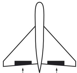
Connect left servo to the aileron port of the receiver
Connect right servo to the elevator port of the receiver
Accessing and Utilizing the Elevon Type Selection
- While the Down and Select keys are pressed, move the power switch to the ON position to access the System mode.
- Press either the Up or Down key until WING TYPE appears on the LCD.
- Press the Select key to select the Elevon functions.
- Press either the (+) or (-) key to turn on the Elevon Wing Type function.
Note: The Elevon function requires one servo for each elevator, i.e. a separate servo for each wing half.
- Plug the left elevon servo to the aileron (AILE) of your GRAUPNER receiver. Connect the right elevon servo into the elevator (ELEV) port of your receiver.
- Check to make sure the servos move in the proper direction. When an input is given from the elevator stick, they should move in unison to achieve the proper up/down elevator command. If your servos do not move as described above, use the Servo Rever-
sing function to reverse the travel direction.
Note: Each servo's direction is adjusted individually through the Servo Reversing function. For more information, refer to the Servo Reversing section in this manual.
7. Once the servos direction has been set, adjust their travel direction, travel volume, dual-rates, sub-trim and aileron differential.
Note: The applicable channel's left or right, up or down travel adjustments can be made individually. Refer to the Travel Adjust section in this manual for more information.
8. Relative to the note above, each servo's travel volume is automatically reduced to 75% of the operating range. This is to ensure that the servo does not operate beyond its capabilities. Failure to observe extreme caution when adjusting the value for the elevon servos may result in damage to the servos by over traveling.
Note: Fine adjustments of the elevons should be made in the Dual-Rate function. For more information, refer to the Dual-Rate section in this manual. You can also adjust the neutral point of your levon servos individually using the Sub-Trim function as described in the Sub-Trim section of this manual. Differential is offered for the levon function of your mx-12. For more information, refer to the Differential Aileron Mixing section of this manual.
9. Press the Down key to access the SWITCH SEL function.
10. Press the Up key to access the MODEL SEL function.
11. To exit the WING TYPE function, press the Down and Select keys simultaneously.
System Mode
V-Tail Type Selection
V-tail mixing is available as an option with your mx-12. V-tail equipped aircraft require two servos.
Connect left servo to the aileron port of the receiver
Connect right servo to the elevator port of the receiver
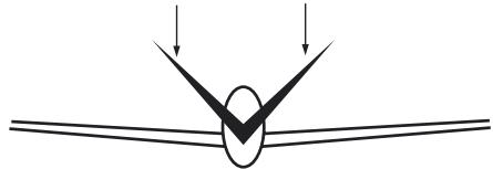
Accessing and Utilizing the V-Tail Type Selection
- While the Down and Select keys are pressed, move the power switch to the ON position to access the System mode.
- Press either the Up or Down key until WING TYPE appears on the LCD.
- Press the Select key to select the V-Tail function.
- Press either the (+) or (-) key to turn on the V-Tail Wing Type function.
- Connect the servo that controls the left tail control surface to the elevator (#3) channel in the receiver and the servo that controls the right control surface to the rudder (#4) channel in the receiver.
Note: Individual functions like reversing, travel adjust, dual rates, sub trims etc. are available for each servo independently.
- Check to make sure the servos move in the proper direction. When an input is given from the elevator stick, they should move in unison to achieve the proper up/down elevator command. If your servos do not move in the correct direction, use the Servo Reversing function to reverse the travel direction.
Note: Each servo's direction is adjusted individually through the Servo Reversing function. For more information, refer to the Servo Reversing section
in this manual.
- Once the servos direction has been set, adjust their travel direction, travel adjust, dual rates, sub-trim.
Note: The applicable channel's left or right, up or down travel adjustments can be made individually. Refer to the Travel Adjust section in this manual for more information. - Relative to the note above, each servo's travel volume is automatically reduced to 50% of the operating range. This is to ensure that the servo does not operate beyond its capabilities. Failure to observe extreme caution when adjusting the value for the levon servos may result in damage to the servos by over traveling.
Note: Fine adjustments of the V-Tail should be made in the Dual-Rate function. For more information, refer to the Dual-Rate section in this manual. You can also adjust the neutral point of your V-Tail servos individually using the Sub-Trim function as described in the Sub-Trim section of this manual. - Press the Down key to access the SWITCH SEL function.
- Press the Up key to access the MODEL SEL function.
- To exit the WING TYPE function, press the Down and Select keys simultaneously.
System Mode
Swashplate Type Selection
Swashplate Type Selection
The Swashplate Mixing function enables the mx-12 system to operate many different types of swashplate control systems, including 3 versions of CCPM.
Initial Setting
1 Servo (Normal)
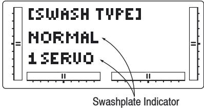
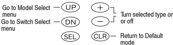
The Swashplate options are:
1 Servo: Non-CCPM, standard mixing type helicopter
2 Servo/180°CCPM
3 Servo/120° CCPM (GRAUPNER style, most popular)
4 Servo/90°CCPM
Definition of Swashplate Types
- While pressing the Down and Select keys, switch the transmitter to the ON position to enter the system mode.
- Press either the Up or Down key until SWASH TYPE is displayed in the upper center portion of the LCD.
- Press the (+) or (-) keys to change the Swashplate type.
- Pressing the Clear key will reset the Swashplate Type to the Normal position. 7. To access the AUX2
Switch function, press the Down key.
- Press the Up key to access the MODEL SELECT function.
- Press the Down key to access the SWITCH SELECT function.
- Exit the SWASH TYPE function by pressing the Down and Select keys simultaneously.
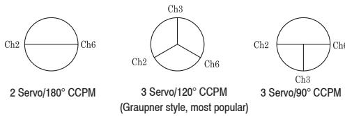
CCPM Servo Variations
Approved operating frequencies, available crystals, frequency pennants
Thi[]
situation in your own country. It is prohibited to operate a radio control system on any frequency and channel other than those listed.
| Frequency band | Approval | Channel No. | Transmitter frequency, MHz | FMssrs crystals | Precision crystals | DS crystals Dual-conversion crystals, Order No. | Approval by country (please check) | ||||||||||||||
| Transmitter, Order No. | Receiver, Order No. | Transmitter, Order No. | Receiver, Order No. | D | B | A | DK | FI | I | L | N | NL | S | CH | |||||||
| 35MHz-Band Band A | FE(for model aircraft only) | 61 | 35,010 | 3864.61 | 3865.61 | 3264.61 | 3265.61 | 3270.61 | |||||||||||||
| 62 | 35,020 | .62 | .62 | .62 | .62 | .62 | |||||||||||||||
| 63 | 35,030 | .63 | .63 | .63 | .63 | .63 | |||||||||||||||
| 64 | 35,040 | .64 | .64 | .64 | .64 | .64 | |||||||||||||||
| 65 | 35,050 | .65 | .65 | .65 | .65 | .65 | |||||||||||||||
| 66 | 35,060 | .66 | .66 | .66 | .66 | .66 | |||||||||||||||
| 67 | 35,070 | .67 | .67 | .67 | .67 | .67 | |||||||||||||||
| 68 | 35,080 | .68 | .68 | .68 | .68 | .68 | |||||||||||||||
| 69 | 35,090 | .69 | .69 | .69 | .69 | .69 | |||||||||||||||
| 70 | 35,100 | .70 | .70 | .70 | .70 | .70 | |||||||||||||||
| 71 | 35,110 | .71 | .71 | .71 | .71 | .71 | |||||||||||||||
| 72 | 35,120 | .72 | .72 | .72 | .72 | .72 | |||||||||||||||
| 73 | 35,130 | .73 | .73 | .73 | .73 | .73 | |||||||||||||||
| 74 | 35,140 | .74 | .74 | .74 | .74 | .74 | |||||||||||||||
| 75 | 35,150 | .75 | .75 | .75 | .75 | .75 | |||||||||||||||
| 76 | 35,160 | .76 | .76 | .76 | .76 | .76 | |||||||||||||||
| 77 | 35,170 | .77 | .77 | .77 | .77 | .77 | |||||||||||||||
| 78 | 35,180 | .78 | .78 | .78 | .78 | .78 | |||||||||||||||
| 79 | 35,190 | .79 | .79 | .79 | .79 | .79 | |||||||||||||||
| 80 | 35,200 | .80 | .80 | .80 | .80 | .80 | |||||||||||||||
| Band B Only for equipment approved for use on Band B.Existing units can be re-tuned by our Service Department | (for model aircraft only) | 182 | 35,820 | .182 | .182 | .182 | .182 | .182 | |||||||||||||
| 183 | 35,830 | .183 | .183 | .183 | .183 | .183 | |||||||||||||||
| 184 | 35,840 | .184 | .184 | .184 | .184 | .184 | |||||||||||||||
| 185 | 35,850 | .185 | .185 | .185 | .185 | .185 | |||||||||||||||
| 186 | 35,860 | .186 | .186 | .186 | .186 | .186 | |||||||||||||||
| 197 | 35,870 | .187 | .187 | .187 | .187 | .187 | |||||||||||||||
| 188 | 35,880 | .188 | .188 | .188 | .188 | .188 | |||||||||||||||
| 189 | 35,890 | .189 | .189 | .189 | .189 | .189 | |||||||||||||||
| 190 | 35,900 | .190 | .190 | .190 | .190 | .190 | |||||||||||||||
| 191 | 35,910 | .191 | .191 | .191 | .191 | .191 | |||||||||||||||
| 40MHz-Band | MF | 50 | 40,665 | 4064.50 | 4065.50 | 3240.50 | |||||||||||||||
| 51 | 40,675 | .51 | .51 | .51 | |||||||||||||||||
| 52 | 40,685 | .52 | .52 | .52 | |||||||||||||||||
| 53 | 40,695 | .53 | .53 | .53 | |||||||||||||||||
| (for model boats and cars only) | 54 | 40,715 | .54 | .54 | .54 | ||||||||||||||||
| 55 | 40,725 | .55 | .55 | .55 | |||||||||||||||||
| 56 | 40,735 | .56 | .56 | .56 | |||||||||||||||||
| 57 | 40,765 | .57 | .57 | .57 | |||||||||||||||||
| 58 | 40,775 | .58 | .58 | .58 | |||||||||||||||||
| 59 | 40,785 | .59 | .59 | .59 | |||||||||||||||||
| 81 | 40,815 | .81 | .81 | .81 | |||||||||||||||||
| 82 | 40,825 | .82 | .82 | .82 | |||||||||||||||||
| 83 | 40,835 | .83 | .83 | .83 | |||||||||||||||||
| 84 | 40,865 | .84 | .84 | .84 | |||||||||||||||||
| 85 | 40,875 | .85 | .85 | .85 | |||||||||||||||||
| 86 | 40,885 | .86 | .86 | .86 | |||||||||||||||||
| 87 | 40,915 | .87 | .87 | .87 | |||||||||||||||||
| 88 | 40,925 | .88 | .88 | .88 | |||||||||||||||||
| 89 | 40,935 | .89 | .89 | .89 | |||||||||||||||||
| 90 | 40,965 | .90 | .90 | .90 | |||||||||||||||||
| 91 | 40,975 | .91 | .91 | .91 | |||||||||||||||||
| 92 | 40,985 | .92 | .92 | .92 | |||||||||||||||||
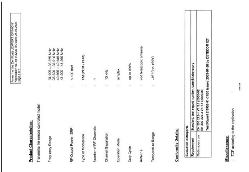
EU conformity declaration
CETECOM ICT Services GmbH
CERTIFICATE OF CONFORMITY
EB14320S-CC Number of annexes: —
(transmitter for remote cont)
Grapier GmbH & Co.KG Hamburgerstrasse 31-46
Act (FTEG) and Directive 1999/5/EG (R&TTE)
Newark, Nottinghamshire
NG24 2EG
( +44) 16 36 61 05 39
RC Service Z. Hnizdil
Letecka 666/22
CZ-16100 Praha 6 - Ruzyne
(+42)233313095
Belgie/Nederland
Jan van Mouwerik
Slot de Houvelaan 30
NL 3155 Maasland VT
(+)105913594
Graupner GmbH & Co. KG, Henriettenstraße 94-96. 73230 Kirchheim/Teck, Germany guarantees this product for a period of 24 months from date of purchase. The guarantee applies only to such material or operational defects witch are present at the time of purchase of the product. Damage due to wear, overloading, incompetent handling or the use of incorrect accessories is not covered by the guarantee. The user's legal rights and claims under guarantee are not affected by this guarantee. Please check the product carefully for defects before you are make a claim or send the item to us, since we are obliged to make a charge for our cost if the product is found to be free of faults.
Date of purchase/delivery:
Date de remise:
Name des Kaufers:
Owner's name:
Nom de I'achateur:
StraBe, Wohnort:
Complete adress:
Domicie et rue:
Stamp and signature of dealer:
R E M O T E C O N T R O L
GRAUPNER GMBH & CO. KG POSTFACH 1242 D-73220 KIRCHHEIM/TECK GERMANY http://www.graupner.de
Availability and changes to specifications reserved.
Supplied only through approved specialist dealers.
We will gladly supply addresses of suppliers. We
accept no liability for printing errors.
Printed in Germany 05/05
We have checked the information in these instructions with great care and believe it to be correct. However, we accept no liability of any kind for errors, omissions and printing errors. GRAUPNER reserves the right to modify the software and hardware features described in this manual at any time and without prior notification.

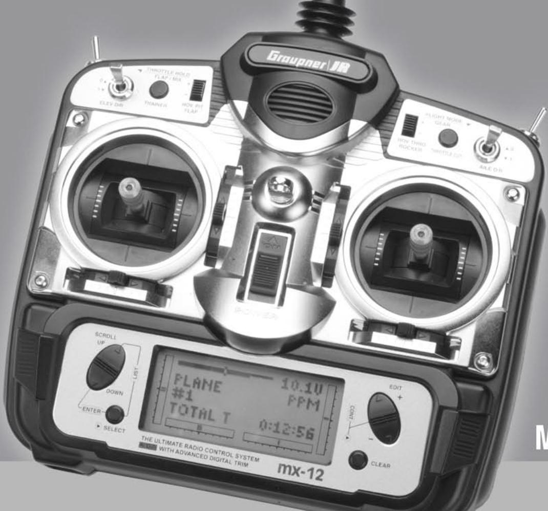
mx-12
ROTARY-SELECT
Manuel de Programmation
Computer System mx-12
Les sets contiennent:
Direct Servo Control (DSC)
Instructions d-installation
Mode Fonctions (List)
4: Direction
5: Train rentrant
6: Voles
ELEV D/R: ELEV D/R Position 1→EON
Gaskurve (Throttle Curve)
Courbe de pitch (Pitch Curve)
In the essential requirements of 3 and the other relevant provisions of the FTEG (Article 3 of the
(Active), when used for its intended purpose
Measures for the efficient use of the radio frequency spectrum 3(2) (Article 3 (2))
S82
10 : 1 = 120 °
04M2005
04. Mai 2005 Hans Graupner, Gene Hans Graupner, Maneg
G GmbH & Co. KG Henriettenastraße 94-96 D-73230 Kirch H7230, Germany Fax: 07921723-188 E-mail:
Servicestellen / Service / Service après-venture
Graupner-Zentralservice
Newark, Nottinghamshire
NG24 2EG
( +44) 16 36 61 05 39
RC Service Z. Hnizdil
Letecka 666/22
CZ-16100 Praha 6 - Ruzyne
(+42)233313095
Belgie/Nederland
Jan van Mouwerik
Slot de Houvelaan 30
NL 3155 Maasland VT
(+)105913594
Graupner GmbH & Co. KG, Henriettenstraße 94-96. 73230 Kirchheim/Teck, Germany guarantees this product for a period of 24 months from date of purchase. The guarantee applies only to such material or operational defects which are present at the time of purchase of the product. Damage due to wear, overloading, incompetent handling or the use of incorrect accessories is not covered by the guarantee. The user's legal rights and claims under guarantee are not affected by this guarantee. Please check the product carefully for defects before you are make a claim or send the item to us, since we are obliged to make a charge for our cost if the product is found to be free of faults.
Date of purchase/delivery:
Date de remise:
Name des Kaufers:
Owner's name:
Nom de I'achateur:
StraBe, Wohnort:
Complete adress:
Domicie et rue:
Stamp and signature of dealer:
R E M O T E C O N T R O L
GRAUPNER GMBH & CO. KG POSTFACH 1242 D-73220 KIRCHHEIM/TECK GERMANY http://www.graupner.de





- COMPUTER SYSTEM MX-12
- DIRECT SERVO CONTROL (DSC)
- GASKURVEN (THROTTLE CURVE)
- PITCHKURVEN (PITCH CURVE)
- SYSTEM-MODUS
- BELGIE/NEDERLAND
- R E M O T E C O N T R O L
- CONNECTIONS AND INSTALLATIONS
- PROGRAM
- FUNCTION MODE AIRPLANE
- FUNCTION MODE HELICOPTER
- SYSTEM MODE
- APPENDIX
- ENVIRONMENTAL PROTECTION NOTES
- SAFETY NOTES
- PLEASE READ CAREFULLY
- APPLICATION
- INSTALLING THE RECEIVING SYSTEM AND DEPLOYING THE RECEIVER AERIAL
- INSTALLING THE SERVOS
- INSTALLING CONTROL LINKAGES
- ALWAYS EXTEND THE TRANSMITTER AERIAL FULLY BEFORE OPERATING YOUR MODEL
- PRE-FLIGHT CHECKING
- ALWAYS SWITCH ON THE TRANSMITTER FIRST, AND ONLY THEN THE RECEIVER
- ALWAYS SWITCH OFF THE RECEIVER FIRST, AND ONLY THEN THE TRANSMITTER
- RANGE CHECKING
- CHECKING THE TRANSMITTER AND RECEIVER BATTERIES
- CAPACITY AND OPERATING TIMES
- SUPPRESSING ELECTRIC MOTORS
- SERVO SUPPRESSOR FILTER FOR EXTENSION LEADS
- USING ELECTRONIC SPEED CONTROLLERS
- ELECTRICAL IGNITION SYSTEMS
- CAUTION
- STATIC CHARGES
- STATIC CHARGES THROUGH THE TRANSMITTER AERIAL CAN BE LIFE-THREATENING
- CARE AND MAINTENANCE
- LIABILITY EXCLUSION / COMPENSATION
- SET CONTENTS
- ACCESSOIRES
- SPARE PARTS
- CHARGING THE TRANSMITTER BATTERY
- POLARITY OF THE MX-12 CHARGE SOCKET
- CHARGE CURRENT
- NOTES ON RECHARGING TRANSMITTER BATTERIES USING AN AUTOMATIC CHARGER
- STANDARD CHARGERS
- AUTOMATIC CHARGERS WITH SPECIAL NIMH CHARGE PROGRAMS
- TRANSMITTER DESCRIPTION
- TRANSMITTER CALLOUTS
- CONTROL STICK LENGTH ADJUSTMENT
- NECK STRAP ATTACHMENT
- CONTROL STICK TENSION ADJUSTMENT
- THROTTLE STICK
- FREQUENCY NOTES
- BE CERTAIN TO OBSERVE THE FOLLOWING GUIDELINES
- FOR PROPER DSC HOOK-UP AND OPERATION
- WHY YOU SHOULD USE THE DSC FUNCTION
- INSTALLATION REQUIREMENTS
- WARNING
- KEY INPUT AND DISPLAY; ALARM AND ERROR DISPLAY
- BATTERY ALARM AND DISPLAY
- BACKUP ERROR DISPLAY
- INPUT MODE AND FUNCTION
- NORMAL MODE
- SCREEN CONTRAST ADJUSTMENT
- ADVANCED DIGITAL TRIM (A.D.T.)
- MODEL OPERATING TIME
- FUNCTION MODE FLOWCHART
- ACCESSING THE MODE FUNCTION
- AIRPLANE
- HELICOPTER
- SYSTEM MODE FLOWCHART
- ACCESSING THE SYSTEM MODE
- LIST MODE
- DUAL RATES AND EXPONENTIAL; SERVO REVERSING
- ACCESSING THE DUAL-RATE AND EXPONENTIAL FUNCTION
- ACCESSING THE TRAVEL ADJUST FUNCTION
- SUB TRIM; TRAVEL ADJUST
- SUB TRIM
- ACCESSING THE SUB TRIM FUNCTION
- TRAVEL ADJUST
- ELEVATOR TO FLAP MIXING; AILERON TO RUDDER MIXING
- ELEVATOR TO FLAP MIXING
- ACCESSING THE ELEVATOR TO FLAP FUNCTION
- AILERON TO RUDDER MIXING
- ACCESSING THE AILERON TO RUDDER MIXING FUNCTION
- THROTTLE CUT SWITCH
- ACCESSING THE THROTTLE CUT FUNCTION
- FLAP SYSTEM
- ACCESSING THE FLAP SYSTEM FUNCTION
- DIFFERENTIAL AILERON MIXING; PROGRAMMABLE MIXING (1~4)
- DIFFERENTIAL AILERON MIXING
- DIFFERENTIAL VALUE
- PROGRAMMABLE MIXING (1~4)
- ACCESSING THE PROGRAMMABLE MIXING FUNCTION
- SELECTING THE MASTER AND SLAVE MIXING CHANNELS
- SETTING THE MIXING VALUES
- SETTING THE MIXING SWITCH ACTIVATION
- MIXING OPERATION AND SWITCHES
- SETTING THE MIXING CHANNEL OFFSET
- FAIL SAFE
- ACCESSING THE FAIL SAFE FUNCTION
- SERVO TRAVEL SCREEN
- ACCESSING THE SERVO TRAVEL SCREEN
- DUAL RATES AND EXPONENTIAL
- ACCESSING THE DUAL RATE AND EXPONENTIAL FUNCTION
- SERVO REVERSING
- ACCESSING THE SERVO REVERSE FUNCTION
- CCPM SWASHPLATE MIXING
- ACCESSING THE SWASHPLATE TYPE
- CCPM SERVO VARIATIONS
- THROTTLE CUT SWITCH; THROTTLE HOLD
- THROTTLE HOLD
- ACCESSING THE THROTTLE HOLD FUNCTION
- THROTTLE CURVES
- ACCESSING THE THROTTLE CURVE FUNCTION
- THROTTLE TIME SETTINGS
- PITCH CURVES
- HOVERING THROTTLE LEVER SETTINGS
- ACCESSING THE PITCH CURVE FUNCTION
- HOVERING PITCH LEVER
- REVOLUTION MIXING (NON-HEADING LOCK GYROS ONLY)
- ACCESSING THE REVOLUTION MIXING FUNCTION
- SETTING UP REVOLUTION MIXING (NON-HEADING LOCK, GYROS ONLY)
- PROGRAMMABLE MIXING (1~2)
- SELECTION THE MASTER AND SLAVE MIXING CHANNELS
- MODEL SELECTION; MODEL NAME ENTRY
- MODEL SELECTION
- ACCESSING THE MODEL SELECT FUNCTION
- MODEL NAME ENTRY
- SELECTABLE CHARACTER
- MODEL TYPE SELECTION; MODEL COPY FUNCTION
- MODEL TYPE SELECTION
- ACCESSING THE TYPE SELECTION FUNCTION
- MODEL COPY FUNCTION
- ACCESSING THE MODEL COPY FUNCTION
- MODULATION SELECTION, STICK MODE
- MODULATION SELECTION
- ACCESSING THE MODULATION FUNCTION
- STICK MODE
- THIS IS THE PROCEDURE FOR CHANGING STICK MODE
- FIXED-WING STICK MODE
- HELICOPTER STICK MODE
- TRAINER FUNCTION
- ACCESSING THE TRAINER FUNCTION
- FOR TRAINER OPERATIONS YOU REQUIRE ONE OF THE FOLLOWING ACCESSORY LEADS
- SWITCH SELECT
- ACCESSING THE MODULATION FUNCTION (FOR AIRPLANE) DUAL RATES
- D/R INDIVID (DEFAULT)
- COM AILE
- COM ELEV
- COM R-SW
- COM L-SW
- GEAR CHANNEL
- LEFT SW (DEFAULT)
- AILE D/R
- ROCKER
- INHIBIT
- RIGHT SW
- FLAP CHANNEL
- RIGHT SW (DEFAULT)
- LEFT SW
- ELEV D/R
- FLAP LVR
- ACCESSING THE MODULATION FUNCTION (FOR HELICOPTER)
- DUAL RATES
- WING TYPE SELECTION
- FLIGHT MODE
- DEFINITION OF WING TYPES
- NORMAL
- FLAPERON
- ELEVON
- V-TAIL
- FLAPERON WING TYPE SELECTION
- ACCESSING AND UTILIZING THE FLAPERON WING TYPE SELECTION
- ELEVON TYPE SELECTION
- ACCESSING AND UTILIZING THE ELEVON TYPE SELECTION
- V-TAIL TYPE SELECTION
- ACCESSING AND UTILIZING THE V-TAIL TYPE SELECTION
- SWASHPLATE TYPE SELECTION
- THE SWASHPLATE OPTIONS ARE
- DEFINITION OF SWASHPLATE TYPES
- APPROVED OPERATING FREQUENCIES, AVAILABLE CRYSTALS, FREQUENCY PENNANTS
- EU CONFORMITY DECLARATION
- MX-12
- ROTARY-SELECT
- LES SETS CONTIENNENT
- INSTRUCTIONS D-INSTALLATION
- MODE FONCTIONS (LIST)
- GASKURVE (THROTTLE CURVE)
- COURBE DE PITCH (PITCH CURVE)
- SERVICESTELLEN / SERVICE / SERVICE APRÈS-VENTURE
- GRAUPNER-ZENTRALSERVICE
Brand : GRAUPNER
Model : MX-12
Category : Radio transmitters for modeling